

Page 1
OPERATOR’S MANUAL WLM2203A-X
INCLUDING: SPECIFICATIONS, SERVICE KITS, GENERAL INFORMATION, PARTS, TROUBLESHOOTING
INCLUDE MANUAL: S-633 GENERAL INFORMATION (PN 97999-625)
2” AIR MOTOR
WLM2203A-XX
3:1 RATIO
0 - 375 P.S.I. RANGE
TWO-BALL PUMP SERIES
READ THIS MANUAL CAREFULLY BEFORE INSTALLING,
OPERATING OR SERVICING THIS EQUIPMENT.
It is the responsibility of the employer to place this information in the hands of the operator. Keep for future reference.
RELEASED: 5-3-99
REVISED: 8-1-11
(REV. G)
SERVICE KITS
• Use only genuine AROR replacement parts to assure compatible
pressure rating and longest service life.
• 637224 Pump Rebuild Kit. Includes the necessary soft parts for
normal service of the entire pump.
SPECIFICATIONS
Model Series (Refer to option chart) WLM2203A-XX.......
Type Air Operated, Two Ball,.........................
Double Acting Oil Pump
Ratio 3:1.........................
Air Motor Diameter 2” (5.08 cm)..............
Stroke 3” (7.62 cm)......................
Air Inlet (female)
models WLM2203A-X1
models WLM2203A-X2
Material Inlet (female)
models WLM2203A-X1
models WLM2203A-X2
Material Outlet (female)
models WLM2203A-X1
models WLM2203A-X2
Pump Construction Carbon Steel............
Dimensional Data see “Pump Data”...............
Weight see chart........................
1/4 - 18 N.P.T.F. - 1......
Rc 1/4 (1/4 - 19 BSP Taper)......
3/4 - 14 N.P.T.......
Rp 3/4 (3/4 - 14 BSP Parallel)......
1/2 - 14 N.P.T.......
Rp 1/2 (1/2 - 14 BSP Parallel)......
‘‘A”
18-1/32”
(458.0 mm)
(33.4 mm)
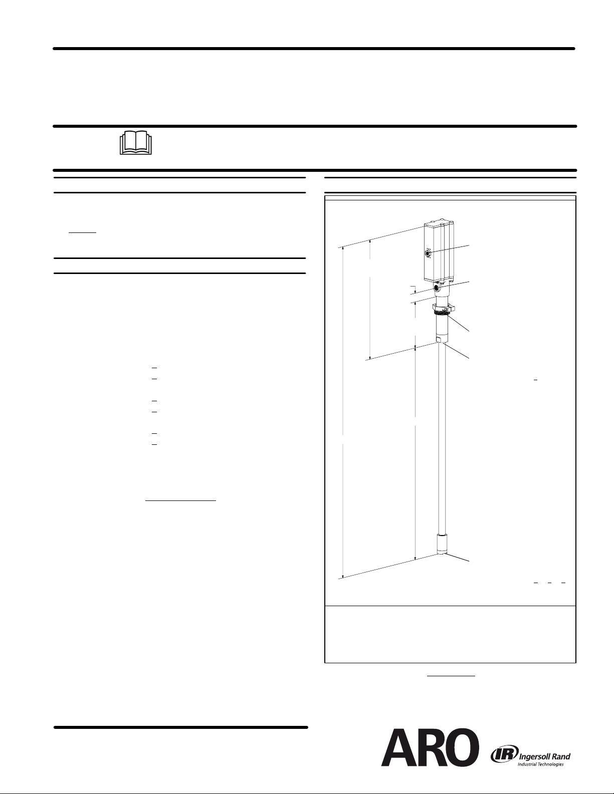
PUMP DATA
MODEL WLM2203A-XX
1-5/16”
6-29/32”
(175 mm)
‘‘B”
Air Inlet (female)
See “Specifications”
Material Outlet (female)
See “Specifications”
NOTE: Pump is assembled
with material outlet located
180_ from the air inlet.
2” N.P.T. Bung Adapter
Material Inlet (female)
See “Specifications”
Models WLM2203A-1
X
Figure 1
PERFORMANCE
Air Inlet Pressure Range 0 - 125 p.s.i. (0 - 8.6 bar)..........
Fluid Pressure Range 0 - 375 p.s.i. (0 - 25.9 bar)............
Maximum Rec’d Cycles / Minute 125....
Displacement In
Volume / Cycle 3.46 oz. (102.28 ml)..................
Cycles Per Gallon (Liter) 37 (9.8)..........
Maximum Working Flow Rate 6 g.p.m. (23 l.p.m.)......
Maximum Flow Rate 9 g.p.m. (34 l.p.m.).............
Noise Level @ 100 p.s.i. - 124 c.p.m. 80 db(A)*..
Accessories Available 61113 Wall Mount Bracket............
* The pump soundpressure levelhas beenupdated toan Equivalent Continuous Sound
Level (L
Aeq
microphone locations.
INGERSOLL RAND COMPANY
209 NORTH MAIN STREET -- BRYAN, OHIO 43506
(800) 495--0276 D FAX FAX(800) 892 --6276
www.ingersollrandproducts.com
3
Per Cycle 6.2........
66073-1 Air Line Connection Kit
) to meetthe intent ofANSI S1. 13-1971,CAGI-PNEUROP S5.1 using four
PATE NT ED
E2011
Material Inlet (female)
See “Specifications”
Models WLM2203A-3
NOTE: Dimensions are shown in inches and (mm), supplied for reference only and are typically
rounded up to the nearest 1/16 inch.
MODEL “A” (mm) “B” (mm) WEIGHT (kg)
WLM2203A-1X N / A N / A 11 (4.99)
WLM2203A-3X 40-1/16” (1017.3) 22-1/32” (559.3) 13.5 (6.12)
WLM2203A-4X 49-13/16” (1265.0) 31-25/32” (806.9) 14.4 (6.53)
WLM2203A-5X 57-7/16” (1458.6) 39-13/32” (1000.6) 15 (6.80)
X, -4X, -5X
IMPORTANT
This is one of two documents which support the pump. Replacement copies of these forms are available upon request.
= WLM2203A-XX MODEL OPERATOR’S MANUAL
- S-633 GENERAL INFORMA TION LUBRICATION PISTON PUMPS
Page 2
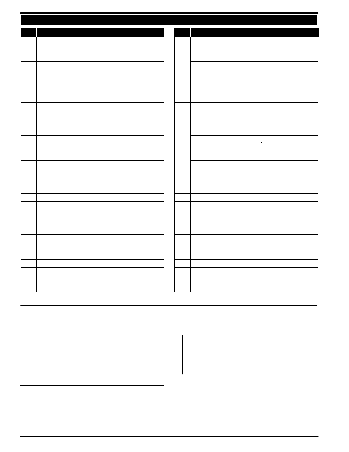
PARTS LIST / WLM2203A-XX
Item Description (size in inches) Qty Part No. Item Description (size in inches) Qty Part No.
1 Bolt (4) 94333
2 Upper Cap (1) 95035
n 3 Track Gasket (2) 94311
4 Sleeve (2) 94316
n 5 “O” Ring (1/16” x 11/16” o.d.) (4) Y325-15
n 6 “O” Ring (1/8” x 3/4” o.d.) (4) Y325-206
7 Spool (2) 94310
n 8 “U” Cup (1/8” x 3/4” o.d.) (2) Y240-7
n 9 “O” Ring (.106” x .587” o.d.) (2) 15066-PM
10 Muffler (1) 95037
11 Cylinder (1) 94249
12 Retaining Ring (1) 94406
n 13 “U” Cup (3/16” x 2” o.d.) (2) Y240-23
14 Piston (1) 94780
15 Lower Cap (1) 95038
n 16 “O” Ring (1/8” x 1-3/8” o.d.) (1) Y325-216
17 Bushing (1) 94332
n 18 Packing (1/4” x 1-5/8” o.d.) (1) 94337
n 19 “O” Ring (3/32” x 1” o.d.) (1) Y325-117
20 Piston Rod (1) 94779
21 Groove Pin (3/16” o.d. x 1-1/8” long) (1) 94338
22 Spring (1) 94705
23 Ball (.7500” dia.) (1) Y16-224
24 Inner Check (1) 94279
n 25 “O” Ring (3/16” x 1-7/16” o.d.) (1) Y325-319
26 Base (models WLM2203A-X1) (1) 94309
(models WLM2203A-X2) (1) 94309-1
27 Nut (4) 93828
n 28 Copper Gasket (1) 96031
29 Tube (1) 94314-1
n 30 “O” Ring (3/32” x 1-9/16” o.d.) (1) Y325-126
31 Ball (1.000” dia.) (1) 90532-6
32 Ball Stop Pin (.187” dia. x 1.430” long) (1) 94339
33 Foot Valve (models WLM2203A-X1) (1) 94315
(models WLM2203A-X2) (1) 94315-1
n 34 “O” Ring (1/16” x 7/16” o.d.) (1) Y325-11
36 Adapter (models WLM2203A-X1) (1) 94447
(models WLM2203A-X2) (1) 94447-1
37 Foam Liner (2) 95039
38 Ground Screw (#10 - 32 x 1/4”) (1) 93005
39 Bung Ass’y (includes items 40 and 49) (1) 67145-3-B
40 Thumb Screw (1/4” - 20 x 1-1/2”) (1) Y197-158-C
41 Pipe Extension - (models WLM2203A-31) (1) 94523-3
3/4 - 14 N.P.T. x 30-1/8” - (models WLM2203A-41) (1) 94523-4
3/4 - 14 N.P.T. x 37-3/4” - (models WLM2203A-51) (1) 94523-5
Rp 3/4 (3/4 - 14 BSP taper x 20-3/8”) - (WLM2203A-32) (1) 94537-3
Rp 3/4 (3/4 - 14 BSP taper x 30-1/8”) - (WLM2203A-42) (1) 94537-4
Rp 3/4 (3/4 - 14 BSP taper x 37-3/4”) - (WLM2203A-52) (1) 94537-5
42 Valve Housing (WLM2203A-X1) (1) 94535
(WLM2203A-X2) (1) 94535-1
43 Ball Guide (1) 77904
44 Ball (1.0000” dia.) (1) Y16-232
n 45 “O” Ring (3/32” x 1-7/16” o.d.) (1) Y325-124
46 Ball Seat (models WLM2203A-X1) (1) 94534
(models WLM2203A-X2) (1) 94534-1
47 Valve Ass’y (includes items 42 thru 46)
(models WLM2203A-31, -41, -51) (1) 67085
(models WLM2203A-32, -42, -52) (1) 67085-1
48 Washer (1) 94515
49 Nut (1/4” - 20) (1) Y12-4-C
n Gadus S2 U1000 Grease Packet (1) 94833
n Parts in Repair Kit 637224
GENERAL DESCRIPTION
Model WLM2203A-XX series two-ball double acting pumps are intended to be used primarily for oil transfer and delivery systems. It isbest
to use this pump with low -- medium viscosity fluids. It uses carbon steel
and other materials which make it compatible with most petroleum
based lubrication products. The two-ball design provides better priming
of the lower foot valve. Double acting pumps will deliver material on both
the up and down stroke.
NOTE: If this pump was purchased separately (not part of a system),
consult your sales representative for compatible dispensing accessories which will best match the application. All accessories must be able
to withstand the maximum pressure developed by the pump.
OPERATING AND SAFETY PRECAUTIONS
READ THE GENERAL INFORMATION MANUAL INCLUDED FOR
ADDITIONAL OPERATING AND SAFETY PRECAUTIONS AND
OTHER IMPORTANT INFORMATION.
STATIC SPARK. Can cause explosion resulting in severe injury or
death. Ground the pump and pumping system.
EXCESSIVE INLET PRESSURE. Can cause explosion resulting in
severe injury or death. Do not exceed maximum operating
pressure of 25.5 bar (370 p.s.i.) at 8.5 bar (123 p.s.i.) inlet air
pressure. Do not run pump without using a regulator to limit air
supply pressure to the pump.
INLET PRESSURE TO PUMP MOTOR
PUMP RATIO X
Pump ratio is an expression of the relationship between the pump motor area and
the lower pump end area. EXAMPLE: When 125 p.s.i. (8.6 bar) inlet pressure is
supplied to the motor of a 3:1 ratio pump it will develop a maximum of 375 p.s.i.
(25.9 bar) fluid pressure (at no flow) -- as the fluid control is opened, the flow rate
will increase as the motor cycle rate increases to keep up with the demand.
MAXIMUM PUMP
=
FLUID PRESSURE
EXCESSIVE MATERIAL PRESSURE. Can cause equipment failure
resulting in severe injury or property damage. Do not exceed the
maximum material pressure of any component in the system.
NOTICE: Thermal expansion can occur when the fluid in the material lines is exposed to elevated temperatures. Example: Material
lines located in a non-insulated roof area can warm due to sunlight.
Install a pressure relief valve in the pumping system.
Replacement warning label (pn 94520) is available upon request.
WLM2203A-XXPage2of4
Page 3

PARTS LIST / WLM2203A-XX
10
34
. 36
37
6
7
2
8
19
20
21
3
1
9
22
4
5
23
24
UPPER SECTION
11
LOWER SECTION
25
26
27 ,
38
28
H
H
29 ,
5
4
12
48
13
14
13
3
15
16
17
18
H Lubricate with Gadus S2 U1000 grease at assembly.
. TORQUE REQUIREMENTS
(27, 36) 9 Nm (79.7 in. lbs)
(29, 33) 88 - 95 Nm (64.9 - 70.1 ft lbs)
,
Figure 2
9
30
8
31
7
32
33 ,
6
41
42
43
47
44
45
46
49
40
39
WLM2203A-XX Page3of4
Page 4

PLACING INTO SERVICE
AIR AND LUBRICATION REQUIREMENTS
Filtered air will help extend the life of the pump, allowing the pump to operate more efficiently and yield longer service life to moving parts and
mechanisms.
• Install an air line filter to provide good quality clean and dry air. Install
it up stream from the regulator.
• Use an air regulator on the air supply to control the pump cycle rate.
Install the regulator as close as possible to the pump.
• In most installations, lubrication is not required. If the pump needs to
have lubrication, install an air line lubricator and supply it with a good
grade of non-detergent oil or other lubricant compatible with Nitrile
seals and set at a rate not to exceed one drop per minute.
INSTALLATION
• Mount and secure the pump as required for the application.
• Attach a ground wire from the pump ground screw to a suitable
ground.
• Connect a fluid hose to the pump outlet. In most cases a pipe sealant
SERVICE
PUMP DISASSEMBLY / REASSEMBLY
NOTICE: The unique design of this pump allows for quick basic pump
service without total removal from the drum (refer to the views below).
DISASSEMBLY
proceduresare for the installation of repair kitparts. Disconnectair
supply and relieve all system pressure
remove the parts, inspect parts for damage, nicks or excessive wear and
determine if any parts will need replacement.
Follow the three disassembly steps in the detail views below and place
the pump on a clean bench.
1. Remove (1) bolts. Remove (18) packing, (17) bushing and (16) “O” ring.
2. Remove (36) adapter, releasing (10) muffler.
3. Grasp the (11) cylinder and remove the (20, 14) piston assembly.
4. Remove (15) lower cap and (3) track gasket. Remove (12) retaining
ring and (48) washer, then pull (14) piston off (20) piston rod.
5. Remove (2) cap and (3) track gasket. Push on the large o.d. end of
the (7) spool to remove the (4) sleeve. Grab the nose of (7) spool and
pull out. Repeat for other sleeve and spool.
REASSEMBLY
bores with Shell Gadus S2 U1000 upon assembly. Replace all soft
parts with new ones included in the repair kit.
Note: Refer to the illustration (figure 2) for “U” cup lip seal direction.
1. Replace the seals on both the (7) spools and (4) sleeves.
- All threads are right hand. Refer to figure 2. These
prior to servicing. Carefully
- Thoroughly clean and lubricate all seals and
should be used on thread connection. Tighten all fittings. Use caution not to damage threads.
OPERATION
START-UP
1. Turn the air regulator to “0” pressure setting.
2. Immerse the lower pump end into the material.
3. Open the dispensing device.
4. Start the pump cycling slowly by raising the pressure to 1.4 - 2.1 bar
(20 - 30 p.s.i.).
5. Close the dispensing device. Allow the pump to stall and build line
pressure. Check for any leaks and tighten fittings as needed. Adjust
pressure as required for the application.
SHUTDOWN
• Disconnect the air supply from the pump if it is to be inactive for a few
hours. Open the dispensing device to relieve line pressure.
2. Locate the valve chamber on the (11) cylinder where the 3/8’’ dia.
hole is located and install one of the (4) sleeves. Insert the (7) spool
from the opposite end. Next, install the remaining sleeve and spool.
3. Replace the (3) track gasket and install (2) cap.
4. Replace the (13) piston “U” cups (refer to figure 2 for proper orientation). Replace the (19) “O” ring and assemble (14) piston to (20) piston rod and retain with (48) washer and (12) retaining ring.
5. Install the (20, 14) piston assembly using great care to collapse the
outer lip of the second “U” cup, allowing it to slip into the cylinder.
6. Replace the (3) track gasket and install the (15) cap. Install the (16)
“O” ring onto the piston rod, replace (17) bushing and (18) packing.
7. Replace the (25) “O” ring and re-attach the (24) inner check.
8. Slide the pump assembly back into the (26) base / lower pump section. Press the sections together and align the air inlet and pump outlet as required and replace the four (1) bolts and (27) nuts (tighten to
9 Nm (79.7 in. lbs).
TROUBLE SHOOTING
If the pump will not cycle or will not deliver material.
• Be certain to check for non-pump problemsincluding kinked,restric-
tive or plugged inlet / outlet hose or dispensing device. Depressurize
the pump system and clean out any obstructions in the inlet / outlet
material lines.
• Check all seals, including track gaskets.
• Check direction of “U” cup lips.
A) Remove the four
nuts from the base
of the Air Motor.
Figure 3
PUMP DISASSEMBLY DETAIL
B) Grasp the lower motor cap
and pull out the motor and
upper section of the lower
section.
Figure 4
C) Unlock the (24) inner
check from the piston rod.
Figure 5
PN 97999-865
WLM2203A-XXPage4of4
 Loading...