

Ingersoll-Rand WSC092H, WSC048H, WSC072E, WSC090E, WSC072H Installation, Operation And Maintenance Manual
...
Installation, Operation,
and Maintenance
Packaged Rooftop Air Conditioners
Precedent™ — Heat Pump
3 to 10 Tons — 60 Hz
Model Numbers
Only qualified personnel should install and service the equipment. The installation, starting up, and servicing
of heating, ventilating, and air-conditioning equipment can be hazardous and requires specific knowledge and
training. Improperly installed, adjusted or altered equipment by an unqualified person could result in death or
serious injury. When working on the equipment, observe all precautions in the literature and on the tags,
stickers, and labels that are attached to the equipment.
April 2018
WSC036H-WSC060H
WSC072H, WSC090E, WSC102H & WSC120H
W/DHC036H-W/DHC060H
SAFETY WARNING
RT-SVX23M-EN
Introduction
Read this manual thoroughly before operating or servici ng
this unit.
Warnings, Cautions, and Notices
Safety advisories appear throughout this manual as
required. Your personal safety and the proper operation of
this machine depend upon the strict observance of these
precautions.
The three types of advisories are defined as follows:
WARNING
CAUTIONs
NOTICE:
Important Environmental Concerns
Scientific research has shown that certain man-made
chemicals can affect the earth’s naturally occurring
stratospheric ozone layer when released to the
atmosphere. In particular, several of the identified
chemicals that may affect the ozone layer are refrigerants
that contain Chlorine, Fluorine and Carbon (CFCs) and
those containing Hydrogen, Chlorine, Fluorine and
Carbon (HCFCs). Not all refrigerants containing these
compounds have the same potential impact to the
environment. Trane advocates the responsible handling of
all refrigerants-including industry replacements for CFCs
and HCFCs such as saturated or unsaturated HFCs and
HCFCs.
Important Responsible Refrigerant
Practices
Trane believes that responsible refrigerant practices are
important to the environment, our customers, and the air
conditioning industry. All technicians who handle
refrigerants must be certified according to local rules. For
the USA, the Federal Clean Air Act (Section 608) sets forth
the requirements for handling, reclaiming, recovering and
recycling of certain refrigerants and the equipment that is
used in these service procedures. In addition, some states
or municipalities may have additional requirements that
must also be adhered to for responsible management of
refrigerants. Know the applicable laws and follow them.
Indicates a potentially hazardous
situation which, if not avoided, could
result in death or serious injury.
Indicates a potentially hazardous
situation which, if not avoided, could
result in minor or moderate injury. It
could also be used to alert against
unsafe practices.
Indicates a situation that could result in
equipment or property-damage only
accidents.
WARNI NG
Proper Field Wiring and Grounding
Required!
Failure to follow code could result in death or serious
injury. All field wiring MUST be performed by qualified
personnel. Improperly installed and grounded field
wiring poses FIRE and ELECTROCUTION hazards. To
avoid these hazards, you MUST follow requirements for
field wiring installation and grounding as described in
NEC and your local/state electrical codes.
WARNI NG
Personal Protective Equipment (PPE)
Required!
Failure to wear proper PPE for the job being undertaken
could result in death or serious injury. Technicians, in
order to protect themselves from potential electrical,
mechanical, and chemical hazards, MUST follow
precautions in this manual and on the tags, stickers,
and labels, as well as the instructions below:
• Before installing/servicing this unit, technicians
MUST put on all PPE required for the work being
undertaken (Examples; cut resistant gloves/sleeves,
butyl gloves, safety glasses, hard hat/bump cap, fall
protection, electrical PPE and arc flash clothing).
ALWAYS refer to appropriate Material Safety Data
Sheets (MSDS)/Safety Data Sheets (SDS) and OSHA
guidelines for proper PPE.
• When working with or around hazardous chemicals,
ALWAYS refer to the appropriate MSDS/SDS and
OSHA/GHS (Global Harmonized System of
Classification and Labelling of Chemicals) guidelines
for information on allowable personal exposure
levels, proper respiratory protection and handling
instructions.
• If there is a risk of energized electrical contact, arc, or
flash, technicians MUST put on all PPE in accordance
with OSHA, NFPA 70E, or other country-specific
requirements for arc flash protection, PRIOR to
servicing the unit. NEVER PERFORM ANY
SWITCHING, DISCONNECTING, OR VOLTAGE
TESTING WITHOUT PROPER ELECTRICAL PPE AND
ARC FLASH CLOTHING. ENSURE ELECTRICAL
METERS AND EQUIPMENT ARE PROPERLY RATED
FOR INTENDED VOLTAGE.
© 2018 Ingersoll Rand RT-SVX23M-EN
WARNING
Follow EHS Policies!
Failure to follow instructions below could result in
death or serious injury.
• All Ingersoll Rand personnel must follow Ingersoll
Rand Environmental, Health and Safety (EHS)
policies when performing work such as hot work,
electrical, fall protection, lockout/tagout, refrigerant
handling, etc. All policies can be found on the BOS
site. Where local regulations are more stringent than
these policies, those regulations supersede these
policies.
• Non-Ingersoll Rand personnel should always follow
local regulations.
Copyright
This document and the information in it are the property of
Trane, and may not be used or reproduced in whole or in
part without written permission. Trane reserves the right
to revise this publication at any time, and to make changes
to its content without obligation to notify any person of
such revision or change.
Introduction
Trademarks
All trademarks referenced in this document are the
trademarks of their respective owners.
Revision History
Updated to include new WSC102H, WSC120H
RT-SVX23M-EN 3

Table of Contents
Model Number Descriptions . . . . . . . . . . . . . . 6
Model Number Notes . . . . . . . . . . . . . . . . 7
General Information . . . . . . . . . . . . . . . . . . . . . 8
Unit Inspection . . . . . . . . . . . . . . . . . . . . . . 8
Storage . . . . . . . . . . . . . . . . . . . . . . . . . . . . 8
Unit Nameplate . . . . . . . . . . . . . . . . . . . . . 8
Compressor Nameplate . . . . . . . . . . . . . . . 8
Unit Description . . . . . . . . . . . . . . . . . . . . . 8
Economizer Control Actuator (Optional) . 8
System Input Devices & Functions . . . . . . 9
Low Pressure Control . . . . . . . . . . . . . . . . . 9
High Pressure Control . . . . . . . . . . . . . . . 10
Power Exhaust Control (Optional) . . . . . 10
Lead/Lag Control (Dual Circuit Only) . . . 10
Pre-Installation . . . . . . . . . . . . . . . . . . . . . . . . . 12
Dimensions and Weights . . . . . . . . . . . . . . . . 13
Installation . . . . . . . . . . . . . . . . . . . . . . . . . . . . . 20
Foundation . . . . . . . . . . . . . . . . . . . . . . . . . . 20
Horizontal Units . . . . . . . . . . . . . . . . . . . . 20
Ductwork . . . . . . . . . . . . . . . . . . . . . . . . . . 20
Roof Curb . . . . . . . . . . . . . . . . . . . . . . . . . 21
Rigging . . . . . . . . . . . . . . . . . . . . . . . . . . . 22
General Unit Requirements . . . . . . . . . . . . 23
Factory Installed Economizer . . . . . . . . . 23
Temperature Limit Switch Usage for Electric
Heat Units . . . . . . . . . . . . . . . . . . . . . . . . . 23
Horizontal Discharge Conversion WSC036H,
WSC048H,
W/DHC036H
. . . . . . . . . . . . . . . . . . . . . . . . . . 23
Horizontal Discharge Conversion WSC060H120E/H, W/DHC048-120H
TCO-A Instructions . . . . . . . . . . . . . . . . . . 25
Return Air Smoke Detector . . . . . . . . . . . 25
. . . . . . . . . . . . . . . 24
Air-Fi™ Wireless Communication Interface 26
Main Electrical Power Requirements . . . . 27
Through-the-Base Gas Installation . . . . . . 27
Requirements for Gas Heat . . . . . . . . . . . . 27
Electric Heat Requirements . . . . . . . . . . . 28
Low Voltage Wiring
(AC & DC) Requirements . . . . . . . . . . . . . 28
Condensate Drain Configuration . . . . . . . . .28
Filter Installation . . . . . . . . . . . . . . . . . . . . .29
Field Installed Power Wiring . . . . . . . . . . . .29
Standard Wiring . . . . . . . . . . . . . . . . . . . . . 29
Optional TBUE Wiring (Through-the-Base
Electrical Option) . . . . . . . . . . . . . . . . . . . .29
Field Installed Control Wiring . . . . . . . . . . 30
Controls Using 24 VAC . . . . . . . . . . . . . . .30
Controls Using DC Analog Input/Outputs
(Standard Low Voltage Multiconductor Wire)
30
Space Temperature Averaging (ReliaTel™
only) . . . . . . . . . . . . . . . . . . . . . . . . . . . . . .33
Pre-Start . . . . . . . . . . . . . . . . . . . . . . . . . . . . . . . .37
Voltage Imbalance . . . . . . . . . . . . . . . . . . . . .37
Electrical Phasing (Three Phase Motors) . .37
Compressor Crankcase Heaters . . . . . . . .38
ReliaTel™ Controls . . . . . . . . . . . . . . . . . . 38
Test Modes . . . . . . . . . . . . . . . . . . . . . . . . . . .39
Unit Start-Up . . . . . . . . . . . . . . . . . . . . . . . . . . . .41
Sequence of Operation . . . . . . . . . . . . . . . . . . .41
ReliaTel™ Controls . . . . . . . . . . . . . . . . . . 41
ReliaTel™ Controls - Constant Volume (CV)
41
ReliaTel™ Control Cooling without an Econo-
mizer . . . . . . . . . . . . . . . . . . . . . . . . . . . . . .41
Three-Stages of Cooling . . . . . . . . . . . . . .41
ReliaTel™ Control Evaporator Fan Operation
(for Gas Units) . . . . . . . . . . . . . . . . . . . . . .41
ReliaTel™ Control Evaporator Fan Operation
(for Cooling Only Units) . . . . . . . . . . . . . . . 42
Low Ambient Operation . . . . . . . . . . . . . .42
Multi-Speed Indoor Motor . . . . . . . . . . . . .42
Fan Output% . . . . . . . . . . . . . . . . . . . . . . . . 42
Multi-Zone VAV Sequence of Operation . .42
Supply Air Pressure Control . . . . . . . . . . .42
Supply Air Static Pressure Limit . . . . . . . .43
Supply Air Temperature Controls . . . . . . .43
Supply Air Setpoint Reset . . . . . . . . . . . . .43
Zone Temperature Control . . . . . . . . . . . .43
4 RT-SVX23M-EN

Table of Contents
Variable Air Volume Applications (Single
Zone VAV)
Discharge Air Cool Setpoint Adjustment 44
ReliaTel™ Control Cooling with an Economiz-
er . . . . . . . . . . . . . . . . . . . . . . . . . . . . . . . . 44
ReliaTel™ Control Dehumidification . . . 45
Dehumidification Coil Purge Cycle . . . . . 45
ReliaTel™ Control Cooling with an Economiz-
er . . . . . . . . . . . . . . . . . . . . . . . . . . . . . . . . 45
Economizer Set-Up . . . . . . . . . . . . . . . . . 46
ReliaTel™ Control Heating Operation (for
Cooling Only Units) . . . . . . . . . . . . . . . . . 46
ReliaTel™ Control Heating Operation (for Gas
Units) . . . . . . . . . . . . . . . . . . . . . . . . . . . . . 46
Ignition Module . . . . . . . . . . . . . . . . . . . . 46
Drain Pan Condensate Overflow Switch (Op-
tional) . . . . . . . . . . . . . . . . . . . . . . . . . . . . 47
. . . . . . . . . . . . . . . . . . . . . . . . . . . 44
Sequence of Operation - Heat Pumps . . . . . 48
Heating Operation . . . . . . . . . . . . . . . . . . . . 48
Demand Defrost . . . . . . . . . . . . . . . . . . . . . . 48
Emergency Heat Operation . . . . . . . . . . . . 48
Verifying Proper Air Flow . . . . . . . . . . . . . . 48
Units with 5-Tap Direct Drive Indoor Fan 48
Units with Belt Drive Indoor Fan . . . . . . . 49
Units with Constant CFM Direct Drive Indoor
Fan . . . . . . . . . . . . . . . . . . . . . . . . . . . . . . . 49
3 to 5 Ton 17 Plus/WHC/DHC units with the
constant CFM direct drive indoor fan . . . 49
ReliaTel™ Units Equipped with Direct Drive
Indoor Plenum Fan (optional except for 10
Ton Units) . . . . . . . . . . . . . . . . . . . . . . . . . 50
Return Air Smoke Detector . . . . . . . . . . . 51
Economizer Start-Up . . . . . . . . . . . . . . . . 51
Compressor Start-Up . . . . . . . . . . . . . . . . 52
Heating Start-Up . . . . . . . . . . . . . . . . . . . . 52
Final System Setup . . . . . . . . . . . . . . . . . 53
Heating Season . . . . . . . . . . . . . . . . . . . . .55
Coil Cleaning . . . . . . . . . . . . . . . . . . . . . . . 56
Troubleshooting . . . . . . . . . . . . . . . . . . . . . . . . .58
ReliaTel™ Control . . . . . . . . . . . . . . . . . . . . .58
System Status Checkout Procedure . . . . . .58
Method 1 . . . . . . . . . . . . . . . . . . . . . . . . . . . 58
Resetting Cooling and Heating Lockouts .59
Zone Temperature Sensor (ZTS) Service Indicator
. . . . . . . . . . . . . . . . . . . . . . . . . . . . . . . . .60
Clogged Filter Switch . . . . . . . . . . . . . . . . . 60
Fan Failure Switch . . . . . . . . . . . . . . . . . . .60
Condensate Overflow Switch . . . . . . . . . .60
Zone Temperature Sensor (ZTS) Test . . . .60
Test 1 Zone Temperature Thermistor
(ZTEMP) . . . . . . . . . . . . . . . . . . . . . . . . . . .60
Test 2 Cooling Set Point (CSP) and Heating
Set Point (HSP) . . . . . . . . . . . . . . . . . . . . . .60
Test 3 System Mode and Fan Selection . .60
Test 4 LED Indicator Test, (SYS ON, HEAT,
COOL & SERVICE) . . . . . . . . . . . . . . . . . . .60
Programmable & Digital Zone
Sensor Test . . . . . . . . . . . . . . . . . . . . . . . . .61
Mixed Air Temperature Low Limit Diagnostic
63
Troubleshooting Procedures for Direct Drive
Plenum Fan
. . . . . . . . . . . . . . . . . . . . . . . . . . .63
Wiring Diagrams . . . . . . . . . . . . . . . . . . . . . . . .64
Limited Warranty . . . . . . . . . . . . . . . . . . . . . . . .66
Heat Pump WCD, WCH, WSC, WHC and DHC
(Parts Only) . . . . . . . . . . . . . . . . . . . . . . . . .66
Models Less Than 20 Tons for Commercial
Use* . . . . . . . . . . . . . . . . . . . . . . . . . . . . . .66
Maintenance . . . . . . . . . . . . . . . . . . . . . . . . . . . 54
Fan Belt Adjustment - Belt Drive Units . . . 54
Monthly Maintenance . . . . . . . . . . . . . . . . . 55
Filters . . . . . . . . . . . . . . . . . . . . . . . . . . . . . 55
Return Air Smoke Detector Maintenance 55
Condensate Overflow Switch . . . . . . . . . 55
Cooling Season . . . . . . . . . . . . . . . . . . . . 55
RT-SVX23M-EN 5

Model Number Descriptions
Digit 1 - Unit Type
W Packaged Heat Pump
D Dual Fuel Heat Pump
2
Digit 2 - Efficiency
S Standard Efficiency
HHigh Efficiency
Digit 3 - Airflow
C Convertible
Digit 4,5,6 - Nominal Gross
Cooling Capacity (MBh)
036 3 Ton
048 4 Ton
060 5 Ton
072 6 Ton
090 7.5 Ton
102 8.5 Ton
120 10 Ton
Digit 7 - Major Design Sequence
Digit 8 - Voltage Selection
3 208-230/60/3
4 460/60/3
W 575/60/3
Digit 9 - Unit Controls
R ReliaTel™ Microprocessor
Digit 10 - Heating Capacity
Note: Applicable to Digit 1,W models
0 No Electric Heat
B6 kW
C9 kW
E12 kW
G18 kW
J 23 kW
K 27 kW
N 36 kW
P 54 kW
Note: Applicable to Digit 1,D models
L Low Heat
M Medium Heat
H High Heat
X Low Heat, Stainless Steel Heat
Y Medium Heat, Stainless Steel Heat
Z High Heat, Stainless Steel Heat
only.
only
Exchanger
Exchanger
Exchanger
Digit 11 - Minor Design
Sequence
A First Sequence
Digit 12,13 - Service Sequence
** Factory Assigned
Digit 14 - Fresh Air Selection
0No Fresh Air
A Manual Outside Air Damper 0-50%
B Motorized Outside Air Damper
C Economizer, Dry Bulb 0-100%
D Economizer, Dry Bulb 0-100%
10
0-50%
without Barometric Relief
with Barometric Relief
4
4
E Economizer, Reference Enthalpy
0-100% without Barometric Relief
F Economizer, Reference Enthalpy
0-100% with Barometric Relief
G Economizer, Comparative
Enthalpy 0-100% without
Barometric Relief
4
H Economizer, Comparative
Enthalpy 0-100% with Barometric
4
Relief
K Low Leak Economizer with
Barometric Relief
M Low Leak Economizer with Reference
Enthalpy with Barometric Relief
P Low Leak Economizer with
Comparative Enthalpy with
Barometric Relief
1
4
4
Digit 15 - Supply Fan/Drive Type/
Motor
0 Standard Drive
1 Oversized Motor
2 Optional Belt Drive Motor
6 Single Zone Variable Air
Vol u m e (SZVAV)
7 Multi-Speed Indoor Fan
8 Single Zone Variable Air Volume
(SZVAV) w/Oversized Motor
E Multi-Zone Variable Air Volume
(MZVAV)
F Multi-Zone Variable Air Volume
(MZVAV) w/Oversized Motor
3
3
14
12
14
14
14
Digit 16 - Hinged Service
Access/Filters
0 Standard Panels/Standard Filters
A Hinged Access Panels/Standard
Filters
B Standard Panels/2” MERV 8 Filters
C Hinged Access Panels/2” MERV 8
Filters
D Standard Panels/2” MERV 13 Filters
E Hinged Access Panels/2” MERV 13
Filters
Digit 17 - Condenser Coil
Protection
0 Standard Coil
1 Standard Coil with Hail Guard
2 Black Epoxy Pre-Coated Condenser
Coil
3 Black Epoxy Pre-Coated
Condenser Coil with Hail Guard
Digit 18 - Through-the-Base
Provisions
0 No Through-the-Base Provisions
A Through-the-Base Electric
5
Digit 19 - Disconnect/Circuit
Breaker (three-phase only)
0 No Disconnect/No Circuit Breaker
1 Unit Mounted Non-Fused
Disconnect
2 Unit Mounted Circuit Breaker
5
5
Digit 20 - Convenience Outlet
0 No Convenience Outlet
A Unpowered Convenience Outlet
B Powered Convenience Outlet
(three-phase only)
6
Digit 21 - Communications
Options
0 No Communications Interface
1 Trane® Communications Interface
2 LonTalk® Communications Interface
6 BACnet® Communications Interface
7 Air-Fi™ Wireless Communications
15
Digit 22 - Refrigeration System
Option
0 Standard Refrigeration System
7
Digit 23 - Refrigeration Controls
0 No Refrigeration Control
1Frostat™
11
2 Crankcase Heater
3 Frostat and Crankcase Heater
2
16
11 ,16
Digit 24 - Smoke Detector
0 No Smoke Detector
A Return Air Smoke Detector
B Supply Air Smoke Detector
C Supply and Return Air Smoke
Detectors
8
D Plenum Smoke Detector
8
Digit 25 - System Monitoring
Controls
0 No Monitoring Control
1 Clogged Filter Switch
2 Fan Failure Switch
3 Discharge Air Sensing Tube
4 Clogged Filter Switch and Fan
Fail Switch
5 Clogged Filter Switch and Discharge
Air Sensing Tube
6 Fan Fail Switch and Discharge Air
Sensing Tube
7 Clogged Filter and Fan Fail Switches
and Discharge Air Sensing Tube
A Condensate Drain Pan Overflow
Switch
B Clogged Filter Switch and
Condensate Drain Pan Overflow
Switch
C Fan Failure Switch and Condensate
Drain Pan Overflow Switch
D Discharge Air Sensing and
Condensate Drain Pan Overflow
Switch
E Clogged Filter Switch, Fan Failure
Switch and Condensate Drain Pan
Overflow Switch
F Clogged Filter Switch, Discharge
Air Sensing Tube and Condensate
Drain Pan Overflow Switch
G Fan Failure Switch, Discharge Air
6 RT-SVX23M-EN

Model Number Descriptions
Sensing Tube and Condensate
Drain Pan Overflow Switch
H Clogged Filter Switch, Fan Failure
Switch, Discharge Air Sensing
and Condensate Drain Pan Overflow
Switch
Digit 26 - System Monitoring
Controls
0 No Monitoring Controls
A Demand Control Ventilation (CO
B Low Leak Economizer with FDD
(Fault Detection & Diagnostics)
C FDD (Fault Detection & Diagnostics)
with DCV (Demand Control
Ventilation)
13
)
2
Digit 27 - Unit Hardware
Enhancements
0 No Enhancements
1 Stainless Steel Drain Pan
Digit 31 - Advanced Unit
Controls
0 Standard Unit Controls
1 Human Interface
Model Number Notes
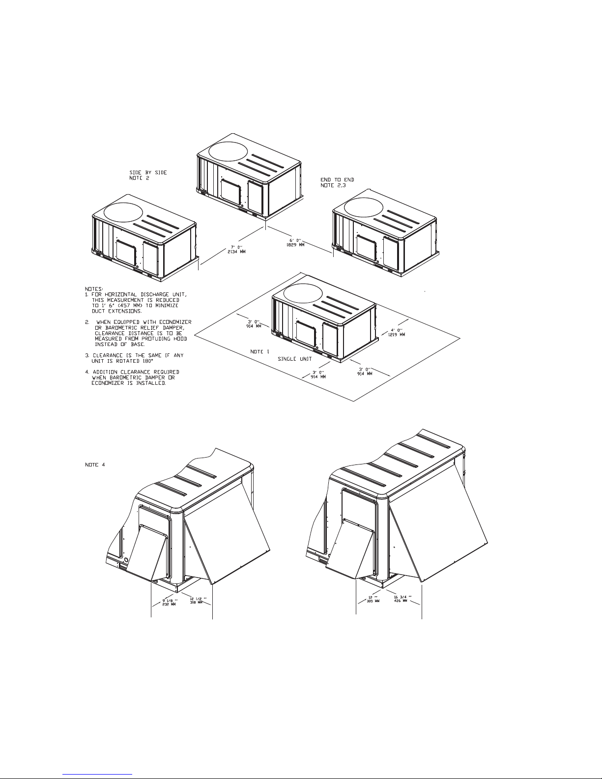
1. Manual outside air damper will
ship factory supplied within the
unit, but must be field installed.
2. High pressure control is standard
on all units.
3. Multi-stage, direct drive standard
on 3 to 5 ton models. Belt drive
standard on 6 to 8.5 ton standard
efficiency models. Variable speed
direct drive standard on 10 ton
model.
4. Economizer with barometric
relief is for downflow configured
units only. Order economizer
without barometric relief for
horizontal configuration.
Barometric relief for horizontal
configured units must be ordered
as field installed accessory.
5. Through-the-base electric
required when ordering
disconnect/circuit breaker
options.
6. Requires use of disconnect or
circuit breaker.
7. Standard metering devices are
TXVs.
8. The return air smoke detector
may not fit up or work properly on
the Precedent™ units when used
in conjunction with 3rd party
accessories such as bolt on heat
wheels, economizers and power
exhaust. Do not order the return
air smoke detectors when using
this type of accessory.
9. Requires hinged access panels.
10. Motorized outside air damper is
not available on Multi-Speed or
SZVAV (Single Zone Variable Air
Vol ume)
Variable Air Volume)
or MZVAV (Multi Zone
products.
11. Frostat™ standard on multispeed and SZVAV (single zone
variable air volume)
products.
12. Multi-speed indoor fan only
available on 8.5 and 10 ton
products.
13. Demand control ventilation
option includes wiring only. The
sensor is a field-installed
CO
2
only option.
14. SZVAV/MZVAV available only on
3 to 5 tons high efficiency and
SZVAV available on 8.5 and 10 ton
standard efficiency unit.
15. Must be used with BACnet® open
protocol.
16. Crankcase heater is standard on
all heat pumps.
RT-SVX23M-EN 7

General Information
Unit Inspection
As soon as the unit arrives at the job site
• Verify that the nameplate data matches the data on the
sales order and bill of lading (including electrical data).
• Verify that the power supply complies with the unit
nameplate specifications.
• Visually inspect the exterior of the unit, including the
roof, for signs of shipping damage.
If the job site inspection of the unit reveals damage or
material shortages, file a claim with the carrier
immediately. Specify the type and extent of the damage on
the “bill of lading” before signing.
• Visually inspect the internal components for shipping
damage as soon as possible after delivery and before
it is stored. Do not walk on the sheet metal base pans.
• If concealed damage is discovered, notify the carrier’s
terminal of damage immediately by phone and by
mail. Concealed damage must be reported within 15
days.
• Request an immediate joint inspection of the damage
by the carrier and the consignee. Do not remove
damaged material from the receiving location. Take
photos of the damage, if possible. The owner must
provide reasonable evidence that the damage did not
occur after delivery.
• Notify the appropriate sales representative before
installing or repairing a damaged unit.
Storage
Take precautions to prevent condensate from forming
inside the unit’s electrical compartments and motors if:
1. the unit is stored before it is installed; or,
2. the unit is set on the roof curb, and temporary heat is
provided in the building. Isolate all side panel service
entrances and base pan openings (e.g., conduit holes,
Supply Air and Return Air openings, and flue
openings) from the ambient air until the unit is ready
for start-up.
Note: Do not use the unit’s heater for temporary heat
without first completing the start-up procedure
detailed under the Unit Start-Up chapter.
The manufacturer will not assume any responsibility for
equipment damage resulting from condensate
accumulation on the unit’s electrical and/or mechanical
components.
Unit Nameplate
A Mylar unit nameplate is located on the unit’s corner
support next to the filter access panel. It includes the unit
model number, serial number, electrical characteristics,
refrigerant charge, as well as other pertinent unit data.
Compressor Nameplate
The nameplate for the compressors are located on the side
of the compressor.
Unit Description
Before shipment, each unit is leak tested, dehydrated,
charged with refrigerant and compressor oil, and run
tested for proper control operation.
The condenser coils are aluminum fin, mechanically
bonded to copper tubing.
Direct-drive, vertical discharge condenser fans are
provided with built-in thermal overload protection.
The ReliaTel™ Control Module is a microelectronic control
system that is referred to as “Refrigeration Module”
(RTRM). The acronym RTRM is used extensively
throughout this document when referring to the control
system network.
These modules through proportional/integral control
algorithms perform specific unit functions that governs
unit operation in response to; zone temperature, supply air
temperature, and/or humidity conditions depending on
the application. The stages of capacity control for these
units is achieved by starting and stopping the
compressors.
The RTRM is mounted in the control panel and is factory
wired to the respective internal components. The RTRM
receives and interpret information from other unit
modules, sensors, remote panels, and customer binary
contacts to satisfy the applicable request for cooling.
Economizer Control Actuator (Optional)
The ECA monitors the mixed air temperature, return air
temperature, minimum position setpoint (local or
remote), power exhaust setpoint, CO
ambient dry bulb/enthalpy sensor or comparative
humidity (return air humidity against ambient humidity)
sensors, if selected, to control dampers to an accuracy of
+/- 5% of stroke. The actuator is spring returned to the
closed position any time that power is lost to the unit. It is
capable of delivering up to 25 inch pounds of torque and
is powered by 24 VAC.
RTCI - ReliaTel™ Trane® Communication
Interface (Optional)
This module is used when the application calls for an
ICSTM building management type control system. It
allows the control and monitoring of the system through
an ICS panel. The module can be ordered from the factory
or ordered as a kit to be field installed. Follow the
installation instruction that ships with each kit when field
installation is necessary.
setpoint, CO2, and
2
8 RT-SVX23M-EN

General Information
RLCI - ReliaTel™ LonTalk® Communication
Interface (Optional)
This module is used when the application calls for an
ICSTM building management type control system that is
LonTalk. It allows the control and monitoring of the system
through an ICS panel. The module can be ordered from the
factory or ordered as a kit to be field installed. Follow the
installation instruction that ships with each kit when field
installation is necessary.
RBCI - ReliaTel™ BACnet® Communications
Interface (Optional)
This module is used when the application calls for an open
BACnet protocol. It allows the control and monitoring of
the system through an ICS panel. The module can be
ordered from the factory or as a kit to be field installed.
Follow the installation instructions that ships with each kit
when field installation is necessary.
RTOM – ReliaTel™ Options Module
The RTOM monitors the supply fan proving, clogged filter,
supply air temperature, exhaust fan setpoint, supply air
tempering, Frostat™ and smoke detector. Refer to system
input devices and functions for operation.
This module is standard on 10 ton products.
System Input Devices & Functions
The RTRM must have a zone sensor or thermostat input in
order to operate the rooftop unit. The flexibility of having
several mode capabilities depends upon the type of zone
sensor thermostat selected to interface with the RTRM.
The descriptions of the following basic Input Devices used
within the RTRM network are to acquaint the operator with
their function as they interface with the various modules.
Refer to the unit’s electrical schematic for the specific
module connections.
The following controls are available from the factory for
field installation.
Supply Fan Failure Input (Optional)
The Fan Failure Switch can be connected to sense indoor
fan operation:
FFS (Fan Failure Switch) If air flow through the unit is not
proven by the differential pressure switch connected to the
RTRM (factory set point 0.07 “w.c.) within 40 seconds
nominally, the RTRM will shut off all mechanical
operations, lock the system out, send a diagnostic to ICS,
and the SERVICE output will flash. The system will remain
locked out until a reset is initiated either manually or
through ICS.
Clogged Filter Switch (Optional)
The unit mounted clogged filter switch monitors the
pressure differential across the return air filters. It is
mounted in the filter section and is connected to the
RTOM. A diagnostic SERVICE signal is sent to the remote
RT-SVX23M-EN 9
panel if the pressure differential across the filters is at least
0.5" w.c. The contacts will automatically open when the
pressure differential across the filters decreases to
approximately 0.4" w.c. The clogged filter output is
energized when the supply fan is operating and the
clogged filter switch has been closed for at least 2 minutes.
The system will continue to operate regardless of the
status of the filter switch.
Note: On units equipped with factory installed MERV 13
filters, a clogged filter switch with different
pressure settings will be installed. This switch will
close when the differential pressure is
approximately 0.8' w.c. and open when the
differential falls to 0.7" w.c.
Condensate Drain Pan Overflow Switch
(Optional)
ReliaTel™ Option
This input incorporates the Condensate Overflow Switch
(COF) mounted on the drain pan and the ReliaTel Options
Module (RTOM). When the condensate level reaches the
trip point for 6 continuous seconds, the RTOM will shut
down all unit functions until the overflow condition has
cleared. The unit will return to normal operation after 6
continuous seconds with the COF in a non-tripped
condition. If the condensate level causes unit shutdown
more than 2 times in a 3 days period, the unit will be
locked-out of operation requiring manual reset of
diagnostic system through Zone Sensor or Building
Automation System (BAS). Cycling unit power will also
clear the fault.
Compressor Disable (CPR1/2)
This input incorporates the low pressure control (LPC) of
each refrigeration circuit and can be activated by opening
a field supplied contact installed on the LTB.
If this circuit is open before the compressor is started, the
compressor will not be allowed to operate. Anytime this
circuit is opened for 1 continuous second during
compressor operation, the compressor for that circuit is
immediately turned “Off”. The compressor will not be
allowed to restart for a minimum of 3 minutes should the
contacts close.
If four consecutive open conditions occur during the first
three minutes of operation, the compressor for that circuit
will be locked out, a diagnostic communicated to the
remote panel (if installed), and a manual reset will be
required to restart the compressor.
Low Pressure Control
When the LPC is opened for 1 continuous second, the
compressor for that circuit is turned off immediately. The
compressor will not be allowed to restart for a minimum
of 3 minutes.
If four consecutive open conditions occur during an active
call for cooling, the compressor will be locked out, a
diagnostic communicated to ICS™, if applicable, and a

General Information
manual reset required to restart the compressor. On dual
compressor units only the affected compressor circuit is
locked out.
High Pressure Control
The high pressure controls are wired in series between the
compressor outputs on the RTRM and the compressor
contactor coils. If the high pressure control switch opens,
the RTRM senses a lack of current while calling for cooling
and locks the compressor out.
If four consecutive open conditions occur during an active
call for cooling, the compressor will be locked out, a
diagnostic communicated to ICS™, if applicable, and a
manual reset required to restart the compressor. On dual
compressor units only the affected compressor circuit is
locked out.
Power Exhaust Control (Optional)
The power exhaust fan is started whenever the position of
the economizer dampers meets or exceed the power
exhaust setpoint when the indoor fan is on.
The setpoint panel is located in the return air section and
is factory set at 25%.
Lead/Lag Control (Dual Circuit Only)
Lead/Lag is a selectable input located on the RTRM. The
RTRM is configured from the factory with the Lead/Lag
control disabled. To activate the Lead/Lag function, simply
cut the wire connected to J3-8 at the RTRM. When it is
activated, each time the designated lead compressor is
shut off due to the load being satisfied, the lead
compressor or refrigeration circuit switches. When the
RTRM is powered up, i.e. after a power failure, the control
will default to the number one circuit compressor.
Zone Sensor Module (ZSM) (BAYSENS107*)
This electronic sensor features three system switch
settings (Heat, Cool, and Off) and two fan settings (On and
Auto). It is a manual changeover control with single
setpoint. (Cooling Setpoint Only)
Zone Sensor Module (ZSM) (BAYSENS109*)
This electronic sensor features four system switch settings
(Heat, Cool, Auto, and Off) and two fan settings (On and
Auto). It is a manual or auto changeover control with dual
setpoint capability. It can be used with a remote zone
temperature sensor BAYSENS077*.
Programmable Zone Sensor - (BAYSENS119*)
This 7 day programmable sensor features 2, 3 or 4 periods
for Occupied or Unoccupied programming per day. If the
power is interrupted, the program is retained in
permanent memory. If power is off for an extended period
of time, only the clock and day may have to be reset.
The zone sensor allows selection of 2, 3 or 4 system modes
(Heat, Cool, Auto, and Off), two fan modes (On and Auto).
It has dual temperature selection with programmable start
time capability.
The occupied cooling set point ranges between 45 and 98
degrees Fahrenheit. The heating set point ranges between
43 and 96 degrees Fahrenheit.
A liquid crystal display (LCD) displays zone temperature,
temperature set points, day of the week, time, and
operational mode symbols.
The Option Menu is used to enable or disable applicable
functions, i.e.; Morning Warm-up, Economizer minimum
position override during unoccupied status, Fahrenheit or
Centigrade, Supply air tempering, Remote zone
temperature sensor, 12/24 hour time display, Smart fan,
and Computed recovery.
During an occupied period, an auxiliary relay rated for 1.25
amps @ 30 volts AC with one set of single pole double
throw contacts is activated.
Status Inputs (4 Wires Optional). The ZSM can be wired to
receive four (4) operating status signals from the RTRM
(HEAT, COOL, SYSTEM “ON”, SERVICE). Four (4) wires
from the RTRM should be connected to the appropriate
terminals (7, 8, 9 & 10) on the ZSM.
Remote Zone Sensor (BAYSENS073*)
This electronic sensor features remote zone sensing and
timed override with override cancellation. It is used with a
Trane Integrated Comfort™ building management
system.
Remote Zone Sensor (BAYSENS074*)
This electronic sensor features single setpoint capability
and timed override with override cancellation. It is used
with a Trane Integrated Comfort™ building management
system.
Remote Zone Sensor (BAYSENS016*)
This bullet type temperature sensor can be used for;
outside air (ambient) sensing, return air temperature
sensing, supply air temperature sensing, remote
temperature sensing (uncovered). Wiring procedures vary
according to the particular application and equipment
involved. Refer to the unit’s wiring diagrams for proper
connections.
Remote Zone Sensor (BAYSENS077*)
This electronic sensor can be used with BAYSENS106*,
108*, 110*, 119* Remote Panels. When this sensor is wired
to a BAYSENS119* remote panel, wiring must be 18 AWG
shielded twisted pair (Belden 8760 or equivalent). Refer to
the specific remote panel for wiring details.
Wireless Zone Sensor (BAYSENS050*)
This electronic sensor features five system settings (Auto,
Off, Cool, Heat, and Emergency Heat) and with On and
Auto fan settings. It is a manual or auto changeover control
with dual setpoint capability. Other features include a
timed override function, lockable system settings, and
10 RT-SVX23M-EN

General Information
Fahrenheit or Celsius temperature display. Included with
the wireless zone sensor will be a receiver that is to be
mounted inside the unit, a mounting bracket, and a wire
harness.
High Temperature Sensor (BAYFRST001*)
This sensor connects to the RTRM Emergency Stop Input
located on the LTB and provides high limit “shutdown” of
the unit and requires a manual reset. The sensor is used to
detect high temperatures due to fire in the air conditioning
or ventilation ducts. The sensor is designed to mount
directly to the sheet metal duct. Each kit contains two
sensors. The return air duct sensor (X1310004001) is set to
open at 135°F. The supply air duct sensor (X1310004002) is
set to open at 240°F. The control can be reset after the
temperature has been lowered approximately 25°F below
the cutout setpoint.
Evaporator Frost Control
This input incorporates the Frostat™ control (FOS) located
on the indoor coil and can be activated by closing a field
supplied contact installed in parallel with the FOS.
If this circuit is closed before the compressor is started, the
compressor will not be allowed to operate. Anytime this
circuit is closed for 1 continuous second during
compressor operation, the compressor for that circuit is
immediately turned “Off”. The compressor will not be
allowed to restart for a minimum of 3 minutes should the
FOS open.
Frostat™ is standard on multi-speed indoor motors and
single zone VAV products (SZVAV).
Smoke Detector Sensor (Optional)
This sensor is only applicable on units equipped with a
RTOM. It provides high limit “shutdown” of the unit and
requires a manual reset. The sensor is used to detect
smoke due to fire in the air conditioning or ventilation
ducts.
Important:
• The supply air smoke detector samples supply air. The
return and plenum air smoke detectors sample return
air. The smoke detectors are designed to shut off the
unit if smoke is sensed in the supply air stream or
return air stream. This function is performed by
sampling the airflow entering the unit at the return air
opening. Follow the instructions provided below to
assure that the airflow through the unit is sufficient for
adequate sampling. Failure to follow these instructions
will prevent the smoke detectors from performing it's
design function.
• Airflow through the unit is affected by the amount of
dirt and debris accumulated on the indoor coil and
filters. To insure that airflow through the unit is
adequate for proper sampling by the return air smoke
detector, complete adherence to the maintenance
procedures, including recommended intervals
between filter changes, and coil cleaning is required.
• Periodic checks and maintenance procedures must be
performed on the smoke detector to insure that it will
function properly. For detailed instructions concerning
these checks and procedures, refer to the appropriate
section(s) of the smoke detector Installation and
Maintenance Instructions provided with the literature
package for this unit.
In order for the supply air smoke detector or return air
smoke detector to properly sense smoke in the supply air
stream or return air stream, the air velocity entering the
smoke detector unit must be between 500 and 4000 feet
per minute. Equipment covered in this manual will
develop an airflow velocity that falls within these limits
over the entire airflow range specified in the evaporator
fan performance tables.
Phase Monitoring protection
Precedent units with 3-phase power are equipped with
phase monitoring protection as standard. These devices
protect motors and compressors against problems caused
by phase loss, phase imbalance, and phase reversal
indication.
This sensor monitors voltage between the 3 conductors of
the 3 phase power supply. Two LED lights are provided.
The green light indicates that a balanced 3 phase supply
circuit is properly connected. The red light indicates that
unit operation has been prevented. There are two
conditions that will prevent unit operation. The power
supply circuit is not balanced with the proper phase
sequence of L1, L2, L3 for the 3 conductors of a 3 phase
circuit. The line to line voltage is not between 180 volts and
633 volts.
Human Interface - 5 Inch Color Touchscreen
(Optional)
The 5 inch Color Touchscreen Human Interface provides an
intuitive user interface to the rooftop unit that speeds up
unit commissioning, shortens unit troubleshooting times,
and enhances preventative maintenance measures. The
human interface includes several features including:
• Data trending capabilities by means of time series
graphs
• Historical alarm messages
• Real-time sensor measurements
• On board system setpoints
• USB port that enables the downloading of component
runtime information as well as trended historical
sensor data
• Customized reports
RT-SVX23M-EN 11

Pre-Installation
WARNI NG
Fiberglass Wool!
Exposition to glass wool fibers without all necessary
PPE equipment could result in cancer, respiratory, skin
or eye irritation, which could result in death or serious
injury. Disturbing the insulation in this product during
installation, maintenance or repair will expose you to
airborne particles of glass wool fibers and ceramic
fibers known to the state of California to cause cancer
through inhalation. You MUST wear all necessary
Personal Protective Equipment (PPE) including gloves,
eye protection, a NIOSH approved dust/mist respirator,
long sleeves and pants when working with products
containing fiberglass wool.
Precautionary Measures
• Avoid breathing fiberglass dust.
• Use a NIOSH approved dust/mist respirator.
• Avoid contact with the skin or eyes. Wear long-sleeved,
loose-fitting clothing, gloves, and eye protection.
• Wash clothes separately from other clothing: rinse
washer thoroughly.
• Operations such as sawing, blowing, tear-out, and
spraying may generate fiber concentrations requiring
additional respiratory protection. Use the appropriate
NIOSH approved respiration in these situations.
First Aid Measures
Eye Contact - Flush eyes with water to remove dust. If
symptoms persist, seek medical attention.
Skin Contact - Wash affected areas gently with soap and
warm water after handling.
12 RT-SVX23M-EN
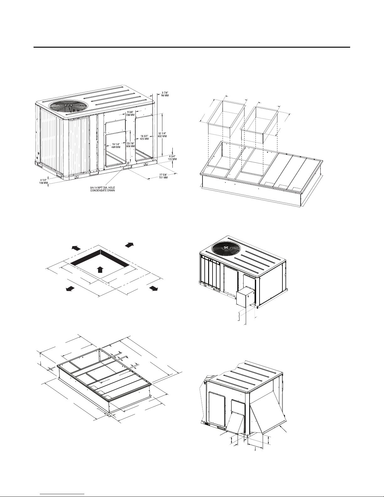
Dimensions and Weights
WSC036-048H, W/DHC036H Units
WSC060-120E/H, W/DHC048-060H Units
Figure 1. Typical installation clearances for single & multiple unit applications
RT-SVX23M-EN 13
Dimensions and Weights
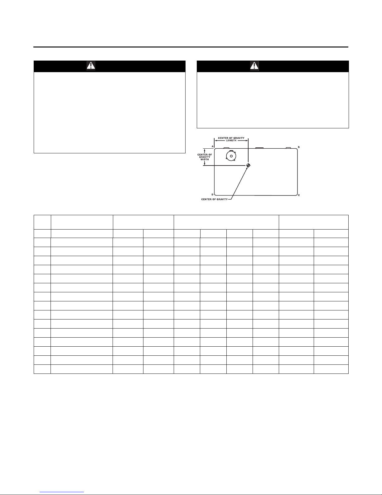
WARN ING
Heavy Objects!
Failure to follow instructions below or properly lift unit
could result in unit dropping and possibly crushing
operator/technician which could result in death or
serious injury, and equipment or property-only damage.
Ensure that all the lifting equipment used is properly
rated for the weight of the unit being lifted. Each of the
cables (chains or slings), hooks, and shackles used to
Improper Unit Lift!
Failure to properly lift unit could result in unit dropping
and possibly crushing operator/technician which could
result in death or serious injury, and equipment or
property-only damage. Test lift unit approximately 24
inches to verify proper center of gravity lift point. To
avoid dropping of unit, reposition lifting point if unit is
not level.
WARNI NG
lift the unit must be capable of supporting the entire
weight of the unit. Lifting cables (chains or slings) may
not be of the same length. Adjust as necessary for even
unit lift.
Table 1. Maximum unit & corner weights (lbs) and center of gravity dimensions (in.)
Unit
Tons Model No. Shipping Net A B C D Length Width
3 WSC036H 612 507 144 122 110 130 32 21
4 WSC048H 645 540 165 131 108 136 31 20
5 WSC060H 777 682 228 177 114 163 38 22
6 WSC072E/H 835 740 235 196 140 168 40 22
7.5 WSC090E/H 902 804 255 217 153 180 41 22
7.5 WSC092H 894 796 252 204 163 177 41 23
8.5 WSC102H 927 829 286 183 195 164 40 23
10 WSC120E 1388 1199 342 328 259 270 49 28
10 WSC120H 948 850 303 170 218 159 40 24
3 WHC036H 619 514 142 120 111 142 31 22
4 WHC048H 768 673 222 175 114 162 38 22
5 WHC060H 773 678 225 176 114 162 38 22
3 DHC036H 658 553 145 137 125 145 33 22
4 DHC048H 845 750 234 192 146 178 40 23
5 DHC060H 849 754 235 193 147 179 40 23
(a) Weights are approximate.
(b) Corner weights are given for information only.
Maximum Model
Weights
(a)
Corner Weights
(b)
Center of Gravity (in.)
14 RT-SVX23M-EN
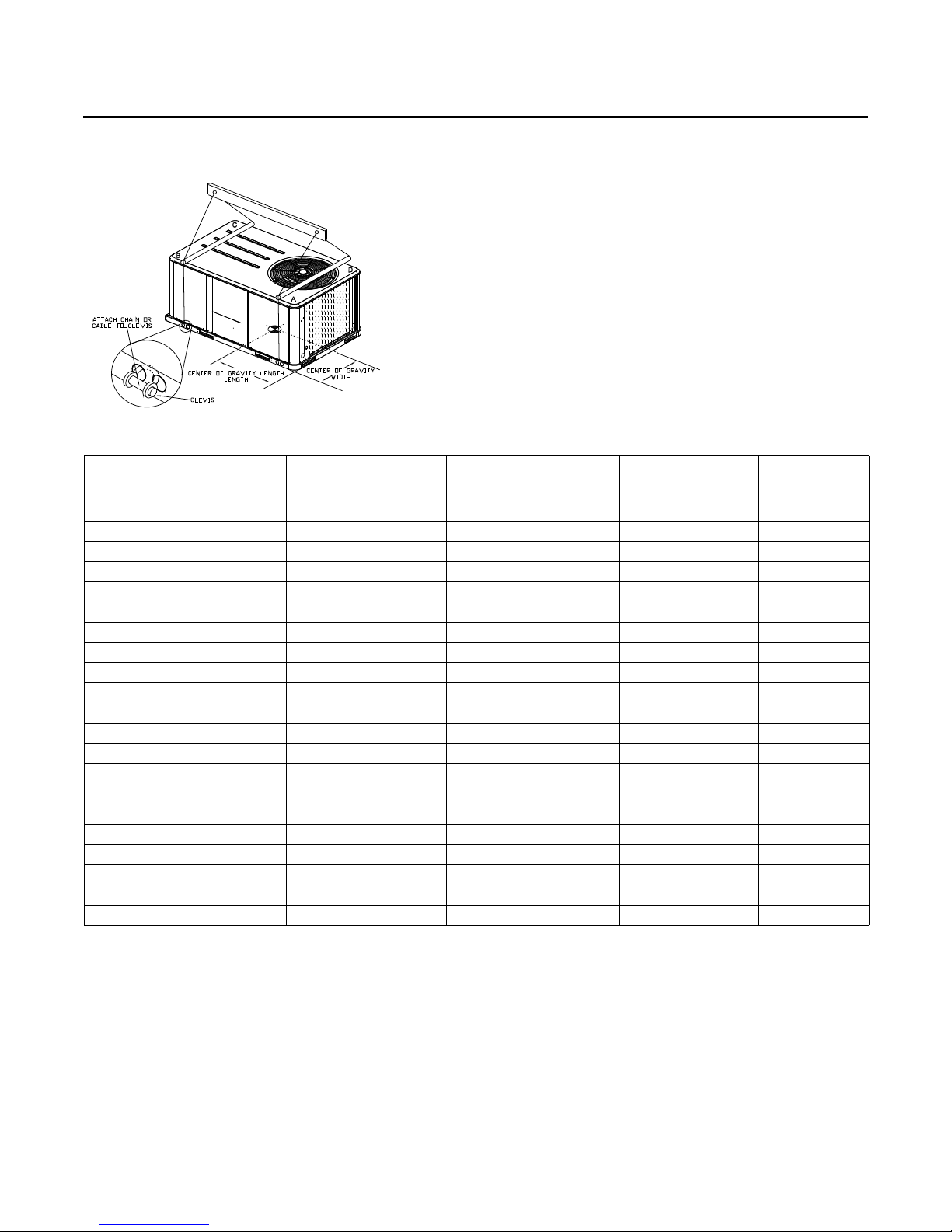
Figure 2. Rigging and center-of-gravity data
Dimensions and Weights
Table 2. Factory installed options (fiops)/accessory net weights (lbs)
WSC036H-048H,
W/DHC036H
Net Weight
Accessory
460V/575V IDM Transformer
Barometric Relief 7 10 10 10
Coil Guards 12 20 20 30
Economizer 26 36 36 36
Electric Heaters
Hinged Doors 11 12 12 12
Low Leak Economizer 68 93 93 93
Manual Outside Air Damper 16 26 26 26
Motorized Outside Air Damper 20 30 30 30
Oversized Motor 8 8 8 —
Powered Convenience Outlet 38 38 38 50
Powered Exhaust 40 80 80 80
Roof Curb 61 78 78 89
Smoke Detector, Supply 5 5 5 5
Smoke Detector, Return 7 7 7 7
Stainless Steel Heat Exchanger
Through-the-Base Electrical 8 13 8 13
Through-the-Base Gas(e) 55——
Unit Mounted Circuit Breaker 5 5 5 5
Unit Mounted Disconnect 5 5 5 5
(a) Weights for options not listed are <5 lbs.
(b) Net weight should be added to unit weight when ordering factory-installed accessories.
(c) Applicable to W/DHC 460/575V units.
(d) Applicable to heat pump units only (W*C).
(e) Applicable to dual fuel units only (D*C).
(d)
(c)
(e)
3 to 4 Tons
29 29 — —
15 30 30 40
45——
W/DHC048-060H
Net Weight
4 to 5 Tons
(a),(b)
WSC060H,
WSC072H-120E/H
Net Weight
6 to 10 Tons
W/DHC120H
Net Weight
10 Tons
RT-SVX23M-EN 15
Dimensions and Weights
EVAPORATOR SECTION
ACCESS PANEL
ALTERNATE
CONDENSATE DRAIN
3/4 - 14 NPT DIA. HOLE
1/2 NPT GAS CONNECTION
TOP PANEL
CONDENSER FAN
CONDENSER COIL
UNIT CONTROL WIRE
7/8” (22 MM) DIA. HOLE
SERVICE GAUGE PORT ACCESS
1 3/8” (35 MM) DIA. HOLE
UNIT CONTROL WIRE
2” (51 MM) DIA. HOLE
40 7/8”
1038 MM
4 1/4”
108 MM
69 7/8”
1749 MM
42 1/4”
1073 MM
23 9/16”
598 MM
5 5/8”
143 MM
9 5/8”
244 MM
CONTROL AND COMPRESSOR
ACCESS PANEL
44 1/4”
1124 MM
7 5/8”
194 MM
5 9/16”
141 MM
4 1/4”
108 MM
20 1/4”
514 MM
THROUGH
THE BASE GAS
(Y_C/DHC MODELS ONLY)
THROUGH
THE BASE
ELECTRICAL
SUPPLY
RETURN
TBU CONDENSATE
3 5/8”
92 MM
14”
356 MM
9 1/4”
235 MM
15 1/2”
394 MM
4”
102 MM
24”
610 MM
18”
457 MM
27 9/16”
701 MM
4 3/16”
106 MM
4 9/16”
116 MM
23 1/2”
597 MM
2 13/16”
71 MM
6 1/2”
165 MM
3 11/16”
94 MM
4 7/8”
124 MM
5 1/16”
128 MM
9 15/16”
253 MM
SUPPLY
RETURN
3/4-14 NPT
DRAIN CONNECTION
CONDENSER COIL
17 1/4”
438 MM
8 7/8”
225 MM
13 1/4”
337 MM
23 1/4”
591 MM
3 3/16”
81 MM
14 3/4”
375 MM
4 3/4”
121 MM
CLEARANCE 36” (914 MM)
CLEARANCE 48” (1219 MM)
TYPICAL ROOF OPENING
CLEARANCE 36” (914 MM)
CLEARANCE FROM
TOP OF UNIT 72”
CLEARANCE
HORIZONTAL FLOW - 18” (457 MM)
DOWNFLOW 36” (914 MM)
68 3/16”
1732 MM
40”
1016 MM
37”
940 MM
44 1/2”
1130 MM
7
CLEARANCE 36” (914 MM)
CLEARANCE 36” (914 MM) FOR DOWNFLOW
CLEARANCE 18” (457 MM) FOR HORIZONTAL
CLEARANCE 36” (914 MM)
CLEARANCE 48” (1219 MM)
RETURN
SUPPLY
14”
356 MM
37 7/16”
951 MM
25 3/16”
640 MM
1 3/4”
44 MM
65 13/16”
1670 MM
1 3/4”
44 MM
14 9/16”
370 MM
8 3/8”
213 MM
61 13/16”
1568 MM
65 3/16”
1656 MM
16 3/4”
425 MM
2”
51 MM
2”
51 MM
40 7/8”
1038 MM
41 7/16”
1053 MM
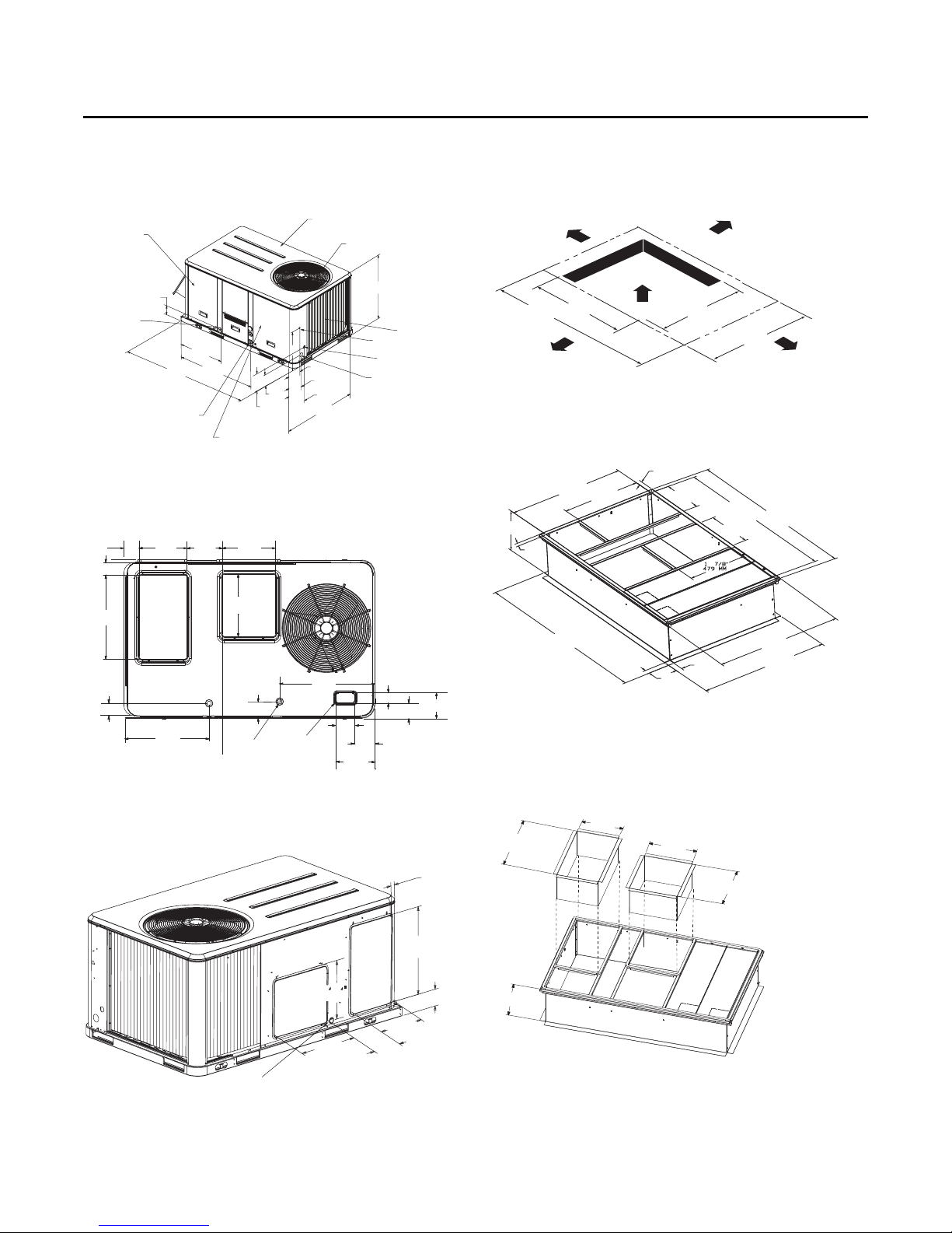
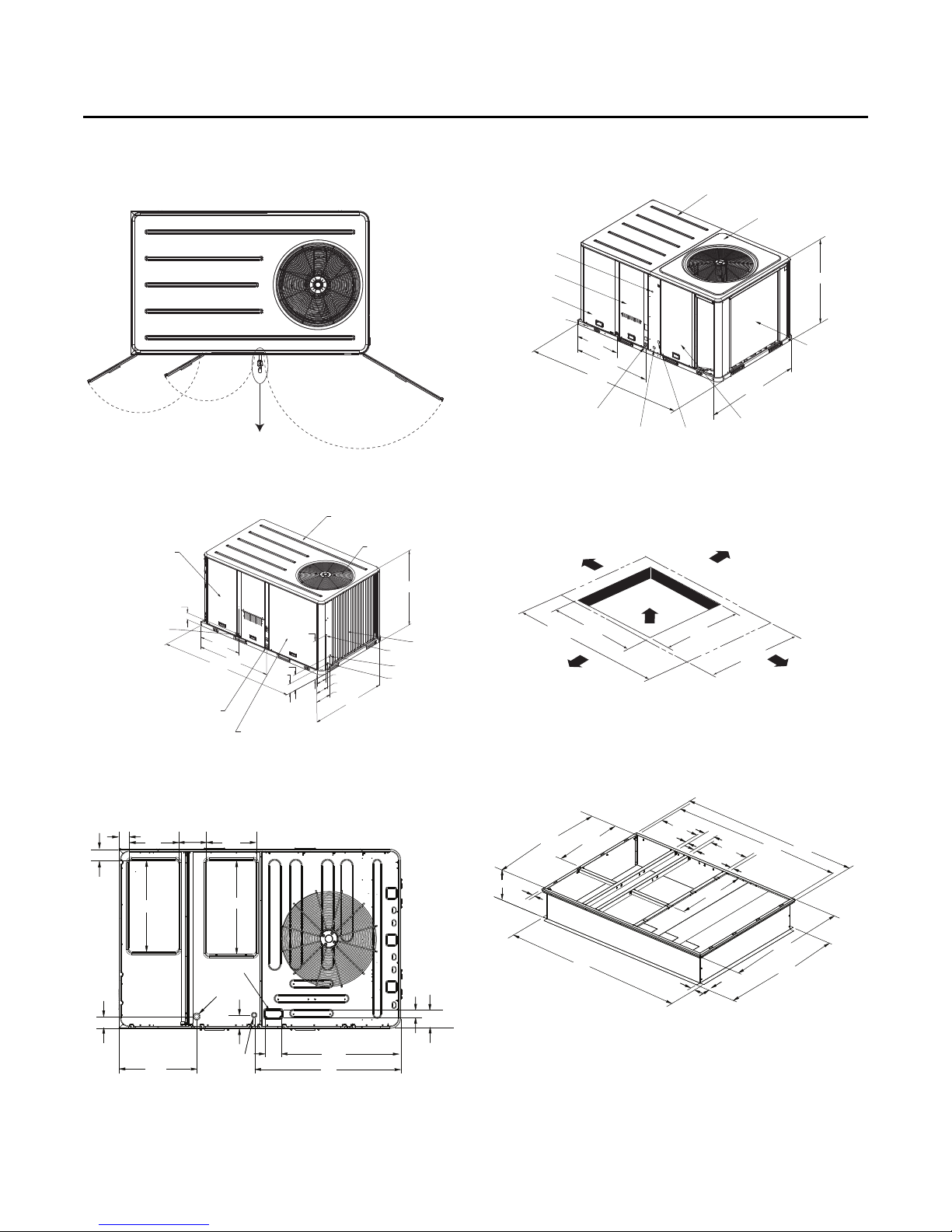
Figure 3. Heat pump - 3 to 4 tons standard efficiency, 3
ton high efficiency
Note: 2” electrical connection: single point power when heat installed
(WSC, W/DHC)
Figure 4. Heat pump - 3 to 4 tons standard efficiency, 3
ton high efficiency - downflow airflow supply/
return - through-the-base utilities
Figure 6. Heat pump - 3 to 4 tons standard efficiency, 3
ton high efficiency - unit clearance and roof
opening
Figure 7. Heat pump - 3 to 4 tons standard efficiency, 3
ton high efficiency - roof curb
Figure 5. Heat pump - 3 to 4 tons standard efficiency, 3
ton high efficiency - horizontal airflow supply/
return
16 RT-SVX23M-EN
Figure 8. Heat pump - 3 to 4 tons standard efficiency, 3
ton high efficiency - downflow duct
connections - field fabricated
Note: Reference tabular information for duct clearance to combustible
materials in the application consideration chapter.
14 1/16”
24 3/8”
(619 MM)
14”
(356 MM)
(357 MM)
RETURN
16 3/16”
(411 MM)
SUPPLY
17 1/16”
(433 MM)
ALL FLANGES 1 1/4” (32 MM)
Dimensions and Weights
6 15/16”
176 MM
9 1/8”
232 MM
17 7/8”
454 MM
16”
406 MM
22 1/4”
565 MM
Applicable to
Y_C models only
EVAPORATOR SECTION
ACCESS PANEL
ALTERNATE CONDENSATE DRAIN
CONNECTION 3/4 - 14 NPT DIA. HOLE
4 1/4”
108 MM
27 5/8”
701 MM
47 7/8”
1216 MM
88 5/8”
2251 MM
18 1/2”
470 MM
9 5/8”
244 MM
5 5/8”
143 MM
1/2 NPT GAS CONNECTION
[60 MBh, 80 MBh, 100 MBh, 120 MBh,
130 MBh (not applicable to DHC)]
3/4 NPT GAS CONNECTION
(130 MBh (DHC only), 150 MBh, 200 MBh, 250 MBh)
CONTROL AND COMPRESSOR
ACCESS PANEL
4 1/4”
104 MM
5 5/8”
143 MM
7 5/8”
194 MM
53 1/4”
1353 MM
TOP PANEL
CONDENSER FAN
CONDENSER COIL
UNIT CONTROL WIRE
7/8” (22 MM) DIA. HOLE
SERVICE GAUGE PORT ACCESS
1 3/8” (35 MM) DIA. HOLE
UNIT POWER WIRE
1 3/8” (35 MM) DIA. HOLE
3 5/8”
92 MM
17 1/2”
444 MM
4”
102 MM
9 7/8”
251 MM
17 1/2”
444 MM
32 1/8”
816 MM
RETURN
SUPPLY
33”
838 MM
4 1/8”
104 MM
27 5/8”
701 MM
THROUGH THE
BASE CONDENSATE
40 3/4”
1035 MM
THROUGH THE
BASE ELECTRICAL
5 7/8”
149 MM
5”
127 MM
10 7/8”
276 MM
3 3/4”
95 MM
2 3/4”
71 MM
6 1/2”
165 MM
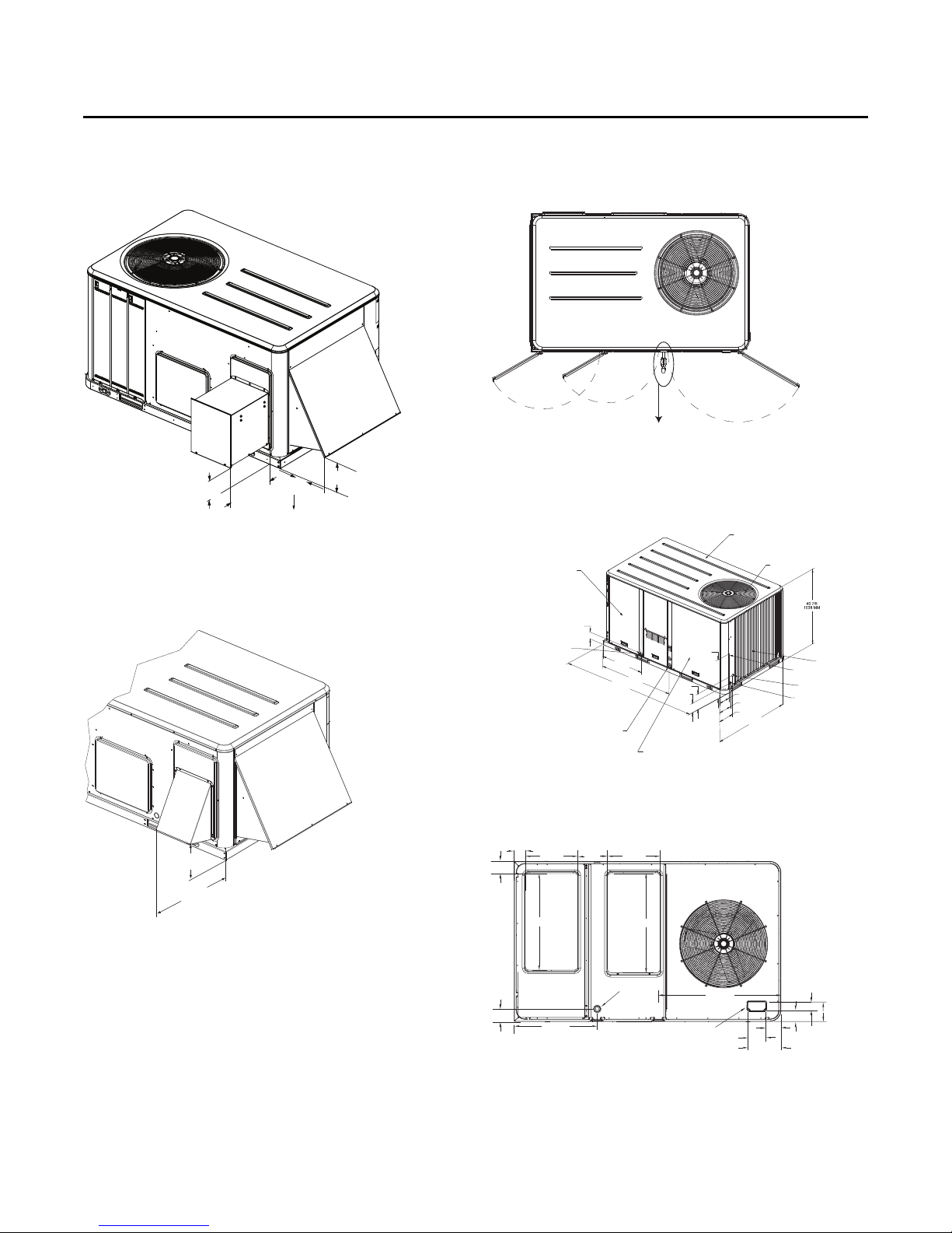
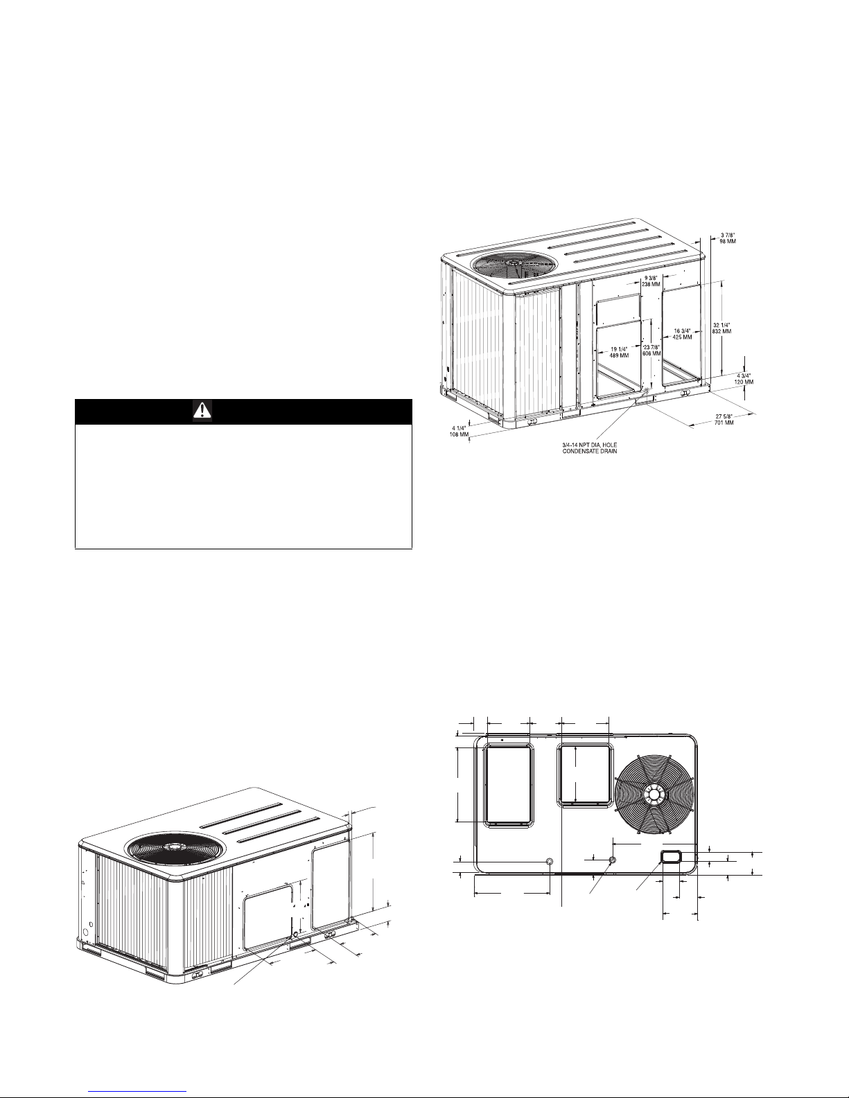
Figure 9. Heat pump - 3 to 4 tons standard efficiency, 3
ton high efficiency - economizer, manual or
motorized fresh air damper; power exhaust
16 1/4”
159 MM
6 3/16”
157 MM
12 1/2”
16 1/2”
318 MM
419 MM
Dimensions extends to 16 1/2"/419 MM
when powered exhaust is coupled
with low leak economizer
Figure 10. Heat pump 3 to 4 tons standard efficiency, 3
ton high efficiency - economizer & barometric
relief damper hood
Figure 11. Heat pump - 3 to 4 tons standard efficiency, 3
ton high efficiency - swing diameter for
hinged door(s) option
Figure 12. Heat pump - 5 to 10 tons standard efficiency, 4
to 5 ton high efficiency
Note: 2” electrical connection: single point power when heat installed
(WSC, W/DHC)
RT-SVX23M-EN 17
Figure 13. Heat pumps - 5 to 10 tons standard efficiency,
4 to 5 ton high efficiency - downflow airflow
supply/return - through-the-base utilities
Dimensions and Weights
Supply
Return
CLEARANCE 36” (914 MM)
CLEARANCE FROM
TOP OF UNIT 72”
TYPICAL ROOF OPENING
CLEARANCE 48” (1219 MM)
CLEARANCE 36” (914 MM)
CLEARANCE
HORIZONTAL FLOW - 18” (457 MM)
DOWNFLOW - 36” (914 MM)
53 1/4”
1352 MM
46”
1168 MM
46”
1168 MM
88 5/8”
2251 MM
CLEARANCE 36” (914 MM)
CLEARANCE 36” (914 MM)
CLEARANCE 48” (1219 MM)
CLEARANCE 36” (914 MM) FOR DOWNFLOW
CLEARANCE 18” (457 MM) FOR HORIZONTAL
46 3/8”
1178 MM
1 3/4”
44 MM
46 3/8”
1178 MM
34 3/8”
873 MM
84 1/2”
2146 MM
2”
51 MM
34 3/8”
873 MM
1”
25 MM
49 7/8”
1267 MM
50 3/8”
1280 MM
2”
51 MM
83 7/8”
2130 MM
80 1/2”
2045 MM
18 1/2”
470 MM
1”
25 MM
6 5/8”
168 MM
18 1/4”
470 MM
1”
25 MM
RETURN
SUPPLY
BAROMETRIC RELIEF HOOD
ECONOMIZER HOOD
Dimensions extends to 21 5/8"/549 MM
when powered exhaust is coupled
with low leak economizer
7 3/4”
198 MM
12”
304 MM
16 3/4”
425 MM
6 7/8”
175 MM
Figure 14. Heat pumps - 5 to 10 tons standard efficiency,
4 to 5 ton high efficiency - horizontal airflow
supply and return
Figure 15. Heat pumps - 5 to 10 tons standard efficiency,
4 to 5 ton high efficiency - unit clearance and
roof opening
Figure 17. Heat pumps - 5 to 10 tons standard efficiency,
4 to 5 ton high efficiency - downflow duct
connections field fabricated
Note: Reference tabular information for duct clearance to combustible
materials in the Installation chapter.
17 3/4”
33 3/4”
857 MM
451MM
17 3/4”
451MM
33 3/4”
857 MM
ALL FLANGES 1 1/4" (31 MM)
RETURN
SUPPLY
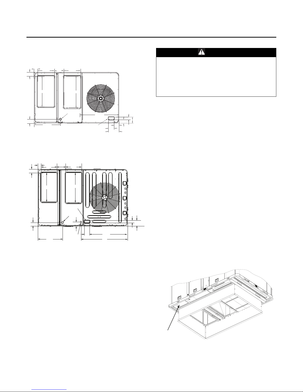
Figure 18. Heat pumps - 5 to 10 tons standard efficiency,
4 to 5 ton high efficiency - power exhaust
Figure 16. Heat pumps - 5 to 10 tons standard efficiency,
4 to 5 ton high efficiency - roof curb
18 RT-SVX23M-EN
6 11/16”
16 1/2”
170 MM
419 MM
Figure 19. Heat pumps - 5 to 10 tons standard efficiency,
4 to 5 ton high efficiency - economizer, manual
or motorized fresh air damper
BAROMETRIC RELIEF HOOD
7 3/4”
198 MM
12”
16 3/4”
304 MM
425 MM
Dimensions extends to 21 5/8"/549 MM
when powered exhaust is coupled
with low leak economizer
6 7/8”
175 MM
ECONOMIZER HOOD
Dimensions and Weights
21 3/8”
543 MM
17”
432 MM
34 5/8”
879 MM
Applicable to
Y_C/DHC models only
1/2 NPT GAS CONNECTION
(80 mbh, 120 mbh)
3/4 NPT GAS CONNECTION
(150 mbh, 200 mbh, 250 mbh)
(YC MODELS)
EVAPORATOR SECTION
ACCESS PANEL
ALTERNATE CONDENSATE DRAIN
CONNECTION 3/4 - 14 NPT DIA. HOLE
4 1/4”
108 MM
27 5/8”
701 MM
88 5/8”
2251 MM
47 7/8”
1216 MM
24 1/2”
622 MM
9 5/8”
244 MM
5 5/8”
143 MM
4 1/4”
108 MM
5 5/8”
143 MM
7 5/8”
194 MM
53 1/4”
1353 MM
CONDENSER COIL
UNIT CONTROL WIRE
7/8” (22 MM) DIA. HOLE
SERVICE GAUGE PORT ACCESS
1 3/8” (35 MM) DIA. HOLE
UNIT CONTROL WIRE
1 3/8” (35 MM) DIA. HOLE
46 7/8”
1190 MM
CONDENSER FAN
TOP PANEL
CONTROL AND COMPRESSOR
ACCESS PANEL
RETURNRETURN
SUPPLYSUPPLY
3 5/8”3 5/8”
92 MM92 MM
17 1/2”17 1/2”
444 MM444 MM
9 7/8”9 7/8”
251 MM251 MM
17 1/2”17 1/2”
444 MM444 MM
32 1/8”32 1/8”
816 MM816 MM
33”33”
838 MM838 MM
4”4”
102 MM102 MM
THROUGH THE THROUGH THE
BASE ELECTRICALBASE ELECTRICAL
THROUGH THE THROUGH THE
BASE CONDENSATEBASE CONDENSATE
4 5/8”4 5/8”
119 MM119 MM
THROUGH THETHROUGH THE
BASE GASBASE GAS
5 7/8”5 7/8”
149 MM149 MM
27 5/8”27 5/8”
701 MM701 MM
42 3/16”42 3/16”
1072 MM1072 MM
6 3/8”6 3/8”
163 MM163 MM
2 3/4”2 3/4”
71 MM71 MM
51 3/16”51 3/16”
1316 MM1316 MM
4 1/8”4 1/8”
104 MM104 MM
UNIT CONTROL WIRE
7/8” (22 MM) DIA. HOLE
CONTROL BOX SECTION
ACCESS PANEL
EVAPORATOR SECTION
ACCESS PANEL
ALTERNATE CONDENSATE DRAIN
CONNECTION 3/4 - 14 NPT DIA. HOLE
1/2 NPT GAS CONNECTION
(120 MBh)
3/4 NPT GAS CONNECTION
(150 MBh, 200 MBh, 250 MBh)
27 5/8”
701 MM
47 7/8”
1216 MM
99 11/16”
2532 MM
63 3/16”
1605 MM
50 7/8”
1292 MM
UNIT POWER WIRE
1 3/8” (35 MM) DIA. HOLE
SERVICE GAUGE
PORT ACCESS
1 3/8” (35 MM) DIA. HOLE
COMPRESSOR ACCESS PANEL
CONDENSER COIL
OUTDOOR TOP PANEL
INDOOR TOP PANEL
CLEARANCE 36” (914 MM)
CLEARANCE
HORIZONTAL FLOW - 18” (457 MM)
DOWNFLOW 36” (914 MM)
TYPICAL ROOF OPENING
CLEARANCE 36” (914 MM)
CLEARANCE 48” (1219 MM)
CLEARANCE FROM
TOP OF UNIT 72”
63 3/16”
1605 MM
46”
1168 MM
46”
1168 MM
99 11/16”
2532 MM
56 3/8”
1432 MM
14”
356 MM
1 3/4”
44 MM
34 3/8”
873 MM
18 1/2”
470 MM
1”
25 MM
6 5/8”
168 MM
1”
25 MM
18 1/2”
470 MM
1”
25 MM
80 1/2”
2045 MM
83 7/8”
2130 MM
CLEARANCE 36” (914 MM) FOR DOWNFLOW
CLEARANCE 18” (457 MM) FOR HORIZONTAL
34 3/8”
873 MM
59 7/8”
1521 MM
60 3/8”
1534 MM
2”
51 MM
2”
51 MM
84 1/2”
2146 MM
Figure 20. Heat pumps - 5 to 10 tons standard efficiency,
4 to 5 ton high efficiency - swing diameter for
hinged door(s) option
Figure 21. Heat pump - 7.5 to 10 tons standard efficiency
Figure 23. Heat pump - 10 tons high efficiency
Note: 2" Electrical Connection: Single Point Power When Heat Installed.
Figure 24. Heat pump - 10 tons high efficiency - unit
clearance and roof opening
Figure 22. Heat pump - 10 tons high efficiency -
downflow airflow supply/return through-thebase utilities
RT-SVX23M-EN 19
Figure 25. Heat pump - 10 tons high efficiency - roof curb
Note: 2" Electrical Connection: Single Point Power When Heat Installed
18 1/2”
470 MM
1”
25 MM
2”
51 MM
356 MM
56 3/8”
34 3/8”
1432 MM
873 MM
14”
1 3/4”
44 MM
84 1/2”
2146 MM
6 5/8”
168 MM
1”
25 MM
34 3/8”
873 MM
2”
51 MM
CLEARANCE 36” (914 MM) FOR DOWNFLOW
CLEARANCE 18” (457 MM) FOR HORIZONTAL
80 1/2”
18 1/2”
2045 MM
470 MM
1”
25 MM
59 7/8”
1521 MM
60 3/8”
1534 MM
83 7/8”
2130 MM
Installation
SUPPLY
RETURN
3/4-14 NPT
DRAIN CONNECTION
CONDENSER COIL
17 1/4”
438 MM
8 7/8”
225 MM
13 1/4”
337 MM
23 1/4”
591 MM
3 3/16”
81 MM
14 3/4”
375 MM
4 3/4”
121 MM
Foundation
Horizontal Units
If the unit is installed at ground level, elevate it above the
snow line. Provide concrete footings at each support
location with a “full perimeter” support structure or a slab
foundation for support. For the unit’s operating and point
loading weights when constructing a footing foundation,
refer to the maximum unit/corner weights table in the
weights section of this manual.
If anchoring is required, anchor the unit to the slab using
hold down bolts or isolators. Isolators should be installed
to minimize the transmission of vibrations into the
building.
WARNING
Risk of Roof Collapsing!
Failure to ensure proper structural roof support could
cause the roof to collapse, which could result in death
or serious injury and property damage. Confirm with a
structural engineer that the roof structure is strong
enough to support the combined weight of the
roofcurb and the unit. Refer to the weights section for
typical unit and curb weights.
For rooftop applications, ensure the roof is strong enough
to support the combined unit and support structural
weight. If anchoring is required, anchor the unit to the roof
with hold-down bolts or isolators.
Check with a roofing contractor for proper waterproofing
procedures.
Ductwork
Supply and return air openings as viewed from the rear of
the unit are shown in the following drawings.
Figure 26. Heat pump - 3 to 4 tons standard efficiency, 3
ton high efficiency - horizontal airflow supply/
return
Figure 27. Heat pumps - 5 to 10 tons standard efficiency,
4 to 5 ton high efficiency - horizontal airflow
supply and return
Return
Supply
Supply and return air openings as viewed from a
downflow configuration to 5 are shown in the following
drawings.
Elbows with turning vanes or splitters are recommended
to minimize air noise due to turbulence and to reduce static
pressure.
When attaching the ductwork to the unit, provide a watertight flexible connector at the unit to prevent operating
sounds from transmitting through the ductwork.
All outdoor ductwork between the unit and the structure
should be weather proofed after installation is completed.
Figure 28. Heat pump - 3 to 4 tons standard efficiency, 3
ton high efficiency - downflow airflow supply/
return - through-the-base utilities
3 5/8”
92 MM
102 MM
610 MM
24”
4”
RETURN
14”
356 MM
9 1/4”
235 MM
15 1/2”
394 MM
18”
457 MM
SUPPLY
20 RT-SVX23M-EN
4 3/16”
106 MM
TBU CONDENSATE
23 1/2”
597 MM
4 9/16”
116 MM
THROUGH
THE BASE GAS
(Y_C/DHC MODELS ONLY)
ELECTRICAL
27 9/16”
701 MM
THROUGH
THE BASE
4 7/8”
124 MM
9 15/16”
253 MM
5 1/16”
128 MM
2 13/16”
71 MM
3 11/16”
94 MM
6 1/2”
165 MM
Installation
3 5/8”
92 MM
17 1/2”
444 MM
4”
102 MM
9 7/8”
251 MM
17 1/2”
444 MM
32 1/8”
816 MM
RETURN
SUPPLY
33”
838 MM
4 1/8”
104 MM
27 5/8”
701 MM
THROUGH THE
BASE CONDENSATE
40 3/4”
1035 MM
THROUGH THE
BASE ELECTRICAL
5 7/8”
149 MM
5”
127 MM
10 7/8”
276 MM
3 3/4”
95 MM
2 3/4”
71 MM
6 1/2”
165 MM
RETURNRETURN
SUPPLYSUPPLY
3 5/8”3 5/8”
92 MM92 MM
17 1/2”17 1/2”
444 MM444 MM
9 7/8”9 7/8”
251 MM251 MM
17 1/2”17 1/2”
444 MM444 MM
32 1/8”32 1/8”
816 MM816 MM
33”33”
838 MM838 MM
4”4”
102 MM102 MM
THROUGH THE THROUGH THE
BASE ELECTRICALBASE ELECTRICAL
THROUGH THE THROUGH THE
BASE CONDENSATEBASE CONDENSATE
4 5/8”4 5/8”
119 MM119 MM
THROUGH THETHROUGH THE
BASE GASBASE GAS
5 7/8”5 7/8”
149 MM149 MM
27 5/8”27 5/8”
701 MM701 MM
42 3/16”42 3/16”
1072 MM1072 MM
6 3/8”6 3/8”
163 MM163 MM
2 3/4”2 3/4”
71 MM71 MM
51 3/16”51 3/16”
1316 MM1316 MM
4 1/8”4 1/8”
104 MM104 MM
Base Alignment Bracket
Figure 29. Heat pumps - 5 to 10 tons standard efficiency,
4 to 5 ton high efficiency - downflow airflow
supply/return - through-the-base utilities
Figure 30. Heat pump - 10 tons high efficiency -
downflow airflow supply/return through-thebase utilities
Roof Curb
The roof curbs for these units consists of a "full perimeter"
enclosure to support the unit just inside of the unit base
rail. The WSC120E, W/DHC120H unit contains a support
base alignment rail and will extend past the end of the roof
curb as shown in figures below.
Before installing any roof curb, verify;
• It is the correct curb for the unit,
• The necessary gaskets and hardware are included,
• The purposed installation location provides the
required clearance for proper operation.
• Insure that the curb is level and square. The top surface
RT-SVX23M-EN 21
of the curb must be true to assure an adequate curb-tounit seal.
WARNING
Combustible Materials!
Failure to maintain proper clearance between the unit
heat exchanger, vent surfaces and combustible
materials could cause a fire which could result in death
or serious injury or property damage. Refer to unit
nameplate and installation instructions for proper
clearances.
Verify that appropriate materials were used in the
construction of roof and ductwork. Combustible materials
should not be used in the construction of ductwork or roof
curb that is in close proximity to heater elements or any
hot surface. Any combustible material on the inside of the
unit base should be removed and replaced with
appropriate material.
Step-by-step curb assembly and installation instructions
ship with each accessory roof curb kit. Follow the
instructions carefully to assure proper fit-up when the unit
is set into place.
Note: To assure proper condensate flow during
operation, as well as proper operation of the
condensate overflow switch (if equipped), the unit
and curb must be level.
If the unit is elevated, a field constructed catwalk around
the unit is strongly recommended to provide easy access
for unit maintenance and service.
Recommendations for installing the Supply Air and Return
Air ductwork joining the roof curb are included in the curb
instruction booklet. Curb ductwork must be fabricated and
installed by the installing contractor before the unit is set
into place.
Note: For sound consideration, cut only the holes in the
roof deck for the ductwork penetrations. Do not cut
out the entire roof deck within the curb perimeter.
Figure 31. View for base to roof curb alignment
WSC120E, W/DHC120H on 50 x 84 roof curb
 Loading...