

Page 1
VSD Output Monitoring
The VSD output monitoring kits (for variable speed inverter drive units) are designed to
provide a speed (output) feedback signal to the control and monitoring system.
This feature enables the management system to optimize efficiency by accurately monitoring
the performance and behavior of a variable speed drive compressor unit.
Specification:
Variable Speed Drive AC Inverter type (not suitable for DC or SR drives)
Drive Frequency Range 3Hz to 400Hz
Drive Operating Voltage 200Vac to 575Vac
Compressor Motor Size 7.5kW to 500kW
The VSD output monitoring kit can be fitted to an X - Series Automation CX or VSD Box.
Kit Selection
There are two kits available; each kit is designed to cover a different current range.
To establish the correct kit for an application:
1) Determine the compressor motor kW rating (establish from motor data plate)
2) Determine the motor operating voltage (establish from motor data plate)
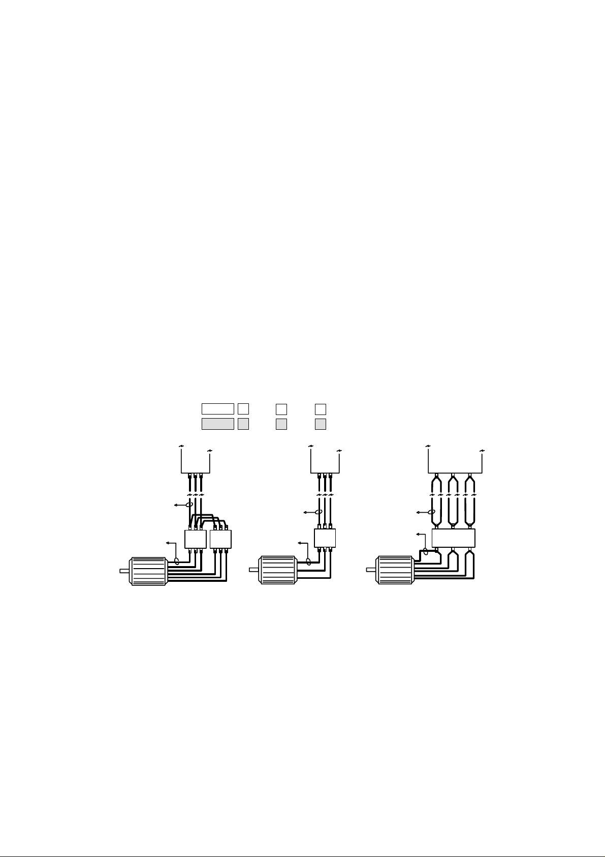
3) Check the intended positioning of the kit current sensor and establish if the sensor
will be detecting ‘Half Direct’, ‘Direct’ or ‘Delta Loop’ motor current.
4) Use the kit selection table below to determine the appropriate kit (1 or 2) and sensor
connection 1, 2 or 3.
CCN: 39266150
CCN: 39266143
Kit 1
Kit 2
Drive
Unit
A
A
25A
200A
B
B
50A
400A
C
C
Drive
Unit
100A
600A
Drive
Unit
Direct
Delta
Loop
MD
Direct
Direct
M
Half
*
Direct
Half
*
Direct
M
* If the sensor position is ‘Half Direct’ (each of the three motor phase connections has two
wires, and the sensor is placed on one of the two wires) divide the motor kW rating in half
before making a ‘Direct’ kit/connection selection. Select the kit for the ‘half’ kW rating – use
the nearest kW rating if the ‘half’ rating does not result in an exact match.
Page 2
For example: if the motor is 185kW @ 400V (185kW divided by 2 = 92.5kW; use ‘Direct’
90kW @ 400V), select Kit 2, Connection B.
Kit Selection Table
Motor
kW 200V 380V 575V 200V 380V 575V
HP
Direct Delta Loop
250V 460V 250V 460V
Example:
Motor Size 55kW
Voltage 400V
7.5 1B 1A 1A 1A 1A 1A
10
11 1B 1B 1A 1B 1A 1A
15
15 1C 1B 1B 1B 1A 1A
20
18.5 1C 1B 1B 1B 1B 1A
25
22 2A 1C 1B 1C 1B 1A
30
30 2A 1C 1C 1C 1B 1B
40
37 2A 2A 1C 2A 1C 1B
50
45 2B 2A 1C 2A 1C 1B
60
55 2B 2A 2A 2A 1C 1C
75
75 2B 2B 2A 2B 1C 1C
100
90 2C 2B 2A 2B 2A 1C
125
110 2C 2B 2B 2B 2A 2A
150
132 2C 2B 2B 2B 2A 2A
180
165 2C 2C 2B 2C 2B 2A
220
185 2C 2B 2C 2B 2B
250
200 2C 2C 2C 2B 2B
270
250 2C 2C 2C 2B 2B
340
300 2C 2C 2C 2C 2B
400
400 2C 2C 2C
540
500 2C 2C 2C
680
Motor FLC 102A
Sensor Position
Kit
Connection
Direct
2
A
A
1
231
2
34
2
The current sensor is used to detect frequency only; accuracy of current reading is
unimportant. Sensor selection and sensor connection is dependent on the nominal running
current at maximum motor speed. The maximum motor speed current should be
approximately 50% (+-20%) of the current sensor connection rating and the motor minimum
speed current should be no less than 10% the of the current sensor connection rating. The
sensor and frequency detection module are designed to accept motor starting peak current
levels without malfunction or damage.
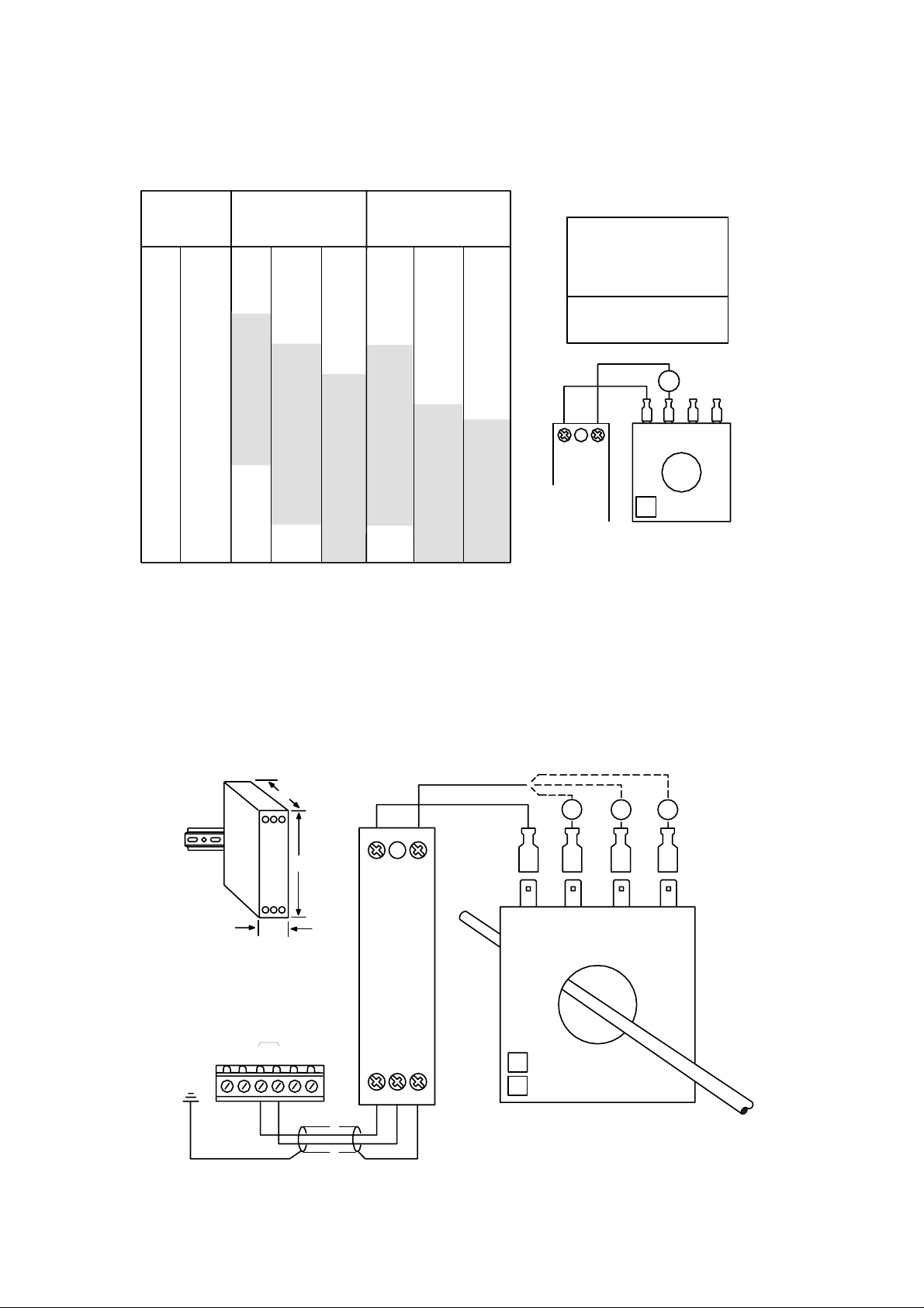
Installation
35mm
DIN Rail
Mount
VSD Box
X05
182217
+20Vdc
20mm
C
D
V
4
2
+
192120
75mm
80mm
l
a
n
ig
S
d
e
e
p
S
signal
231
Frequency
Detect
Module
564
A
12 3 4
Current
Sensor
1
25A/50A/100A
200A/400A/600A
2
B
C
Page 3

1) Ensure power to the compressor and driv e unit is switched off and securely isolated.
2) Mount the ‘Frequency Detect Module’ within the compressor starter or control panel area.
3) Mount the ‘Current Sensor’ on to one of the three phase power supply cables of the main
drive motor, it is not important which cable is selected. Ensure the current sensor is
secured and is not positioned near to, or is able to come into contact with, exposed high
voltage terminals.
4) Connect the Current Sensor to the Frequency Detect Module using single core 1.0mm³ to
1.5mm³ cable with a suitable insulation rating. Use the kit selection table to determine the
correct connections to the current sensor dependant on motor kW rating, operating voltage
and sensor positioning.
WARNING: VERY HIGH VOLTAGE POTENTIAL
Never apply power to the compressor motor with the current sensor terminals
unconnected. Always protect unused terminals with spare connectors or
insulation material.
The frequency detect module derives operating power from the CX or VSD connection; there
is no requirement to provide a separate power supply.
Harmonic and Drive Switching Frequency Interference
For variable frequency/speed (VSD, VFD) drives that are not fitted with motor side chocks
and/or electrical filtration devices the current sensor may be subject to harmonics and/or
switching frequencies. This can result in the sensor detecting and re porting frequencies much
higher than the fundamental drive frequency. For example; if the variable frequency drive is
providing 60Hz for maximum speed (100%) and 30Hz for minimum speed (50 % ) the reported
frequency may be 180Hz at 100%; three times the intended maximum fundamental
frequency. This value is typical of high harmonic frequencies being present on the motor
phase wires. In other instances the detected and reported frequency may be much high than
expected and the frequency reading erratic and non-consistent. This is typical of high drive
switching frequency interference being present on the motor phase wires.
To overcome this:
1) The sensor should be located as far away from the drive unit as possible; near as
possible to the motor.
2) Select the next higher current sensor rating/connection. For example, if the
rating/connection is 2A, use 2B instead; this will reduce the level of
harmonic/switching frequency pick-up. Note: If the current sensor rating/connection is
1C, then kit 2 will be required and rating/connection 2A used.
3) Fit ‘chocks’ to each of the drive unit motor phase outputs and locate the sensor
downstream of the phase ‘chock’ device.
4) Fit high interference frequency filter to the drive phase outputs and locate the sensor
downstream of the filter device.
 Loading...