

Ingersoll-Rand twe065e13fa1 Installation, Operation And Maintenance Manual
Installation, Operation,
and Maintenance
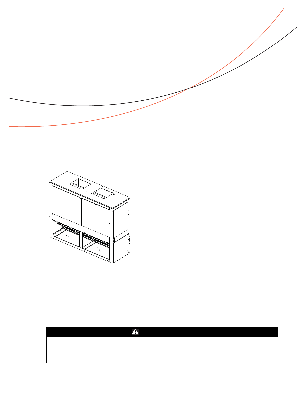
Split System Air Handlers
5-20 Tons
Model (60 Hz) Model (50 Hz)
TWE061D/E***A TWE051D***A
TWE090D/E***A TWE076D***A
TWE120D/E***A TWE101D/E***A
TWE150E***A TWE126E***A
TWE180E***A TWE156E***A
TWE240E***A TWE201E***A
Only qualified personnel should install and service the equipment. The installation, starting up, and
servicing of heating, ventilating, and air-conditioning equipment can be hazardous and requires specific
knowledge and training. Improperly installed, adjusted or altered equipment by an unqualified person could
result in death or serious injury. When working on the equipment, observe all precautions in the literature
and on the tags, stickers, and labels that are attached to the equipment.
January 2012 SSA-SVX06B-EN
SAFETY WARNING
Warnings, Cautions and Notices
Warnings, Cautions and Notices. Note that warnings, cautions and notices appear at
appropriate intervals throughout this manual. Warnings are provide to alert installing contractors
to potential hazards that could result in death or personal injury. Cautions are designed to alert
personnel to hazardous situations that could result in personal injury, while notices indicate a
situation that could result in equipment or property-damage-only accidents.
Your personal safety and the proper operation of this machine depend upon the strict observance
of these precautions.
Read this manual thoroughly before operating or servicing this unit.
ATTENTION: Warnings, Cautions and Notices appear at appropriate sections throughout this
literature. Read these carefully:
WARNING
CAUTIONs
NOTICE:
Indicates a potentially hazardous situation which, if not avoided, could result in
death or serious injury.
Indicates a potentially hazardous situation which, if not avoided, could result in
minor or moderate injury. It could also be used to alert against unsafe practices.
Indicates a situation that could result in equipment or property-damage only
accidents
Important
Environmental Concerns!
Scientific research has shown that certain man-made chemicals can affect the earth’s naturally
occurring stratospheric ozone layer when released to the atmosphere. In particular, several of the
identified chemicals that may affect the ozone layer are refrigerants that contain Chlorine, Fluorine
and Carbon (CFCs) and those containing Hydrogen, Chlorine, Fluorine and Carbon (HCFCs). Not all
refrigerants containing these compounds have the same potential impact to the environment.
Trane advocates the responsible handling of all refrigerants-including industry replacements for
CFCs such as HCFCs and HFCs.
Responsible Refrigerant Practices!
Trane believes that responsible refrigerant practices are important to the environment, our
customers, and the air conditioning industry. All technicians who handle refrigerants must be
certified. The Federal Clean Air Act (Section 608) sets forth the requirements for handling,
reclaiming, recovering and recycling of certain refrigerants and the equipment that is used in these
service procedures. In addition, some states or municipalities may have additional requirements
that must also be adhered to for responsible management of refrigerants. Know the applicable
laws and follow them.
Important: DO NOT release refrigerant to the atmosphere! If adding or removing refrigerant is
required, the service technician must comply with all federal, state, and local laws.
Important: One copy of this document ships inside the control panel of each unit and is
customer property. It must be retained by the unit’s maintenance personnel.
Proper Field Wiring and Grounding Required!
All field wiring MUST be performed by qualified personnel. Improperly installed and grounded
field wiring poses FIRE and ELECTROCUTION hazards. To avoid these hazards, you MUST
follow requirements for field wiring installation and grounding as described in NEC and your
local/state electrical codes. Failure to follow code could result in death or serious injury.
© 2012 Trane All rights reserved SSA-SVX06B-EN
WARNI NG
Warnings, Cautions and Notices
WARNI NG
Personal Protective Equipment (PPE) Required!
Installing/servicing this unit could result in exposure to electrical, mechanical and chemical
hazards.
• Before installing/servicing this unit, technicians MUST put on all Personal Protective
Equipment (PPE) recommended for the work being undertaken. ALWAYS refer to appropriate
MSDS sheets and OSHA guidelines for proper PPE.
• When working with or around hazardous chemicals, ALWAYS refer to the appropriate MSDS
sheets and OSHA guidelines for information on allowable personal exposure levels, proper
respiratory protection and handling recommendations.
• If there is a risk of arc or flash, technicians MUST put on all Personal Protective Equipment
(PPE) in accordance with NFPA 70E or other country-specific requirements for arc flash
protection, PRIOR to servicing the unit.
Failure to follow recommendations could result in death or serious injury.
WARNING
Refrigerant under High Pressure!
System contains oil and refrigerant under high pressure. Recover refrigerant to relieve pressure
before opening the system. See unit nameplate for refrigerant type. Do not use non-approved
refrigerants, refrigerant substitutes, or refrigerant additives. Failure to recover refrigerant to
relieve pressure or the use of non-approved refrigerants, refrigerant substitutes, or refrigerant
additives could result in an explosion which could result in death or serious injury or
equipment damage.
WARNING
R-410A Refrigerant under Higher Pressure than R-22!
The units described in this manual use R-410A refrigerant which operates at higher pressures
than R-22 refrigerant. Use ONLY R-410A rated service equipment or components with these
units. For specific handling concerns with R-410A, please contact your local Trane
representative.
Failure to use R-410A rated service equipment or components could result in equipment
exploding under R-410A high pressures which could result in death, serious injury, or
equipment damage.
This booklet describes proper installation, operation, and maintenance procedures for air cooled
systems. By carefully reviewing the information within this manual and following the instructions,
the risk of improper operation and/or component damage will be minimized. It is important that
periodic maintenance be performed to help assure trouble free operation. Should equipment
failure occur, contact a qualified service organization with qualified, experienced HVAC technicians
to properly diagnose and repair this equipment.
Important: All phases of this installation must comply with the NATIONAL, STATE & LOCAL
CODES. In addition to local codes, the installation must conform with National
Electric Code -ANSI/NFPA NO. 70 LATEST REVISION.
Any individual installing, maintaining, or servicing this equipment must be properly trained,
licensed and qualified.
Important: Do not remove the VFD without first contacting technical support! For performance
-related questions and diagnostic support in North America call 1-877-872-6363. Any
return requires a claim number FIRST. Removal of the VFD prior to this step will void
the unit’s warranties.
SSA-SVX06B-EN 3

Table of Contents
Model Number Description . . . . . . . . . . . . . . . . . . . . . . . . . . . . . . . . . . . . . . . . . . . . . . 6
General Information . . . . . . . . . . . . . . . . . . . . . . . . . . . . . . . . . . . . . . . . . . . . . . . . . . . . 7
Pre-Installation . . . . . . . . . . . . . . . . . . . . . . . . . . . . . . . . . . . . . . . . . . . . . . . . . . . . . . . . . 9
Dimensional Data . . . . . . . . . . . . . . . . . . . . . . . . . . . . . . . . . . . . . . . . . . . . . . . . . . . . . . 14
Electrical Data - Standard, SZVAV and 2-Speed VFD . . . . . . . . . . . . . . . . . . . . . . 23
Installation . . . . . . . . . . . . . . . . . . . . . . . . . . . . . . . . . . . . . . . . . . . . . . . . . . . . . . . . . . . . 35
Electrical Wiring . . . . . . . . . . . . . . . . . . . . . . . . . . . . . . . . . . . . . . . . . . . . . . . . . . 44
Installation Checklist . . . . . . . . . . . . . . . . . . . . . . . . . . . . . . . . . . . . . . . . . . . 7
Unit Inspection . . . . . . . . . . . . . . . . . . . . . . . . . . . . . . . . . . . . . . . . . . . . . . . 7
Initial Leak Test . . . . . . . . . . . . . . . . . . . . . . . . . . . . . . . . . . . . . . . . . . . . . . . 7
Lifting Recommendations . . . . . . . . . . . . . . . . . . . . . . . . . . . . . . . . . . . . . . . 7
Repositioning Drain Pan . . . . . . . . . . . . . . . . . . . . . . . . . . . . . . . . . . . . . . . . 9
Field Conversion to 460 Volt . . . . . . . . . . . . . . . . . . . . . . . . . . . . . . . . . . . . 11
Refrigerant Piping . . . . . . . . . . . . . . . . . . . . . . . . . . . . . . . . . . . . . . . . . . . . 12
Installations, Limitations and Recommendations . . . . . . . . . . . . . . . . . . 13
Horizontal Suspension . . . . . . . . . . . . . . . . . . . . . . . . . . . . . . . . . . . . . . . . 35
Refrigerant Piping . . . . . . . . . . . . . . . . . . . . . . . . . . . . . . . . . . . . . . . . . . . . 36
Condensate Piping . . . . . . . . . . . . . . . . . . . . . . . . . . . . . . . . . . . . . . . . . . . 37
Filters . . . . . . . . . . . . . . . . . . . . . . . . . . . . . . . . . . . . . . . . . . . . . . . . . . . . . . 37
Duct Connections . . . . . . . . . . . . . . . . . . . . . . . . . . . . . . . . . . . . . . . . . . . . 37
Air Flow Settings . . . . . . . . . . . . . . . . . . . . . . . . . . . . . . . . . . . . . . . . . . . . . 37
Electrical Connections . . . . . . . . . . . . . . . . . . . . . . . . . . . . . . . . . . . . . . . . . 40
Setpoints . . . . . . . . . . . . . . . . . . . . . . . . . . . . . . . . . . . . . . . . . . . . . . . . . . . 42
Checkout Procedure . . . . . . . . . . . . . . . . . . . . . . . . . . . . . . . . . . . . . . . . . . 44
Installation Checklist . . . . . . . . . . . . . . . . . . . . . . . . . . . . . . . . . . . . . . . . . . 44
Thermostat and Control Connections for Electromechanical Controls . 45
Thermostat and Control Connections for ReliaTel™ Controls . . . . . . . . 46
Start-Up . . . . . . . . . . . . . . . . . . . . . . . . . . . . . . . . . . . . . . . . . . . . . . . . . . . . . . . . . . . . . . 48
Sequence of Operation . . . . . . . . . . . . . . . . . . . . . . . . . . . . . . . . . . . . . . . . . . . . 48
Maintenance . . . . . . . . . . . . . . . . . . . . . . . . . . . . . . . . . . . . . . . . . . . . . . . . . . . . . . . . . . 51
Warranty . . . . . . . . . . . . . . . . . . . . . . . . . . . . . . . . . . . . . . . . . . . . . . . . . . . . . . . . . . . . . 56
4 SSA-SVX06B-EN
Variable Air Volume Applications (SZVAV) . . . . . . . . . . . . . . . . . . . . . . . . 48
2 Speed VFD Applications . . . . . . . . . . . . . . . . . . . . . . . . . . . . . . . . . . . . . 50
Fan Belt Adjustment . . . . . . . . . . . . . . . . . . . . . . . . . . . . . . . . . . . . . . . . . . 51
Monthly . . . . . . . . . . . . . . . . . . . . . . . . . . . . . . . . . . . . . . . . . . . . . . . . . . . . 52
Annually (Cooling Season) . . . . . . . . . . . . . . . . . . . . . . . . . . . . . . . . . . . . . 53
Coil Cleaning . . . . . . . . . . . . . . . . . . . . . . . . . . . . . . . . . . . . . . . . . . . . . . . . 53
Precautionary Measures . . . . . . . . . . . . . . . . . . . . . . . . . . . . . . . . . . . . . . . 54
First Aid Measures . . . . . . . . . . . . . . . . . . . . . . . . . . . . . . . . . . . . . . . . . . . 54
Maintenance Log . . . . . . . . . . . . . . . . . . . . . . . . . . . . . . . . . . . . . . . . . . . . . 55

Central Air Conditioner . . . . . . . . . . . . . . . . . . . . . . . . . . . . . . . . . . . . . . . . . . . . 56
Commercial Equipment Rated 20 Tons and Larger and Related Accessories
(Parts Only)
. . . . . . . . . . . . . . . . . . . . . . . . . . . . . . . . . . . . . . . . . . . . . . . . . . . . . . 56
Wiring Diagram Matrix . . . . . . . . . . . . . . . . . . . . . . . . . . . . . . . . . . . . . . . . . . . . . . . . . 58
SSA-SVX06B-EN 5

Model Number Description
T W E 2 4 0 E 3 0 0 ** *
1 2 3 4 5 6 7 8 9 10 11 12
Model Number Description
All products are identified by a multiple-character model number that precisely identifies a particular type of
unit. An explanation of the alphanumeric identification code is provided. Its use will enable the owner/
operator, installing contractors, and service engineers to define the operation, specific components, and
other options for any specific unit.
Note: When ordering replacement parts or requesting service, be sure to refer to the specific model number,
serial number, and DL number (if applicable) stamped on the unit nameplate.
DIGITS 1 - 3: Product Type
TWE = Split System Heat Pump/Cooling Air Handler
DIGITS 4 - 6: Nominal Gross Cooling Capacity (MBh)
061 = 5 Tons (60 Hz) 051 = 4.6 Tons (50 Hz)
090 = 7½ Tons (60 Hz) 076 = 6.25 Tons (50 Hz)
120 = 10 Tons (60 Hz) 101 = 8.33 Tons (50 Hz)
150 = 12½ Tons (60 Hz) 126 = 10.4 Tons (50 Hz)
180 = 15 Tons (60 Hz) 156 = 13 Tons (50 Hz)
240 = 20 Tons (60 Hz) 201 = 16.7 Tons (50 Hz)
DIGIT 7: Major Development Sequence
D = Single Circuit
E = Dual Circuit
DIGIT 8: Electrical Characteristics
1 = 208-230/60/1 W = 575/60/3
3 = 208-230/60/3 D = 380-415/50/3
4 = 460/60/3 K = 380/60/3
DIGITS 9 - 10: Factory Installed Options
00 = Packed Stock (Standard)
03 = 2-speed Variable Frequency Drive (VFD) Standard Motor Electromechanical Condenser only
04 = 2-speed Variable Frequency Drive (VFD) Oversized Motor Electromechanical Condenser only
R3 = Single Zone Variable Air Volume (VFD) Standard Motor - Reliatel Cond only
R4 = Single Zone Variable Air Volume (VFD) Oversized Motor - Reliatel Cond only
DIGITS 11: Minor Design Sequence
* = Current Design Sequence
1
DIGITS 12: Service Digit
* = Current Design Sequence1
1
* = sequential alpha character
6 SSA-SVX06B-EN
General Information
Installation procedures should be performed in the sequence that they appear in this manual. Do
not destroy or remove the manual from the unit. The manual should remain weather-protected with
the unit until all installation procedures are complete.
Note: It is not the intention of this manual to cover all possible variations in systems that may
occur or to provide comprehensive information concerning every possible contingency that
may be encountered during an installation. If additional information is required or if specific
problems arise that are not fully discussed in this manual, contact your local sales office.
This manual covers installation of the TWE air handlers. These air handler models incorporate a
single slab coil assembly, improved application flexibility, servicing, maintenance accessibility and
an improved accessory line. They are fully convertible, (vertical to horizontal discharge) without
field removal of the coil assembly. They are shipped ready for horizontal installation.
All units have one drain pan that can be installed in any one of four positions. This allows for vertical
or horizontal applications and right or left exit.
Important: All dual circuit (digit 7 = E) have an intertwined coil
Installation Checklist
An “Installation Checklist” is provided at the end of the installation section of this manual. Use the
checklist to verify that all necessary installation procedures have been completed. Do not use the
checklist as a substitute for reading the information contained in the manual. Read the entire
manual before beginning installation procedures.
Unit Inspection
Inspect material carefully for any shipping damage. If damaged, it must be reported to, and claims
made against the transportation company. Compare the information that appears on the unit
nameplate with ordering and submittal data to ensure the proper unit was shipped. Available
power supply must be compatible with electrical characteristics specified on component
nameplates. Replace damaged parts with authorized parts only.
Initial Leak Test
All TWE units are shipped with a holding charge of nitrogen in each circuit. Remove the access
panel shown in Figure 12, p. 21. Locate the liquid line or suction line access valve for each circuit.
Install gauges to determine if the circuits are still pressurized. If not, the charge has escaped. Repair
as required to obtain a leak-free circuit.
Lifting Recommendations
WARNING
Improper Unit Lift!
Each of the cables (chains or slings) used to lift the unit must be capable of supporting the
entire weight of the unit. Lifting cables (chains or slings) may not be of the same length. Adjust
as necessary for even unit lift. Other lifting arrangements may cause equipment or propertyonly damage. Test lift unit approximately 24 inches to verify proper center of gravity lift point.
To avoid dropping of unit, reposition lifting point if unit is not level.
Failure to properly lift unit could result in unit dropping and possibly crushing operator/
technician which could result in death or serious injury and possible equipment or propertyonly damage. Refer to Ta b l e 1 and Ta b l e 2 for unit weight.
SSA-SVX06B-EN 7
General Information
NOTICE:
Equipment Damage!
Use spreader bars to prevent straps from damaging the unit. Install the bars between lifting
straps, both underneath the unit and above the unit. This will prevent the straps from crushing
the unit cabinet or damaging the unit finish.
Before preparing the unit for lifting, estimate the approximate center of gravity for lifting safety.
Because of placement of internal components, the unit weight may be unevenly distributed.
Approximate unit weights are given in Ta b le 1 and Ta b l e 2, p. 8.
The crated unit can be moved using a forklift of suitable capacity. For lifting the unit into an elevated
mounting position, run lifting straps or slings under the unit and attach securely to the lifting device.
Table 1. TWE Unit and Corner Weights - lbs (60 Hz)
Corner Weights - Vertical Corner Weights - Horizontal
Tons Model No. Shipping Max (lbs) Net Max (lbs)
5 TWE061D/E 263 232 55 71 51 55 54 67 50 61
7½ TWE090D/E 360 323 67 99 75 82 56 92 87 88
10 TWE120D/E 429 393 77 121 110 85 79 118 77 119
12½ TWE150E 730 676 168 192 181 135 196 164 145 171
15 TWE180E 729 675 167 192 181 135 196 163 145 171
20 TWE240E 891 818 258 168 161 231 256 181 146 235
1234ABCD
Table 2. TWE Unit and Corner Weights - kg (50 Hz)
Corner Weights - Vertical Corner Weights - Horizontal
Tons Model No. Shipping Max (kg) Net Max (kg)
5 TWE051D/E 118 104 25 32 23 25 24 30 23 27
7½ TWE076D/E 162 145 30 45 34 37 25 41 39 40
10 TWE101D/E 193 177 35 54 50 38 36 53 35 54
12½ TWE126E 329 304 76 86 81 61 88 74 65 77
15 TWE156E 328 304 75 86 81 61 88 73 65 77
20 TWE201E 401 368 116 76 72 104 115 81 66 106
1234ABCD
8 SSA-SVX06B-EN
Pre-Installation
The final position for the air handler must be dictated by required service access to it, weight
distribution over structural supports, and by the locations of electrical, refrigerant and condensate
drainage connections. After this is determined, the following preparations should be made.
Repositioning Drain Pan
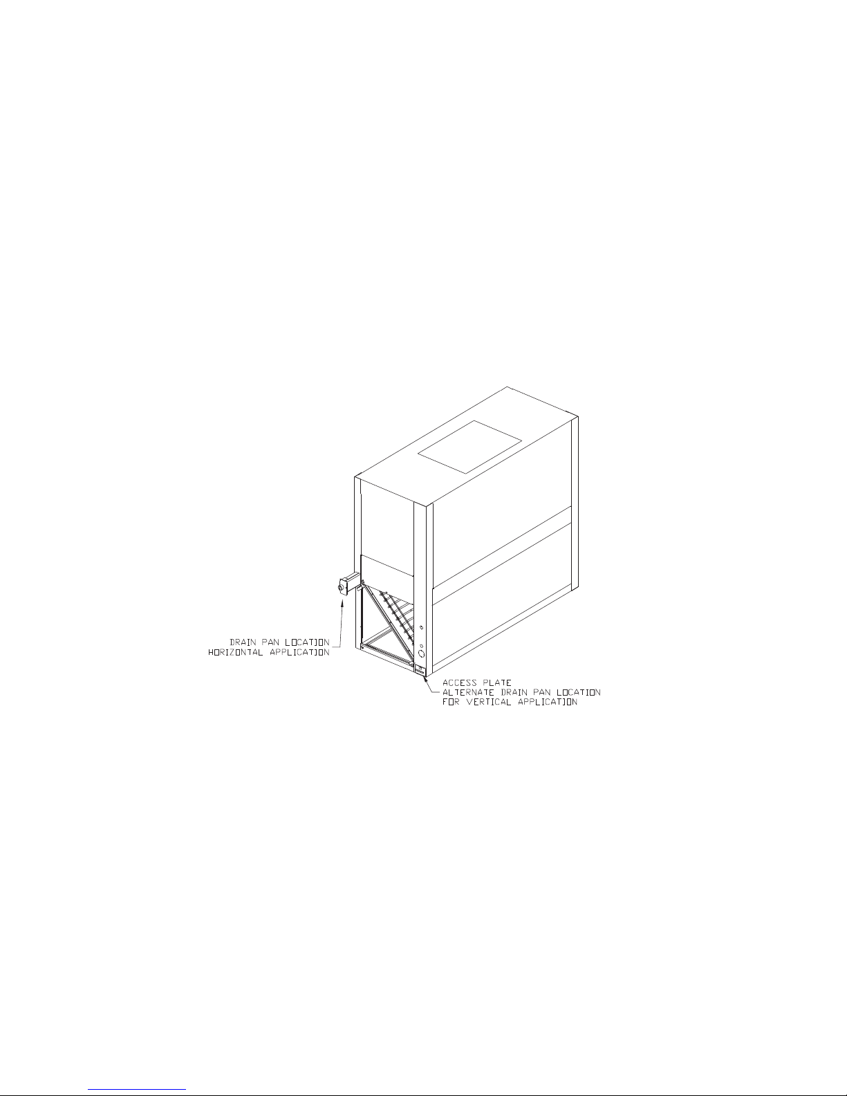
These air handlers come with one drain pan that can be installed in any one of four positions; this
allows for vertical or horizontal application and right or left condensate line connection. The drain
pan can also be easily removed for periodic cleaning.
Note: Important! All air handlers are shipped with the drain pan installed in the horizontal position
and the connection on the left side (as shown in Figure 1. If an alternate position is required,
the drain pan should be repositioned before setting the air handler.
Figure 1. Drain Pan Location
SSA-SVX06B-EN 9
Pre-Installation
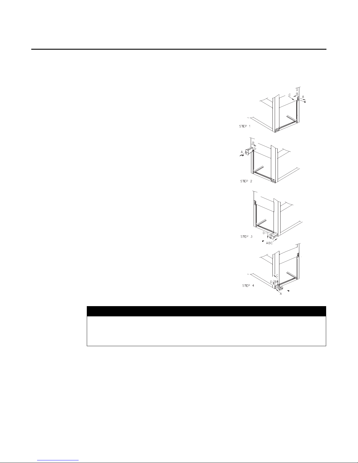
Process for Drain Pan Relocation
1. Remove the access plate at the opposite end of the drain
connection. This plate secures and lifts the back end of
the drain pan for sloping. It must be removed before the
drain pan can be removed. This is done as follows:
a. Remove the screw
b. Lift the access plate up
c. Pull the plate out. If the drain pan is to be moved to
the vertical position also remove the other two
access plates.
2. Remove the screw securing the drain pan.
a. Lift the pan up
b. Slide the pan out
3. Install the drain pan into the new position.
a. Slide the drain pan into the opening
b. Lift the drain pan up
c. Push it in all the way
d. Drop it down over the lip of the opening, secure with
screw
4. Install the access plate on the opposite end of the drain
pain.
a. Slide the edge of the access plate under the drain pan
b. Lift the access plate and drain pan up
c. Push the access plate in
d. Drop the access plate down over the lip of the
opening, secure with screw. If the drain pan is being
moved to the vertical position, install the other
access plates over the horizontal position opening.
Figure 2. Drain Pan Relocation
System Component Damage!
These air handlers are shipped with a dry nitrogen holding charge in the coil. Depress or
remove the access valve core to bleed off the nitrogen prior to brazing. Temporarily cap off
tubes if the refrigerant line connections are to be made later.
10 SSA-SVX06B-EN
NOTICE:

Field Conversion to 460 Volt
Hazardous Voltage w/Capacitors!
Disconnect all electric power, including remote disconnects and discharge all motor start/run
capacitors before servicing. Follow proper lockout/tagout procedures to ensure the power
cannot be inadvertently energized. For variable frequency drives or other energy storing
components provided by Trane or others, refer to the appropriate manufacturer’s literature for
allowable waiting periods for discharge of capacitors. Verify with an appropriate voltmeter that
all capacitors have discharged. Failure to disconnect power and discharge capacitors before
servicing could result in death or serious injury.
For additional information regarding the safe discharge of capacitors, see PROD-SVB06A-EN
Proper Field Wiring and Grounding Required!
All field wiring MUST be performed by qualified personnel. Improperly installed and grounded
field wiring poses FIRE and ELECTROCUTION hazards. To avoid these hazards, you MUST
follow requirements for field wiring installation and grounding as described in NEC and your
local/state electrical codes. Failure to follow code could result in death or serious injury.
Pre-Installation
WARNING
WARNING
• Available power supply must agree with electrical data on component nameplate.
• Some standard air handlers are shipped wired for 208-230 volt applications and can be
converted for 460 volt by rewiring the blower motor, see Figure 3. (This includes models
TWE090D3, TWE090E3, TWE120D3, TWE120E3, TWE150E3 and TWE180E3).
Converting Motor to 460 Volt
1. Ensure power is disconnected to unit by
following the warning above.
2. Remove unit access panels closest to
motor.
3. Open terminal cover on lead end of
motor.
4. Pull voltage selector plug from low
voltage selection (see Figure 3).
5. Shift the plug (or rotate 180°) to align
plug for high voltage selection and reinsert plug.
Important: When re-inserting voltage
selection plug, ensure it is
fully seated.
6. Replace terminal cover on lead end of
motor.
7. Replace unit access panels.
Figure 3. Voltage Change Plug
SSA-SVX06B-EN 11
Pre-Installation
Top bracket screws
Rotate 4°
clockwise
Refrigerant Piping
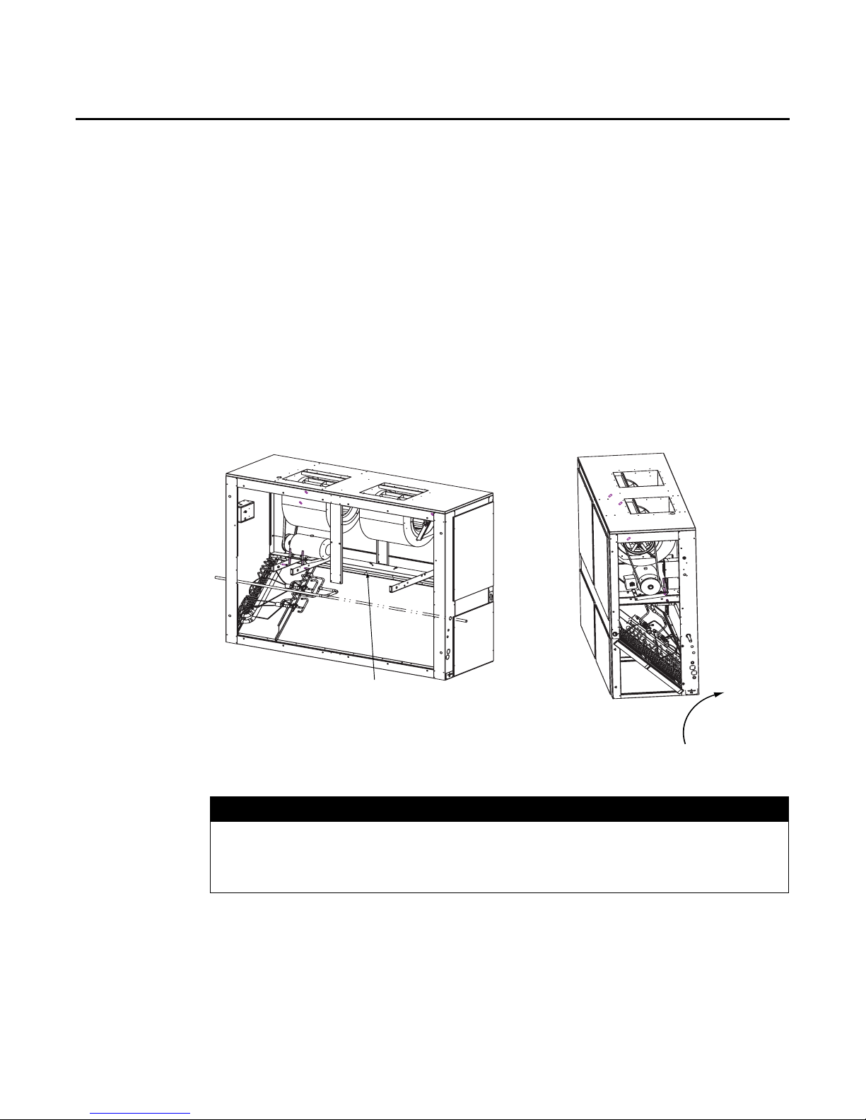
Evaporator Coil Orientation
Important: Applies only to TWE126/150 and 156/180 when positioned for vertical upflow. Unit
Process for reorienting evaporator coil on TWE126, 150, 156 and 180 only.
1. Remove screws from top evaporator coil bracket (bracket that attaches coil to cabinet and runs
2. Rotate evaporator coil approximately 4 degrees clockwise - looking from the control box end
3. Reinsert screws in evaporator coil bracket.
Figure 4. Evaporator Coil Reorientation for TWE126, 150, 156, 180
is shipped in the horizontal position. If installing in the vertical position, the coil
must be reoriented by rotating the coil 4 degrees (control box side) from the
shipped position. See instructions and Figure 4 below.
the length of the unit).
(see Figure 4). When the evaporator coil is rotated, the lower set of evaporator coil bracket holes
will align with the support bracket (from which it was originally fastened).
Preparation
Equipment Damage!
Do not apply heat to remove seal caps until the gauge port cores have been removed. If seal
caps are intact, application of heat may generate excessive pressure in the unit and result in
damage to the coil or expansion valve.
The air handler is designed so that refrigerant piping can enter from either the right or left hand
side. It is shipped with the intent that the refrigerant lines will enter from the left hand side. To
convert to right hand entry, unbraze the elbow on the suction line and rotate 180° and rebraze.
Important: Access to refrigerant lines is limited in all horizontal and some vertical applications.
12 SSA-SVX06B-EN
NOTICE:
Therefore, refrigerant lines should be stubbed out and temporarily capped prior to
setting the air handler. Protect adjacent surfaces from heat damage when brazing in
and around the air handler.
Installations, Limitations and Recommendations
System Component Damage!
Properly insulate all refrigerant gas piping to prevent possible water damage due to
condensation and to prevent capacity loss and possible compressor damage.
The general location of the air handler is normally selected by the architect, contractor and/or
buyer. For proper installation the following items must be considered.
• Available power supply must agree with electrical data on component nameplate.
• If external accessories are installed on the unit, additional clearances must be provided.
• All duct work should be properly insulated to prevent condensation and heat loss.
• Refrigerant gas piping must be insulated.
It is recommended that the outline drawings (Figure 6, p. 15 - Figure 13, p. 22) be studied and
dimensions properly noted and checked against the selected installation site. By noting in advance
which features are to be used, proper clearance allowances can be made for installation and
possible future service.
Important: When installing these units “free standing” with discharge grills and isolators, a top
support with isolator should be added to prevent tipping. Support and isolator can
be attached to a wall or other appropriate structure.
Important: If adding external accessories to the unit, additional clearances must be considered
for the overall space needed.
For installation of accessories available for this air handler, follow the instructions packed with each
accessory.
Pre-Installation
NOTICE:
SSA-SVX06B-EN 13
Dimensional Data
H
D
W
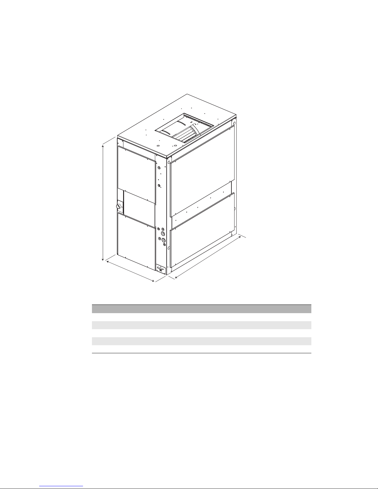
Figure 5. TWE Quick Reference
Note: Full dimensional data available on next pages.
H - in. (mm) W - in. (mm) D - in. (mm)
TWE051, 061 48-1/8” (1222.4) 39-5/8” (1006.5) 23-5/8” (600)
TWE076, 090 54-1/8” (1374.8) 49-1/8” (1247.8) 26-1/2” (673.1)
TWE101, 120 54-1/8” (1374.8) 65-1/8” (1654.2) 26-1/2” (673.1)
TWE126, 150, 156, 180 69-1/8” (1756) 81-1/4” (2063.7) 30 (762)
TWE201, 240 71-7/8” (1806.6) 94-1/4” (2394) 32-1/8” (816)
14 SSA-SVX06B-EN

3" (76.2)
48 1/16"
(1220.8)
10 7/16"
(265.1)
34 9/16"
(877.9)
35 5/8"
(904.9)
1 1/8"
(28.6)
12"
(304.8)
13 9/16" (344.5)
20 1/16"
(509.6)
1 11/16"
(42.9)
5 15/16"
(150.8)
13 3/16" (335)
12"
(304.8)
13 9/16"
(344.5)
13 5/16"
(338.14)
1 3/4"
(44.45)
2 3/4"
(69.9)
DRAIN CONNECTION
FOR HORIZONTAL
(SEE NOTE 2,3, 5 )
32 1/2"
(825.5)
12 7/16"
(315.9)
1 3/8"
(34.9)
.99" (25.15)
.99" (25.15)
1 3/8" (34.9)
3 3/16" (81)
3 7/16" (87.3)
22 5/8"
(574.7)
22 5/8"
(574.7)
16 1/4"
(412.8)
.77"
(19.6)
.50" (12.7)
3 9/16"
(90.5)
7 9/16"
(192.1)
37 15/16"
(963.6)
24 1/16"
(611.2)
2 5/16"
(58.7)
6 7/8"
(174.6)
6 15/16" (176.2)
BOTTOM RETURN
SIDE RETURN
CONTROL BOX
ACCESS PANEL
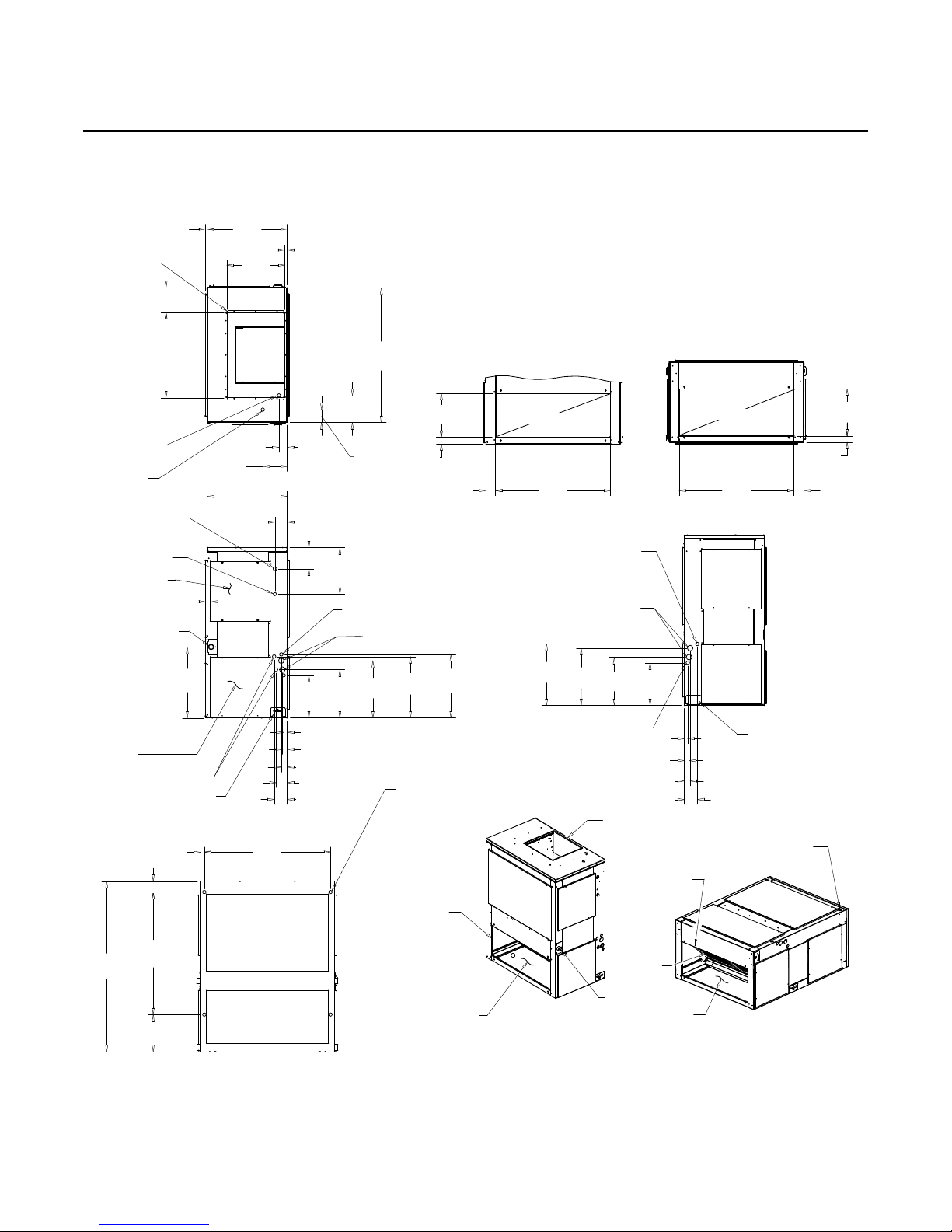
NOTES:
1. PANEL DEPTH 1/2" (12.7) (TYP. ALL PANELS).
2. REMOVABLE DRAIN PAN AND ATTACHED DRAIN CONNECTION MAY BE INSTALLED ON END
OF UNIT IN EITHER THE VERTICAL OR HORIZONTAL CONFIGURATION, PLASTIC DRAIN PAN
ACCESS PLATE ON THE END OF UNIT OPPOSITE DRAIN CONNECTION MUST BE REMOVED TO
SLIDE DRAIN PAN OUT OF UNIT FOR CLEANING. ACCESS PLATE MUST BE RE-INSTALLED AFTER
SLIDING DRAIN PAN BACK INTO UNIT.
3. IF PERIODIC DRAIN PAN CLEANING IS REQUIRED, ALLOW ROOM FOR PARTIAL REMOVAL OF
DRAIN PAN CONNECTION AT END OF UNIT.
4. 1" (25.4) FEMALE SCHED. 40 (10.2) PVC PIPE DRAIN CONNECTION VERTICAL CONFIGURATION.
5. 1" (25.4) FEMALE SCHED. 40 (10.2) PVC PIPE DRAIN CONNECTION HORIZONTAL CONFIGURATION.
DIMENSIONAL DRAWING
4.6 - 6.25 TON AIR HANDLER
(SINGLE CIRCUIT)
SEE NOTES 2,3,4
SEE NOTES 2,3,4
(4) - HOLE FOR HORIZONTAL
SUSPENSION
COPPER LIQUID LINE
FIELD CONNECTION
COPPER SUCTION LINE
FIELD CONNECTION
LIQUID LINES
1 3/8" (34.9) O.D. SUCTION LINE
REMOTE BULB TXV
FILTER ACCESS PANEL
22" (558.8) MIN. DISTANCE
BOTH SIDE
FILTER
SUPPLY OPENING
BOTTOM RETURN
SIDE RETURN
BOTTOM RETURN
SUPPLY VERTICAL RETURN HORIZONTAL /
RETURN VERTICAL
SUPPLY HORIZONTAL RETURN VERTICAL /
RETURN HORIZONTA L
(4) - HOLE FOR HORIZONTAL
SUSPENSION
SIDE RETURN
CONTROL WIRING
LINE VOLTAGE
DUCT FLANGE
1" (25.4)
HEIGHT
SUPPLY
OPEN
HEATER
VENTILATION
HEATER CONTROL
AND SINGLE POWER
ENTRY WIRES
32 1/2"
(825.5)
2 3/4"
(69.9)
Figure 6. TWE051, 061 Air Handler, Single Circuit — in (mm)
Dimensional Data
SSA-SVX06B-EN 15
Dimensional Data
3" (76.2)
48 1/16"
(1220.8)
10 7/16"
(265.1)
34 9/16"
(877.9)
35 5/8"
(904.9)
1 1/8"
(28.6)
12"
(304.8)
13 9/16"
(344.5)
20 1/16"
(509.6)
1 11/16"
(42.9)
5 15/16"
(150.8)
13 3/16" (335)
16 1/8"
(409.6)
17 5/16"
(439.7)
17 7/8"
(454)
12"
(304.8)
13 9/16"
(344.5)
16 1/8"
(409.6)
17 5/16"
(439.7)
13 5/16"
(338.14)
1 3/4"
(44.45)
2 3/4"
(69.8)
32 1/2"
(825.5)
DRAIN CONNECTION
FOR HORIZONTAL
(SEE NOTE 2,3,5)
12 7/16"
(315.9)
3 11/16" (93.7)
1 11/16" (42.9)
1 3/8" (34.9)
.99" (25.15)
.99" (25.15)
1 3/8" (34.9)
1 11/16" (42.9)
3 3/16" (81)
3 11/16" (93.7)
3 7/16" (87.3)
22 5/8"
(574.7)
1 13/16"
(46.04)
22 5/8"
(574.7)
16 1/4"
(412.8)
.77" (19.6)
.50" (12.7)
3 9/16"
(90.5)
7 9/16"
(192.1)
37 15/16"
(963.6)
24 1/16"
(611.2)
2 5/16"
(58.7)
6 7/8"
(174.6)
6 15/16"
(176.2)
BOTTOM RETURN
SIDE RETURN
DUCT FLANGE
1" (25.4) HEIGHT
SUPPLY
OPEN
CONTROL WIRING
LINE VOLTAGE
CONTROL BOX
ACCESS PANEL
NOTES:
1. PANEL DEPTH 1/2" (12.7) (TYP. ALL PANELS).
2. REMOVABLE DRAIN PAN AND ATTACHED DRAIN CONNECTION MAY BE INSTALLED ON END
OF UNIT IN EITHER THE VERTICAL OR HORIZONTAL CONFIGURATION, PLASTIC DRAIN PAN
ACCESS PLATE ON THE END OF UNIT OPPOSITE DRAIN CONNECTION MUST BE REMOVED TO
SLIDE DRAIN PAN OUT OF UNIT FOR CLEANING. ACCESS PLATE MUST BE RE-INSTALLED AFTER
SLIDING DRAIN PAN BACK INTO UNIT.
3. IF PERIODIC DRAIN PAN CLEANING IS REQUIRED, ALLOW ROOM FOR PARTIAL REMOVAL OF
DRAIN CONNECTION AT END OF UNIT.
4. 1" (25.4) FEMALE SCHED. 40 (10.2) PVC PIPE DRAIN CONNECTION VE
RTICAL CONFIGURATION.
5. 1" (25.4) FEMALE SCHED. 40 (10.2) PVC PIPE DRAIN CONNECTION HORIZONTAL CONFIGURATION.
DIMENSIONAL DRAWING
5 TON AIR HANDLER
(DUAL CIRCUIT)
SEE NOTES 2,3,4
SEE NOTES 2,3,4
SUPPLY VERTICAL RETURN HORIZONTAL /
RETURN VERTICAL
SUPPLY HORIZONTAL RETURN VERTICAL /
RETURN HORIZONTAL
(4) - HOLE FOR HORIZONTAL
SUSPENSION
COPPER LIQUID LINE
FIELD CONNECTION
COPPER SUCTION LINE
FIELD CONNECTION
LIQUID LINES
(2) REMOTE BULB TXV
FILTER ACCESS PANEL
22" (558.8) MIN. DISTANCE
BOTH SIDE
SIDE RETURN
SIDE RETURN
BOTTOM RETURN
BOTTOM RETURN
SUPPLY OPENING
FILTER
(4) HOLE FOR
HORIZONTAL
SUSPENSION
DRAIN CONNECTION
SUCTION LINE
COPPER LIQUID LINE
FIELD CONNECTION
HEATER
VENTILATION
HEATER CONTROL
AND SINGLE POWER
ENTRY WIRES
32 1/2"
(825.5)
2 3/4"
(69.8)
Figure 7. TWE061 Air Handler, Dual Circuit — in (mm)
16 SSA-SVX06B-EN
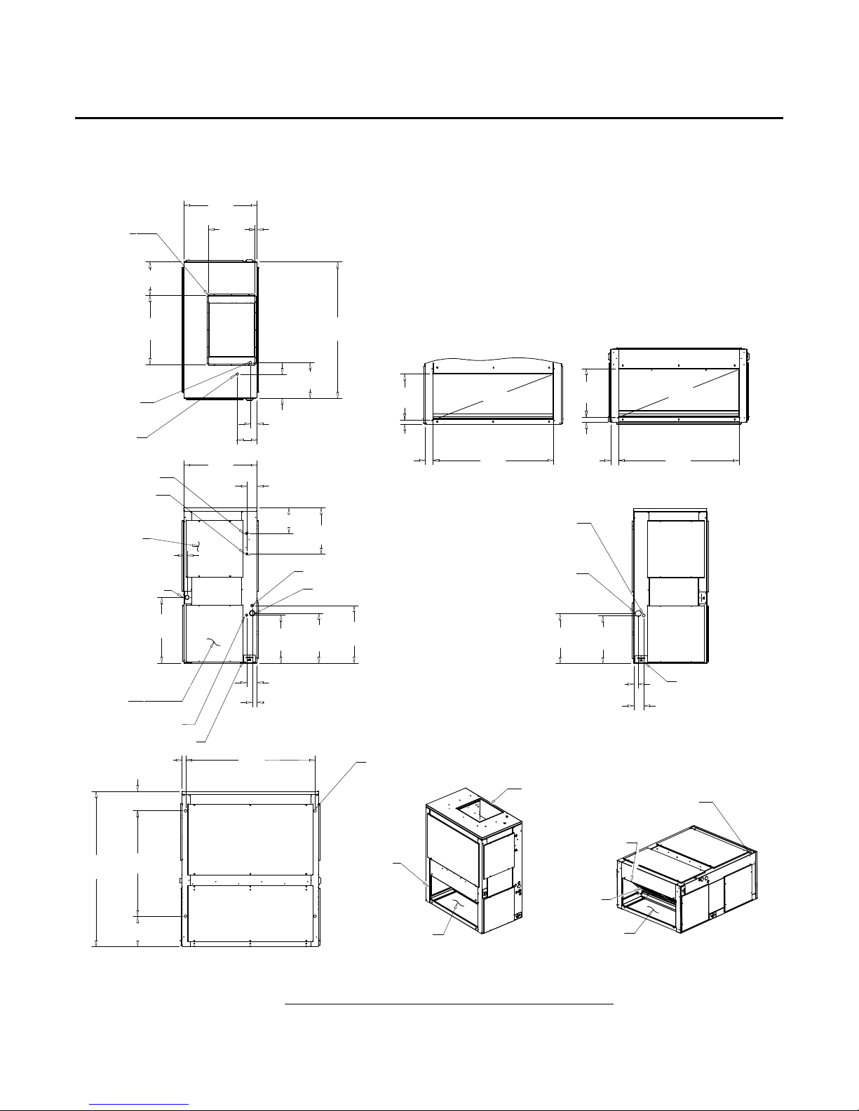
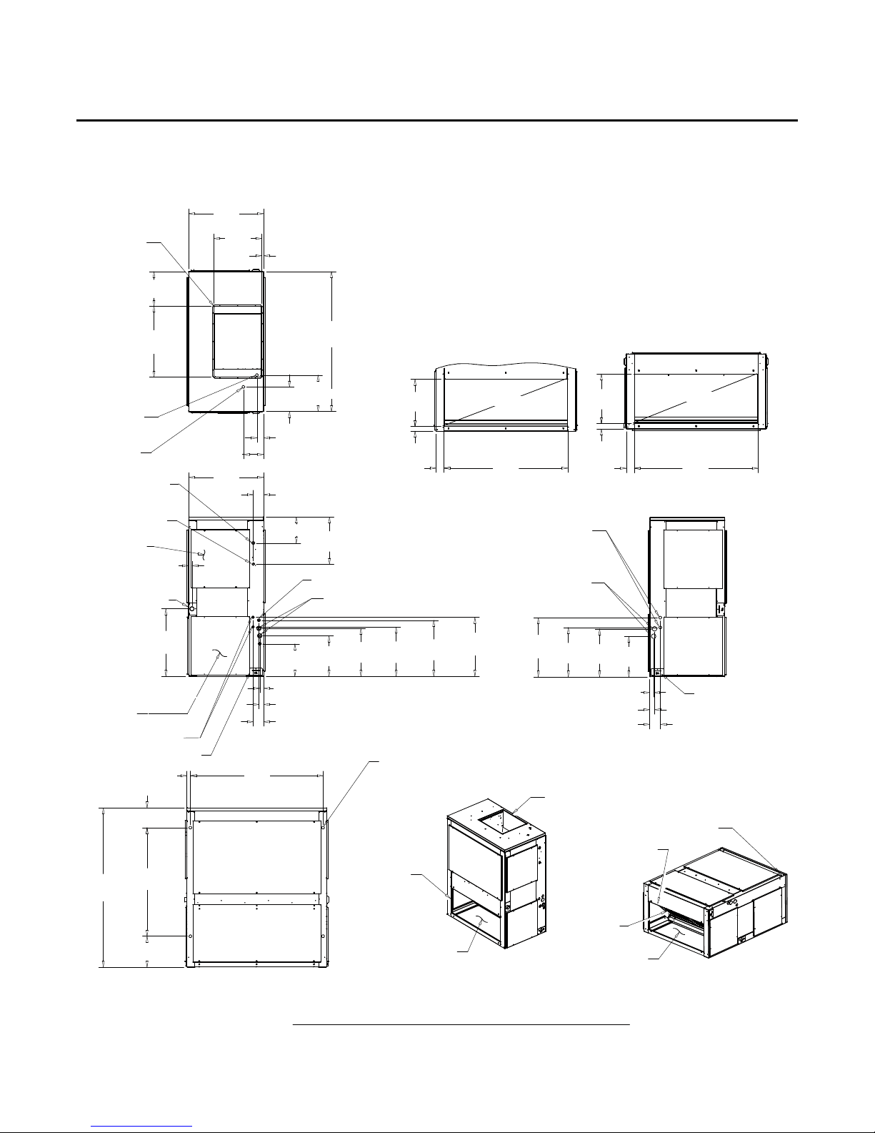
Figure 8. TWE076, 090 Air Handler, Single Circuit — in (mm)
NOTES:
1. PANEL DEPTH 1/2" (12.7) (TYP. ALL PANELS).
2. REMOVABLE DRAIN PAN AND ATTACHED DRAIN CONNECTION MAY BE INSTALLED ON END
OF UNIT IN EITHER THE VERTICAL OR HORIZONTAL CONFIGURATION, PLASTIC DRAIN PAN
ACCESS PLATE ON THE END OF UNIT OPPOSITE DRAIN CONNECTION MUST BE REMOVED TO
SLIDE DRAIN PAN OUT OF UNIT FOR CLEANING. ACCESS PLATE MUST BE RE-INSTALLED AFTER
SLIDING DRAIN PAN BACK INTO UNIT.
3. IF PERIODIC DRAIN PAN CLEANING IS REQUIRED, ALLOW ROOM FOR PARTIAL REMOVAL OF
DRAIN PAN CONNECTION AT END OF UNIT.
4. 1" (25.4) FEMALE SCHED. 40 (10.2) PVC PIPE DRAIN CONNECTION VE
5. 1" (25.4) FEMALE SCHED. 40 (10.2) PVC PIPE DRAIN CONNECTION HORIZONTAL CONFIGURATION.
47 1/2"
(1206.5)
16 1/16"
(408)
1 9/16"
(39.7)
2 3/4"
(69.85)
DUCT FLANGE
1" (25.4)
HEIGHT
11 11/16"
(296.8)
24 1/16"
(611.2)
HEATER CONTROL
AND SINGLE POWER
ENTRY WIRES
HEATER
VENTILATION
CONTROL WIRING
LINE VOLTAGE
CONTROL BOX
ACCESS PANEL
DRAIN CONNECTION
1 3/16" (30.2)
FOR HORIZONTAL
(SEE NOTE 2,3,5)
25 1/2"
(647.7)
16 1/4"
(412.8)
SUPPLY
OPEN
6 13/16"
(173)
25 1/2"
(647.7)
.70"
(17.8)
12 5/16"
8 5/16"
(312.7)
(211.1)
2 1/4" (57.15)
3 1/2" (88.9)
8 13/16" (223.8)
16"
(406.4)
REMOTE BULB TXV
SUCTION LINE
SIDE RETURN
42"
(1066.8)
COPPER LIQUID LINE
FIELD CONNECTION
COPPER SUCTION LINE
FIELD CONNECTION
16 7/8"
(428.6)
1 13/16"
(46)
2 3/4"
(69.85)
Dimensional Data
RTICAL CONFIGURATION.
BOTTOM RETURN
42"
(1066.8)
22 7/8"
(581)
FILTER ACCESS PANEL
22" (558.8) MIN. DISTANCE
BOTH SIDE
LIQUID LINES
SEE NOTES 2,3,4
1 3/16" (30.16)
6 3/4"
(171.45)
54 1/16"
(1373.2)
36 7/8"
(936.6)
10 7/16"
(265.1)
45 1/8"
(1146.2)
16 11/16"
(423.9)
3 5/8" (92.1)
1 11/16" (42.9)
17 7/16"
(442.9)
20"
(508)
(4) - HOLE FOR
HORIZONTAL SUSPENSION
SIDE RETURN
BOTTOM RETURN
6.25 - 7.5 TON AIR HANDLER
DIMENSIONAL DRAWING
SUPPLY VERTICAL RETURN HORIZONTAL /
RETURN VERTICAL
(SINGLE CIRCUIT)
17 3/8"
(441.3)
1 9/16" (39.7)
3 1/2" (88.9)
SUPPLY OPENING
BOTTOM RETURN
FILTER
SIDE RETURN
16 11/16"
(423.9)
SUPPLY HORIZONTAL RETURN VERTICAL /
RETURN HORIZONTAL
SEE NOTES 2,3,4
(4) HOLE FOR
HORIZONTAL
SUSPENSION
SSA-SVX06B-EN 17
Dimensional Data
16 7/8"
(406.4)
1 13/16"
(46)
2 3/4"
(69.9)
42"
(1066.8)
1 9/16"
(39.7)
16 1/16"
(408)
20 1/16"
(509.6)
16 3/4"
(425.5)
16 1/4"
(412.8)
13 3/4"
(349.3)
3 5/8" (92.1)
1 5/8" (41.3)
1 5/16" (33.3)
11 1/16"
(281)
13 3/4"
(349.2)
16 1/4"
(412.8)
16 3/4"
(425.5)
19 1/16"
(484.2)
20 1/16"
(509.6)
3 5/8" (92.1)
1 5/8" (41.3)
1 5/16" (33.3)
16"
(406.4)
8 13/16" (223.8)
3 1/2" (88.9)
1 3/16" (30.2)
22 7/8"
(581)
45 1/8"
(1146.2)
6 3/4"
(171.5)
36 7/8"
(936.6)
10 7/16"
(265.1)
54 1/16"
(1373.2)
1 3/16" (30.2)
25 1/2"
(647.7)
16 1/4"
(412.8)
.70"
(17.78)
25 1/2"
(647.7)
24 1/16"
(611.2)
11 11/16"
(296.9)
47 1/2"
(1206.5)
8 5/16"
(211.1)
12 5/16"
(312.7)
2 1/4" (57.15)
6 13/16" (173)
BOTTOM RETURN
SIDE RETURN
CONTROL WIRING
LINE VOLTAGE
CONTROL BOX
ACCESS PANEL
NOTES:
1. PANEL DEPTH 1/2" (12.7) (TYP. ALL PANELS).
2. REMOVABLE DRAIN PAN AND ATTACHED DRAIN CONNECTION MAY BE INSTALLED ON END
OF UNIT IN EITHER THE VERTICAL OR HORIZONTAL CONFIGURATION, PLASTIC DRAIN PAN
ACCESS PLATE ON THE END OF UNIT OPPOSITE DRAIN CONNECTION MUST BE REMOVED TO
SLIDE DRAIN PAN OUT OF UNIT FOR CLEANING. ACCESS PLATE MUST BE RE-INSTALLED AFTER
SLIDING DRAIN PAN BACK INTO UNIT.
3. IF PERIODIC DRAIN PAN CLEANING IS REQUIRED, ALLOW ROOM FOR PARTIAL REMOVAL OF
DRAIN PAN CONNECTION AT END OF UNIT.
4. 1" (25.4) FEMALE SCHED. 40 (10.2) PVC PIPE DRAIN CONNECTION VERTICAL CONFIGURATION.
5. 1" (25.4) FEMALE SCHED. 40 (10.2) PVC PIPE DRAIN CONNECTION HORIZONTAL CONFIGURATION.
DIMENSIONAL DRAWING
7.5 TON AIR HANDLER
(DUAL CIRCUIT)
SEE NOTES 2,3,4
SEE NOTES 2,3,4
(4) - HOLE FOR HORIZONTAL
SUSPENSION
COPPER LIQUID LINE
FIELD CONNECTION
COPPER SUCTION LINE
FIELD CONNEC TI O N
LIQUID LINES
SUCTION LINE
(2) REMOTE BULB TXV
FILTER ACCESS PANEL
22" (559) MIN. DISTANCE
BOTH SIDE
DRAIN CONNECTION
FOR HORIZONTAL
(SEE NOTE 2,3,5)
FILTER
SUPPLY OPENING
BOTTOM RETURN
SIDE RETURN
BOTTOM RETURN
SUPPLY VERTICAL RETURN HORIZONTAL /
RETURN VERTICAL
SUPPLY HORIZONTAL RETURN VERTICAL /
RETURN HORIZONTAL
(4) HOLE FOR
HORIZONTAL
SUSPENSION
SIDE RETURN
DUCT FLANGE
1" (25.4)
HEIGHT
SUPPLY
OPEN
HEATER
VENTILATION
HEATER CONTROL
AND SINGLE POWER
ENTRY WIRES
42"
(1066.8)
2 3/4"
(69.9)
Figure 9. TWE090 Air Handler, Dual Circuit — in (mm)
18 SSA-SVX06B-EN
 Loading...