

Ingersoll-Rand TSC036E, TSC102E, THC120E, TSC120F, THC092F Installation, Operation And Maintenance Manual
...
Installation, Operation,
and Maintenance
Packaged Rooftop Air Conditioners
Precedent™- Electric/Electric
3–10Tons–60Hz
Model Numbers
Only qualified personnel should install and service the equipment. The installation, starting up, and
servicing of heating, ventilating, and air-conditioning equipment can be hazardous and requires specific
knowledge and training. Improperly installed, adjusted or altered equipment by an unqualified person could
result in death or serious injury.When working on the equipment, observe all precautions in the literature
and on the tags, stickers, and labels that are attached to the equipment.
December 2011 RT-SVX22G-EN
TSC036E - TSC102E THC036E - THC120E
TSC120F THC092F
SAFETY WARNING
Warnings, Cautions and Notices
Warnings, Cautions and Notices. Note that warnings, cautions and notices appear at
appropriate intervals throughout this manual. Warnings are provide to alert installing contractors
to potential hazards that could result in death or personal injury. Cautions are designed to alert
personnel to hazardous situations that could result in personal injury, while notices indicate a
situation that could result in equipment or property-damage-only accidents.
Your personal safety and the proper operation of this machine depend upon the strict observance
of these precautions.
Read this manual thoroughly before operating or servicing this unit.
ATTENTION: Warnings, Cautions and Notices appear at appropriate sections throughout this
literature. Read these carefully:
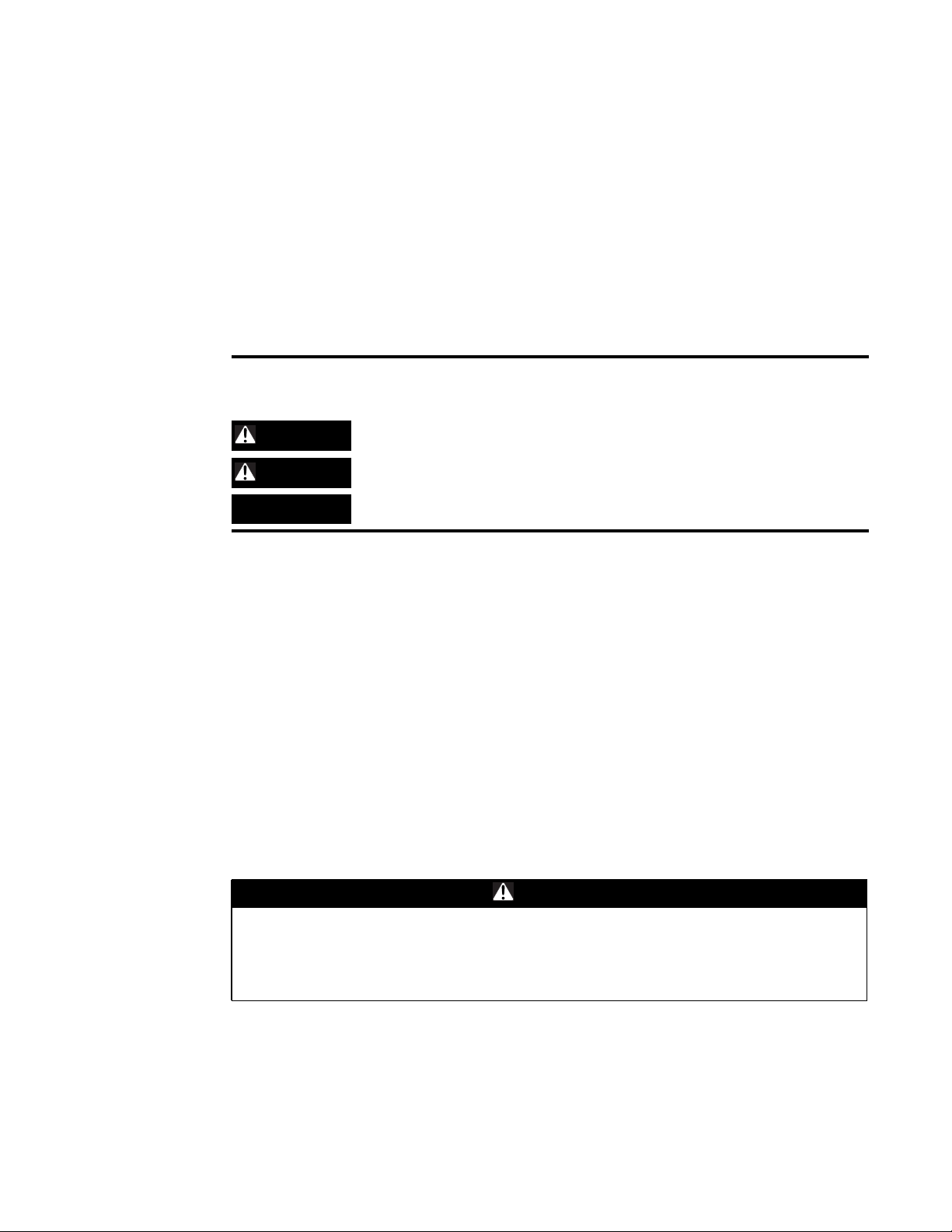
WARNING
CAUTIONs
NOTICE:
Indicates a potentially hazardous situation which, if not avoided, could result in
death or serious injury.
Indicates a potentially hazardous situation which, if not avoided, could result in
minor or moderate injury. It could also be used to alert against unsafe practices.
Indicates a situation that could result in equipment or property-damage only
accidents
Important
Environmental Concerns!
Scientific research has shown that certain man-made chemicals can affect the earth’s naturally
occurring stratospheric ozone layer when released to the atmosphere. In particular, several of the
identified chemicals that may affect the ozone layer are refrigerants that contain Chlorine, Fluorine
and Carbon (CFCs) and those containing Hydrogen, Chlorine, Fluorine and Carbon (HCFCs). Not all
refrigerants containing these compounds have the same potential impact to the environment.
Trane advocates the responsible handling of all refrigerants-including industry replacements for
CFCs such as HCFCs and HFCs.
Responsible Refrigerant Practices!
Trane believes that responsible refrigerant practices are important to the environment, our
customers, and the air conditioning industry. All technicians who handle refrigerants must be
certified.The Federal Clean Air Act (Section 608) sets forth the requirements for handling,
reclaiming, recovering and recycling of certain refrigerants and the equipment that is used in these
service procedures. In addition, some states or municipalities may have additional requirements
that must also be adhered to for responsible management of refrigerants. Know the applicable
laws and follow them.
WARNING
Proper Field Wiring and Grounding Required!
All field wiring MUST be performed by qualified personnel. Improperly installed and grounded
field wiring poses FIRE and ELECTROCUTION hazards. To avoid these hazards, you MUST
follow requirements for field wiring installation and grounding as described in NEC and your
local/state electrical codes. Failure to follow code could result in death or serious injury.
© 2011Trane All rights reserved RT-SVX22G-EN
Warnings, Cautions and Notices
WARNING
Personal Protective Equipment (PPE) Required!
Installing/servicing this unit could result in exposure to electrical, mechanical and chemical
hazards.
• Before installing/servicing this unit, technicians MUST put on all Personal Protective
Equipment (PPE) recommended for the work being undertaken. ALWAYS refer to appropriate
MSDS sheets and OSHA guidelines for proper PPE.
• When working with or around hazardous chemicals, ALWAYS refer to the appropriate MSDS
sheets and OSHA guidelines for information on allowable personal exposure levels, proper
respiratory protection and handling recommendations.
• If there is a risk of arc or flash, technicians MUST put on all Personal Protective Equipment
(PPE) in accordance with NFPA 70E or other country-specific requirements for arc flash
protection, PRIOR to servicing the unit.
Failure to follow recommendations could result in death or serious injury.
RT-SVX22G-EN 3

Table of Contents
Model Number Description ..............................................8
General Information ...................................................10
Unit Inspection ...................................................10
Model Number Notes .......................................... 9
Storage ..................................................... 10
Unit Nameplate .............................................. 10
Compressor Nameplate ....................................... 10
Unit Description .............................................. 10
Economizer Control Actuator (Optional) ..........................11
RTCI - ReliaTel™ Trane Communication Interface (Optional) ......... 11
RLCI - ReliaTel™ LonTalk Communication Interface (Optional) ....... 11
RBCI - ReliaTel™ BACnet™ Communications Interface (Optional) ..... 11
RTOM - ReliaTel™ Options Module (Standard on 17 Plus, 7.5 Ton & 8.5 Ton
High Efficiency with ReliaTel, 10 Ton with ReliaTel) ................ 11
System Input Devices & Functions .............................. 12
Low Pressure Control ......................................... 12
High Pressure Control .........................................13
Power Exhaust Control (Optional) ...............................13
Lead/Lag Control (Dual Circuit Only) .............................13
Zone Sensor Module (ZSM) (BAYSENS106*) ......................13
Zone Sensor Module (ZSM) (BAYSENS108*) ......................13
Zone Sensor (BAYSENS110*) ..................................14
Wall Mounted Relative Humidity Sensor (BAYSENS036*) ........... 14
Duct Mounted Relative Humidity Sensor (BAYSENS037*) ........... 14
Programmable Zone Sensor - (BAYSENS119*) .................... 14
Status Inputs (4 Wires Optional) ................................ 14
Remote Zone Sensor (BAYSENS073*) ........................... 14
Remote Zone Sensor (BAYSENS074*) ........................... 14
Remote Zone Sensor (BAYSENS016*) ........................... 15
Remote Zone Sensor (BAYSENS077*) ........................... 15
Wireless Zone Sensor (BAYSENS050*) ........................... 15
Electro Mechanical Control .....................................15
High Temperature Sensor (BAYFRST001A) ....................... 15
Evaporator Frost Control ...................................... 15
Discharge Line Temp Switch (DLTS) .............................16
Smoke Detector Sensor (Optional) .............................. 16
Phase Monitor ............................................... 16
Single Zone Variable Air Volume / Displacement Ventilation (Optional) 16
Pre-Installation ........................................................ 17
Unit Dimensions ....................................................... 18
Unit Clearances ...................................................18
Installation ............................................................25
Foundation .......................................................27
4 RT-SVX22G-EN

Table of Contents
Horizontal Units .............................................. 27
Ductwork ................................................... 29
Roof Curb ........................................................ 30
Downflow ................................................... 30
Rigging ..................................................... 31
General Unit Requirements ........................................33
Factory Installed Economizer ................................... 34
Temperature Limit Switch Usage for Electric Heat Units ............ 34
Horizontal Discharge Conversion (3 Through 5 Ton Units) ..............34
Horizontal Discharge Conversion (6 Through 10 Ton Units) .............34
TCO-A Instructions ........................................... 36
Return Air Smoke Detector ......................................... 37
Main Electrical Power Requirements .............................39
Electric Heat Requirements .................................... 39
Low Voltage Wiring (AC & DC) Requirements ..................... 39
Condensate Drain Configuration .................................... 39
To convert drain condensate through the base of unit: .............. 40
Filter Installation .................................................. 41
Field Installed Power Wiring ........................................ 41
Main Unit Power .................................................. 41
Standard Wiring ............................................. 42
Optional TBUE Wiring (Through the Base Electrical Option) ......... 42
Field Installed Control Wiring ...................................43
Control Power Transformer .................................... 43
Controls using 24 VAC ........................................ 43
Controls using DC Analog Input/Outputs (Standard Low Voltage Multi con-
ductor Wire) ................................................. 44
Smoke Detector Customer Low Voltage Wiring ....................... 50
Space Temperature Averaging (ReliaTel™ only) ...................... 51
Pre-Start .............................................................. 54
Voltage Imbalance ................................................ 54
Electrical Phasing (Three Phase Motors) ............................. 55
Compressor Crankcase Heaters (Optional/Standard with THC036-120E,
THC092F, TSC072-102E, TSC120F) ...............................56
ReliaTel™ Controls ........................................... 56
Test Modes ...................................................... 57
Electromechanical Controls Test Procedure ....................... 58
Start-Up .............................................................. 59
Verifying Proper Air Flow .......................................... 59
Units with 5-Tap Direct Drive Indoor Fan ......................... 59
Units with Belt Drive Indoor Fan ................................ 60
Units with Direct Drive Indoor Fan with MMC - Electromechanical Control
RT-SVX22G-EN 5

Table of Contents
61
ReliaTel units with Direct Drive Indoor Fan (7.5 - 10 Ton High Efficiency, 10
Ton) ........................................................ 61
Units with Constant CFM Direct Drive Indoor Fan .................. 63
Return Air Smoke Detector ......................................... 63
Economizer Start-Up .............................................. 64
Compressor Start-Up .............................................. 66
Dehumidification Option ........................................... 66
Final System Setup ............................................... 67
Maintenance .......................................................... 68
Fan Belt Adjustment - Belt Drive Units ............................... 68
Monthly Maintenance ............................................. 69
Filters ...................................................... 69
Return Air Smoke Detector Maintenance ......................... 69
Cooling Season .............................................. 69
Heating Season .............................................. 70
Coil Cleaning ................................................ 70
Annual Maintenance ..............................................72
Final Process ..................................................... 72
Troubleshooting ....................................................... 74
ReliaTel™ Control ................................................. 74
System Status Checkout Procedure ................................. 75
Method 1 ................................................... 75
System failure ............................................... 75
Cooling Failure ............................................... 75
Service Failure ............................................... 76
Simultaneous Heat and Cool Failure ............................. 76
Resetting Cooling and Ignition Lockouts .......................... 76
Method 1 ................................................... 77
Method 2 ................................................... 77
Zone Temperature Sensor (ZTS) Service Indicator .................... 77
Clogged Filter Switch ......................................... 77
Fan Failure Switch ............................................ 77
Zone Temperature Sensor (ZTS) Test ................................ 77
Test 1 - Zone Temperature Thermistor (ZTEMP) ................... 77
Test 2 - Cooling Set Point (CSP) and Heating Set Point (HSP) ........ 77
Test 3 - System Mode and Fan Selection ......................... 78
Test 4 - LED Indicator Test, (SYS ON, HEAT, COOL & SERVICE) ...... 78
Method 1 ................................................... 78
Method 2 ................................................... 78
Method 3 ................................................... 78
Relative Humidity Sensor Test .................................. 78
6 RT-SVX22G-EN

Table of Contents
Programmable & Digital Zone Sensor Test ....................... 79
ReliaTel Refrigeration Module (RTRM) Default Chart ............... 79
Unit Operation without a Zone Sensor ........................... 79
Unit Economizer Control (ECA) Troubleshooting ...................... 79
ReliaTel Control .............................................. 79
Electro Mechanical Control .....................................80
Unit Economizer Control (ECA) Test Procedures ...................... 80
Electro Mechanical Control .....................................80
Troubleshooting procedures for Direct Drive Plenum Fan .............. 81
Wiring Diagrams ...................................................... 83
Limited Warranty ...................................................... 85
Electric Air Conditioner ............................................ 85
TCY, TCX, TCC, TCD, TCH, TCM,TCP, TSC and THC (Parts Only) Models
Less Than 20 Tons for Residential Use* .......................... 85
Electric Air Conditioner ............................................ 86
TCY, TCX, TCC, TCD, TCH, TCK, TCM, TCP, TSC and THC (Parts Only) Mod-
els Less Than 20 Tons for Commercial Use* ...................... 86
RT-SVX22G-EN 7

Model Number Description
TSC 036 E 3 R Z B **
123 456 7 8 9 10 11 1213
Digit 1 - Unit Type
T DX Cooling
Digit2-Efficiency
S Standard Efficiency
H High Efficiency
Digit 3 - Airflow
C Convertible
Digit 4,5,6 - Nominal Gross
Cooling Capacity (MBh)
036 3Ton
037 3Ton (17 Plus)
047 4Ton (17 Plus)
048 4Ton
060 5Ton
067 5Ton (17 Plus)
072 6Ton
090 7½Ton, Single Compressor
092 7½Ton, Dual Compressor
102 8½ Ton
120 10 Ton
Digit 7 - Major Design Sequence
E R-410A Refrigerant
F MicrochannelType Condenser Coil
Digit 8 - Voltage Selection
1 208/230/60/1
3 208-230/60/3
4 460/60/3
W 575/60/3
Digit 9 - Unit Controls
E Electromechanical
R ReliaTel™ Microprocessor
Note: Electromechanical controls are not
available on 17 Plus two-stage
units. ReliaTel is standard.
Digit 10 - Heating Capacity
0=No Electric Heat F=14 kW (1 phase)
A=5 kW (1 phase)1G=18 kW (1&3 phase)
B=6 kW (3 phase) J=23 kW (3 phase)
C=9 kW (3 phase) K= 27 kW (3 phase)
D=10 kW (1 phase)
E=12 kW (3 phase) P = 54 kW (3 phase)
1
N = 36 kW (3 phase)
L Low Heat
M Medium Heat
H High Heat
X Low Heat, Stainless Steel Heat
Exchanger
Y Medium Heat, Stainless Steel Heat
Exchanger
Z High Heat, Stainless Steel Heat
Exchanger
Digit 11 - Minor Design Sequence
A First Sequence
B Second Sequence
21
20
Digit 12,13 - Service Sequence
** Factory Assigned
Digit 14 - Fresh Air Selection
0 No Fresh Air
A Manual Outside Air Damper 0-50%
B Motorized Outside Air Damper
0-5027%
C Economizer, Dry Bulb 0-100%
without Barometric Relief
D Economizer, Dry Bulb 0-100%
with Barometric Relief
E Economizer, Reference Enthalpy
0-100% without Barometric Relief
F Economizer, Reference Enthalpy
0-100% with Barometric Relief
G Economizer, Comparative
Enthalpy 0-100% without
Barometric Relief
3,7
H Economizer, Comparative
Enthalpy 0-100% with Barometric
3,7
Relief
Digit 15 - Supply Fan/Drive Type/
Motor
0 Standard Drive
1 Oversized Motor
2 Optional Belt Drive Motor
6 Single Zone VAV
24
7 Multi-Speed Indoor Fan
6
31
Digit 16 - Hinged Service Access/
Filters
0 Standard Panels/Standard Filters
A Hinged Access Panels/Standard
Filters
B Standard Panels/2” MERV 7 Filters
C Hinged Access Panels/2” MERV 7
Filters
D Standard Panels/2” MERV 13 Filters
E Hinged Access Panels/2” MERV 13
Filters
Digit 17 - Condenser Coil
Protection
1
0 Standard Coil
1 Standard Coil with Hail Guard
2 Black Epoxy Pre-Coated Condenser
25
Coil
3 Black Epoxy Pre-Coated Condenser
Coil with Hail Guard
4 CompleteCoat™ Condenser Coil
5 CompleteCoat™ Condenser Coil
with Hail Guard
25
Digit 18 - Through the Base
Provisions
4
Note: Applicable to Digit 1,T models.
0 NoThrough the Base Provisions
A Through the Base Electric
7
7
3,7
3,7
Digit 19 - Disconnect/Circuit
Breaker (three- phase only)
0 No Disconnect/No Circuit Breaker
1 Unit Mounted Non-Fused
Disconnect
2 Unit Mounted Circuit Breaker
8
8
8
Digit 20 - Convenience Outlet
0 No Convenience Outlet
A Unpaired Convenience Outlet
B Powered Convenience Outlet
(three-phase only)
9
Digit 21 - Communications
Options
0 No Communications Interface
1 Trane Communications Interface
18
28
2 LonTalk® Communications
3 Novar 2024 Controls
4 Never 3051 Controls without Zone
5 Novar 3051 Controls Interface with
6 BACnet™Communications
3
Interface
Sensor
29
DCV
Interface
29
29
Digit 22 - Refrigeration System
Option
0 Standard Refrigeration System
B Dehumidification
22,23
10
Digit 23 - Refrigeration Controls
Note: Applicable to Digit7=E.
0 No Refrigeration Control
1 Frostat
2 Crankcase Heater
3 Frostat
11 ,30
11 ,30
and Crankcase Heater
Digit 24 - Smoke Detector
0 No Smoke Detector
A Return Air Smoke Detector
B Supply Air Smoke Detector
C Supply and Return Air Smoke
Detectors
12,13
5
2
17
12,13
2
8 RT-SVX22G-EN

Model Number Description
Digit 25 - Monitoring Controls
0 No Monitoring Control
1 Clogged Filter Switch
2 Fan Failure Switch
3 Discharge Air SensingTube
4 Clogged Filter Switch and Fan
Fail Switch
5 Clogged Filter Switch and Discharge
Air Sensing Tube
6 Fan Fail Switch and Discharge Air
SensingTube
7 Clogged Filter and Fan Fail Switches
and Discharge Air SensingTube
8 Novar Return Air Sensor
9 Novar 3051 Zone Sensor
14
14
14
14
14
14
14
14
15
19
Model Number Notes
1. Available on 3-5 ton models.
2. Standard on all 15 SEER and all 6-
10Ton units.
3. Not available with
electromechanical controls.
4. Manual outside air damper will
ship factory supplied within the
unit, but must be field installed.
5. High pressure control is standard
on all units.
6. On 3-5 ton, multispeed direct drive
is standard on single phase and 15
SEER. On 6-10 ton, multispeed
direct drive is standard on all 10
ton and 7½ - 8½ ton high
efficiency. 17 Plus units use
constant CFM direct drive motors.
Belt drive is standard on all other
units.
Digit 15 = 0
Standard Efficiency
1 Phase = High Efficiency Multispeed Direct
Drive Motor
3 Phase (3-8½ Ton) = Belt Drive
3 Phase (10 T on) = Ultra High Efficiency Direct
Drive Plenum Fan
High Efficiency
1 Phase = High Efficiency Multispeed Direct
Drive Motor
3 Phase (17 Plus) = High Efficiency Constant
CFM Direct Drive Motor
3 Phase (3-5 ton) = High Efficiency Multispeed
Direct Drive Motor
3 Phase (3-5 ton w/Dehumidification) = Belt
Drive Motor
3 Phase (7½-10 ton) = Ultra High Efficiency
Direct Drive Plenum Fan
7. Economizer with Barometric
Relief is for downflow configured
units only. Order Economizer
without Barometric Relief for
horizontal configuration.
Barometric Relief for horizontal
configured units must be ordered
as field installed accessory.
8. Through the base electric required
when ordering disconnect/circuit
breaker options.
9. Requires use of Disconnect or
Circuit Breaker.
Not Available
Standard Efficiency
10 Ton w/575V
High Efficiency
3-5 ton w/Standard Indoor Motor w/460V
10. Standard metering devices are
TXVs.
11. Frostat cannot be field installed in
electro-mechanical units.
12. The return air smoke detector may
not fit up or work properly on the
units when used in conjunction
with 3rd party accessories such as
bolt on heat wheels, economizers
and power exhaust. Do not order
the return air smoke detectors
when using this type of accessory.
13. ReturnAir Smoke Detector cannot
be ordered with Novar Controls.
14. These options are standard when
ordering Novar Controls.
15. This option is used when ordering
Novar Controls.
16. Includes gas piping and shutoff
(field assembly required).
17. Not available with high
temperature duct sensor
accessory.
18. Digit 15 = 2
Standard Efficiency
1 Phase = Not Available
3 Phase = Not Available
High Efficiency
1 Phase = Not Available
3 Phase (3-5 ton) = May be Ordered
3 Phase (3-5 ton w/Dehumidification) = Not
Available
3 Phase (6-10 ton) = Not Available
19. Novar Sensor utilized with
Digit 21 = (4) Novar 3051 Controls
without Zone Sensor.
20. Available for 10 ton standard
efficiency models only.
21. Available for Y 3,4,5,6,7½,8½ ton
standard/high efficiency models
only.
22. Requires selection of 2 plated
filters (Digit 16, options B and C).
23. Not available on 6 ton units, and
all single phase or standard
efficiency units.
24. Standard on 10 ton standard
efficiency units and 7½ ton high
efficiency units (except
Dehumidification models)
25. Epoxy coil and epoxy coil with hail
guard options are not available
with Microchannel condenser
coils.
26. This option is only available on 17
Plus models.
27. Motorized Outside Air Damper is
not available on Multi-Speed or
SZVAV (Single Zone Variable Air
Volume) products.
28. Multi-speed indoor fan available
only on 7.5 & 8.5 ton high
efficiency, and 10 ton products
with ReliaTel™ controls.
29. Novar is not available with SZVAV
products.
30. Frostat standard on Multi-Speed
and SZVAV (Single Zone Variable
Air Volume) products.
31. Single Zone VAV is only available
on 7.5-10 ton high efficiency and 10
ton standard efficiency products
with ReliaTel™ controls.
RT-SVX22G-EN 9

General Information
Unit Inspection
As soon as the unit arrives at the job site
• Verify that the nameplate data matches the data on the sales order and bill of lading (including
electrical data).
• Verify that the power supply complies with the unit nameplate specifications.
• Visually inspect the exterior of the unit, including the roof, for signs of shipping damage.
If the job site inspection of the unit reveals damage or material shortages, file a claim with the
carrier immediately. Specify the type and extent of the damage on the “bill of lading” before
signing.
• Visually inspect the internal components for shipping damage as soon as possible after
delivery and before it is stored. Do not walk on the sheet metal base pans.
• If concealed damage is discovered, notify the carrier’s terminal of damage immediately by
phone and by mail. Concealed damage must be reported within 15 days.
• Request an immediate joint inspection of the damage by the carrier and the consignee. Do not
remove damaged material from the receiving location.Take photos of the damage, if possible.
The owner must provide reasonable evidence that the damage did not occur after delivery.
• Notify the appropriate sales representative before installing or repairing a damaged unit.
Storage
Take precautions to prevent condensate from forming inside the unit’s electrical compartments and
motors if:
1. the unit is stored before it is installed; or,
2. the unit is set on the roof curb, and temporary heat is provided in the building. Isolate all side
panel service entrances and base pan openings (e.g., conduit holes, S/A and R/A openings, and
flue openings) from the ambient air until the unit is ready for start-up.
Note: Do not use the unit’s heater for temporary heat without first completing the start-up
procedure detailed under “Starting the Unit”.
The manufacturer will not assume any responsibility for equipment damage resulting from
condensate accumulation on the unit’s electrical and/or mechanical components.
Unit Nameplate
A Mylar unit nameplate is located on the unit’s corner support next to the filter access panel. It
includes the unit model number,serial number,electrical characteristics,refrigerant charge,as well
as other pertinent unit data.
Compressor Nameplate
The nameplate for the compressors are located on the side of the compressor.
Unit Description
Before shipment, each unit is leak tested, dehydrated, charged with refrigerant and compressor oil,
and run tested for proper control operation.
The condenser coils are either aluminum fin, mechanically bonded to copper tubing, or all
aluminum microchannel type coil.
Direct-drive, vertical discharge condenser fans are provided with built-in thermal overload
protection.
There are two control systems offered for these units.The electro mechanical control option uses
a thermostat to perform unit functions.The ReliaTel™ Control Module is a microelectronic control
10 RT-SVX22G-EN

system that is referred to as “Refrigeration Module” (RTRM).The acronym RTRM is used
extensively throughout this document when referring to the control system network.
These modules through Proportional/Integral control algorithms perform specific unit functions
that governs unit operation in response to; zone temperature, supply air temperature, and/or
humidity conditions depending on the application.The stages of capacity control for these units
are achieved by starting and stopping the compressors.
The RTRM is mounted in the control panel and is factory wired to the respective internal
components.The RTRM receives and interprets information from other unit modules, sensors,
remote panels, and customer binary contacts to satisfy the applicable request for cooling.
Economizer Control Actuator (Optional)
Electro Mechanical Control
The ECA monitors the mixed air temperature, ambient dry bulb temperature and local minimum
position setpoint sensors, if selected, to control dampers to an accuracy of +/- 5% of stroke. The
actuator is spring returned to the closed position any time that power is lost to the unit. It is capable
of delivering up to 25 inch pounds of torque and is powered by 24 VAC.
ReliaTel™ Control
The ECA monitors the mixed air temperature, return air temperature, minimum position setpoint
(local or remote), power exhaust setpoint, CO
sensor or comparative humidity (return air humidity against ambient humidity) sensors, if
selected, to control dampers to an accuracy of +/- 5% of stroke.The actuator is spring returned to
the closed position any time that power is lost to the unit. It is capable of delivering up to 25 inch
pounds of torque and is powered by 24 VAC.
General Information
setpoint, CO2, and ambient dry bulb/enthalpy
2
RTCI - ReliaTel™ Trane Communication Interface (Optional)
This module is used when the application calls for an ICSTM building management type control
system. It allows the control and monitoring of the system through an ICS panel. The module can
be ordered from the factory or ordered as a kit to be field installed. Follow the installation
instruction that ships with each kit when field installation is necessary.
RLCI - ReliaTel™ LonTalk Communication Interface (Optional)
This module is used when the application calls for an ICSTM building management type control
system that is LonTalk. It allows the control and monitoring of the system through an ICS panel.
The module can be ordered from the factory or ordered as a kit to be field installed. Follow the
installation instruction that ships with each kit when field installation is necessary.
RBCI - ReliaTel™ BACnet™ Communications Interface (Optional)
This module is used when the application calls for an open BACnet protocol. It allows the control
and monitoring of the system through an ICS panel. The module can be ordered from the factory
or as a kit to be field installed. Follow the installation instructions that ships with eachkit when field
installation is necessary.
RTOM - ReliaTel™ Options Module (Standard on 17 Plus, 7.5 Ton & 8.5Ton High Efficiency with ReliaTel, 10 Ton with ReliaTel)
The RTOM monitors the supply fan proving, clogged filter, supply air temperature,Two-Stage 3-
5Ton High-Stage CFM setpoint, exhaust fan setpoint, supply air tempering, Frostat™, smoke
detector and Variable Fan Speed Control on 17 SEER. Refer to system input devices and functions
for operation.
RT-SVX22G-EN 11

General Information
System Input Devices & Functions
The RTRM must have a zone sensor or thermostat input in order to operate the unit.The flexibility
of having several mode capabilities depends upon the type of zone sensor or thermostat selected
to interface with the RTRM.
The descriptions of the following basic Input Devices used within the RTRM network are to acquaint
the operator with their function as they interface with the various modules. Refer to the unit’s
electrical schematic for the specific module connections.
The following controls are available from the factory for field installation.
Supply Fan Failure Input (Optional)
The Fan Failure Switch can be connected to sense indoor fan operation:
FFS (Fan Failure Switch) If air flow through the unit is not proven by the differential pressure switch
connected to the RTOM (factory set point 0.07 “w.c.) within 40 seconds nominally, the RTRM will
shut off all mechanical operations, lock the system out, send a diagnostic to ICS, and the SERVICE
output will flash.The system will remain locked out until a reset is initiated either manually or
through ICS.
Clogged Filter Switch (Optional)
The unit mounted clogged filter switch monitors the pressure differential across the return air
filters. It is mounted in the filter section and is connected to the RTOM. A diagnostic SERVICE signal
is sent to the remote panel if the pressure differential across the filters is at least 0.5" w.c.The
contacts will automatically open when the pressure differential across the filters decreases to
approximately 0.4" w.c.The clogged filter output is energized when the supply fan is operating and
the clogged filter switch has been closed for at least 2 minutes.The system will continue to operate
regardless of the status of the filter switch.
Note: On units equipped with factory installed MERV 13 filters, a clogged filter switch with
different pressure settings will be installed. This switch will close when the differential
pressure is approximately 0.8' w.c. and open when the differential falls to 0.7" w.c.
Compressor Disable (CPR1/2)
This input incorporates the low pressure control (LPC) of each refrigeration circuit and can be
activated by opening a field supplied contact installed on the LTB.
If this circuit is open before the compressor is started, the compressor will not be allowed to
operate. Anytime this circuit is opened for 1 continuous second during compressor operation, the
compressor for that circuit is immediately turned “Off”. The compressor will not be allowed to
restart for a minimum of 3 minutes should the contacts close.
If four consecutive open conditions occur during the first three minutes of operation, the
compressor for that circuit will be locked out, a diagnostic communicated to the remote panel (if
installed), and a manual reset will be required to restart the compressor.
Low Pressure Control
ReliaTel Control
When the LPC is opened for 1 continuous second, the compressor for that circuit is turned off
immediately.The compressor will not be allowed to restart for a minimum of 3 minutes.
If four consecutive open conditions occur during an active call for cooling, the compressor will be
locked out, a diagnostic communicated to ICS™, if applicable, and a manual reset required to
restart the compressor. On dual compressor units only the affected compressor circuit is locked
out.
12 RT-SVX22G-EN

Electromechanical Control
When the LPC is opened, the compressor for that circuit is turned off immediately.The compressor
will restart when the LPC closes.
High Pressure Control
ReliaTel Control
The high pressure controls are wired in series between the compressor outputs on the RTRM and
the compressor contactor coils. If the high pressure control switch opens, the RTRM senses a lack
of current while calling for cooling and locks the compressor out.
If four consecutive open conditions occur during an active call for cooling, the compressor will be
locked out, a diagnostic communicated to ICS™, if applicable, and a manual reset required to
restart the compressor. On dual compressor units only the affected compressor circuit is locked
out.
Electromechanical Control
When the HPC is opened, the compressor for that circuit is turned off immediately.The compressor
will restart when the HPC closes.
Power Exhaust Control (Optional)
ReliaTel Control
The power exhaust fan is started whenever the position of the economizer dampers meets or
exceed the power exhaust setpoint when the indoor fan is on.
With the optional ventilation override accessory, the power exhaust fan is independent of the
indoor fan.
The setpoint panel is located in the return air section and is factory set at 25%.
General Information
Electromechanical Control
The power exhaust fan is started whenever the indoor fan is on and the adjustable damper limit
switch DLS is closed.
Lead/Lag Control (Dual Circuit Only)
ReliaTel Control Only
Lead/Lag is a selectable input located on the RTRM.The RTRM is configured from the factory with
the Lead/Lag control disabled. To activate the Lead/Lag function, simply cut the wire connected to
J3-8 at the RTRM. When it is activated, each time the designated lead compressor is shut off due
to the load being satisfied, the lead compressor or refrigeration circuit switches. When the RTRM
is powered up, i.e. after a power failure, the control will default to the number one circuit
compressor. Lead/Lag is not available on Multi-Speed Indoor Fan, or Single Zone Variable Air
Volume (SZVAV) products.
Zone Sensor Module (ZSM) (BAYSENS106*)
This electronic sensor features three system switch settings (Heat, Cool, and Off) and two fan
settings (On and Auto). It is a manual changeover control with single setpoint. (Cooling Setpoint
Only)
Zone Sensor Module (ZSM) (BAYSENS108*)
This electronic sensor features four system switch settings (Heat, Cool, Auto, and Off) and two fan
settings (On and Auto). It is a manual or auto changeover control with dual setpoint capability. It
can be used with a remote zone temperature sensor BAYSENS077*.
RT-SVX22G-EN 13

General Information
Zone Sensor (BAYSENS110*)
This electronic sensor features four system switch settings (Heat, Cool, Auto, and Off) and two fan
settings (On and Auto) with four system status LED’s. It is a manual or auto changeovercontrol with
dual setpoint capability. It can be used with a remote zone temperature sensor BAYSENS077*.
Wall Mounted Relative Humidity Sensor (BAYSENS036*)
Field installed, wall mounted humidity sensor is used to control activation of Enhanced
Dehumidification and Hot Gas Reheat Dehumidification. Humidity set points can be selected for
relative humidity levels between 40% and 60% by adjusting the DEHUMID setting on the ReliaTel
Options Module. See Figure 40, p. 46.
Duct Mounted Relative Humidity Sensor (BAYSENS037*)
Field installed, duct mounted humidity sensor is used to control activation of Enhanced
Dehumidification and Hot Gas Reheat Dehumidification. Humidity set points can be selected for
relative humidity levels between 40% and 60% by adjusting the DEHUMID setting on the ReliaTel
Options Module. See Figure 40, p. 46.
Programmable Zone Sensor - (BAYSENS119*)
This 7 day programmable sensor features 2, 3 or 4 periods for Occupied or Unoccupied
programming per day. If the power is interrupted, the program is retained in permanent memory.
If power is off for an extended period of time, only the clock and day may have to be reset.
The Zone Sensor allows selection of 2, 3 or 4 system modes (Heat, Cool, Auto, and Off), two fan
modes (On and Auto). It has dual temperature selection with programmable start time capability.
The occupied cooling set point ranges between 45 and 98 degrees Fahrenheit.The heating set point
ranges between 43 and 96 degrees Fahrenheit.
A liquid crystal display (LCD) displays zone temperature, temperature set points, day of the week,
time, and operational mode symbols.
The Option Menu is used to enable or disable applicable functions, i.e.; Morning Warm-up,
Economizer minimum position override during unoccupied status, Fahrenheit or Centigrade,
Supply air tempering, Remote zone temperature sensor, 12/24 hour time display, Smart fan, and
Computed recovery.
During an occupied period, an auxiliary relay rated for 1.25 amps @ 30 volts AC with one set of
single pole double throw contacts is activated.
Status Inputs (4 Wires Optional)
The ZSM can be wired to receive four (4) operating status signals from the RTRM (HEAT, COOL,
SYSTEM “ON”, SERVICE).
Four (4) wires from the RTRM should be connected to the appropriate terminals (7, 8, 9 & 10) on the
ZSM.
Remote Zone Sensor (BAYSENS073*)
This electronic sensor features remote zone sensing and timed override with override cancellation.
It is used with aTrane Integrated Comfort™ building management system.
Remote Zone Sensor (BAYSENS074*)
This electronic sensor features single setpoint capability and timed override with override
cancellation. It is used with aTrane Integrated Comfort™ building management system.
14 RT-SVX22G-EN

Remote Zone Sensor (BAYSENS016*)
This bullet type temperature sensor can be used for outside air (ambient) sensing, return air
temperature sensing, supply air temperature sensing, remote temperature sensing (uncovered.
Wiring procedures vary according to the particular application and equipment involved. Refer to
the unit’s wiring diagrams for proper connections.
Remote Zone Sensor (BAYSENS077*)
This electronic sensor can be used with BAYSENS106*, 108*, 110*, 119* Remote Panels.When this
sensor is wired to a BAYSENS119* Remote Panel, wiring must be 18 AWG ShieldedTwisted Pair
(Belden 8760 or equivalent). Refer toThe specific Remote Panel for wiring details.
Wireless Zone Sensor (BAYSENS050*)
This electronic sensor features five system settings (Auto, Off, Cool, Heat, and Emergency Heat)
and with On and Auto fan settings. It is a manual or auto changeover control with dual setpoint
capability. Other features include a timed override function, lockable system settings, and
Fahrenheit or Celsius temperature display. Included with the wireless zone sensor will be a receiver
that is to be mounted inside the unit, a mounting bracket, and a wire harness.
Electro Mechanical Control
The unit must have aThermostat to operate.
•BAYSTAT151
• Single Stage - 1 Heat/1 Cool
•BAYSTAT155
• Multi Stage - 3 Heat/2 Cool - Can be Used for Economizer Operation
• BAYSENS150
• Multi stage - 3 Heat/2 Cool Programmable Thermostat
General Information
High Temperature Sensor (BAYFRST001A)
This sensor connects to the RTRM Emergency Stop Input on the LTB and provides high limit
“shutdown” of the unit.The sensor is used to detect high temperatures due to fire in the air
conditioning or ventilation ducts.The sensor is designed to mount directly to the sheet metal duct.
Each kit contains two sensors.The return air duct sensor (X1310004001) is set to open at 135ºF.The
supply air duct sensor (X1310004002) is set to open at 240ºF. The control can be reset after the
temperature has been lowered approximately 25ºF below the cutout setpoint.
Evaporator Frost Control
ReliaTel™ Option
This input incorporates the Frostat™ control (FOS) mounted in the indoor coil circuit and can be
activated by closing a field supplied contact installed in parallel with the FOS.
If this circuit is open before the compressor is started, the compressor will not be allowed to
operate. Anytime this circuit is opened for 1 continuous second during compressor operation, the
compressor for that circuit is immediately turned “Off”. The compressor will not be allowed to
restart for a minimum of 3 minutes should the FOS close.
Frostat is standard on multi-speed indoor motors and single zone VAV products (SZVAV).
Electro Mechanical Option
This input incorporates the Frostat™ control (FOS) mounted in the indoor coil circuit and can be
activated by opening a field supplied contact installed in series with the FOS.
RT-SVX22G-EN 15

General Information
If this circuit is open before the compressor is started, the compressor will not be allowed to
operate. Anytime this circuit is opened during compressor operation, the compressor for that
circuit is immediately turned “Off”. The compressor will restart when the FOS closes.
Discharge LineTemp Switch (DLTS)
The DLTS is looped in series with HPC and LPC. It prevents compressor from overheating (over 300
Fº dome temp) in case of ID fan failure (cooling) or OD fan failure (heating).
Smoke Detector Sensor (Optional)
It provides high limit “shutdown” of the unit and requires a manual reset.The sensor is used to
detect smoke in the air conditioning or ventilation ducts.
Note: The supply and return air smoke detectors are designed to shut off the unit if smoke is
sensed in the supply air stream or return air stream.This function is performed by sampling
the airflow entering the unit at the return air opening. Follow the instructions provided
below to assure that the airflow through the unit is sufficient for adequate sampling. Failure
to follow these instructions will prevent the smoke detectors from performing it's design
function.
Note: Airflow through the unit is affected by the amount of dirt and debris accumulated on the
indoor coil and filters.To insure that airflow through the unit is adequate for proper
sampling by the return air smoke detector, complete adherence to the maintenance
procedures, including recommended intervals between filter changes, and coil cleaning is
required.
Note: Periodic checks and maintenance procedures must be performed on the smoke detector to
insure that it will function properly. For detailed instructions concerning these checks and
procedures, refer to the appropriate section(s) of the smoke detector Installation and
Maintenance Instructions provided with the literature package for this unit.
In order for the supply air smoke detector or return air smoke detector to properly sense smoke
in the supply air stream or return air stream, the air velocity entering the smoke detector unit must
be between 500 and 4000 feet per minute. Equipment covered in this manual will develop an
airflow velocity that falls within these limits over the entire airflow range specified in the evaporator
fan performance tables.
There are certain models, however, if operated at low airflow, will not develop an airflow velocity
that falls within the required 500 to 4000 feet per minute range. For these models, the design airflow
shall be greater than or equal to 1000 feet per minute MINIMUM.
Phase Monitor
This sensor monitors voltage between the 3 conductors of the 3 phase power supply.Two LED
lights are provided:
• The green light indicates that a balanced 3 phase supply circuit is properly connected.
• The red light indicates that unit operation has been prevented. There are two conditions that
will prevent unit operation:
• The power supply circuit is not balanced with the proper phase sequence of L1, L2, L3 for
the 3 conductors of a 3 phase circuit.
• The line to line voltage is not between 180 volts and 633 volts.
Single Zone Variable Air Volume / Displacement Ventilation (Optional)
This sensor offers full supply fan modulation across the available airflow range. In addition to full
supply fan modulation, the unit controls the discharge air temperature to a varying discharge air
temperature setpoint in order to maintain SpaceTemperature.
16 RT-SVX22G-EN

Pre-Installation
Fiberglass Wool!
Product contains fiberglass wool. Disturbing the insulation in this product during installation,
maintenance or repair will expose you to airborne particles of glass wool fibers and ceramic
fibers known to the state of California to cause cancer through inhalation. You MUST wear all
necessary Personal Protective Equipment (PPE) including gloves, eye protection, mask, long
sleeves and pants when working with products containing fiberglass wool. Exposition to glass
wool fibers without all necessary PPE equipment could result in cancer, respiratory, skin or eye
irritation, which could result in death or serious injury.
Precautionary Measures
• Avoid breathing fiberglass dust.
• Use a NIOSH approved dust/mist respirator.
• Avoid contact with the skin or eyes. Wear long-sleeved, loose-fitting clothing, gloves, and eye
protection.
• Wash clothes separately from other clothing: rinse washer thoroughly.
• Operations such as sawing, blowing, tear-out, and spraying may generate fiber concentrations
requiring additional respiratory protection. Use the appropriate NIOSH approved respiration in
these situations.
First Aid Measures
Eye Contact - Flush eyes with water to remove dust. If symptoms persist, seek medical attention.
Skin Contact - Wash affected areas gently with soap and warm water after handling.
WARNING
WARNING
Hazardous Voltage!
Disconnect all electric power, including remote disconnects before servicing. Follow proper
lockout/tagout procedures to ensure the power can not be inadvertently energized. Failure to
disconnect power before servicing could result in death or serious injury.
Remove power to the unit and gain access to the electric heat elements by removing the horizontal
supply cover.Visually inspect the heater elements for the following:
• Elements that are no longer secured to the white ceramic insulator.
• Elements touching each other or touching metal.
• Severely kinked, drooping, or broken elements.
If an element has detached from its ceramic insulator, carefully put it back into place.
Replace the heater elements if they present symptoms noted in item 2 or 3 above.
RT-SVX22G-EN 17
Unit Dimensions
TSC036-060E & THC036-037E Units
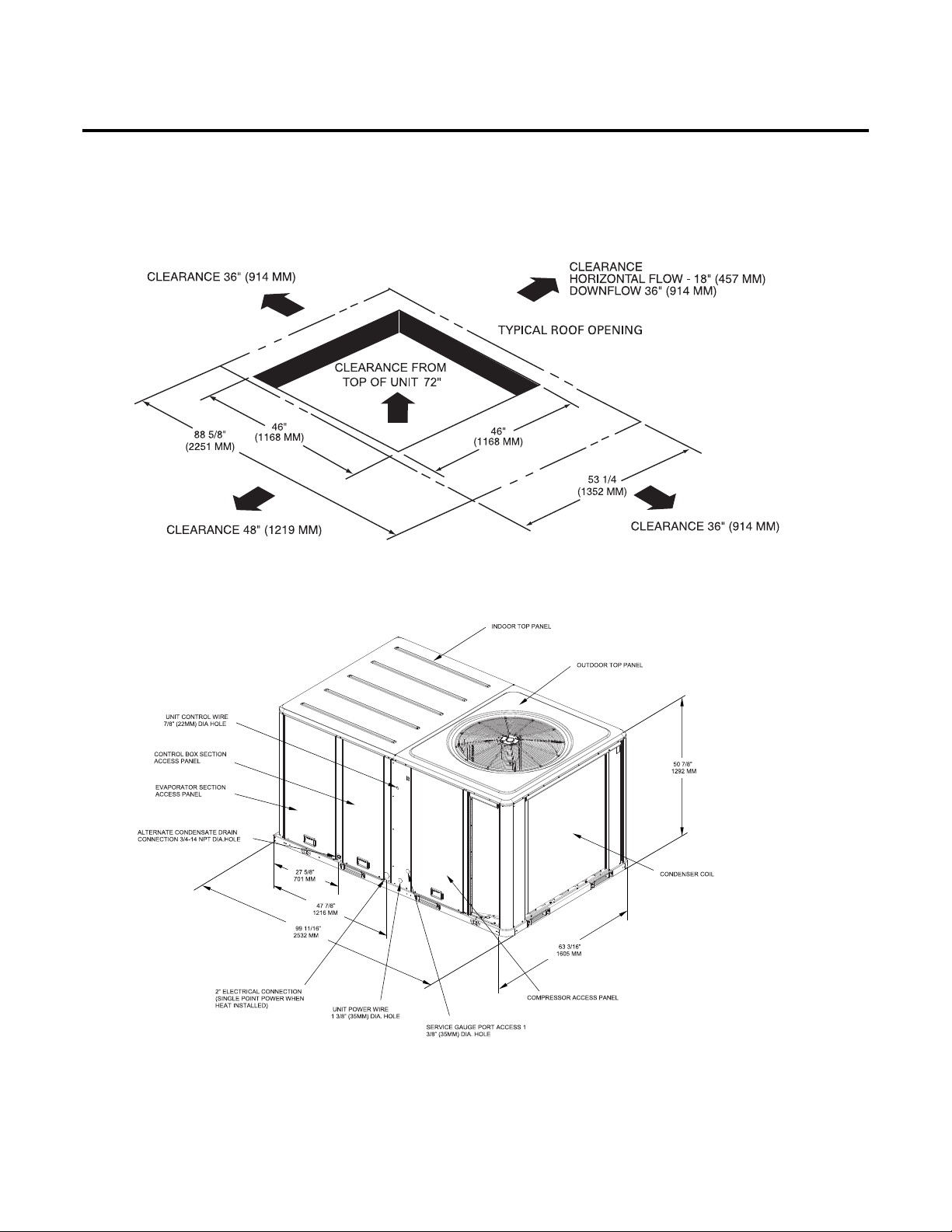
TSC072-102E, TSC120F, THC047-120E, & THC092F Units
Unit Clearances
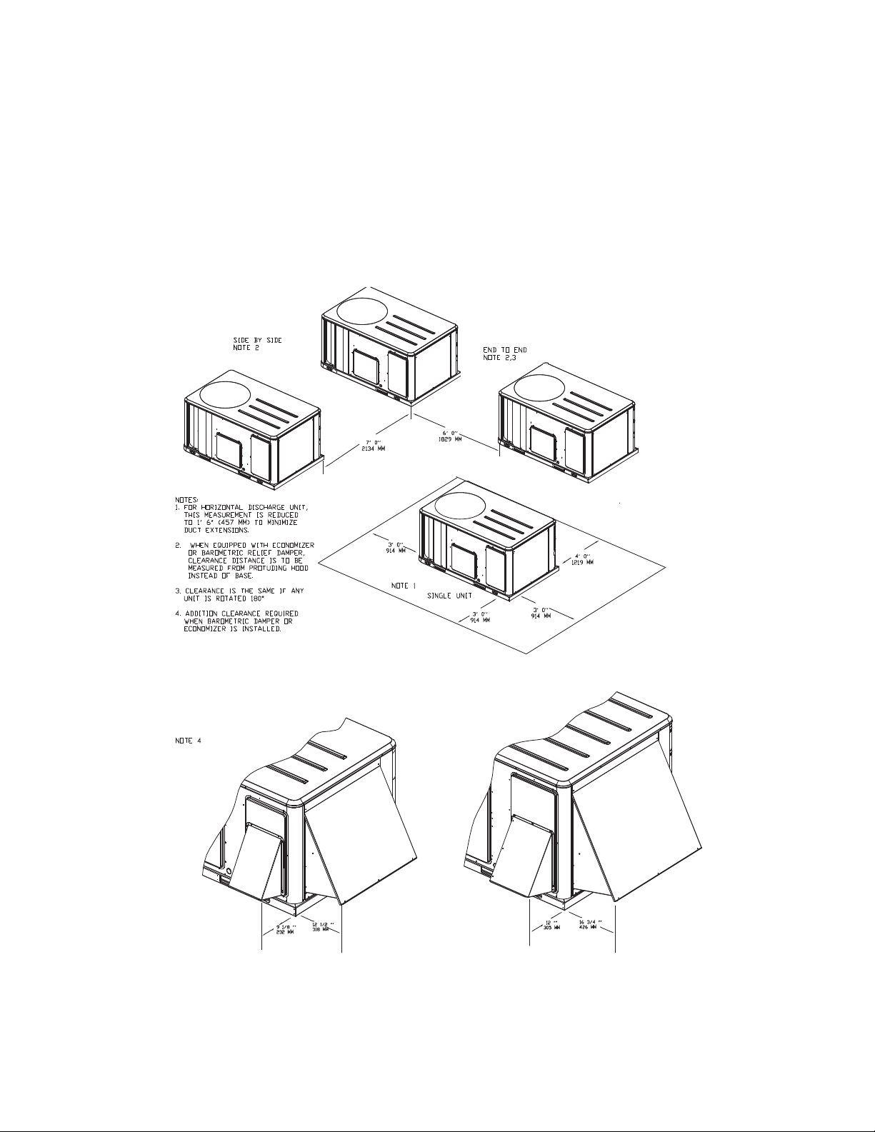
Figure 1, p. 18 illustrates the minimum operating and service clearances for either a single or
multiple unit installation.These clearances are the minimum distances necessary to assure
adequate serviceability, cataloged unit capacity, and peak operating efficiency.
Figure 1. Typical installation clearances for single & multiple unit applications
TSC036-060E & THC036-037E Units
Providing less than the recommended clearances may result in condenser coil starvation, “shortcircuiting” of exhaust and economizer airflows, or recirculation of hot condenser air.
18 RT-SVX22G-EN
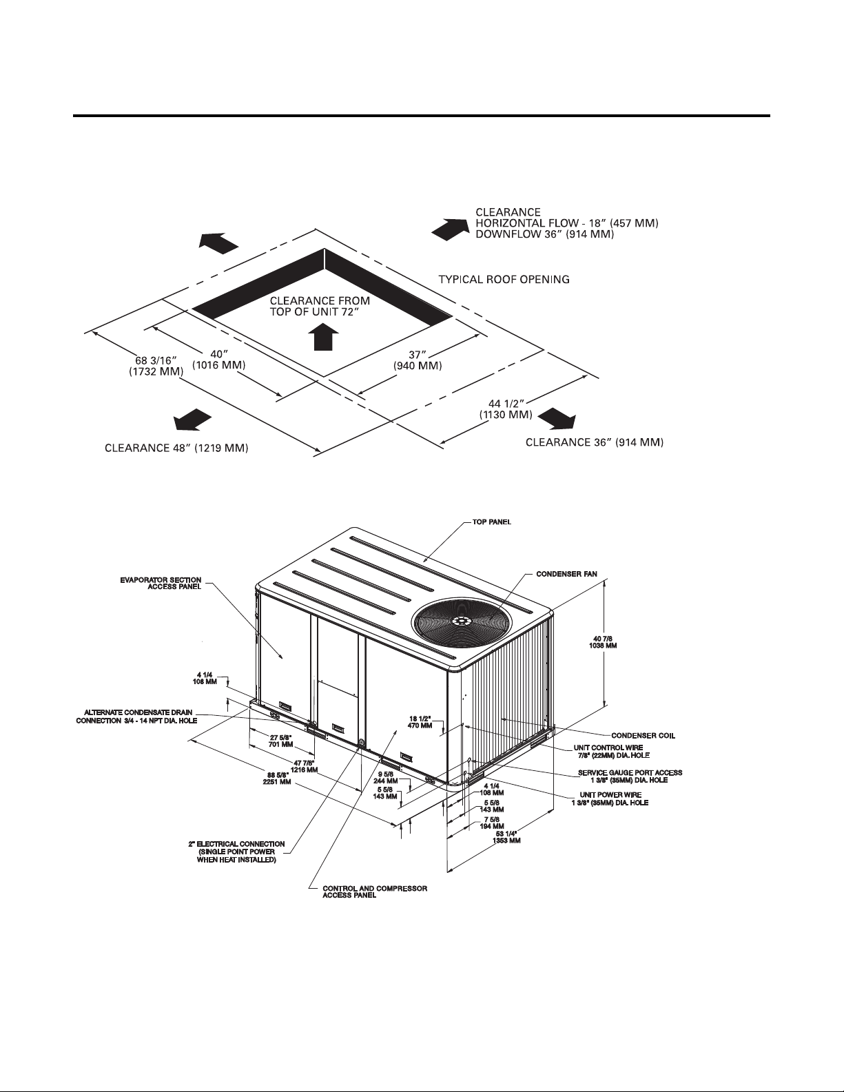
TSC072-102E, TSC120F, THC047-120E, & THC092F Units
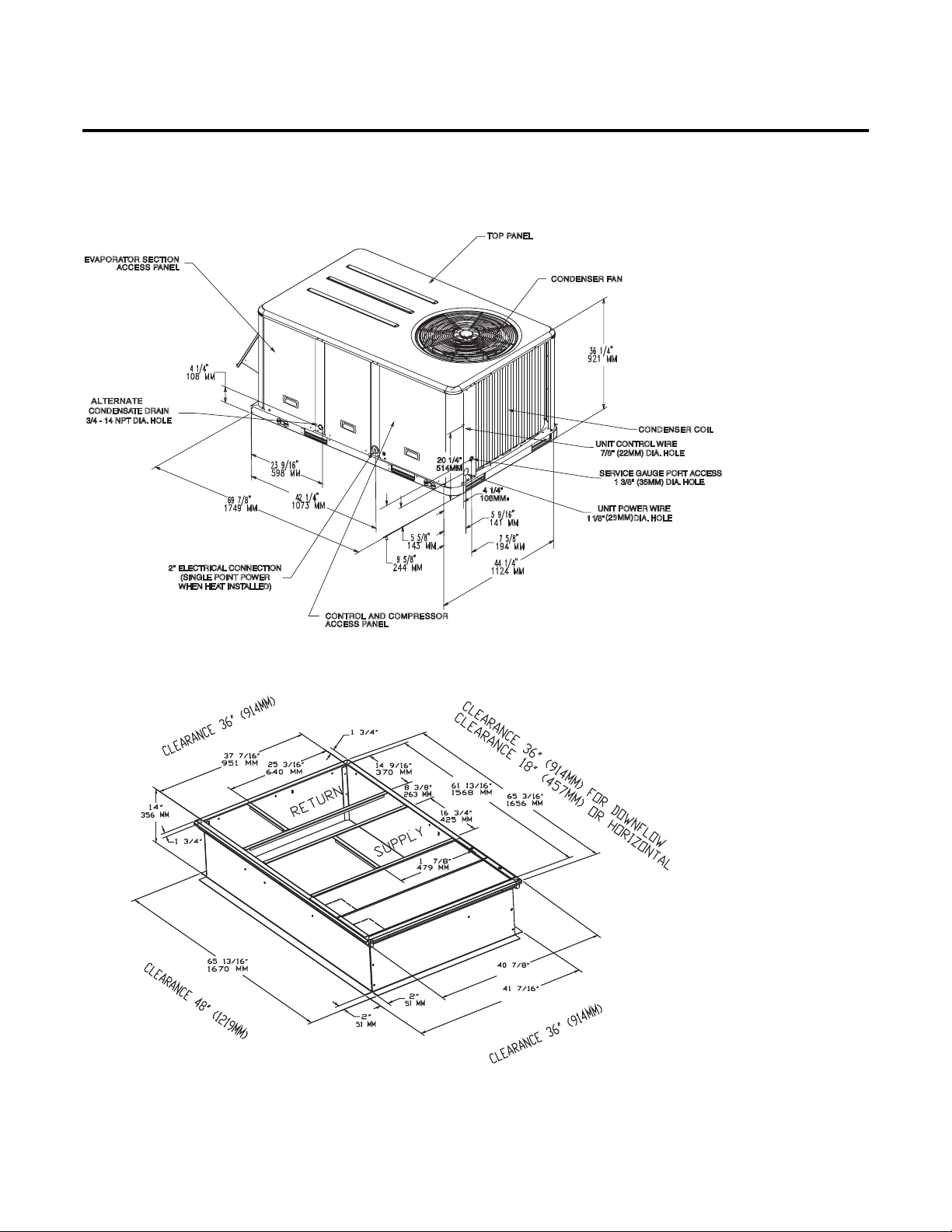
Figure 2. 3-5 ton standard efficiency, 3 ton high efficiency
44 MMMM
44 MMMM
1038 MMMM
1053 MMMM
Note: All dimensions are in inches/millimeters.
Unit Dimensions
Figure 3. 3-5 ton standard efficiency, 3 ton high efficiency - roof curb
Note: All dimensions are in inches/millimeters.
44
44
7
1038
1053
RT-SVX22G-EN 19
Unit Dimensions
Figure 4. 3-5 ton standard efficiency, 3 ton high efficiency - unit clearance and roof opening
Note: All dimensions are in inches/millimeters.
CLEARANCE 36” (914 MM)
Figure 5. 6, 7½ (single) ton standard efficiency,4-5tonhigh efficiency
Note: All dimensions are in inches/millimeters.
20 RT-SVX22G-EN
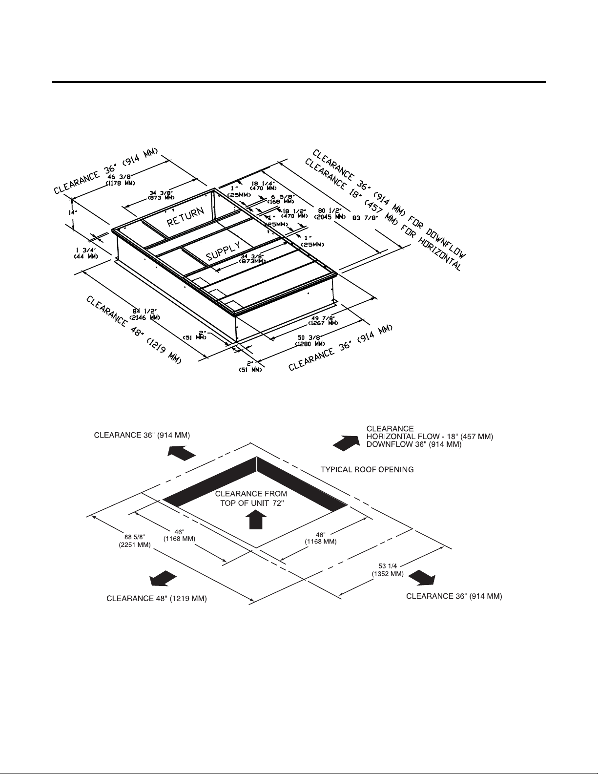
Figure 6. 6, 7½ (single) ton standard efficiency,4-5tonhigh efficiency - roof curb
Note: All dimensions are in inches/millimeters.
Unit Dimensions
(356 MM)
(2130 MM)
Figure 7. 6, 7½ (single) ton standard efficiency,4-5tonhigh efficiency - unit clearance and roof opening
Note: All dimensions are in inches/millimeters.
RT-SVX22G-EN 21
Unit Dimensions
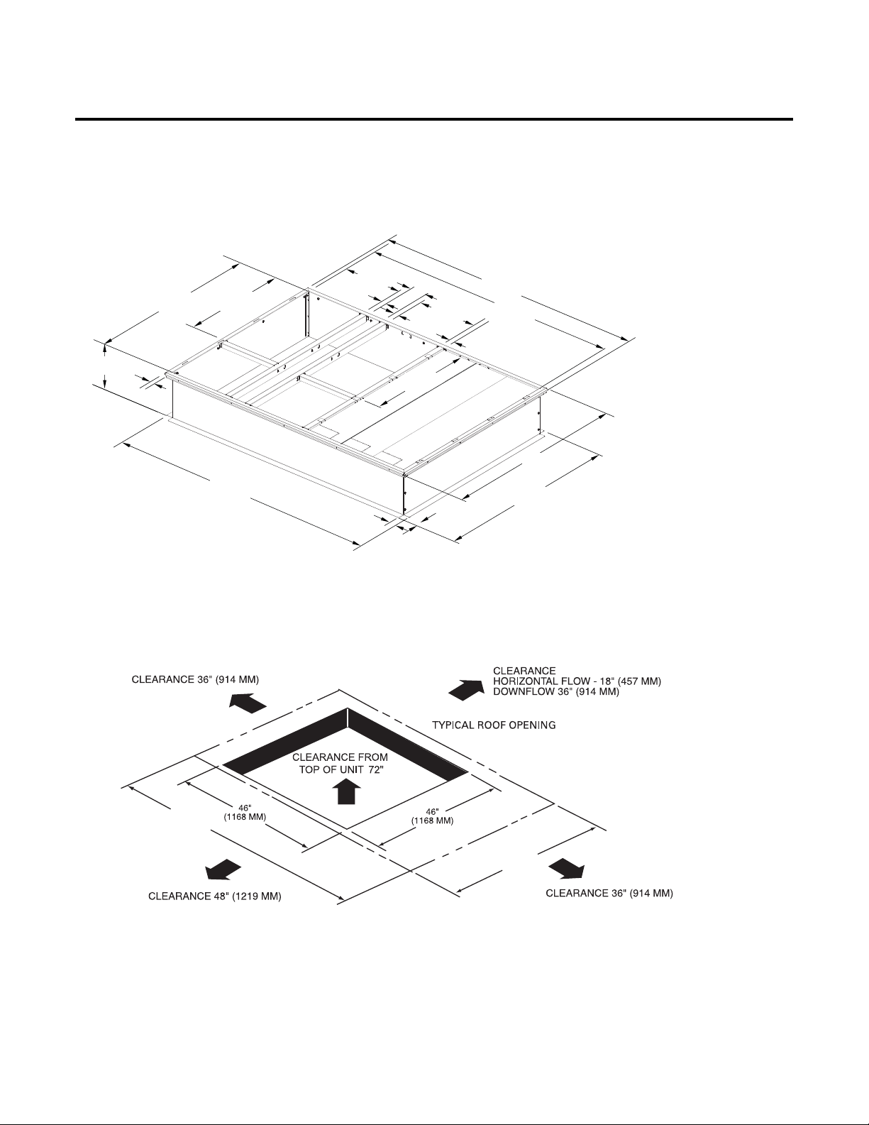
Figure 8. 7½ ton (dual) - 10 ton standard efficiency,6&7½(microchannel) ton high efficiency
Note: All dimensions are in inches/millimeters.
Figure 9. 7½ ton (dual) - 10 ton standard efficiency,6&7½(microchannel) ton high efficiency - roof curb
Note: All dimensions are in inches/millimeters.
(356 MM)
(2130 MM)
22 RT-SVX22G-EN
Unit Dimensions
Figure 10. 7½ ton (dual) - 10 ton standard efficiency,6&7½(microchannel) ton high efficiency - unit clearance and
roof opening
Note: All dimensions are in inches/millimeters.
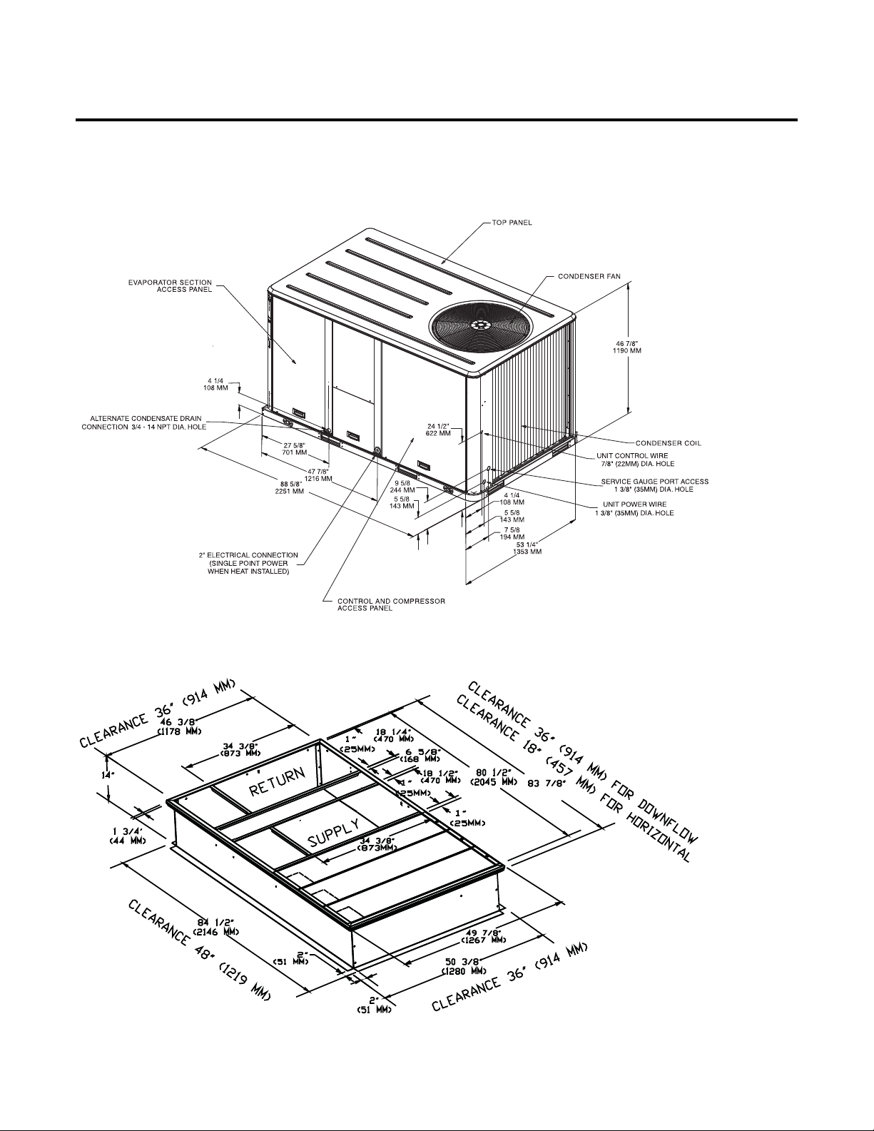
Figure 11. 7½ (dehumidification) - 10 ton high efficiency
Note: All dimensions are in inches/millimeters.
RT-SVX22G-EN 23
Unit Dimensions
(
)
(
)
(
)
(
)
(
)
(
)
(
)
(
)
(
)
Figure 12. 7½ (dehumidification) - 10 ton high efficiency - roof curb
Note: All dimensions are in inches/millimeters.
CLEARAN
C
CL
EARANCE 18” (4
18 1/2”
14”
356 MM
13/4”
44 MM
56 3/8”
(1432 MM)
34 3/8”
(873 MM)
84 1/2”
(2146 MM)
25 MM
1”
51 MM
(470 MM)
2”
51 MM
65/8”
168 MM
18 1/2”
(470 MM)
1”
25 MM
25 MM
34 3/8”
(873 MM)
2”
E36”(914MM)
57 MM
83 7/8”
(2130 MM)
(2045 MM)
1”
)
FO
80 1/2”
(1534 MM)
FO
R
H
60 3/8”
R
DO
O
WNF
RI
ZO
59 7/8”
1521 MM
LOW
NTAL
Figure 13. 7½ (dehumidification) - 10 ton high efficiency- unit clearance and roof opening
Note: All dimensions are in inches/millimeters.
99 11/16”
(2532 MM)
63 3/16”
(1605 MM)
24 RT-SVX22G-EN
Installation
WARNING
Heavy Objects!
Ensure that all the lifting equipment used is properly rated for the weight of the unit being
lifted. Each of the cables (chains or slings), hooks, and shackles used to lift the unit must be
capable of supporting the entire weight of the unit. Lifting cables (chains or slings) may not be
of the same length. Adjust as necessary for even unit lift. Other lifting arrangements could
cause equipment or property damage. Failure to follow instructions above or properly lift unit
could result in unit dropping and possibly crushing operator/technician which could result in
death or serious injury.
WARNING
Improper Unit Lift!
Test lift unit approximately 24 inches to verify proper center of gravity lift point. To avoid
dropping of unit, reposition lifting point if unit is not level. Failure to properly lift unit could
result in unit dropping and possibly crushing operator/technician which could result in death
or serious injury and possible equipment or property-only damage.
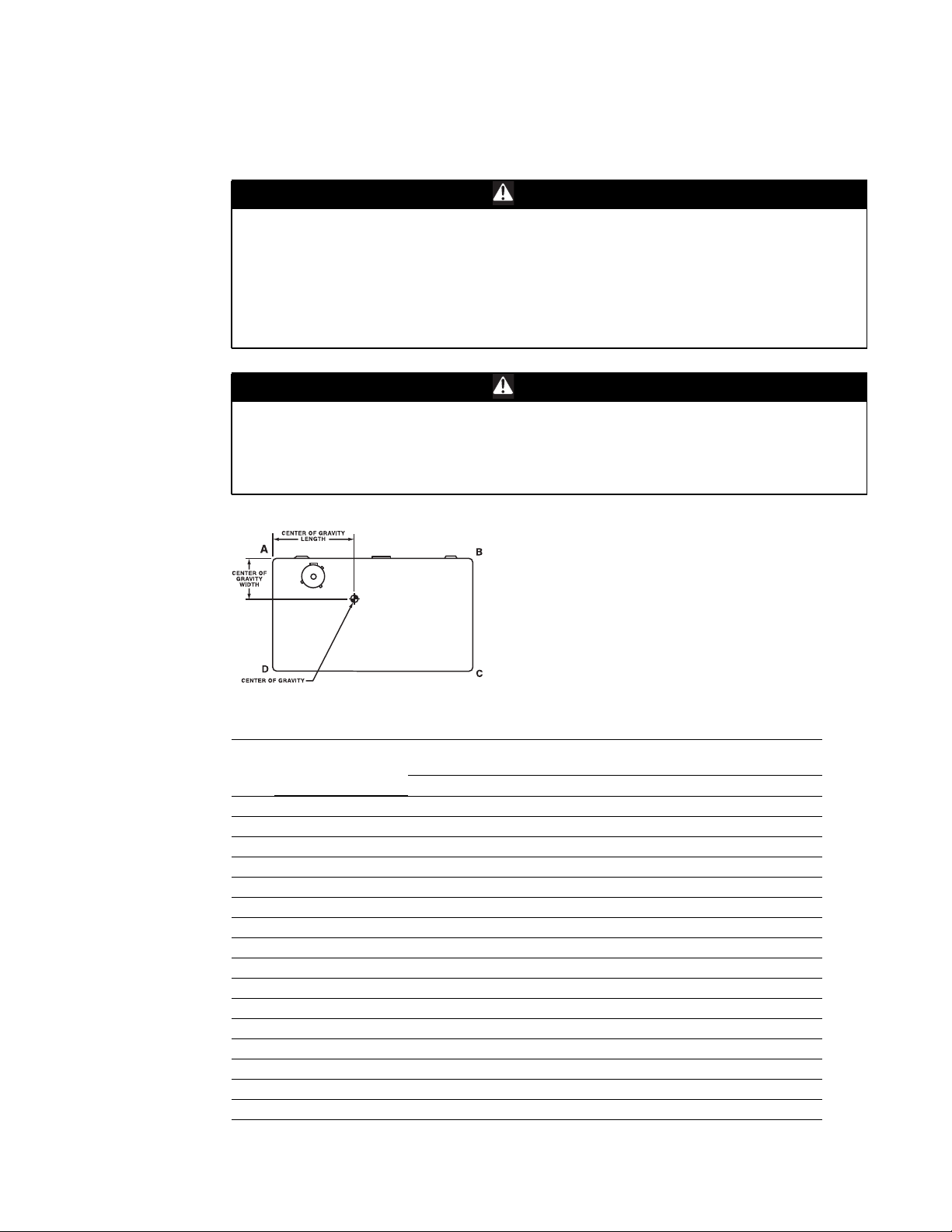
Figure 14. Corner weights
Table 1. Maximum unit & corner weights (lbs) and center of gravity dimensions (in.) - cooling
models
Maximum Model
Unit
Ton Shipping Net A B C D Length Width
3 TSC036E 555 481 157 122 95 107 31 19
4 TSC048E 586 511 167 129 101 114 31 19
5 TSC060E 636 561 183 142 111 125 31 19
6 TSC072E 815 720 231 187 135 167 40 22
7½ TSC090E 834 739 235 196 140 168 40 22
7½ TSC092E 992 849 354 147 252 96 42 22
8½ TSC102E 1048 905 359 161 265 120 42 23
10 TSC120F 1058 960 320 218 233 189 40 24
3 THC036E/THC037E 614 544 163 144 111 125 33 19
4 THC048E/THC047E 787 692 220 178 132 163 40 23
5 THC060E/THC067E 841 746 241 193 139 173 39 22
6 THC072E 915 818 252 224 161 181 42 22
7½ THC092E 1445 1228 347 330 269 283 49 28
7½ THC092F 1026 928 315 209 224 180 40 24
8½ THC102E 1472 1255 359 335 271 290 48 28
10 THC120E 1462 1245 353 332 271 288 48 28
(a)Weights are approximate.
(b)Corner weights are given for information only.
RT-SVX22G-EN 25
Model No.
Weights
(a)
Corner Weights
(b)
Center of Gravity
(in.)
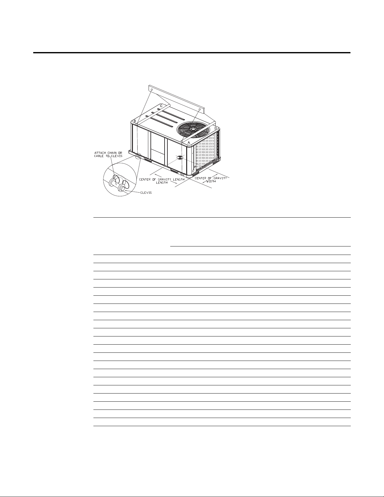
Installation
Figure 15. Rigging and center of gravity
Table 2. Factory installed options (fiops)/accessory net weights (lbs)
(a),(b)
TSC036E-060E
THC036E/
THC037E
THC047E-
067E
TSC072E-102E
THC072E
THC092F,
TSC120F
THC092E-
120E
Net Weight Net Weight Net Weight Net Weight Net Weight
Accessory 3-5 Ton 4-5 Ton 6-8½ Ton 7½-10 Ton 7½-10 Ton
Barometric Relief 7 10 10 10 10
Belt Drive Option (3 phase only) 31 31 — — —
Coil Guards 12 20 20 20 30
Economizer 26 36 36 36 36
Electric Heaters 15 30 30 40 40
Hinged Doors 10 12 12 12 12
Manual Outside Air Damper 16 26 26 26 26
Motorized Outside Air Damper 20 30 30 30 30
Novar Control 8 8 8 8 8
Oversized Motor 5 8 8 — —
Powered Convenience Outlet 38 38 38 38 50
Powered Exhaust 40 40 80 80 80
Reheat Coil 15 25 — — 53
Roof Curb 61 78 78 78 89
Smoke Detector, Supply 5 5 5 5 5
Smoke Detector, Return 7 7 7 7 7
Stainless Steel Heat Exchanger 4 6 6 6 6
Through the Base Electrical 8 13 13 13 13
Unit Mounted Circuit Breaker 5 5 5 5 5
Unit Mounted Disconnect 5 5 5 5 5
460V IDM
(a)Weights for options not listed are <5 lbs.
(b)Net weight should be added to unit weight when ordering factory-installed accessories.
(c) Apply weight with all 460V 17 SEER Two-Stage Cooling units.
(c)
29 29 - - -
26 RT-SVX22G-EN
Foundation
Horizontal Units
Installation
If the unit is installed at ground level, elevate it above the snow line. Provide concrete footings at
each support location with a “full perimeter” support structure or a slab foundation for support.
Refer to Table 1, p. 25 for the unit’s operating and point loading weights when constructing a
footing foundation.
If anchoring is required, anchor the unit to the slab using hold down bolts or isolators. Isolators
should be installed to minimize the transmission of vibrations into the building.
For rooftop applications, ensure the roof is strong enough to support the combined unit and
support structural weight. Refer to Table 1, p. 25 for the unit operating weights. If anchoring is
required, anchor the unit to the roof with hold-down bolts or isolators.
Check with a roofing contractor for proper waterproofing procedures.
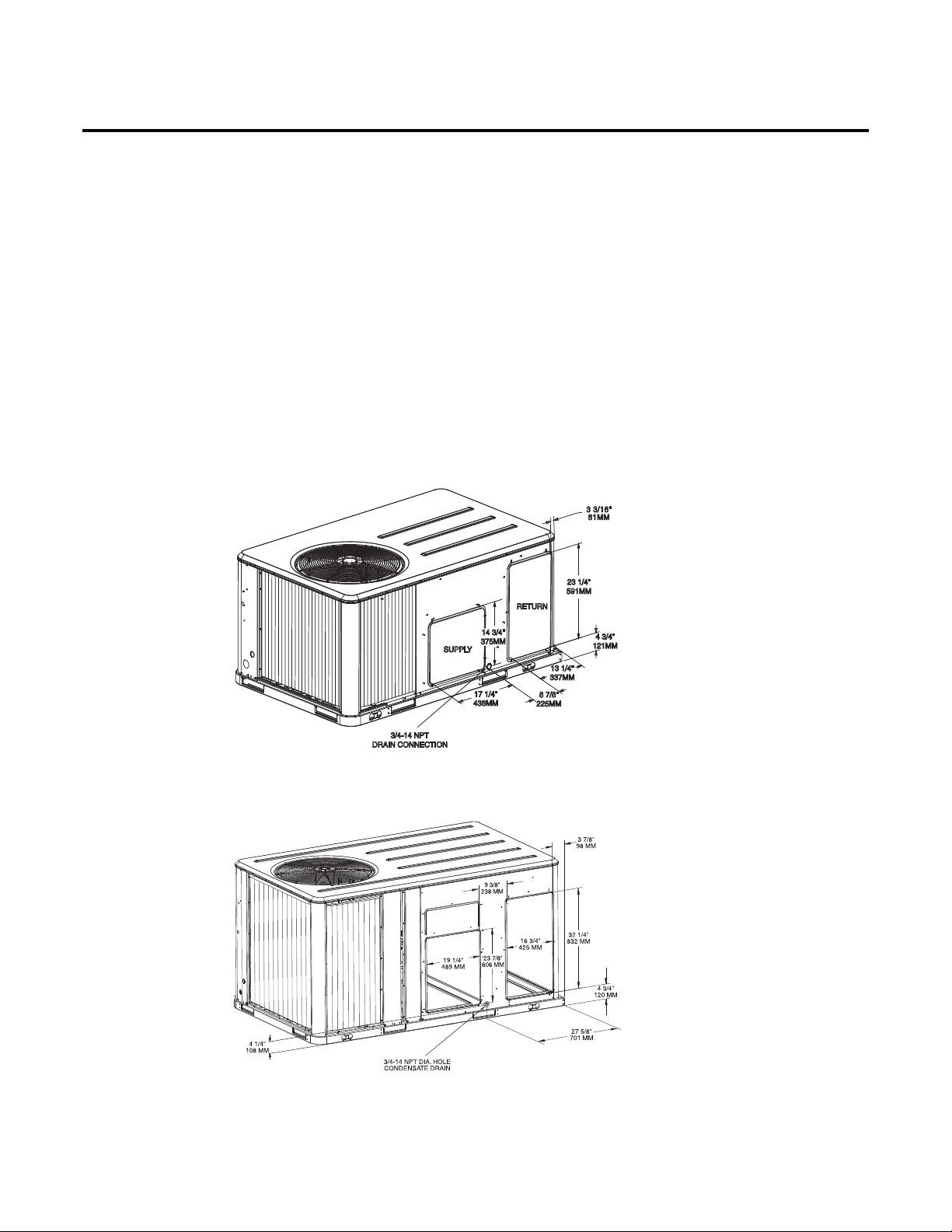
Figure 16. 3-5 ton standard efficiency units & 3 ton high efficiency units - Horizontal supply &
return air openings
Figure 17. 4-6/ 7½ (MCHE) ton high efficiency units and 6-10 ton standard efficiency units -
Horizontal supply & return air openings
Return
Supply
Figure 18. 7½ (dehumidification) - 10 ton high efficiency units - Horizontal supply & return air
openings
RT-SVX22G-EN 27
 Loading...