

Ingersoll-Rand TEM6A0B24H21S, TEM6A0C48H41S, TEM6A0B30H21S, TEM6A0D48H41S, TEM6A0D60H51S Installer's Manual
...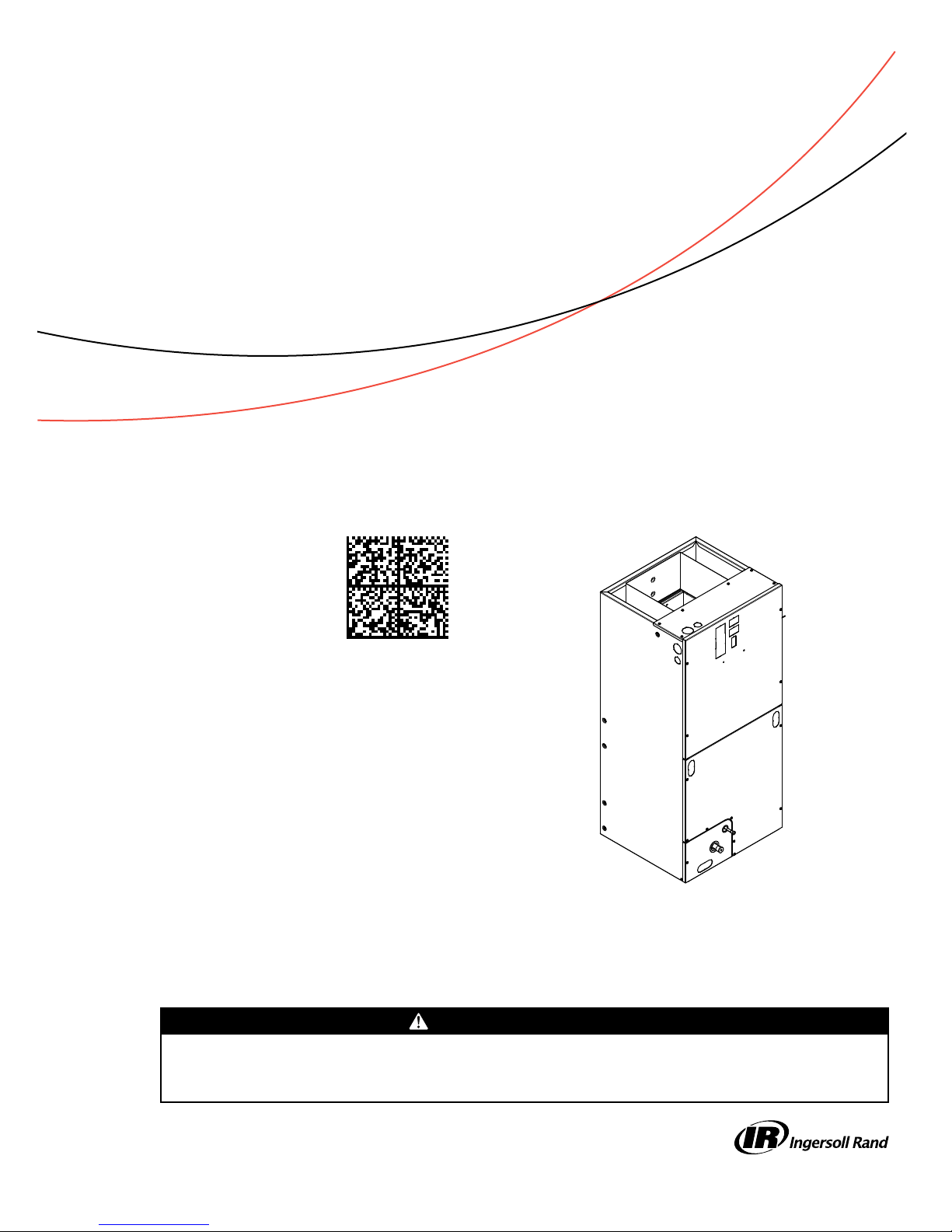
Installer’s Guide
Convertible Air Handlers
2 — 5 Ton
TEM6A0B24H21S
TEM6A0B30H21S
TEM6A0C36H31S
TEM6A0C42H41S
TEM6A0C48H41S
TEM6A0D48H41S
TEM6A0C60H51S
TEM6A0D60H51S
Only qualified personnel should install and service the equipment. The installation, starting up, and servicing of heating, ventilating, and
air-conditioning equipment can be hazardous and requires specific knowledge and training. Improperly installed, adjusted or altered
equipment by an unqualified person could result in death or serious injury. When working on the equipment, observe all precautions in the
literature and on the tags, stickers, and labels that are attached to the equipment.
January 2016
The TEM6 series air handler is designed for installation in a closet,
utility room, alcove, basement, crawlspace or attic. These versatile
units are applicable to air conditioning and heat pump
applications. Several models are available to meet the specific
requirements of the outdoor equipment. Field installed electric
resistance heaters are available.
SSAAFFEETTYY WWAARRNNIINNGG
18-GF74D1-1F-EN
SAFETY SECTION
AIR HANDLERS
IImmppoorrttaanntt:: This document contains a wiring diagram,
a parts list, and service information. This is
customer property and is to remain with
this unit. Please return to service
information pack upon completion of work.
IImmppoorrttaanntt:: These instructions do not cover all
variations in systems nor provide for every
possible contingency to be met in
connection with the installation. Should
further information be desired or should
particular problems arise which are not
covered sufficiently for the purchaser’s
purposes, the matter should be referred to
your installing dealer or local distributor.
WWAARRNNIINNGG
HHAAZZAARRDDOOUUSS VVOOLLTTAAGGEE!!
FFaaiilluurree ttoo ffoollllooww tthhiiss WWaarrnniinngg ccoouulldd rreessuulltt iinn
pprrooppeerrttyy ddaammaaggee,, sseevveerree ppeerrssoonnaall iinnjjuurryy,, oorr ddeeaatthh..
DDiissccoonnnneecctt aallll eelleeccttrriicc ppoowweerr,, iinncclluuddiinngg rreemmoottee
ddiissccoonnnneeccttss bbeeffoorree sseerrvviicciinngg.. FFoollllooww pprrooppeerr
lloocckkoouutt//ttaaggoouutt pprroocceedduurreess ttoo eennssuurree tthhee ppoowweerr
ccaannnnoott bbee iinnaaddvveerrtteennttllyy eenneerrggiizzeedd..
CCAAUUTTIIOONN
GGRROOUUNNDDIINNGG RREEQQUUIIRREEDD!!
FFaaiilluurree ttoo iinnssppeecctt oorr uussee pprrooppeerr sseerrvviiccee ttoooollss mmaayy
rreessuulltt iinn eeqquuiippmmeenntt ddaammaaggee oorr ppeerrssoonnaall iinnjjuurryy..
RReeccoonnnneecctt aallll ggrroouunnddiinngg ddeevviicceess.. AAllll ppaarrttss ooff tthhiiss
pprroodduucctt tthhaatt aarree ccaappaabbllee ooff ccoonndduuccttiinngg eelleeccttrriiccaall
ccuurrrreenntt aarree ggrroouunnddeedd.. IIff ggrroouunnddiinngg wwiirreess,, ssccrreewwss,,
ssttrraappss,, cclliippss,, nnuuttss,, oorr wwaasshheerrss uusseedd ttoo ccoommpplleettee aa
ppaatthh ttoo ggrroouunndd aarree rreemmoovveedd ffoorr sseerrvviiccee,, tthheeyy mmuusstt
bbee rreettuurrnneedd ttoo tthheeiirr oorriiggiinnaall ppoossiittiioonn aanndd pprrooppeerrllyy
ffaasstteenneedd..
WWAARRNNIINNGG
LLIIVVEE EELLEECCTTRRIICCAALL CCOOMMPPOONNEENNTTSS!!
FFaaiilluurree ttoo ffoollllooww tthhiiss WWaarrnniinngg ccoouulldd rreessuulltt iinn
pprrooppeerrttyy ddaammaaggee,, sseevveerree ppeerrssoonnaall iinnjjuurryy,, oorr ddeeaatthh..
FFoollllooww aallll eelleeccttrriiccaall ssaaffeettyy pprreeccaauuttiioonnss wwhheenn
eexxppoosseedd ttoo lliivvee eelleeccttrriiccaall ccoommppoonneennttss.. IItt mmaayy bbee
nneecceessssaarryy ttoo wwoorrkk wwiitthh lliivvee eelleeccttrriiccaall ccoommppoonneennttss
dduurriinngg iinnssttaallllaattiioonn,, tteessttiinngg,, sseerrvviicciinngg,, aanndd
ttrroouubblleesshhoooottiinngg ooff tthhiiss pprroodduucctt..
WWAARRNNIINNGG
PPRREESSSSUURRIIZZEEDD RREEFFRRIIGGEERRAANNTT!!
FFaaiilluurree ttoo ffoollllooww tthhiiss WWaarrnniinngg ccoouulldd rreessuulltt iinn
ppeerrssoonnaall iinnjjuurryy
SSyysstteemm ccoonnttaaiinnss ooiill aanndd rreeffrriiggeerraanntt uunnddeerr hhiigghh
pprreessssuurree.. RReeccoovveerr rreeffrriiggeerraanntt ttoo rreelliieevvee pprreessssuurree
bbeeffoorree ooppeenniinngg tthhee ssyysstteemm.. DDoo nnoo uussee nnoonn-aapppprroovveedd rreeffrriiggeerraannttss oorr rreeffrriiggeerraanntt ssuubbssttiittuutteess oorr
rreeffrriiggeerraanntt aaddddiittiivveess..
CCAAUUTTIIOONN
SSHHAARRPP EEDDGGEE HHAAZZAARRDD!!
FFaaiilluurree ttoo ffoollllooww tthhiiss CCaauuttiioonn ccoouulldd rreessuulltt iinn
pprrooppeerrttyy ddaammaaggee oorr ppeerrssoonnaall iinnjjuurryy..
BBee ccaarreeffuull ooff sshhaarrpp eeddggeess oonn eeqquuiippmmeenntt oorr aannyy
ccuuttss mmaaddee oonn sshheeeett mmeettaall wwhhiillee iinnssttaalllliinngg oorr
sseerrvviicciinngg..
CCAAUUTTIIOONN
HHAAZZAARRDDOOUUSS VVAAPPOORRSS!!
FFaaiilluurree ttoo ffoollllooww tthhiiss ccaauuttiioonn ccoouulldd rreessuulltt iinn
pprrooppeerrttyy ddaammaaggee oorr ppeerrssoonnaall iinnjjuurryy..
EEqquuiippmmeenntt ccoorrrroossiioonn ddaammaaggee.. TToo pprreevveenntt
sshhoorrtteenniinngg iittss sseerrvviiccee lliiffee,, tthhee aaiirr hhaannddlleerr sshhoouulldd
nnoott bbee uusseedd dduurriinngg tthhee ffiinniisshhiinngg pphhaasseess ooff
ccoonnssttrruuccttiioonn oorr rreemmooddeelliinngg.. TThhee llooww rreettuurrnn aaiirr
tteemmppeerraattuurreess ccaann lleeaadd ttoo tthhee ffoorrmmaattiioonn ooff
ccoonnddeennssaattee.. CCoonnddeennssaattee iinn tthhee pprreesseennccee ooff
cchhlloorriiddeess aanndd fflluuoorriiddeess ffrroomm ppaaiinntt,, vvaarrnniisshh,, ssttaaiinnss,,
aaddhheessiivveess,, cclleeaanniinngg ccoommppoouunnddss,, aanndd cceemmeenntt
ccrreeaatteess aa ccoorrrroossiivvee ccoonnddiittiioonn wwhhiicchh mmaayy ccaauussee
rraappiidd ddeetteerriioorraattiioonn ooff tthhee ccaabbiinneett aanndd iinntteerrnnaall
ccoommppoonneennttss..
CCAAUUTTIIOONN
CCOOIILL IISS PPRREESSSSUURRIIZZEEDD!!
•• CCooiill iiss pprreessssuurriizzeedd wwiitthh aapppprrooxxiimmaatteellyy 88––1122 ppssii
ddrryy aaiirr aanndd ffaaccttoorryy cchheecckkeedd ffoorr lleeaakkss..
•• CCaarreeffuullllyy rreelleeaassee tthhee pprreessssuurree bbyy rreemmoovviinngg tthhee
rruubbbbeerr pplluugg oonn tthhee lliiqquuiidd lliinnee..
•• IIff nnoo pprreessssuurree iiss rreelleeaasseedd,, cchheecckk ffoorr lleeaakkss..
©2016 Trane
18-GF74D1-1F-EN

SSAAFFEETTYY SSEECCTTIIOONN AAIIRR HHAANNDDLLEERRSS
WWAARRNNIINNGG
SSAAFFEETTYY HHAAZZAARRDD!!
FFiibbeerrggllaassss dduusstt aanndd cceerraammiicc ffiibbeerrss aarree bbeelliieevveedd bbyy
tthhee ssttaattee ooff CCaalliiffoorrnniiaa ttoo ccaauussee ccaanncceerr tthhrroouugghh
iinnhhaallaattiioonn.. GGllaasssswwooooll ffiibbeerrss mmaayy aallssoo ccaauussee
rreessppiirraattoorryy,, sskkiinn,, oorr eeyyee iirrrriittaattiioonn..
PPRREECCAAUUTTIIOONNAARRYY MMEEAASSUURREESS
•• AAvvooiidd bbrreeaatthhiinngg ffiibbeerrggllaassss dduusstt
•• UUssee aa NNIIOOSSHH aapppprroovveedd dduusstt//mmiisstt rreessppiirraattoorr
•• AAvvooiidd ccoonnttaacctt wwiitthh tthhee sskkiinn oorr eeyyeess.. WWeeaarr lloonngg-sslleeeevveedd,, lloooossee ffiittttiinngg ccllootthhiinngg,, gglloovveess,, aanndd eeyyee
pprrootteeccttiioonn
•• WWaasshh ccllootthheess sseeppaarraatteellyy ffrroomm ootthheerr ccllootthhiinngg,,
rriinnssee wwaasshheerr tthhoorroouugghhllyy
•• OOppeerraattiioonnss ssuucchh aass ssaawwiinngg,, bblloowwiinngg,, tteeaarr--oouutt,,
aanndd sspprraayyiinngg mmaayy ggeenneerraattee ffiibbeerr ccoonncceennttrraattiioonnss
rreeqquuiirriinngg aaddddiittiioonnaall rreessppiirraattoorryy pprrootteeccttiioonn.. UUssee
tthhee aapppprroopprriiaattee NNIIOOSSHH aapppprroovveedd rreessppiirraattoorr iinn
tthheessee ssiittuuaattiioonnss
FFIIRRSSTT AAIIDD MMEEAASSUURREESS
•• EEYYEE CCOONNTTAACCTT:: FFLLUUSSHH EEYYEESS WWIITTHH WWAATTEERR TTOO
RREEMMOOVVEE DDUUSSTT.. IIFF SSYYMMPPTTOOMMSS PPEERRSSIISSTT,, SSEEEEKK
MMEEDDIICCAALL AATTTTEENNTTIIOONN..
•• SSKKIINN CCOONNTTAACCTT:: WWAASSHH AAFFFFEECCTTEEDD AARREEAA
GGEENNTTLLYY WWIITTHH SSOOAAPP AANNDD WWAARRMM WWAATTEERR AAFFTTEERR
HHAANNDDLLIINNGG..
TThhiiss wwaarrnniinngg ccoommpplliieess wwiitthh ssttaattee ooff CCaalliiffoorrnniiaa llaaww,,
PPrrooppoossiittiioonn 6655..
NNoottee:: Air handlers have been evaluated in accordance
with the Code of Federal Regulations, Chapter
XX, Part 3280 or the equivalent.“SUITABLE FOR
MOBILE HOME USE.”
NNoottee:: Condensation may occur on the surface of the air
handler when installed in an unconditioned
space. When units are installed in unconditioned
spaces, verify that all electrical and refrigerant
line penetrations on the air handler are sealed
completely.
NNoottee:: The manufacturer recommends installing ONLY
A.H.R.I approved, matched indoor and outdoor
systems. Some of the benefits of installing
approved matched indoor and outdoor split
systems are maximum efficiency, optimum
performance, and the best overall system
reliability.
WWAARRNNIINNGG
SSAAFFEETTYY HHAAZZAARRDD!!
TThhiiss aapppplliiaannccee iiss nnoott ttoo bbee uusseedd bbyy ppeerrssoonnss
((iinncclluuddiinngg cchhiillddrreenn)) wwiitthh rreedduucceedd pphhyyssiiccaall,,
sseennssoorryy,, oorr mmeennttaall ccaappaabbiilliittiieess,, oorr llaacckk ooff
eexxppeerriieennccee aanndd kknnoowwlleeddggee,, uunnlleessss tthheeyy hhaavvee bbeeeenn
ggiivveenn ssuuppeerrvviissiioonn oorr iinnssttrruuccttiioonn..
WWAARRNNIINNGG
SSAAFFEETTYY HHAAZZAARRDD!!
CChhiillddrreenn sshhoouulldd bbee ssuuppeerrvviisseedd ttoo eennssuurree tthhaatt tthheeyy
ddoo nnoott ppllaayy wwiitthh tthhee aapppplliiaannccee..
IImmppoorrttaanntt:: Installation of this unit shall be made in
accordance with the National Electric Code,
NFPA No. 90A and 90B, and any other local
codes or utilities requirements.
IImmppoorrttaanntt:: Air handlers do not require repositioning of
the coil or drain pan for upflow or
horizontal left applications. See the
downflow and horizontal right installation
sections for application instructions.
18-GF74D1-1F-EN
3

Table of Contents
Features . . . . . . . . . . . . . . . . . . . . . . . . . . . . . . . . . . . . 5
Installation Instructions . . . . . . . . . . . . . . . . . . . 5
Field Wiring . . . . . . . . . . . . . . . . . . . . . . . . . . . . . . . . 9
Electrical Data . . .. . . . . . . . . . . . . . . . . . . . . . . . . . 11
Performance and Electrical Data . . . . . . . . . . . 12
Minimum Airflow CFM . . . . . . . . . . . . . . . . . . . . 19
Outline Drawing . . . . . . . . . . . . . . . . . . . . . . . . . . . 21
Heater Pressure Drop Table . . . . . . . . . . . . . . . . 22
Subcooling Adjustment . . . . . . . . . . . . . . . . . . 22
Subcooling Adjustment for
TEM6A0C48H41 & TEM6A0C60H51 . . . . . . . 22
Coil Conversion Instructions. . . . . . . . . . . . . . . 23
Coil Conversion . . . . . . . . . . . . . . . . . . . . . . . . . 28
Checkout Procedures . . . . . . . . . . . . . . . . . . . . . . 36
4
18-GF74D1-1F-EN
Features
Table 1. Standard Features
• MULTI-POSITION UPFLOW, DOWNFLOW, HORIZONTAL LEFT
AND HORIZONTAL RIGHT
• PAINTED FINISH ON GALVANIZED STEEL EXTERIOR WITH
FULLY INSULATED CABINET THAT MEETS R4.2 VALUE
• STURDY POLYCARBONATE DRAIN PANS
– The TEM air handler has factory installed drain pans and
is shipped for upflow and horizontal left applications
• 208/230 VAC OPERATION
• VARIABLE-SPEED DIRECT DRIVE BLOWER.
• FACTORY INSTALLED R-410A THERMAL EXPANSION VALVE
• ALL ALUMINUM COIL
• BOTTOM RETURN
• MEETS THE MINIMUM LEAKAGE REQUIREMENTS FOR THE
FLORIDA AND CALIFORNIA BUILDING CODES
Table 2. Optional Accessories
• 4,5,8,10,15,20, and 25 KW SINGLE PHASE ELECTRIC
HEATERS
– Circuit breakers available on single phase 4, 5, 8, 10,
15, 20, and 25 KW heaters
– Lugs available on single phase 4, 5, 8, and 10 KW
heaters
– Lugs available on three phase 10 and 15 KW heaters
• SINGLE POINT POWER ENTRY KIT (for 15 and 20 KW
heaters)
• SUPPLY DUCT FLANGE KIT
• DOWNFLOW SUB-BASE KITS - TAYBASE185, TAYBASE235,
TAYBASE260
• SLIM FIT FILTER BOX KIT — BAYSF1185AAA,
BAYSF1235AAA, BAYSF1265AAA
Installation Instructions
1. UUnnppaacckkiinngg
Carefully unpack the unit and inspect the contents
for damage. If any damage is found at the time of
delivery, proper notification and claims should be
made with the carrier.
Check the rating plate to assure model number and
voltage, plus any kits match with what you ordered.
The manufacturer should be notified within 5 days
of any discrepancy or parts shortage.
2. LLooccaattiioonn
The air handler should be centrally located and may
be installed in a closet, alcove, utility room,
basement, crawl space or attic. Minimum
clearances must be met.
IIMMPPOORRTTAANNTT:: The downflow sub-base may be
required with electric heat applications.
See minimum clearance table.
The unit must be installed in a level position to
ensure proper condensation drainage. Make sure
the unit is level in both directions within 1/8" on
either side.
When the unit is installed in a closet or utility room,
the room should be large enough, and have an
opening to allow replacement of the unit. All
servicing is done from the front and a clearance of
21" is needed for service unless the closet door
aligns with the front of the air handler.
If you are installing the unit in an unconditioned
space such as an attic or crawl space, you must
ensure that the area provides sufficient air
circulation to prevent moisture collection on the
cabinet during high dew point conditions. A drain
pan must be installed under the entire unit when it
is installed in or above a finished ceiling or in an
unconditioned space.
3. DDuucctt WWoorrkk
The duct work should be installed in accordance
with the NFPA No. 90A "Installation of Air
Conditioning and Ventilating systems" and No. 90B
"Residential Type Warm Air Heating and Air
Conditioning Installation."
The duct work should be insulated in accordance
with the applicable requirements for the particular
installation as required by HUD, FHA, VA the
applicable building code, local utility or other
governing body.
4. CCoonnddeennssaattee DDrraaiinn
The unit is supplied with primary and auxiliary
condensate drains that have 3/4" NPT connections.
The primary drain must be trapped outside the unit
and piped in accordance with applicable building
codes. Do not reduce the drain line size less than
the connection size on the drain pan. Condensate
should be piped to an open drain or to the outside.
All drains must pitch downward away from the unit
a minimum of 1/4" per foot of line to ensure proper
drainage.
IIMMPPOORRTTAANNTT:: If cleanout Tee is used, stand pipe
must be sealed/capped.
Insulate the primary drain line to prevent sweating
where dew point temperatures may be met.
(Insulation is optional depending on climate and
application needs.)
18-GF74D1-1F-EN
5
CFM
SELECTION
LIGHT
DIP
SWITCHES
DIP SWITCHES (TYPICAL SETTINGS)
COOLING
HEATING
AIRFLOW
FAN OFF
DELAY
AUXILARY
HEAT SPEEDS
OFF OFF
50%
80%
100% if necessary
50%
Dehumidify
Warm Air Heating
Fast Coil Cooling
Fast Coil Heating
Efficiency
7.5
minutes
3
minutes
1
minute
FAN OPERATION (CFM)
as required
COMPRESSOR OPERATION ON
OFF
FFeeaattuurreess
5. RReeffrriiggeerraanntt PPiippiinngg
Refrigerant piping external to the unit shall be sized
in accordance with the instructions of the
manufacturer of the outdoor equipment.
6. MMeetteerriinngg DDeevviiccee
All units are shipped and installed with an
internally-checked, non-bleed TXV designed for air
conditioning or heat pump operation. Some
outdoor models may require a start assist kit. See
outdoor unit for more information.
7. BBlloowweerr
This unit is supplied with a variable speed motor
with a direct drive blower wheel which can obtain
various air flows. The unit is shipped with factory
set cooling and heating air flows. Performance
tables are available for additional airflow settings.
Disconnect all power to the unit before making any
adjustments to the airflow settings. Be sure to check
the air flow and the temperature drop across the
evaporator coil to ensure sufficient air flow.
8. AAiirrffllooww AAddjjuussttmmeenntt
CCAAUUTTIIOONN
EEQQUUIIPPMMEENNTT DDAAMMAAGGEE!!
FFaaiilluurree ttoo ffoollllooww tthhiiss pprroocceedduurree mmaayy rreessuulltt iinn
eeqquuiippmmeenntt ddaammaaggee..
DDiissccoonnnneecctt ppoowweerr ttoo tthhee aaiirr hhaannddlleerr bbeeffoorree
cchhaannggiinngg ddiipp sswwiittcchh ppoossiittiioonnss..
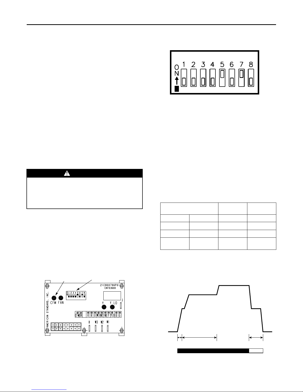
Blower speed changes are made on the ECM Fan
Control. The ECM Fan Control controls the variable
speed motor.
There is a bank of 8 dip switches. The dip switches
work in pairs to match the airflow for the outdoor
unit size (tons). cooling airflow adjustment, Fan offdelay options, and heating airflow adjustment. The
switches appear as shown in Figure 2, p. 6
Figure 1. ECM Fan Control
Figure 2. Dip Switches
If the airflow needs to be increased or decreased,
see the Airflow Label on the air handler or Blower
Performance Table.
Be sure to set the correct airflow for cooling and
heating.
Switches 1–4 Cooling Airflow
Switches 5–6 Fan Off Delay Options
Switches 7–8 Auxiliary Heat
IInnddoooorr BBlloowweerr TTiimmiinngg
IIMMPPOORRTTAANNTT:: Leave dip switches 5 and 6 in the “as-
shipped” positions during system startup and check out. Afterwards, adjust as
desired.
Table 3. Cooling Off — Delay Options
SWITCH SETTINGS SELECTION NOMINAL
5 — OFF 6 — OFF NONE SAME
5 — ON 6 — OFF 1.5 MINUTES 100%
5 — OFF 6 — ON 3 MINUTES 50%
5 — ON 6 — ON ENHANCED
(a)
Default setting
(b)
This ENHANCED MODE selection provides a ramping up and ramping
down of the blower speed to provide improved comfort, quietness,
and potential energy savings. The graph shows the ramping process.
(b)
AIRFLOW
50–100%
(a)
6
Figure 3. Enhanced Mode
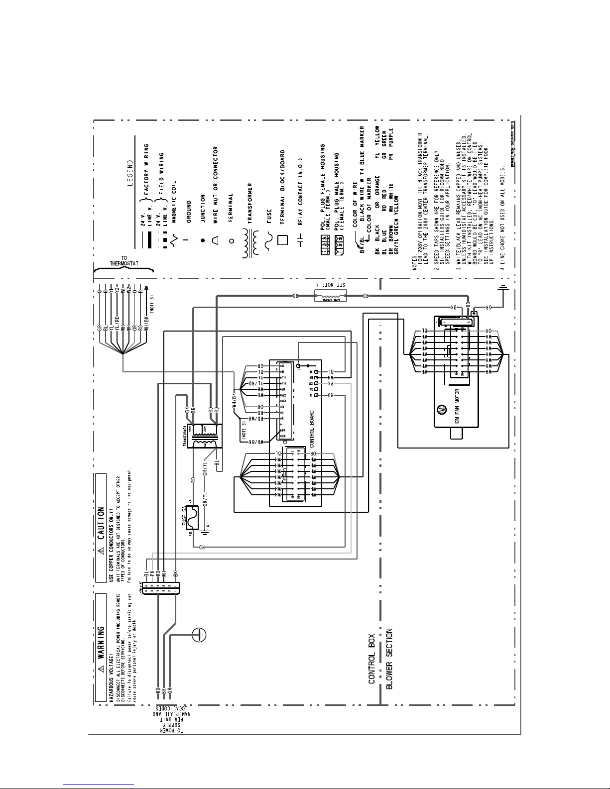
9. WWiirriinngg
18-GF74D1-1F-EN

FFeeaattuurreess
Consult all schematic and pictorial wiring diagrams
of this unit and the outdoor equipment to determine
compatibility of wiring connections and to
determine specific requirements.
All field wiring to the air handler should be installed
in accordance with the latest edition of the National
Electric Code NFPA No. 70 and any local codes.
Check rating plates on unit for rated volts, minimum
circuit ampacity and maximum over current
protection. Supply circuit power wiring must be 75
degree C (167 degree F) minimum copper
conductors only. Copper supply wires shall be sized
to the National Electric Code or local code
requirements, whichever is more stringent.
The unit is shipped wired for 230/240 Volt AC 60 HZ
1 Phase Operation. If the unit is to be operated at
208 VAC 60HZ, follow the instructions on the indoor
unit wiring diagram to change the low voltage
transformer to 208 VAC operation (Ensure unit is
properly grounded).
Class 2 low voltage control wiring should not be run
in conduit with power wiring and must be
separated from power wiring unless class 1 wire
with proper voltage rating is used.
Low voltage control wiring should be 18 Awg, color
coded (105 degree C minimum). For lengths longer
than 100ft., 16 Awg wire should be used. Make
certain that separation of control wiring and power
wiring has been maintained.
10. AAiirr FFiilltteerr
To protect the coil, blower and other internal parts
from excessive dirt and dust an air filter must be
installed before air enters the evaporator coil. A
remote filter must be installed. Consult the filter
manufacturer for proper sizing and maximum
velocity requirements.
IImmppoorrttaanntt:: Air filters shall meet the test requirements
in UL 900.
11. TThheerrmmoossttaatt
Select a thermostat that is commonly used with HP
or AC single stage heating/cooling with electric
heat. The thermostat will energize the fan on a
demand for heat or cool.
Install the thermostat on an inside wall, away from
drafts, lights or other heat sources in a location that
has sufficient air circulation from other rooms being
controlled by the thermostat.
12. SSeeqquueennccee ooff OOppeerraattiioonn
CCoooolliinngg ((CCoooolliinngg oonnllyy))
When the thermostat calls for cooling, the circuit
from R to G is completed. The blower motor is
energized directly by the ECM fan control, which
receives the 24VAC signal from the thermostat.
The circuit from R to Y is also complete energizing
the compressor contactor of the outdoor unit. The
contactor will close and start the compressor and
condenser fan motor.
CCoooolliinngg ((hheeaatt ppuummpp))
When the thermostat calls for cooling, the circuit
from R to G is completed. The blower motor is
energized directly by the ECM fan control, which
receives the 24VAC signal from the thermostat.
The circuit from R to Y is also complete energizing
the compressor contactor of the outdoor unit. The
contactor will close and start the compressor and
condenser fan motor.
Circuit R to O energizes the reversing valve to the
cooling position.
HHeeaattiinngg ((hheeaatt ppuummpp))
When the thermostat calls for heating, the circuit
from R to G is completed and the blower motor is
energized directly by the ECM fan control, which
receives the 24VAC signal from the thermostat.
The circuit from R to Y is also complete energizing
the compressor contactor of the outdoor unit. The
contactor will close and start the compressor and
condenser fan motor.
18-GF74D1-1F-EN
7

FFeeaattuurreess
In the heating mode, the reversing valve of the
outdoor unit is not energized.
If the indoor temperature continues to fall, the R to
W circuit is completed energizing the electric heat
contactor(s).
HHeeaattiinngg ((eelleeccttrriicc hheeaatt oonnllyy))
NNoottee:: The thermostat must be setup to bring the
blower on when the electric heat is energized.
When the thermostat calls for heating, the circuit
from R to G is completed and the blower motor is
energized directly by the ECM fan control, which
receives the 24VAC signal from the thermostat. The
circuit from R to W is completed energizing the
heating contactor(s).
DDeeffrroosstt
Supplemental heat during defrost can be provided
by connecting the X2 (black) wire from the outdoor
unit to W1 or W2 at the indoor unit. This will
prevent cold air from being discharged from the
indoor unit during defrost.
13. OOppeerraattiioonnaall aanndd CChheecckkoouutt PPrroocceedduurreess
To obtain proper performance, all units must be
operated and charge adjustments made in
accordance with procedures found in the Service
Facts document of the outdoor unit. After
installation has been completed, it is recommended
that the entire system be checked against the
checkout list located at the back of this document.
See “Checkout Procedures,” p. 36
14. MMaaiinntteennaannccee
The system air filter(s) should be inspected, cleaned
or replaced at least monthly. Make certain that the
access panels are replaced and secured properly
before placing the unit back in operation. This
product is designed for dependable service;
however, periodic maintenance should be
scheduled and conducted by trained professional
service personnel. This service should be
conducted at least annually, and should include
testing and inspection of electrical and refrigerant
components. The heat transfer surface should be
cleaned. The blower motor is permanently
lubricated for normal operating conditions.
8
18-GF74D1-1F-EN
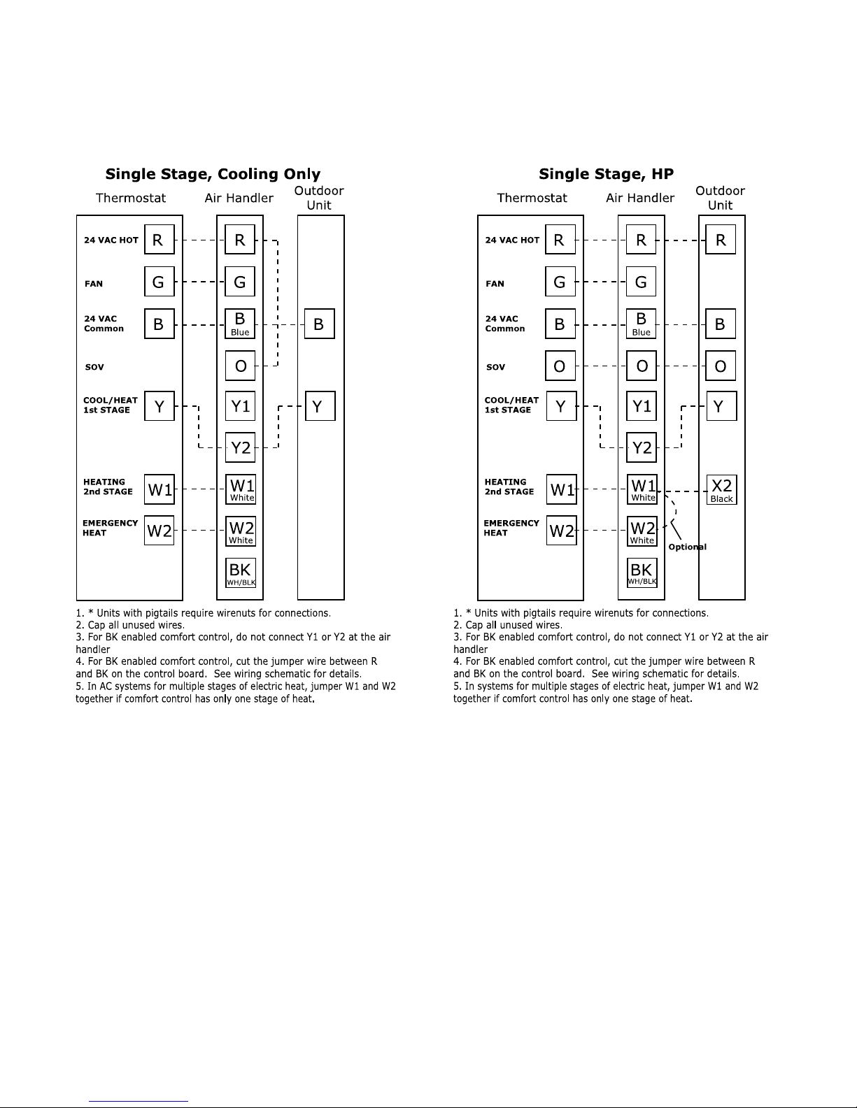
Field Wiring
Sing le St age, C o o lin g On ly
The rm ostat Air H andler
Outdoor
Unit
R
G
B
W1
W2
B
Y
R
G
B
Y
W1
Blue
24 VAC HOT
FAN
24 VAC
Common
SOV
COOL/HEAT
1st STAGE
HEATING
2nd STAGE
EMERGENCY
HEAT
White
White
W2
O
Y1
1. * Uni ts wi th pi gtai ls re quire wirenut s for conn ections.
2. Cap al l unu sed wire s.
3. F or BK ena b led com fort control, do not conn e ct Y1 or Y2 at the air
handl e r
Y2
BK
WH/BLK
4. F or BK ena b led com fort control, cut the jumpe r wire betw een R
and BK on the control board. See wi ring schematic for d e tails.
5. In AC s yst em s for mult iple s tages of e lectric heat , jumper W1 a n d W2
tog ether if c o m fort control h as o nly one sta g e of heat.
Sing le St age, HP
The rm ostat Air H andler
Outdoor
Unit
R
G
B
W1
W2
R
B
O
Y
X2
R
G
B
O
Y
W1
Blue
24 VAC HOT
FAN
24 VAC
Common
SOV
COOL/HEAT
1st STAGE
HEATING
2nd STAGE
EMERGENCY
HEAT
White
Black
White
W2
O
Y1
Y2
BK
Optional
WH/BLK
1. * Uni ts wi th pi gtai ls re quire wirenut s for conn ections.
2. Cap al l unu sed wire s.
3. F or BK ena b led com fort control, do not conn e ct Y1 or Y2 at the air
handl e r
4. F or BK ena b led com fort control, cut the jumpe r wire betw een R
and BK on the control board. See wi ring schematic for d e tails.
5. In s ystem s fo r m u ltiple stage s of electric he a t, jum per W1 a n d W2
tog ether if c o m fort control h as o nly one sta g e of heat.
18-GF74D1-1F-EN
9
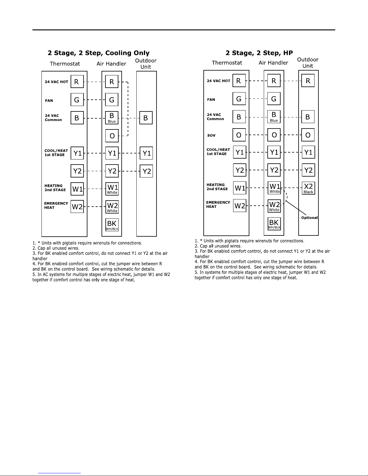
2 St age, 2 Step, Coo lin g O n ly
The rm o
stat
Air H andler
Outdoor
Unit
R
G
B
W1
W2
B
Y1
R
G
B
Y1
W1
Blue
24 VAC HOT
FAN
24 VAC
Common
COOL/HEAT
1st STAGE
HEATING
2nd STAGE
EMERGENCY
HEAT
White
White
W2
O
Y1
Y2
BK
Y2
Y2
WH/BLK
1. * Uni ts wi th pi gtai ls re quire wirenut s for conn ections.
2. Cap al l unu sed wire s.
3. F or BK ena b led com fort control, do not conn e ct Y1 or Y2 at the air
handl e r
4. F or BK ena b led com fort control, cut the jumpe r wire betw een R
and BK on the control board. See wi ring schematic for d e tails.
5. In AC s yst em s for mult iple s tages of e lectric heat , jumper W1 a n d W2
tog ether if c o m fort control h as o nly one sta g e of heat.
2 St age, 2 Step, HP
The rm ostat Air H andler
Outdoor
Unit
R
G
B
W1
W2
R
B
O
Y1
X2
R
G
B
O
Y1
W1
Blue
24 VAC HOT
FAN
24 VAC
Common
SOV
COOL/HEAT
1st STAGE
HEATING
2nd STAGE
EMERGENCY
HEAT
White
Black
White
W2
O
Y1
Y2
BK
Optional
Y2Y2
WH/BLK
1. * Uni ts wi th pi gtai ls re quire wirenut s for conn ections.
2. Cap al l unu sed wire s.
3. F or BK ena b led com fort control, do not conn e ct Y1 or Y2 at the air
handl e r
4. F or BK ena b led com fort control, cut the jumpe r wire betw een R
and BK on the control board. See wi ring schematic for d e tails.
5. In s ystem s fo r m u ltiple stage s of electric he a t, jum per W1 a n d W2
tog ether if c o m fort control h as o nly one sta g e of heat.
FFiieelldd WWiirriinngg
10
18-GF74D1-1F-EN
Electrical Data
18-GF74D1-1F-EN
11
 Loading...