

Ingersoll-Rand TAM7A0C36H31EA, TAM7A0C48H41EA, TAM7A0C42H31EA, TAM7A0B30H21EA, TAM7B0C60H51EA Installer Manual
...
Installer’s Guide
Air Handlers
Convertible 2 — 5 Ton
BBllaacckk EEppooxxyy CCooiillss
TAM7A0A24H21EA
TAM7A0B30H21EA
TAM7A0C36H31EA
TAM7A0C42H31EA
TAM7A0C48H41EA
TAM7B0C60H51EA
SSttaannddaarrdd CCooiillss
TAM7A0A24H21SD
TAM7A0B30H21SD
TAM7A0C36H31SD
TAM7A0C42H31SD
TAM7A0C48H41SD
TAM7B0C60H51SC
Scan or click to view
TAM7 Trouble Shooting
Video Library
Only qualified personnel should install and service the equipment. The installation, starting up, and servicing of heating, ventilating, and
air-conditioning equipment can be hazardous and requires specific knowledge and training. Improperly installed, adjusted or altered
equipment by an unqualified person could result in death or serious injury. When working on the equipment, observe all precautions in the
literature and on the tags, stickers, and labels that are attached to the equipment.
July 2014
NNoottee:: “Graphics in this document are for representation only.
Actual model may differ in appearance.”
NNoottee:: For use with BAYEV or BAYW series heaters ONLY
SSAAFFEETTYY WWAARRNNIINNGG
18-GJ06D2-2E-EN
SAFETY SECTION
AIR HANDLERS
IImmppoorrttaanntt — This document contains a wiring
diagram, a parts list, and service information. This is
customer property and is to remain with this unit.
Please return to service information pack upon
completion of work.
WWAARRNNIINNGG
HHAAZZAARRDDOOUUSS VVOOLLTTAAGGEE!!
FFaaiilluurree ttoo ffoollllooww tthhiiss WWaarrnniinngg ccoouulldd rreessuulltt iinn
pprrooppeerrttyy ddaammaaggee,, sseevveerree ppeerrssoonnaall iinnjjuurryy,, oorr ddeeaatthh..
DDiissccoonnnneecctt aallll eelleeccttrriicc ppoowweerr,, iinncclluuddiinngg rreemmoottee
ddiissccoonnnneeccttss bbeeffoorree sseerrvviicciinngg.. FFoollllooww pprrooppeerr
lloocckkoouutt//ttaaggoouutt pprroocceedduurreess ttoo eennssuurree tthhee ppoowweerr
ccaannnnoott bbee iinnaaddvveerrtteennttllyy eenneerrggiizzeedd..
CCAAUUTTIIOONN
GGRROOUUNNDDIINNGG RREEQQUUIIRREEDD!!
FFaaiilluurree ttoo iinnssppeecctt oorr uussee pprrooppeerr sseerrvviiccee ttoooollss mmaayy
rreessuulltt iinn eeqquuiippmmeenntt ddaammaaggee oorr ppeerrssoonnaall iinnjjuurryy..
RReeccoonnnneecctt aallll ggrroouunnddiinngg ddeevviicceess.. AAllll ppaarrttss ooff tthhiiss
pprroodduucctt tthhaatt aarree ccaappaabbllee ooff ccoonndduuccttiinngg eelleeccttrriiccaall
ccuurrrreenntt aarree ggrroouunnddeedd.. IIff ggrroouunnddiinngg wwiirreess,, ssccrreewwss,,
ssttrraappss,, cclliippss,, nnuuttss,, oorr wwaasshheerrss uusseedd ttoo ccoommpplleettee aa
ppaatthh ttoo ggrroouunndd aarree rreemmoovveedd ffoorr sseerrvviiccee,, tthheeyy mmuusstt
bbee rreettuurrnneedd ttoo tthheeiirr oorriiggiinnaall ppoossiittiioonn aanndd pprrooppeerrllyy
ffaasstteenneedd..
WWAARRNNIINNGG
PPRREESSSSUURRIIZZEEDD RREEFFRRIIGGEERRAANNTT!!
FFaaiilluurree ttoo ffoollllooww tthhiiss WWaarrnniinngg ccoouulldd rreessuulltt iinn
ppeerrssoonnaall iinnjjuurryy
SSyysstteemm ccoonnttaaiinnss ooiill aanndd rreeffrriiggeerraanntt uunnddeerr hhiigghh
pprreessssuurree.. RReeccoovveerr rreeffrriiggeerraanntt ttoo rreelliieevvee pprreessssuurree
bbeeffoorree ooppeenniinngg tthhee ssyysstteemm.. DDoo nnoo uussee nnoonn-aapppprroovveedd rreeffrriiggeerraannttss oorr rreeffrriiggeerraanntt ssuubbssttiittuutteess oorr
rreeffrriiggeerraanntt aaddddiittiivveess..
CCAAUUTTIIOONN
SSHHAARRPP EEDDGGEE HHAAZZAARRDD!!
FFaaiilluurree ttoo ffoollllooww tthhiiss CCaauuttiioonn ccoouulldd rreessuulltt iinn
pprrooppeerrttyy ddaammaaggee oorr ppeerrssoonnaall iinnjjuurryy..
BBee ccaarreeffuull ooff sshhaarrpp eeddggeess oonn eeqquuiippmmeenntt oorr aannyy
ccuuttss mmaaddee oonn sshheeeett mmeettaall wwhhiillee iinnssttaalllliinngg oorr
sseerrvviicciinngg..
IImmppoorrttaanntt:: Panel damage can occur with prolonged
exposure to POE lubricants. Air handler
front panels that come in contact with POE
oil must be washed immediately with
soapy water.
NNoottee:: Representative illustrations only included in this
document. Most illustrations display the upflow
configuration.
WWAARRNNIINNGG
LLIIVVEE EELLEECCTTRRIICCAALL CCOOMMPPOONNEENNTTSS!!
FFaaiilluurree ttoo ffoollllooww tthhiiss WWaarrnniinngg ccoouulldd rreessuulltt iinn
pprrooppeerrttyy ddaammaaggee,, sseevveerree ppeerrssoonnaall iinnjjuurryy,, oorr ddeeaatthh..
FFoollllooww aallll eelleeccttrriiccaall ssaaffeettyy pprreeccaauuttiioonnss wwhheenn
eexxppoosseedd ttoo lliivvee eelleeccttrriiccaall ccoommppoonneennttss.. IItt mmaayy bbee
nneecceessssaarryy ttoo wwoorrkk wwiitthh lliivvee eelleeccttrriiccaall ccoommppoonneennttss
dduurriinngg iinnssttaallllaattiioonn,, tteessttiinngg,, sseerrvviicciinngg,, aanndd
ttrroouubblleesshhoooottiinngg ooff tthhiiss pprroodduucctt..
©2014 Trane
18-GJ06D2-2E-EN

Table of Contents
Installer Guide Notes . . . . . . . . . . . . . . . . . . . . . . . 4
Unit Design. . . . . . . . . . . . . . . . . . . . . . . . . . . . . . . . . 5
Unit Install Preparation . . . . . . . . . . . . . . . . . . . . . 7
Optional Equipment . . . . . . . . . . . . . . . . . . . . . . . . 8
Optional Cabinet Disassembly. . . . . . . . . . . . . . 9
Placing Unit at Location . . . . . . . . . . . . . . . . . . . 13
Unit Location Considerations. . . . . . . . . . . . . . 14
Four-Way Conversion. . . . . . . . . . . . . . . . . . . . . . 15
Ducted and Non-Ducted
Applications . . . . . . . . . . . . . . . . . . . . . . . . . . . . . . . 17
Additional Unit Preparation
Considerations . . . . . . . . . . . . . . . . . . . . . . . . . . . . 18
Setting the Unit — Vertical
Installation . . . . . . . . . . . . . . . . . . . . . . . . . . . . . . . . 19
Setting the Unit — Horizontal
Installations . . . . . . . . . . . . . . . . . . . . . . . . . . . . . . . 22
Connecting the Duct work . . . . . . . . . . . . . . . . . 23
Refrigerant Line . . . . . . . . . . . . . . . . . . . . . . . . . . . 24
Refrigerant System Layout . . . . . . . . . . . . . . . 24
Refrigerant Line Brazing . . . . . . . . . . . . . . . . . . . 25
Condensate Drain Piping . . . . . . . . . . . . . . . . . . 29
Electrical — Low Voltage . . . . . . . . . . . . . . . . . . 32
Dip Switches . . . . . . . . . . . . . . . . . . . . . . . . . . . . . . 39
Indoor Blower Options . . . . . . . . . . . . . . . . . . . . 41
Control Plate Reinstall . . . . . . . . . . . . . . . . . . . . . 42
Electrical — High Voltage . . . . . . . . . . . . . . . . . . 43
TAM7 OUTLINE DRAWING . . . . . . . . . . . . . . . . 46
Filters . . . . . . . . . . . . . . . . . . . . . . . . . . . . . . . . . . . . . 47
System Charge Adjustments . . . . . . . . . . . . . 47
System Start Up . . . . . . . . . . . . . . . . . . . . . . . . . . . 48
TAM7 Sequence of Operation . . .. . . . . . . . . . 49
Abbreviations . . . . . . . . . . . . . . . . . . . . . . . . . . . 49
Checkout Procedures . . . . . . . . . . . . . . . . . . . . . . 51
18-GJ06D2-2E-EN
3
Installer Guide Notes
AALLLL PPhhaasseess ooff tthhiiss iinnssttaallllaattiioonn mmuusstt ccoommppllyy wwiitthh
NNAATTIIOONNAALL,, SSTTAATTEE aanndd LLOOCCAALL CCOODDEESS!!
IImmppoorrttaanntt:: This Document is customer property and is
to remain with t his unit. Please return to
service information upon completion of
work
IImmppoorrttaanntt:: These instructions do not cover all
variations in systems nor provide for every
possible contingency to be met in
connection with the installation. Should
further information be desired or should
particular problems arise which are not
covered sufficiently for the purchaser’s
purposes, the matter should be referred to
your installing dealer or local distributor.
SSeeee TTAAMM77 SSeerrvviiccee FFaaccttss ddooccuummeenntt ffoorr iinnffoorrmmaattiioonn
oonn rreeaaddiinngg tthhee CCoonnttrrooll BBooaarrdd LLEEDDss,, AAiirr FFllooww TTaabblleess
aanndd TTrroouubblleesshhoooottiinngg FFlloowwcchhaarrttss..
NNoottee:: The manufacturer recommends installing ONLY
A.H.R.I. approved, matched indoor and outdoor
systems. Some of the benefits of installing
approved matched indoor and outdoor split
systems are maximum efficiency, optimum
performance, and the best overall system
reliability.
NNoottee:: Condensation may occur on the surface of the air
handler when installed in unconditioned spaces,
verify that all electrical and refrigerant line
penetrations on the air handler are sealed
completely.
The TAM7 air handlers will only use the following
internal electric heaters:
BAYEVAC04BK1AA BAYEVAC10LG1AA
BAYEVAC04LG1AA BAYEVBC15BK1AA
BAYEVAC05BK1AA BAYEVBC20BK1AA
BAYEVAC05LG1AA BAYEVCC25BK1AA
BAYEVAC08BK1AA BAYEVAC10LG3AA
BAYEVAC08LG1AA BAYEVBC15LG3AA
BAYEVAC10BK1AA
NNoottee:: Duct heaters cannot be applied with this air
handler.
4
18-GJ06D2-2E-EN
Unit Design
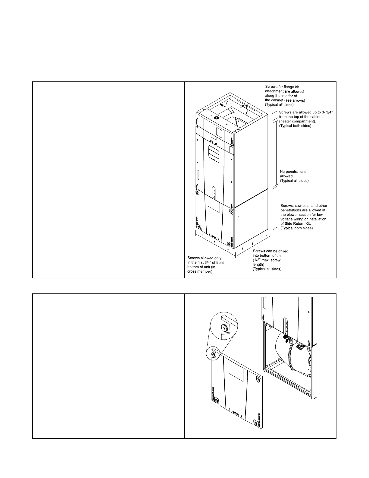
Screws ca n be drilled
into bottom of unit.
(1/2” max. s crew
length)
(Typical all sides)
Screws , saw cuts, and other
penetrations are a llowed in
the blower se ction for low
voltage wiring or installat
io
n
of Side Return Kit.
(Typical both sides)
Screws are a llowed up to 3- 3/4”
from the top of the ca bine t
(heate r compartment).
(Typical both sides)
Screws for flange kit
attachment are allowe
d
along the inte rior of
the cabinet (se e arrows )
(Typical all sides)
No penetrations
allowe d.
(Typical all sides)
Screws allowe d only
in the first 3/4” of front
bottom of unit (in
cross member)
Table 1. Cabinet Penetration
Important: Due to the unique design of this unit, which allows the
electrical wiring to be routed within the insulation, do not
screw, cut, or otherwise puncture the unit cabinet in any
location other than the ones illustrated.
Important: Under no conditions should metal strapping be attached
to the unit to be used as support mechanisms for
carrying or suspension purposes.
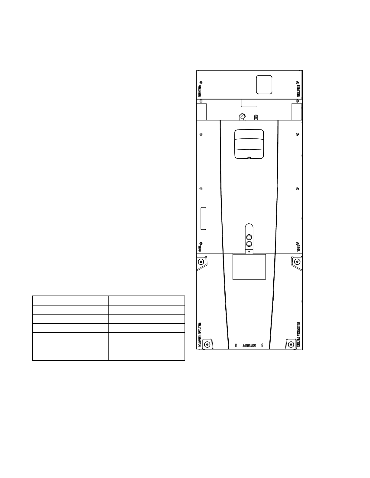
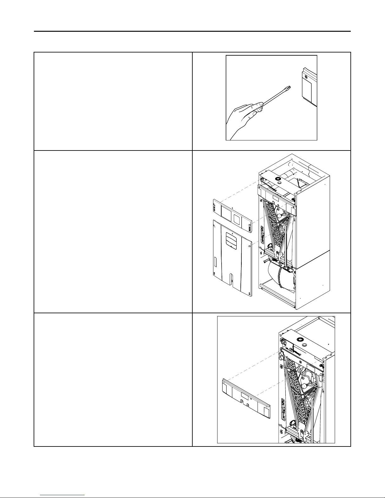
Table 2. Panel Removal
The unit contains four (4) access panels: Blower/Filter, Coil, Line Set,
and Heater.
The Blower/Filter panel is removed using 1/4 turn thumb screws.
1. Turn thumb screws on Blower/Filter panel.
2. Pull top of panel out, away from cabinet.
3. Lift panel up out of channel.
4. Set aside.
18-GJ06D2-2E-EN
5
0
0
0
0
UUnniitt DDeessiiggnn
The Coil, Line Set, and Heater panels are removed using Phillips head
screws.
Removal requires #3 Size Phillips
Coil and Heater panels must be removed prior to removing the Line
Set panel.
To remove Coil Panel:
1. Turn screws on Coil panel.
2. Pull bottom of panel out, away from cabinet.
3. Pull panel down and out of channel.
4. Set aside.
To remove Heater Panel:
1. Turn screws on Heater panel.
2. Pull panel straight out, away from cabinet.
3. Set aside.
Removal of the Line Set panel is required for all refrigerant line brazing
and some condensate line assembly depending on your orientation.
To remove Line Set panel:
1. Remove both Heater and Coil panels.
2. Turn screws on Line Set panel.
3. Pull panel straight out, away from cabinet.
4. Set aside.
Note: After replacing all panels, loosen the Line Set panel screws
approximately 1/4 — 1/2 turn. This will improve the seal
between the Heater Panel and Line Set panel.
6
18-GJ06D2-2E-EN
Unit Install Preparation
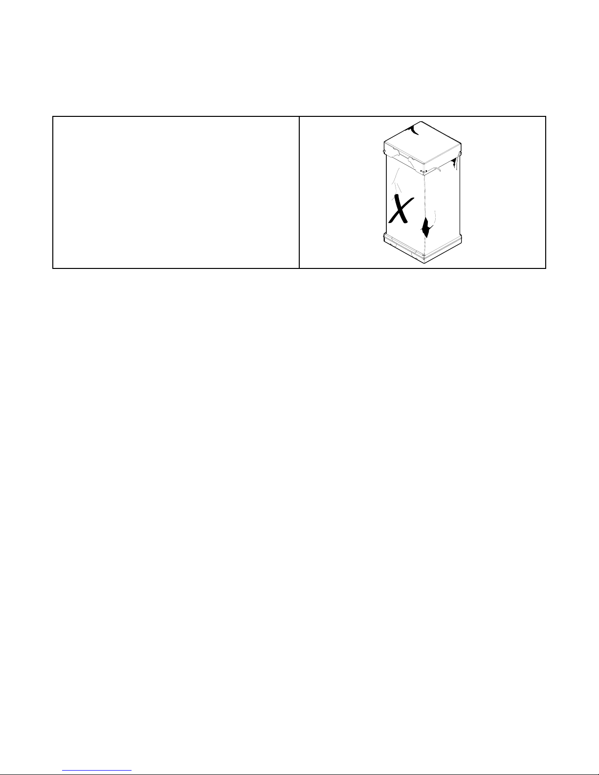
1. Check for damage and report promptly to the carrier any damage
found to the unit.
Note: If the unit must be transported in a horizontal position, it must
be laid on its back (marked “REAR” on carton).
Note: After unit is removed from the carton, verify coil is pressurized.
Carefully remove the liquid line plug. If no pressure is released,
check for leaks.
Note: Remove the cardboard from the bottom of the blower. Cut the
tie wrap and remove the foam shipping block located at the
motor.
18-GJ06D2-2E-EN
7
Optional Equipment
Accessory Number Description
BAYEVAC04BK1AA
BAYEVAC04LG1AA
BAYEVAC05BK1AA
BAYEVAC05LG1AA
BAYEVAC08BK1AA
BAYEVAC08LG1AA
BAYEVAC10BK1AA
BAYEVAC10LG1AA
BAYEVBC15BK1AA
BAYEVBC20BK1AA
BAYEVCC25BK1AA
BAYEVAC10LG3AA
BAYEVBC15LG3AA
BAYSUPFLGAA
BAYSUPFLGBA
BAYSUPFLGCA
BAYRETFLGAA
BAYRETFLGBA
BAYRETFLGCA
BAYSRKIT100A Side Return Kit A to C
BAYFLR1620A
BAYFLR2020A
BAYFLR2220A
TASB175SB
TASB215SB
TASB235SB
MITISRKIT01A Side Return Kit with 16” x 20” Filter A to C
BAYFRKIT175 Front Return Kit for 17.5” Cabinet A
BAYFRKIT210 Front Return Kit for 21.0” Cabinet B
BAYFRKIT235 Front Return Kit for 23.5” Cabinet C
BAYBAFKT175A Sound Baffle Kit for 17.5” Cabinet A
BAYBAFKT215A Sound Baffle Kit for 21.0” Cabinet B
BAYBAFKT235A Sound Baffle Kit for 23.5” Cabinet C
TASSBK175 Sound Baffle Kit for 17.5” Cabinet A
TASSBK210 Sound Baffle Kit for 21.0” Cabinet B
TASSBK235 Sound Baffle Kit for 23.5” Cabinet C
BAYICSKIT01A Internal Condensate Switch Kit A to C
BAYHHKIT001A
BAYUVCLK001A
BAYLVKIT100A
BAYSPEKT200A
BAYWVAA05SC1AA
BAYWVBB07SC1AA
BAYWVCC08SC1AA
BAYWACC11SC1AA
BAYWVBRD485A RS-485 Control for BAYWACC11SC1AA C to C
BAYINSKT175A
BAYINSKT215A
BAYINSKT235A
BAYCNDPIP01A
Electric Heater, 4kW, Breaker, RS-485 Control, 1 Ph
Electric Heater, 4kW, Lugs, RS-485 Control, 1 Ph
Electric Heater, 5kW, Breaker, RS-485 Control, 1 Ph
Electric Heater, 5kW, Lugs, RS-485 Control, 1 Ph
Electric Heater, 8kW, Breaker, RS-485 Control, 1 Ph
Electric Heater, 8kW, Lugs, RS-485 Control, 1 Ph
Electric Heater, 10kW, Breaker, RS-485 Control, 1 Ph
Electric Heater, 10kW, Lugs, RS-485 Control, 1 Ph
Electric Heater, 15kW, Breaker, RS-485 Control, 1 Ph
Electric Heater, 20kW, Breaker, RS-485 Control, 1 Ph
Electric Heater, 25kW, Breaker, RS-485 Control, 1 Ph
Electric Heater, 10kW, Lugs, RS-485 Control, 3 Ph
Electric Heater, 15kW, Lugs, RS-485 Control, 3 Ph
Supply Duct Flange A
Supply Duct Flange B
Supply Duct Flange C
Return Duct Flange A
Return Duct Flange B
Return Duct Flange C
High Velocity Filter Kit, 16” x 20” x 1” (10 filters)
High Velocity Filter Kit, 20” x 20” x 1” (10 filters)
High Velocity Filter Kit, 22” x 20” x 1” (10 filters)
Plenum Stand with integrated sound baffle A
Plenum Stand with integrated sound baffle B
Plenum Stand with integrated sound baffle C
Horizontal Hanger Kit
UVC Lights
Low Voltage Conduit Entry Kit
Single Power Entry Kit
Hydronic Coil — 50,000 BTUH — Slide-in with control
Hydronic Coil — 70,000 BTUH — Slide-in with control
Hydronic Coil — 80,000 BTUH — Slide-in with control
Hydronic Coil — 100,000 BTUH — Add on
Solcoustic® Liner Kit for 17.5” cabinet
Solcoustic® Liner Kit for 21.5” cabinet
Solcoustic® Liner Kit for 23.5” cabinet
3/4” PVC Threaded Pipe Kit foam Seal (10 per box)
A to C
A to C
A to C
A to C
A to C
A to C
A to C
A to C
B to C
C
C
A to C
B to C
A
B
C
A
B
C
A
B
C
A
B
C
A to C
A to C
A to C
A to C
A to A
B to B
C to C
C to C
A
B
C
A to C
Fits Cabinet Size
8
18-GJ06D2-2E-EN
Optional Cabinet Disassembly
Note: If the unit must be transported in a horizontal position, it must be
laid on its back (marked “REAR” on carton).
Note: To reassemble cabinet, follow the steps in reverse order. Ensure
electrical connections are secure and the plug clips are engaged.
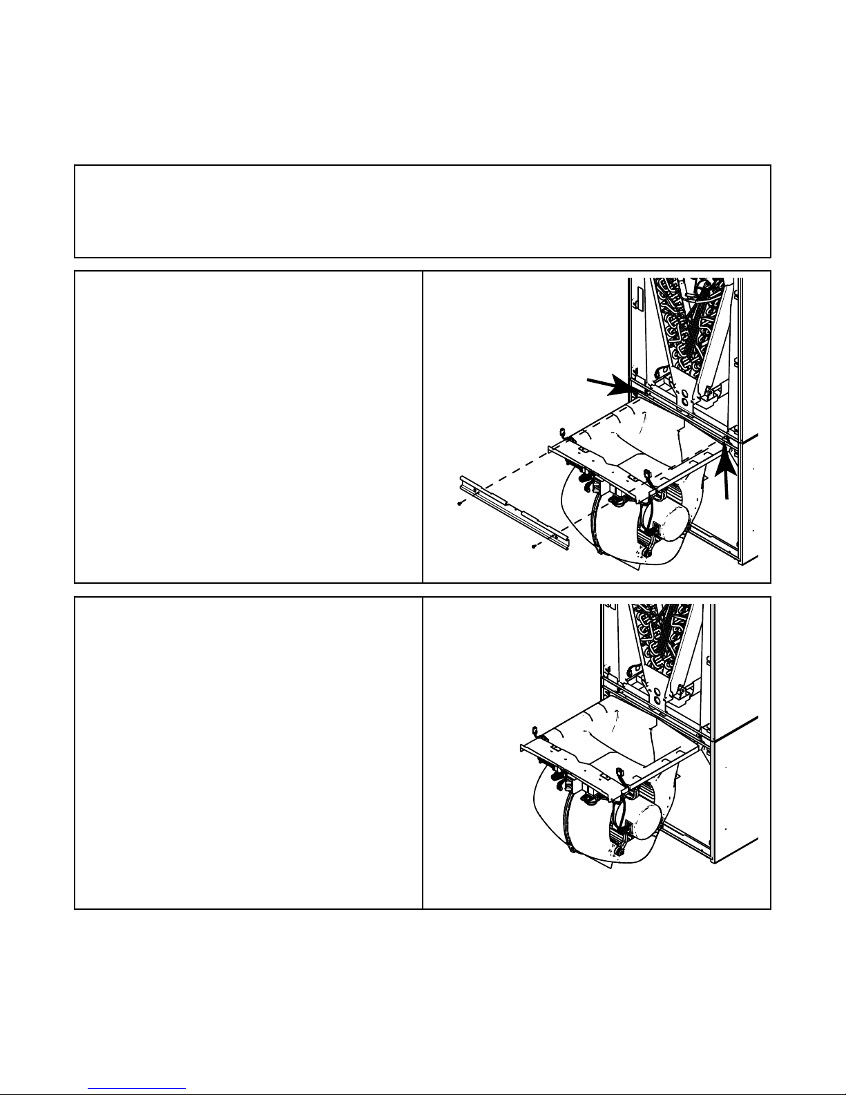
1. Remove all four front panels.
2. Remove the two screws on the seal bar and pull the seal bar
straight out.
3. Disconnect all wiring connections routed to the blower assembly.
See Table 2, p. 5
4. Slide Blower assembly out of unit using built-in blower support
channels and set aside.
Note: Remove the cardboard from the bottom of the blower. Cut the
tie wrap and remove the foam block located at the motor.
18-GJ06D2-2E-EN
9
Coil Support
Channel
OOppttiioonnaall CCaabbiinneett DDiissaasssseemmbbllyy
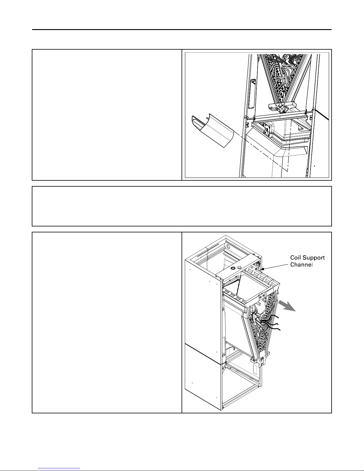
5. Remove airflow diverter from the bottom of coil drain pan by
gripping the plastic diverter while using your thumbs to spread
the top of the diverter slightly outwards and then pulling down
and out through the blower opening as illustrated.
6. Disconnect wires to the EEV motor and sensors. Cut the wire ties on
those wire harnesses if necessary and replace after re-installing.
Note: If cut, wire ties that held the sensor must be replaced after the coil is
placed back into the cabinet.
7. Slide Coil assembly out of unit using built-in coil support channels
and set aside
10
18-GJ06D2-2E-EN
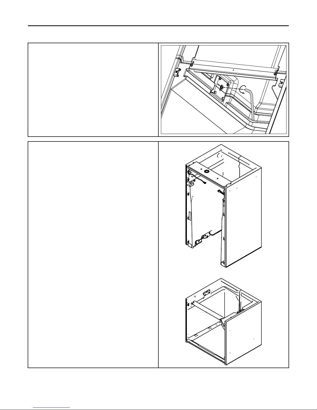
8. Use a 5/16 Allen wrench on the locking mechanism on each side
of the bottom half of the cabinet to loosen the locking mechanism.
The locks loosen by turning counter-clockwise approximately 3/4
of a turn.
9. Lift the Coil section up and away from the Blower section. Set
aside.
Note: When separating the two cabinet pieces, make sure the gasket
remains intact.
OOppttiioonnaall CCaabbiinneett DDiissaasssseemmbbllyy
18-GJ06D2-2E-EN
11
OOppttiioonnaall CCaabbiinneett DDiissaasssseemmbbllyy
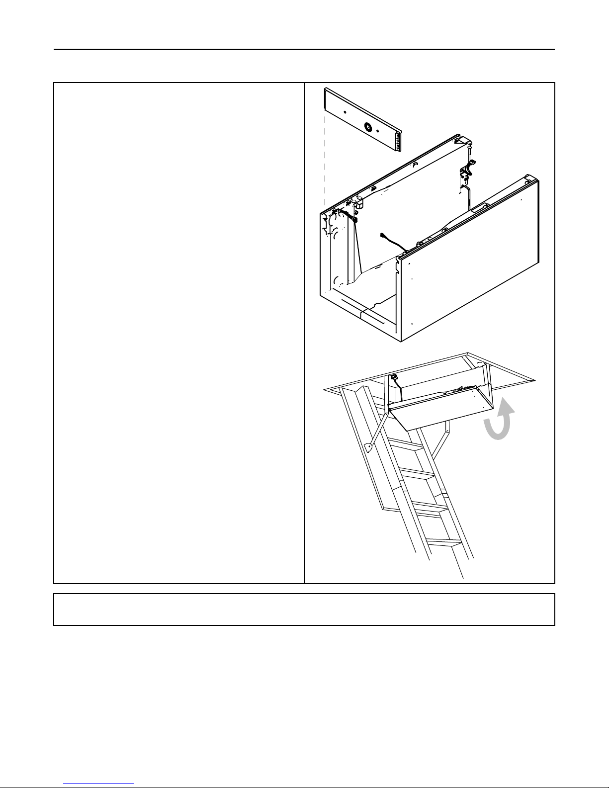
10. For extremely tight spaces where the cabinet needs to be rotated
through a small opening, remove the top panel and all cross
members. Use a manual driver to avoid stripping screw holes.
11. Continue preparation by following the proper carrying procedures shown in the next section.
12
18-GJ06D2-2E-EN
Placing Unit at Location
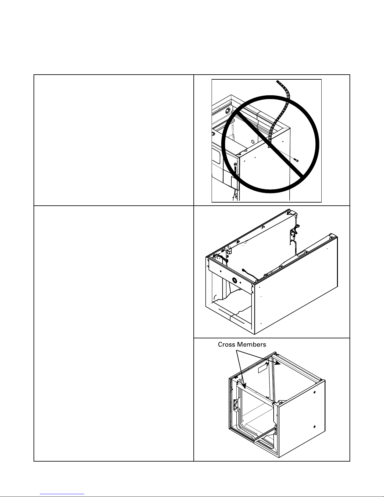
Cross M em bers
1. Carry the unit to the installation location
2. Reassembly by reversing the steps listed in Section 4 if
disassembly was required. If cut, wire ties that held the sensor
wiring must be replaced.
Important: Under no conditions should metal strapping be attached
Approved Carrying:
• Hold by the cross members within the cabinet or unit top plate and
to the unit to be used as support mechanisms for carrying
or suspension purposes.
use as handles for lifting and carrying the coil and blower sections.
18-GJ06D2-2E-EN
13
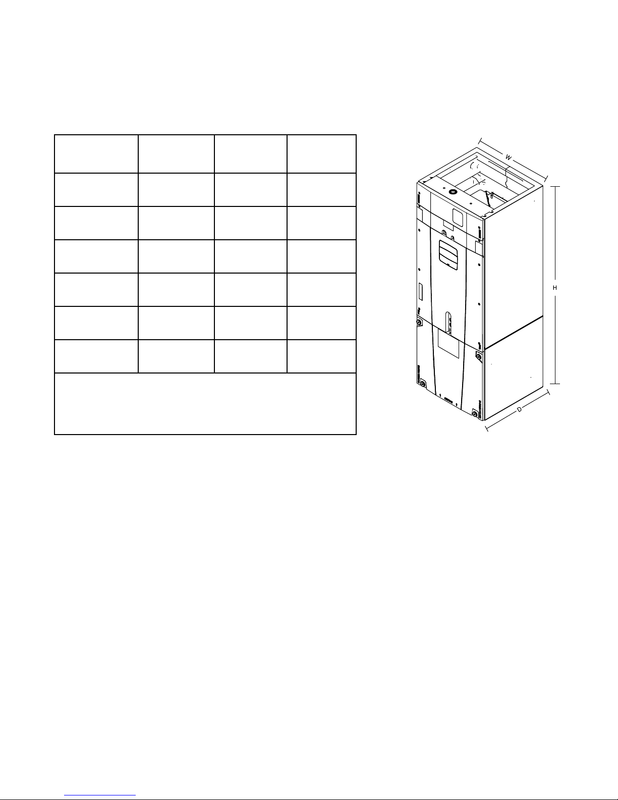
Unit Location Considerations
D
H
W
Table 3. Unit Dimensions and Weight
Coil and Heater
Compartment
Height *
(inches)
Unit Net Weight
(pounds)
MODEL NUMBER
H x W x D
(inches)
TAM7A0A24H21SD
TAM7A0A24H21EA
TAM7A0B30H21SD
TAM7A0B30H21EA
TAM7A0C36H31SD
TAM7A0C36H31EA
TAM7A0C42H31SD
TAM7A0C42H31EA
TAM7A0C48H41SD
TAM7A0C48H41EA
TAM7B0C60H51SC
TAM7B0C60H51EA
* Blower compartment height is 21.8 inches.
49.9 x 17.5 x 21.8 28.1 120
55.7 x 21.3 x 21.8 33.9 133
56.9 x 23.5 x 21.8 35.1 143
56.9 x 23.5 x 21.8 35.1 158
61.7 x 23.5 x 21.8 39.9 174
61.7 x 23.5 x 21.8 39.9 178
14
18-GJ06D2-2E-EN
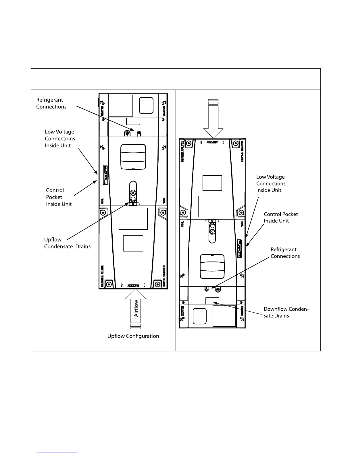
Air ow
Up ow Con guration
Refrigerant
Connections
Low Voltage
Connections
Inside Unit
Control
Pocket
Inside Unit
Upo w
Condensate Drains
Low Voltage
Connections
Inside Unit
Control Pocket
Inside Unit
Refrigerant
Connections
Down ow Conden-
sate Drains
Four-Way Conversion
To place the unit in the configuration your application requires (upflow, downflow, horizontal right, or horizontal left), simply turn the unit to
that orientation. Remember to adjust the badge accordingly.
Note: The air handlers are shipped from the factory suitable for four-way application.
18-GJ06D2-2E-EN
15
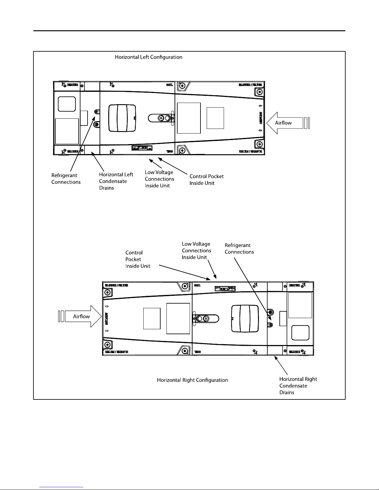
Air ow
Refrigerant
Connections
Horizontal Left
Condensate
Drains
Low Voltage
Connections
Inside Unit
Control Pocket
Inside Unit
Horizontal Left Con guration
Horizontal Right Con guration
Air ow
Control
Pocket
Inside Unit
Low Voltage
Connections
Inside Unit
Refrigerant
Connections
Horizontal Right
Condensate
Drains
FFoouurr--WWaayy CCoonnvveerrssiioonn
16
18-GJ06D2-2E-EN
 Loading...