

Page 1

Before installing or starting this unit for the first
time, this manual should be studied carefully to
obtain a working knowledge of the unit and/or the
duties to be performed while operating and
maintaining the unit.
RETAIN THIS MANUAL WITH UNIT. This
Technical manual contains IMPORTANT
SAFETY DATA and should be kept with the unit
at all times.
More Than Air, Answers.
Online answers: http://www.air.irco.com
Ingersoll Rand
System Automation
VSD V Box
Operator’s Manual
C.C.N. : 80444136
REV. A
DATE DECEMBER 2008
Page 2
TABLE OF CONTENTS
TABLEOFCONTENTS..................................................2
SECTION1–INTRODUCTION......................................3
SECTION2—SAFETY.................................................3
S
AFETYPRECAUTIONS.......................................................3
NSTALLATION.................................................................3
I
PERATION....................................................................3
O
AINTENANCEANDREPAIR..............................................4
M
SECTION3—COMPRESSORCONNECTIONAND
CONTROL...................................................................5
S
TANDARDCONTROLFEATURESANDFUNCTIONALITY............5
VBOXOPERATION...................................................6
VSD
SECTION4—INSTALLATION......................................7
U
NITLOCATION..............................................................7
OWERSUPPLY...............................................................7
P
NETWORK...........................................................7
RS485
VBOXANDPRESSURESENSORCONNECTIVITY...............8
VSD
RESSURESENSORCONNECTIONS.....................................10
P
ISCHARGE(DELIVERY)PRESSURESENSORINTERCONNECT....10
D
ISCHARGE(DELIVERY)PRESSURESENSORANDINTERNAL
D
PRESSURESENSORINTERCONNECT....................................11
COMPRESSORWITHPRESSURESWITCHREGULATED
VSD
COMPRESSORINTERCONNECT..........................................12
VANDIR‐PCBCOMPRESSORCONNECTIVITY...............13
VSD
COMPRESSORSTATUSMONITORING......................13
IR‐PCB
RESSURESWITCHREGULATIONCONTROL.........................15
P
SECTION5—DISPLAYANDMENUOPERATION........19
OPERATION...............................................................19
SECTION6—COMMISSIONING................................21
C
OMMISSIONINGPROCEDURE..........................................21
HYSICALCHECKS..........................................................21
P
OMPRESSORPRESSURESETPOINTS.................................21
C
VBOXCONFIGURATION..........................................22
VSD
RESSURESETPOINTS....................................................24
P
SECTION7—SYSTEMCONFIGURATION...................25
D
ISPLAYITEMSTRUCTURE...............................................25
CCESSINGTHEX12ICONFIGURATIONSCREENS.................25
A
ENUITEMSANDSETTINGS............................................27
M
SECTION8—DIAGNOSTICS.....................................31
SECTION9—FAULTCODES......................................32
SECTION10—VSDVBOXSTATUSBLOCKDIAGRAM 32
SECTION11—PARTSLIST........................................34
SECTION12—TECHNICALDATA..............................34
SECTION13—WIRINGDIAGRAM............................35
VSD
VBOXSCHEMATIC..................................................35
XPM‐TAC24
XPM‐V
XPM‐PSU24
SCHEMATIC...............................................36
O2(+VDCANALOGOUTPUT)................................36
(24VACTO24VDC)....................................36
SECTION14—COMMISSIONINGFORM...................37
Refer to Section Indicated
Note
Important or Caution, Safety
2
Page 3
SECTION 1 – INTRODUCTION
The VSD V (Voltage) Box is intended to provide a
method of system integration for a VSD (Variable Speed
Drive) air compressor equipped with a Voltage Pressure
Sensor that is not equipped with any accessible means of
remote connectivity (such as the Ingersoll Rand Nirvana).
SECTION 2 — SAFETY
SAFETY PRECAUTIONS
WARNING :
!
WARNING :
WARNING :
!
WARNING :
• Before installing or operating the VSD V Box,
take time to carefully read all the instructions
contained in this manual, all compressor
manuals, and all manuals of any other
peripheral devices that may be installed or
connected to the unit.
• Electricity and compressed air have the
potential to cause severe personal injury or
property damage.
• The operator should use com m on sense and
good working practices while operating and
maintaining this system. All applicable codes
should be strictly adhered to.
• Maintenance must be performed b y adequately
qualified personnel that are equipped with the
proper tools.
INSTALLATION
• Installation work must only be carried out by a
competent person under qualified supervision.
• A fused isolation switch must be fitted between
the main power supply and the VSD V Box.
• The VSD V Box should be mounted in such a
location as to allow operational and
maintenance access without obstruction or
hazard and to allow clear visibility of indicators
at all times.
• If raised platforms are required to provide
access to the VSD V Box, they must not
interfere with normal operation or obstruct
access. Platforms and stairs should be of grid or
plate construction with safety rails on all open
sides.
Risk of Danger
Risk of Electric Shock
Risk of High Pressure
Consult Manual
The VSD V Box will provide the required functionality to
enable system integration and efficient control using the
X8I or X12I Automation System.
.
OPERATION
• The VSD V Box must only be operated by
competent personnel under qualified
supervision.
• Never remove or tamper with safety devices,
guards or insulation materials fitted to the VSD
V Box.
• The VSD V Box must only be operated at the
supply voltage and frequency for which it is
designed.
• When main power is switched on, lethal
voltages are present in the electrical circuits and
extreme caution must be exercised whenever it
is necessary to carry out any work on the unit.
• Do not open access panels or touch electrical
components while voltage is applied unless it is
necessary for measurements, tests or
adjustments. Such work should be carried out
only by a qualified electrician equipped with the
correct tools and wearing appropriate protection
against electrical hazards.
• All air compressors and/or other equipment
connected to the unit should have a warning
sign attached stating “THIS UNIT MAY START
WITHOUT WARNING” next to the display panel.
• If an air compressor and/or other equipment
connected to the unit is to be started remotely,
attach two warning signs to the equipment
stating “THIS UNIT CAN BE STARTED
REMOTELY”. Attach one sign in a prominent
location on the outside of the equipment, and
the other sign inside the equipment control
compartment.
3
Page 4

MAINTENANCE AND REPAIR
• Maintenance, repairs or modifications must onl y
be carried out by competent personnel under
qualified supervision.
• If replacement parts are required, use only
genuine parts from the original equipment
manufacturer, or an alternative approved
source.
• Carry out the following operations before
opening or removing any access panels or
carrying out any work on the VSD V Box:
o Isolate the VSD V Box from the main
electrical power supply. Lock the
isolator in the “OFF” position and
remove the fuses.
o Attach labels to the isolator switch and
to the unit stating “WORK IN
PROGRESS - DO NOT APPLY
VOLTAGE”. Do not switch on electrical
power or attempt to start the VSD V
Box if such a warning label is attached.
• Make sure that all instructions concerning
operation and maintenance are strictly followed
and that the complete unit, with all accessories
and safety devices, is kept in good working
order.
• The accuracy of sensor devices must be
checked on a regular basis. They must be
calibrated when acceptable tolerances are
exceeded. Always ensure any pressure within
the compressed air system is safely vented to
atmosphere before attempting to remove or
install a sensor device.
• The VSD V Box must only be cleaned with a
damp cloth, using mild detergents if necessary.
Avoid the use of any substances containing
corrosive acids or alkalis.
• Do not paint the control faceplate or obscure
any indicators, controls, instructions or warnings
4
Page 5
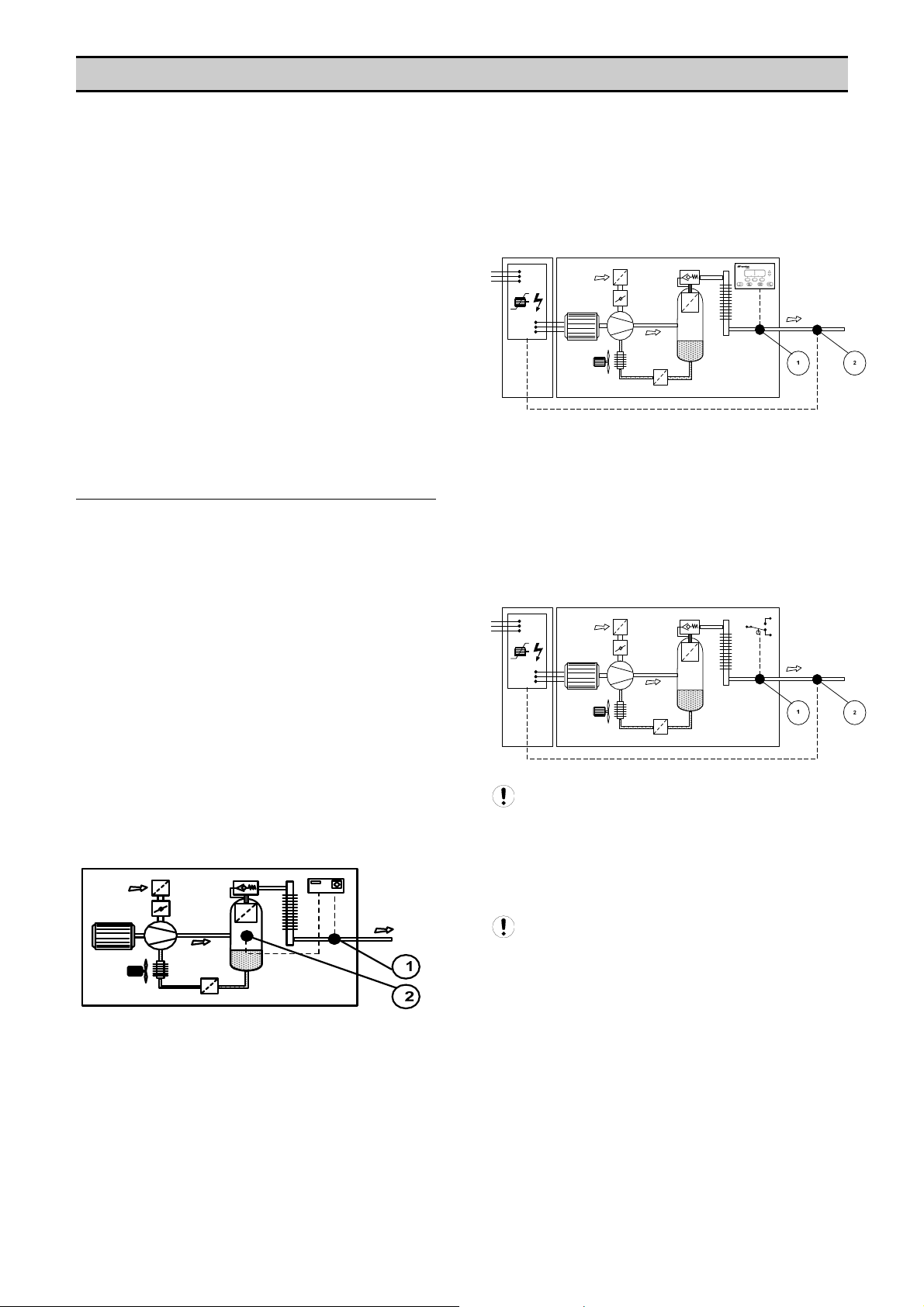
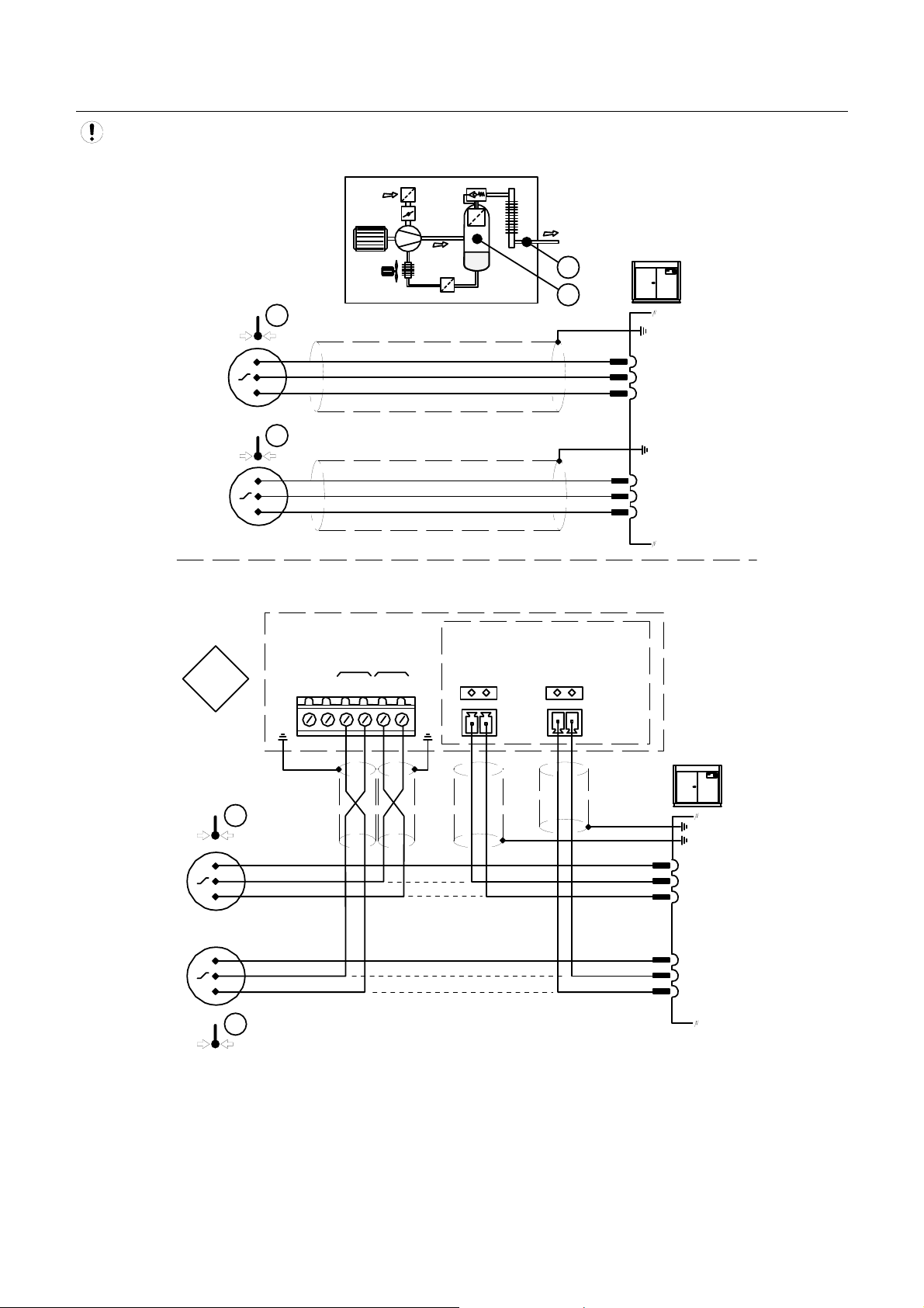
SECTION 3 — COMPRESSOR CONNECTION AND CONTROL
The VSD V (Voltage) Box is designed to connect to an
X8I or X12I Automation System unit, using a 2-wire
RS485 data cable.
The VSD V Box is intended to provide a method of
system integration for 3
not equipped with any accessible means of remote
connectivity. The VSD V Box is used to integrate with
VSD Air Compressors that are controlled by Voltage
Pressure Sensors.
Each air compressor in a system that requires VSD V
Box integration must be equipped with an individual VSD
V Box. Any number of VSD V Boxes can be connected to
the Automation System unit as long as the total number
of compressors does not exceed the total number of
compressors for the Automation System model.
In conjunction with a ‘speed monitoring kit’ (available
separately) the VSD V Box will provide all required
functionality to maximize the ENER, Energy Control
Mode, in the X8I or X12I Automation System.
rd
party air compressors that are
STANDARD CONTROL FEATURES AND
FUNCTIONALITY
The air compressor must be equipped with a 0-5VDC, 15VDC or 0.5-4.5VDC type pressure sensor that is used
for regulation control. For VSD type air compressors; the
compressor must be equipped with a 0-5VDC, 1-5VDC or
0.5-4.5VDC type pressure sensor that is used for variable
speed drive regulation. The VSD V Box will
accommodate a pressure sensor range of 1.0bar to
600bar.
Various Compressor Configurations and Characteristics
Can Be Accommodated by the VSD V Box. These
include::
• Air compressors that are equipped with a package
discharge (delivery) pressure sensor and a second
internal pressure sensor. The internal pressure
sensor is generally used for internal air/oil filtration
differential pressure monitoring and/or internal
pressure safety functions. The VSD V Box is able to
accommodate this requirement without affecting
functionality of the compressor control system
internal pressure sensor feature(s).
• VSD air compressors that are equipped with t wo
pressure sensors that both monitor package
discharge (delivery) pressure. One sensor is
dedicated to compressor control system basic
regulation functions; the other is dedicated to
variable speed drive unit regulation. The VSD V Box
is able to accommodate this requirement without
affecting compressor control system functionality.
• VSD air compressors that are equipped with a
pressure switch dedicated to basic compressor
control system load/unload regulation; and a
pressure sensor dedicated to variable speed drive
unit regulation. The VSD V Box is able to
accommodate pressure switch regulation in
conjunction with variable speed drive pressure
sensor regulation without affecting compressor
control system functionality.
VSD air compressor types that are unable to
maintain maximum speed operation for a prolonged
period of time. In these instances the controller may
automatically reduce speed regardless of demand. The
VSD V Box and management system unit will recognize
this if it occurs and will, if necessary, utilize an additional
compressor to meet demand.
VSD air compressor types are unable to maintain
minimum speed operation for a prolonged period of time.
In these instances the controller may automatically stop
the compressor regardless of demand. The VSD V Box
will recognize and accommodate this behavior. The
management system unit will indicate and record the
compressor status correctly without fault indication.
5
Page 6
VSD V BOX OPERATION
All air compressors are equipped with a method of
sensing pressure. An air compressor regulates using the
compressor package discharge pressure as the control
variable.
The VSD V Box monitors the compressor pressure
sensor as an input and simulates the pressure sensor
signal as an output. The VSD V Box uses this method to
modify the pressure signal and manipulate the behavior
of the air compressor. In other words, the VSD V Box
becomes the air compressor pressure sensor. This
functionality enables the Automation System unit to
utilize the compressor effectively and optimize total
system efficiency and maintain air quality.
The VSD V Box also monitors compressor status (Ready,
Run, and Load/Unload) and continuously reports this
information to the Automation System unit. This function
enables the VSD V Box to simulate all features of a
standard X8I or X12I network compressor integration.
Actual System pressure and the Automation System
‘target’ pressure information is routinely transmitted from
the X8I or X12I to the VSD V Box. The VSD V Box uses
this information to calculate the difference between the
compressor discharge pressure and the system ‘target’
pressure. The VSD V Box utilizes pressure signal
manipulation to continuously re-align compressor output
with system requirements.
This functionality also enables the VSD V Box to
continuously compensate for any pressure differential
that may occur across local air treatment, along air pipe
work or between different locations in a compressed air
network.
VSD V Box Operation Example:
If the Automation System unit is detecting a network air
pressure (PN) of 100psi (6.9bar), and the system target
pressure requirement (P) is 103psi (7.1bar), the VSD V
Box will immediately calculate that a pressure rise of 3psi
(0.2bar) is required to achieve and maintain system
target pressure (P). Due to pressure differential across a
local compressed air treatment system (PD) the
compressor is currently operating at 107psi (7.4bar). The
VSD V Box will manipulate the compressor pressure
signal (PS) to cause the compressor to increase
discharge (delivery) pressure (PC) to 110psi (7.6bar).
This action will increase system pressure to the required
target pressure. The VSD V Box will continuously recalculate and manipulate the compressor pressure signal
(PS) to accommodate changes in demand and
compensate for any local or compressed air network
pressure differentials.
PC
PS
VSD
PD
P
PN
6
Page 7
SECTION 4 — INSTALLATION
It is recommended that installation and commissioning be
carried out by an authorized and trained product supplier.
Information regarding the compressor control system,
method of operation and regulation settings, is required.
Knowledge of VSD compressor regulation methods,
experience working with compressor control systems and
basic principle knowledge of compressed air systems, is
also required to be able to successfully install and
commission this product.
Dependent on compressor type and installation
environment additional fixings, wiring, cabling,
terminations and terminals will be required for installation.
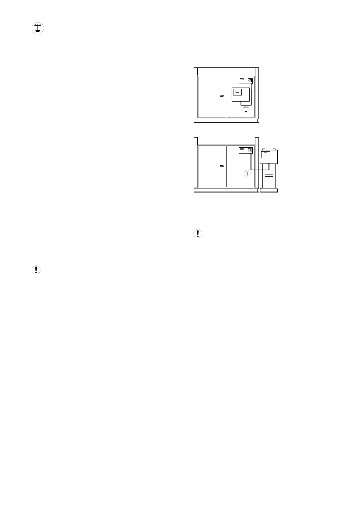
UNIT LOCATION
The VSD V Box is wall or panel mounting using
conventional screw fixings. The maximum distance
between the X8I or X12I and the VSD V Box is 4000ft
(1219 meters) of cable length. The VSD V Box must be
located adjacent to the compressor unit within 6ft (2m)
with total length of interconnecting cables not exceeding
10ft (3m).
POWER SUPPLY
A fused switching isolator must be installed to the main
incoming power supply, external to the VSD V Box. The
isolator must be fitted with a properly sized fuse to
provide adequate protection to the power supply cable
used (in accordance with local electrical and safety
regulations).
1 2 3 4
L
N
N LE
XPM-TAC24
EE
X01
X04
VOLTAGE SELECT
X04
VOLTAGE SELECT
1
234
1
234
230Vac
115Vac
Power Supply Terminals
Ensure that the voltage select input is properly
jumpered for the incoming power. Default voltage
configuration is 230Vac.
RS485 NETWORK
The VSD V Box is equipped with an RS485 network
communications capability using the ir485 protocol. The
VSD V Box is intended to operate as part of the X8I or
X12I Automation System. Connection to the system
management unit is two-wire, twisted pair, ground (earth)
shielded, RS485 data link. Connect the RS485 data
cable wires to terminal X07 located on the VSD V Box
controller.
The cable used between the X8I or X12I and the
VSD V Box is Belden 9841 (or equivalent). It should be
run in grounded conduit and should not be greater than
4000 feet (1219 meters) in length.
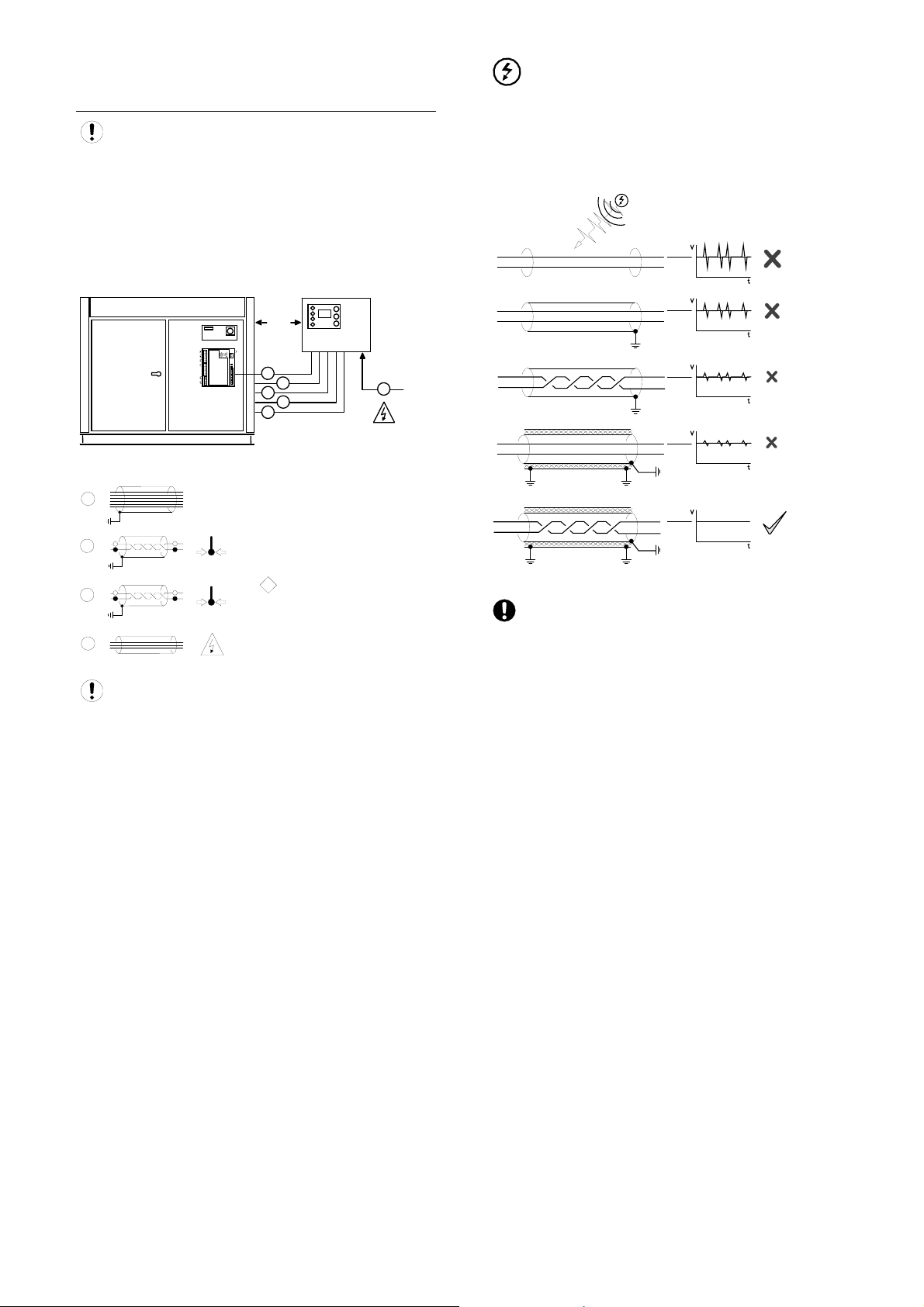
RS485 data communications and other low voltage
signals can be subject to electrical interference. This
potential can result in intermittent malfunction or anomaly
that is difficult to diagnose. To avoid this possibility
always use ground (earth) shielded cables, securely
bonded to a known good ground (earth) at one end. In
addition, give careful consideration to cable routing
during installation.
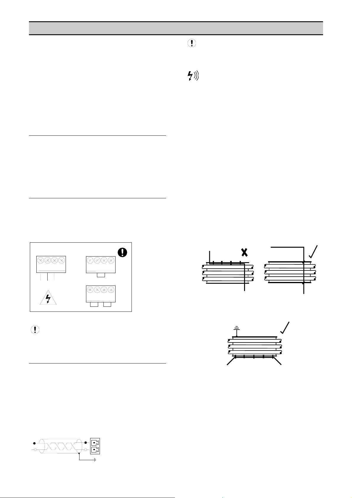
a) Never route an RS485 data communications or low
voltage signal cable alongside a high voltage or 3-phase
power supply cable. If it is necessary to cross the path of
a power supply cable(s), always cross at a right angle.
b) If it is necessary to follow the route of power supply
cables for a short distance (for example: from a
compressor X8I to a wall along a suspended cable tray)
attach the RS485 or signal cable on the outside of an
grounded (earthed) cable tray such that the cable tray
forms an grounded (earthed) electrical interference
shield.
c) Where possible, never route an RS485 or signal cable
near to equipment or devices that may be a source of
electrical interference (for example: 3-phase power
supply transformer, high voltage switchgear unit,
frequency inverter drive module, radio communications
antenna).
L2
L1
Note: Polarity is important.
X07
L2
L1
7
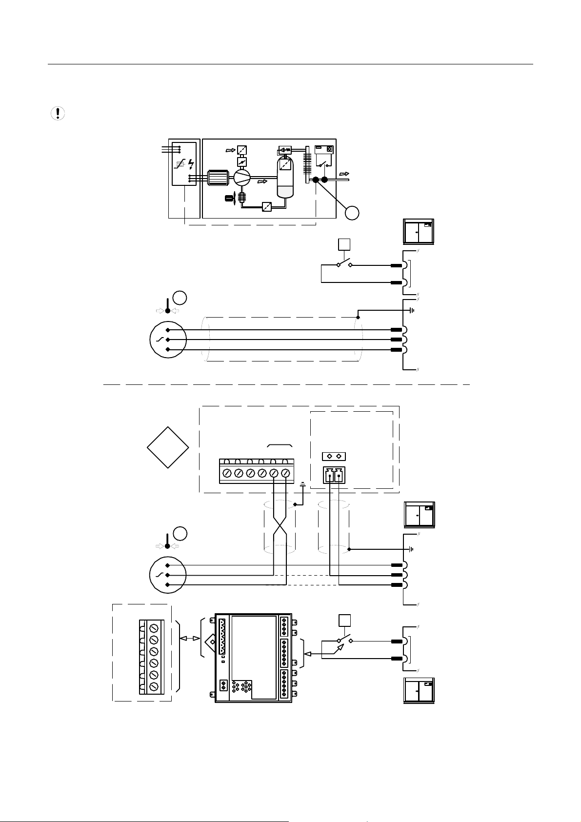
Page 8
VSD V BOX AND PRESSURE SENSOR
CONNECTIVITY
Consult the X8I OR X12I Interconnect and
Application Guide prior to the installation of the VSD V
Box to the pressure sensor on the VSD and the
compressor.
Pressure sensor connectivity is dependent on
compressor and control system type.
Electrical Interference
0-5VDC, 1-5VDC, or 0.5-4.5VDC Pressure Sensors
Voltage sensors and cables carrying low voltage analog
pressure signals are highly susceptible to interference.
C0
4
C0
2
C0
1
i-PCB
6ft,2m
max
LE
D
LE
2
D
1
C0
3
1
2
3
VSD Box
2
3
1
2
3
4
i-PCB
6wire : 18-20 Gau (1.0-1.5mm)ge
Ground (earth) shielded
Delivery Pressure
2wire, twisted pair, 20 gauge
#1
(0.5-1.0mm
?
Internal Pressure
2wire, twisted pair, 20 gauge
#2
(0.5-1.0mm )
2wire + Ground (earth)
115/230Vac, 5A
2
2
,
Ground (earth) shielded
)
2
,
Ground (earth) shielded
Cables identified as ‘3’ are only required for a two
pressure sensor type compressor installation.
4
Always use shielded, braided (armored), foil
wrapped with a drain wire, 18 / 20 AWG (0.5-1.0mm)
maximum, 2-conductor cable no more than 10 feet (3
meters) in length. Ensure the braided steel wire is
securely connected to a known good earth ground at
both ends. Ensure the internal drain wire is securely
connected to a known good earth ground at the VSD
V Box end only.
Failure to protect low voltage pressure signals between
the compressor and VSD V Box will result in unstable
and/or erratic pressure readings; resulting in unstable
and/or erratic compressor regulation behavior.
8
Page 9
Compressor Ground (earth) Circuit Issues
An air compressor that uses an electrical induction main
motor may experience voltage interference generated in
the compressor’s ground (earth) circuits. An induction
motor will generate induction currents in the ground
(earth) circuit when changing state from loaded to
unloaded, or vice versa, condition. Induction motors that
are driven from a variable frequency drive will
continuously induce ground (earth) currents during
normal load and unload operation.
In some instances the induced current flow in the ground
(earth) circuits may manifest as a small voltage
difference between various parts of the compressor’s
ground (earth) system.
Generally this has no consequence and can be ignored.
As the compressor controller experiences minor ground
(earth) reference fluctuations, all parts of the controller
and control circuits will fluctuate with the same induced
ground (earth) voltage simultaneously. The controller will
be unaffected.
In the case of a low voltage signal that is referenced to a
different ground (earth), remote from the compressor, the
situation may represent an issue. As the compressor’s
ground (earth) reference fluctuates the 0V reference for
any voltage signal will also fluctuate. If a remotely
generated voltage signal (from the VSD V Box for
example) does not fluctuate in the same way
simultaneously the compressor controller will detect a
voltage difference in the signal. This will be seen as a
fluctuating pressure display that will generally indicate a
pressure that fluctuates to a lower pressure than actual.
To avoid this situation the VSD V Box must be securely
bonded too, and referenced too, the same ground (earth)
as the compressor controller.
If the VSD V Box is mounted remote from the
compressor, and pressure signal fluctuations are
experienced, the use of a length of ground (earth) cable,
or the ground (earth) of a steel wire cable, will reduce,
but may not resolve, the issue. Any length of conductive
cable or cable screen will have a small resistance to high
frequency current flow. This will generate a minor voltage
differential alone the cable or cable screen resulting in a
voltage difference between the two ends of the cable or
cable screen. The pressure display may continue to
fluctuate.
This situation can be avoided by mounting the VSD V
Box on, or directly adjacent to, the compressor and
connecting the VSD V Box ground (earth) to the
compressor controller ground (earth) with a large cross
section ground (earth) cable or braided conductor.
VSD Box
VSD Box
This action will ensure the VSD V Box experiences the
same ground (earth) circuit fluctuations simultaneously
with the compressor controller.
The necessity to avoid radiated electrical
interference from the compressor still remains,
particularly in the instance of a variable frequency drive.
The use of twisted pair, ground (earth) shielded cable for
low voltage signals internal to the compressor remains
important.
9
Page 10
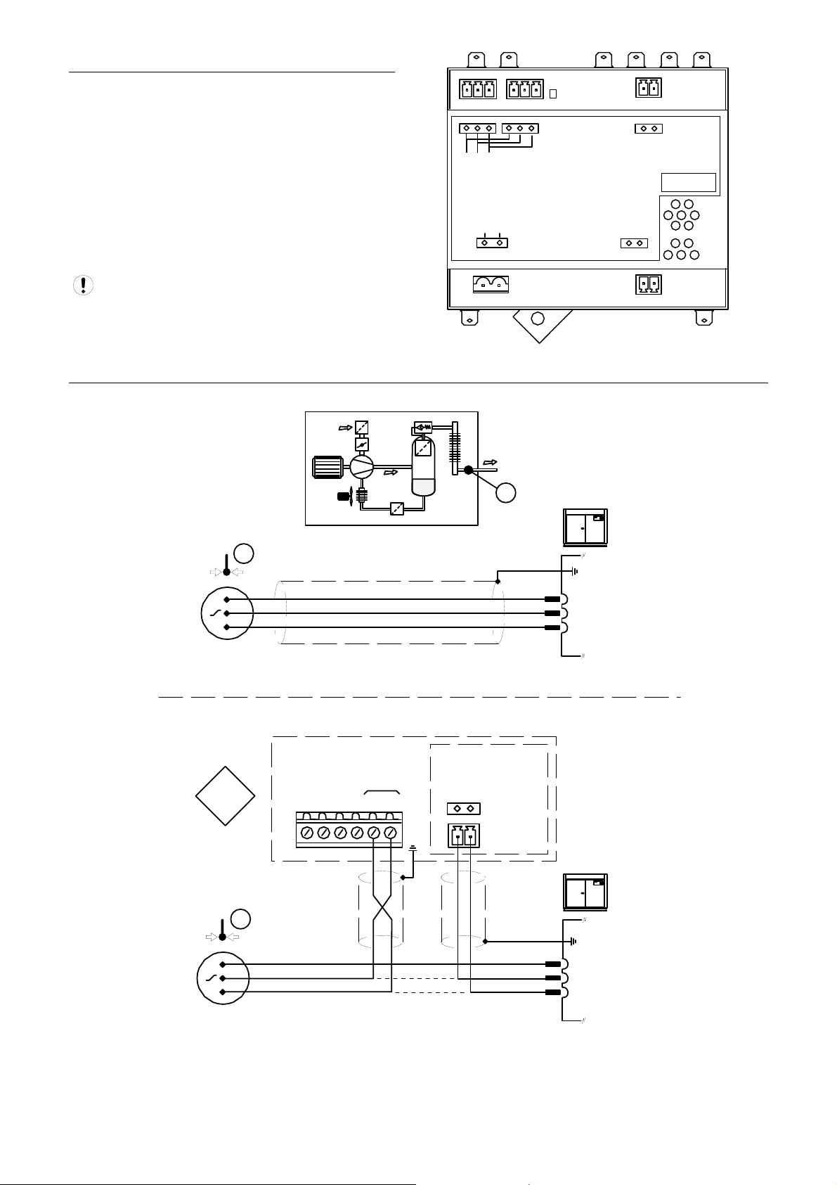
PRESSURE SENSOR CONNECTIONS
Pressure sensor connectivity is dependent on
compressor and control system type.
21
1) Disconnect the compressor pressure sensor wires
from the compressor controller and connect to the VSD V
Box terminals as indicated on the following connection
diagrams.
2) Connect the VSD output pressure signal terminals to
the compressor control system pressure sensor terminals
as indicated on the following connection diagrams.
3213
1
n
2
L
e
L
e
r
X05
c
s
C
X01
D
V
4
2
+
RS485
X04
V
0
Pressure signal output terminals are located on the XPMVo2 module within the VSD Voltage Box.
These terminals are not located on the main terminal
PCB of the VSD V Box
DISCHARGE (DELIVERY) PRESSURE SENSOR INTERCONNECT
1
D
E
L
#1
+VDC(1)
X02
21
+VDC(2)
-
+
2
2
A
A
X03
#2
N
N
A
A
Vo2
1
1
A
A
N
N
A
A
-
+
+
-
IP = 0
1
+VDC
1
VSD Box
IC = 1 0 to 5VDC
IC = 2 1 to 5VDC
IC = 3 0.5 to 4.5VDC
X07
26 28
25 27
29
30
+VDC
+
-
XPM-Vo2
#1
X02
+VDC
signal
0VDC
+
v
-
Delivery
Pressure
Sensor
1
+
-
+VDC
signal
0VDC
+VDC
signal
0VDC
+
v
-
Delivery
Pressure
Sensor
10
Page 11
DISCHARGE (DELIVERY) PRESSURE SENSOR AND INTERNAL PRESSURE SENSOR
INTERCONNECT
Internal = Sump
+VDC
1
+VDC
2
1
IP = 1
+
-
+
-
2
VSD Box
X07
25
26
IC = 1 0 to 5VDC
IC = 2 1 to 5VDC
IC = 3 0.5 to 4.5VDC
l
y
r
a
e
n
v
r
i
l
e
t
e
n
I
D
28 30
27 29
#1
+VDC
+
+VDC
signal
0VDC
+VDC
signal
0VDC
XPM-Vo2
+
v
-
+
v
-
Delivery
Pressure
Sensor
Internal
Pressure
Sensor
#2
+VDC
-
X02
-
+
X03
1
+
-
+
-
+VDC
signal
0VDC
+VDC
signal
0VDC
+VDC
signal
0VDC
+VDC
signal
0VDC
+
v
-
+
v
-
Delivery
Pressure
Sensor
Internal
Pressure
Sensor
2
11
Page 12
VSD COMPRESSOR WITH PRESSURE SWITCH REGULATED COMPRESSOR
INTERCONNECT
Compressor controller loads and unloads using a
pressure switch; VSD unit regulates using +VDC
discharge (delivery) pressure sensor.
See “i-PCB” Interface Connection
1
+
-
IC = 1 0 to 5VDC
IC = 2 1 to 5VDC
IC = 3 0.5 to 4.5VDC
1
4-20mA
P
Delivery
Pressure
Switch
+VDC
signal
0VDC
+
v
-
Delivery
Pressure
Sensor
VSD Box
6
5
4
1
0
X
3
2
1
IP = 0
+
-
VSD Box
25 27
X07
26 28
29
+VDC
30
XPM-Vo2
-
+
#1
X02
1
+VDC
signal
0VDC
+VDC
signal
0VDC
+
v
-
Delivery
Pressure
Sensor
P
Delivery
i-PCB
LED 1 LED 2
Pressure
Switch
12
Page 13

VSD V AND IR-PCB COMPRESSOR
CONNECTIVITY
ir-PCB COMPRESSOR STATUS
MONITORING
An ir-PCB is a requirement for a VSD V Box installation.
The ir-PCB is a DIN rail mountable unit designed to be
installed within the compressor control or switchgear area
and connected to the VSD V Box using a six-wire cable.
The ir-PCB is used for compressor status monitoring and
in some installations for ‘remote load/unload’ or ‘pressure
switch’ regulation control.
C01 C02 C04
i-PCB
C03
246135
LED 1 LED 2
X01
VSD Box
246135
The ir-PCB uses a 12V to 250V ac/dc input voltage
detection system and universal relay contact control
outputs (250Vac/dc @ 5A maximum). Integrated directly
into the circuits of an air compressor, the ir-PCB avoids
the need for additional relays or remote inputs. The irPCB also acts as an electrical barrier between the
compressor and the VSD V Box providing protection and
voltage isolation.
The ir-PCB is fitted with a six-pin terminal C04 for
compressor monitoring. The ir-PCB uses three inputs
(Ready, Run and Loaded) to determine compressor
status. All three status-monitoring input signals are
required.
READY
The ‘Ready’ connection is intended to indicate that the
compressor is in a ‘started’ state, has no operational
inhibiting fault condition and is ready to respond to VSD
V Box regulation without manual intervention.
Ready Input
READY LAMP
+V
READY
RUN
ALARM
C04
0V
The READY input will accept 12V to 250V ac (50/60Hz)
or dc.
Caution: Do not connect a voltage greater than
250Vac/dc to this input.
This input must be connected to the terminals of a ‘ready’
or ‘operational’ lamp, or other circuit of the compressor
control system, that will be energized when the
compressor is in started (standby or running) condition.
The voltage to this input must de-energies when the
compressor is stopped and unavailable to produce air
upon a load signal or the Emergency Stop button is
pressed or when the compressor experiences a fault that
prevents the compressor from running.
When the compressor ready lamp, or other control circuit,
is energized the ir-PCB will detect the voltage and signal
the VSD V Box that the compressor is ready and
available to load and produce air when a load request
signal is given.
The ir-PCB input common terminal must always be
connected to the neutral, common or 0V line of the
applied input
13
Page 14

Ready Input, Alternative Connection Method:
In instances where a convenient voltage signal for a
compressor ready condition is not available the ‘Ready’
input can be connected directly to a constant compressor
control system power supply voltage (12V to 250Vac or
dc). This will signal the VSD V Box that the compressor is
ready and available at all times when power is applied to
the compressor. The VSD has a built-in function to
determine when a compressor is not responding, or is in
a shutdown condition, regardless of a constant ready
signal. If the VSD V Box requests a compressor to
run/load, but fails to detect a RUN signal within 60
seconds, the VSD V Box will regard the compressor as
‘not ready’ and indicate the compressor as not available.
If a RUN signal is detected at any time, the VSD V Box
will automatically reset the compressor ‘not ready’
condition and re-establish control.
+Vac
F1
0Vac
READY
Safety: Never connect the READY input positive
connection directly to the output of a control system
transformer, always connect after a fuse or circuit
breaker.
If a normally closed contact of an Emergency Stop button
is included in the compressor power supply circuit,
connect after the Emergency Stop button contacts. This
will instantly indicate a compressor ‘not ready’ condition if
the Emergency Stop button is activated.
RUNNING
MAIN (LINE) CONTACTOR
0V
+V
For a fixed speed air compressor this input can be
connected to the control terminals A1 and A2 (coil) of the
main starter contactor of the compressor. When the
compressor control system energizes the main contactor,
the ir-PCB will detect the voltage across the contactor
coil terminals and signal the VSD V Box that the
compressor is running.
MAIN (LINE) CONTACTOR
+V
+V
AUXILIARY SWITCH
ALARM
RUN
C04
READY
0V
0V
Alternatively, if the main contactor coil voltage is greater
than 250Vac, a contactor auxiliary switch can be used to
apply a suitable voltage to the ‘Run’ input terminals.
For a ‘Variable Speed’ air compressor alternative
methods of determining a running condition may have to
be established.
The majority of VSD compressors are fitted with a single
main motor contactor but in most instances this contactor
energizes at compressor initialization and remains
energized regardless of motor running. The following
alternative signals may be used to indicate motor running
in most cases:-
1) The ‘Fan’ contactor – in instances where the
cooling fan energizes and de-energizes in
conjunction with the main motor.
2) The compressor controller ‘run’ signal to the
‘Inverter Drive Unit’; an interface relay may be
required.
The ir-PCB input common terminal must always be
connected to the neutral, common or 0V line of the
applied input voltage.
READY
RUN
ALARM
C04
The RUN input will accept 12V to 250V ac (50/60Hz) only
(DC cannot be used).
Caution: Do not connect a voltage greater than 250V to
this input.
12V to 250Vac must be applied to the ‘Run’ terminals
when the compressor motor is running.
14
Page 15

LOADED
ALARM = LOAD
The VSD V Box uses the ir-PCB ALARM input to detect
the load condition of the compressor. There is no Alarm
input facility on the ir-PCB when used with a VSD V Box.
An auxiliary ‘Alarm’ input terminal within the VSD V Box
is available.
A fault, that stops the compressor, and/or prevents
the compressor from running, is determined from the
‘Run’ and ‘Ready’ inputs; Alarm detection is optional and
is not a requirement.
+V
LOAD
SOLENOID
0V
PRESSURE SWITCH REGULATION
CONTROL
In ‘Pressure Control’ mode the VSD V Box will also
control the ir-PCB load/unload relay outputs in
accordance with the set load and unload pressure set
points. The ir-PCB load/unload relay contacts can be
used for compressor controllers that have ‘pressure
switch’ load/unload regulation (fixed speed and variable
speed types).
ir-PCB Internal Output Circuits
OUT
NO
OUT
OUT
NC
1
C
3
2
C
Load
C
Seq
IN
NO
IN
C
IN
NC
READY
ALARM
RUN
C04
The LOAD input will accept 12V to 250V ac (50/60Hz) or
dc.
Caution: Do not connect a voltage greater than
250Vac/dc to this input.
The ‘Load’ input can be connected to the terminals of the
compressor’s load solenoid; or other accessible part of
the control circuit that is energized when the compressor
is loaded.
The ir-PCB input common terminal must always be
connected to the neutral, common or 0V line of the
applied input voltage.
For a compressor that is not equipped with a load
solenoid (a compressor that is loaded at all times while
running) the ‘Load’ input can be connected to the ‘Run’
input.
Running
0v
Contacts :-
SEQ
Relay
1&2
LOAD
Relay
3
250Vac/dc @ 5A
maximum
C03
GND
LOAD
SEQ
UNL
CONT
24Vac
The C01 and C02 terminal functions of the ir-PCB are
intended to control load and unload regulation of the
compressor.
+20VDI2DI1
ALARM
RUN
C04
READY
15
Page 16

Pressure Switch Regulation:
For air compressors fitted with an electro-mechanical
pressure switch a six-pin terminal C02 has been provided
to enable connection to a pressure switch that has a two
wire or three-wire connection.
When connected the pressure switch remains in circuit. If
the VSD V Box is stopped or experiences a failure or loss
of power, pressure control will automatically revert back
to the pressure switch and the compressor will continue
to operate in ‘Local’ mode.
The NC (normally closed) and NO (normally open)
terminal references of the ir-PCB are related to internal
connection functions and should not be referenced to the
connections of a compressor pressure switch (which will
generally be in reverse order).
Caution: Lethal voltages may be present on the
terminals of the air compressor pressure switch. Isolate
the air compressor power supply before starting any
work.
Two Wire Pressure Switch Connections:
Remote Load/Unload Regulation:
For air compressors fitted with a ‘Remote/Local Pressure
Regulation’ and a ‘Remote Load/Unload’ digital input a
four-pin terminal C01 has been provided.
This terminal provides volt free contact closure for load
control and also provides volt free contact closure for
remote pressure control enable.
A remote load enable input provides the facility to change
the compressor load regulation from internal control to a
remote switching source.
Compressors that use electronic pressure detection
but are not equipped with a remote pressure control
enable feature will not automatically revert to local control
if the VSD V Box is stopped or experiences a fault or loss
of power.
Load and Sequence Connection:
COMPRESSOR CONTROLLER
INPUTS
+V
LOAD
SOLENOID
C
C
C
O
N
N
OUT
C02
C
O
N
N
IN
Three Wire Pressure Switch Connections:
SOLENOID
+V
RUN-ON
LOAD
TIMER
0V
Remote Load
Local/Remote
or
Inputs Common
Remote Load Enable
C01
D
C
C
Q
A
E
S
O
L
Compressor controller inputs common voltage may
be 0V or +V.
0V
C
C
C
O
N
N
OUT
C02
C
O
N
N
IN
16
Page 17

The local/remote pressure regulation input and/or remote
load input logic of some electronic pressure sensor type
controllers are reversed, in this instance the ‘pressure
switch’ outputs (terminal C02) can be used to establish
alternative logic control connections.
For Example:
If the compressor controller ‘Local/Remote Pressure
Control’ input is a normally open type; Remote when
closed, but the ‘Remote Load’ input is a normally closed
type; load when open, the ir-PCB pressure switch
terminal contacts can be used to achieve the correct
switching logic.
C02
NO
OUT
C
NC
NO
IN
C
NC
Examine the ir-PCB internal output circuit diagram to
establish any desired switching logic that may differ from
normal practise.
Do not attempt to utilise the Load/Seq ‘Electronic
Pressure Control’ (terminal C01) and the ‘Pressure
Switch Control’ (terminal C02) output connections at the
same time. These two output functions are internally
connected and a short circuit condition and/or
malfunction may result.
Service Maintenance Switch:
(Optional - dependant on management system controller
model)
The ir-PCB is equipped with a volt-free input (terminal
C05) that can be used to remove the compressor from
management system control, without generating a fault
condition, during maintenance or servicing periods.
C05
When the ‘Service Maintenance Switch’ input terminal
pins are connected together, using a volt-free switching
contact, the management unit will indicate that the
compressor is not available but will not generate an
Alarm, Trip or Shutdown condition. The management unit
will also remove the compressor from the sequence
strategy and substitute with an alternative available
compressor if necessary. When the ‘Service
Maintenance Switch’ inputs are open circuit again the
compressor will automatically be accepted back in to the
sequence strategy and will be utilized as and when next
required.
Local/Remote
common
Remote Load
common
1
2
The use of a ‘key switch’ is recommended for this
purpose in order to prevent the switch contacts being
inadvertently left in the closed circuit condition after
service maintenance is complete.
DO NOT connect any external voltage source to the
pins of terminal C05.
This function is only available with management
system unit models equipped with ‘Service Maintenance
Switch’ functionality. For management units that do not
provide this function the pins of terminal C05 must not be
utilized. Activating the ‘Service Maintenance Switch’
function with a management unit not equipped for the
function will disrupt the ‘Compressor Loaded’ detection
facility.
Auxiliary Alarm Input (Option)
The VSD V Box is equipped with an auxiliary ‘Alarm’
input. This input can be used to detect a compressor
‘Warning’ or ‘Alarm’ condition. The input can also be
used to detect an ‘Alarm’ condition of auxiliary equipment
associated with the compressor.
The management system unit will regard the alarm as a
compressor alarm.
X04
6
1
5
1
4
1
3
1
Aux Alarm
As default the auxiliary ‘Alarm’ input is normally open,
Alarm on closed circuit condition. If required this can be
reversed in the VSD V Box setup menu to be normally
closed, alarm on open circuit.
Auxiliary Trip Input (Option)
The VSD V Box is equipped with an auxiliary ‘Trip’ input.
The input can be used to detect a compressor shutdown
trip condition. The input can also be used to monitor
other auxiliary equipment associated with the compressor
and initiate a compressor trip condition.
The management system unit will regard the trip as a
compressor shutdown trip and will remove the
compressor from sequence; the compressor will run-on
for the compressor controller’s set run-on time and stop.
X04
6
1
5
1
4
1
3
1
Aux Trip
As default the auxiliary ‘Trip’ input is normally open, Trip
on closed circuit condition. If required this can be
reversed in the VSD V Box setup menu to be normally
closed, trip on open circuit.
The maximum cable length for Auxiliary ‘Alarm’ or
‘Trip’ inputs is 100m.
17
Page 18

Speed Monitoring Input (Option)
The VSD V Box is equipped with a ‘speed detection’
input designed to function with a ‘VSD Speed Monitoring
Kit’ (available separately). This optional feature will
provide all required functionality to enable total synergy
with the energy control, VSD compressor aware,
functions of the management system unit.
X05
2
2
1
2
0
2
9
1
8
1
7
1
rpm
+
Remote Outputs
Compressor Running:
The VSD V Box is equipped with a volt-free relay contact
output (R5) to indicate when the compressor is detected
as running. The output contacts will close when the
compressor is running.
Group Alarm:
The VSD V Box is equipped with a volt-free relay contact
output (R6) to indicate Group Alarm. The Group Alarm
relay contacts are normally closed and will open in the
following conditions:-
1) VSD V Box power failure
2) VSD V Box internal fault condition
3) Input pressure sensor fault
4) Compressor ‘Not Ready’
X09
4
R6
R5
3
3
3
2
3
1
3
X08
Group Alarm
Compressor
Running
Relay contact rating:
CE: 250V @ 5A max
UL: 115V @ 5A max
18
Page 19

SECTION 5 — DISPLAY AND MENU OPERATION
OPERATION
User Interface
a
b
g
f
h
a) START Button
b) RESET Button
c) STOP Button
d) MENU Button
e) ENTER Button
f) CANCEL Button
g) UP, Plus Button
h) DOWN, Minus Button
Display
Status Symbols
The Status display will continuously show the
current state of the VSD Box (C) by using the
following icons.
Power Failure Auto Restart (always on)
Communicating with System Management Unit
c
Flashing - No Communications System
Management Unit
Compressor Running
Compressor Loaded
d
e
psi
Flashing - Not Responding, Compressor Not
Running When Required
Flashing - Not Responding, Compressor Not
Loading When Required
Service Maintenance function active
Discharge (delivery) pressure or Internal
Pressure has exceeded the maximum set limit
Compressor Not Ready
Fault, Auxiliary Input Alarm/Trip
Pressure Control OFF or inhibited
Load Request to compressor
Unload Request to compressor
Pressure Control Active
Indicators
Run Indicator (Green LED)
OFF - Pressure Control Off, Stopped
The primary display value (A) will continuously show the
detected ‘Delivery’ pressure. The pressure is derived
from the compressor ‘Delivery’ pressure sensor and the
displayed value is not manipulated or adjusted.
The compressor controller ‘Pressure Display’ may
not represent the actual true local pressure(s) when VSD
V Box ‘Pressure Control’ is active. Use the VSD V Box
‘Input’ pressure display(s) for local pressure reference.
The ‘User Menu’ item display (B) will show the selected
user menu item. Press UP or DOWN to scroll through the
display ‘items’ list.
Flashing - Pressure Control ON, waiting for
compressor to respond
ON - Pressure Control On, Started
Fault Indicator (Red LED)
OFF – No fault
Flashing – VSD V Box Fault Condition
(see Fault Codes)
The VSD V Box will report that the compressor is ‘Not
Available’ to the system management unit when the VSD
V Box is in a stopped or fault condition.
19
Page 20

Start
Press START to activate VSD V Box pressure control.
The run indicator will illuminate or flash.
The compressor must be in a started state (running
or in standby) before VSD V Box pressure control will
function.
When started the VSD V Box will begin to manipulate the
pressure signal(s) to the compressor controller –
‘Pressure Control’ is active.
Pressure Control will de-activate
automatically if communications with the system
management unit is disrupted or not connected; the
detected pressure from the pressure sensor(s) is retransmitted to the compressor control directly.
When communications are re-established the
VSD V Box will automatically re-activate ‘Pressure
Control’.
Stop
Press STOP to de-activate VSD V Box pressure control.
The run indicator will extinguish.
When stopped the VSD V Box will not manipulate or
adjust the pressure signal(s) to the compressor
controller; the detected pressure from the pressure
sensor(s) is re-transmitted to the compressor control
directly.
The VSD V Box will report that the compressor is ‘Not
Available’ to the system management unit when the VSD
V Box is in a stopped condition.
During compressor service or routine maintenance
the VSD V Box can be stopped to return the compressor
to normal local pressure regulation.
Compressor Status
The detected status of the compressor is indicated by the
VSD V Box display status symbols (see Status Symbols)
VSD V Box Status
VSD V Box operation is indicated by the ‘Run’ LED
indicator (see Indicators). Pressure Control status is
indicated by the ‘pressure’ status symbols (see Status
Symbols).
User Menu Items
To view the ‘User Menu Items’ press UP or DOWN. The
‘Item’ display value will scroll through the available items.
P1 ‘Delivery’ output pressure transmitted to the
compressor controller.
P2* ‘Internal’ output pressure transmitted to the
compressor controller.
SP** Percent motor speed
C> VSD V Box Status
(*) The ‘Internal’ output pressure item is only shown if the
‘Internal’ pressure control function is activated (IC = 2).
(**) The percentage motor speed item is only shown if a
‘Speed Monitoring Kit’ is fitted and the function is
activated (Menu P08).
Delivery Output Pressure:
The delivery output pressure is manipulated during
‘Pressure Control’ and will differ from the actual ‘Input
Delivery’ pressure displayed as the main display value.
Pressure control function can be observed by comparing
the ‘Output’ discharge (delivery) pressure with the actual
detected ‘Input’ discharge (delivery) pressure. The two
pressures will be identical when ‘Pressure Control’ is not
active.
Internal Output Pressure:
The internal output pressure is manipulated during
‘Pressure Control’ to simulate and maintain the actual
detected differential between the ‘Input’ discharge
(delivery) pressure and the ‘Input’ Internal pressure. This
functionality allows compressor controller differential
pressure monitoring functions to be maintained
regardless of VSD V Box output pressure signal
manipulation.
Percentage Motor Speed:
The percentage of detected motor speed compared to
maximum motor speed. This value provides a direct
indication of variable speed compressor output
regulation.
VSD V Box Status:
The central ‘item’ display value (B) is the compressor
system identification number (network address number).
This is the same as the compressor system identification
number shown on the system management unit.
The ‘right hand’ display value indicates the VSD V Box
status condition (see Status Block Diagram).
Power Failure Auto-Restart
Power failure auto restart is always active and cannot be
de-activated.
The VSD V Box will re-start if the VSD V Box was in an
operational started status before the break or failure of
the main power supply occurred.
The VSD V Box will not re-start if it was not in an
operational started status before the break or failure of
the main power supply occurred.
20
Page 21

SECTION 6 — COMMISSIONING
COMMISSIONING PROCEDURE
It is recommended that installation and commissioning be
carried out by an authorized and trained product supplier.
Information regarding the compressor control system,
method of operation and regulation settings, is required.
Knowledge of VSD compressor regulation methods,
experience working with compressor control systems and
basic principle knowledge of compressed air systems, is
also required to be able to successfully install and
commission this product.
PHYSICAL CHECKS
Before applying power to the VSD V Box ensure that the
power supply connections are correct and secure and
that the operating voltage selector is set correctly for the
power supply voltage in use; 115Vac or 230Vac (+-10%),
50/60Hz; see ‘Installation’.
Check and ensure all pressure sensor, output pressure
signal and ir-PCB connections are correctly installed and
secure.
COMPRESSOR PRESSURE SET POINTS
Establish the following pressure set point values from the
compressor control system.
Establishing the correct compressor pressure set
point values is critical to successful VSD V Box
operation.
1) Compressor ‘Load’ pressure set point.
The pressure at which the compressor will start/load.
On fully integrated VSD compressor controllers this value
may be represented as the ‘Target Pressure’ level.
2) Compressor ‘Unload’ pressure set point.
The pressure at which the compressor will stop/offload.
On fully integrated VSD compressor controllers this value
may be represented as the ‘Controlled Stop Pressure’
level.
3) Compressor ‘Target’ pressure set point.
For VSD type compressors this is the pressure that the
variable speed drive is set to maintain.
This value will generally be the same as the ‘load’
pressure set point for variable speed compressors that
have fully integrated VSD control systems. For variable
speed compressors that do not have fully integrated
control systems this value will generally be the mid-point
between the ‘load’ and ‘unload’ pressure set points.
If the variable speed ‘target’ pressure is set separately
from the compressor controller (in the variable speed
drive controller menu or using a potentiometer connected
to the variable speed drive controller), then the
compressor controller is not a fully integrated type. In this
instance the ‘target’ pressure may have to be determined
by observation and/or experiment.
For fixed speed compressors the ‘target’ pressure can be
set at the mid-point between the compressor ‘load’ and
‘unload’ pressure set points.
4) The maximum Discharge (delivery) pressure level (and
maximum Internal pressure level if used) set in the
compressor controller. This value will be the Excess or
High pressure Alarm safety level. On fully integrated VSD
compressor controllers this value may be represented as
the ‘Immediate Stop Pressure’ level.
COMPRESSOR
Pressure Set Points
Excess or Alarm Pressure
7psi (0.5bar) min
Unload Pressure
Pressure
Target Pressure
Load Pressure
7psi (0.5bar) min
COMPRESSOR
Pressure Set Points
Immediate Stop Pressure
7psi (0.5bar)) min
Controlled Stop Pressure
Pressure
Target Pressure
7psi (0.5bar) min
If the compressor pressure set points have been set with
small differentials then the pressure set points of the
compressor will require adjustment before proceeding.
It is recommended that the pressure differential between
the ‘load’ and ‘unload’ (or ‘target’ and ‘controlled stop’)
pressures is a minimum of 7psi (0.5bar).
It is recommended that the pressure differential between
the ‘unload’ and ‘excess’ (or ‘controlled stop’ and
‘immediate stop’) pressures is a minimum of 7psi
(0.5bar).
21
Page 22

VSD V BOX CONFIGURATION
Apply power to the VSD V Box.
If the VSD V Box automatically starts (the green started
indicator illuminates or flashes) press the STOP button.
Using the VSD V Box menu routines, set the ‘IC’ (I/O
Configuration - Type) item of menu P03 to the correct
setting for the pressure sensor input/output configuration.
See Menu Items and Settings.
VSD V Box Network Address
Each VSD compressor connected to the Automation
System unit must be assigned a unique compressor
identification number (1 to the maximum number of
compressors support by the X-Series controller). This
number will be the ‘network address’ number for the
compressor. The number should be clearly marked on
the compressor for identification purposes.
When connecting a compressor(s) to the VSD Box,
always use the Automation System unit’s unique
identification number as the compressor ‘network
address’ number.
Using the VSD Box menu routines, set the ‘Ad’ (Network
Address) in menu P03 to the Automation System unit’s
compressor identification number.
Input Pressure Sensor(s)
The offset and range of the pressure sensor(s) used on
the compressor must be established for VSD V Box
pressure sensor calibration. Generally this information is
indicated on the pressure sensor label.
The majority of pressure sensor(s) have a minimum
pressure (offset) of 0(zero) bar gauge with a ‘range’
applicable to the application. For example 0 to 232 psi
(0.0 to 16.0 bar) - where 0(zero) psi (0.0(zero) bar) is the
‘offset’ minimum and 232 psi (16.0 bar) is the ‘range’ or
maximum.
Some pressure sensor(s) have non-zero offset. For
example -14.5 psi (minus -14.5), (-1.0 bar) (minus 1bar)
to 218 psi, 15bar; this type of pressure sensor can
measure negative or vacuum pressure. In this instance
the ‘offset’ is -14.5 psi (minus -14.5), (-1.0 bar) (minus
1bar)) and the ‘range’ is 232 psi (16.0 bar). Remember
the ‘range’ is the difference between the minimum and
maximum values and not the maximum value referenced
to 0(zero) bar ‘atmospheric’.
The correct ‘offset’ and ‘range’ values of each pressure
sensor are required for VSD V Box ‘input’ pressure
sensor calibration.
The main value display should show a pressure value; for
example 0 psi (0.0 bar). If the display shows dashes (- - -
-) check the ‘Delivery‘ pressure sensor connections.
Wire polarity is important.
If an ‘Internal’ pressure sensor is in use press DOWN to
view the ‘P2’ pressure value in the User menu ‘items’
display. The ‘P2’ value display should show a pressur e
value; for example 0 psi (0.0 bar). If the display shows
dashes (- - - -) check the ‘Internal‘ pressure sensor
connections.
At this stage the displayed pressure values will probably
be incorrect; this is normal.
Calibrate the input ‘Delivery’ pressure sensor, and input
‘Internal’ pressure sensor if used, following the input
‘Pressure Sensor Calibration’ procedure below:
In many instances where a 0 to 5VDC pressure
sensor is indicated or specified the actual operation is 1
to 5VDC. Request conformation from the compressor
supplier or manufacturer.
Input and Output pressure calibration is critical for
successful VSD V Box operation.
Input Pressure Sensor Calibration
Using the VSD V Box menu navigation procedure, select
menu page P04 (Input Pressure Calibration). The ‘items’
of this menu enable calibration of the pressure sensor(s)
connected to the VSD V Box.
Enter the ‘OFFSET’ value for the ‘Delivery’ pressure
sensor in the ‘Do’ menu item.
For example: if the pressure sensor is 0 tom 232 psi (0 to
16.0 bar), enter 0 psi (0.0 bar) as the offset value; if the
pressure sensor is -14.5 to 218 psi, (–1.0 to 15 bar) enter
-14.5 psi (minus -14.5), (-1.0 bar) (minus 1bar) as the
offset value.
Enter the ‘RANGE’ value for the ‘Delivery’ pressure
sensor in the ‘Dr’ menu item.
For example: if the pressure sensor is 0 tom 232 psi ( (0
to 16.0 bar) enter 232 psi (16.0 bar) as the range value; if
the pressure sensor is -14.5 to 218 psi, (–1.0 to 15 bar)
then the range value is also 232 psi (16.0 bar).
When the ‘Delivery’ pressure sensor offset and range
menu items are selected the menu page display value
will change to show the actual detected ‘Delivery’
pressure measurement. This value can be used to
compare with a ‘known’ pressure applied to the ‘Delivery’
pressure sensor for accurate calibration purposes. An
independent and accurate means of measuring the
applied pressure is required.
1) Subject the ‘Delivery’ pressure sensor to atmosphere
(0bar).
2) Adjust the ‘Do’ pressure ‘offset’ value until the
‘Delivery’ pressure displayed by the VSD V Box sho ws
0(zero) bar.
3) Apply a known pressure to the ‘Delivery’ pressure
sensor. It is recommended that the applied pressure is
representative of normal working pressure levels. It is not
important if the applied pressure is static or continuously
fluctuating.
4) Adjust the ‘Dr’ pressure ‘range’ value until the
‘Delivery’ pressure displayed by the VSD V Box sho ws
the same as the ‘known’ applied pressure.
If an ‘Internal’ pressure sensor is also in use, follow the
same procedure described above applying adjustments
to the ‘Io’ (Internal offset) and ‘Ir’ (Internal range) menu
items. When these menu items are selected the menu
page display value will change to show the actual
detected ‘Internal’ pressure measurement.
Wire polarity is important.
22
Page 23

Output Pressure Signal Calibration
Using the VSD V Box menu navigation procedure, select
menu page P05 (Output Pressure Calibration). The
‘items’ of this menu enable calibration of the pressure
signal(s) transmitted to the compressor controller.
Enter the ‘OFFSET’ value for the ‘Delivery’ pressure
signal in the ‘Do’ menu item. Set this value will to same
as the initial ‘Delivery’ pressure sensor input ‘offset’.
Enter the ‘RANGE’ value for the ‘Delivery’ pressure
signal in the ‘Dr’ menu item. Set this value to the same as
the initial ‘Delivery’ pressure sensor input ‘range’.
When the output ‘Delivery’ pressure signal offset and
range menu items are selected the menu page display
value will change to show the actual detected input
‘Delivery’ pressure measurement. This value represents
the pressure the VSD V Box is attempting to transmit to
the compressor controller and can be used to compare
with the compressor controller’s displayed pressure
value.
1) Subject the input ‘Delivery’ pressure sensor to
atmosphere (0bar).
2) Adjust the ‘Do’ pressure signal ‘offset’ value until the
compressor controller’s discharge (delivery) pressure
display value shows 0(zero) bar.
3) Apply a known pressure to the input ‘Delivery’
pressure sensor. It is recommended that the applied
pressure is representative of normal working pressure
levels. It is not important if the applied pressure is static
or continuously fluctuating.
4) Adjust the ‘Dr’ pressure signal ‘range’ value until the
compressor controller’s discharge (delivery) pressure
display value shows the same as the VSD V Box
discharge (delivery) pressure.
If an ‘Internal’ pressure sensor is also in use, follow the
same procedure described above applying adjustments
to the ‘Io’ (Internal offset) and ‘Ir’ (Internal range)
pressure output signal menu items. When these menu
items are selected the menu page display value will
change to show the actual detected ‘Internal’ pressure
measurement.
It is recommended that Input and Output pressure
calibration is examined, and adjusted if necessary, on a
routine periodic basis.
23
Page 24

PRESSURE SET POINTS
Establishing and implementing the correct pressure
set points is critical for successful VSD V Box operation.
Using VSD V Box menu navigation, select menu page
P03 (Configuration).
1) Set the ‘Dm’ Discharge (delivery) pressure Maximum
Limit) to the compressor’s ‘Excess Discharge (delivery)
pressure Alarm’ or ‘Immediate Stop’ pressure setting.
2) If an ‘Internal’ pressure sensor is in use set the ‘Im’
(Internal Pressure Maximum Limit) to the compressor’s
‘Excess Internal Pressure Alarm’ pressure setting.
Typically this value will be at least 12psi (0.8bar) above
the excess or alarm ‘delivery’ pressure limit.
Using VSD V Box menu navigation, select menu page
P01 (Pressure Set Points).
1) Set the ‘Pu’ (Unload) pressure set point to the
compressor’s ‘Unload’ or ‘Controlled Stop’ pressure set
point value.
2) Set the ‘Pt’ (Target) pressure set point to the ‘target’
pressure setting established for the compressor.
3) Set the ‘PL’ (Load) pressure set point to the
compressor’s ‘Load’ or ‘Target’ pressure set point value.
VSD V Box Pressure Set Point Control:
When the VSD V Box ‘loads’ the compressor it will force
the output ‘Delivery’ pressure signal to a pressure value
3psi (0.2bar) below the set ‘Unload’ pressure set point.
This manipulation will force the compressor to respond to
the low pressure value and the compressor will load.
When the VSD V Box detects the compressor has loaded
the pressure signal is returned to normal active ‘pressure
control’ values.
When the VSD V Box ‘unloads’ the compressor it will
force the output ‘Delivery’ pressure signal to a pressure
value 3psi (0.2bar) above the set ‘Load’ pressure set
point. This manipulation will force the compressor to
respond to the high pressure value and the compressor
will unload. The VSD V Box will hold this pressure value
to maintain offload operation regardless of actual
discharge (delivery) pressure fluctuations.
COMPRESSOR
Pressure Set Points
Excess or Alarm Pressure
e
Unload Pressure
r
u
s
s
e
r
Target Pressure
P
Load Pressure
COMPRESSOR
Pressure Set Points
Immediate Stop Pressure
e
Controlled Stop Pressure
r
u
s
s
e
r
P
Target Pressure
Pressure Set Points
- Unload Pressure
Pu
=
=
- Target Pressure
PT
- Load Pressure
PL
Pressure Set Points
- Unload Pressure
Pu
- Target Pressure
PT
& PL - Load Pressure
VSD Box
VSD Box
Pu +0.2bar
Pu -0.1bar
PL -0.2bar
Pu +0.2bar
Pu -0.1bar
PL -0.2bar
VSD Box
Control Pressures
Unload Request Pressure
Max Control Pressure Limit
Load Request Pressure
VSD Box
Control Pressures
Unload Request Pressure
Max Control Pressure Limit
Load Request Pressure
24
Page 25

SECTION 7 — SYSTEM CONFIGURATION
DISPLAY ITEM STRUCTURE
All value, parameter or option selection displays are
grouped into menu lists. Items are assigned to a list
according to type and classification. Items that can be
used to select options or modify functions are assigned to
‘menu mode’ lists. Items that a User may require to view
during routine operation, detected pressure for example,
are assigned to the normal operational mode list. Lists
are identified by page number; the normal User display
list is page ‘P00’. All parameters and options are
assigned to menu mode pages ‘P01’ or higher. All Page
‘P00’ items are view only and cannot be adjusted.
Normal Operational Mode (Page P00)
At controller initialization, all display elements and LED
indicators are switched on for three seconds, the display
will then show the software version code for a further 3
seconds before initialization is complete and the normal
operating display (Page P0) is shown. In page P00
‘normal operational display mode’ the main display will
continuously show the detected discharge (delivery)
pressure and the Item display will show the first item of
the ‘User’ menu. User menu ‘Items’ can be selected
using the Up or Down buttons at any time. Pressing the
Enter button will lock any selected Item display and
inhibit return to the default display. When an Item display
is locked the lock key symbol will slow flash. To unlock
an Item display press Up or Down to view an alternative
Item display or press Reset or Escape. No Item values,
options or parameters can be adjusted in page ‘P00’. If a
fault condition occurs the fault code becomes the first list
item and the display will automatically jump to display the
fault code. More than one active fault code item can exist
at any one time.
ACCESSING THE X12I CONFIGURATION
SCREENS
Access Code
Access to page list displays higher than page ‘P00’ is
restricted by access code. To access menu mode pages
press UP and DOWN together, an access code entry
display is shown and the first code character will flash.
Use PLUS or MINUS to adjust the value of the first code
character then press ENTER. The next code character
will flash; use UP or DOWN to adjust then press ENTER.
Repeat for all four code characters.
If the code number is less than 1000 then the first code
character will be 0(zero). To return to a previous code
character press ESCAPE. When all four code characters
have been set to an authorized code number press
ENTER. An invalid code will return the display to normal
operational mode; page ‘P00’.
Access Code Timeout
When in menu mode, if no key activity is detected for a
period of time the display will automatically reset to the
normal operational display; Page ‘P00’.
Menu Mode Navigation
In menu mode the main value display will flash and show
the Page number. To select a page press UP or DOWN.
For each page the display will show the first Item of the
page list. To view a page list press ENTER, the Page
number will stop flashing and the Item display will flash.
Press UP or DOWN to view the selected page list items.
To select an Item value for modification press ENTER,
the Item display will stop flashing and the Value display
will flash. The value or option can now be modified by
pressing UP(Plus) or DOWN(Minus). To enter a modified
value or option in memory press ENTER; alternatively the
modification can be abandoned, and the original setting
maintained, by pressing ESCAPE.
Page 0
Item 1 Value
Item 2 Value
Item 3 Value
Item 4 Value
Item 5 Value
Item 6 Value
Page 1
Page 2
Page 3
Page 4
Page 5
Item 1 Value
Item 2 Value
Item 3 Value
Item 4 Value
Item 5 Value
25
Page 26

Press ESCAPE at any time in menu mode to step
backwards one stage in the navigation process. Pressing
ESCAPE when the page number is flashing will exit
menu mode and return the display to normal operational
mode; page ‘P00’.
Page 0
to immediately exit menu mode and return to the normal
operational mode display. Any value or option adjustment
that has not been confirmed and entered into memory will
be abandoned and the original setting maintained.
indicates the Item is locked and cannot be modified. This
will occur if the Item is view only (non adjustable) or in
instances where the item cannot be adjusted while the
VSD V Box is in the operational STARTED state.
Item 1 Value
Item 2 Value
Item 3 Value
Item 4 Value
Item 5 Value
Item 6 Value
Press and hold RESET for two seconds at any time
A flashing Key symbol displayed with any Item
Page 1
Page 2
Page 3
Page 4
Page 5
Item 1 Value
Item 2 Value
Item 3 Value
Item 4 Value
Item 5 Value
26
Page 27

MENU ITEMS AND SETTINGS
MENU P00 - User
1 P1 Discharge Pressure - Output (view only)
2 P2 Internal Pressure - Output (view only)
3 SP Percent Speed (view only)
MENU P01 - Pressure Set Points
1 Pu Unload Pressure
2 Pt Target Pressure
3 PL Load Pressure
MENU P02 – Error Log
1 Hr VSD Box Operating Hours
2 01 Error Log #1
to
16 15 Error Log #15
MENU P03 - Configuration
1 P> Pressure Units Select
2 Ad Network Address (Compressor No.)
3 PA Pressure Averaging Factor
4 IC I/O Configuration (Type)
5 IP Internal Pressure Enable
6 Dm Discharge Pressure Maximum Level
7 Im Internal Pressure Maximum Level
MENU P04 – Input Pressure Calibration
1 Do Discharge Pressure ‘Offset’
2 Dr Discharge Pressure ‘Range’
3 Io Internal Pressure ‘Offset’
4 Ir Internal Pressure ‘Range’
MENU P05 – Output Pressure Calibration
1 Do Discharge Pressure ‘Offset’
2 Dr Discharge Pressure ‘Range’
3 Io Internal Pressure ‘Offset’
4 Ir Internal Pressure ‘Range’
MENU P06 / Diagnostics
See ‘Diagnostics’
MENU P08 – Speed Monitoring
1 FL Frequency at Minimum Speed
2 FH Frequency at Maximum Speed
3 C> Control Percentage (view only)
MENU P10 – Unit Configuration
1 D7 Aux Alarm Input Configuration
2 D8 Aux Trip Input Configuration
3 SQ ir-PCB Sequence control hold
4 Ao Analog Output Function (4-20mA)
5 Er Error Log Reset
6 Hr VSD Box Operating Hours Adjust
MENU P16 – Analog Output Diagnostic
See ‘Diagnostics’
Note: Menus P07, 9 and 11 to 15 are not used.
Access Code = 0021
MENU P01 - Pressure Set Points
Pu: Unload Pressure
Compressor ‘Unload’ pressure set point: The pressure at
which the compressor will stop/unload. On fully
integrated VSD compressor controllers this value may be
represented as the ‘Controlled Stop Pressure’ level. Set
the ‘Pu’ (Unload) pressure set point to the compressor’s
‘Unload’ or ‘Controlled Stop’ pressure set point value.
Pt: Target Pressure
Compressor ‘Target’ pressure set point. For VSD type
compressors this is the pressure that the variable speed
drive is set to maintain. Set the ‘Pt’ (Target) pressure set
point to the ‘target’ pressure setting established for the
compressor.
PL: Load Pressure
Compressor ‘Load’ pressure set point: The pressure at
which the compressor will start/load. On fully integrated
VSD compressor controllers this value may be
represented as the ‘Target Pressure’ level. Set the ‘PL’
(Load) pressure set point to the compressor’s ‘Load’ or
‘Target’ pressure set point value.
Establishing and maintaining the correct pressure
set point values (Pu, Pt and PL ) is critical to the
successful operation of VSD Box control functions.
See ‘Commissioning - Pressure Set Points’
MENU P02 - Error Log
The first item of the log error menu is the VSD Box
operational hours (Hr). This is an indication of the
accumulated hours the VSD Box has been operational
and is used to time-stamp fault codes in the error log.
The hours counter has no other function.
The VSD Box operating hours counter is NOT
intended as a measure of compressor operation or
running hours; the hours counter will differ from, and
operate independently from, the compressor hours
counter.
Each error log item will show the fault code alternating
with the VSD Box operational hours when the fault
occurred. The error log stores the last 15 faults in
chronological order; item ‘01’ is the most recent fault.
27
Page 28

MENU P03 – Configuration
P>: Pressure Units Select
Selects the display pressure units (bar, psi or kPa)
Ad: Net work Address
Network address; must be set to the compressor
identification number used by the Automation System
unit for the compressor (1 to the maximum number of
compressors). Each compressor in a system must have a
unique identification number.
PA: Pressure Averaging Factor
Pressure corrections supplied by the Automation System
unit are averaged to prevent abrupt changes and enable
smooth and controlled pressure adjustments. The
Automation System updates pressure information
approximately every two seconds. The ‘Pressure
Averaging Factor’ is the number of previous pressure
corrections that are used for averaging. For example: a
factor of ‘2’ will average the most recent pressure
correction value received with the previous two values
received.
If system volume is large and/or pressure variations are
slow a higher ‘Pressure Averaging Factor’ can be used to
dampen response and smooth control pressure changes.
If system volume is small and/or pressure variations are
fast a lower ‘Pressure Averaging Factor’ should be used
to enable a faster response. In some instances pressure
differential across air treatment and/or small diameter
pipe work can result in sudden and abrupt changes in
detected pressure.
A higher ‘Pressure Averaging Factor’ can be used to
dampen this effect.
IC: I/O Configuration (Type)
Determines the pressure detection and pressure output
signal configuration.
1: 0.0VDC to 5.0VDC Pressure Sensor(s)
2: 1.0VDC to 5.0VDC Pressure Sensor(s)
3: 0.4VDC to 4.5VDC Pressure Sensor(s)
In some instances where a 0.0 to 5.0VDC pressure
sensor is indicated or specified the actual operation is 1.0
to 5.0VDC. Always request conformation before
commissioning.
IP: Internal Pressure Enable
0: No internal pressure sensor connected
1: Internal pressure function enabled
If the internal pressure sensor function is disabled
(0), the second analog output will replicate the first
analog output.
Dm: Discharge Pressure Maximum Level
If the detected Discharge pressure input exceeds this
setting ‘Pressure Control’ is disabled and the detected
Discharge pressure (and Internal pressure if in use) is
transmitted directly to the compressor controller without
alteration. This is intended as a safety feature that will
allow the safety functions of the compressor controller to
respond to excess pressure situations.
Im: Internal Pressure Maximum Level
If the detected Internal pressure input exceeds this
setting ‘Pressure Control’ is disabled and the detected
Discharge and Internal pressure is transmitted directly to
the compressor controller without alteration. This is
intended as a safety feature that will allow the safety
functions of the compressor controller to respond to
excess pressure situations.
Note: Internal compressor pressure will increase over
time with an increase in air/oil separator element
differential and will generally be 0.8bar (12psi) above
discharge pressure.
MENU P04 – Input Pressure Calibration
Do: Discharge Pressure Offset
This parameter will be the minimum value of the pressure
transducer, 0 PSI, 0 BAR, or 0 kPA. It can also be used
to create an ‘Offset’ if there is a difference in the zero
value being displayed. The default setting for this
parameter is 0 PSI. The values for this parameter are:
“0” when using the minimum value of the pressure
transducer range
A value greater than or less than 0 if the display does not
read 0 or when using an Offset pressure transducer (an
example of an Offset pressure transducer would be one
where the range was minus PSI (-25) to a positive PSI
(200).
The pressure transducer must be vented to atmosphere
when setting the 0 or offset.
Dr: Discharge Pressure Range
This parameter will be the maximum range of the
pressure transducer, 232 PSI, 16 BAR, or 1600 kPA. It
can also be used to create an ‘Offset’ if there is a
difference in the range value being displayed. The
default setting for this parameter is 232 PSI. The values
for this parameter are:
“232” when using the maximum value of the
pressure transducer range
A value greater than or less than 232 if the display
does not read 232.
The pressure transducer must have a known, accurate
pressure applied to it when changing this value to a value
other than 232.
28
Page 29

Calibration Checks
When the ‘Discharge’ pressure sensor offset and range
menu items are selected the menu page display value
will change to show the actual detected ‘Discharge’
pressure measurement. This value can be used to
compare with a ‘known’ pressure applied to the
‘Discharge’ pressure sensor for accurate calibration
purposes. An independent and accurate means of
measuring the applied pressure is required.
1) Subject the ‘Discharge’ pressure sensor to
atmosphere 0psi (0bar).
2) Adjust the ‘Do’ pressure ‘offset’ value until the
‘Discharge’ pressure displayed by the VSD Box shows
0psi ((0) bar.
3) Apply a known pressure to the ‘Discharge’ pressure
sensor. It is recommended that the applied pressure is
representative of normal working pressure levels. It is not
important if the applied pressure is static or continuously
fluctuating.
4) Adjust the ‘Dr’ pressure ‘range’ value until the
‘Discharge’ pressure displayed by the VSD Box shows
the same as the ‘known’ applied pressure.
The detected pressure is displayed with the
calibration menu item and will change to match the new
calibration setting as the setting is adjusted.
There is no need for the applied pressure to be
static; it can be dynamic and changing. This enables
calibration to be carried out on a fully operational system
where changing system pressure can be accurately
verified from another source.
Correct pressure sensor set-up and calibration is
critical for successful system operation. It is
recommended that pressure sensor calibration is
examined, and adjusted if necessary, annually or a predetermined routine periodic basis.
Io: Internal Pressure Offset
Use the same procedure as described for Do: to set the
Offset for Io:
Ir: Internal Pressure Range
Use the same procedure as described for Dr: to set the
Offset for Ir:
Follow the same procedure described above for Do:
and Dr: Calibration Checks for applying adjustments to
the ‘Io’ (Internal offset) and ‘Ir’ (Internal range).
Input and Output pressure calibration is critical to the
successful operation of VSD Box functions and must be
examined, and adjusted if necessary, periodically on a
routine basis.
MENU P04 – Output Pressure Calibration
Do: Discharge Pressure Offset
Enter the ‘OFFSET’ value for the ‘Discharge’ pressure
signal in the ‘Do’ menu item. Set this value will to same
as the initial ‘Discharge’ pressure sensor input ‘offset’.
Dr: Discharge Pressure Range
Enter the ‘RANGE’ value for the ‘Discharge’ pressure
signal in the ‘Dr’ menu item. Set this value to the same as
the initial ‘Discharge’ pressure sensor input ‘range’.
Calibration Checks
When the output ‘Discharge’ pressure signal offset and
range menu items are selected the menu page display
value will change to show the actual detected input
‘Discharge’ pressure measurement. This value
represents the pressure the VSD Box is attempting to
transmit to the compressor controller and can be used to
compare with the compressor controller’s displayed
pressure value.
1) Subject the input ‘Discharge’ pressure sensor to
atmosphere 0psi (0bar).
2) Adjust the ‘Do’ pressure signal ‘offset’ value until the
compressor controller’s discharge pressure display value
shows 0psi (0) bar.
3) Apply a known pressure to the input ‘Discharge’
pressure sensor. It is recommended that the applied
pressure is representative of normal working pressure
levels. It is not important if the applied pressure is static
or continuously fluctuating.
4) Adjust the ‘Dr’ pressure signal ‘range’ value until the
compressor controller’s discharge pressure display value
shows the same as the VSD Box discharge pressure.
Io: Internal Pressure Offset
Use the same procedure as described for Do: to set the
Offset for Io:
Ir: Internal Pressure Range
Use the same procedure as described for Dr: to set the
Offset for Ir:
Follow the same procedure described above for Do:
and Dr: Calibration Checks for applying adjustments to
the ‘Io’ (Internal offset) and ‘Ir’ (Internal range).
Input and Output pressure calibration is critical to the
successful operation of VSD Box functions and must be
examined, and adjusted if necessary, periodically on a
routine basis.
29
Page 30

MENU P08 – Speed Monitoring MENU P10 – Unit Configuration
FL: Frequency at Minimum Speed D7: Auxiliary Alarm Input Configuration
Used for optional ‘Speed Monitoring Kit’ if fitted. Must be
set to 0(zero) if speed detection is not in use.
Intended for inverter drive variable speed type
compressors.
The inverter drive output frequency at the compressor’s
minimum operating speed.
When this menu item is selected the menu page number
display will change to show the actual detected
frequency. By restricting the output air from the
compressor the compressor inverter drive can be forced
to minimum speed. Set the value to the lowest frequency
detected.
The frequency setting must represent the lowest inverter
drive output frequency that will occur in normal operation.
FH: Frequency at Maximum Speed
Used for optional ‘Speed Monitoring Kit’ if fitted. Must be
set to 0(zero) if speed detection is not in use. Intended
for inverter drive variable speed type compressors.
The inverter drive output frequency at the compressor’s
maximum operating speed.
When this menu item is selected the menu page number
display will change to show the actual detected
frequency. By creating a demand for air the compressor
inverter drive can be forced to maximum speed. Set the
value to the highest frequency detected.
The frequency setting must represent the maximum
(100%) inverter drive output frequency that will occur in
normal operation.
C>: Control Percentage
This menu item value is view only and cannot be
adjusted. The value represents the variation in inverter
drive output frequency; where 0% is minimum speed and
100% is maximum speed.
Note: The ‘Control Percentage’ value represents the
percentage of speed variation from minimum speed to
maximum speed and differs from the ‘User’ menu percent
motor speed value. This value is used internally by the
VSD Box for Automation System unit functions and is
only active when an optional ‘Speed Monitoring Kit’ is
installed.
Determines the input configuration for the auxiliary Alarm
input:
‘0’ – Normally open, Alarm when closed
‘1’ – Normally closed, Alarm when open
D8: Auxiliary Trip Input Configuration
Determines the input configuration for the auxiliary Trip
input:
‘0’ – Normally open, Trip when closed
‘1’ – Normally closed, Trip when open
SQ: ir-PCB Sequence Control Hold
If using the ir-PCB load relay output on a remote digital
input pressure control, or pressure switch, type
compressor controller, it may be desirable to maintain
VSD Box load/unload control of the compressor when the
VSD Box is stopped.
If this item is set to ‘1’ the VSD Box will continue to load
and unload the compressor, in accordance with the set
VSD Box ‘load’ and ‘unload’ pressure set points, at all
times.
If set to ‘0’ (Default) the VSD Box will deactivate remote
pressure control (SEQ) and/or re-introduce the pressure
switch, when the VSD Box is stopped. The compressor
will operate in ‘local’ pressure control mode.
Ao: Analog Output Function
The VSD Box controller is equipped with a 4-20mA
auxiliary output. The output can be used to remotely
signal the selected analog value.
‘0’ – Disabled
‘9’ – Detected Discharge pressure
‘10’ – Detected Internal pressure
Er: Error Log Reset
Adjust to ‘RST’ and press ENTER to clear and reset the
‘Error Log’ menu.
Hr: VSD Box Operating Hours Adjust
Allows adjustment of the VSD Box operating hours
counter. The accumulated hours counter is used for
‘Error Log’ time-stamp only and has no other function.
30
Page 31

SECTION 8 — DIAGNOSTICS
The VSD V Box controller is equipped with
comprehensive diagnostic functions. Each input can be
examined individually and each output can be manually
activated or manipulated individually.
MENU P06 / Diagnostics
Controller Diagnostics:
MENU P06 / Diagnostics
D1 Digital Input 1
D2 Digital Input 2
D3 Digital Input 3
D4 Digital Input 4
D5 Digital Input 5
D6 Digital Input 6
D7 Digital Input 7
D8 Digital Input 8
-------------------------------------------------------------
R1 Relay Output 1
R2 Relay Output 2
OFF
R3 Relay Output 3
R4 Relay Output 4
R5 Relay Output 5
ON
R6 Relay Output 6
-------------------------------------------------------------
A1 Analog Input 1 bar <> mA
A2 Analog Input 2 bar <> mA
A3 Analog Input 3 bar <> +VDC
-------------------------------------------------------------
Ao Analog Output 4.0 to 20.0mA
Digital Inputs:
D2 and D6 (connected to the ‘ir-PCB) are the only digital
inputs that will detect a pulsing signal.
D2: i-PCB Compressor Ready/Run Status
OFF Not Ready
ON Ready
Pulsing Running
D6: i-PCB Compressor Load/Maintenance
OFF Loaded
ON Not Loaded
Pulsing Service Maintenance
The pulse signal is 24VDC at 50/60Hz. A DC voltage
meter will detect this as 12VDC +-4V.
Relay Outputs:
Each relay output can be energized and de-energized
manually by selecting the item. Use PLUS and MINUS to
adjust and ENTER.
Analog Inputs:
The item will alternate between the detected value and
the electrical measurement on the input terminals. An
independent measuring device can be used to check the
displayed electrical measurement.
A1: not used
A2: Internal Pressure +VDC Input
A3: Discharge (delivery) pressure +VDC Input
Analog Output:
The output can be manually adjusted by selecting the
item. Use PLUS and MINUS to adjust and ENTER. The
output will return to normal operational value upon menu
exit.
XPM-Ao2 Module Diagnostics:
MENU P16 / XPM-Ao2 Diagnostics
A1 Analog Output 1 4-20mA #1
A2 Analog Output 2 4-20mA #2
A3 Analog Output 3 0.5-4.5VDC
A1: Discharge (delivery) pressure +VDC Output
A2: Internal Pressure +VDC Output
Analog Outputs:
Each output can be manually adjusted by selecting the
item. Use PLUS and MINUS to adjust and ENTER. The
output will return to normal operational value upon menu
exit.
31
Page 32

SECTION 9 — FAULT CODES
If a VSD V Box fault, or auxiliary input fault, occurs the
‘Item’ display will show a fault code:
0080E Auxiliary Input Shutdown Tr ip
0115E +VDC Delivery P. Sensor Fault
0125E +VDC Internal P. Sensor Fault
0821E Short Circuit Condition Detected
Check all inputs and outputs.
0845E S1 Controller Communications with XPM-Vo2
unit disrupted
2070A Auxiliary Input Alarm
Press RESET to reset the fault code display when the
fault condition is resolved.
SECTION 10 — VSD V BOX STATUS BLOCK DIAGRAM
The VSD V Box User menu ‘Status’ display item (C>)
continuously shows the network address and the VSD V
Box status block number.
For Example:
Network Address = 1 (Compressor 1)
State Block = 3 (Ready To Start)
The ‘status block number’ enables VSD V Box
operational status to be established from the status block
diagram.
STARTED:
The VSD V Box is in a started state. The START button
has been pressed or the Auto-Restart has started the
VSD V Box. The ‘Active’ indicator will be illuminated or
flashing.
PRESSURE CONTROL:
The VSD V Box is regulating the compressor.
If communications with the management system exist the
VSD V Box will manipulate the pressure signal(s) and
switch the ir-PCB load/unload relay contacts.
If no communications with the management system exist
the VSD V Box will not manipulate the pressure signal(s)
but will switch the ir-PCB load/unload relay contacts. The
detected pressure(s) are transmitted directly to the
compressor controller.
NO RESPONSE:
The VSD V Box is attempting to run and load the
compressor but the compressor is not responding. The
‘Active’ indicator will flash.
When the VSD V Box fails to detect the correct
compressor ‘running’ and ‘loaded’ signals the ir-PCB load
relay will pulse every 10 seconds. If the compressor fails
to respond within 60 seconds the VSD V Box will regard
the compressor as ‘not available’. The management
system will indicate that the compressor is not available
and will remove the compressor from sequence. The
VSD V Box will continue to pulse the ir-PCB load relay
every 10 seconds.
If the compressor was shutdown or stopped, and is
manually re-started, the load pulses will cause the
compressor to start and run. This action will automatically
reset the ‘not available’ condition.
If the appropriate compressor status signals are reestablished the VSD V Box will automatically reset the
‘not available’ condition and pressure control will resume.
The management system will automatically reset and
accept the compressor back into sequence.
Some VSD air compressor types are unable to
maintain minimum speed operation for a prolonged
period of time and may stop regardless of demand or
‘load’ signal. The VSD V Box will accommodate this
behavior without entering a ‘No Response’ state if the
initial response to the VSD V Box ‘load’ request was
successful and no other compressor fault condition is
detected. The VSD V Box and management system
status report will follow the actual compressor status
regardless of continued ‘load’ request indications.
32
Page 33

VSD V Box Status Block Diagram
Power On
VSD Box
Fault
NO RESPONSE
Ready
= False
STOP
Ready
= False
STOP
Run
= False
VSD Box
Fault State
No RUN
Response
No LOAD
Response
1
No Fault
STOP
STOP
Ready = True
Run Response Timeout
No Load
6
Request
Run = True
STOP
Ready
Load Response Timeout
AND
No Load
8
Request
Load = True
Run = True
STOP
Initialise
Ready
To Start
Compressor
NOT READY
Ready
= False
Compressor
READY
Run
= False
Compressor
RUNNING
Load
= False
Compressor
LOADED
Initialisation
Complete
Start
OR
AutoStart
Ready
= True
Ready = True
AND
Run = True
Ready = True
AND
Run = True
AND
Load = True
2
3
4
PRESSURE
CONTROL
5
7
Ready = False
Run
9
= False
Ready = False
STARTED
33
Page 34

SECTION 11 — PARTS LIST
VSD V Box
Item Part No. Description
- 42659425 VSD V Box Kit
- 23242241 VSD V Box Unit
- 80444086 Manual, User CD
1 42659508 Controller, VSD V
2 42659284 Unit, XPM-PSU24
3 42659532 Unit, XPM-Vo2
4 39265913 Unit, XPM-TAC24
5 23242993 PCB, Terminal VSD
6 38036703 Gland, Set - Pg13.5
7 39265921 Unit, ir-PCB
20mm
IEC
5mm
Qty Part No. Description
10 39265962 IEC Fuse T1.0A
10 39265970 IEC Fuse T1.6A
10 39265988 IEC Fuse T3.15A
XPM-Vo2
XPM-PSU24
3
2
1
6
7
ir-PCB
4
5
SECTION 12 — TECHNICAL DATA
Dimensions 291mm x 241mm x 152mm
11.45” x 9.45” x 6.0”
Weight 6.5kg (14Ib)
Mounting wall, 4 x screw fixings
Enclosure IP54, NEMA 12
Supply 230Vac +/- 10%
115Vac +/- 10%
Power 50VA
Temperature 0°C to 46°C (32°F to 115°F)
Humidity 95% RH non-condensing
Mounting Dimensions:
24mm
24mm
188mm
8mm Ø
238mm
236mm
286mm
34
Page 35

SECTION 13 — WIRING DIAGRAM
VSD V BOX SCHEMATIC
35
Page 36

XPM-TAC24 Schematic
5x20mm
IEC
BLUE
BROWN
RED
GREEN
VIOLET
ORANGE
WHITE
BLACK
1
2 3 4
T3.15A
FH5
T1.6A
FH4
24Vac/2
earthed
T1.6A
X03
2 1 2
24Vac/1
isolated
T1.0A
FH2FH3
X02
VOLTAGE SELECT
1 2 3 4
L
N
T1.0A
N L E
X04
230V
115V
FH1
X01
EE
1 2 3 4
230V +-10%
115V +-10%
XPM-VO2 (+VDC ANALOG OUTPUT)
21
3213
1
n
2
L
e
L
e
r
c
s
C
X01
D
V
4
2
+
0.5-4.5VDC 0-5VDC1-5VDC
0.5-4.5VDC
RS485
X04X05
V
0
1
D
E
L
#1
+VDC(1)
0.5-4.5VDC 0-5VDC1-5VDC
1-5VDC 0-5VDC
X02
1
A
N
A
-
21
-
+
2
2
A
A
X03
N
N
A
A
1
A
N
A
+
+VDC(2)
#2
Vo2
0.5-4.5VDC 0-5VDC1-5VDC
XPM-PSU24 (24VAC TO 24VDC)
2
3
1
c
c
a
a
V
V
X01
0
4
2
C
D
V
4
2
X02
X03
+
+- +- +-
2
1
X04
2
1
X05
PSU24
C
C
C
D
D
D
V
V
V
8
0
0
+
2
1
+-
D
D
E
E
L
2
1
L
2
1
LED 1
LED 2
36
Page 37

SECTION 14 — COMMISSIONING FORM
VSD Voltage Commissioning Form
Customer
Installation/Site
Software
psi
kW
** variable speed/regulaton
P01 Pu Unload Pressure Set Point psi/bar
P01 Pt Load Pressure Set Point psi/bar
P01 PL Load Pressure psi/bar
P03 P> Pressure Units
P03 Ad Network Address (Compressor No.)
P03 PA Pressure Averaging Factor
P03 IC Input Configuration (Type)
P03 IP Internal Pressure Sensor Enable
P03 Dm Delivery Pressure Maximum Limit psi/bar
P03 Im Internal Pressure Maximum Limit psi/bar
VA
cfm
Hz
Contact
Phone
Ser No.
Manufacturer
Model/Type
Working Pressure psi/bar
Full Load Capacity cfm
Minimum Load Capacity** cfm
Full Load Power
Minimum Load Power** kW
Voltage V
Full Load Current (FLC) A
Frequency Hz
Customer Ref:
Internal Ref:
Commission Date
Commission Engineer
bar psi
0.5-4.5V
1:
01
2:
1-5V
3:
0-5V
P04 Do Delivery Pressure 'Offset' psi/bar
P04 Dr Delivery Pressure 'Range' psi/bar
P04 Io Internal Pressure 'Offset' psi/bar
P04 Ir Internal Pressure 'Range' psi/bar
P08 FL Frequency at Minimum Speed Hz
P08 FH Frequency at Maximum Speed Hz
P10 D7 Auxiliary Alarm Input Configuration
P10 D8 Auxiliary Trip Input Configuration
P10 SQ 'i-PCB' Sequence Control Hold
P10 Ao Analogue Output Function (4-20mA)
NO NC
NO NC
01
0910
37
 Loading...