

Page 1

Ingersoll Rand
System Automation
Virtual Relay Automation
Operator’s Manual
Before installing or starting this unit for the rst
time, this manual should be studied carefully to
obtain a working knowledge of the unit and or the
duties to be performed while operating and
maintaining the unit.
RETAIN THIS MANUAL WITH UNIT. This Technical
manual contains IMPORTANT SAFETY DATA and
should be kept with the unit at all times.
More Than Air. Answers.
Online answers: http://air.ingersollrand.com
C.C.N. : 80444433
REV. : A
DATE : DECEMBER
2008
Page 2

SECTION 1 TABLE OF CONTENTS
Section 1 - table of contentS .............................2
Section 2 - Virtual relay automation ............3
21. WHY “VIRTUAL RELAY?” ..................................................3
Section 3 - Virtual relay .......................................4
31. INPUT FUNCTIONS ........................................................... 4
32. LOGIC FUNCTIONS..........................................................4
33. ONDELAY TIMER ..............................................................6
34. OFFDELAY TIMER ............................................................7
35. VIRTUAL RELAY OUTPUT STATE ..................................7
Section 4 - Specialized Virtual relayS ............ 9
41. VIRTUAL RELAYS WITH MODIFIED OUTPUT
STATES ............................................................................................9
411. CYCLING TIMER VIRTUAL RELAYS ............................ 9
412. PULSE VIRTUAL RELAYS .............................................10
42. VIRTUAL RELAYS WITH FIXED INPUT
FUNCTIONS ................................................................................14
4.21. RUNNING VIRTUAL RELAY ........................................ 14
422. LOADED VIRTUAL RELAY ..........................................15
423. AVAILABLE VIRTUAL RELAY ......................................17
72. COMPRESSOR FUNCTION LIST .................................27
721. STATUS FUNCTIONS ....................................................27
73. I/O BOX FUNCTIONS .....................................................28
731. INPUT ALARM WARNING FUNCTIONS .............. 28
732. INPUT TRIP SHUTDOWN FUNCTIONS ...............29
733. INPUT SIGNAL S FUNCTIONS ...............................29
734. RELAY FUNCTIONS ......................................................30
735. STATUS FUNCTIONS ....................................................32
Section 8 - Virtual relay exampleS ................33
81. I/O BOX DRYER CONTROL ...........................................33
82. I/O BOX ISOLATION VALVE CONTROL ....................34
83. I/O BOX CONDENSATE DRAIN VALVE
CONTROL .....................................................................................35
84. I/O BOX WATER PUMP CONTROL .............................37
Refer to Section Indicated
Note
Important or Caution, Safety
Section 5 - phySical i/o and Virtual relayS 19
Section 6 - configuring Virtual relayS .......20
61. DEFINING AN INPUT FUNCTION ..............................20
62. STANDARD VIRTUAL RELAYS R01 R16 ..............20
63. CYCLING TIMER VIRTUAL RELAYS RT1, RT2,
RT3 ................................................................................................21
64. PULSE VIRTUAL RELAYS RP1, RP2, RP3, AND
RP4 ................................................................................................22
65. RUNNING VIRTUAL RELAY RF1 ..................................22
66. LOADED VIRTUAL RELAY LF1 .....................................23
67. AVAILABLE VIRTUAL RELAY AF1 ...............................23
Section 7 - function liStS ...................................25
71. X8I FUNCTION LIST ........................................................25
711. STATUS FUNCTIONS ....................................................25
712. SIGNAL FUNCTIONS ....................................................26
713. RELAY FUNCTIONS ......................................................26
2
Page 3

SECTION 2 VIRTUAL RELAY AUTOMATION
Coil
Unpowered
Coil
Powered
0
1
The Ingersoll Rand Automation X8I system is equipped
with virtual relay capability to expand the control of a
compressed air system. Using virtual relay allows the X8I
system to control and monitor ancillary equipment such
as dryers, ow meters, dew point monitors, etc. When
virtual relay capability is activated all inputs and outputs
in the X8I system can be utilized in much the same way
a Programmable Logic Controller (PLC) would be used to
control a system. Each component in the X8I system has
a list of statuses and functions that can be used as input
functions to trigger the virtual relays. Virtual Relays are
logical constructs that are either true or false based on
the input functions but are not necessarily connected to a
physical relay output. Virtual relays can also be connected
to a physical output and thus allow control of equipment
in the system.
21. WHY “VIRTUAL RELAY?”
The name “Virtual Relay” was selected because a virtual
relay is patterned after an electromechanical relay
used in electrical circuits. A relay consists of two major
components: the coil, which detects whether or not there
is current owing, and the contacts, which change state
based on whether or not the coil is powered. A typical
relay would consist of an electromagnetic coil which
would pull the contacts closed when powered, and let
the contacts open when unpowered. Relay contacts
are designated by the state they are in when the coil
is unpowered, either Normally Open (NO) or Normally
Closed (NC). A single relay would usually have contacts of
each type.
FIGURE 1 TWO STATES OF A NORMALLY OPEN NO
RELAY
A relay allows control of a circuit by switching the current
owing through dierent parts of the circuit. Relays
can be placed in series or in parallel and sequenced
to provide digital logic to an electrical circuit. Before
electronic controllers were commonplace, relays were
used in order to perform control logic operations. The
resulting circuit diagrams looked like a ladder, and the
notation would come to be “ladder logic” that is now used
to program PLCs.
Virtual Relay got its name because it is a software
construct that is equivalent to an electromechanical
relay. It uses conditions called input functions and logic
functions that act in a similar away to the relay coil. Virtual
relays also use conditions known as output states that are
equivalent to the contacts in an electro-mechanical relay.
Virtual relays can be used as input functions to “power”
the coils of another virtual relay. The resulting logic
functions in much the same way a series of relays would.
3
Page 4
4
SECTION 3 VIRTUAL RELAY
Input Function 1
Input Function 2
(
Optional
)
Logic Function
(F1,AND, OR ,
XOR )
Virtual Relay
Output State
On Delay
Time
O Delay
Time
Input Function 1
Input Function 2
(
Optional
)
Logic Function
(F1,AND, OR ,
XOR )
Virtual Relay
Output State
On Delay
Time
O Delay
Time
Input Function 1
Logic Function F 1
Virtual Relay
Output State
On Delay
Time
O Delay
Time
Input Function 1
Logic Function F 1
Virtual Relay
Output State
On Delay
Time
O Delay
Time
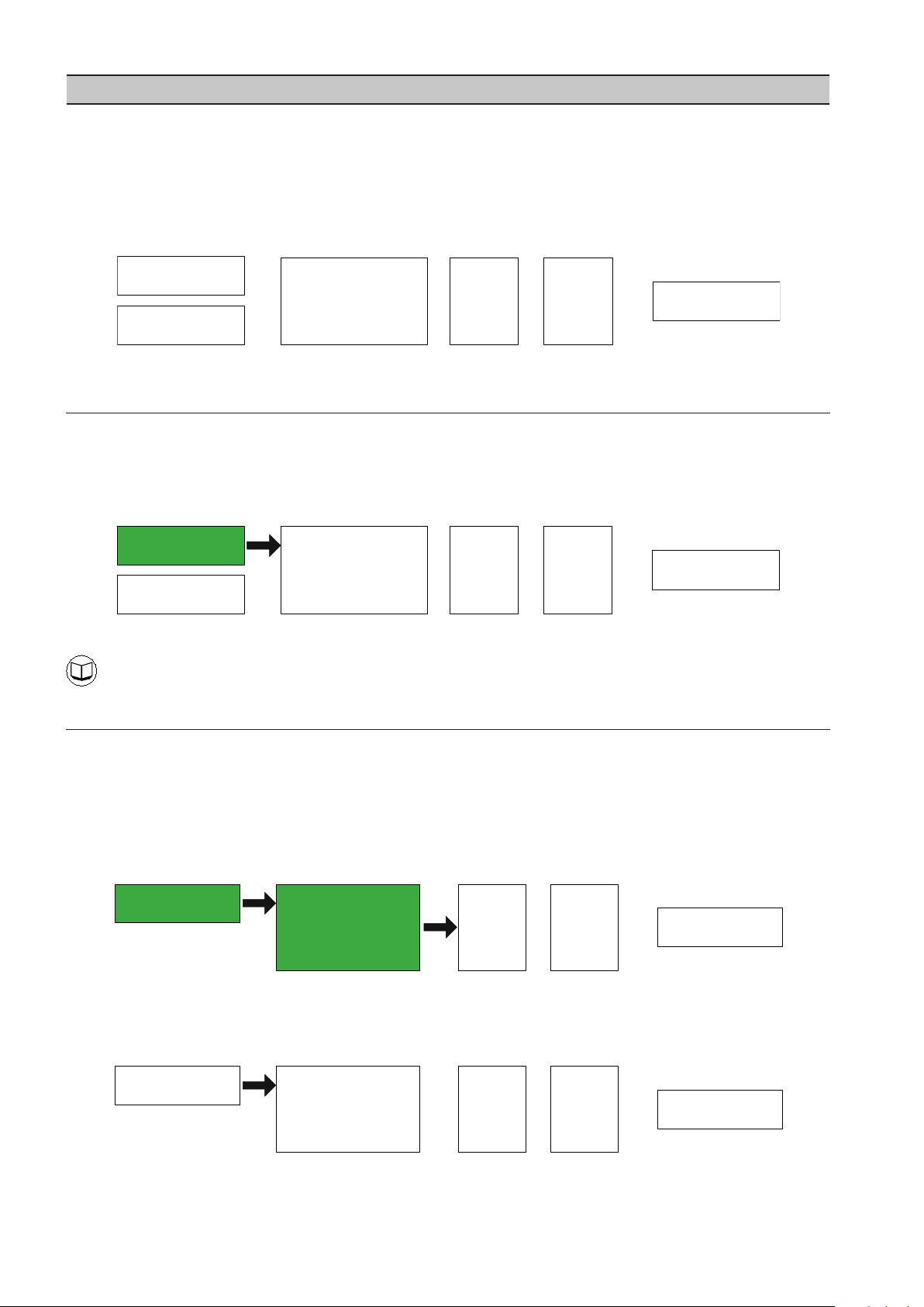
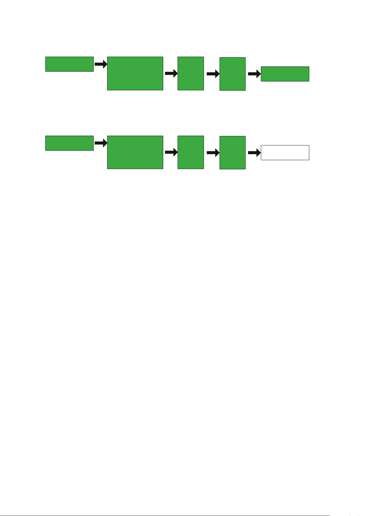
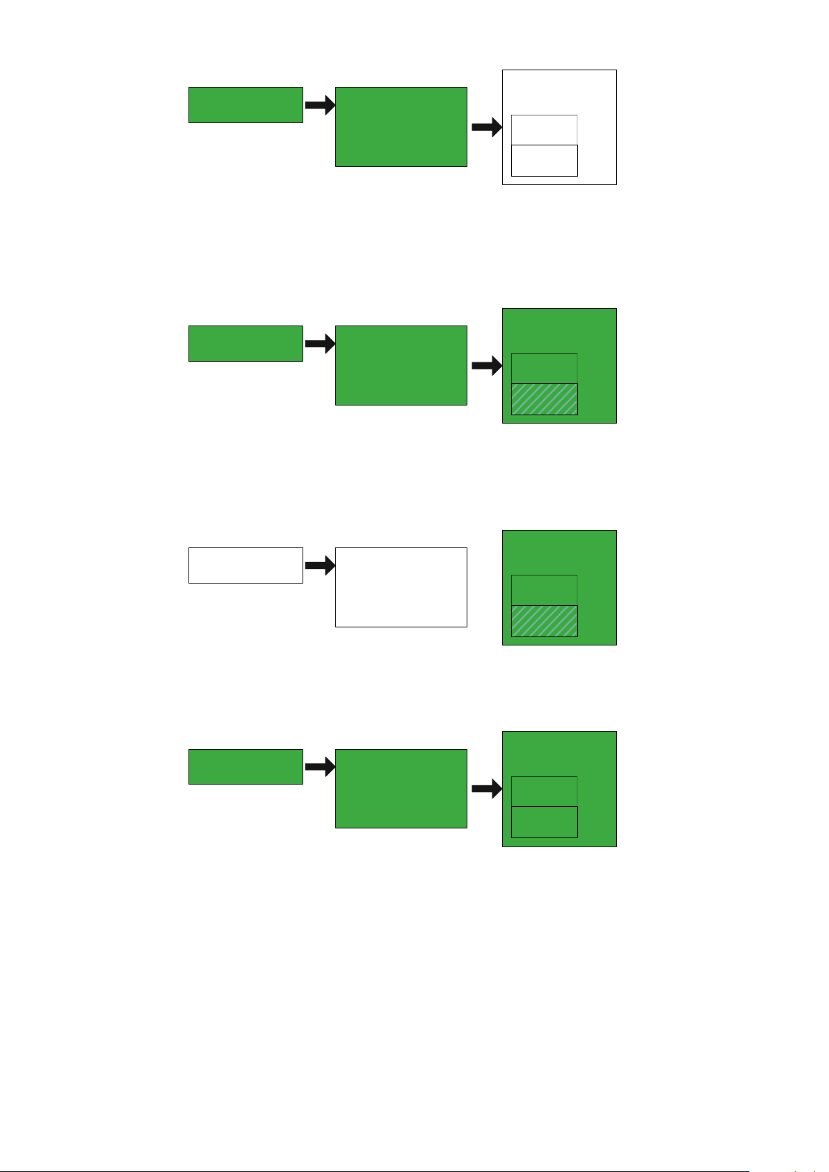
A virtual relay is a way for the user to create customized control for their air system using predened status registers in
the various X8I system components. Virtual relays should be thought of as a series of conditions that must be satised
in order to turn the output from false to true. The standard virtual relay consists of 5 conditions: Input Functions, Logic
Functions, On Delay Time, O Delay Time, and the Virtual Relay Output State. Each condition can only have two values,
it is either True (equal to 1) or False (equal to 0). The relationship of the conditions is shown below and the diagram is
read from left to right. The conditions on the very left must be True before moving onto the next condition until the
virtual relay output state is reached.
FIGURE 2 VIRTUAL RELAY WITH ALL CONDITIONS FALSE
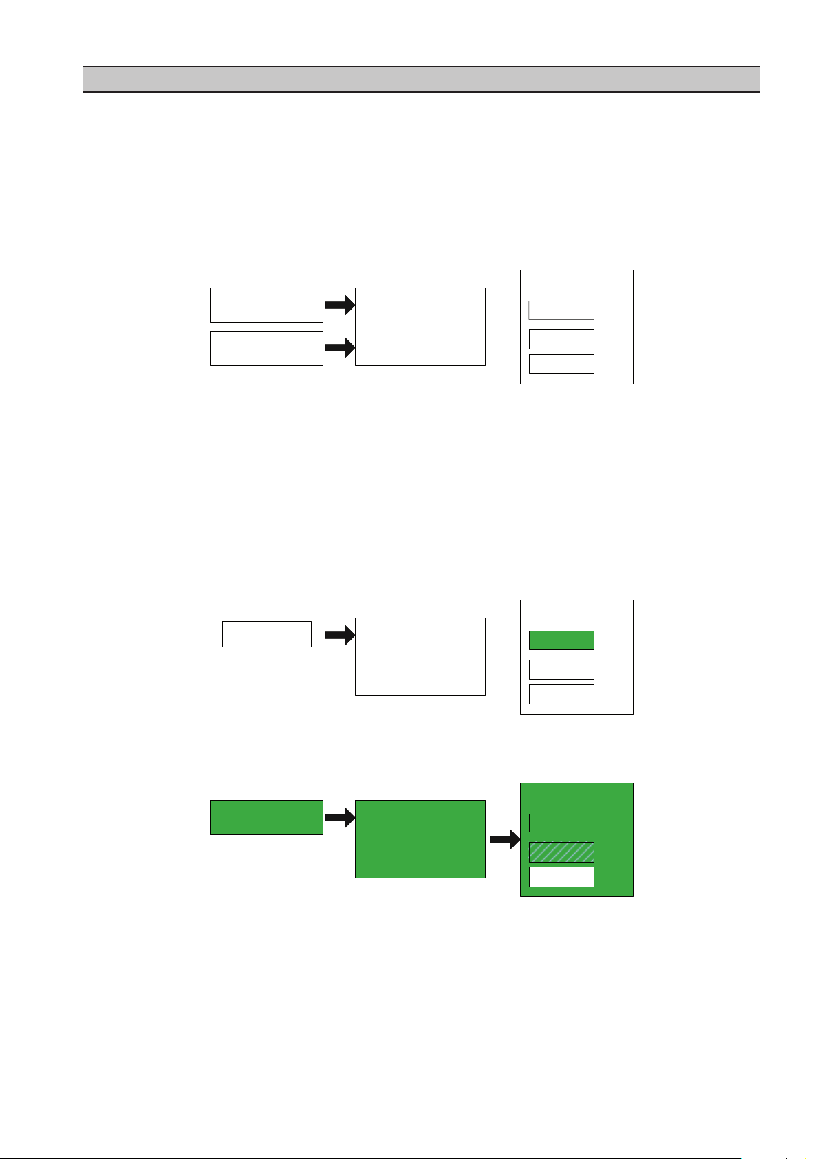
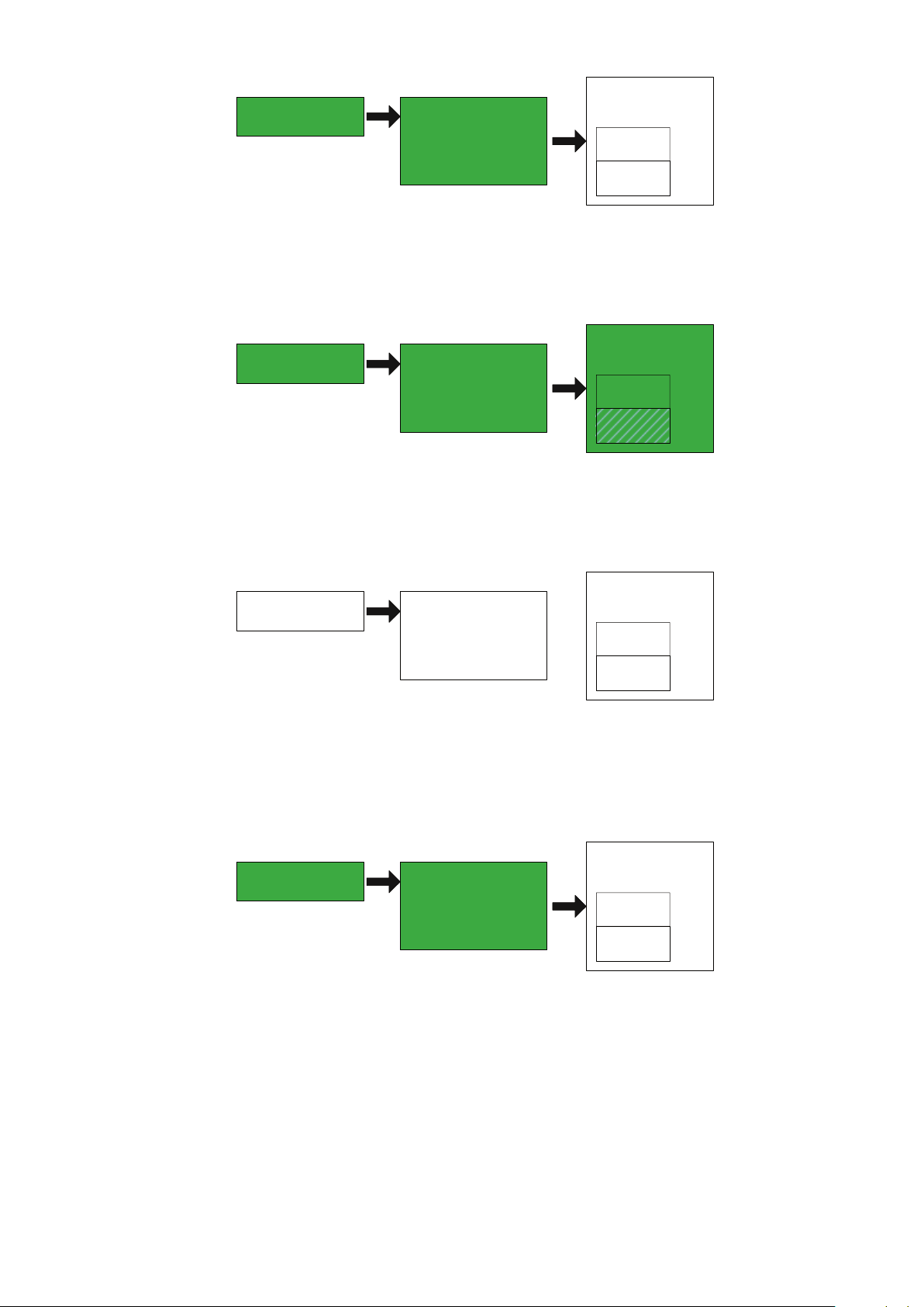
31. INPUT FUNCTIONS
An input function is the rst condition that is evaluated in a virtual relay. The input function is entered by the user and
can be the running condition of the X8I, whether or not Table #1 is active, compressor 1’s load state, or even if the X8I
is currently running in Energy Control mode. The input function will constantly be evaluated and when a True value
is encountered the next condition of the virtual relay will be evaluated. In all diagrams below a green box denotes a
condition that is evaluated as True.
FIGURE 3 INPUT FUNCTION 1 HAS BEEN EVALUATED AS TRUE
For a complete set of input functions please see 6.0 – Function Lists
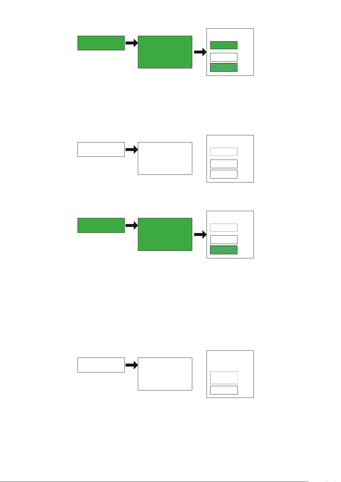
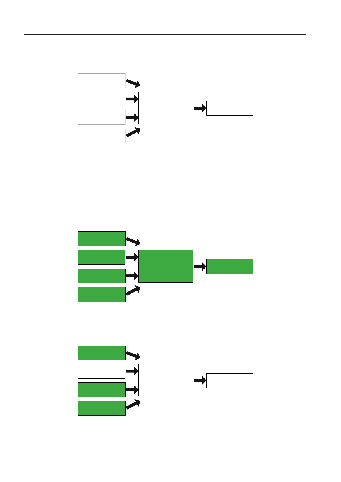
32. LOGIC FUNCTIONS
Each virtual relay can have up to two input functions assigned. Once the input functions have been dened the virtual
relay needs to decide how the relationship between the input functions will be evaluated. This next condition is
known as a Logic Function because it will perform a digital logic evaluation on the states of the input functions. The
available Logic Functions are F1, AND, OR, and XOR.
F1 – The logic function F1 is used when there is only one input function dened in the virtual relay. F1 evaluates the
state of the input function and if the input function is True then the logic function will also be evaluated as True. Please
note in the diagram below the Input Function 2 has been omitted.
FIGURE 4 LOGIC FUNCTION F1 HAS BEEN EVALUATED AS TRUE
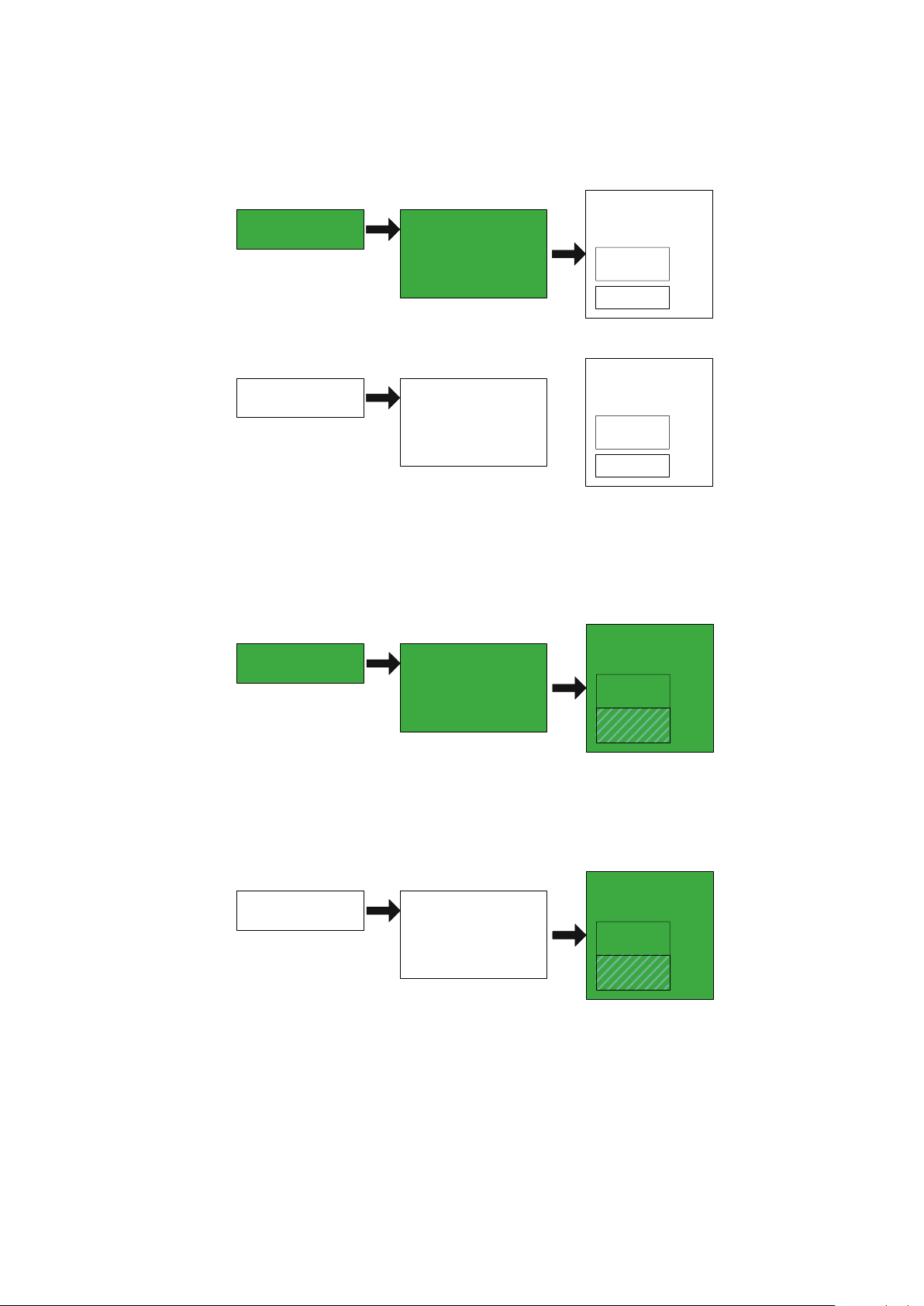
If input function 1 is evaluated as False, logic function F1 will also be evaluated as false and no further conditions will
be checked.
FIGURE 5 LOGIC FUNCTION F1 HAS BEEN EVALUATED AS FALSE
Page 5
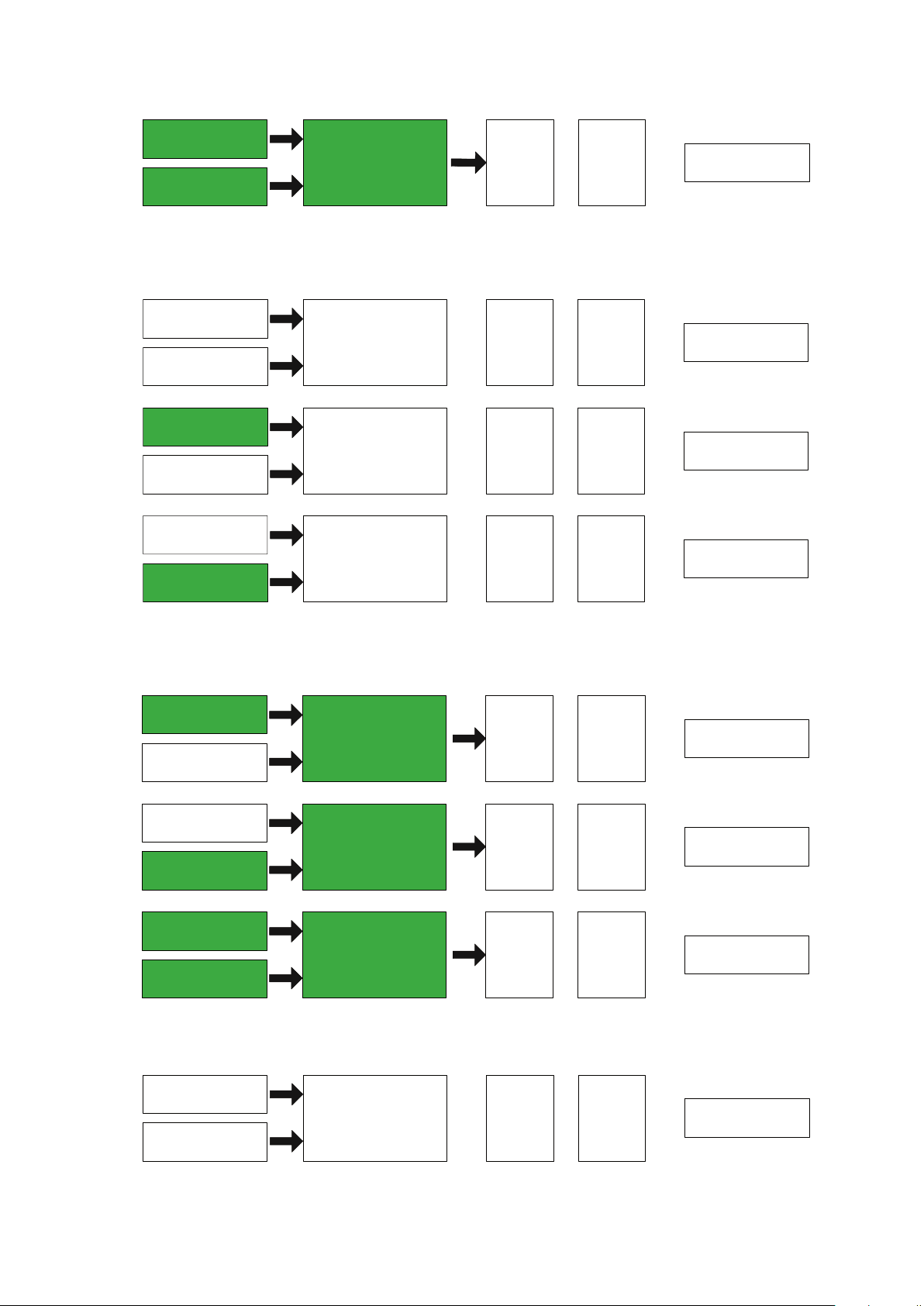
AND – The logic function AND is used with two input functions. The AND function is evaluated as True when both
Input Function 1
Input Function 2
Logic Function A ND
Virtual Relay
Output State
On Delay
Time
O Delay
Time
Input Function 1
Input Function 2
Logic Function AND
Virtual Relay
Output State
On Delay
Time
O Delay
Time
Input Function 1
Input Function 2
Logic Function AND
Virtual Relay
Output State
On Delay
Time
O Delay
Time
Input Function 1
Input Function 2
Logic Function AND
Virtual Relay
Output State
On Delay
Time
O Delay
Time
Input Function 1
Input Function 2
Logic Function OR
Virtual Relay
Output State
On Delay
Time
O Delay
Time
Input Function 1
Input Function 2
Logic Function OR
Virtual Relay
Output State
On Delay
Time
O Delay
Time
Input Function 1
Input Function 2
Logic Function OR
Virtual Relay
Output State
On Delay
Time
O Delay
Time
Input Function 1
Input Function 2
Logic Function OR
Virtual Relay
Output State
On Delay
Time
O Delay
Time
input function 1 and 2 are evaluated as True.
FIGURE 6 LOGIC FUNCTION AND HAS BEEN EVALUATED AS TRUE
Any other combination of input function states is evaluated as false and no further virtual relay conditions will be
checked.
FIGURE 7 LOGIC FUNCTION AND HAS BEEN EVALUATED AS FALSE
OR – The logic function OR is used with two input functions. The OR function will be evaluated as True when at least
one input function is True. The OR function will also be evaluated as True if both input functions are True.
FIGURE 8 LOGIC FUNCTION OR HAS BEEN EVALUATED AS TRUE
If both input functions are evaluated as false the logic function OR will also be evaluated as false.
FIGURE 9 LOGIC FUNCTION OR HAS BEEN EVALUATED AS FALSE
5
Page 6
6
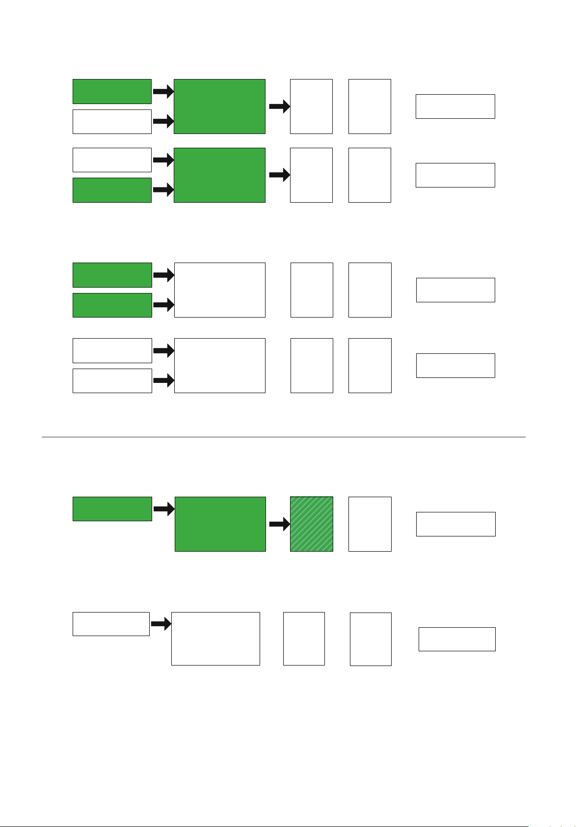
XOR – The logic function XOR (Exclusive OR) is used with two input functions. The XOR function will be evaluated as
Input Function 1
Input Function
2
Logic Function XOR
Virtual Relay
Output State
On Delay
Time
O Delay
Time
Input Function 1
Input Function 2
Logic Function XOR
Virtual Relay
Output State
On Delay
Time
O Delay
Time
Input Function 1
Input Function 2
Logic Function XOR
Virtual Relay
Output State
On Delay
Time
O Delay
Time
Input Function 1
Input Function 2
Logic Function XOR
Virtual Relay
Output State
On Delay
Time
O Delay
Time
Input Function 1
Logic Function F 1
Virtual Relay
Output State
On Delay
Timer
(counting)
O Delay
Time
Input Function 1
Logic Function F1
Virtual Relay
Output State
On Delay
Timer
(Reset to
0)
O Delay
Time
True when one, and only one, input function is True.
FIGURE 10 LOGIC FUNCTION XOR HAS BEEN EVALUATED AS TRUE
If neither input function is evaluated True or both of the input functions are evaluated as True then the XOR logic
function is evaluated as False.
FIGURE 11 LOGIC FUNCTION XOR HAS BEEN EVALUATED AS FALSE
33. ONDELAY TIMER
Virtual relays also have the capability to be used as time delay relays. The same input function and logic function rules
described above apply, but a time factor can be added. In the case of an on-delay timer virtual relay the logic function
must remain True for a specied amount of time before the on-delay timer is evaluated as True. This time is congured
by the user and is based in seconds. The on-delay timer begins timing when the Logic Function is evaluated as True.
FIGURE 12 ONDELAY TIMER BEGINS TO COUNT
If at any point the logic function turns False the on-delay timer will stop timing and will reset to zero elapsed time. If
the logic function again turns True the on-delay timer will start over.
FIGURE 13 ONDELAY TIMER RESETS AS THE LOGIC FUNCTION HAS BEEN EVALUATED AS FALSE
Once the on-delay timer reaches the specied amount of time it is evaluated as True and the next condition in the
virtual relay can be evaluated.
Page 7
Input Function 1
Logic Function F1
Virtual Relay
Output State
On Delay
Timer
(Done )
O Delay
Time
FIGURE 14 ONDELAY TIMER HAS ELAPSED AND BEEN EVALUATED AS TRUE
Input Function 1
Logic Function F1
Virtual Relay
Output State
On Delay
Timer
(Set to 0)
O Delay
Timer
Input Function 1
Logic Function F1
Virtual Relay
Output State
On Delay
Timer
(Set to 0)
O Delay
Timer
(Counting)
Input Function 1
Logic Function F1
Virtual Relay
Output State
On Delay
Timer
(Set to 0)
O Delay
Timer
(Reset)
Input Function 1
Logic Function F 1
Virtual Relay
Output State
On Delay
Timer
(Set to 0)
O Delay
Timer
(Done)
Please note that 0 seconds is a valid value for the on-delay timer duration. If the on-delay timer duration is set to zero
the on-delay timer will be evaluated as True as soon as the Logic Function is evaluated as True.
34. OFFDELAY TIMER
There is also an o-delay timer which works in an opposite way of the on-delay timer. The o delay timer be evaluated
as True as long as the logic function and on-delay timer are evaluated as True.
FIGURE 15 OFFDELAY TIMER HAS BEEN EVALUATED AS TRUE
Once the logic function is evaluated as False the o-delay timer will begin to count for a specied duration. After the
specied duration the o-delay timer will be evaluated as False. This time is congured by the user and is based in
seconds. While the O-Delay Timer is counting down the virtual relay output state will be maintained.
FIGURE 16 OFFDELAY TIMER BEGINS TO COUNT DOWN
If at any point the logic function and on-delay timer turn True the o-delay timer will stop timing and will reset to zero
elapsed time. If the logic function and on-delay timer again turn False the o-delay timer will start over.
FIGURE 17 OFF DELAY TIMER RESETS AS THE LOGIC FUNCTION AND
ONDELAY TIMER HAVE BEEN EVALUATED AS TRUE
Once the o-delay timer reaches the specied amount of time it is evaluated as False and the next condition in the
virtual relay can be evaluated.
The characteristics described so far are all considered part of a standard virtual relay. A standard virtual relay will be
designated as r01 through r16 on a virtual relay equipped component.
35. VIRTUAL RELAY OUTPUT STATE
The Virtual Relay Output State is the nal output of the virtual relay logic. The Virtual Relay Output State can be
operated in two dierent logic modes, Normally Open (NO) and Normally Closed (NC). These logic modes determine
how the output state will behave when all conditions in the virtual relay are evaluated as True.
7
Page 8
8
When the virtual relay is set to operate in NO mode the virtual relay output state will be evaluated as False until all
Input Function 1
Logic Function F1
Virtual Relay
Output State
On Delay
Timer
(Set to 0)
O Delay
Timer
Input Function 1
Logic Function F1
Virtual Relay
Output State
On Delay
Timer
(Set to 0)
O Delay
Timer
conditions in the virtual relay are evaluated as True. Once all conditions are satised the output state will turn True.
This is the most common type of logic and is used in examples throughout the remainder of this manual.
FIGURE 18 NORMALLY OPEN VIRTUAL RELAY OUTPUT STATE EVALUATED AS TRUE
When the virtual relay is set to operate in NC mode the virtual relay output state will be evaluated as True until all
conditions in the virtual relay are evaluated as True. Once all conditions are satised the output state will turn False
and remain there until one of the conditions is evaluated as False.
FIGURE 19 NORMALLY CLOSED VIRTUAL RELAY EVALUATED AS FALSE
Changing the output state can be used to invert logic without changing any of the input functions. This allows for an
eective doubling of logic options.
Page 9
SECTION 4 SPECIALIZED VIRTUAL RELAYS
Input Function 1
Input Function 2
Logic Function (F 1,
AND, OR , XOR )
Virtual Relay
Output State
On Timer
O Timer
Start State
Input Function 1
Logic Function F1
Virtual Relay
Output State
On Timer
O Timer
Start State
Input Function 1
Logic Function F1
Virtual Relay
Output State
On Timer
O Timer
Start State
In addition to the standard virtual relays the automation component may be equipped with specialized virtual relays
with unique behaviors. The specialized virtual relays can generally be divided into two groups; virtual relays with
unique behavior on the Virtual Relay Output State, and virtual relays with unique, xed, input functions.
41. VIRTUAL RELAYS WITH MODIFIED OUTPUT STATES
411. CYCLING TIMER VIRTUAL RELAYS
The cycling timer virtual relays are used to periodically cycle the Virtual Relay Output State between True and False
as long as all of its conditions are met. The conditions for the cycling timer virtual relay are: Input functions, logic
function, and the Virtual Relay Output State.
FIGURE 20 CYCLING TIMER VIRTUAL RELAY WITH ALL CONDITIONS FALSE
Input and Logic Functions
The cycling timer virtual relay input and logic functions are exactly the same as the standard virtual relay.
Virtual Relay Output State
The Virtual Relay Output State for a cycling timer virtual relay is “activated” when the logic function is evaluated as True.
Activated in this case does not necessarily mean the output state is evaluated as True as the output state has its own
internal conditions that must be evaluated: Start State, On Timer, and O Timer.
The Start State determines the initial True or False state of the Virtual Relay Output State when the logic function is
rst evaluated as True. If the Start State is set to True, when the logic function is rst evaluated as True the Virtual Relay
Output State will be evaluated as True and the On Timer will begin to count.
The on timer is a user adjustable setting that is either measured in seconds (rt1 and rt2) or hours (rt3). If the logic
function turns false before the on timer elapses the cycling timer virtual relay will return to the state shown in Figure 19.
After the on timer has elapsed the virtual relay output state will be evaluated as False even though the logic function is
still True. The o timer will now, however, begin to count.
FIGURE 21 VIRTUAL RELAY OUTPUT STATE WITH A START STATE
FIGURE 22 VIRTUAL RELAY OUTPUT STATE HAS BEEN EVALUATED
OF TRUE HAS BEEN EVALUATED FALSE
TRUE AND THE ON TIMER BEGINS COUNTING
9
Page 10
10
Input Function 1
Logic Function F1
Virtual Relay
Output State
On Timer
O Timer
Start State
FIGURE 23 THE ON TIMER ELAPSES, THE VIRTUAL RELAY OUTPUT STATE
Input Function 1
Logic Function F1
Virtual Relay
Output State
On Timer
O Timer
Start State
Input Function 1
Logic Function F1
Virtual Relay
Output State
On Timer
O Timer
Start State
Input Function 1
Logic Function F1
Virtual Relay
Output State
On Timer
Function
Select
HAS BEEN EVALUATED FALSE AND THE OFF TIMER BEGINS COUNTING
After the o timer has elapsed, the virtual relay output state will return to Figure 20 and this cycle will repeat until the
logic function is evaluated as False. The on timer and the o timer can never be active at the same time.
If the Start State is set to False, when the logic function is rst evaluated as True the Virtual Relay Output State will be
evaluated as False and the O Timer will begin to count.
FIGURE 24 VIRTUAL RELAY OUTPUT STATE WITH A START
STATE OF FALSE HAS BEEN EVALUATED FALSE
FIGURE 25 VIRTUAL RELAY OUTPUT STATE HAS BEEN EVALUATED
FALSE AND THE OFF TIMER BEGINS COUNTING
Once the o timer has elapsed the virtual relay output state turns True and the On timer begins counting. The cycling
timer virtual relay then continues to cycle as normal.
Cycling Timer Virtual Relays will be designated rt1, rt2, and rt3 on a virtual relay equipped component. Cycling Timer
Relays are not available on all components.
412. PULSE VIRTUAL RELAYS
The Pulse Virtual Relays are used to set the virtual relay output state to True for a xed period of time when the logic
function is rst evaluated as True. The conditions for the Pulse Virtual Relay are the Input Functions, Logic Function,
and Virtual Relay Output State.
FIGURE 26 PULSE VIRTUAL RELAY WITH ALL CONDITIONS FALSE
Input and Logic Functions
The Pulse Virtual Relay input and logic functions are exactly the same as the standard virtual relay.
Page 11
Virtual Relay Output State
Input Function 1
Logic Function F1
Virtual Relay
Output State
On Timer
Function
Select = 0
Input Function 1
Logic Function F1
Virtual Relay
Output State
On Timer
Function
Select = 0
Input Function 1
Logic Function F1
Virtual Relay
Output State
On Timer
Counting
Function
Select = 1
Input Function 1
Logic Function F1
Virtual Relay
Output State
On Timer
Counting
Function
Select = 1
The virtual relay output state for a pulse relay reacts to a True logic function evaluation dependent on how the
Function Select register is set by the user. There are four possible Function Select options that all behave dierently.
Function Select 0 – When the function select register is set to 0 the virtual relay output state will always remain False
regardless of whether the logic function is evaluated as True or False.
FIGURE 27 PULSE VIRTUAL RELAY WITH FUNCTION SELECT 0 NEVER
TURNS THE OUTPUT STATE TO TRUE
Function Select 1 – When the function select register is set to 1 the virtual relay output state will be evaluated as True
when the logic function is rst evaluated as True. The on timer will begin to count. The on timer is user specied and is
measured in seconds for rP1 and in minutes for rP2.
FIGURE 28 PULSE VIRTUAL RELAY WITH FUNCTION SELECT 1
TURNS THE OUTPUT STATE TRUE
When using Function Select 1, the virtual relay output state will always remain true while the on timer is counting. If
the logic function is evaluated as false it has no eect on the output and the output remains True.
FIGURE 29 OUTPUT REMAINS TRUE WHILE THE ON TIMER IS ACTIVE
If the logic function again turns true while the virtual relay output state is still true, there is no eect, the on timer
continues counting until it has completed its full duration. After the on timer has elapsed the virtual relay output state
will turn False and remain in the False state until the logic function is evaluated as False and subsequently evaluated as
True again.
11
Page 12
12
Input Function 1
Logic Function F1
Virtual Relay
Output State
On Timer
Done
Function
Select = 1
FIGURE 30 ON TIMER ELAPSES AND THE VIRTUAL RELAY
Input Function 1
Logic Function F1
Virtual Relay
Output State
On Timer
Counting
Function
Select = 2
Input Function 1
Logic Function F1
Virtual Relay
Output State
On Timer
Counting
Function
Select = 2
Input Function 1
Logic Function F1
Virtual Relay
Output State
On Timer
Reset
Function
Select = 2
OUTPUT STATE CHANGES TO FALSE
Function Select 2 – When the function select register is set to 2 the virtual relay output state will be evaluated as True
when the logic function is rst evaluated as True. The on timer will begin to count. The on timer is user specied and is
measured in seconds for rP1 and in minutes for rP2.
FIGURE 31 PULSE VIRTUAL RELAY WITH FUNCTION SELECT 2
TURNS THE OUTPUT STATE TRUE
When using Function Select 2, the virtual relay output state will always remain true while the on timer is counting. If
the logic function is evaluated as false it has no eect on the output and the output remains True.
FIGURE 32 OUTPUT REMAINS TRUE WHILE THE ON TIMER IS ACTIVE
If the logic function again turns true while the virtual relay output state is still true, the pulse will continue and the On
Timer is reset to zero and begins to count again.
FIGURE 33 LOGIC FUNCTION TRANSITIONS FROM FALSE
TO TRUE AND RESETS THE ON TIMER
After the on timer has elapsed the virtual relay output state will turn False and remain in the False state until the logic
function is evaluated as False and subsequently evaluated as True again.
Page 13
Input Function 1
Logic Function F1
Virtual Relay
Output State
On Timer
Done
Function
Select = 2
FIGURE 34 ON TIMER ELAPSES AND THE VIRTUAL RELAY
Input Function 1
Logic Function F1
Virtual Relay
Output State
On Timer
Counting
Function
Select = 3
Input Function 1
Logic Function F1
Virtual Relay
Output State
On Timer
Reset
Function
Select = 3
Input Function 1
Logic Function F1
Virtual Relay
Output State
On Timer
Done
Function
Select = 3
OUTPUT STATE CHANGES TO FALSE
Function Select 3 - When the function select register is set to 3 the virtual relay output state will be evaluated as True
when the logic function is rst evaluated as True.
FIGURE 35 PULSE VIRTUAL RELAY WITH FUNCTION SELECT 2
TURNS THE OUTPUT STATE TRUE
When using Function Select 3, if the logic function turns False at any time, the Virtual Relay Output State will turn False
and the on timer will be reset.
FIGURE 36 LOGIC FUNCTION EVALUATED AS FALSE CAUSES
THE VIRTUAL RELAY OUTPUT STATE TO TURN FALSE
If the logic function again turns True the on timer will begin counting from 0 and the virtual relay output state will stay
True until the on timer has elapsed.
FIGURE 37 ON TIMER ELAPSES AND THE VIRTUAL RELAY OUTPUT
STATE CHANGES TO FALSE
Pulse Virtual Relays will be designated rP1, and rP2 on a virtual relay equipped component.
Pulse Virtual Relays are not available on all components.
13
Page 14
14
42. VIRTUAL RELAYS WITH FIXED INPUT FUNCTIONS
Compressor 2
Run State
Logic Function
(AND or OR)
Virtual Relay
Output State
Compressor 3
Run State
Compressor 1
Run State
Compressor X
Run State
Compressor 2
Run State
Logic Function
AND
Virtual Relay
Output State
Compressor 3
Run State
Compressor 1
Run State
Compressor X
Run State
Compressor 2
Run State
Logic Function
AND
Virtual Relay
Output State
Compressor 3
Run State
Compressor 1
Run State
Compressor X
Run State
4.21. RUNNING VIRTUAL RELAY
The Running Virtual Relay allows the user to monitor the running states of any or all compressors in the system and to
use the status as an input function. The conditions that are used for the Running Virtual Relay are the compressor run
state, the logic function, and the virtual relay output state.
FIGURE 38 RUNNING VIRTUAL RELAY WITH ALL CONDITIONS FALSE
Input Functions
For the Running Virtual Relay the input functions are predened as the running state of each compressor. The
compressor running state is considered True when the compressor’s motor is determined to be operating by the
X8I either serially or electrically. The user selects the compressors that are to be used as input functions. Any or all
compressors may be used as input functions.
Logic Functions
The Running Virtual Relay utilizes the AND and OR logic functions. These logic functions operate in exactly the same
manner as they would in a normal virtual relay. For example, the AND logic function will only be evaluated as True if all
selected compressors’ run states are evaluated as True.
FIGURE 39 ALL COMPRESSORS ARE IN A TRUE RUN STATE WHICH
CAUSES THE LOGIC FUNCTION AND OUTPUT STATE TO BE EVALUATED TRUE
Any other combination of compressor run states will cause the logic function to be evaluated as false and therefore the
virtual relay output state will be evaluated as false.
FIGURE 40 COMPRESSOR 2’S RUN STATE HAS BEEN EVALUATED AS FALSE
WHICH CAUSES THE LOGIC FUNCTION TO BE EVALUATED AS FALSE
Page 15

The OR logic function will be evaluated as True if any or all compressors’ run states have been evaluated as True.
Compressor 2
Run State
Logic Function
OR
Virtual Relay
Output State
Compressor 3
Run State
Compressor 1
Run State
Compressor X
Run State
Compressor 2
Run State
Logic Function
OR
Virtual Relay
Output State
Compressor 3
Run State
Compressor 1
Run State
Compressor X
Run State
Compressor 2
Load State
Logic Function
(AND or OR)
Virtual Relay
Output State
Compressor 3
Load State
Compressor 1
Load State
Compressor X
Load State
FIGURE 41 COMPRESSOR 1’S RUN STATE IS TRUE WHICH CAUSES THE LOGIC
FUNCTION AND OUTPUT STATE TO TURN TRUE
The only input function state that would cause the OR function to be evaluated as False is when none of the
compressor run states are evaluated as True.
The Running Virtual Relay will be designated RF1 on a virtual relay equipped component.
422. LOADED VIRTUAL RELAY
The Loaded Virtual Relay allows the user to monitor the load states of any or all compressors in the system and to use
the status as an input function. The conditions that are used for the Loaded Virtual Relay are the compressor load state,
the logic function, and the virtual relay output state.
Input Functions
For the Loaded Virtual Relay the input functions are predened as the load state of each compressor. The compressor
load state is considered True when the compressor’s inlet valve is determined to be open by the X8I either serially or
electrically. The user selects the compressors that are to be used as input functions. Any or all compressors may be
used as input functions.
Logic Functions
The Loaded Virtual Relay utilizes the AND and OR logic functions. These logic functions operate in exactly the same
manner as they would in a normal virtual relay. For example, the AND logic function will only be evaluated as True if all
selected compressors’ load states are evaluated as True.
FIGURE 42 RUNNING VIRTUAL RELAY WITH OR LOGIC FUNCTION EVALUATED AS FALSE
FIGURE 43 LOADED VIRTUAL RELAY WITH ALL CONDITIONS FALSE
15
Page 16

16
Compressor 2
Load State
Logic Function
AND
Virtual Relay
Output State
Compressor 3
Load State
Compressor 1
Load State
Compressor X
Load State
FIGURE 44 ALL COMPRESSORS ARE IN A TRUE LOAD STATE WHICH CAUSES
Compressor 2
Load State
Logic Function
AND
Virtual Relay
Output State
Compressor 3
Load State
Compressor 1
Load State
Compressor X
Load State
Compressor 2
Load State
Logic Function
OR
Virtual Relay
Output State
Compressor 3
Load State
Compressor 1
Load State
Compressor X
Load State
Compressor 2
Load State
Logic Function
OR
Virtual Relay
Output State
Compressor 3
Load State
Compressor 1
Load State
Compressor X
Load State
THE LOGIC FUNCTION AND OUTPUT STATE TO BE EVALUATED TRUE
Any other combination of compressor load states will cause the logic function to be evaluated as false and therefore
the virtual relay output state will be evaluated as false.
FIGURE 45 COMPRESSOR 2’S LOAD STATE HAS BEEN EVALUATED AS FALSE
WHICH CAUSES THE LOGIC FUNCTION TO BE EVALUATED AS FALSE
The OR logic function will be evaluated as True if any or all compressors’ load states have been evaluated as True.
FIGURE 46 COMPRESSOR 1’S LOAD STATE IS TRUE WHICH CAUSES THE
LOGIC FUNCTION AND OUTPUT STATE TO TURN TRUE
The only input function state that would cause the OR function to be evaluated as False is when none of the
compressor load states are evaluated as True.
FIGURE 47 LOADED VIRTUAL RELAY WITH OR LOGIC FUNCTION EVALUATED AS FALSE
Page 17

The Loaded Virtual Relay will be designated LF1 on a virtual relay equipped component.
Compressor 2
Readiness State
Logic Function
(AND or OR)
Virtual Relay
Output State
Compressor 3
Readiness State
Compressor 1
Readiness State
Compressor X
Readiness State
Compressor 2
Readiness State
Logic Function
AND
Virtual Relay
Output State
Compressor 3
Readiness State
Compressor 1
Readiness State
Compressor X
Readiness State
423. AVAILABLE VIRTUAL RELAY
The Available Virtual Relay allows the user to monitor the readiness states of any or all compressors in the system and
to use the status as an input function. The conditions that are used for the Available Virtual Relay are the compressor
readiness state, the logic function, and the virtual relay output state.
FIGURE 48 AVAILABLE VIRTUAL RELAY WITH ALL CONDITIONS FALSE
Input Functions
For the Available Virtual Relay the input functions are predened as the readiness state of each compressor. The
compressor readiness state is considered True when compressor power is on and the compressor is in a state where
it will respond to X8I control, usually this means the compressor has been started locally. The user selects the
compressors that are to be used as input functions. Any or all compressors may be used as input functions.
Logic Functions
The Available Virtual Relay utilizes the AND and OR logic functions. Operate in an inverse logic manner for the
standard virtual relay AND and OR logic functions. For example, the AND logic function will only be evaluated as
false if all selected compressors’ readiness states are evaluated as True. For the Available Virtual Relay only, the AND
function acts as a logical NAND (Not AND)
Any other combination of compressor readiness states will cause the logic function to be evaluated as True and
therefore the virtual relay output state will be evaluated as True. This functionality allows the Available Virtual Relay to
determine when there is trouble with any or all compressors.
FIGURE 49 ALL COMPRESSORS ARE IN A TRUE READINESS STATE WHICH CAUSES
THE LOGIC FUNCTION AND OUTPUT STATE TO BE EVALUATED FALSE
17
Page 18

18
Compressor 2
Readiness State
Logic Function
AND
Virtual Relay
Output State
Compressor 3
Readiness State
Compressor 1
Readiness State
Compressor X
Readiness State
FIGURE 50 COMPRESSOR 2’S READINESS STATE HAS BEEN EVALUATED
Compressor 2
Readiness State
Logic Function
OR
Virtual Relay
Output State
Compressor 3
Readiness State
Compressor 1
Readiness State
Compressor X
Readiness State
Compressor 2
Readiness State
Logic Function
OR
Virtual Relay
Output State
Compressor 3
Readiness State
Compressor 1
Readiness State
Compressor X
Readiness State
Compressor 2
Readiness State
Logic Function
OR
Virtual Relay
Output State
Compressor 3
Readiness State
Compressor 1
Readiness State
Compressor X
Readiness State
AS FALSE WHICH CAUSES THE LOGIC FUNCTION TO BE EVALUATED AS FALSE
The OR logic function will be evaluated as True if all compressors’ readiness states are evaluated as False. For the
available virtual relay only the OR function operates as a logical NOR (Not OR) function. The OR function is used to
detect a situation when there are no compressors available for the X8I to use for system control.
FIGURE 51 ALL COMPRESSOR READINESS STATES ARE FALSE WHICH
CAUSES THE LOGIC FUNCTION AND OUTPUT STATE TO TURN TRUE
If any one or all compressor readiness states are evaluated as True the virtual relay output state will be evaluated as
False.
The Available Virtual Relay will be designated AF1 on a virtual relay equipped component.
FIGURE 52 AVAILABLE VIRTUAL RELAY WITH OR LOGIC FUNCTION EVALUATED AS FALSE
Page 19

SECTION 5 PHYSICAL I/O AND VIRTUAL RELAYS
Input Function 1
Input Function 2
Logic Function
(F1,AND, OR,
XOR)
Virtual Relay
Output State
On Delay
Time
O Delay
Time
Physical Relay
Output State
Signal Out
Certain components and accessory boxes have physical inputs and outputs that are available for use with virtual relay
automation. Digital Input statuses can be read an d used as an input function to a virtual relay while digital output
states can be read as an input function or connected to a virtual relay.
For certain X8I components the available physical relay outputs will be represented by the rst X virtual relay setup
menus. The physical relay will have the same conditions as a virtual relay: Input functions, Logic Function, On-delay
Timer, O-delay timer, and relay output state. The only dierence is that the physical relay will have contacts that will
match the virtual relay output state.
FIGURE 53 THE VIRTUAL RELAY HAS BEEN OUTPUT EVALUATED AS TRUE
SO THE PHYSICAL RELAY OUTPUT STATE MATCHES AND A SIGNAL IS SENT
Analog inputs can be used by setting up thresholds for Alarms, Trips, and Signals. Thresholds are triggered when the
analog value exceeds a threshold value. When the threshold is triggered a ag is turned true and these ags are what
can be used as an input function to the virtual relay.
Below is a list of virtual and physical relays that are included on automation components.
I/O Accessory Box
Physical I/O
4 Analog Inputs
•
8 Digital Inputs
•
6 Digital Outputs (Equivalent to Virtual Relays 1-6)
•
Virtual Relays
10 Virtual Relays
•
3 Cycling Timer Virtual Relays
•
2 Pulse Virtual Relays
•
1 Running Virtual Relay
•
1 Loaded Virtual Relay
•
1 Available Virtual Relay
•
19
Page 20

20
SECTION 6 CONFIGURING VIRTUAL RELAYS
A BBB C DD
Fn =
A
- - -
- - -
Fn =
-
BBB
- - -
Fn =
-
- - -
C
- -
Fn =
- - - -
-
DD
Fn =
Before attempting to program virtual relays to automate
an air system it is prudent to study the function list and
determine which functions you will need. Draw out the
logic that you intend to use so that any mistakes can
be minimized. Please note that while the parameters
for virtual relays are the same across the X8I product
line, the menu navigation will vary depending on which
component you are attempting to program. Be sure to
read the operator’s manual for the specic component
you are programming.
61. DEFINING AN INPUT FUNCTION
Input functions are common to all relays except for the
Running, Loaded, and Available virtual relays. Once you
have located the necessary input functions they must be
entered in the virtual relay using the following format:
Where the parameters are dened as follows:
- Species whether the input
function resides locally on the component you are
currently programming or is remote on the network. This
parameter is automatically selected based on the unit
where the input function resides and does not need to be
set by the user. The valid values for this parameter are:
types of functions are available to t your automation
needs. The available parameters are:
A – Alarm (warning) input functions, based on analog
thresholds
T – Trip (shutdown) or not available input functions,
based on analog thresholds
S – Signal input functions, based on analog
thresholds. Signals are informational only and do
not indicate a fault
R – Relay state, tells the output condition of a physical
or virtual relay.
F – Status Function, tells the status of various
conditions throughout the system.
Virtual relays can be used as input functions for other
virtual relays and will be located under the R menu.
For a complete set of input functions please see 10.x
– Function Lists
- Species the specic function
that is used for the virtual relay input function.
62. STANDARD VIRTUAL RELAYS R01
R16
L – The input function is local
R – The input function resides on another component
on the IR485 Network.
Please note that if the function is being transmitted
across the IR485 network there may be a delay between
the change in state of the input function and that change
in state being transmitted to the virtual relay.
Also note that in the case of a network failure or a failure
in the remote component the input function will be
unavailable and the virtual relay will return to a user
denable default state.
- Species the type of unit that the
input function resides on. This is the local unit, another
X8I, I/O box, or a compressor on the IR485 network. The
valid selections for this parameter are:
SYS – The X8I controller
B01 – I/O Box 1
B02 – I/O Box 2
C0X – Compressor X where X is 1 through 8
Compressors 1 through 8 can only be directly accessed if
the compressor is connected to the X8I using an ir-485 or
irV-485 gateway. Any compressor connected to the X8I
using an ir-PCB will have its status available via the SYS
unit type.
- Species the category of the
input function. The categories allow you to see what
The parameter list for a standard virtual relay is as
follows:
01 F1 Input Function #1
02 F2 Input Function #2
03 Fu Logic Function
04 On On Delay Time
05 OF O Delay Time
06 ST Normal State
07 CF RS485 Failure Response
F1 – Input Function 1
F2 – Input Function 2
F1 and F2 are selected using the methods shown in
dening an input function. Please note that it is not
necessary to dene two input functions to use a virtual
relay. If only one input function is used it must be entered
as F1. The default is no input function selected.
Fu – Logic Function
The logic function options are:
F1 – Only one input function is selected
And – Logical AND function
Or – Logical OR function
Eor – Logical Exclusive Or function (XOR)
Page 21

On – On-Delay Time
0
1
NO
NC
Of:
On:
Of:
On:
Of:
On:
Of:
On:
SS: 0 SS: 1
The on-delay time determines the length of time the logic
function must remain True before the virtual relay output
state changes to True. The on-delay time is measured in
seconds and defaults to zero.
Of – O-Delay Time
The o-delay time determines the length of time that a
logic function that is currently True would need to remain
False in order to return the virtual relay output state to
False. The o-delay time is measured in seconds and
defaults to zero.
ST – Normal State
The normal state denes what state virtual relay output
state is in when the logic function is evaluated as False.
The options are:
0 – Normally Open; the output state will remain False
when the logic function is True.
1 – Normally Closed; the output state will remain True
when the logic function is False.
CF – IR485 Failure State
CF denes the state the virtual relay output state will
revert to if there is a communication error on the IR485
network. CF will come into eect if either of the two
input functions suer a network failure. This will only
come happen when at least one of the input functions are
on a remote unit. The options for the CF are:
0 – The virtual relay output state will revert to False
1 – The virtual relay output state will revert to True
01 F1 Input Function #1
02 F2 Input Function #2
03 Fu Logic Function
04 On On Time
05 OF O Time
06 SS Start State
07 CF RS485 Failure Response
F1 – Input Function 1
F2 – Input Function 2
F1 and F2 are selected using the methods shown in
dening an input function. Please note that it is not
necessary to dene two input functions to use a virtual
relay. The default is no input function selected.
On – On Time
The on time determines how long the virtual relay output
state will remain in True state of the cycle when the logic
function is True. On rt1 and rt2 this value is measured in
seconds and has a valid range of 0 to 3600 seconds. The
default value is 0. On rt3 this value is measured in hours
and has a valid range of 0 to 168 hours.
Of – O Time
The o time determines how long the virtual relay
output state will remain in the False state of the cycle
when the Logic Function is True. On rt1 and rt2 this
value is measured in seconds and has a valid range of 0
to 3600 seconds. The default value is 0. On rt3 this value
is measured in hours and has a valid range of 0 to 168
hours.
SS – Start State
The Start State determines the initial state of the virtual
relay output function when the logic function rst turns
True. The valid options for this parameter are:
Please note that the virtual relay will not instantly revert
to the CF state, the IR485 network will rst need to time
out before the failure state is applied. The default state
for this parameter is 0.
63. CYCLING TIMER VIRTUAL RELAYS RT1,
RT2, RT3
The Cycling Timer Virtual Relay behaves a
bit dierently than the standard virtual relay in o-delay
or on-delay mode. The cycling timer will begin to cycle
the virtual relay output state between True and False
when the Logic Function is True. The timing of the True
and False virtual relay output state is user adjustable.
The parameter list for a cycling Timer Virtual Relay is as
follows:
0 – The virtual relay output state is initially in the False
position and will remain there until the o time
elapses
1 - The virtual relay output state is initially in the True
position and will remain there until the on time
elapses.
The default value for this parameter is 0.
CF – IR485 Failure State
CF denes the state the virtual relay output state will
revert to if there is a communication error on the IR485
network. CF will come into eect if either of the two
input functions suer a network failure. This will only
come happen when at least one of the input functions are
on a remote unit. The options for the CF are:
21
Page 22
22
0 – The virtual relay output state will revert to False
1 – The virtual relay output state will revert to True
Please note that the virtual relay will not instantly revert
to the CF state, the IR485 network will rst need to time
out before the failure state is applied. The default state
for this parameter is 0.
64. PULSE VIRTUAL RELAYS RP1, RP2, RP3,
AND RP4
The pulse virtual relays are used to turn
the virtual output state True for a specied period of time
in one single pulse. The pulse will only occur when the
Logic Function switches states. The parameters for the
Pulse Virtual Relay are as follows:
01 F1 Input Function #1
02 F2 Input Function #2
03 Fu Logic Function
04 On On Time
05 FS O Delay Time
06 CF RS485 Failure Response
changes from the False state to the True state. The
pulse will only occur on change of state and will
nish regardless of a later change from True to
False.
2 – The relay will pulse when the Logic Function
changes from the False state to the True state. If
another change of state from False to True occurs
during the pulse the time will be reset. The pulse
will nish regardless of a later change from True to
False.
3 – The relay will pulse when the Logic Function
changes from the False state to the True state. If
the Logic Function later changes from True to False
the pulse will end immediately.
CF – IR485 Failure State
CF denes the state the virtual relay output state will
revert to if there is a communication error on the IR485
network. CF will come into eect if either of the two
input functions suer a network failure. This will only
come happen when at least one of the input functions are
on a remote unit. The options for the CF are:
0 – The virtual relay output state will revert to False
1 – The virtual relay output state will revert to True
F1 – Input Function 1
F2 – Input Function 2
F1 and F2 are selected using the methods shown in
dening an input function. Please note that it is not
necessary to dene two input functions to use a virtual
relay. The default is no input function selected
Fu – Logic Function
The logic function options are:
F1 – Only one input function is selected
And – Logical AND function
Or – Logical OR function
Eor – Logical Exclusive Or function (XOR)
On – On Time
The on time determines how long the pulse will stay
active and hold the virtual relay output state in the True
position. The on time is user adjustable. rP1 is measured
in seconds and is adjustable from 0 to 3600 seconds. The
default setting is 0. rp2 is measured in minutes and is
adjustable from 0 to 3600 minutes. The default setting is
0.
FS – Function Selection
Function select denes on which coil state change the
pulse will be activated. The options are:
0 – The relay is o and no pulse will occur
1 – The relay will pulse when the Logic Function
Please note that the virtual relay will not instantly revert
to the CF state, the IR485 network will rst need to time
out before the failure state is applied. The default state
for this parameter is 0.
65. RUNNING VIRTUAL RELAY RF1
The Running Virtual Relay is a
specialized virtual relay that has input functions already
dened. The input functions are the running states of the
compressors in the X8I system. The running states of the
compressors are determined by the compressors status
register, if connected serially, or the ir-PCB input if the
compressor is wired directly to the automation system.
The parameters used to set up the Running Virtual Relay
are as follows:
01 01 Compressor #1
02 02 Compressor #2
03 03 Compressor #3
to
08 08 Compressor #8
09 Fu Logic Function
01 through 08 – Compressor 1 through 8
Each compressor is selectable from the Running Virtual
Relay parameter list. The options for each compressor
are:
Page 23

0 – The compressor will not be monitored for its
running state, the compressor is ignored for
running virtual relay purposes
1 – The compressor will be monitored for running
state
Fu – Logic Function
The logic functions available for the Running Virtual Relay
are:
And – Logical AND function. All compressors must be
running for the Logic Function to be True.
And – Logical AND function. All compressors must be
loaded for the Logic Function to be True.
Or – Logical OR function. At least one compressor
must be loaded for the Logic Function to be True.
An Example:
01 0 Compressor #1
02 1
03 1
Compressor #2
Compressor #3
Or – Logical OR function. At least one compressor
must be running for the Logic Function to be True.
An example:
01 1
02 1
03 0 Compressor #3
Fu OR Logic Function = OR
The above example conguration set-up shows a system
consisting of three compressors where 1 and 2 have been
selected for monitoring. The logic function (OR) means
the Logic Function will be True if one, or both, of the
selected compressors are detected as running.
Compressor #1
Compressor #2
66. LOADED VIRTUAL RELAY LF1
The Loaded Virtual Relay is a
specialized virtual relay that has input functions already
dened. The input functions are the loaded states of the
compressors in the X8I system. The loaded states of the
compressors are determined by the compressors status
register, if connected serially, or the ir-PCB input if the
compressor is wired directly to the automation system.
The parameters used to set up the Loaded Virtual Relay
are as follows:
01 01 Compressor #1
02 02 Compressor #2
03 03 Compressor #3
to
08 08 Compressor #8
09 Fu Logic Function
01 through 08 – Compressor 1 through 8
Each compressor is selectable from the Loaded Virtual
Relay parameter list. The options for each compressor
are:
0 – The compressor will not be monitored for its load
state, the compressor is ignored for loaded virtual
relay purposes
1 – The compressor will be monitored for load state
Fu – Logic Function
The logic functions available for the Loaded Virtual Relay
are:
Fu AND Logic Function = AND
The above example conguration set-up shows a system
consisting of three compressors where 2 and 3 have been
selected for monitoring. The logic function (AND) means
the logic function will only be True if both of the selected
compressors are detected as being loaded.
67. AVAILABLE VIRTUAL RELAY AF1
The Available Virtual Relay is a
specialized virtual relay that has input functions already
dened. The input functions are the Available states of
the compressors in the X8I system. The Available states
of the compressors are determined by the compressors
status register, if connected serially, or the ir-PCB input
if the compressor is wired directly to the automation
system. A compressor is considered available if it is not
under X8I control and is not tripped.
The parameters used to set up the Available Virtual Relay
are as follows:
01 01 Compressor #1
02 02 Compressor #2
03 03 Compressor #3
to
08 08 Compressor #8
09 Fu Logic Function
01 through 08 – Compressor 1 through 8
Each compressor is selectable from the Available Virtual
Relay parameter list. The options for each compressor
are:
0 – The compressor will not be monitored for its
availability state, the compressor is ignored for
available virtual relay purposes
1 – The compressor will be monitored for availablity
state
Fu – Logic Function
The logic functions available for the Available Virtual
Relay are:
And – Logical AND function. All compressors must be
available for the Logic Function to be False.
Or – Logical OR function. At least one compressor
must be available for the Logic Function to be
False.
23
Page 24

24
An Example:
01 0 Compressor #1
02 1
03 1
04 0 Compressor #4
Fu AND Logic Function = AND
The above example conguration set-up shows a system consisting of four compressors where 2 and 3 have been
selected for monitoring. The logic function (AND) means the Logic Function will be False if ‘all’ of the selected
compressors are detected as being available; the output will be True if ‘any’ of the selected compressors becomes
unavailable.
Compressor #2
Compressor #3
Page 25

R
SYS F
- -
SECTION 7 FUNCTION LISTS
71. X8I FUNCTION LIST
711. STATUS FUNCTIONS
SA: System Alarm (Warning):
True: An alarm condition associated with the X8I
has been detected.
False: No alarm condition associated with the
X8I has been detected.
ST: System Trip (Shutdown):
True: An trip condition associated with the X8I
has been detected.
False: No trip condition associated with the X8I
has been detected.
SF: System Alarm (Warning) or Trip (Shutdown):
True: An alarm or a trip condition associated
with the X8I has been detected.
False: No alarm or trip condition associated with
the X8I has been detected.
CA: Compressor Alarm (Warning):
True: An alarm condition has been detected on
one or more compressors.
False: No compressors are reporting an alarm
condition.
CT: Compressor Trip (Shutdown):
True: A trip condition has been detected on one
or more compressors.
False: No compressors are reporting a trip
condition.
CF: Compressor Alarm (Warning) or Trip
(Shutdown):
True: An alarm or trip condition has been
detected on one or more compressors.
False: No compressors are reporting an alarm or
trip condition.
BA: I/O Box Alarm (Warning):
True: An alarm condition has been detected on
one or more I/O Boxes.
False: No I/O Boxes are reporting an alarm
condition.
BT: I/O Box Trip (Shutdown):
True: A trip condition has been detected on one
or more I/O Boxes.
False: No I/O Boxes are reporting a trip
condition.
BS: I/O Box Signal:
True: A signal condition has been detected on
one or more I/O Boxes.
False: No I/O Boxes are reporting a signal
condition.
BF: I/O Box Alarm (Warning) or Trip (Shutdown):
True: An alarm or trip condition has been
detected on one or more I/O Boxes.
False: No I/O Boxes are reporting an alarm or
trip condition.
LP: Low Pressure Alarm (Warning):
True: System Pressure is below the X8I minimum
pressure setpoint.
False: System Pressure is above the X8I
minimum pressure setpoint.
HP: High Pressure Alarm (Warning):
True: System pressure is above the X8I
maximum pressure setpoint.
False: System pressure is below the X8I
maximum pressure setpoint.
IC: Insucient Capacity Alarm (Warning):
True: There are no available compressors to
meet rising demand
False: There are available compressors to meet
any change in demand
RC: Restricted Capacity Alarm (Warning):
True: There are no available compressors
to meet rising demand and one or more
compressors are removed from sequence by the
user.
False: There are available compressors to meet
any change in demand.
T1: Table #1 Active:
True: Table #1 is the X8I’s currently selected
table.
False: Table #1 is not currently in use.
T2: Table #2 Active:
True: Table #2 is the X8I’s currently selected
table.
False: Table #2 is not currently in use.
T3: Table #3 Active:
25
Page 26

26
True: Table #3 is the X8I’s currently selected
R
SYS S
- -
R
SYS R
- -
table.
False: Table #3 is not currently in use.
T4: Table #4 Active:
True: Table #4 is the X8I’s currently selected
table.
False: Table #4 is not currently in use.
PF: Prell Active:
True: The X8I’s prell function is active.
False: The X8I’s prell function is inactive.
EC: Energy Control Mode Active:
True: The X8I’s sequencing algorithm is set to
Energy Control mode (ENER).
False: The X8I’s sequencing algorithm is set to
something other than ENER.
TM: Timer Rotation Mode Active:
True: The X8I’s sequencing algorithm is set to
Timer Rotation Mode (FILO).
False: The X8I’s sequencing algorithm is set to
something other than FILO.
EH: Equal Hours Mode Active:
True: The X8I’s sequencing algorithm is set to
Equal Hours Mode (EHR).
False: The X8I’s sequencing algorithm is set to
something other than EHR.
PB: Pressure Balancing Function Active
Not available in the X8I
RU: X8I Running
True: The X8I is currently operating in prell,
normal operation, or standby state.
False: The X8I is currently in the stopped or trip
(shutdown) state.
PS: Pressure Schedule Active:
True: The X8I’s pressure schedule function is
active.
False: The X8I’s pressure schedule function is
inactive.
ON: X8I Pressure Regulation Control Active:
True: The X8I is currently operating in the prell
or normal operation state.
False: The X8I is currently operating in the
standby, stopped or tripped (shutdown) state.
DP: Dierential Pressure Alarm (Warning):
True: A high dierential pressure between two
system pressure transducers has been detected.
False: No high dierential pressure has been
detected.
AO: Capacity Alarm Override Active:
True: The insucient capacity and restricted
capacity alarms have been disabled.
False: The insucient capacity and restricted
capacity alarms have been enabled.
NW: Network: IR485 data communications:
True: Network communications are functioning
normally.
False: Network communications have been
disrupted.
712. SIGNAL FUNCTIONS
D1: Digital Input #1:
True: Digital Input #1 is in a True condition
(Actual state depends on whether the input is
Normally Open or Normally Closed).
False: Digital Input #1 is in a False condition
(Actual state depends on whether the input is
Normally Open or Normally Closed).
713. RELAY FUNCTIONS
Where a virtual relay is associated with a real physical
relay output the state of the virtual relay is identical to the
output state of the real physical relay.
01: Output Status of Physical Relay #1:
True: Physical Relay #1 is in a True condition
(Actual output state depends on whether the
relay is Normally Open or Normally Closed).
False: Physical Relay #1 is in a False condition
(Actual output state depends on whether the
relay is Normally Open or Normally Closed).
02: Output Status of Physical Relay #2:
True: Physical Relay #2 is in a True condition
(Actual output state depends on whether the
relay is Normally Open or Normally Closed).
False: Physical Relay #2 is in a False condition
(Actual output state depends on whether the
relay is Normally Open or Normally Closed).
03: Output Status of Physical Relay #3:
True: Physical Relay #3 is in a True condition
(Actual output state depends on whether the
relay is Normally Open or Normally Closed).
False: Physical Relay #3 is in a False condition
(Actual output state depends on whether the
relay is Normally Open or Normally Closed).
04: Output Status of Virtual Relay #4:
Page 27

True: Virtual Relay #4 is in a True condition
R
C01 F
- -
(Actual output state depends on whether the
relay is Normally Open or Normally Closed).
False: Virtual Relay #4 is in a False condition
(Actual output state depends on whether the
relay is Normally Open or Normally Closed).
05: Output Status of Virtual Relay #5:
True: Virtual Relay #5 is in a True condition
(Actual output state depends on whether the
relay is Normally Open or Normally Closed).
False: Virtual Relay #5 is in a False condition
(Actual output state depends on whether the
relay is Normally Open or Normally Closed).
06: Output Status of Virtual Relay #6:
True: Virtual Relay #6 is in a True condition
(Actual output state depends on whether the
relay is Normally Open or Normally Closed).
False: Virtual Relay #6 is in a False condition
(Actual output state depends on whether the
relay is Normally Open or Normally Closed).
07: Output Status of Virtual Relay #7:
True: Virtual Relay #7 is in a True condition
(Actual output state depends on whether the
relay is Normally Open or Normally Closed).
False: Virtual Relay #7 is in a False condition
(Actual output state depends on whether the
relay is Normally Open or Normally Closed).
08: Output Status of Virtual Relay #8:
True: Virtual Relay #8 is in a True condition
(Actual output state depends on whether the
relay is Normally Open or Normally Closed).
False: Virtual Relay #8 is in a False condition
(Actual output state depends on whether the
relay is Normally Open or Normally Closed).
09: Output Status of Virtual Relay #9:
True: Virtual Relay #9 is in a True condition
(Actual output state depends on whether the
relay is Normally Open or Normally Closed).
False: Virtual Relay #9 is in a False condition
(Actual output state depends on whether the
relay is Normally Open or Normally Closed).
10: Output Status of Virtual Relay #10:
True: Virtual Relay #10 is in a True condition
(Actual output state depends on whether the
relay is Normally Open or Normally Closed).
False: Virtual Relay #10 is in a False condition
(Actual output state depends on whether the
relay is Normally Open or Normally Closed).
11: Output Status of Virtual Relay #11:
True: Virtual Relay #11 is in a True condition
(Actual output state depends on whether the
relay is Normally Open or Normally Closed).
False: Virtual Relay #11 is in a False condition
(Actual output state depends on whether the
relay is Normally Open or Normally Closed).
12: Output Status of Virtual Relay #12:
True: Virtual Relay #12 is in a True condition
(Actual output state depends on whether the
relay is Normally Open or Normally Closed).
False: Virtual Relay #12 is in a False condition
(Actual output state depends on whether the
relay is Normally Open or Normally Closed).
13: Output Status of Virtual Relay #13:
True: Virtual Relay #13 is in a True condition
(Actual output state depends on whether the
relay is Normally Open or Normally Closed).
False: Virtual Relay #13 is in a False condition
(Actual output state depends on whether the
relay is Normally Open or Normally Closed).
14: Output Status of Virtual Relay #14:
True: Virtual Relay #14 is in a True condition
(Actual output state depends on whether the
relay is Normally Open or Normally Closed).
False: Virtual Relay #14 is in a False condition
(Actual output state depends on whether the
relay is Normally Open or Normally Closed).
15: Output Status of Virtual Relay #15:
True: Virtual Relay #15 is in a True condition
(Actual output state depends on whether the
relay is Normally Open or Normally Closed).
False: Virtual Relay #15 is in a False condition
(Actual output state depends on whether the
relay is Normally Open or Normally Closed).
16: Output Status of Virtual Relay #16:
True: Virtual Relay #16 is in a True condition
(Actual output state depends on whether the
relay is Normally Open or Normally Closed).
False: Virtual Relay #16 is in a False condition
(Actual output state depends on whether the
relay is Normally Open or Normally Closed).
72. COMPRESSOR FUNCTION LIST
721. STATUS FUNCTIONS
C01: Compressor #1
to
C08: Compressor #8
RA: Compressor Available:
True: The compressor is in a starting, running, or
auto restart state.
False: The compressor is in an unpowered,
tripped, or locally stopped state.
27
Page 28

28
Rn: Compressor Running: (Clarify with CMC about
B0# A
- -
Auto-Restart)
True: The compressor is in a running (loaded or
unloaded) state.
False: The compressor is not in a running
(loaded or unloaded) state. This includes an
auto-restart condition.
Ld: Compressor Loaded:
True: The compressor’s inlet valve is open and
the compressor is producing air.
False: The compressor’s inlet valve is closed and
the compressor is not producing air.
AL: Compressor Alarm (Warning):
True: The compressor is reporting an alarm
condition.
False: The compressor is not reporting an alarm
condition.
Tr: Compressor Trip (Shutdown) or Unavailable:
True: The compressor is unavailable due to a trip
or local stop or unpowered condition.
False: The compressor is available and able to be
utilized.
Se: Service Maintenance Condition:
True: The ir-PCB Service Maintenance function
has been enabled and the compressor is out-ofservice.
False: The ir-PCB Service Maintenance function
has not been enabled.
GF: Compressor General Fault:
True: The compressor is reporting an Alarm
(Warning), Trip (Shutdown), Stopped, or Not
Available condition.
False: The compressor is not reporting an Alarm
(Warning), Trip (Shutdown), Stopped, or not
Available condition.
Ma: Compressor Maintenance Condition:
True: The compressor has been selected as out-
of-service for long term maintenance in the X8I
compressor maintenance menu.
False: The compressor has not been selected as
out-of-service for long term maintenance in the
X8I compressor maintenance menu.
NW: Network: IR485 data communications:
True: Network communications are functioning
normally.
False: Network communications have been
disrupted.
Note that the NW function is only valid for compressors
connected via an ir-485 or irV-485 gateway.
73. I/O BOX FUNCTIONS
731. INPUT ALARM WARNING FUNCTIONS
Monitors analog and/or digital I/O Box inputs that have
been set for Alarm (Warning) function.
B0# = The I/O Box ID; B01 to B02
= ‘L’ if the local I/O Box
•
= ‘R’ if another remote I/O Box
•
D1: Alarm (Warning): Digital Input #1:
True: Digital Input #1 is reporting an Alarm
(Warning) condition.
False: Digital Input #1 is not reporting an Alarm
(Warning) condition.
D2: Alarm (Warning): Digital Input #2:
True: Digital Input #2 is reporting an Alarm
(Warning) condition.
False: Digital Input #2 is not reporting an Alarm
(Warning) condition.
D3: Alarm (Warning): Digital Input #3:
True: Digital Input #3 is reporting an Alarm
(Warning) condition.
False: Digital Input #3 is not reporting an Alarm
(Warning) condition.
D4: Alarm (Warning): Digital Input #4:
True: Digital Input #4 is reporting an Alarm
(Warning) condition.
False: Digital Input #4 is not reporting an Alarm
(Warning) condition.
D5: Alarm (Warning): Digital Input #5:
True: Digital Input #5 is reporting an Alarm
(Warning) condition.
False: Digital Input #5 is not reporting an Alarm
(Warning) condition.
D6: Alarm (Warning): Digital Input #6:
True: Digital Input #6 is reporting an Alarm
(Warning) condition.
False: Digital Input #6 is not reporting an Alarm
(Warning) condition.
D7: Alarm (Warning): Digital Input #7:
True: Digital Input #7 is reporting an Alarm
(Warning) condition.
False: Digital Input #7 is not reporting an Alarm
(Warning) condition.
D8: Alarm (Warning): Digital Input #8:
True: Digital Input #8 is reporting an Alarm
(Warning) condition.
Page 29

False: Digital Input #8 is not reporting an Alarm
B0# T
- -
B0# S
- -
(Warning) condition.
A1: Alarm (Warning): Analog Input #1:
True: Analog Input #1’s Alarm (Warning)
threshold has been exceeded.
False: Analog Input #1’s Alarm (Warning)
threshold has not been exceeded.
A2: Alarm (Warning): Analog Input #2:
True: Analog Input #2’s Alarm (Warning)
threshold has been exceeded.
False: Analog Input #2’s Alarm (Warning)
threshold has not been exceeded.
A3: Alarm (Warning): Analog Input #3:
True: Analog Input #3’s Alarm (Warning)
threshold has been exceeded.
False: Analog Input #3’s Alarm (Warning)
threshold has not been exceeded.
A4: Alarm (Warning): Analog Input #4:
True: Analog Input #4’s Alarm (Warning)
threshold has been exceeded.
False: Analog Input #4’s Alarm (Warning)
threshold has not been exceeded.
732. INPUT TRIP SHUTDOWN FUNCTIONS
Monitors analog and/or digital I/O Box inputs that have
been set for Trip (Shutdown) function.
B0# = The I/O Box ID; B01 to B02
= ‘L’ if the local I/O Box
•
= ‘R’ if another remote I/O Box
•
D1: Trip (Shutdown): Digital Input #1:
True: Digital Input #1 is reporting a Trip
(Shutdown) condition.
False: Digital Input #1 is not reporting a Trip
(Shutdown) condition.
D2: Trip (Shutdown): Digital Input #2:
True: Digital Input #2 is reporting a Trip
(Shutdown) condition.
False: Digital Input #2 is not reporting a Trip
(Shutdown) condition.
D3: Trip (Shutdown): Digital Input #3:
True: Digital Input #3 is reporting a Trip
(Shutdown) condition.
False: Digital Input #3 is not reporting a Trip
(Shutdown) condition.
D4: Trip (Shutdown): Digital Input #4:
True: Digital Input #4 is reporting a Trip
(Shutdown) condition.
False: Digital Input #4 is not reporting a Trip
(Shutdown) condition.
D5: Trip (Shutdown): Digital Input #5:
True: Digital Input #5 is reporting a Trip
(Shutdown) condition.
False: Digital Input #5 is not reporting a Trip
(Shutdown) condition.
D6: Trip (Shutdown): Digital Input #6:
True: Digital Input #6 is reporting a Trip
(Shutdown) condition.
False: Digital Input #6 is not reporting a Trip
(Shutdown) condition.
D7: Trip (Shutdown): Digital Input #7:
True: Digital Input #7 is reporting a Trip
(Shutdown) condition.
False: Digital Input #7 is not reporting a Trip
(Shutdown) condition.
D8: Trip (Shutdown): Digital Input #8:
True: Digital Input #8 is reporting a Trip
(Shutdown) condition.
False: Digital Input #8 is not reporting a Trip
(Shutdown) condition.
A1: Trip (Shutdown): Analog Input #1:
True: Analog Input #1’s Trip (Shutdown)
threshold has been exceeded.
False: Analog Input #1’s Trip (Shutdown)
threshold has not been exceeded.
A2: Trip (Shutdown): Analog Input #2:
True: Analog Input #2’s Trip (Shutdown)
threshold has been exceeded.
False: Analog Input #2’s Trip (Shutdown)
threshold has not been exceeded.
A3: Trip (Shutdown): Analog Input #3:
True: Analog Input #3’s Trip (Shutdown)
threshold has been exceeded.
False: Analog Input #3’s Trip (Shutdown)
threshold has not been exceeded.
A4: Trip (Shutdown): Analog Input #4:
True: Analog Input #4’s Trip (Shutdown)
threshold has been exceeded.
False: Analog Input #4’s Trip (Shutdown)
threshold has not been exceeded.
733. INPUT SIGNAL S FUNCTIONS
Monitors analog and/or digital I/O Box inputs that have
been set for signal (S) function.
The ‘Signal’ function is intended for automation purposes
only and does not generate a fault condition or display
message.
29
Page 30

30
B0# = The I/O Box ID; B01 to B02
B0# R
- -
L
= ‘L’ if the local I/O Box
•
= ‘R’ if another remote I/O Box
•
D1: Signal (S): Digital Input #1:
True: Digital Input #1 is reporting a Signal (S)
condition.
False: Digital Input #1 is not reporting a Signal
(S) condition.
D2: Signal (S): Digital Input #2:
True: Digital Input #2 is reporting a Signal (S)
condition.
False: Digital Input #2 is not reporting a Signal
(S) condition.
D3: Signal (S): Digital Input #3:
True: Digital Input #3 is reporting a Signal (S)
condition.
False: Digital Input #3 is not reporting a Signal
(S) condition.
D4: Signal (S): Digital Input #4:
True: Digital Input #4 is reporting a Signal (S)
condition.
False: Digital Input #4 is not reporting a Signal
(S) condition.
D5: Signal (S): Digital Input #5:
True: Digital Input #5 is reporting a Signal (S)
condition.
False: Digital Input #5 is not reporting a Signal
(S) condition.
D6: Signal (S): Digital Input #6:
True: Digital Input #6 is reporting a Signal (S)
condition.
False: Digital Input #6 is not reporting a Signal
(S) condition.
D7: Signal (S): Digital Input #7:
True: Digital Input #7 is reporting a Signal (S)
condition.
False: Digital Input #7 is not reporting a Signal
(S) condition.
D8: Signal (S): Digital Input #8:
True: Digital Input #8 is reporting a Signal (S)
condition.
False: Digital Input #8 is not reporting a Signal
(S) condition.
A1: Signal (S): Analog Input #1:
True: Analog Input #1’s Signal (S) threshold has
been exceeded.
False: Analog Input #1’s Signal (S) threshold has
not been exceeded.
A2: Signal (S): Analog Input #2:
True: Analog Input #2’s Signal (S) threshold has
been exceeded.
False: Analog Input #2’s Signal (S) threshold has
not been exceeded.
A3: Signal (S): Analog Input #3:
True: Analog Input #3’s Signal (S) threshold has
been exceeded.
False: Analog Input #3’s Signal (S) threshold has
not been exceeded.
A4: Signal (S): Analog Input #4:
True: Analog Input #4’s Signal (S) threshold has
been exceeded.
False: Analog Input #4’s Signal (S) threshold has
not been exceeded.
734. RELAY FUNCTIONS
Available for local I/O Box only
B0# = The I/O Box ID; B01 to B02
R1: Output Status of Physical Relay #1:
True: Physical Relay #1 is in a True condition
(Actual output state depends on whether the
relay is Normally Open or Normally Closed).
False: Physical Relay #1 is in a False condition
(Actual output state depends on whether the
relay is Normally Open or Normally Closed).
R2: Output Status of Physical Relay #2:
True: Physical Relay #2 is in a True condition
(Actual output state depends on whether the
relay is Normally Open or Normally Closed).
False: Physical Relay #2 is in a False condition
(Actual output state depends on whether the
relay is Normally Open or Normally Closed).
R3: Output Status of Physical Relay #3:
True: Physical Relay #3 is in a True condition
(Actual output state depends on whether the
relay is Normally Open or Normally Closed).
False: Physical Relay #3 is in a False condition
(Actual output state depends on whether the
relay is Normally Open or Normally Closed).
R4: Output Status of Physical Relay #4:
True: Physical Relay #4 is in a True condition
(Actual output state depends on whether the
relay is Normally Open or Normally Closed).
False: Physical Relay #4 is in a False condition
(Actual output state depends on whether the
relay is Normally Open or Normally Closed).
R5: Output Status of Physical Relay #5:
Page 31

True: Physical Relay #5 is in a True condition
(Actual output state depends on whether the
relay is Normally Open or Normally Closed).
False: Physical Relay #5 is in a False condition
(Actual output state depends on whether the
relay is Normally Open or Normally Closed).
R6: Output Status of Physical Relay #6:
True: Physical Relay #6 is in a True condition
(Actual output state depends on whether the
relay is Normally Open or Normally Closed).
False: Physical Relay #6 is in a False condition
(Actual output state depends on whether the
relay is Normally Open or Normally Closed).
R7: Output Status of Virtual Relay #7:
True: Virtual Relay #7 is in a True condition
(Actual output state depends on whether the
relay is Normally Open or Normally Closed).
False: Virtual Relay #7 is in a False condition
(Actual output state depends on whether the
relay is Normally Open or Normally Closed).
R8: Output Status of Virtual Relay #7:
True: Virtual Relay #7 is in a True condition
(Actual output state depends on whether the
relay is Normally Open or Normally Closed).
False: Virtual Relay #7 is in a False condition
(Actual output state depends on whether the
relay is Normally Open or Normally Closed).
R9: Output Status of Virtual Relay #9:
True: Virtual Relay #9 is in a True condition
(Actual output state depends on whether the
relay is Normally Open or Normally Closed).
False: Virtual Relay #9 is in a False condition
(Actual output state depends on whether the
relay is Normally Open or Normally Closed).
10: Output Status of Virtual Relay #10:
True: Virtual Relay #10 is in a True condition
(Actual output state depends on whether the
relay is Normally Open or Normally Closed).
False: Virtual Relay #10 is in a False condition
(Actual output state depends on whether the
relay is Normally Open or Normally Closed).
11: Output Status of Virtual Relay #11:
True: Virtual Relay #11 is in a True condition
(Actual output state depends on whether the
relay is Normally Open or Normally Closed).
False: Virtual Relay #11 is in a False condition
(Actual output state depends on whether the
relay is Normally Open or Normally Closed).
12: Output Status of Virtual Relay #12:
True: Virtual Relay #12 is in a True condition
(Actual output state depends on whether the
relay is Normally Open or Normally Closed).
False: Virtual Relay #12 is in a False condition
(Actual output state depends on whether the
relay is Normally Open or Normally Closed).
13: Output Status of Virtual Relay #13:
True: Virtual Relay #13 is in a True condition
(Actual output state depends on whether the
relay is Normally Open or Normally Closed).
False: Virtual Relay #13 is in a False condition
(Actual output state depends on whether the
relay is Normally Open or Normally Closed).
14: Output Status of Virtual Relay #14:
True: Virtual Relay #14 is in a True condition
(Actual output state depends on whether the
relay is Normally Open or Normally Closed).
False: Virtual Relay #14 is in a False condition
(Actual output state depends on whether the
relay is Normally Open or Normally Closed).
15: Output Status of Virtual Relay #15:
True: Virtual Relay #15 is in a True condition
(Actual output state depends on whether the
relay is Normally Open or Normally Closed).
False: Virtual Relay #15 is in a False condition
(Actual output state depends on whether the
relay is Normally Open or Normally Closed).
16: Output Status of Virtual Relay #16:
True: Virtual Relay #8 is in a True condition
(Actual output state depends on whether the
relay is Normally Open or Normally Closed).
False: Virtual Relay #8 is in a False condition
(Actual output state depends on whether the
relay is Normally Open or Normally Closed).
T1: Cycling Timer Virtual Relay #1:
True: Cycling Timer Virtual Relay #1 output state
is True.
False: Cycling Timer Virtual Relay #1 output state
is False.
T2: Cycling Timer Virtual Relay #2:
True: Cycling Timer Virtual Relay #2 output state
is True.
False: Cycling Timer Virtual Relay #2 output state
is False.
T3: Cycling Timer Virtual Relay #3:
True: Cycling Timer Virtual Relay #3 output state
is True.
False: Cycling Timer Virtual Relay #3 output state
is False.
P1: Pulse Virtual Relay #1:
True: Pulse Virtual Relay #1 output state is True.
False: Pulse Virtual Relay #1 output state is False.
P2: Pulse Virtual Relay #2:
True: Pulse Virtual Relay #2 output state is True.
31
Page 32

32
False: Pulse Virtual Relay #2 output state is False.
B0# F
- -
RF: Running Virtual Relay:
True: Running Virtual Relay output state is True.
False: Running Virtual Relay output state is False.
LF: Loaded Virtual Relay:
True: Loaded Virtual Relay output state is True.
False: Loaded Virtual Relay output state is False.
AF: Available Virtual Relay:
True: Available Virtual Relay output state is True.
False: Available Virtual Relay output state is
False.
RB: Reset Button Function:
True: Reset button has been pressed within the
previous ve seconds and the I/O box is not in
menu mode.
False: Reset button has not been pressed within
the previous ve seconds.
735. STATUS FUNCTIONS
B0# = The I/O Box ID; B01 to B02
= ‘L’ if the local I/O Box
•
= ‘R’ if another remote I/O Box
•
AA: Analog Input Alarm (Warning):
True: The selected I/O Box is reporting an
Analog Input Alarm (Warning) threshold has
been exceeded.
False: The selected I/O Box is not reporting
an Analog Input Alarm (Warning) has been
exceeded.
AT: Analog Input Trip (Shutdown):
True: The selected I/O Box is reporting an
Analog Input Trip (Shutdown) threshold has
been exceeded.
False: The selected I/O Box is not reporting
an Analog Input Trip (Shutdown) has been
exceeded.
AS: Analog Input Signal (S):
True: The selected I/O Box is reporting an
Analog Input Signal (S) threshold has been
exceeded.
False: The selected I/O Box is not reporting
an Analog Input Signal (S) threshold has been
exceeded
AF: Analog Input Fault:
True: The selected I/O Box is reporting an
Analog Input Alarm (Warning) or Analog Input
Trip (Shutdown) threshold has been exceeded.
False: The selected I/O Box is not reporting an
Analog Input Alarm (Warning) or Analog Input
Trip (Shutdown) threshold has been exceeded..
DA: Digital Input Alarm (Warning):
True: The selected I/O Box is reporting a Digital
Input Alarm (Warning).
False: The selected I/O Box is not reporting a
Digital Input Alarm (Warning).
DT: Digital Input Trip (Shutdown):
True: The selected I/O Box is reporting a Digital
Input Trip (Shutdown).
False: The selected I/O Box is not reporting a
Digital Input Trip (Shutdown).
DS: Digital Input Signal (S):
True: The selected I/O Box is reporting a Digital
Input Alarm (Warning).
False: The selected I/O Box is not reporting a
Digital Input Alarm (Warning).
DF: Digital Input Fault:
True: The selected I/O Box is reporting a Digital
Input Alarm (Warning) or Trip (Shutdown).
False: The selected I/O Box is not reporting a
Digital Input Alarm (Warning) or Trip (shutdown).
GA: General Input Alarm (Warning):
True: The selected I/O Box is reporting any or
all analog and digital inputs are in an Alarm
(Warning) condition.
False: The selected I/O Box is reporting that
no analog or digital inputs are in an Alarm
(Warning) condition.
GT: General Input Trip (Shutdown):
True: The selected I/O Box is reporting any
or all analog and digital inputs are in a Trip
(Shutdown) condition.
False: The selected I/O Box is reporting that no
analog or digital inputs are in an Trip (Shutdown)
condition.
GS: General Input Signal (S):
True: The selected I/O Box is reporting any or
all analog and digital inputs are in a Signal (S)
condition.
False: The selected I/O Box is reporting that
no analog or digital inputs are in a Signal (S)
condition.
GF: General Input Fault:
True: The selected I/O Box is reporting any or
all analog and digital inputs are in an Alarm
(Warning) or Trip (Shutdown) condition.
False: The selected I/O Box is reporting that
no analog or digital inputs are in an Alarm
(Warning) or Trip (Shutdown) condition.
NW: Network: IR485 data communications:
True: Network communications are functioning
normally.
False: Network communications have been
disrupted.
1: Always on:
True: This function is always in the True state.
Page 33

SECTION 8 VIRTUAL RELAY EXAMPLES
X8I On Function
Logic Function F1
Virtual Relay
Output State
On Delay
Time = 0
O Delay
Time = 0
Physical Relay
Output State
X8I On Function
Logic Function F1
Virtual Relay
Output State
On Delay
Time = 0
O Delay
Time = 0
Physical Relay
Output State
Dryer Start
Signal
R1
81. I/O BOX DRYER CONTROL
A user’s air system consists of an X8I, and I/O Accessory Box, and two compressors. The compressors are piped into an
air dryer that currently has to be manually activated before the compressors can be started. The dried air is then stored
in a receiver tank for use in the facility. The user would like to automate the system so that the dryer is activated when
any compressors are going to be running.
In order to accomplish this, the user rst needs to map out the virtual relay needed. After looking at the X8I function
lists he notes that “ON” input function, which is evaluated as True when the X8I is in Prell or normal operation mode,
is exactly what he needs to trigger the dryer. Since there is only one input function for the virtual relay he knows that
his logic function will be F1. No on-delay or o-delay time is needed since instant response is desired. The dryer’s
start input is expecting to see a current ow in order to start the machine so the virtual relay output state is set to NO
(Normally Open).
FIGURE 54 WHEN THE X8I IS STOPPED OR IN STANDBY THE DRYER WILL NOT RECEIVE A SIGNAL
FIGURE 55 WHEN THE X8I IS IN PREFILL OR NORMAL OPERATION, THE DRYER WILL BE STARTED
With the virtual relay action planned out the user would then make sure that the signal to the dryer is correctly wired
to output R1 on the I/O box. Once the wiring is nished it is time to program the relay.
FIGURE 56 THE DRYER IS WIRED INTO RELAY 1 ON THE I/O BOX
Since the user is utilizing the physical output on the I/O Box directly he goes to screen R01 from the I/O Box user
interface using the normal menu navigation procedures. Since the control was already drawn out it is only a matter of
inputting the parameters as shown below.
R01:
01 F1 R SYS F On
02 F2 - - - -
03 Fu F1
04 On 0 sec
05 OF 0 sec
06 ST 0
07 CF 0
With relay R1 now set up for automation control there will be no need for a worker to physically start the dryer any
time the compressed air system is being utilized.
33
Page 34

34
82. I/O BOX ISOLATION VALVE CONTROL
X8I LP Function
Digital Input # 2
Logic Function OR
Virtual Relay
Output State
On Delay
Time = 0
O Delay
Time = 0
Physical Relay
Output State
Close Valve
Signal
X8I LP Function
Digital Input # 2
Logic Function OR
Virtual Relay
Output State
On Delay
Time = 0
O Delay
Time = 0
Physical Relay
Output State
Close Valve
Signal
X8I LP Function
Digital Input # 2
Logic Function OR
Virtual Relay
Output State
On Delay
Time = 0
O Delay
Time = 0
Physical Relay
Output State
Close Valve
Signal
X8I LP Function
Digital Input # 2
Logic Function OR
Virtual Relay
Output State
On Delay
Time = 0
O Delay
Time = 0
Physical Relay
Output State
D2
I/O Box
R1
A user’s air system consists of an X8I, and I/O Accessory Box, and two compressors. The compressors are piped into
a receiver tank for use in the facility. The facility’s air piping is separated into two distinct zones. One zone is a high
priority zone that absolutely needs stable air pressure to keep production moving. The second zone is a lower priority
zone that has a lesser need for compressed air. There is an isolation valve installed in the piping between the two
zones. Currently, the isolation valve is operated manually whenever a user notices that system pressure is decaying.
If this system pressure decay is not noticed quickly enough there could be impact to production with defective parts
being made. In order to decrease these incidents the user has installed an electronic isolation valve in the system and
would like to automate the valve to close o the non-essential zone whenever system pressure drops too low.
The user, however, would also like to be able to maintain the ability to isolate the lower priority zone manually.
Knowing that the requirements are for isolating the zone when a low pressure situation occurs or when the manual
isolation switch is closed, the user scans the X8I function list and notes that the LP (Low Pressure Alarm) function
could be used as one input function to the virtual relay. The low pressure alarm will turn true when system pressure
falls below the X8I’s minimum pressure (Pm) setpoint. The user also selects Digital Input #2 on the I/O box to be the
input for the manual isolation valve switch and sets the input to Signal (S) mode as shown in the I/O Box manual.
Since either input function should be able to trigger the isolation valve the user selects the OR logic function. The
isolation valve is expecting to see a current ow in order to isolate the zone so the virtual relay output state is set to NO
(Normally Open).
FIGURE 57 THE ISOLATION VALVE IS CLOSED IF ANY OF THESE VIRTUAL RELAY STATES OCCUR
FIGURE 58 THE ISOLATION VALVE REMAINS OPEN IF NEITHER INPUT FUNCTION IS TRUE
With the virtual relay action planned out the user would then make sure that the signal to the isolation valve is
correctly wired to output R1 on the I/O box and that the manual isolation switch is correctly wired into Digital Input #2
on the I/O Box. Once the wiring is nished it is time to program the relay.
FIGURE 59 THE VALVE IS WIRED INTO DIGITAL INPUT 2 AND
THE VALVE IS WIRED INTO RELAY 1 ON THE I/O BOX
Page 35

Since the user is utilizing the physical output on the I/O Box directly he goes to screen R01 from the I/O Box user
X8I ON Function
Logic Function F1
Virtual Relay
Output State
On Timer
O Timer
Start State
X8I ON Function
Logic Function F1
Virtual Relay
Output State
On Timer
O Timer
Start State
X8I ON Function
Logic Function F1
Virtual Relay
Output State
On Timer
O Timer
Start State
interface using the normal menu navigation procedures. Since the control was already drawn out it is only a matter of
inputting the parameters as shown below.
R01:
01 F1 R SYS F LP
02 F2 L B01 S D2
03 Fu OR
04 On 0 sec
05 OF 0 sec
06 ST 0
07 CF 0
If a low-pressure alarm occurs, or the remote manual zone isolation switch is activated, the isolation valve is energized
and the air system zone isolated.
83. I/O BOX CONDENSATE DRAIN VALVE CONTROL
A user’s air system consists of an X8I, and I/O Accessory Box, and two compressors. The compressors are piped into a
receiver tank for use in the facility. Attached to the compressors are condensate drain valves that need to be opened
periodically to rid the system of excess moisture. The user wants to synchronize and automate the opening of these
drain valves. The drain valves need to be opened for two seconds every two minutes.
After reading up on how to use virtual relay automation, the user discovers that the Cycling Timer Virtual Relay
provides exactly the functionality that he is looking for. He knows that condensate only builds up when the
compressors are running and that whenever the system is o the drain valves should remain closed. After scanning
the function list for the X8I he notes that the ON function will provide exactly the input function he needs. Since there
is only one input function the F1 logic function is chosen. The drain valves need to be opened for two seconds, which
becomes the On time, and will remain closed for two minutes, which becomes the O time. He decides that he wants
the drain valves to initially open when the X8I On function is rst evaluated as True.
FIGURE 60 THE X8I IS STOPPED OR IN STANDBY SO THE OUTPUT STATE REMAINS FALSE
FIGURE 61 THE X8I IS IN NORMAL OPERATION AND THE ON TIMER COUNTS FOR 2 SECONDS
FIGURE 62 THE ON TIMER IS DONE AND THE OFF TIMER COUNTS FOR TWO MINUTES
35
Page 36

36
With the Cycling Timer Virtual Relay logic drawn out the user now inputs the parameters into the rt1 menu on the I/O
Cycling Timer
Virtually Relay rt1
Logic Function F1
Virtual Relay
Output State
On Delay
Time = 0
O Delay
Time = 0
Physical Relay
Output State
Cycling Timer
Virtual Relay rt1
Logic Function F1
Virtual Relay
Output State
On Delay
Time = 0
O Delay
Time = 0
Physical Relay
Output State
Valve Open
Signal
Box user interface as shown below.
Rt1
01 F1 R SYS F On
02 F2 - - - -
03 Fu F1
04 On 2 sec
05 OF 120 sec
06 SS 1
07 CF 0
Now that the timing relay is correctly set up, the virtual relay output state needs to be associated with a physical relay
output that sends a signal to open the condensate valves. In order to program this, the user needs to use the output
state of the cycling timer virtual relay rt1 as an input function to physical relay R01. The cycling timer virtual relay
output state is the only input function to relay R01 so the logic function is again F1. All timer functions are taken care
of by the cycling timer, so the on-delay and o-delay timers are set to 0. The condensate drain valves open when a
current ow is detected across their input so the normal state for relay R01 is set to Normally Open (NO).
FIGURE 63 WHEN CYCLING TIMER VIRTUAL RELAY RT1 IS EVALUATED AS FALSE
THE CONDENSATE VALVE WILL NOT RECEIVE A SIGNAL AND REMAINS CLOSED
FIGURE 64 WHEN THE CYCLING TIMER VIRTUAL RELAY RT1 IS EVALUATED AS
TRUE THE CONDENSATE VALVE RECEIVES A SIGNAL AND OPENS
With the Virtual Relay logic drawn out the user now inputs the parameters into the R01 menu on the I/O Box user
interface as shown below.
R01:
01 F1 L B01 R T1
02 F2 - - - -
03 Fu F1
04 On 0 sec
05 OF 0 sec
06 ST 0
07 CF 0
With the virtual relay programming complete the user conrms that the wiring to the condensate drain valves is
correct and the system automation is now complete.
Page 37

R1
FIGURE 65 THE CONDENSATE DRAIN VALVES ARE WIRED INTO RELAY 1 ON THE I/O BOX
Compressor 3
Run State
Logic Function
OR
Virtual Relay
Output State
Compressor 4
Run State
Compressor 3
Run State
Logic Function
OR
Virtual Relay
Output State
Compressor 4
Run State
Compressor 3
Run State
Logic Function
OR
Virtual Relay
Output State
Compressor 4
Run State
Compressor 3
Run State
Logic Function
OR
Virtual Relay
Output State
Compressor 4
Run State
84. I/O BOX WATER PUMP CONTROL
A user’s air system consists of an X8I, an I/O Accessory Box, and four compressors. Compressors 1 and 2 are located in
an area adjacent to the X8I. Compressors 3 and 4 are located in a remote area and connected to the X8I using IR485
communications. Compressors 3 and 4 are water cooled; if one or both of the compressors are utilized a water cooling
pump must be operated. The user wants to automate the operation of the water cooling pump so that he doesn’t have
to manually start the pump before using either Compressor 3 or 4.
The user thinks that this is a good application for virtual relay automation and begins to scan the function list for input
functions that will allow him to achieve his automation goal. He also notes that the Running Virtual Relay function on
the I/O Box can be used to notify the system when compressor 3 or compressor 4 is running. For the Running Virtual
Relay’s input functions he selects compressors 3 and 4. Since the water pump needs to be running if either compressor
is turned on he chooses the OR logic function.
FIGURE 66 NEITHER COMPRESSOR 3 NOR 4 ARE RUNNING SO THE OUTPUT STATE IS FALSE
With the Running Virtual Relay logic drawn out the user now inputs the parameters into the RF1 menu on the I/O Box
user interface as shown below.
FIGURE 67 IF EITHER OR BOTH COMPRESSOR 4 ARE RUNNING THE OUTPUT STATE IS TRUE
37
Page 38

38
01 0 Compressor #1
I/O Box Running
Virtual Relay
X8I Running
Function
Logic Function AND
Virtual Relay
Output State
On Delay
Time = 0
O Delay
Time = 30
Physical Relay
Output State
I/O Box Running
Virtual Relay
X8 I Running
Function
Logic Function AND
Virtual Relay
Output State
On Delay
Time = 0
O Delay
Time = 30
Physical Relay
Output State
I/O Box Running
Virtual Relay
X8I Running
Function
Logic Function AND
Virtual Relay
Output State
On Delay
Time = 0
O Delay
Time = 30
Physical Relay
Output State
I/O Box Running
Virtual Relay
X8I Running
Function
Logic Function AND
Virtual Relay
Output State
On Delay
Time = 0
O Delay
Time = 30
Physical Relay
Output State
I / O Box Running
Virtual Relay
X 8 I Running
Function
Logic Function AND
Virtual Relay
Output State
On Delay
Time = 0
O Delay
Time
Counting
Physical Relay
Output State
I/O Box Running
Virtual Relay
X8I Running
Function
Logic Function AND
Virtual Relay
Output State
On Delay
Time = 0
O Delay
Time
Done
Physical Relay
Output State
02 0 Compressor #2
03 1
04 1
Compressor #3
Compressor #4
Fu OR Logic Function = OR
The Running Virtual Relay is now ready to be used as an input function for an associated physical relay, I/O Box relay
R01. The user, however, only wants the water pump to be automated when the X8I is in control of the air system, so
he chooses the X8I Ru (Running) function to be the second input function. Since both the Running Virtual Relay and
the Ru function need to be true for the water pump to be activated the AND logic function is selected. The user also
determines that the water pump needs to continue providing cooling water for 30 seconds after both compressors
3 and 4 are shut down. The o-delay timer is perfectly suited for this task and set for 30 seconds. The water pump is
turned on when a current is detected on its start switch so the virtual relay output state should be set to normally open
(NO).
FIGURE 68 VIRTUAL RELAY R01 OUTPUT STATE REMAINS FALSE
FIGURE 69 BOTH INPUT FUNCTIONS ARE EVALUATED AS TRUE AND THE WATER PUMP IS TURNED ON
If the logic function turns false the o-delay timer will remain true and begin counting to 30 seconds. Once the timer
elapses the virtual output state will turn False and therefore the Physical Relay output state will turn false and the water
pump is turned o.
FIGURE 70 THE OFFDELAY TIMER BEGINS TO COUNT
FIGURE 71 THE OFFDELAY TIMER ELAPSES AND THE OUTPUTS TURN FALSE
With the Virtual Relay logic drawn out the user now inputs the parameters into the R01 menu on the I/O Box user
interface as shown below.
Page 39

R01:
01 F1 L B01 R RF
02 F2 R SYS F Ru
03 Fu AND
04 On 0 sec
05 OF 30 sec
06 ST 0
07 CF 1
Note the system management unit ‘Ru’ function is used to monitor for system activity on RS485 communications.
The ‘CF’ item is enabled to force the output to switch ‘ON’ if communications are disrupted or lost.
With the virtual relay programming complete the user conrms that the wiring to the water pump is correct and the
system automation is now complete.
39
Page 40

40
Virtual Relay Automation
F1
F2
Fu
CF
ST
On
Of
R01
F1:
F1 / AND / OR / XOR
F2:
ST=0 ST=1
F1 AND OR XOR
0 1
0 1
t
t
On:
Of:
sec
sec
F1
F2
Fu
CF
ST
On
Of
R02
F1:
F1 / AND / OR / XOR
F2:
ST=0 ST=1
F1 AND OR XOR
0 1
0 1
t
t
On:
Of:
sec
sec
F1
F2
Fu
CF
ST
On
Of
R03
F1:
F1 / AND / OR / XOR
F2:
ST=0 ST=1
F1 AND OR XOR
0 1
0 1
t
t
On:
Of:
sec
sec
F1
F2
Fu
CF
ST
On
Of
R04
F1:
F1 / AND / OR / XOR
F2:
ST=0 ST=1
F1 AND OR XOR
0 1
0 1
t
t
On:
Of:
sec
sec
F1
F2
Fu
CF
ST
On
Of
R05
F1:
F1 / AND / OR / XOR
F2:
ST=0 ST=1
F1 AND OR XOR
0 1
0 1
t
t
On:
Of:
sec
sec
F1
F2
Fu
CF
ST
On
Of
R06
F1:
F1 / AND / OR / XOR
F2:
ST=0 ST=1
F1 AND OR XOR
0 1
0 1
t
t
On:
Of:
sec
sec
F1
F2
Fu
CF
ST
On
Of
R07
F1:
F1 / AND / OR / XOR
F2:
ST=0 ST=1
F1 AND OR XOR
0 1
0 1
t
t
On:
Of:
sec
sec
F1
F2
Fu
CF
ST
On
Of
R08
F1:
F1 / AND / OR / XOR
F2:
ST=0 ST=1
F1 AND OR XOR
0 1
0 1
t
t
On:
Of:
sec
sec
Page 41

F1
F2
Fu
CF
ST
On
Of
R09
F1:
F1 / AND / OR / XOR
F2:
ST=0 ST=1
F1 AND OR XOR
0 1
0 1
t
t
On:
Of:
sec
sec
F1
F2
Fu
CF
ST
On
Of
R10
F1:
F1 / AND / OR / XOR
F2:
ST=0 ST=1
F1 AND OR XOR
0 1
0 1
t
t
On:
Of:
sec
sec
F1
F2
Fu
CF
ST
On
Of
R11
F1:
F1 / AND / OR / XOR
F2:
ST=0 ST=1
F1 AND OR XOR
0 1
0 1
t
t
On:
Of:
sec
sec
F1
F2
Fu
CF
ST
On
Of
R12
F1:
F1 / AND / OR / XOR
F2:
ST=0 ST=1
F1 AND OR XOR
0 1
0 1
t
t
On:
Of:
sec
sec
F1
F2
Fu
CF
ST
On
Of
R13
F1:
F1 / AND / OR / XOR
F2:
ST=0 ST=1
F1 AND OR XOR
0 1
0 1
t
t
On:
Of:
sec
sec
F1
F2
Fu
CF
ST
On
Of
R14
F1:
F1 / AND / OR / XOR
F2:
ST=0 ST=1
F1 AND OR XOR
0 1
0 1
t
t
On:
Of:
sec
sec
F1
F2
Fu
CF
ST
On
Of
R15
F1:
F1 / AND / OR / XOR
F2:
ST=0 ST=1
F1 AND OR XOR
0 1
0 1
t
t
On:
Of:
sec
sec
F1
F2
Fu
CF
ST
On
Of
R16
F1:
F1 / AND / OR / XOR
F2:
ST=0 ST=1
F1 AND OR XOR
0 1
0 1
t
t
On:
Of:
sec
sec
Virtual Relay Automation
41
Page 42

42
F1
F2
Fu
CF
SS
On
Of
T01
F1:
F1 / AND / OR / XOR
F2:
F1 AND OR XOR
0 1
0 1
t
On:
Of:
sec
sec
t
1
0
t
SS:
SS:
F1
F2
Fu
CF
SS
On
Of
T02
F1:
F1 / AND / OR / XOR
F2:
F1 AND OR XOR
0 1
0 1
t
On:
Of:
min
min
t
1
0
t
SS:
SS:
F1
F2
Fu
CF
SS
On
Of
T03
F1:
F1 / AND / OR / XOR
F2:
F1 AND OR XOR
0 1
0 1
t
On:
Of:
hr
hr
t
1
0
t
SS:
SS:
F1
F2
Fu
CF
FS
On
P01
F1:
F1 / AND / OR / XOR
F2:
F1 AND OR XOR
0 1
0 1
t
On:
min
t
2 3
F1
F2
Fu
CF
FS
On
P01
F1:
F1 / AND / OR / XOR
F2:
F1 AND OR XOR
0 1
0 1
t
On:
min
t
2 3
F1
F2
Fu
CF
FS
On
P03
F1:
F1 / AND / OR / XOR
F2:
F1 AND OR XOR
0 1
0 1
t
On:
sec
t
2 3
F1
F2
Fu
CF
FS
On
P04
F1:
F1 / AND / OR / XOR
F2:
F1 AND OR XOR
0 1
0 1
t
On:
sec
t
2 3
Virtual Relay Automation
Page 43

Fu
RF
C01
f
AND OR
C02 C03 C04
C05 C06
C07
C08 C09 C10
C11 C12
Fu
LF
C01
f
AND OR
C02 C03 C04
C05 C06
C07
C08 C09 C10
C11 C12
Fu
AF
C01
f
AND OR
C02 C03 C04
C05 C06
C07
C08 C09 C10
C11 C12
Virtual Relay Automation
43
Page 44

LOOK WHAT INGERSOLL RAND CAN DO FOR YOU!
Ecient Field Service
We maintain a highly trained sta of technicians
to service your equipment for preventive
maintenance, or to assist you should emergencies
ever occur.
Complete Repair Service
Our trained technicians will repair or overhaul
your equipment to factory specications,
using only genuine Ingersoll Rand parts.
Special Engineering Service
We can help you identify and solve your problems
by evaluating your needs and recommending
the proper equipment to give your maximum
eciency.
Spare Parts
By stocking genuine Ingersoll Rand spare
parts, we can help you avoid costly delays
or substituting inferior parts. Using genuine
Ingersoll Rand parts on you Ingersoll
Rand equipment will help to keep even
older equipment running in good-as-new
Complete Stock of Equipment
We carry a complete line of Ingersoll Rand
equipment and accessories designed to meet
any compressed air application. We are backed
by Ingersoll Rand’s prompt factory shipment to
ensure you on-time delivery.
condition.
A SUBSTITUTE IS NOT A REPLACEMENT!
Ensure you get peak performance and longevity out of your Ingersoll Rand product by insisting on genuine Ingersoll
Rand replacement parts and maintenance kits. Not only are the replacement parts made to precise dimensions and OEM-
specied metallurgy, but each part is backed by the Ingersoll Rand warranty. Your local Customer Centre, Distributor, or
direct Ingersoll Rand salesperson will work with your to ensure you get the parts you need to do the job right. Equip your
machines with only the best Ingersoll Rand genuine parts.
NOTE: THE USE OF REPAIR PARTS OTHER THAN THOSE INCLUDED WITHIN THE INGERSOLL RAND COMPANY
APPROVED PARTS LIST MAY CREATE UNSAFE CONDITIONS OR MECHANICAL FAILURES OVER WHICH INGERSOLL
RAND COMPANY HAS NO CONTROL. INGERSOLL RAND COMPANY SHALL BEAR NO RESPONSIBILITY FOR
EQUIPMENT ON WHICH NON-APPROVED REPAIR PARTS ARE INSTALLED.
The manufacturer reserves the right to make changes or add improvements without notice and without incurring any
obligation to make such changes to products previously sold.
 Loading...