

Page 1

Ingersoll Rand
Instruction Manual
System Automation
ir-PCB
Before installing or starting this unit for the first
time, this manual should be studied carefully to
obtain a working knowledge of the unit and or the
duties to be performed while operating and
maintaining the unit.
RETAIN THIS MANUAL WITH UNIT. This Technical
manual contains IMPORTANT SAFETY DATA and
should be kept with the unit at all times.
More Than Air. Answers.
Online answers: http://www.air.irco.com
C.C.N. : 80444482
REV. : A
DATE : DECEMBER 2007
Page 2
SECTION 1 TABLE OF CONTENTS
Refer to Section Indicated
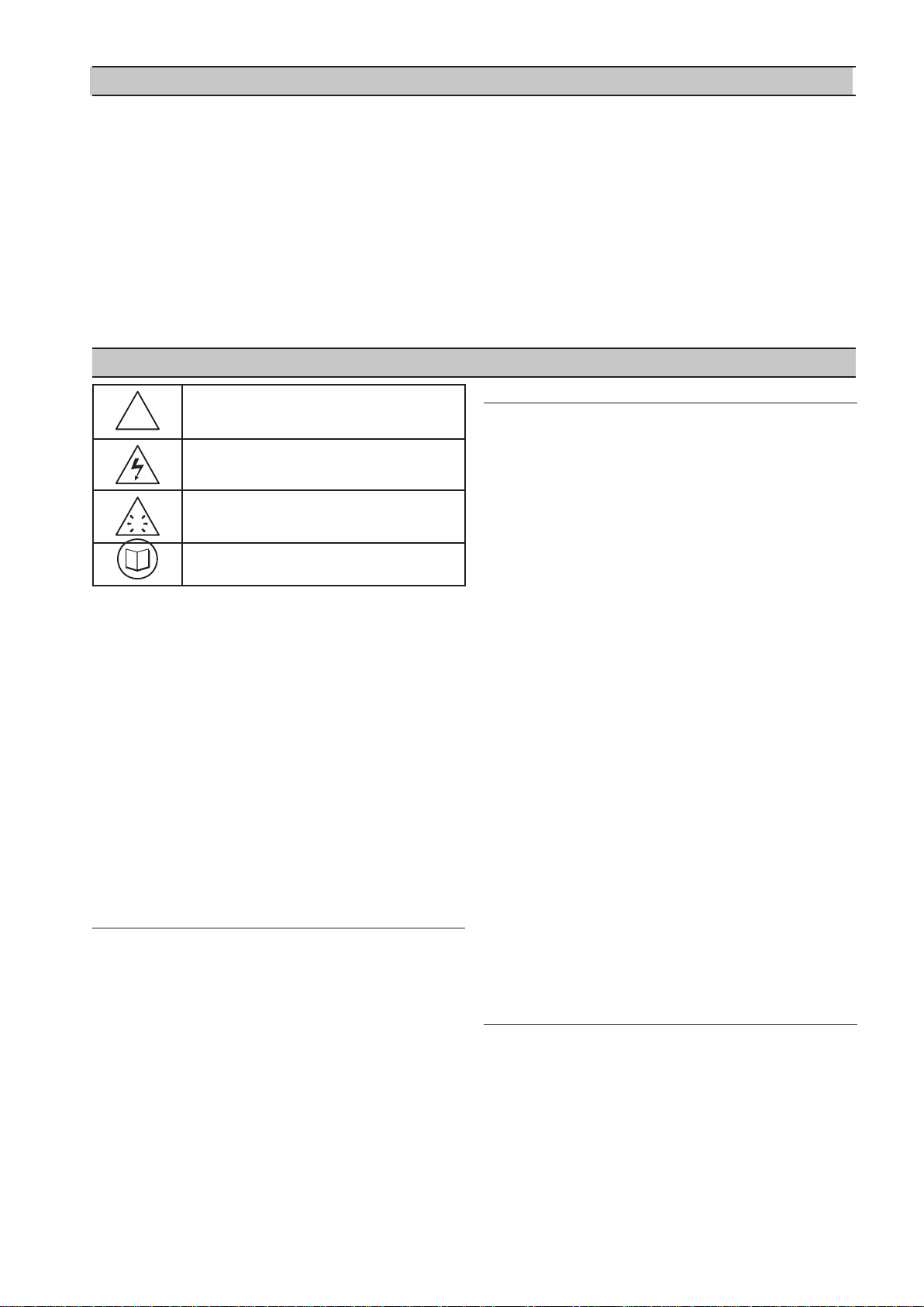
Note
Important or Caution, Safety
Section 1 - tABLe oF contentS .............................2
Section 2 - intRoDUction ...................................... 3
Section 3 -SAFety ....................................................... 3
INSTALLATION .............................................................................3
OPERATION
MAINTENANCE AND REPAIR
..................................................................................3
.................................................3
Section 4 - coMPReSSoR connection AnD
contRoL .........................................................................5
IR-PCB INTERFACE MODULE ................................................... 5
2
Page 3
stairs should be of grid or plate construction with
safety rails on all open sides.
Each air compressor in your system can be interfaced to the
X8I using the included IR-PCB interface modules. Any
compressor with an available control voltage of 12-250V
(either 50Hz or 60Hz) can be controlled by the X8I.
The interface module is mounted inside the compressor’s
starter panel and connected to the X8I by using a shielded
7-conductor cable or individual cables run through
grounded conduit.
Each air compressor must be equipped with an online/
offline pressure regulation system capable of accepting a
remote load/unload signal through a volt-free switching
contact or a single electro-mechanical pressure switch.
SECTION 2 INTRODUCTION
SECTION 3 SAFETY
OPERATION
!
WARNING : Risk of Danger
The ir-PCB must only be operated by
competent personnel under qualified supervision.
WARNING : Risk of Electric Shock
!
Before installing or operating the ir-PCB,
•
take time to carefully read all the instructions
contained in this manual, all compressor manuals,
and all manuals of any other peripheral devices that
may be installed or connected to the unit.
Electricity and compressed air have the potential to
•
cause severe personal injury or property damage.
The operator should use common sense and good
•
working practices while operating and maintaining
this system. All applicable codes should be strictly
adhered to.
Maintenance must be performed by adequately
•
qualified personnel that are equipped with the
proper tools.
WARNING : Risk of High Pressure
WARNING : Consult Manual
INSTALLATION
Installation work must only be carried out by a
•
competent person under qualified supervision.
A fused isolation switch must be fitted between the
•
main power supply and the ir-PCB .
The ir-PCB should be mounted in such a
•
location as to allow operational and maintenance
access without obstruction or hazard and to allow
clear visibility of indicators at all times.
If raised platforms are required to provide access
•
to the ir-PCB , they must not interfere with
normal operation or obstruct access. Platforms and
Never remove or tamper with safety devices, guards
or insulation materials fitted to the ir-PCB .
The ir-PCB must only be operated at
the supply voltage and frequency for which it is
designed.
When main power is switched on, lethal voltages are
present in the electrical circuits and extreme caution
must be exercised whenever it is necessary to carry
out any work on the unit.
Do not open access panels or touch electrical
components while voltage is applied unless it is
necessary for measurements, tests or adjustments.
Such work should be carried out only by a qualified
electrician equipped with the correct tools and
wearing appropriate protection against electrical
hazards.
All air compressors and/or other equipment
connected to the unit should have a warning sign
attached stating “THIS UNIT MAY START WITHOUT
WARNING” next to the display panel.
If an air compressor and/or other equipment
connected to the unit is to be started remotely,
attach two warning signs to the equipment stating
“THIS UNIT CAN BE STARTED REMOTELY”. Attach one
sign in a prominent location on the outside of the
equipment, and the other sign inside the equipment
control compartment.
MAINTENANCE AND REPAIR
Maintenance, repairs or modifications must only be
carried out by competent personnel under qualified
supervision.
If replacement parts are required, use only genuine
parts from the original equipment manufacturer, or
an alternative approved source.
3
Page 4

4
Carry out the following operations before opening or
•
removing any access panels or carrying out any work
on the ir-PCB :
Isolate the ir-PCB from the main electrical
i.
power supply. Lock the isolator in the “OFF”
position and remove the fuses.
Attach labels to the isolator switch and to the
ii.
unit stating “WORK IN PROGRESS - DO NOT APPLY
VOLTAGE”. Do not switch on electrical power
or attempt to start the ir-PCB if such a
warning label is attached.
Make sure that all instructions concerning operation
•
and maintenance are strictly followed and that
the complete unit, with all accessories and safety
devices, is kept in good working order.
The accuracy of sensor devices must be checked
•
on a regular basis. They must be calibrated when
acceptable tolerances are exceeded. Always ensure
any pressure within the compressed air system is
safely vented to atmosphere before attempting to
remove or install a sensor device.
The ir-PCB must only be cleaned with a damp
•
cloth, using mild detergents if necessary. Avoid the
use of any substances containing corrosive acids or
alkalis.
Do not paint the control faceplate or obscure any
•
indicators, controls, instructions or warnings.
Page 5

SECTION 4 COMPRESSOR CONNECTION AND CONTROL
IR-PCB INTERFACE MODULE
The IR-PCB is designed to interface a compressor with the
X9I using a 7-conductor shielded cable or individual wires
run through grounded conduit no greater than 330 feet
(100 meters) in length.
Each compressor in the system must be assigned a unique
identification number from 1 up to the number of
compressors in the system. The identification number
should be clearly indicated on each compressor for
operational reference.
For each compressor utilizing an IR-PCB, connection to the
X8I the signal wires must be made to the correct X9I
terminals for that compressor number. Compressor 1
should be wired to terminal X01 on the terminal PCB,
Compressor 2 should be wired to terminal X02 on the
terminal PCB, etc.
+VDC
VFD/fixed
C01
Load Enable
Load/Unload
NO
OUT
C
NC
C02
NO
IN
C
NC
LED 3
C04
ALARM
RUN
READY
C05
V
1
2
3
4
5
6
1
2
V
SEQ CONT
LOAD UNL
GND
C03
D11
D12
+20V
LED 5 V
LED 2 LOAD
LED 1 SEQ
LED 4
REA DY
RUN
IR-PCB Interface Module
The IR-PCB is a DIN rail mountable module designed to be
installed within the compressor starter enclosure.
Each air compressor must be equipped with a load/unload
regulation system and, if not regulated with a single
electro-mechanical pressure switch, have a facility for a
remote load/unload control with the ability to accept a voltfree switching contact input for remote load/unload. Each
air compressor must have Auto Restart capability.
V
For variable speed compressor(s) equipped with a
“variable/fixed” digital input function, install a 7-conductor
shielded cable from the IR-PCB to the X8I.
5
Page 6

Consult the air compressor manual or your air
compressor supplier/specialist for details before installing
the X8I.
Each air compressor must be equipped with an online/
offline pressure regulation system capable of accepting a
remote load/unload signal through a volt free switching
contact or a single electro-mechanical pressure switch.
The IR-PCB accepts a 12V to 250V input voltage detection
system and utilizes universal relay contact control outputs
(250V “CE” / 115V “UL” @ 5A maximum) integrated directly
into the circuits of an air compressor. The IR-PCB avoids the
need for additional relays or remote inputs. The IR-PCB also
acts as an electrical barrier between the compressor and the
X9I providing protection and voltage isolation.
Consult the X8I Interconnect and Application Guide
prior to the installation of the X8I and the IR-PCB to the air
compressor.
INPUT FUNCTIONS
The IR-PCB is fitted with a six-pin terminal, C04, for
compressor monitoring. The IR-PCB uses two inputs, Ready
and Run, to determine compressor status. An alarm input
can be used if compressor warning indication is available
and required. The alarm input is optional and is not
necessary for system operation.
READY INPUT
The ‘Ready’ connection is intended to indicate that the
compressor is in a “started” state, has no alarm condition
that has shut down the compressor, and is ready to respond
to X8I regulation without manual intervention.
The voltage to this input must de-energize when the
compressor is stopped and unavailable to produce air upon
a load signal, or the emergency stop button is pressed, or
when the compressor experiences a fault that prevents the
compressor from running.
When the compressor ready lamp or other control circuit is
energized, the IR-PCB will detect the voltage and signal the
X8I that the compressor is ready and available to load and
produce air when a load request signal is given.
The IR-PCB common input terminal must always be
connected to the neutral, common or 0V line of the applied
input voltage.
READY INPUT, ALTERNATIVE CONNECTION METHOD
In instances where a convenient voltage signal for a
compressor ready condition is not available, the “ready”
input can be connected directly to a constant compressor
control voltage (12V to 250Vac or dc). This will signal the
X8I that the compressor is ready and available at all times
when power is applied to the compressor. The X8I has a
built-in function to determine when a compressor is not
responding, or is in a shutdown condition, even if the
“ready” signal says otherwise. If the X8I requests a
compressor to run/load, but fails to detect a RUN signal
within 60 seconds, the X8I will regard the compressor as
“not ready” and indicate the compressor as not available. If
a RUN signal is reacquired at any time, the X8I will
automatically reset the compressor “not ready” condition
and re-establish control.
+Vac
F1
+V
READY LAMP
ALARM
RUN
C04
READY
0V
Typical Ready Input Wiring
The READY input will accept 12V to 250V ac (50/60Hz) or
dc.
Do not connect a voltage greater than 250Vac/dc to
this input.
This input must be connected to a circuit of the compressor
control system that will be energized when the compressor
is in a started (standby or running) condition. For example,
locate the circuit across the ready or operating lamp as
shown.
0Vac
READY
Alternative Ready Signal Connection
Never connect the “Ready” input positive voltage
connection directly to the output of a control system
transformer. Always connect after a fuse or circuit breaker.
If a normally closed contact of an emergency stop button is
included in the compressor power supply circuit, connect
after the emergency stop button contacts. This will instantly
indicate a compressor “not ready” condition if the
emergency stop button is activated.
6
Page 7

RUN INPUT
MAIN (L IN E ) CO N T A CTOR
0V
+V
READY
ALARM
RUN
C04
Run Signal Circuit
The RUN input will accept 12V to 250V AC (50/60Hz) only.
DC cannot be used.
Do not connect a voltage greater than 250V to this
input.
12V to 250Vac must be applied to the “run” terminals when
the compressor motor is running.
This input can be connected to the control terminals A1 and
A2 (coil) of the main starter contactor of the compressor.
When the compressor control system energizes the main
contactor, the IR-PCB will detect the voltage across the
contactor coil terminals and signal the X8I that the
compressor is running.
Alternatively, if the main contactor coil voltage is greater
than 250Vac, a contactor auxiliary switch can be used to
apply a suitable voltage to the “run” input terminals.
M A IN (LINE ) CO N TACTOR
+V
+V
AUXILIAR Y SW ITCH
0V
0V
The IR-PCB input common terminal must always be
connected to the neutral, common or 0V line of the applied
input voltage.
WARNING INPUT (OPTIONAL)
The IR-PCB is equipped with a warning input that can be
used to detect warning conditions.
An alarm that stops the compressor, and/or prevents
the compressor from running is determined from the “run”
and “ready” inputs. Warning detection is optional and is not
a requirement.
Alarm Lam p
+V
0V
Alarm Run Ready
C04
Warning Input Circuit
The warning input will accept 12V to 250V AC (50/60Hz) or
DC.
Do not connect a voltage greater than 250Vac/DC to
this input.
This input can be connected to the terminals of an alarm
lamp or other accessible part of the control circuit that is
energized when the compressor is in a warning condition.
If a warning condition is experienced the compressor
warning lamp, or warning circuit, will energize. The IR-PCB
will detect the voltage and signal the X8I that a warning has
occurred. If the compressor has no accessible warning
circuit, or this function is not required, the IR-PCB alarm
terminals can be ignored.
READY
ALARM
RUN
C04
Run Signal Circuit with Auxiliary Switch
In instances where a motor starter contactor is not available
or accessible, any part of a compressor control circ uit that
is energized when the compressor is running can be
monitored. For example: fan contactor or voltage signal to a
remote starter.
The IR-PCB input common terminal must always be
connected to the neutral, common or 0V line of the applied
input voltage.
7
Page 8

OUTPUT FUNCTIONS
The X8I will control the IR-PCB load/unload relay outputs
based on the active system load and unload pressure
setpoints. The IR-PCB load/unload relay contacts can be
used for compressor controllers that have electromechanical pressure switch load/unload regulation.
0V
+V
LOAD
SOLENOID
IR-PCB Internal Output Circuits
The C01 and C02 terminals of the IR-PCB are intended to
control load and unload regulation of the compressor.
PRESSURE SWITCH REGULATION
For air compressors fitted with an electro-mechanical
pressure switch, a six-pin terminal C02 has been provided
to enable connection to a pressure switch that has a twowire or three-wire connection.
When connected, the pressure switch ca n be switched in
and out of circuit automatically. If the X8I is stopped or
experiences a failure or loss of power, pressure control will
automatically revert back to the pressure switch and the
compressor will continue to operate in “local” mode.
The local pressure settings of all compressors in the
system should be set in a cascaded manner such that the
system will operate normally in the event of X8I
inoperability.
The NC (normally closed) and NO (normally open)
terminal references of the IR-PCB are related to internal
connection functions and should not be referenced to the
connections of a compressor pressure switch, which will
generally be in reverse order.
Lethal voltages may be present on the terminals of the
air compressor pressure switch. Isolate the air compressor
power supply before starting any work.
NC
C02
C
NC
NO
IN
C
NO
OUT
Two Wire Pressure Switch Connections
LOAD
SOLENOID
+V
RUN-ON
TIMER
C
C
NO
OUT
C02
NC
NC
NO
IN
0V
Three Wire Pressure Switch Connections
DIGITAL REGULATION CONTROL TERMINAL C01
A 4-pin connector, C01, has been provided for air
compressor controllers fitted with digital inputs allowing
remote pressure regulation control.
This terminal provides volt free contact closure, referenced
to a common terminal pin, for:
• Remote Load Enable (remote/local
pressure regulation control)
• Remote Load (remote load/unload)
• Remote Variable Speed Regulation Inhibit
(remote variable/fixed speed regulation
control)
The “remote load enable” function provides the facility to
change the compressor load regulation from internal
control to a remote switching source (local/remote).
V
The “remote variable/fixed” function provides for
multiple variable speed compressor regulation control on
variable speed compressor(s) equipped with this facility.
When using the “Variable/Fixed” function, the “V”
terminal of the IR-PCB must be connected to the
appropriate “V” terminal of the X8I (according to
compressor number) with an additional wire. Use a 7conductor shielded cable in this instance.
8
Page 9

Compressors that use electronic pressure detection
but are not equipped with a remote pressure control enable
feature will not automatically revert to local control if the
X8I is stopped or experiences a fault or loss of power.
The IR-PCB connection examples shown in this manual are
intended to provide a guide for the majority of compressor
control systems in use. Some compressors have variations
in operation and/or function; consult your compressor
supplier/specialist for advice.
VFD/Fixed
Load Enable
Load/Unload
+VDC
+VDC
VFD/Fixed
Load Enable
Load/Unload
ir-P C B
Load, Sequence, and VFD Connections
Compressor controller inputs common voltage may be
0V or +V.
The local/remote pressure regulation input and/or remote
load input logic of some electronic pressure sensor type
controllers are reversed. In this instance, the “pressure
switch” outputs (terminal C02) can be used to establish
alternative logic control connections.
For Example:
If the compressor controller “Local/Remote Pressure
Control” input is a normally open type (local when open,
remote when closed), but the “Remote Load” input is a
normally closed type (load when open), the IR-PCB pressure
switch terminal contacts can be used to achieve the correct
switching logic.
SERVICE MAINTENANCE SWITCH
The IR-PCB is equipped with a volt-free input (terminal
C05) that can be used to remove the compressor from X8I
control, without generating a fault condition, during shortterm maintenance or servicing periods.
1
C05
2
Service Maintenance Switch Circuit
When the “Service Maintenance Switch” input terminal pins
are connected together using a volt-free switching contact,
the X8I will indicate that the compressor is not available but
will not generate a warning, alarm, or shutdown condition.
The X8I will also remove the compressor from the sequence
strategy and substitute with an alternative available
compressor if necessary. When the “Service Maintenance
Switch” input circuit is open again, the compressor will
automatically be accepted back in to the sequence strategy
and will be utilized when next required.
The use of a “key switch” is recommended for this purpose
in order to prevent the switch contacts being inadvertently
left in the closed circuit condition after service maintenance
is complete.
DO NOT connect any external voltage source to the
pins of terminal C05.
OUT
C02
NO
C
NC
NO
IN
C
NC
Local/Remote
common
Remote Load
common
Alternate Logic
Examine the “i-PCB” internal output circuit diagram to
establish any desired switching logic that may differ from
normal practice.
Do not attempt to utilize “Digital Pressure Regulation
Control” (terminal C01) and the “Pressure Switch Control”
(terminal C02) output connections at the same time for
different products. These two output functions are
internally connected and a short circuit condition and/or
malfunction may result.
9
 Loading...