

Page 1

Ingersoll Rand
System Automation
I/O Accessory Box
Operator’s Manual
Before installing or starting this unit for the first
time, this manual should be studied carefully to
obtain a working knowledge of the unit and or the
duties to be performed while operating and
maintaining the unit.
RETAIN THIS MANUAL WITH UNIT. This Technical
manual contains IMPORTANT SAFETY DATA and
should be kept with the unit at all times.
More Than Air. Answers.
Online answers: http://air.ingersollrand.com
C.C.N. : 80444110
: A
REV.
DATE : DECEMBER 2008
Page 2

SECTION 1 TABLE OF CONTENTS
Section 1 - table of contentS .............................2
Section 2 - intRoDUction ......................................
Section 3 - Safety pRecaUtionS .........................
INSTALLATION .............................................................................3
OPERATION ...................................................................................3
MAINTENANCE AND REPAIR .................................................4
Section 4 - inStallation .........................................5
UNIT LOCATION ..........................................................................5
POWER SUPPLY ...........................................................................
RS485 NETWORK ........................................................................
I/O BOX ANALOG CONDITIONING MODULE................... 5
TO CHANGE AN ACM DEVICE: ............................................... 6
TO REMOVE AN ACM DEVICE: ............................................... 7
TO INSTALL AN ACM DEVICE: ...................................
ACM IDENTIFICATION ...............................................
6.5 OPERATION ............................................................
6.6 DIGITAL INPUT STATUS INDICATIONS ................
3
6.7 ANALOG INPUT DISPLAY .........................................
3
6.8 POWER FAILURE AUTORESTART ..........................
6.9 I/O BOX FAULT ..............................................................
6.10 SHUTDOWN FAULTS ...................................................
MANAGEMENT UNIT FAULT CODES .................................
Section 8 - paRtS liSt ..............................................20
Section 9 - technical Data ..................................
5
Section 10 - WiRing DiagRam ..............................
5
XPMTAC24 .................................................................................22
Refer to Section Indicated
7
7
Note
17
17
18
18
18
18
19
20
21
Section 5 - commiSSioning ....................................9
PHYSICAL CHECKS .....................................................................9
NETWORK ID ................................................................................
REFERENCE SYSTEM PRESSURE DISPLAY ......................... 9
I/O CONFIGURATION ................................................................9
VIRTUAL RELAY AUTOMATION .............................................9
Section 6 - DiSplay anD menU opeRation .....10
MENU NAVIGATION .................................................................10
MENU ITEMS AND SETTINGS ..............................................
MENU S01 CONFIGURATION ...............................
MENU D01 THROUGH D08 DIGITAL INPUTS .......
MENUS A01 THROUGH A04 ANALOG INPUTS ....
DIAGNOSTICS ............................................................................16
11
11
12
13
Section 7 - opeRation ............................................17
Important or Caution, Safety
9
6.1 USER INTERFACE .........................................................17
6.2 DISPLAY ..........................................................................
6.3 STATUS SYMBOLS ....................................................
6.4 INDICATORS ..................................................................
17
17
17
2
Page 3
SECTION 2 INTRODUCTION
1 2
A:
85%
Ingersoll Rand
IO
Ab.01
Ingersoll Rand
IO
Ab.02
!
!
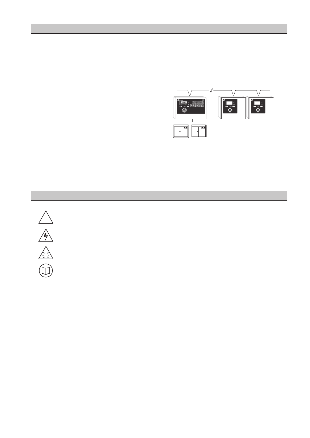
An I/O Box provides additional general purpose I/O
(input/output) for system enhancing monitoring
capabilities and for providing distributed system
automation via Virtual Relay.
More than one I/O Box can be installed in a system (up
to a maximum of 2 on an X8I). Each I/O Box features:
8 Digital Inputs
5 4-20 mA Analog Inputs (1 is a dedicated
pressure input)
6 Relay Outputs
Digital inputs can be used to monitor switching contact
devices. Each input can be set to act as an Alarm or
Trip input or used for Virtual Relay Automation. Digital
inputs can also be used for metering (for example m3,
ft3, kWh) providing an accumulative count of pulses
from a metering device.
Analog inputs can be used to monitor sensor
devices (for example: pressure, differential pressure,
temperature, dew point, flow, current, power, bearing
condition). Each input is equipped with adjustable high
or low level detection that can be used to activate an
Alarm or Trip or used for Virtual Relay Automation.
Relay outputs use the Virtual Relay Automation
technology and are totally configurable with dual
input logic functions. Relay functions can be assigned
utilizing any status or condition information available
on a system network from any compatible unit
connected to the network.
The I/O Box is designed to connect to a management
system using an industrial 2-wire RS485 data network,
with a total cable length up to 4000 ft (1219 m).
SECTION 3 SAFETY PRECAUTIONS
competent person under qualified supervision.
WARNING : Risk of Danger
WARNING : Risk of Electric Shock
WARNING : Risk of High Pressure
WARNING : Consult Manual
Before installing or operating the I/O Box, take time
•
to carefully read all the instructions contained in this
manual, all compressor manuals, and all manuals of
any other peripheral devices that may be installed or
connected to the unit.
Electricity and compressed air have the potential to
•
cause severe personal injury or property damage.
The operator should use common sense and good
•
working practices while operating and maintaining
this system. All applicable codes should be strictly
adhered to.
Maintenance must be performed by adequately
•
qualified personnel that are equipped with the
proper tools.
INSTALLATION
Installation work must only be carried out by a
•
A fused isolation switch must be fitted between the
•
main power supply and the I/O Box.
The I/O Box should be mounted in such a location
•
as to allow operational and maintenance access
without obstruction or hazard and to allow clear
visibility of indicators at all times.
If raised platforms are required to provide access
•
to the I/O Box they must not interfere with normal
operation or obstruct access. Platforms and stairs
should be of grid or plate construction with safety
rails on all open sides.
OPERATION
The I/O Box must only be operated by competent
•
personnel under qualified supervision.
Never remove or tamper with safety devices, guards
•
or insulation materials fitted to the I/O Box.
The I/O Box must only be operated at the supply
•
voltage and frequency for which it is designed.
When main power is switched on, lethal voltages are
•
present in the electrical circuits and extreme caution
must be exercised whenever it is necessary to carry
out any work on the unit.
Do not open access panels or touch electrical
•
components while voltage is applied unless it is
necessary for measurements, tests or adjustments.
3
Page 4

4
Such work should be carried out only by a qualified
electrician equipped with the correct tools and
wearing appropriate protection against electrical
hazards.
All air compressors and/or other equipment
•
connected to the unit should have a warning sign
attached stating “THIS UNIT MAY START WITHOUT
WARNING” next to the display panel.
If an air compressor and/or other equipment
•
connected to the unit is to be started remotely,
attach two warning signs to the equipment stating
“THIS UNIT CAN BE STARTED REMOTELY”. Attach
one sign in a prominent location on the outside
of the equipment, and the other sign inside the
equipment control compartment.
MAINTENANCE AND REPAIR
Maintenance, repairs or modifications must only
•
be carried out by competent personnel under
qualified supervision.
If replacement parts are required, use only genuine
•
parts from the original equipment manufacturer,
or an alternative approved source.
Carry out the following operations before opening
•
or removing any access panels or carrying out any
work on the I/O Box:
i. Isolate the I/O Box from the main electrical
power supply. Lock the isolator in the “OFF”
position and remove the fuses.
ii. Attach label to the isolator switch and to the
unit stating “WORK IN PROGRESS - DO NOT
APPLY VOLTAGE”. Do not switch on electrical
power or attempt to start the I/O Box if such a
warning label is attached.
Make sure that all instructions concerning
•
operation and maintenance are strictly followed
and that the complete unit, with all accessories
and safety devices, is kept in good working order.
The accuracy of sensor devices must be checked
•
on a regular basis. They must be calibrated when
acceptable tolerances are exceeded. Always ensure
any pressure within the compressed air system is
safely vented to atmosphere before attempting to
remove or install a sensor device.
The I/O Box must only be cleaned with a damp
•
cloth, using mild detergents if necessary. Avoid the
use of any substances containing corrosive acids or
alkalis.
Do not paint the control faceplate or obscure any
•
indicators, controls, instructions or warnings.
Page 5
1
VOLTAGE SELECT
2 3 4
X04
1
VOLTAGE SELECT
2 3 4
X04
230Vac
115Vac
EELN
NLE
X01
1 2 3 4
XPM-TAC24
26
28
25
27
X07
L1
L2
RS485
SECTION 4 INSTALLATION
It is recommended that installation and commissioning
be carried out by an authorized and trained product
supplier.
UNIT LOCATION
The I/O Box is wall mounted using conventional screws/
bolts. The maximum distance between the X8I and the
I/O Box is 4000ft (1219 m) of cable length. The maximum
distance between the I/O Box and each compressor
is 330ft (100 m) of cable length and within 330ft (100
m) of cable length from any pressure sensor option (if
applicable).
The cable used between the X8I and the I/O Box is
Belden 9841 (or equivalent). It should be run in grounded
conduit and should not be greater than 4000 feet
(1219m) in length.
POWER SUPPLY
A fused switching isolator must be installed to the
main incoming power supply, external to the I/O Box.
The isolator must be fitted with a properly sized fuse
to provide adequate protection to the power supply
cable used (in accordance with local electrical and safety
regulations).
Belden 9841 (or equivalent). It should be run in grounded
conduit and should not be greater than 4000 feet (1219
m) in length.
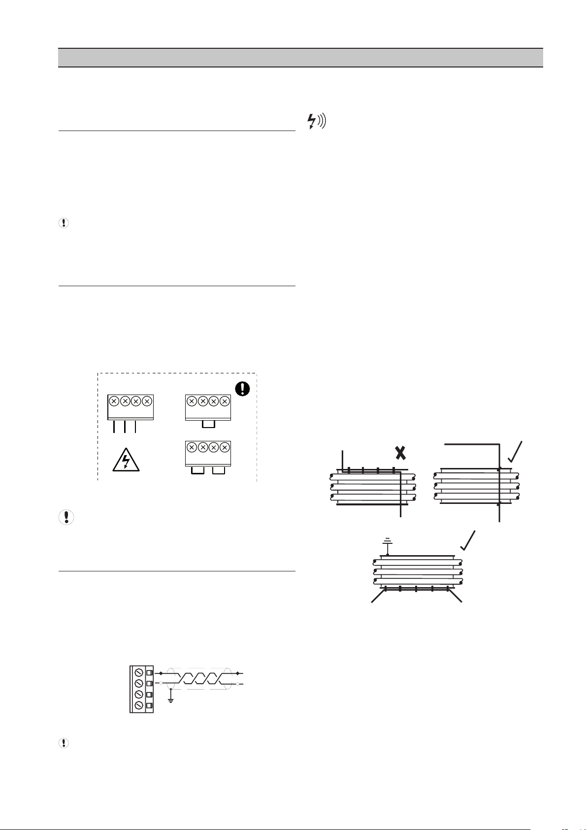
RS485 data communications and other low
voltage signals can be subject to electrical interference.
This potential can result in intermittent malfunction
or anomaly that is difficult to diagnose. To avoid this
possibility always use earth shielded cables, securely
bonded to a known good earth at one end. In addition,
give careful consideration to cable routing during
installation.
a) Never route an RS485 data communications or
low voltage signal cable alongside a high voltage
or 3-phase power supply cable. If it is necessary
to cross the path of a power supply cable(s),
always cross at a right angle.
b) If it is necessary to follow the route of power
supply cables for a short distance (for example:
from a compressor X8I to a wall along a
suspended cable tray) attach the RS485 or
signal cable on the outside of an earthed cable
tray such that the cable tray forms an earthed
electrical interference shield.
c) Where possible, never route an RS485 or signal
cable near to equipment or devices that may be
a source of electrical interference (for example:
3-phase power supply transformer, high voltage
switchgear unit, frequency inverter drive module,
radio communications antenna).
POWER SUPPLY TERMINALS
Ensure that the voltage select input is properly
jumpered for the incoming power. Default voltage
configuration is 230Vac.
RS485 NETWORK
The I/O Box is equipped with an RS485 network
communications capability using the IR485 protocol.
The I/O Box is intended to operate as part of the X8I
Management System. Connection to the system
management unit is two-wire, twisted pair, earth
shielded, RS485 data link. Connect the RS485 data cable
wires to terminal X07.
Note: Polarity is important.
The cable used between the X8I and the I/O Box is
5
Page 6
6
I/O BOX ANALOG CONDITIONING MODULE
1
2
34
4 3 1
X04
XPM-Ai4
XPM-Ai4
1234
30X20X10X
X04
ACM
XPM-Ai4
1
34
4 3 2
Ai1
Ai2
Ai1
Ai2Ai3Ai4
12345678
Ai1
Ai2Ai3Ai4
XPM-Ai4
3338
X10
3437 3235
X09
3136
Ai1
Ai2Ai3Ai4
CAi1CAi2CAi3CAi4
X03
I/O Box
The electrical input characteristics of the four adjustable
analog inputs can be individually altered to suit a sensor
or signal type using Analog Conditioning Modules
(ACM).
ACM devices are hardware modules that plug in to the
analog input circuit and condition the incoming signal.
For a particular sensor type the correct ACM device
must be selected and fitted.
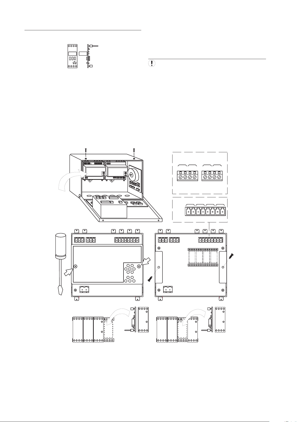
TO CHANGE AN ACM DEVICE:
Remove the power from the unit.
ACM devices for analog inputs 1 to 4 are located within
the unit’s XPM-Ai4 module.
To gain access to the ACM devices remove the cover of
the XPM-Ai4 module. The ACM devices can be removed
and inserted by hand without the use of a tool.
Page 7
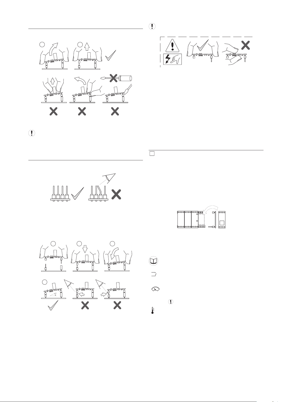
TO REMOVE AN ACM DEVICE:
2
1
1 2 3
4
1
2
34
#
Ai4 Ai3 Ai2 Ai1
ACM
Never use a metallic tool (screwdriver tip for example)
to remove an ACM device.
TO INSTALL AN ACM DEVICE:
Antistatic Precaution
ACM devices contain electronic components; take all
necessary antistatic precautions including:
Before handling an ACM device touch an exposed
1)
earthed surface to discharge any body static.
Always store in an anti-static container or package;
2)
never place on a non anti-static surface.
Handle the device by the edges; never touch the
3)
electronic com[ponenets on the device.
ACM IDENTIFICATION
# ACM devices are classified by a number and can be
readily identified by color:
Any ACM type can be fitted to an analog input socket.
ACM devices can be fitted in the XPM-Ai4 module in any
required combination.
The I/O Box is shipped with four type 3 ACMs installed
and two spare type 6 ACMs.
Example: for analog input 1 (Ai1):
Before inserting an ACM device check the pins of the ACM
and the XPM-Ai4 socket.
ACM devices are designed to mount in the XPM-Ai4
socket at an angle. This is intended to retain the device
securely in the socket in the instance of mechanical
vibration.
When an ACM device is fitted the ‘AT: Input Type’ menu
setting for the analog input must be adjusted to match
the ACM type number.
Menu Items: Analog Inputs A01-A04
Digital Input:
Remote volt-free switching contact
Analog Signal:
DC Voltage or Current
wire polarity is important
Temperature Sensor
7
Page 8

8
3: 0mA
0-20mA
+24VDC
3: 4mA
4-20mA
+24VDC
6: PT1
PT100
3
6
3
2
3
1
3
2
3
1
3
2
3
1
GREEN
RED (Blue)
Page 9

1 2
A:
85%
Ingersoll Rand
IO
Ab.01
Ingersoll Rand
IO
Ab.02
SECTION 5 COMMISSIONING
When commissioning the I/O Box, carry out the following
procedures before attempting to start.
It is recommended that an authorized and trained
service technician perform the commissioning.
PHYSICAL CHECKS
1. Before applying power to the I/O Box, ensure the
power supply connections are correct and secure
and the operating voltage selector is set correctly for
the power supply voltage in use (115Vac or 230Vac
(+-10%), 50/60Hz).
2. Open the front panel of the I/O Box and check the
location of the link wire(s) connected to the “Voltage
Selection” terminals of the power supply PCB. If
necessary, change the link wire locations to those
illustrated for the voltage in use.
See the section on Installation for more
information.
3. Check and ensure all sensor, input, relay and other
connections are correctly installed and secure.
4. Close the front panel of the I/O Box.
5. Switch on the power supply to the I/O Box.
6. The control program identification will be displayed
for a short period followed by the normal operational
user display.
NETWORK ID
The network ID of each I/O Box connected to a system
must be unique. The ID of an I/O Box can be adjusted
from 1 to 12; this also sets the network ID. Assign each
I/O Box a different ID number; starting at ‘1’ increasing
sequentially up to the number of I/O Boxes connected to
the network system.
S01 – Ad
ID and Network Address
sensor and carry out the pressure sensor commissioning
and calibration procedure.
S01 - Po
S01 - Pr
Sensor Offset Calibration
Sensor Range Calibration
Menus and Menu Items
I/O CONFIGURATION
For each I/O function and feature to be utilized, configure
the appropriate I/O configuration items in the associated
menu. Each Input or Output has a dedicated menu.
Menus and Menu Items
Digital Inputs
Analog Inputs
Virtual Relay Automation
For analog inputs; check the type and location of the
ACM devices fitted.
ACM (Analog Conditioning Modules)
VIRTUAL RELAY AUTOMATION
The Ingersoll Rand Automation X8I system is equipped
with virtual relay capability to expand the control of a
compressed air system. Using virtual relay allows the X8I
system to control and monitor ancillary equipment such
as dryers, flow meters, dew point monitors, etc.
When virtual relay capability is activated all inputs and
outputs in the X8I system can be utilized in much the
same way a Programmable Logic Controller (PLC) would
be used to control a system. Each component in the X8I
system has a list of statuses and functions that can be
used as input functions to trigger the virtual relays, which
are logical constructs that are either true or false based on
the input functions but are not necessarily connected to a
physical relay output. Virtual relays can also be connected
to a physical output and thus allow control of equipment
in the system.
An I/O Box must be installed in the automation system
to be able to use virtual relay automation. Please see
the Virtual Relay Automation user’s guide for complete
information.
Menus and Menu Items
REFERENCE SYSTEM PRESSURE DISPLAY
S01- PD Pressure Detect Enable
Check the displayed system pressure if the RP, ‘Reference
Pressure’ , sensor function is utilized. If the pressure is
incorrect, or inaccurate, check the type and range of the
9
Page 10

10
SECTION 6 DISPLAY AND MENU OPERATION
MENU NAVIGATION
Display Item Structure:
All value, parameter or option selection displays are
grouped into menu lists. Items are assigned to a list
according to type and classification. Items that can be
used to select options or modify functions are assigned to
‘menu mode’ lists. Items that a User may require to view
during routine operation, detected pressure for example,
are assigned to the normal operational mode list. Lists
are identified by page number; the normal User display
list is page ‘P00’. All parameters and options are assigned
to menu mode pages ‘P01’ or higher. All page ‘P00’ items
are view only and cannot be adjusted.
Normal Operational Mode (Page P00):
At controller initialisation, all display elements and LED
indicators are switched on for three seconds, the display
will then show the software version code for a further
3 seconds before initialisation is complete and the
normal operating display (Page P0) is shown. In page
P00 ‘normal operational display mode’ the main display
will continuously show the detected delivery pressure
and the Item display will show the first item of the ‘User’
menu. User menu ‘Items’ can be selected using the Up or
Down buttons at any time. Pressing the Enter button will
lock any selected Item display and inhibit return to the
default display. When an Item display is locked the lock
key symbol will slow flash. To unlock an Item display press
Up or Down to view an alternative Item display or press
Reset or Escape. No Item values, options or parameters
can be adjusted in page ‘P00’. If a fault condition occurs
the fault code becomes the first list item and the display
will automatically jump to display the fault code. More
than one active fault code item can exist at any one time.
Access Code:
Access to page list displays higher than page ‘P00’ is
restricted by access code. To access menu mode pages
press MENU, an access code entry display is shown and
the first code character will flash. Use PLUS or MINUS to
adjust the value of the first code character then press
ENTER. The next code character will flash; use UP or
DOWN to adjust then press ENTER. Repeat for all four
code characters.
Menu Mode Navigation:
In menu mode the main value display will flash and show
the Page number. To select a page press UP or DOWN. For
each page the display will show the first Item of the page
list. To view a page list press ENTER, the Page number will
stop flashing and the Item display will flash. Press UP or
DOWN to view the selected page list items. To select an
Item value for modification press ENTER, the Item display
will stop flashing and the value display will flash. The
value or option can now be modified by pressing UP(Plus)
or DOWN(Minus). To enter a modified value or option in
memory press ENTER; alternatively the modification can
be abandoned, and the original setting maintained, by
pressing ESCAPE.
Press ESCAPE at any time in menu mode to step
backwards one stage in the navigation process. Pressing
ESCAPE when the page number is flashing will exit menu
mode and return the display to normal operational mode;
page ‘P00’.
Press and hold RESET for two seconds at any time
to immediately exit menu mode and return to the
normal operational mode display. Any value or option
adjustment that has not been confirmed and entered
into memory will be abandoned and the original setting
maintained.
A flashing Key symbol displayed with any Item
indicates the Item is locked and cannot be modified. This
will occur if the Item is view only (non adjustable) or in
instances where the item cannot be adjusted while the
I/O Box is in ‘Remote Mode’.
If the code number is less than 1000 then the first code
character will be 0(zero). To return to a previous code
character press ESCAPE. When all fourcode characters
have been set to an authorized codenumber press
ENTER. An invalid code will return the display to normal
operational mode; page ‘P00’.
Access Code Timeouts:
When in menu mode, if no key activity is detected for a
period of time the display will automatically reset to the
normal operational display; Page ‘P00’.
Page 11

MENU ITEMS AND SETTINGS
MENU S01CONFIGURATION
1 Ad ID and Network Address
2 PD Pressure Detect Enable
3 Po Pressure Sensor Calibration Offset
4 Pr Pressure Sensor Calibration Range
5 P> Pressure Display Units
6 ID User Menu Item Default
7 RP Pulse Counter Reset Enable
MENU D01 THROUGH D08DIGITAL INPUT FUNCTION
1 ST Normal State (NO or NC)
2 Fn Function (‘-’, A, T, S or P)
3 DT Delay Time
4 RF Reset Function
MENU A01 THROUGH A04ANALOG INPUT CONFIGURATION
1 AT Input Type
2 Ut Display units
3 Vo Value Offset
4 Vr Value Range
5 DF Display Function
6 FH Fault High Level Setpoint
7 FL Fault Low Level Setpoint
8 Fn
9 FI Fault Inhibit Enable
10 Dt Delay Time
11 RT Reset Function
Fault Function
MENU RP1 AND RP2PULSE RELAY
1 F1 Input Function #1
2 F2 Input Function #2
3 Fu Input Logic Function
4 On On Time
5 FS Function State (NO or NC)
6 CF Comms failure function
MENU RF1COMPRESSOR RUNNING RELAY
1 01 Compressor #1 Select
2 02 Compressor #2 Select
... ...
12 12 Compressor #12 Select
13 FN Logic Function
MENU LF1COMPRESSOR LOADED RELAY
1 01 Compressor #1 Select
2 02 Compressor #2 Select
... ...
12 12 Compressor #12 Select
13 FN Logic Function
MENU AF1COMPRESSOR NOT AVAILABLE RELAY
1 01 Compressor #1 Select
2 02 Compressor #2 Select
... ...
12 12 Compressor #12 Select
13 FN Logic Function
MENU R01 THROUGH R06PHYSICAL RELAY
CONFIGURATION
1 F1 Input Function #1
2 F2 Input Function #2
3 Fu Input Logic Function
4 On On Time
5 Of Off Time
6 ST Normal State (NO or NC)
7 CF Comms failure function
MENU R07 THROUGH R13VIRTUAL RELAY CONFIGURATION
Virtual relay will be implemented in a future release
MENU RT1 AND RT3TIME RELAY CONFIGURATION
1 F1 Input Function #1
2 F2 Input Function #2
3 Fu Input Logic Function
4 On On Delay Time
5 Of Off Dellay Time
6 SS
Start State (NO or NC)
7 CF Comms failure function
MENU F10SPM BEARING MONITORING
1 R1 Shaft Speed #1
2 D1 Shaft Diameter #1
3 A1 dBi #1 (View Only)
4 R2 Shaft Speed #2
5 D2 Shaft Diameter #2
6 A2 dBi #2 (View Only)
7 R3 Shaft Speed #3
8 D3
Shaft Diameter #3
9 A3 dBi #3 (View Only)
10 R4 Shaft Speed #4
11 D4 Shaft Diameter #4
12 A4 dBi #4
Analog Inputs: SPMTM Bearing Monitoring Function
MENU 7DIAGNOSTICS
See ‘Diagnostics’
Access Code = 0021
11
Page 12

12
MENU S01 CONFIGURATION
Ad: Box Number and Network Address
I/O Box number and network address. For each I/O Box
in a system assign an I/O Box number starting from ‘1’
increasing sequentially to the number of I/O Boxes in
the system.
For example:
1=I/O Box 01
105=network address; decimal value
Network address values do not always sequentially
follow the I/O Box number sequence; this is normal and
can be ignored.
The I/O Box number must be unique; if two I/O Boxes
are assigned the same number (same network address)
the system will be disrupted.
PD: Pressure Detect Enable
Enables the dedicated reference pressure sensor input.
0 = Disable, no pressure sensor connected
1 = Enable
Po: Reference Pressure Offset Calibration
The value can be adjusted between –22 PSI and +22
PSI (-1.5 bar to +1.5 bar).
Default = 0 PSI (0.0 bar).
The ‘offset’ value can be used for atmospheric
(0psig)calibration; expose the reference pressure sensor
to atmosphere and adjust until the display pressure
shows 0 PSI. The main display value will show the actual
detected pressure when this menu item is selected.
Pr: Reference Pressure Range Calibration
The value can be adjusted for any 4-20mA sensor range
between 14.5 PSI (1 bar) and 9135 PSI (630 bar). Default
= 232 PSI (16 bar).
If the sensor does not have a 0 (zero) PSI offset then
the range value must be the same as the ‘maximum’
pressure value of the sensor.
For example: if the sensor is a –14.5 PSI (-1.0bar) to
217.5 PSI (15 bar) type then:
Offset = -14.5 PSI Range = 217.5 PSI
The ‘range’ value can be used for calibration: expose
the senor to a known accurate pressure and adjust the
‘range’ value until the display pressure matches the
applied pressure. The main display value will show
the actual detected pressure when this menu item is
selected.
P>: Pressure Display Units
0 = bar
1 = psi
2 = kPa
Only applicable to the Reference Pressure display
value.
ID: User Menu Item Default
RP, D1-D8, A1-A4 or R1-R6
Default User menu display item.
After a short period of no keypad activity the User
menu display item will automatically change to show
the item defined by this setting.
RP: Pulse Counter Reset Enable
For any digital input set for ‘pulse count’ mode, this
setting determines if the pulse count can be reset
manually from the User menu.
0 = Remote serial communications reset only
1 = Allow manual reset from User menu
Digital Inputs: Pulse Count Mode
MENU D01 THROUGH D08 DIGITAL
INPUTS
The I/O Box is equipped with 8 digital inputs. A digital
input can be used to monitor the state of a remote voltfree contact that is rated for 24VDC @ 10mA minimum.
The state of a remote contact can be:
a)
Open Circuit (off or ‘0’ state)
Closed Circuit (on or ‘1’ state)
b)
ST Normal State NO/NC
This setting defines if the normal, or OK, state is ‘NO’
normally open circuit (0) or ‘NC’ normally closed circuit
(1).
If the remote contact is detected to change state to the
not normal, or not OK, state the I/O Box will respond in
accordance with the set ‘Fn’ response function.
Fn Function
If the remote contact state is not normal, or not OK, the
I/O Box will indicate:
‘-’ NOK (not OK) – no other action
A
Alarm Condition
T
Trip Condition
S
Signal Connection
The state of the digital input, and any associated
Alarm or Trip condition, is available on remote
communications.
The system management unit will also indicate the
Alarm or Trip condition (dependant on model and
configuration).
The ‘Signal’ state will not activate any alarm condition
but can be detected remotely and used for local or
remote automation.
Virtual Relay Automation
DT Delay Time
If the digital input state changes to the not normal,
or not OK, state the I/O Box will delay any ‘A’, ‘T’ or
‘S’ function response until the state has remained
constantly in the not OK condition for the set delay
time.
Page 13

RF Reset Function
> 0.5 sec > 0.5 sec > 0.5 sec
1
2
0: An ‘A’ Alarm or ‘T’ Trip condition will automatically
reset when the digital input returns to the normal, or
OK, state.
1: An ‘A’ Alarm or ‘T’ Trip condition must be reset
manually by pressing the I/O Box RESET button. The
condition will remain on the display, regardless of input
state, until a manual reset occurs.
Digital Inputs 1 to 8, menus D01 to D08 are identical.
Pulse Count Mode:
Fn
(Function) = P
The function (Fn) of digital Inputs 2 to 7 (D02 to D07)
can be set to monitor a remote volt-free switching
contact and count the number of times the contact
changes state from open circuit to closed circuit and
back to open circuit again; a pulse.
Installation:
ACM - Analog Conditioning Modules
Ut Display Units
The display units item selects the ‘text’ that will be
shown in the user menu item display together with the
analog input value.
Ut = mBr, BAR, PSI, kPa, mPa, dP, oC, oF, m3m,
m3h, cfm, m3, ft3, L/s, L/m, L/h, rpm, SPM, dBn, kW,
kWh, mV, V, kV, mA, A, %
There are 27 ‘unit texts’, any of which can be selected.
Alternatively select “- - -“ (dashes) for no units text
display; the analog input value will be displayed with no
units.
For example:
If the displayed value for analog input #1is tempeature
in degrees celsius; select “oC” as the units text.
The number of detected pulses is displayed in the User
menu and will represent an accumulative metered
value dependant on the device providing the pulses.
The pulse count is stored in non-volatile memory
and will continue to accumulate until reset to zero.
A pulse count can be reset to zero using remote
communications.
If the ‘manual pulse count reset’ option is enabled
(menu S01) each individual digital input pulse count
can be manually reset from the keypad:
Press and hold ENTER then press CANCEL.
The pulse count will be cleared and start immediately
again from zero.
MENUS A01 THROUGH A04 ANALOG
INPUTS
The I/O Box is equipped with 4 adjustable analog
inputs. An analog input can be used to monitor the
signal of a remote compatible device and display an
associating value.
AT Input Type
The input type is dependent on the ACM
(analog conditioning module - hardware) fitted in the
I/O Box for the analog input.
ACM’s are defined by number (1 to 8).
3:0mA
3:4mA
6:PT1
The ‘Input Type’ must be set to match the ACM
device fitted. It is not possible to adjust input signal
types from this setting alone.
0-20mA
4-20mA
PT100 type temperature sensor
The display units ‘text’ has no influence on the
analog input or used in any calculation or remote
communications.
Vo Value Offset
This is the ‘value’ that must be displayed when the
signal is at minimum.
Example #1:
ACM type 3
AT: 3:4mA
Sensor: 4-20mA, 0-232 PSI
The display must show 0 (zero) when the signal is
4.0mA; set ‘Vo’ to 0 (zero).
Example #2:
ACM type 2
AT: 2
Sensor: 1-5 VDC, 0-232 PSI
The display must show 0 (zero) when the signal is 1.0
VDC.
In this instance the analog input (AMC type) is 0-10VDC.
A 0(zero)VDC signal will represent a minus pressure and
a signal voltage greater than 5.0VDC will represent a
pressure greater than 232 PSI. Calculate what the ‘value’
at 0.0VDC must be to achieve a display value of 0(zero)
at 1.0VDC. This will depend on a required ‘value’ of 232
PSI at a signal of 5.0VDC.
To achieve a display ‘value’ of 0(zero)PSI at 1.0VDC, and
232 PSI at 5.0VDC, the ‘Vo’ offset must be set to:
232 PSI divided by (5 – 1)VDC = 58 PSI per 1.0VDC:
therefore 0VDC must be (0 PSI – 58 PSI) = -58 PSI.
Set Vo to “–58”
It is not possible to directly implement decimal
point values. In this instance set a value that is ‘10x’ the
required display value then set ‘DF’ to display the value
13
Page 14

14
at “divide by 10 and show to one decimal place” - see DF
setting.
Vr Value Range
This is the ‘value’ that must be displayed when the
signal is at maximum.
Example #1:
ACM type 3
AT: 3:4mA
Sensor: 4-20mA, 0-232 PSI
The display must show 232 when the signal is 20.0mA;
set Vr to “232”
It is not possible to directly implement decimal
point values. In this instance set a value that is ‘10x’ the
required display value then set ‘DF’ to display the value
at “divide by 10 and show to one decimal place” - see DF
setting.
Example #2:
ACM type 2
AT: 2
Sensor: 1-5 VDC, 0-232 PSI
The display must show 232 when the signal is 5.0 VDC.
In this instance the analog input (AMC type) is 0-10VDC.
A 5.0VDC signal is half the input range. Calculate what
the ‘value’ at 5.0VDC must be to achieve a display value
of 232 at 5.0VDC. This will depend on a required ‘value’
of 0(zero) at a signal of 1.0VDC.
To achieve a display ‘value’ of 232 PSI at 5.0VDC, and 0
PSI at 1.0VDC, the ‘Vr’ offset must be to:
232 PSI divided by (5 – 1)VDC = 58 PSI per 1.0VDC:
therefore 10.0VDC must be 522 to achieve a value of
232 at 5.0VDC.
Set Vr to “522”
It is not possible to directly implement decimal
point values. In this instance set a value that is ‘10x’ the
required display value then set ‘DF’ to display the value
at “divide by 10 and show to one decimal place” - see DF
setting.
DF Display Function
The display function determines how the resulting
‘value’ (as determined by the ‘Vo’ and ‘Vr’ settings) is
displayed in the User menu.
Standard DF Functions:
01: Show value directly
Value: 155 = Display: 155
02: Divide ‘value’ by 10
Display to one decimal place
Value: 155 = Display: 15.
03: Divide ‘value’ by 100
Display to one decimal places
Value: 155 = Display: 1.6
04: Divide ‘value’ by 1000
Display to one decimal place
Value: 155 = Display: 0.2
05: Divide ‘value’ by 100
Display to two decimal place
Value: 155 = Display: 1.55
06: Divide ‘value’ by 1000
Display to two decimal places
Value: 155 = Display: 0.16
For DF = 01 to 06 the value transmitted in remote
communications is always the direct result of the set ‘Vo’
and ‘Vr’ settings; any display DF function is ignored.
Any set FH (Fault High Level Set Point) or FL (Fault
Low Level Set Point) is referenced to the direct result of
the set ‘Vo’ and ‘Vr’ settings; any display DF function is
ignored.
Special DF Functions:
F07: oC to oF Conversion
‘Value’ is assumed to be degrees Celsius multiplied
by ten (oC x 10). ‘Value’ is divided by 10, converted to
degrees Fahrenheit, and displayed with no decimal
places.
The value transmitted in remote communications is the
original ‘value’.
F08: oC Dewpoint @ atmosphere to oC Dewpoint @
pressure conversion.
‘Value’ is assumed to be Dewpoint in degrees Celsius
multiplied by ten (oC x 10) sampled at atmospheric
pressure.
‘Value’ is referenced to the RP (reference pressure sensor
input) and converted to Dewpoint @ pressure in exact
accordance with the detected RP pressure value. An RP
pressure sensor must be fitted and activated.
Resulting ‘value’ is transmitted in remote
communication as oC x 10 (Dewpoint @ pressure x 10).
Display is resulting ‘value’ divided by 10 to one decimal
place = oC (Dewpoint @ Pressure).
Any set FH (Fault High Level Set Point) or FL (Fault
Low Level Set Point) is referenced to the resulting value
(Dewpoint @ pressure x10).
F09: Differential Pressure (mBar)
The differential pressure is between the analog input
and the RP reference pressure sensor.
‘Value’ is assumed to be pressure in milliBar (1.0bar =
1000milliBar).
‘Value’ is referenced to the RP (reference pressure sensor
input). Resulting value is the difference between ‘value’
and RP expressed in milliBar; always positive.
Resulting ‘value’ is transmitted in remote
communication as positive integer milliBar (differential
between analog input and RP reference pressure).
Display is resulting ‘value’ in milliBar; always positive.
Any set FH (Fault High Level Set Point) or FL (Fault
Low Level Set Point) is referenced to the resulting value
in milliBar.
Page 15

F10: SPMTM Bearing Monitoring
22
24
X06
21
23
A
B
‘Value’ is assumed to be ‘dBsv’ (0 to 100) from a
compatible SPMTM bearing monitoring 4-20mA unit and
sensor.
‘Value’ is processed in accordance with SPMTM bearing
monitoring specification to provide resulting ‘dBn’ value.
dBn = dBsv – dBi
‘dBi’ is calculated in accordance with SPMTM specification
from ‘shaft speed (rpm)’ and shaft diameter (mm) entered
in menu F10.
dBi = 20 * (LOG(rpm) + 0.6*LOG(shaft diameter in mm)
– LOG(2150))
R1 = shaft speed: analog input 1
D1 = shaft diameter: analog input 1
A1 = ‘dBi’ value (view only)
to
R4 = shaft speed: analog input 4
D4 = shaft diameter: analog input 4
A4 = ‘dBi’ value (view only)
The calculated ‘dBi’ value can be seen in the F10
bearing monitoring menu (items A1 - analog input #1, to
A4 - analog input #4).
Any set FH (Fault High Level Set Point) or FL (Fault
Low Level Set Point) is referenced to the resulting value
(dBn).
TM
SPM
guidelines for dBn Alarm settings:
OK: <20dBn
Warning 20 to 34dBn
Alarm 35dBn+
Due to the nature of rotary screw or vane compression
elements a serviceable bearing may exhibit a higher than
expected base dBsv level. In this instance the trend over
time of dBsv should be monitored to establish a true dBi
level for the bearing.
Alternatively consult the air compressor supplier/
manufacturer for SPMTM bearing monitoring base level
details and appropriate Warning/Alarm dBn levels.
FH Fault High Level Set Point
If ‘Value’ exceeds this setting the ‘Fault Function’ (Fn) is
triggered.
The setting must be referenced to the same value, or
resulting value, units as the set ‘Vo’ and ‘Vr’ settings.
For example:
If the analog input is Temperature the ‘Value’ will be oC
x 10. If a fault condition needs to be triggered when
temperature exceeds 85oC the FH level should be set to
850 (850 / 10 = 85 oC).
If not required set to, or above, the ‘Vr’ setting.
FL Fault Low Level Set Point
If ‘Value’ decreases below this setting the ‘Fault Function’
(Fn) is triggered.
The setting must be referenced to the same value, or
resulting value, units as the set ‘Vo’ and ‘Vr’ settings.
For example:
If the analog input is Temperature the ‘Value’ will be oC
x 10. If a fault condition needs to be triggered when
temperature reduces below -10oC (minus 10oC) the
FLlevel should be set to -100 (-100 / 10 = -10 oC).
If not required set to, or below, the ‘Vr’ setting.
Fn Fault Function
If ‘Value’ reduces below the set ‘FL’ level or increases above
the set ‘FH’ level the fault function is triggered:
“-“ no action
A Alarm
T Trip
S Signal
All analog input Alarm or Trip fault conditions, are
available on remote communications.
The system management unit will also indicate the
Alarm or Trip condition (dependent on model and
configuration).
The ‘Signal’ state will not activate any alarm condition but
can be detected remotely and used for local or remote
automation.
FI Fault Inhibit Enable
If the analog input is set with an Alarm (A) or Trip
(T) function the alarm condition can be inhibited by
activating digital input ‘FI’ when the FI setting is ‘1’.
0: ‘A’ or ‘T’ condition always active regardless of ‘FI’
digital input state.
1:
‘A’ or ‘T’ condition inhibited if digital input ‘FI’ is
active (closed circuit).
Digital Input ‘FI’
A) not active; open circuit
B) active; closed circuit
Dt Delay Time
If the set ‘FH’ or ‘FL’ fault levels are exceeded the I/O Box
will delay any ‘A’, ‘T’ or ‘S’ function response until the
condition has remained constantly in the fault condition
for the set delay time.
RF Reset Function
0: An ‘A’ Alarm or ‘T’ Trip condition will automatically
reset when the ‘value’ returns to normal, or OK, level.
1: An ‘A’ Alarm or ‘T’ Trip condition must be reset
manually by pressing the I/O Box RESET button. The
condition will remain on the display, regardless of the
‘value’, until a manual reset occurs.
Analog Inputs 1 to 4, menus A01 to A04 are identical.
15
Page 16

16
DIAGNOSTICS
The I/O Box controller is equipped with comprehensive
diagnostic functions. Each input can be examined
individually and each output can be manually activated
or manipulated individually.
I/O Box Controller Diagnostics:
Menu P06 Box Controller Diagnostics
D1
Digital Input 1
D2 Digital Input 2 ON
D3 Digital Input 3
D4
Digital Input 4
D5 Digital Input 5
D6 Digital Input 6
D7 Digital Input 7
D8 Digital Input 8
R1 Relay Output 1
R2 Relay Output 2 OFF
R3 Relay Output 3
R4 Relay Output 4 ON
R5 Relay Output 5
R6 Relay Output 6
A1 Analog Input 1 bar <> mA
A2 Analog Input 2
A3 Analog Input 3
state <> V
state <> V
Relay Outputs:
Each relay output can be energized and de-energized
manually by selecting the item. Use PLUS and MINUS to
adjust ‘on’ (1) or ‘off (0) and then ENTER.
OFF
Analog Inputs:
The item will alternate between the detected value and
the electrical measurement on the input terminals. An
independent measuring device can be used to check
the displayed electrical measurement.
A1: Reference Pressure, 4-20mA
A2: Digital Input #1, voltage
A3: Fault Inhibit Digital Input, voltage
Analog inputs 2 and 3 are equipped with Digital ACM
modules designed to function as standard specification
digital inputs.
D02 Diagnostics – XPM-Ai4 Module
A1 Analog Input 1 as ACM
A2 Analog Input 2 as ACM
A3 Analog Input 3 as ACM
A4 Analog Input 4 as ACM
Configurable Analog Inputs A01 to A04:
The four configurable analog inputs are located in the
XPM-Ai4 module.
The item will alternate between the detected value and
the electrical measurement on the input terminals. An
independent measuring device can be used to check
the displayed electrical measurement.
The detected value and the electrical measurement for
each input will be dependant on the ACM type fitted.
ACM (Analog Conditioning Modules)
Page 17
a
b
c
d
f
g
h
e
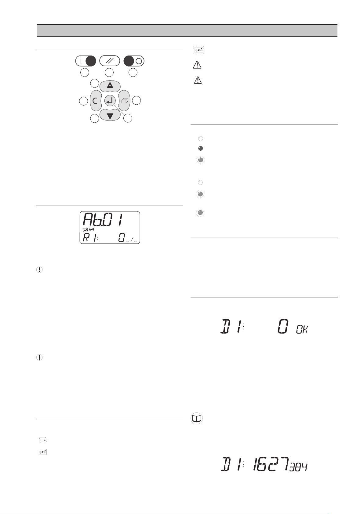
SECTION 7 OPERATION
6.1 USER INTERFACE
a) Start
b) Reset
c) Stop
d) Menu
e) Enter
f) Escape
g) Up (Plus)
h) Down (Minus)
6.2 DISPLAY
Flashing - No Communications
Input Alarm Condition
Input High Level Alarm Condition
Input Alarm or High Level Alarm conditions do not stop
or inhibit I/O Box operation. Examine the User menu item
list to identify the source of an Alarm indication.
6.4 INDICATORS
Run Indicator (Green LED)
OFF I/O Box Shutdown Fault
ON I/O Box Active
Slow Flash I/O Box Network Fault
Fault Indicator (Red LED)
OFF - No fault
Slow Flash:
RP Sensor fault (display “_ _ _ _”)
Flash Flash:
I/O Box Shutdown Fault
6.5 OPERATION
The I/O Box is always active and cannot be stopped.
The upper display will continuously show the assigned
I/O Auxiliary Box number.
If the ‘Reference Pressure’ function is active the upper
display item will continuously show the detected pressure
instead of the I/O Auxiliary Box number.
The lower display will show the default, or selected, user
menu item.
User menu items show the value being detected on
analog input(s) and the state or condition of digital
input(s) and relay outputs.
After a period of no keypad activity the User menu item
will automatically default to show the set ‘default item’
(adjustable in menu S01).
Digital or analog inputs that have not been activated
will not be shown in the User menu item list.
User Menu Items:
A01-A04 Analog Inputs 1 to 4
D01-D08 Digital Inputs 1 to 8
R01-R06
Relay Outputs 1 to 6
The Start and Stop buttons (if fitted) DO NOT affect the
operation of the I/O Box.
The start and stop buttons do have uses in Virtual
Relay Automation, however. Please see the virtual relay
automation manual for details.
6.6 DIGITAL INPUT STATUS INDICATIONS
When activated a ‘Digital Input’ will show the input status
and condition in the User menu item list.
0 = remote contact is open circuit
1 = remote contact is closed circuit
Dependent on the input setup, the display will also show:
OK OK Condition
NOT Not OK Condition
A Alarm State Condition
T
Trip State Condition
S Signal State Condition
6.3 STATUS SYMBOLS
I/O Box Status (always displayed):
Power Failure Auto Restart (always on)
Network communications established
Digital Inputs: Configuration
Pulse Count Mode:
If the digital input is setup in pulse count mode, the User
menu item will show the ‘pulse count’ since last reset.
17
Page 18

18
The number of detected pulses will represent an
1sec
accumulative metered value dependant on the device
providing the pulses.
For example: 1627384 may represent ft3 of air produced
or kWh of power consumed.
If the ‘manual pulse count reset’ option is enabled each
individual digital input pulse count can be reset from the
keypad:
Press and hold ENTER then press CANCEL. The
pulse count will be cleared and start immediately again
from zero.
6.7 ANALOG INPUT DISPLAY
When activated, an ‘Analog Input’ will show a value in
the User menu item list. The value displayed will be
dependant on analog input setup and configuration.
6.10 SHUTDOWN FAULTS
The Fault LED will ‘fast flash’ to indicate a Shutdown
condition. A Shutdown condition will stop normal
operation of the I/O Box. All Shutdown conditions must
be manually reset.
Fault Codes:
Each individual fault has a unique numeric code.
E0010
The wire link between terminals ‘+C’ and ‘C1’ of the unit’s
controller is open circuit. These terminals are permanently
connected together on the IO Box Terminal PCB: this error
will never occur in normal operational circumstances.
Emergency Stop
Analog inputs can be set to indicate an Alarm, High Level
Alarm or Signal condition.
If one of these conditions occurs the analog input
Usermenu item will also display:
A Alarm Condition
T High Level Alarm Condition
S Signal Condition
Analog Inputs: Configuration
Relay Output Display
When activated, a ‘Relay Output’ will show the output
status of the contacts in the User menu item list.
Relay Off: contacts open circuit
Relay On: contacts closed circuit
The function and activation of each relay output is
dependant on setup and configuration.
Virtual Relay Automation
6.8 POWER FAILURE AUTORESTART
The I/O Box will always automatically start when power is
re-applied after a power supply disruption or failure.
6.9 I/O BOX FAULT
If an RP pressure sensor fault is detected (if the RP
pressure sensor option is enabled) the I/O Box will display
“- - - -“ dashes on the upper display and indicate the
condition with an Alarm symbol. The I/O Box will continue
to operate normally without interruption.
E0506
Short circuit condition has been detected on the XPMAi4
module (Analog inputs 1 to 4).
E0821
Short Circuit condition detected on the main controller
unit (digital inputs).
E0836
Internal failure or excessively high external electrical
interference detected.
The main timing circuit (processor clock) has been
disrupted and the processor is running on an ‘internal to
chip’ back-up clock.
The controller’s main power supply must be removed and
re-applied to reset this condition.
E0840
Data communications with the XPM-Ai4 module (analog
inputs 1 to 4) have been disrupted or lost.
E5000
The unit’s controller has detected disruption to the
internal operational memory storage (RAM). The integrity
of the RAM memory contents are suspect; the controller
must be reset to clear and re-map the memory. Renew
the controller if this fault condition persists.
The controller’s main power supply must be removed and
re-applied to reset this condition.
E5001
The unit’s controller has detected disruption to the
internal permanent application memory storage (FLASH).
The integrity of the FLASH memory contents is suspect.
Reload the main application software in the first instance;
renew the controller if the condition persists.
The controller’s main power supply must be removed and
reapplied to reset this condition.
XPM-Ai4 Short Circuit
Short Circuit
PLL Unlock
XPM-Ai4 Communications
Internal Memory Map Error
Internal Memory Failure
Page 19

MANAGEMENT UNIT FAULT CODES
The X8I unit can be set to monitor an IO Box. In this
condition any ‘A’ Alarm or ‘T’ Trip indication will also be
displayed by the X8I.
The X8I will display an IO Box fault code that describes the
IO Box system number and the input (digital or analog)
identification. All inputs on all system IO Box(s) will have a
unique alarm code in the format:
B’nn’ . ’XX’
‘nn’ = IO Box number (01 or 2)
‘XX’ = Input identification Code
The alarm code will also differ dependent on the alarm
type for a particular input (Alarm ‘A’ or Trip ‘T’).
Digital; Input Identification Codes:
Input No. A T
1 01 17
2 02 18
3 03 19
4 04 20
5 05 21
6 06 22
7 07 23
8 08 24
Analog; Input Identification Codes:
Input No. A T
1 49 57
2 50 58
3 51 59
4 52 60
Network Communications Error:
B’nn’. - - -
(IO Box identification followed by dashes)
This message indicates an IR485 network communication
disruption or loss. The management system is no longer
receiving data from the IO Box.
19
Page 20
20
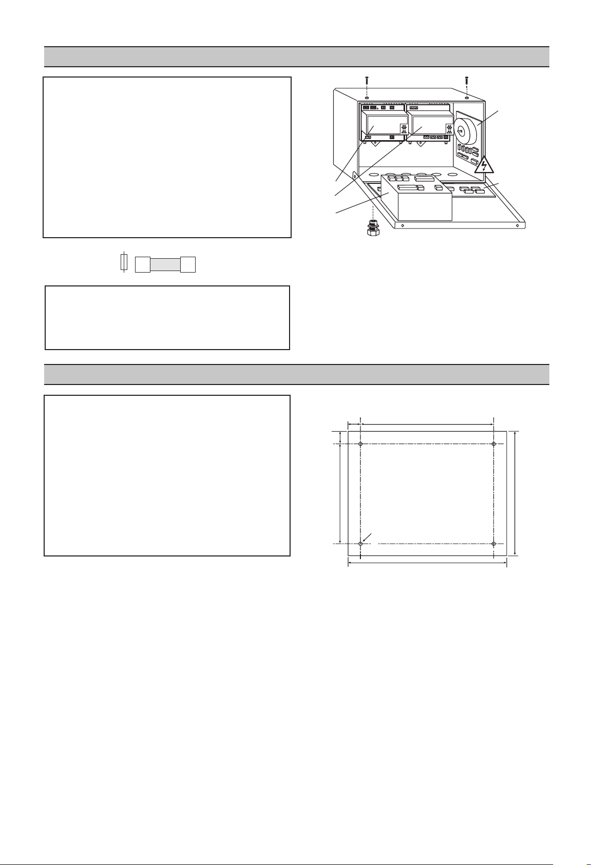
24mm
238mm
24mm
188mm
8mm Ø
236mm
286mm
SECTION 8 PARTS LIST
20mm
5mm
IEC
X
P
M
-
T
A
C2
4
XPM-PSU24
XPM-Ai4
6
4
3
2
1
5
Item Part No. Description
- 42659409 IO Box Kit
- 23242209 IO Box Unit
- 80444086 Manual, User CD
1 42659482 Controller, IO
2 42659284 XPM-PSU24
3 42659326 XPM-Ai4
4 39265913 Unit, XPM-TAC24
5 39265905 PCB, Terminal
6 38036703
Qty Part No. Description
10 39265962 IEC Fuse T1.0A
10 39265970 IEC Fuse T1.6A
10 39265988 IEC Fuse T3.15A
Gland, Set - Pg13.5
SECTION 9 TECHNICAL DATA
Dimensions 291mm x 241mm x 152mm
11.45” x 9.45” x 6.0”
Weight 6.5kg (14Ib)
Mounting wall, 4 x screw fixings
Enclosure IP54, NEMA 12
Supply 230Vac +/- 10%
115Vac +/- 10%
Power 50VA
Temperature 0°C to 46°C (32°F to 115°F)
Humidity 95% RH non-condensing
INSTALLATION AND MOUNTING DIMENSIONS
Page 21
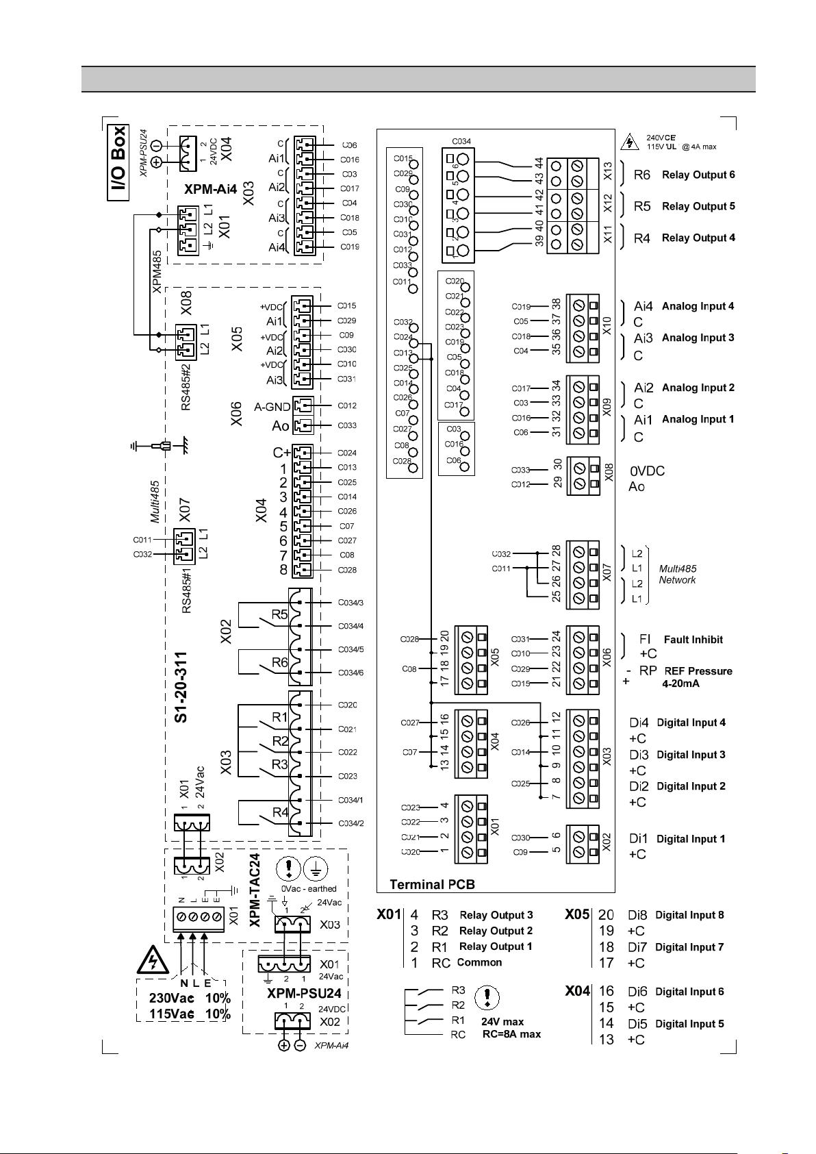
SECTION 10 WIRING DIAGRAM
21
Page 22

22
XPMTAC24
230V
115V
24Vac/1
isolated
24Vac/2
earthed
EE
L
N
N L E
BLUE
BROWN
RED
GREEN
VIOLET
WHITE
ORANGE
BLACK
FH1
FH2FH3
FH4
FH5
1
VOLTAGE SELECT
2 3 4
X04
2 1 2
X03
X02
X01
T3.15A
T1.6A
T1.6A
T1.0A
T1.0A
1 2 3 4
115V +-10%
230V +-10%
1 2 3 4
IEC
5x20mm
Page 23

Customer
Contact
Phone
Installation/Site
Ser No.
Software
Commission Date
Commission Engineer
Customer Ref:
Internal Ref:
S01 Ad Box Number (Network Address)
S01 PD Reference Pressure Detect Enable
isp/ rabnoitarbilaC tesffO PRoP10S
isp/ rabnoitarbilaC egnaR PRrP10S
S01 P> RP Pressure Display Units
S01 ID Default User Menu Item
S01 RP Pulse Counter Reset Enable
1 2 3
4
5
6 7 8 9
10
11
12
bar psi kPa
0 1:on
0 1:on
d01 ST Normal State
d01 Fn Function
d01 DT Delay Time sec
d01 RF Reset Function
“-“ A T
NO NC
0 1:on
S
d02 ST Normal State
d02 Fn Function
d02 DT Delay Time sec
d02 RF Reset Function
“-“ A T
NO NC
0 1:on
S P
d03 ST Normal State
d03 Fn Function
d03 DT Delay Time sec
d03 RF Reset Function
“-“ A T
NO NC
0 1:on
S P
d04 ST Normal State
d04 Fn Function
d04 DT Delay Time sec
d04 RF Reset Function
“-“ A T
NO NC
0 1:on
S P
d05 ST Normal State
d05 Fn Function
d05 DT Delay Time sec
d05 RF Reset Function
“-“ A T
NO NC
0 1:on
S P
d06 ST Normal State
d06 Fn Function
d06 DT Delay Time sec
d06 RF Reset Function
“-“ A T
NO NC
0 1:on
S P
d07 ST Normal State
d07 Fn Function
d07 DT Delay Time sec
d07 RF Reset Function
“-“ A T
NO NC
0 1:on
S P
d08 ST Normal State
d08 Fn Function
d08 DT Delay Time sec
d08 RF Reset Function
“-“ A T
NO NC
0 1:on
S
I/O Commissioning Form
23
Page 24

A01 AT Input Type
A01 Ut Display Units
A01 Vo Value Offset Calibration
A01 Vr Value Range Calibration
A01 DF Display Function
A01 FH Fault High Level Set Point
A01 FL Fault Low Level Set Point
A01 Fn Fault Function
A01 FI Fault Inhibit Function Enable
cesemiT yaleDtD10A
A01 RT Reset Function
“-“
1
0 1:on
0 1:on
“-“ A T S
2 3 4 5 6 F7 F8 F9 F10
1:no 2:10V 3:0mA
7
6 8
1:nc
3:4mA
4:0mA
4:4mA
5:KTY
5:RTD
A02 AT Input Type
A02 Ut Display Units
A02 Vo Value Offset Calibration
A02 Vr Value Range Calibration
A02 DF Display Function
A02 FH Fault High Level Set Point
A02 FL Fault Low Level Set Point
A02 Fn Fault Function
A02 FI Fault Inhibit Function Enable
cesemiT yaleDtD20A
A02 RT Reset Function
“-“
1
0 1:on
0 1:on
“-“ A T S
2 3 4 5 6 F7 F8 F9 F10
1:no 2:10V 3:0mA
7
6 8
1:nc
3:4mA
4:0mA
4:4mA
5:KTY
5:RTD
A03 AT Input Type
A03 Ut Display Units
A03 Vo Value Offset Calibration
A03 Vr Value Range Calibration
A03 DF Display Function
A03 FH Fault High Level Set Point
A03 FL Fault Low Level Set Point
A03 Fn Fault Function
A03 FI Fault Inhibit Function Enable
cesemiT yaleDtD30A
A03 RT Reset Function
“-“
1
0 1:on
0 1:on
“-“ A T S
2 3 4 5 6 F7 F8 F9 F10
1:no 2:10V 3:0mA
7
6 8
1:nc
3:4mA
4:0mA
4:4mA
5:KTY
5:RTD
A04 AT Input Type
A04 Ut Display Units
A04 Vo Value Offset Calibration
A04 Vr Value Range Calibration
A04 DF Display Function
A04 FH Fault High Level Set Point
A04 FL Fault Low Level Set Point
A04 Fn Fault Function
A04 FI Fault Inhibit Function Enable
cesemiT yaleDtD40A
A04 RT Reset Function
“-“
1
0 1:on
0 1:on
“-“ A T S
2 3 4 5 6 F7 F8 F9 F10
1:no 2:10V 3:0mA
7
6 8
1:nc
3:4mA
4:0mA
4:4mA
5:KTY
5:RTD
ACM
ACM
ACM
ACM
mpr1# deepS tfahS1r01F
mm1# retemaiD tfahS1d01F
mpr2# deepS tfahS2r01F
mm2# retemaiD tfahS2d01F
mpr3# deepS tfahS3r01F
mm3# retemaiD tfahS3d01F
mpr4# deepS tfahS4r01F
mm4# retemaiD tfahS4d01F
SPM Bearing Monitoring
24
Page 25

Page 26

LOOK WHAT INGERSOLL RAND CAN DO FOR YOU!
Efficient Field Service
We maintain a highly trained staff of technicians
to service your equipment for preventive
maintenance, or to assist you should emergencies
ever occur.
Complete Repair Service
Our trained technicians will repair or overhaul
your equipment to factory specifications,
using only genuine Ingersoll Rand parts.
Special Engineering Service
We can help you identify and solve your problems
by evaluating your needs and recommending
theproper equipment to give your maximum
efficiency.
Spare Parts
By stocking genuine Ingersoll Rand spare
parts, we can help you avoid costly delays
or substituting inferior parts. Using genuine
Ingersoll Rand parts on you Ingersoll
Rand equipment will help to keep even
older equipment running in good-as-new
Complete Stock of Equipment
We carry a complete line of Ingersoll Rand
equipment and accessories designed to meet
any compressed air application. We are backed
by Ingersoll Rand’s prompt factory shipment to
ensure you on-time delivery.
condition.
A SUBSTITUTE IS NOT A REPLACEMENT!
Ensure you get peak performance and longevity out of your Ingersoll Rand product by insisting on genuine Ingersoll
Rand replacement parts and maintenance kits. Not only are the replacement parts made to precise dimensions and OEMspecified metallurgy, but each part is backed by the Ingersoll Rand warranty. Your local Customer Center, Distributor, or
direct Ingersoll Rand salesperson will work with your to ensure you get the parts you need to do the job right. Equip your
machines with only the best Ingersoll Rand genuine parts.
NOTE: THE USE OF REPAIR PARTS OTHER THAN THOSE INCLUDED WITHIN THE INGERSOLL RAND COMPANY
APPROVED PARTS LIST MAY CREATE UNSAFE CONDITIONS OR MECHANICAL FAILURES OVER WHICH INGERSOLL
RAND COMPANY HAS NO CONTROL. INGERSOLL RAND COMPANY SHALL BEAR NO RESPONSIBILITY FOR
EQUIPMENT ON WHICH NON-APPROVED REPAIR PARTS ARE INSTALLED.
The manufacturer reserves the right to make changes or add improvements without notice and without incurring any
obligation to make such changes to products previously sold.
 Loading...