

Page 1

Ingersoll Rand System Automation
ENGLISH
FRENCH
GERMAN
DUTCH
PRINT LANGUAGE
ITALIAN
SPANISH
IX IntelliFlow
Operator’s Manual
80445570
Revision D
January 2012
DE
Bedienungshandbuch
EN
Operator’s Manual
ES
Manual De Operadores
FR
Manuel De L’utilisateur
IT
Manuale D’uso
NL
Gebruiksaanwijzingen
Save These Instruction
Page 2

SECTION 1 TABLE OF CONTENTS
Section 1 - table of contentS .............................2
DeclaRation of confoRMitY ...............................3
Section 3 - intRoDUction ......................................4
Section 4 - SafetY ....................................................4
SAFETY PRECAUTIONS .............................................4
SHIPMENT INSPECTION / PREINSTALLATION CHECK 4
INSTALLATION .............................................................................4
OPERATION ...................................................................................4
MAINTENANCE AND REPAIR .................................................5
Section 5 - connection anD contRol .............6
OPERATING MODES .................................................................6
Section 6 - inStallation .........................................8
IX INTELLIFLOW TECHNICAL DATA .....................................8
IX INTELLIFLOW INSTALLATION ...........................................9
IX BOX POWER SUPPLY ..........................................................10
IX INTELLIFLOW VALVE CONTROLLER CONNECTION
AND SENSOR ARRANGEMENT ............................................10
IX BOX RS485 NETWORK .......................................................11
Section 7 - DiSPlaY anD MenU oPeRation ....12
Section 8 - coMMiSSioninG .................................14
Section 10 - DiaGnoSticS .....................................21
DIAGNOSTIC MENU 5 .............................................................21
Section 11 - faUlt coDeS ......................................22
Section 12 - iX intellifloW contRolleR PaRt
liSt ..................................................................................23
Section 13 - iX intellifloW contRolleR
tecHnical Data .........................................................23
Section 14 - iX intellifloW contRolleR
WiRinG DiaGRaM .......................................................24
ENCLOSURE MOUNTING .......................................................26
Section 15 - iX intellifloW contRolleR
ReMote inPUtS ..........................................................27
IX BOX INPUT FUNCTIONS ...................................................27
VIRTUAL RELAY AUTOMATION ...........................................27
Section 16 - iX intellifloW contRolleR RS485
MoDbUS ReGiSteRS ...................................................28
Section 17 - iX intellifloW DiGital
PoSitioneR ..................................................................29
IX INTELLIFLOW DIGITAL POSITIONER SETUP
PROCEDURE ...............................................................................29
Section 18 - iX intellifloW actUatoR fail
oPen to fail cloSeD ................................................39
PHYSICAL CHECKS ...................................................................14
PRESSURE DISPLAY .................................................................14
OPERATING MODE ...................................................................14
PRESSURE SET POINTS ...........................................................14
IX BOX OPTIONAL FEATURES AND FUNCTIONS .........14
IX INTELLIFLOW STARTUP ...................................................14
SETTING THE TUNING PARAMETERS ................................15
Section 9 - SYSteM confiGURation .................16
DISPLAY AND MENU OPERATION......................................16
ACCESSING THE IX CONFIGURATION SCREENS ...........16
CONFIGURATION MENU OVERVIEW ................................17
USER CONFIGURATION MENU 1 ........................................18
PRESSURE TARGET MENU 2 .................................................20
SENSOR CALIBRATION MENU 3 ..........................................20
RELAY CONFIGURATION MENU 4 ......................................20
Section 19 - iX intellifloW aSSeMblY
oVeRVieW DRaWinG .................................................40
Section 20 - iX intellifloW aSSeMblY
DiMenSionS “incHeS” ..............................................41
Section 21 - iX intellifloW aSSeMblY
DiMenSionS “MilliMeteR” ......................................43
Section 22 - iX intellifloW aSSeMblY SPaRe
PaRtS liSt .....................................................................45
REFER TO SECTION INDICATED
NOTE
IMPORTANT OR CAUTION, SAFETY
2 Ingersoll Rand System Automation IX Intelliow
ingersollrandproducts.com
Page 3
DECLARATION OF CONFORMITY
(ES) DECLARACIÓN DE CONFORMIDAD (FR) CERTIFICAT DE CONFORMITÉ (IT) DICHIARAZIONE DI CONFORMITÀ
(DE) KONFORMITÄTSERKLÄRUNG (NL) SCHRIFTELIJKE VERKLARING VAN CONFORMITEIT (DA) FABRIKATIONSERKLÆRING
(SV) FÖRSÄKRAN OM ÖVERENSSTÄMMELSE (NO) KONFORMITETSERKLÆRING (FI) VAKUUTUS NORMIEN TÄYTTÄMISESTÄ
(PT) DECLARAÇÃO DE CONFORMIDADE (EL) ΗΛΣΗ ΑΝΑΓΝΡΙΣΗΣ (SL) IZJAVA O SKLADNOSTI (SK) PREHLÁSENIE O
ZHODE (CS) PROHLÁŠENÍ O SHODĚ (ET) VASTAVUSDEKLARATSIOON (HU) MEGFELELŐSÉGI NYILATKOZAT (LT) ATITIKTIES
PAREIŠKIMAS (LV) ATBILSTĪBAS DEKLARĀCIJA (PL) DEKLARACJA ZGODNOŚCI
Ingersoll Rand 1302 GOSHEN PARKWAY, WEST CHESTER, PA 19380
DECLARE THAT UNDER OUR SOLE RESPONSIBILTY FOR MANUFACTURE AND SUPPLY, THE PRODUCT(S),
IX-050, IX-080, IX-100, IX-150, IX-200, IX-050HT, IX-080HT, IX-100HT, IX-150HT, IX-200HT
(ES) Declaramos que, bajo nuestra responsabilidad exclusiva, el producto: (FR) Déclarons sous notre seule responsabilité que le produit:
(IT) Dichiariamo sotto la nostra unica responsabilità che il prodotto: (DE) Erklären hiermit, gemäß unserer alleinigen Verantwortung, daß
die Geräte: (NL) Verklare n, onder onze uitsluitende aansprakelijkheid, dat het produkt: (DA) Erklærer som eneansvarlig, at nedenstående
produkt: (SV) Intygar härmed, i enlighet med vårt fullständiga ansvar, att produkten: (NO) Erklærer som eneansvarlig at produktet:
(FI) Vakuutamme ja kannamme yksin täyden vastuun siitä, että tuote: (PT) Declaramos sob a nossa exclusiva responsabilidade que o
produto: (EL) ηλώνουε ότι ε δική α ευθύνη το προϊόν: (SL) Pod polno odgovornostjo izjavljamo, da se izdelek: (SK) Prehlasujeme na
svoju zodpovednost’, že produkt: (CS) Prohlašujeme na svou zodpovědnost, že výrobek: (ET) Deklareerime oma ainuvastutusel, et toode:
(HU) Kizárólagos felelősségünk tudatában kijelentjük, hogy a termék: (LT) Prisiimdami atsakomybę pareiškiame, kad gaminys:
(LV) Uzņemoties pilnīgu atbildību, apliecinām, ka ražojums: (PL) Oświadcza, że ponosi pełną odpowiedzialność za to, że produkt:
To which this declaration relates, is in compliance with provisions of Directive(s): 97/23/EC., 93/68/EEC, 2004/108/EC, 2006/95/EC
(ES) a los que se reere la presente declaración, cumplen con todo lo establecido en las directivas: (FR) objet de ce certicat, est conforme
aux prescriptions des Directives: (IT) a cui si riferisce la presente dichiarazione è conforme alle normative delle direttive: (DE) auf die sich
diese Erklärung bezieht, den Richtlinien: (NL) waarop deze verklaring betrekking heeft overeenkomt met de bepalingen van directieven:
(DA) som denne erklæring vedrører, overholder bestemmelserne i følgende direktiver: (SV) som detta intyg avser, uppfyller kraven i
Direktiven: (NO) som denne erklæringen gjelder for, oppfyller bestemmelsene i EU-d irektivene: (FI) johon tämä vakuutus viittaa, täyttää
direktiiveissä: (PT) ao qual se refere a presente declaração, está de acordo com as prescrições das Directivas: (EL) τα οποία αφορά αυτή
η δήλωση‚ είναι σύφωνα ε τι προβλέψει των Eντολών: (SL) Na katerega se ta izjava o skladnosti nanaša, sklada z določili smernic:
(SK) Ku ktorému sa toto prehlásenie vzt’ahuje, zodpovedá ustanoveniam smerníc: (CS) Ke kterým se toto prohlášení vztahuje, odpovídají
ustanovením směrnic: (ET) Mida käesolev deklaratsioon puudutab, on vastavuses järgmis(t)e direktiivi(de) sätetega: (HU) Amelyekre ezen
nyilatkozat vonatkozik, megfelelnek a következő irányelv(ek) előírásainak: (LT) Kuriems taikomas šis pareiškimas, atitinka šios direktyvos
nuostatas: (LV) Uz kuru šī deklarācija attiecas, atbilst direktīvas(u) nosacījumiem: (PL) Do których ta deklaracja się odnosi, są zgodne z
postanowieniami Dyrektywy (Dyrektyw):
By using the following Principle Standards: ASME B31.1, EN61000-6-2:2001, EN61000-6-4:2001, EN60204-1:1997
(ES) conforme a los siguientes estándares: (FR) en observant les normes de principe suivantes: (IT) secondo i seguenti standard:
(DE) unter Anlehnung an die folgenden Grundnormen entsprechen: (NL) overeenkomstig de volgende hoofdstandaards: (DA) ved at
være i overensstemmelse med følgende hovedstandard(er): (SV) Genom att använda följande principstandard: (NO) ved å bruke følgende
prinsipielle standarder: (FI) esitetyt vaatimukset seuraavia perusnormeja käytettäessä: (PT) observando as seguintes Normas Principais:
(EL) Χρησιοποιώντα ια παρακάτω κύρια πρότυπα: (SL) Uporabljeni osnovni standardi: (SK) Použitím nasledujúcich zákonných noriem: (CS) Použitím následujících zákonných norem: (ET) Järgmiste põhistandardite kasutamise korral: (HU) A következő elvi szabványok
alkalmazásával: (LT) Remiantis šiais pagrindiniais standartais: (LV) Izmantojot sekojošos galvenos standartus: (PL) Przy zastosowaniu
następujących podstawowych norm:
Date: May, 2010
(ES) Fecha: Mayo, 2010: (FR) Date: Mai, 2010: (IT) Data: Maggio, 2010: (DE) Datum: Mai, 2010: (NL) Datum: Mei, 2010:
(DA) Dato: Må, 2010: (SV) Datum: Maj, 2010: (NO) Dato: Mai, 2010: (FI) Päiväys: Toukokuu, 2010: (PT) Data: Maio, 2010:
(EL) Ηεροηνία: Μάιο, 2010: (SL) Datum: Maj, 2010: (SK) Dátum: Máj, 2010: (CS) Datum: Květen, 2010: (ET) Kuupäev: Mai, 2010: (HU) Dá-
tum: Május, 2010: (LT) Data: Gegužė , 2010: (LV) Datums: Maijs, 2010: (PL) Data: Maj, 2010
Approved By:
(ES) Aprobado por: (IT) Approvato da: (FR) Approuvé par: (DE) Genehmigt von: (NL) Goedgekeurd door: (DA) Godkendt af:
(SV) Godkänt av: (NO) Godkjent av: (FI) Hyväksytty: (PT) Aprovado por: (EL) Eγκρίθηκεαπό: (SL) Odobril: (SK) Schválil: (CS) Schválil: (ET)
Kinnitatud: (HU) Jóváhagyta: (LT) Patvirtinta: (LV) Apstiprināja: (PL) Zatwierdzone przez
H. MARK
H. MARK, ENGINEERING MANAGER
J. FARLEY, QUALITY ASSURANCE MANGER
J. FARLEY
ingersollrandproducts.com 3
Page 4
SECTION 3 INTRODUCTION
!
!
IX IntelliFlow is an intermediate system controller that
controls the system air pressure. The IX IntelliFlow can
control the Demand Side, Supply Side, or a combination
of both using user selectable set-points.
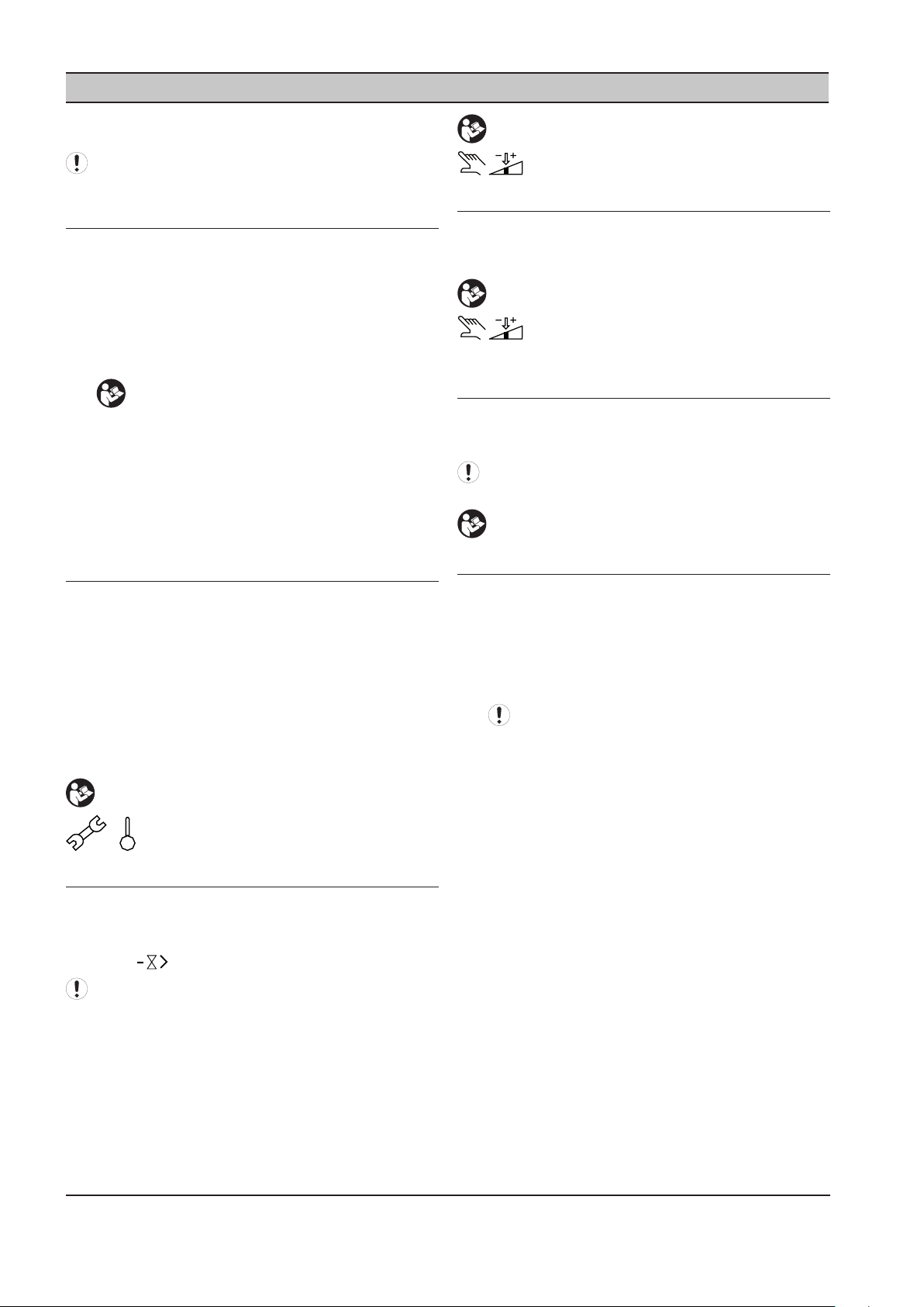
SECTION 4 SAFETY
SAFETY PRECAUTIONS
WARNING : Risk of Danger
WARNING : Risk of Electric Shock
WARNING : Risk of High Pressure
WARNING : Consult Manual
Before installing or operating the IX IntelliFlow, take
•
time to carefully read all the instructions contained
in this manual, all compressor manuals, and all
manuals of any other peripheral devices that may be
installed or connected to the unit.
Electricity and compressed air have the potential to
•
cause severe personal injury or property damage.
The operator should use common sense and good
•
working practices while operating and maintaining
this system. All applicable codes should be strictly
adhered to.
Maintenance must be performed by adequately
•
qualied personnel that are equipped with the
proper tools.
SHIPMENT INSPECTION / PRE
INSTALLATION CHECK
The crating should be inspected for shipping
•
damage after the unit has arrived.
The lter regulator assembly is shipped loose
•
with the IX controller. The assembly is packaged
in a box that is stored underneath the controller
mounting bracket. Please notify the shipper if this
box is missing or if tampering has occurred with the
shipping crate.
After the unit has been removed from the crate,
•
re-tighten all bolt connections as required prior to
installation to the appropriate torque specication.
The IX IntelliFlow is equipped with a locally mounted
PID controller (IX Box) which modulates the valve to
maintain a constant pressure [+/- .75 psi (0.05 bar)]
given the application of appropriately sized storage.
INSTALLATION
Installation work must only be carried out by a
•
competent person under qualied supervision.
A fused disconnect / isolation switch must be
•
tted between the main power supply and the IX
IntelliFlow. This should be located in close proximity
to the controller. The power consumption of the
controller is listed in the IX IntelliFlow Controller
Technical Data section of this manual. The power
installation shall be performed in accordance to
locally and nationally recognized electrical codes.
The IX IntelliFlow should be mounted in such a
•
location as to allow operational and maintenance
access without obstruction or hazard and to allow
clear visibility of indicators at all times.
If raised platforms are required to provide access
•
to the IX IntelliFlow, they must not interfere with
normal operation or obstruct access.
OPERATION
The IX IntelliFlow must only be operated by
•
competent personnel under qualied supervision.
Never remove or tamper with safety devices, guards
•
or insulation materials tted to the IX IntelliFlow.
The IX IntelliFlow must only be operated at the
•
supply voltage and frequency for which it is
designed.
When main power is switched on, lethal voltages are
•
present in the electrical circuits and extreme caution
must be exercised whenever it is necessary to carry
out any work on the unit.
Do not open access panels or touch electrical
•
components while voltage is applied unless it is
necessary for measurements, tests or adjustments.
Such work should be carried out only by a qualied
electrician equipped with the correct tools and
wearing appropriate protection against electrical
hazards.
All air compressors and/or other equipment
•
connected to the unit should have a warning sign
attached stating “THIS UNIT MAY START WITHOUT
WARNING” next to the display panel.
4 ingersollrandproducts.com
Page 5

If an air compressor and/or other equipment
•
connected to the unit is to be started remotely,
attach two warning signs to the equipment stating
“THIS UNIT CAN BE STARTED REMOTELY”. Attach
one sign in a prominent location on the outside
of the equipment, and the other sign inside the
equipment control compartment.
The IX IntelliFlow is designed for use on air piping
•
systems with a maximum pressure of 200 PSIG
(13.78 bar) at a maximum temperature of 150˚F
(65˚C).
Operation of equipment outside of stated
•
conditions may result in equipment damage or
injury. A eld supplied and installed pressure
limiting device (e.g. pressure relief valve) must be
installed in piping system.
MAINTENANCE AND REPAIR
Maintenance, repairs or modications must only
•
be carried out by competent personnel under
qualied supervision.
If replacement parts are required, use only genuine
•
parts from the original equipment manufacturer, or
an alternative approved source.
Make sure that all instructions concerning
•
operation and maintenance are strictly followed
and that the complete unit, with all accessories
and safety devices, is kept in good working order.
The accuracy of sensor devices must be checked
•
on a regular basis. They must be calibrated when
acceptable tolerances are exceeded. Always ensure
any pressure within the compressed air system is
safely vented to atmosphere before attempting to
remove or install a sensor device.
The IX IntelliFlow must only be cleaned with a
•
damp cloth, using mild detergents if necessary.
Avoid the use of any substances containing
corrosive acids or alkalis.
Do not paint the control faceplate or obscure any
•
indicators, controls, instructions or warnings.
Carry out the following operations before opening
•
or removing any access panels or carrying out any
work on the IX IntelliFlow:
i. Isolate the IX IntelliFlow from the main
electrical power supply. Lock the isolator in the
“OFF” position and remove the fuses.
ii. Attach labels to the isolator switch and to the
unit stating “WORK IN PROGRESS - DO NOT
APPLY VOLTAGE”. Do not switch on electrical
power or attempt to start the IX IntelliFlow if
such a warning label is attached.
ingersollrandproducts.com 5
Page 6
SECTION 5 CONNECTION AND CONTROL
70
psi
80
90
100
110
120
130
140
150
160
P4
P3
Ao
105
P4 Target = 95
1
2
100%
0%
115
95
P3 P4
3
70
psi
80
90
100
110
120
130
140
150
160
P4
P3
Ao
100
110
1
P3 P4
P3 Target = 80
2
3
0%
100%
100
110
80
The IX IntelliFlow Air System Pressure/Flow Controller
can provide precise pressure control for Demand Side
(compressed air usage), Supply Side (compressed air
generation or Back Pressure control) applications as well
as a combination of Demand/Supply control applications.
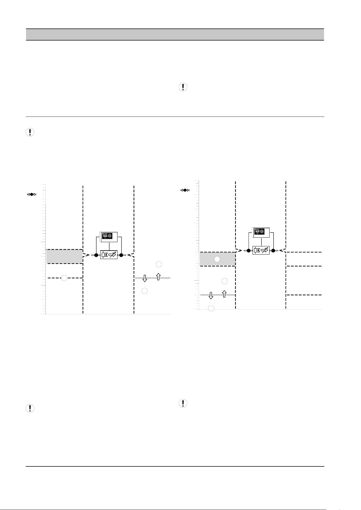
OPERATING MODES
1) Demand Side or Forward Mode Pressure Control
This is the Default, As Shipped, from the Factory
Conguration
Used to accurately control Demand Side pressure (P4)
system using air from the Supply Side (P3).This mode of
operation is intended to ensure that a constant Demand
or Outlet side pressure is maintained.
The IX IntelliFlow separates the supply side from the
demand side. By doing so, the supply side is not aected
by specic demand events. The IntelliFlow is able to
handle transient demand events without the need for
extra compression equipment to come on-line.
All IX IntelliFlow applications must include the
installation of the proper receiver volume.
2) Supply Side / Back Pressure or Backward Mode
Pressure Control
Used to protect the Inlet or Supply Side (P3) system from
pressure decay due to excess air usage from the Demand
Side (P4). This mode of operation is intended to ensure
that a minimum specied Supply or Inlet side pressure is
maintained.
If P3 remains above 95psi (6.55 bar):
P4 is maintained at P4 target:
If demand increases and P4 falls below 95psi (6.55 Bar):
Valve opens towards 100% (1)
If demand decreases and P4 increases above 95psi (6.55
Bar):
Valve closes towards 0% (2)
If P3 falls below 95psi (6.55 Bar):
Valve will open 100% and P4 pressure will equal
Valve remains fully open and P4 pressure will
equal P3 pressure (1).
If P3 falls to 80psi (5.51 bar):
P3 is protected from falling below 80psi:
If P3 falls below 80psi (5.51 bar):
Valve closes towards 0% (2)
If P3 increases above 80psi (5.51 bar):
Valve opens towards 100% (3) and P4 pressure
will equal P3 pressure.
P3 pressure (3).
The IX IntelliFlow is set to Fail Open by Default. To
If P3 remains above 80psi (5.51 bar):
The IX IntelliFlow is set to Fail Open by Default
6 ingersollrandproducts.com
change to Fail Closed, Please refer to Section 16
Page 7
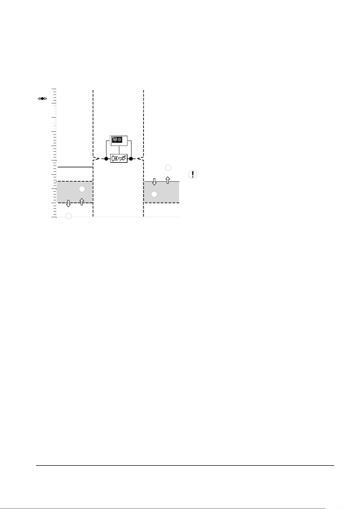
3) Combination Demand / Supply Side or Combination
70
psi
80
90
100
110
120
130
140
150
160
P4
P3
Ao
105
P3 Target = 80
P4 Target = 95
1
2
100%
0%
3
4
0%
100%
80
P3 P4
Mode Pressure Control
Used to accurately control pressure of the Demand Side
pressure (P4) system using air from the Supply Side (P3)
system while protecting the Supply Side (P3) system from
pressure decay due to excess air usage from the Demand
Side (P4) system
If P3 remains above 95psi (6.55 bar):
P4 is maintained at P4 target:
If demand increases and P4 falls below 95psi (6.55 bar)
Valve opens towards 100% (1)
If demand decreases and P4 increases above 95psi (6.55
bar):
Valve closes towards 0% (2)
If P3 falls below 95psi (6.55 bar) but remains above 80psi
(5.51 bar):
Valve will open 100% and P4 pressure will equal
P3 pressure.
If P3 falls to 80psi (5.51 bar):
P3 is protected from falling below 80psi (5.51
bar):
If P3 falls below 80psi (5.51 bar):
Valve closes towards 0% (3)
If P3 increases above 80psi (5.51 bar):
Valve opens towards 100% (4)
The IX IntelliFlow is set to Fail Open by Default. To
change to Fail Closed, Please refer to Section 16
ingersollrandproducts.com 7
Page 8

SECTION 6 INSTALLATION
IX INTELLIFLOW TECHNICAL DATA
VALVE ASSEMBLY
Available in 2” to 8” (50 to 200mm) congurations.
•
Piping is A53, Grade B, Type E, Schedule 40 welded
•
steel.
Connections are ANSI / DIN Raised Face anges and
•
are design rated for 200 lb (13.87 Bar) ANSI / DIN.
The valve body material is cast iron ASTM A126 Class
•
B design.
The valve stem material is 416 stainless Steel ASTM
•
A582 Type 416 design.
The valve seat material is bonded Buna-N Food
•
Grade design.
The valve disc material is Nylon 11 coated ductile
•
iron ASTM A536 Gr.65-45-12 design.
Taps: 1 upstream of the valve for control air and
•
pressure transducer (P3), 1 downstream of the valve
for the pressure gage and pressure transducer (P4),
1 upstream & 1 downstream of the valve for drain
ports, 1 upstream & 1 downstream of the valve for
eld instruments.
Assemblies are assumed to be installed in a building
•
and thereby protected from the elements. Electrical
enclosures are designed to meet the requirements
for a NEMA 12 / IP54 rating. Assembly is CRN listed
Ambient Operating Conditions: between 35°F and
•
115°F (2°C and 46°C), humidity from 0-95% noncondensing and inlet pressures not to exceed
200 PSIG (13.78 bar).
Downstream set point should be at least 5 PSIG (0.3
•
bar) below minimum upstream pressure.
Pressure turndown typically ≤ 30% maximum.
•
The valve has no eld adjustments necessary to
•
maintain optimum eld performance.
Inlet air temperature to valve not to exceed 150°F
•
(66°C).
Minimum control supply pressure (upstream of
•
valve) of 80 PSIG (5.5 bar).
Nominal pressure drop should not exceed 1 PSIG
•
(0.06 bar) across entire assembly with valve fully
open.
The valve actuator is a direct mounted pneumatic,
•
rack & pinion actuator with spring return.
The valve positioner is a single acting type with
•
visual digital indicator.
The lter regulator assembly has a 5-micron rating.
•
The Bowl is metal with an adjustment knob and a
Sight Glass.
An Assembly mounted PID Controller is standard.
•
Control valve defaults open on loss of control signal
•
to provide maximum security to process.
Flow range on each size is based upon the ability of
•
the valve to maintain +/- 1.0 PSIG (0.05 bar) tolerance
at max. & min. ow conditions.
CONTROLLER ASSEMBLY
Forward, backpressure and combination control
•
4 Target Setpoints
•
6 Remote Input Functions
•
o Select 1 of 3 Target Pressure Setpoints
o Select Manual Mode
o Force Valve Open
o Force Valve Closed
2 Output Relays – Congurable via Virtual Relay
•
Programming
Dual pressure sensors - one for Inlet Pressure (P3)
•
and one for Outlet Pressure (P4)
Modbus RTU communications capabilities
•
Interfaces with a X8I or X12I system with
•
Visualization
Power supply input that will accept 100Vac to
•
240Vac, 50/60Hz
Enclosure is NEMA 12 / IP54 rated
•
Provided the application of a properly
sized receiver tank for system storage.
8 ingersollrandproducts.com
Page 9
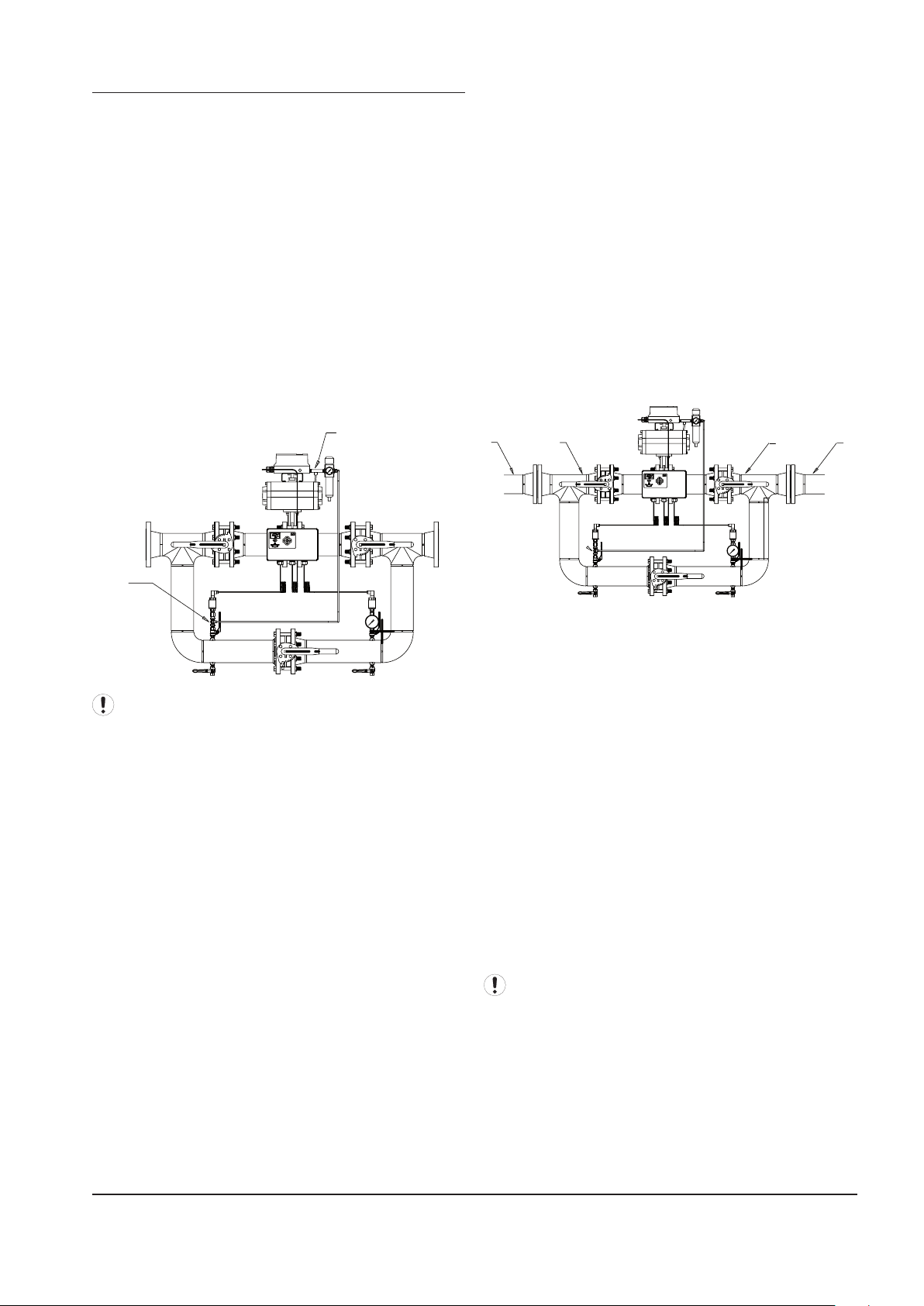
IX INTELLIFLOW INSTALLATION
B
A
B A BA
The IX IntelliFlow controller unit has been tested for
functionality and is ready for installation. Ingersoll
Rand recommends that a no-loss drain valve (CCN
38445920) be installed on the condensate drain valve
below the pressure transducer. (Other condensate drain
mechanisms can be installed/used. Consult Technical
Support or AfterMarket for assistance.) Inspect the unit
upon receipt. Immediately report any damage to the
shipping carrier.
FILTER INSTALLATION
The lter regulator assembly is shipped loose with
the IX controller. The assembly is packaged in a box
that is stored underneath the controller mounting
bracket. Please remove and mount as shown below
(A). The control air line for the lter assembly should be
connected to the tee tting connected to P3 (B).
MOUNTING POSITION & SUPPORT
The unit can be installed in any plane and is capable
of being installed vertically or horizontally. Additional
work is required when installing in the vertical mounting
position.
Horizontal Mounting
The unit is to be supported appropriately taking
into consideration the weight of the unit (reference
the respective drawings in the diagrams section for
approximate weights). Support should be provided
through:
The main piping (A) of the unit (not the control
A.
elements, the associated control piping, or valve
assemblies), and/or
The system piping (B).
B.
Consult Technical Support for further information.
•
Wire the unit in accordance with the wiring
•
schematic in the DIAGRAMS section of this manual.
Incoming power should be connected via the Gland
It may be necessary to add a drain line to the control
air lter to relieve buildup of condensate in the lter.
DIRECTION OF AIR FLOW
The unit has directional ow arrows. Orient the unit in
accordance with the compressed air ow system. The
factory unit is congured such that the air ows from
left to right when looking at the controller display. There
may be some cases when installing the IX IntelliFlow
unit where the air ows from right to left placing the
controller away from view. In these instances, re-mount
the bracket supporting the controller enclosure to the
opposite side of the IX IntelliFlow unit and rotate the
pressure gauge 180 degrees. Then mount the IntelliFlow
in the direction of the air ow (right to left). The air ow
will follow the air ow decals (entering on the P3 pressure
transducer side).
Holes using the necessary wire glands.
Fix any loose pre-wired connections.
•
Vertical Mounting
For vertical mounting, the pressure transducers and the
ltered pressure regulator are to be re-oriented 90˚.
The pressure transducers must be re-oriented such
•
that the body of the transducer is directed upwards.
The sensor cable should be on top of the sensor.
Additional elbows required to re-orient these devices
•
shall be eld supplied and installed.
o The ttings must be rated for 200 PSI (13.78
Bar) minumum.
It may be necessary to add a eld installed drain
connected at the bottom piping run to allow for proper
drainage of condensate that may collect in the piping.
ingersollrandproducts.com 9
Page 10
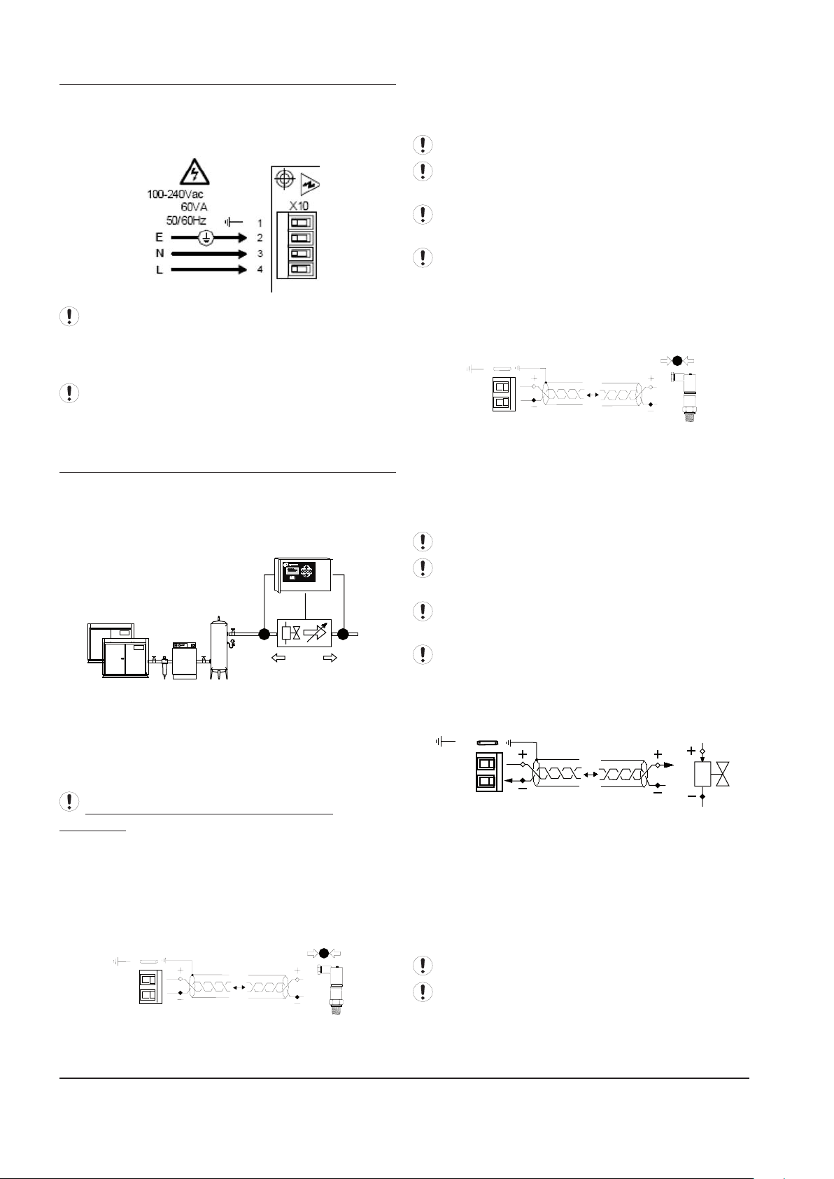
IX BOX POWER SUPPLY
X02 X01
X03
P4
P3
Ao
4-20m
A
100m (330ft) max
2
1
X01
+C
A
i1
P4
4-20mA
100m (330ft) max
2
1
X02
+C
A
i2
P3
4-20mA
100m (330ft) max
2
1
X03
Ao
A-GND
The IX IntelliFlow Controller Unit is equipped with a
power supply input that will accept 100Vac to 240Vac,
50/60Hz.
Before applying power to the IX IntelliFlow Controller
unit ensure that the power supply connections are
correct and secure and that the supply voltage is 100Vac
to 240Vac (+-10%), 50/60Hz.
Wiring run through the enclosure must be made
using Type 12 UL rated ttings which are eld provided.
pressure, Demand side or outlet side, of the IX IntelliFlow
Valve assembly. Use shielded (earth screened), twoconductor (2 core), 20 gauge (0.5mm2 CSA) minimum,
cable no greater than 330ft (100m) in length.
Connection polarity is important.
For ‘Backward’ mode it is not necessary to connect a
‘P4’ pressure sensor.
For ‘Forward’ or ‘Combination’ Modes a ‘P4’ sensor
must be connected.
Re-use electrical ttings provided for pressure
transducer wiring.
P3 Pressure Sensor, 4-20mA: For Supply Side / Back
Pressure / Backward Mode or Combination Demand /
Supply Side / Combination Mode Pressure Control.
IX INTELLIFLOW VALVE CONTROLLER
CONNECTION AND SENSOR ARRANGEMENT
The IX IntelliFlow assembly ships with both the P3 and
the P4 pressure transducers installed and prewired to
the IX controller inputs. The control valve positioner
is also prewired to the controller output.
P3 Supply Side, High Pressure Side (IX IntelliFlow
Inlet) pressure transducer.
P4 Demand Side, Low Pressure Side (IX IntelliFlow
Outlet) pressure transducer.
Ao Analog output to the IX Control Valve positioner.
If it is necessary to remote mount the IX
IntelliFlow controller, the following diagrams depict
the electrical connections between the controller, the
pressure transducers, and the control valve positioner.
P4 Pressure Sensor, 4-20mA: For Demand Side /
Forward Mode Pressure Control (Factory Default) or
Combination Demand / Supply Side / Combination
Mode Pressure Control (Optional)
Pressure Sensor ‘P3’ must be installed on the High
Pressure or inlet side, of the IX IntelliFlow Valve assembly.
Use shielded (earth screened), two-conductor (2 core),
20 gauge (0.5mm CSA) minimum, cable no greater than
330ft (100m) in length.
Connection polarity is important.
For ‘Forward’ mode it is not necessary to connect a ‘P3’
pressure sensor.
For ‘Backward’ or ‘Combination’ Modes a ‘P3’ sensor
must be connected.
Re-use electrical ttings provided for pressure
transducer wiring.
Valve Control Analog Output, 4-20mA: For Control of
the Control Valve Positioner
Connect the controller ‘Ao’ 4-20mA control output to the
valve 4-20mA input. Use shielded (earth screened), twoconductor (2 core), 20 gauge (0.5mm2 CSA) minimum,
cable no greater than 330ft (100m) in length.
The ‘Ao’ 4-20mA output is active at a voltage of 24VDC
(+-2VDC) and is intended for connection to devices with a
‘loop powered’ 4-20mA input.
Connection polarity is important.
Re-use electrical ttings provided for pressure
transducer wiring.
Pressure Sensor ‘P4’ must be installed on the Low
10 ingersollrandproducts.com
Page 11
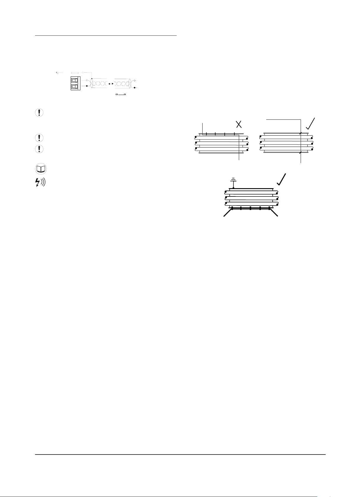
IX BOX RS485 NETWORK
2
1
+L1 (A)
RS485
-L2 (B)
+L1 (A)
-L2 (B)
X13
Modbus RTU or IRBus/RS485
The IX IntelliFlow Valve Controller is equipped with an
RS485 network communications capability using Modbus
RTU or being connected to the X-Series compressor
control products.
The cable used should be Belden 9841 (or equivalent).
It should be run in grounded conduit and should not be
greater than 4000 feet (1219 meters) in length.
Connection polarity is important.
Wiring run through the enclosure must be made
using Type 12 UL rated ttings which are eld provided.
Menus and Menu Items
RS485 data communications and other low voltage
signals can be subject to electrical interference. This
potential can result in intermittent malfunction or
anomaly that is dicult to diagnose. To avoid this
possibility always use earth shielded cables, securely
bonded to a known good earth at one end. In addition,
give careful consideration to cable routing during
installation.
a) Never route an RS485 data communications or
low voltage signal cable alongside a high voltage
or 3-phase power supply cable. If it is necessary
to cross the path of a power supply cable(s),
always cross at a right angle.
b) If it is necessary to follow the route of power
supply cables for a short distance, attach
the RS485 or signal cable on the outside of a
grounded (earthed) cable tray such that the
cable tray forms a grounded (earthed) electrical
interference shield.
c) Where possible, never route an RS485 or signal
cable near to equipment or devices that may be
a source of electrical interference (for example:
3-phase power supply transformer, high voltage
switchgear unit, frequency inverter drive module,
radio communications antenna).
ingersollrandproducts.com 11
Page 12
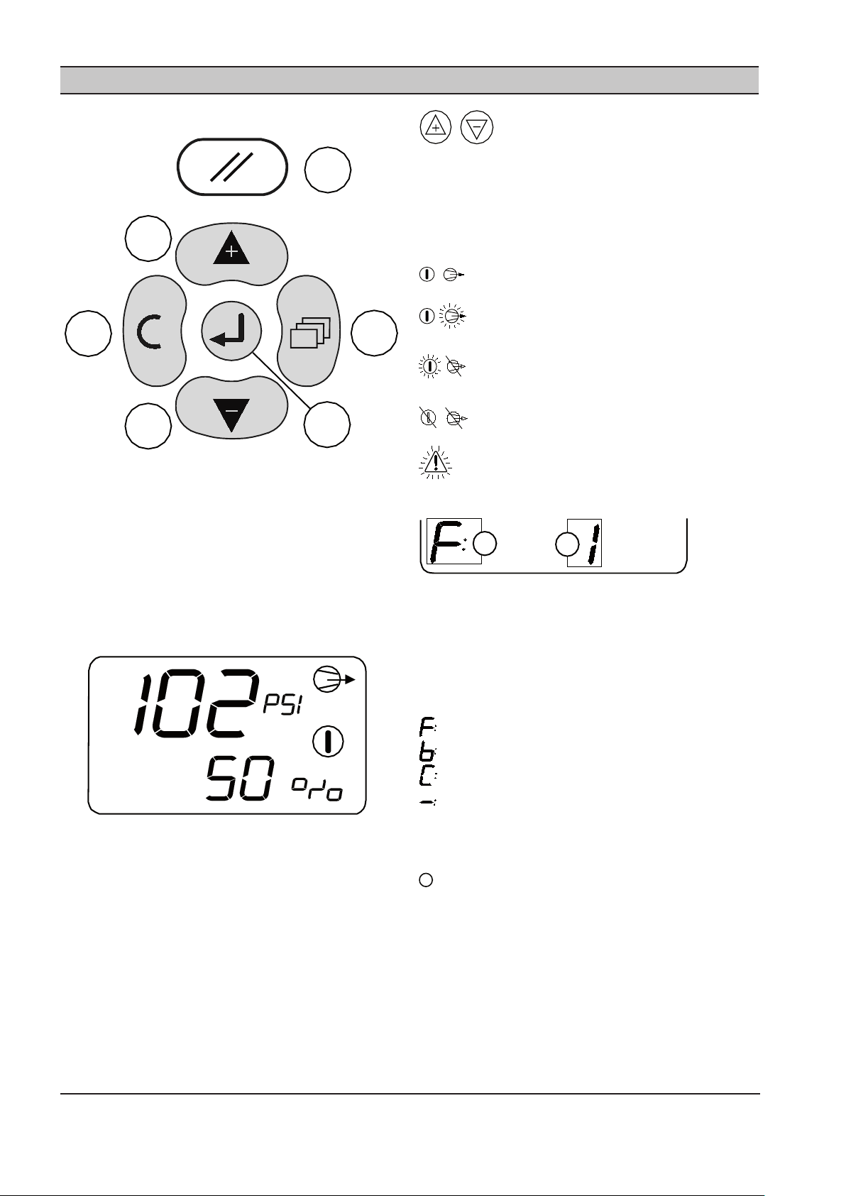
Keypad:
a
f
e
d
c
b
A
B
i
SECTION 7 DISPLAY AND MENU OPERATION
Press UP or DOWN to view other user menu
items.
The display will remain on the selected ‘User’ menu item
indenitely.
At power-up, or reset, the display will default to the rst
user menu list item.
Status Symbols:
ON/ON Operating
ON/Flash Manual Mode
Flash/OFF Forced Open/Closed
OFF/OFF Fault Shutdown
Reset
a)
Menu
b)
Enter
c)
Down (Minus)
d)
Up (Plus)
e)
Escape (Cancel)
f)
Display
Pressure = Main Display Pressure
% = Valve percentage open (0-100%)
The main display pressure is dependent on the Operating
mode or the Combi. Mode Display Pressure (1.dP) setting.
The Main Display Pressure will display the pressure value
as follows:
Forward Mode = P4 Pressure
Backwards Mode = P3 Pressure
Combination Mode = menu 1.dP setting
Manual Mode = menu 1.dP setting
Flash Fault
Status:
‘A’ = Active Target Pressure Setting
1, 2, 3 or 4 (1 = default)
Manual Mode = “-“(dash)
‘B’ = Mode
Forward Mode
Backward Mode
Combination Mode
Manual Mode
or Forced Closed
or Forced Open
see ‘Status Symbols’
12 ingersollrandproducts.com
Page 13
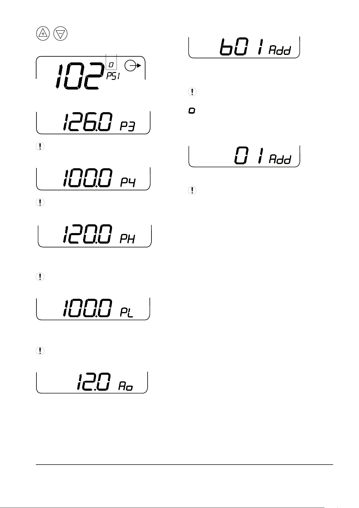
Press UP or DOWN to view other user menu
items.
P3 High Pressure, Generation Side, Inlet:
Only shown in ‘Forward’ mode if P3 sensor tted.
P4 Low Pressure, Demand Side, Outlet:
Only shown in ‘Backwards’ mode if P4 sensor tted.
Network Address (IRBUS Mode):
B01 = Network I/O Box number
In IRBUS Mode the IX Box simulates a network I/O Box.
For networks that have I/O Box(s) ensure the I/O Box
number is unique.
When the unit is detecting valid IRBUS
communications from the XI management system unit
the communications indicator symbol will show:
Network Address: Modbus Mode
Modbus Address – decimal 01 to 99
The communications indicator symbol will not show
in Modbus mode.
Active ‘High Target’ Pressure:
In accordance with the active target pressure H1, H2, H3
or H4
Not shown in Forward or Manual Mode.
Active ‘Low Target’ Pressure:
In accordance with the active target pressure L1, L2, L3 or
L4
Not shown in Backwards or Manual Mode.
Valve Control Output (4-20mA):
Example: 12.0 Ao = 12.0mA, 50%
ingersollrandproducts.com 13
Page 14
SECTION 8 COMMISSIONING
When commissioning the IX Box, carry out the following
procedures before attempting to start.
Menus and Menu Items
It is recommended that an authorized and trained
service technician perform the commissioning.
PHYSICAL CHECKS
1. Before applying power to the IX Box, ensure the
power supply connections are correct and secure
(115Vac or 230Vac (+-10%), 50/60Hz).
2. Open the front panel of the IX Box and ensure all
pressure sensor, RS485, and other connections are
correctly installed and secure.
See the section on Installation for more
information.
3. Close the front panel of the IX Box.
4. Switch on the power supply to the IX Box.
5. The control program identication will be displayed
for a short period followed by the normal operational
user display.
PRESSURE DISPLAY
Check the displayed delivery pressure. If the pressure is
incorrect, or inaccurate, check the type and range of the
sensor and carry out the pressure sensor commissioning
and calibration procedure.
3.3o P4 Outlet Pressure Oset
3.3r P4 Outlet Pressure Range
3.4o P3 Inlet Pressure Oset
3.4r P3 Inlet Pressure Range
User Conguration Menu 1
PRESSURE SET POINTS
Set the Forward Mode Target pressure set point to suit
system requirements in the appropriate control menu:
2.L1 Low Target Pressure #1
Menus and Menu Items
Target Conguration Menu 2
IX BOX OPTIONAL FEATURES AND
FUNCTIONS
Installation requirements may involve the
implementation of additional or optional functions and
features.
As default, additional optional functions and features
are deactivated or inhibited.
Features and Functions; Menu Items
IX INTELLIFLOW STARTUP
1. At initial start-up, begin with the bypass open.
2. Set the controller setpoint to a pressure at
the bottom of the Existing Upstream pressure
bandwidth. This will provide a changing system to
manually tune the control variables (proportional
pressure and integral time) and verify stable control.
See the Setting the Tuning Parameters section
for a description of how these values aect the
control system.
Menus and Menu Items
Sensor Calibration Menu 3
OPERATING MODE
Set the operating mode for the IX Box to Forward Mode in
the appropriate control menu:
1.oP Operating Mode
0: Forward Mode
This is the Default, As Shipped from the Factory,
Conguration
Set the Tuning Parameters for Forward Control mode in
the appropriate control menu:
1.3P P4 Proportional Pressure
Default is 20
1.3I P4 Integral Time
Default is 10
3. Slowly close the bypass.
4. Monitor the system and validate stable control. If
stable control is not achieved, open the bypass,
adjust control variables, and return to step 3.
Otherwise, continue to step 5.
5. Once stable control has been achieved, gradually
lower the setpoint until the optimal value has been
reached.
EXAMPLE:
Existing Upstream Pressure: 100-110 psi (6.9 to 7.6 bar)
Critical Pressure (minimum): 85 psi (5.8 bar)
1. Begin with the bypass valve fully open.
2. Set the controller setpoint to 100 psi (6.9 bar).
3. Slowly close the bypass valve.
4. If the control is not stable (valve is overshooting the
correct position or the setpoint is not being reached),
open the bypass, adjust the control variables, and
return to Step 3. If the control is stable, continue to
step 5.
14 ingersollrandproducts.com
Page 15

5. Gradually lower the setpoint (pausing to verify that
the control is still stable) until the optimal setpoint
has been reached.
In this example, the optimal setpoint might be 90 psi (6.2
bar) with the downstream pressure uctuating between
89.25 psi (6.1 bar) and 90.75 psi (6.25 bar) in regular
operation. This would provide a 5 psi (0.3 bar) safety that
would prevent the downstream pressure from going
below 85 psi (5.8 bar) in the event of a sudden change in
air demand or supply.
SETTING THE TUNING PARAMETERS
1.3P P4 Proportional Pressure
Default is 20
1.3I P4 Integral Time
Default is 10
PROPORTIONAL PRESSURE
Proportional control varies the signal sent to the valves
as a linear response to the dierence between the actual
system pressure and the system pressure setpoint. Valve
responsiveness can be adjusted through the IntelliFlow
Controller with the proportional pressure (1.3P.), setpoint.
This scaling factor is the amount of change in the input
variable (actual minus setpoint pressures) to cause a full
scale change in the output variable (valve position).
In other words, if the pressure in the air system uctuates
frequently, it would be prudent to set the proportional
pressure to a low value (a value / number greater than
the factory default of 20) to keep up with those system
changes. Otherwise, if the system is very stable, it would
be prudent to set the proportional pressure to a high
value (a value / number less than the factory default
of 20) to keep up with those system changes. The
proportional pressure is directly related to valve life and
indirectly related to valve cycling; so, as band decreases,
valve life decreases and cycling increases.
As stated earlier, the IntelliFlow Controller uses a
proportional plus integral control algorithm. The
result of proportional only control is oset from the
controlled variable discharge pressure. This means that
if the setpoint pressure is 100, the actual pressure may
only be 95. The value of this oset depends upon the
proportional pressure value.
What is the valve response when the dierence between
actual and setpoint pressures is zero? There is no
response. Proportional control only functions when a
dierence or error exists. Design discharge pressure could
not be attained in a proportional only control system.
Therefore, an integral control algorithm is added to
achieve the desired discharge pressure.
INTEGRAL TIME
The oset produced by the proportional control
algorithm could be eliminated by manually readjusting
the system pressure setpoint. Using the example above,
the setpoint could be reset to 105 to obtain the 100
desired. Manually resetting the setpoint would be
required as the system demand uctuated. Integral
control, also known as reset control, automatically resets
the desired system pressure setpoint. For the IntelliFlow
controller, the rate at which the controller resets the
system pressure setting is known as Integral Time, (1.3I.),
and is expressed in minutes between reset.
If precise control of the specied discharge pressure is
required, the Integral Time setpoint should be set for a
fast value. In other words, if the pressure in the air system
uctuates frequently, it would be prudent to set the
Integral Time to a high value (a value / number greater
than the factory default of 10) to keep up with those
system changes. Otherwise, if the system is very stable,
it would be prudent to set the Integral Time to a low
value (a value / number less than the factory default of
10) to keep up with those system changes. It is directly
related to valve life and inversely related to valve cycling,
so, as Integral Time increases, the valve life increases and
cycling decreases.
When band is low and Integral Time is fast, valve activity
is signicant in both magnitude and frequency to obtain
the desired setpoint. The other scenario, band is high and
Integral Time is slow, has relatively little valve activity, and
may never reach the setpoint position.
Proportional pressure and Integral Time are variables
used internally by the control system to determine
valve response and direction for a given compressed
air system. Each has an optimum value based upon the
system’s characteristics. Determining these optimum
values is a trial and error exercise. These setpoints should
be re-evaluated any time there is a major change in the
compressed air system.
ingersollrandproducts.com 15
Page 16
SECTION 9 SYSTEM CONFIGURATION
DISPLAY AND MENU OPERATION
All value, parameter or option selection displays are
grouped into menu lists. Items are assigned to a list
according to type and classication. Items that can be
used to select options or modify functions are assigned to
‘menu mode’ lists. Items that a User may require to view
during routine operation, detected pressure for example,
are assigned to the normal operational mode list.
Each menu has a unique access code. Only one menu can
be entered at a time.
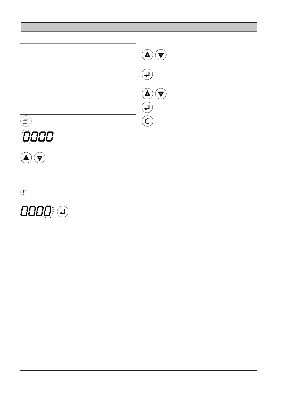
ACCESSING THE IX CONFIGURATION
SCREENS
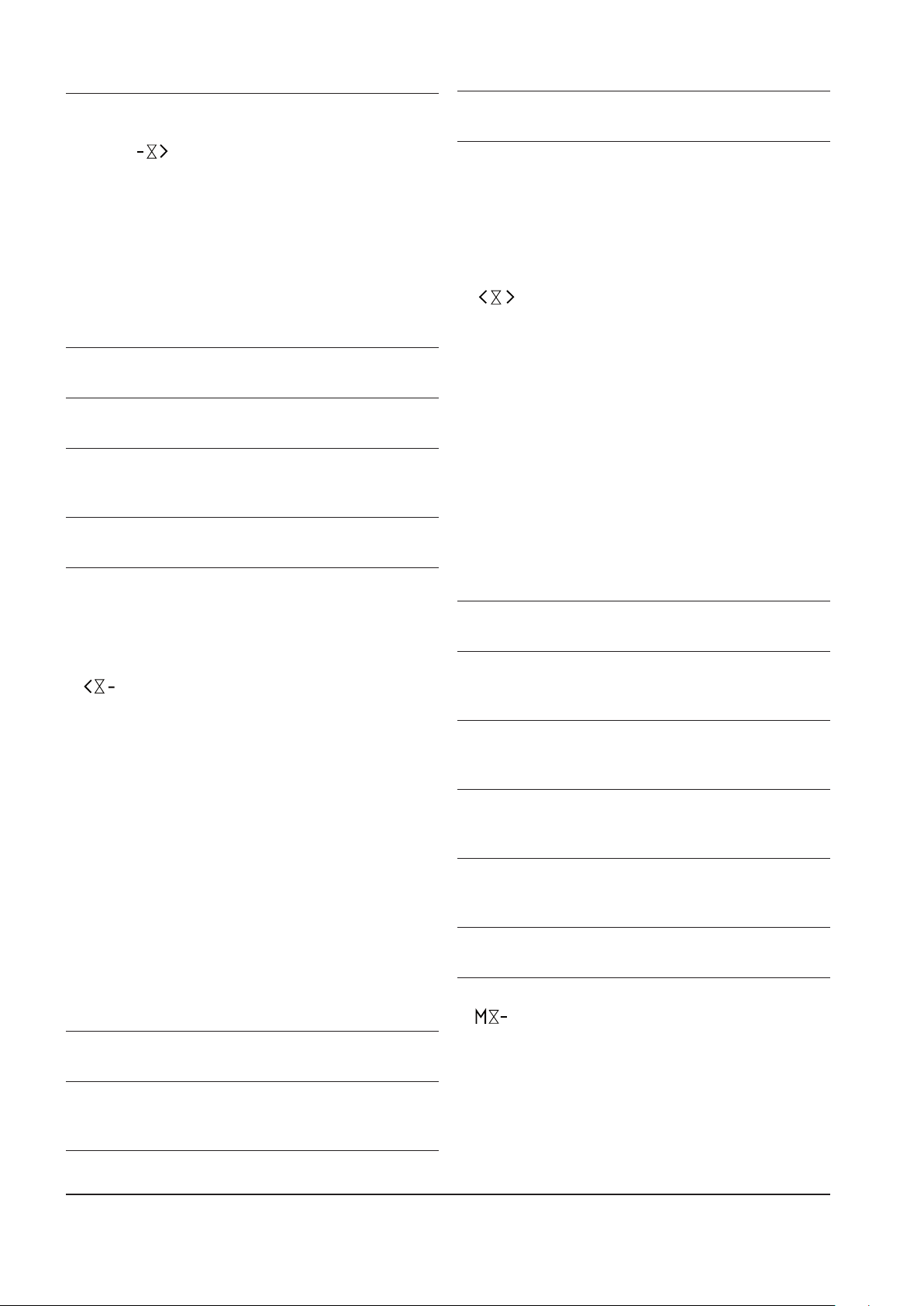
To access a menu press MENU.
The display will show four “0” characters;
the rst character will ash.
Press Up or Down to adjust the rst
character to match the rst character of the required
access code. If the access code number is ess than ‘1000’
the rst character will be ‘0’. Press Enter to increment to
the second code character.
code is incorrect the display will return to the normal
operational display.
To select a menu item for adjustment press
Up or Down until the menu item is displayed.
To adjust an item setting press Enter, the value or
option will ash.
Press Up or Down to adjust as required.
Press Enter to store in memory.
To exit the menu routine and return to the normal
operational display, at any time, press Cancel. The
display will return to the normal operational view. Any
adjustment that has not be entered to memory will be
abandoned and the previous setting maintained.
Menu codes are listed next to each Menu. See
Conguration Menu Overview for codes
When all four access code
characters have been set, and the last code character
is ashing, press Enter. If the access code is correct for
access to one of the accessible menus the rst menu item
of the appropriate menu will be displayed. If the access
16 ingersollrandproducts.com
Page 17
CONFIGURATION MENU OVERVIEW
1. - -
2. - -
3. - -
4. - -
5. - -
Each menu is accessed individually using the access
codes show.
User Conguration Menu 1
Menu Access Code ‘0011’
1.oP Operating Mode
1.3P P4 Proportional Pressure
1.3I P4 Integral Time
1.4P P3 Proportional Pressure
1.4I P3 Integral Time
1.bA Backwards Mode Algorithm
1.Po Manual Mode %Open
1.SP Maximum %Change/Second
1.LP Valve %Open Low Level
1.HP Valve %Open High Level
1.SF Control Pressure Fault Response
1.CF Communication Fault Response
1.Ad Network Address
1.Pd Pressure Display Unit
1.dP Combi. Mode Display Pressure
Target Conguration Menu 2
Menu Access Code ‘0021’
2.L1 Low Target Pressure #1 (default)
2.H1 High Target Pressure #1 (default)
2.L2 Low Target Pressure #2
2.H2 High Target Pressure #2
2.L3 Low Target Pressure #3
2.H3 High Target Pressure #3
2.L4 Low Target Pressure #4
2.H4 High Target Pressure #4
Relay Functions R1 to R6
Menu Access Code ‘0041’ (R1) to ‘0046’ (R6)
4.F1 Input Function #1 (A, b and C)
4.F2 Input Function #2 (A, b and C)
4.Fu Logic Function
4.on On Delay Time
4.oF O Delay Time
4.St Normal State
4.CF RS485 Failure Response
Diagnostic Menu 5
Menu Access Code ‘0051’
5.d1 Digital Input #1 (Di 1)
5.d2 Digital Input #2 (Di 2)
5.d3 Digital Input #3 (Di 3)
5.d4 Digital Input #4 (Di 4)
5.d5 Digital Input #5 (Di 5)
5.d6 Digital Input #6 (Di 6)
5.r1 Output Relay #1 (R1)
5.r2 Output Relay #2 (R2)
5.A1 Analog Input #1 (Ai1)
5.A2 Analog Input #2 (Ai2)
5.Ao Analog Output (Ao)
Sensor Calibration Menu 3
Menu Access Code ‘0031’
3.3o P4 Outlet Pressure Oset
3.3r P4 Outlet Pressure Range
3.4o P3 Inlet Pressure Oset
3.4r P3 Inlet Pressure Range
ingersollrandproducts.com 17
Page 18
USER CONFIGURATION MENU 1
1.oP – Operating Mode
There are 5 Operating Modes for the IX IntelliFlow control.
0: Forward Mode
P4 pressure sensor (Outlet, Low pressure, Demand Side) is
used for Control Pressure in accordance with active ‘Low
Target’ (2.L1 to 2.L4) pressure set point. The ‘High Target’
(2.H1 to 2.H4) pressure set points are inhibited and any P3
pressure sensor fault is ignored.
The valve will regulate using the P4 pressure in
accordance with the ‘1.4P’ proportional pressure and ‘1.4I’
integral time settings.
Forward Mode Control action is:
Target is 95psi (6.55 bar)
If P3 remains above 95psi (6.55 bar):
P4 is maintained at P4 target:
If demand increases and P4 falls below 95psi (6.55 Bar):
Valve opens towards 100%
If demand decreases and P4 increases above 95psi (6.55
Bar):
Valve closes towards 0%
If P3 falls below 95psi (6.55 Bar):
Valve will open 100% and P4 pressure will equal
P3 pressure
This mode of operation is intended to maintain a constant
Demand, or Outlet, side pressure where the Generation,
or Inlet, is at a higher pressure level.
1: Backward Mode
P3 pressure sensor (Inlet, High Pressure, Generation Side)
is used for Control Pressure in accordance with active
‘High Target’ (2.H1 to 2.H4) pressure set point. The ‘Low
Target’ (2.L1 to 2.L4) pressure set points are inhibited and
any P4 pressure sensor fault is ignored.
If ‘1.bA = 0’:
The ‘1.4P’ (P4 Proportional Pressure) and ‘1.4I’ (P4 Integral
Time) algorithm parameters are used.
If ‘1.bA = 1’:
The ‘1.3P’ (P3 Proportional Pressure) and ‘1.3I’ (P3 Integral
Time) algorithm parameters are used.
The valve will regulate using the P3 (Inlet, High Pressure,
Generation Side) pressure sensor in accordance with
the applicable ‘Proportional’ pressure and ‘Integral’ time
settings.
Backward Mode Control action is:
Target is 80psi (5.51 bar)
If P3 remains above 80psi (5.51 bar):
Valve remains fully open and P4 pressure will
equal P3 pressure.
If P3 falls to 80psi (5.51 bar):
P3 is protected from falling below 80psi:
If P3 falls below 80psi (5.51 bar):
Valve closes towards 0%
If P3 increases above 80psi (5.51 bar):
Valve opens towards 100% and P4 pressure will
equal P3 pressure.
This mode of operation is intended to ensure a minimum
specied Generation, or Inlet, side pressure is maintained
in instances where air demand from the Demand side,
or Outlet, becomes excessive and Demand side pressure
begins to decay.
2: Combination Mode
Both the P4 (Outlet, Low pressure, Demand Side) and the
P3 (Inlet, High Pressure, Generation Side) pressure sensors
are used for control. The ‘Forward’ mode and ‘Backwards’
mode control algorithms operate together at the same
time. Whichever control loop algorithm produces the
lowest %Open value will take priority; the valve will follow
the lowest %Open value.
In Combination mode, the operation and use of the valve
is dependent on the relationship between the set ‘Low
Target’ and ‘High Target’ pressure set points.
Backward Mode Control action is:
P4 target is 95psi (6.55 bar)
P3 target is 80psi (5.51 bar)
If P3 remains above 95psi (6.55 bar):
P4 is maintained at P4 target:
If demand increases and P4 falls below 95psi (6.55 bar)
Valve opens towards 100%
If demand decreases and P4 increases above 95psi (6.55
bar):
Valve closes towards 0%
If P3 falls below 95psi (6.55 bar) but remains above 80psi
(5.51 bar):
Valve will open 100% and P4 pressure will equal
P3 pressure.
If P3 falls to 80psi (5.51 bar):
P3 is protected from falling below 80psi (5.51
bar):
If P3 falls below 80psi (5.51 bar):
Valve closes towards 0%
If P3 increases above 80psi (5.51 bar):
Valve opens towards 100%
3: Manual Mode
The valve will open to the percentage open value
specied in ‘1.Po’. The valve will remain xed at this
%Open value regardless of target pressure set points,
variation in detected pressure, pressure sensor availability
or sensor fault state condition.
18 ingersollrandproducts.com
Page 19

4: Forced Closed
The valve is forced ‘Closed’. P3 and P4 pressure sensor
faults are ignored. When ‘Force Closed’ is activated the
valve will close immediately in accordance with the set
‘1.SP’ percent change per second limit. The ‘1.SP’ setting
restricts how fast the valve will close.
1.LP Valve %Open Low Level
If valve %Open < set ‘1.LP’; then Ai#3 ‘S’ state is set to ‘1’.
Ai#3 ‘S’ state will return to ‘0’ if valve %Open >= ‘1.LP’.
This setting has no eect on valve operation or %Open
position but can be used in local and/or system wide
‘Virtual Relay’ automation.
5: Forced Open
The valve is forced ‘Open’. P3 and P4 pressure sensor
faults are ignored. When ‘Force Open’ is activated the
valve will open immediately in accordance with the set
‘1.SP’ percent change per second limit. The ‘1.SP’ setting
restricts how fast the valve will open.
1.3P P3 Proportional Pressure Factor
The pressure range, above and below the set ‘target’
pressure, where integral control will occur.
1.3I P3 Integral Time Factor
The time that the output will execute a full scale change
from 4mA to 20mA, 0-100% (or vice versa).
1.4P P4 Proportional Pressure Factor
The pressure range, above and below the set ‘target’
pressure, where integral control will occur.
1.4I P4 Integral Time Factor
The time that the output will execute a full scale change
from 4mA to 20mA, 0-100% (or vice versa).
1.bA Backwards Mode Algorithm
0 - The ‘1.4P’ (P4 Proportional Pressure) and ‘1.4I’
(P4 Integral Time) algorithm parameters are used
for ‘Backwards’ mode operation.
1 - The ‘1.3P’ (P3 Proportional Pressure) and ‘1.3I’ (P3
Integral Time) algorithm parameters are used
for ‘Backwards’ mode operation (default).
1.HP Valve %Open High Level
If valve %Open > set ‘1.HP’; then Ai#4 ‘S’ state is set to ‘1’.
Ai#4 ‘S’ state will return to ‘0’ if valve %Open <= ‘1.HP’.
This setting has no eect on valve operation or %Open
position but can be used in local and/or system wide
‘Virtual Relay’ automation.
1.SF Control Pressure Fault Response
If a fault with the ‘Control’ pressure sensor occurs, or any
pressure sensor in Combination Mode:
0 - Manual Mode
1 - Force Valve Open (default)
2 - Force Valve Closed
1.CF Communications Fault Response
If a fault with network communications occurs:
0 – Continue normally (default)
1 – Force Valve Open
2 – Force Valve Closed
Only applicable in IRBUS Communications Mode; always
‘0’ (continue normally) in Modbus Mode.
1.Ad Network Address
Modbus:
01 to 99 decimal (0 to 63 Hex)
IRBUS Mode:
b01 to b12 (I/O Box 1 to 12)
1.Po Manual Mode %Open Value
Manual Mode %Open value (0 to 100%)
refer to ‘Manual Mode’ (1.oP)
1.SP %Change/Second
Restricts how fast the valve will open, or close, when
pressure changes abruptly and/or a signicant
‘Target’ pressure change is made. If the applicable, or
predominate, target algorithm produces a change in
%Open that exceeds the ‘1.SP’ setting the change in valve
%Open is restricted to the maximum % change
determined by the ‘1.SP’ setting until the required valve
%Open position is reached.
The ‘1.SP’ setting is expressed in %Change per second
where a setting of 20% will restrict any change to a
maximum of 20%Open per second - the valve will change
from fully open (100%Open) to fully closed (0%Open) in
ve seconds if the required %Open value changes from
100%Open to 0%Open abruptly.
‘1.SP’ is always active in all modes.
IRBUS or Modbus mode is selected automatically
dependant on set address.
1.Pd Pressure Display Units
0 – bar
1 - psi (default)
1.dP Combi. Mode Display Pressure
Determines if the P3 or P4 pressure is displayed as the
‘Main Display Pressure’ when operating in Combination
mode.
0 – P4 (default)
1 – P3
ingersollrandproducts.com 19
Page 20

PRESSURE TARGET MENU 2
2.L1 Low Target Pressure #1 (default)
Normal default outlet side target pressure when no
digital inputs are activated.
Active in ‘Forward’ and ‘Combination’ modes; not used for
‘Backwards’ mode.
2.H1 High Target Pressure #1 (default)
Normal default inlet side target pressure when no digital
inputs are activated.
Active in ‘Backwards’ and ‘Combination’ modes; not used
for ‘Forward’ mode.
2.L2 Low Target Pressure #2
Applicable when ‘Target Pressure Set 2’ digital input
activated.
Active in ‘Forward’ and ‘Combination’ modes; not used for
‘Backwards’ mode.
2.H2 High Target Pressure #2
Applicable when ‘Target Pressure Set 2’ digital input
activated.
Active in ‘Backwards’ and ‘Combination’ modes; not used
for ‘Forward’ mode.
2.L3 Low Target Pressure #3
Applicable when ‘Target Pressure Set 3’ digital input
activated.
Active in ‘Forward’ and ‘Combination’ modes; not used for
‘Backwards’ mode.
2.H3 High Target Pressure #3
Applicable when ‘Target Pressure Set 3’ digital input
activated.
Active in ‘Backwards’ and ‘Combination’ modes; not used
for ‘Forward’ mode.
2.L4 Low Target Pressure #4
Applicable when ‘Target Pressure Set 4’ digital input
activated.
Active in ‘Forward’ and ‘Combination’ modes; not used for
‘Backwards’ mode.
2.H4 High Target Pressure #4
Applicable when ‘Target Pressure Set 4’ digital input
activated.
Active in ‘Backwards’ and ‘Combination’ modes; not used
for ‘Forward’ mode.
If more than one digital input is activated the
following priority will apply:
1: (highest priority) Force Closed
2: Force Open
3: Manual Mode
4: Target Set #2
5: Target Set #3
6: (lowest priority) Target Set #4
SENSOR CALIBRATION MENU 3
3.3o P3 Pressure Sensor Oset
3.3r P3 Pressure Sensor Range
P3 pressure sensor (Inlet, High pressure, Generation Side)
calibration settings.
See ‘Pressure Sensor Calibration Procedure’
3.4o P4 Pressure Sensor Oset
3.4r P4 Pressure Sensor Range
P4 pressure sensor (Outlet, Low pressure, Demand Side)
calibration settings.
see ‘Pressure Sensor Calibration Procedure’
Pressure Sensor Calibration Procedure:
1) Commissioning
Initially set the ‘Oset’ (minimum) to the minimum or
lowest pressure value for the sensor. Set the ‘Range’
(maximum) to the maximum or highest value for the
sensor.
For example:
If the pressure sensor is a 0 to 232psi (0 to 16.0bar)
type set the ‘oset’ to 0psi (0bar) and the ‘Range’ to
232psi (16.0bar).
Execute the calibration procedure.
2) Calibration Procedure
a) Oset: Expose the sensor to atmosphere and adjust
the ‘oset’ setting (if necessary) until the detected
pressure display shows 0psi (0bar).
b) Range: Apply an accurately know pressure to the
pressure sensor and adjust the ‘Range’ setting until
the detected pressure display matches the applied
pressure. An applied pressure equal too, or greater
than, the nominal system working pressure is
recommended.
The detected pressure is displayed with the
calibration menu item and will change to match the
new calibration setting as the setting is adjusted.
There is no need for the applied pressure to be
static; it can be dynamic and changing. This enables
calibration to be carried out on a fully operational
system where changing system pressure can be
accurately veried from another source.
Correct pressure sensor set-up and calibration
is critical for successful system operation. It is
recommended that pressure sensor calibration is
examined, and adjusted if necessary, annually or a
pre-determined routine periodic basis.
RELAY CONFIGURATION MENU 4
see ‘Virtual Relay Automation’
20 ingersollrandproducts.com
Page 21
SECTION 10 DIAGNOSTICS
D1 Digital Input 1
D2 Digital Input 2
D3 Digital Input 3
D4 Digital Input 4
D5 Digital Input 5
D6 Digital Input 6
-------------------------------------------------------------
R1 Relay Output 1
R2 Relay Output 2
-------------------------------------------------------------
A1 Analog Input 1 psi <> mA
A2 Analog Input 2 psi <> mA
1: ON
0: OFF
OFF
ON
------------------------------------------------------------Ao Analog Output 0.0 to 20.0mA
DIAGNOSTIC MENU 5
The IX IntelliFlow Controller is equipped with
comprehensive diagnostic functions. Each input can be
examined individually and each output can be manually
activated or manipulated individually.
P2 Controller Diagnostics:
Reset All Settings To Default:
Enter an Access Code of ‘9750’; do not press enter when
the last character is ashing.
Press and hold CANCEL for 10 seconds; the controller will
reset and all settings will be reset to default. All previous
settings will be permanently lost.
Relay Outputs:
Each relay output can be energised and de-energised
manually by selecting the item. Use Up(plus) and
Down(minus) to adjust and Enter.
Analog Inputs:
The item will alternate between the detected value
and the electrical measurement on the controller input
terminals. An independent measuring device can be used
to check the displayed electrical measurement.
A1: P4 Outlet Pressure, 4-20mA
A2: P3 Inlet Pressure, 4-20mA
Analog Output:
The analog output can be manually adjusted to any
desired level. Press Enter then use Up (Plus) and Down
(Minus) to adjust and Enter. The output will return to
normal operational value upon menu exit.
ingersollrandproducts.com 21
Page 22
SECTION 11 FAULT CODES
In the event of a IX IntelliFlow IX Box Fault, the IX Box
display a fault code. The fault code becomes an item
in the User operational display menu. If more than one
active fault occurs each will be displayed as a separate
item in the operational User menu; press Up or Down to
view all active fault codes or to view the normal status
display.
Fault codes are separated in to A: Alarm (Warning) and E:
Shutdown Trip.
Pressure Sensor Faults:
Reaction to a pressure sensor fault is dependent on the
sensor and mode. If the pressure sensor is being used for
‘Control Pressure’, or the unit is in ‘Combination Mode’, the
controller will shutdown.
If the sensor is not being used for ‘Control Pressure’, and
the unit is not in ‘Combination Mode’, the sensor fault will
be ignored and the associating pressure display will show
“- - - -“ (dashes).
Fault Codes:
E0115 P4 Pressure Sensor Fault
E0125 P3 Pressure Sensor Fault
The unit’s controller has detected disruption to the
internal operational memory storage (RAM). The integrity
of the RAM memory contents is suspect; the controller
must be reset to clear and re-map the memory. Renew
the controller if this fault condition persists.
The controller’s main power supply must be removed and
re-applied to reset this condition.
Remote XI Management System Fault Code Display:
When set for an I/O Box address (b01 to b12) the XI
management system can be set to monitor the unit for
fault conditions.
B’nn’57 ‘nn’ = IO Box number (01 to 12)
P4 Demand Side Pressure Sensor Fault when operating in
Forward or Combination mode.
B’nn’58 ‘nn’ = IO Box number (01 to 12)
P3 Generation Side Pressure Sensor Fault when operating
in Backwards or Combination mode.
B’nn’60 ‘nn’ = IO Box number (01 to 12)
General Trip (Shutdown)
B’nn’ - - ‘nn’ = IO Box number (01 to 12)
RS485 communications disruption or loss.
E0821 Short Circuit
Short Circuit condition detected on the main controller
unit (digital inputs)
E0866 DC Power Supply Low
Check voltage of main power supply.
E5000 Internal Memory Map Error
When in IR485 mode, and connected to a network,
the ‘B’ fault codes can be monitored and displayed by an
XI system management unit. The ‘B’ codes do not show on
the IntelliFlow display.
22 ingersollrandproducts.com
Page 23
SECTION 12 IX INTELLIFLOW CONTROLLER PART LIST
3
20mm
5mm
IEC
1
253
160
90
2
A
B
205
253
4242
160 136
24
IX Box
Item Part No. Description
- 23451966 IX IntelliFlow
1 23451974 Unit, IX IntelliFlow
2 634067 Gland, Set - Pg13.5
- 80445588 Manual, User CD
ACCESSORIES:
Required For P3 and P4 System Pressure Transducers
Item Part No. Description
3 634065 Sensor, Pressure – Quantity (2)
4-20mA, 0-232 psi (0-16.0bar)
Item Part No. Description
2 634104 IEC Fuse T1.6A
SECTION 13 IX INTELLIFLOW CONTROLLER TECHNICAL DATA
Dimensions 10” x 6.3” x 3.6”
253 x 160 x 90mm
Weight 5.0lb (2.2kg)
Mounting wall, 2 x screw xings (8mm)
Enclosure IP54, NEMA 12
Supply 100 to 240Vac +/- 10%
Power 100VA
Temperature 32°F to 115°F (0°C to 46°C)
Humidity 95% RH, non-condensing
IX Box Technical Data
Mounting Dimensions (mm):
ingersollrandproducts.com 23
Page 24
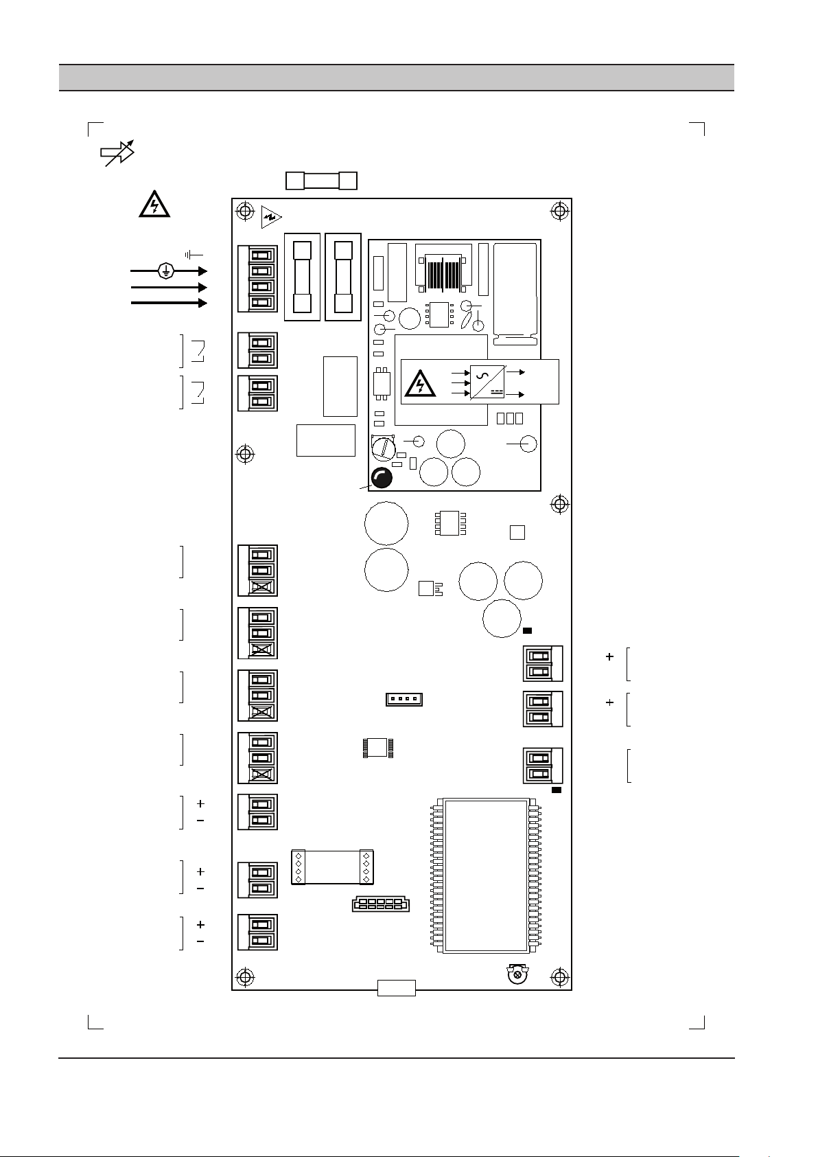
FH1
T1
.6
A
FH2
X10
T1
.6
A
PSU
IEC
20 x 5mm
LED1b
N
L
E
0VDC
+VDC
X09
X08
RL1
RL2
C01
Ai2
ACM
C018
RT1
X07
X06
X05
X04
X03
X02
X01
LCD
Ai2
C
Ai1
+C
Ao
A-GND
R1
R2
1
2
1
2
1
2
3
1
2
1
2
1
2
Di5
+C
Di6
D6
+C
+L1 (A)
RS
48
5
-L2 (B)
D5
2
1
2
1
2
1
4-20mA
4-20mA
4-20mA
Di4
GND
D4
+24 VDC
IR IntelliFlow Valv e
Control Unit - P2
100-240Vac
60VA
50/60Hz
1
2
3
4
E
L
N
X11
X12
X13
P2
4-20mA
LED2
LED1
+C
1
2
3
Di3
GND
D3
+24 VDC
+C
1
2
3
Di2
GND
D2
+24 VDC
+C
1
2
3
Di1
GND
D1
+24 VDC
+C
SECTION 14 IX INTELLIFLOW CONTROLLER WIRING DIAGRAM
24 ingersollrandproducts.com
Page 25
4-20mA
100m (330ft) max
1
2
3
1
2
3
1
2
3
1
2
3
1
2
Ai2
+C
2
1
1
2
+L1
2
1
0VDC
+24VDC
D1
+L1 (A)
RS485
-L2 (B)
+L1 (A)
-L2 (B)
-L2
RS485
X13
X02
X04
X05
X06
X07
Di1
+C
0VDC
+24VDC
D2
0VDC
+24VDC
D3
0VDC
+24VDC
D4
+24VDC
Ai2
4-20mA
100m (330ft) max
1
2
Ai1
+C
2
1
X01
+24VDC
Ai1
P4
P3
Target 2
Target 3
Target 4
Outlet
Demand Side
Inlet
Supply Side
330ft (100m) max
IR IntelliFlow Valve
Control Unit - P2
GND
Pressure
Pressure
Modbus
P2
L NE
X10
1 2 3 4
4-20mA
100m (330ft) max
1
2
A-GND
Ao
2
1
X03
Ao
A-GND
IntelliFlow Valve
4-20mA Output
Ao
100-240Vac
100VA
50/60Hz
Virtual Relay
Configurable
240V 'CE ' / 115V 'UL ' @ 4A
maximum.
1
2
1
2
R1
R2
X09
X08
Di6
+C
Di5
+C
1
2
1
2
+24VDC
D5
+24VDC
D6
X12
X11
Force Closed
Force Open
Manual Mode
X02 X01
X03
P4
P3
Ao
Di2
+C
GND
Di3
+C
GND
Di4
+C
GND
330ft (100m) max
330ft (100m) max
330ft (100m) max
330ft (100m) max
330ft (100m) max
ingersollrandproducts.com 25
Page 26
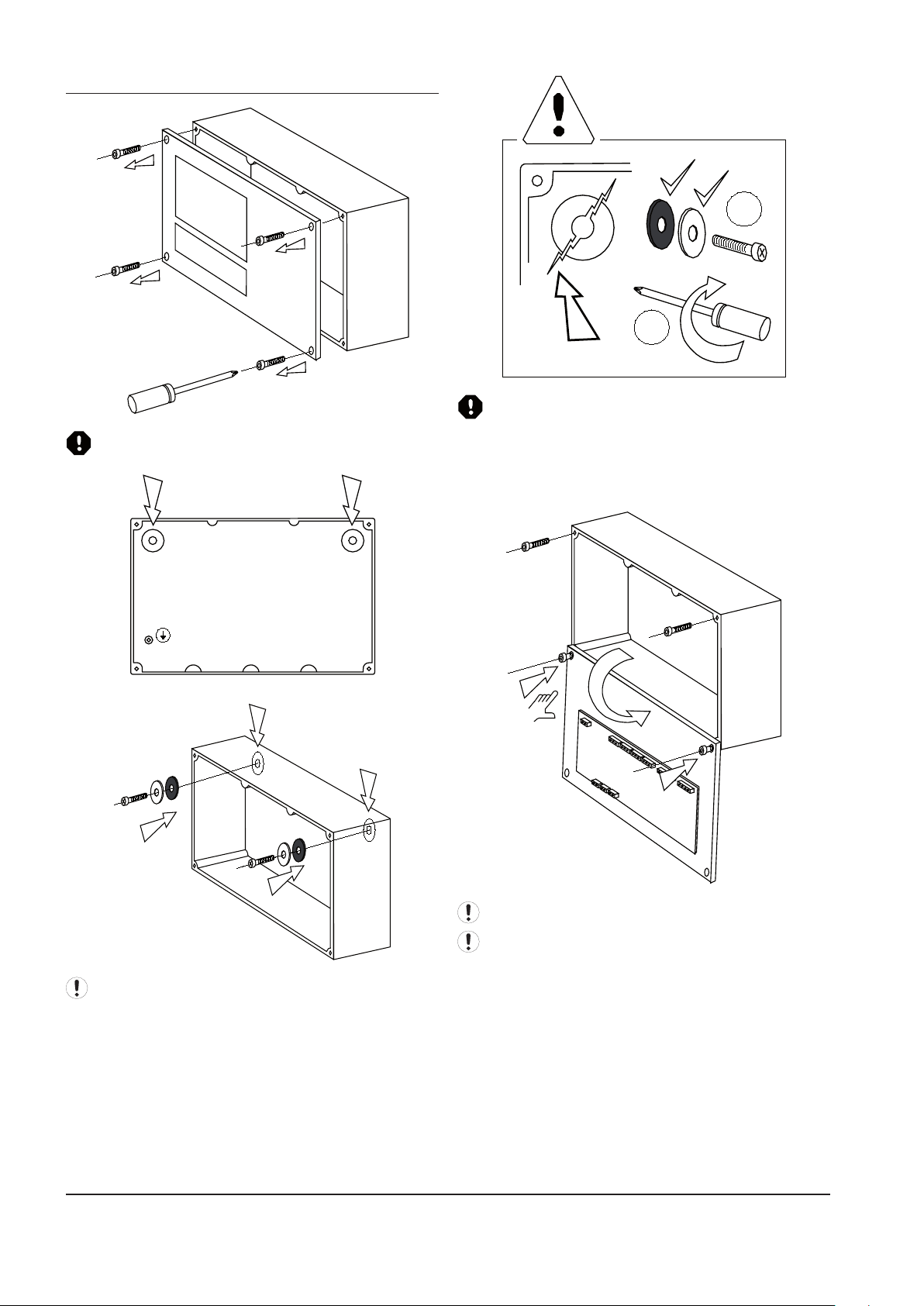
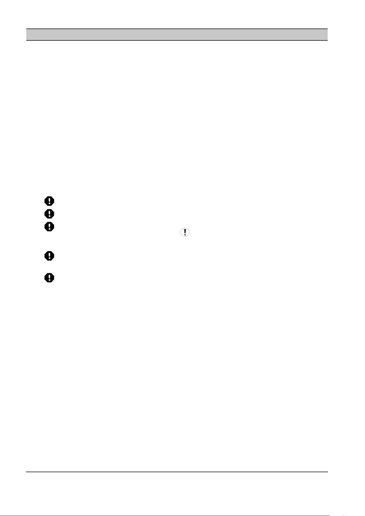
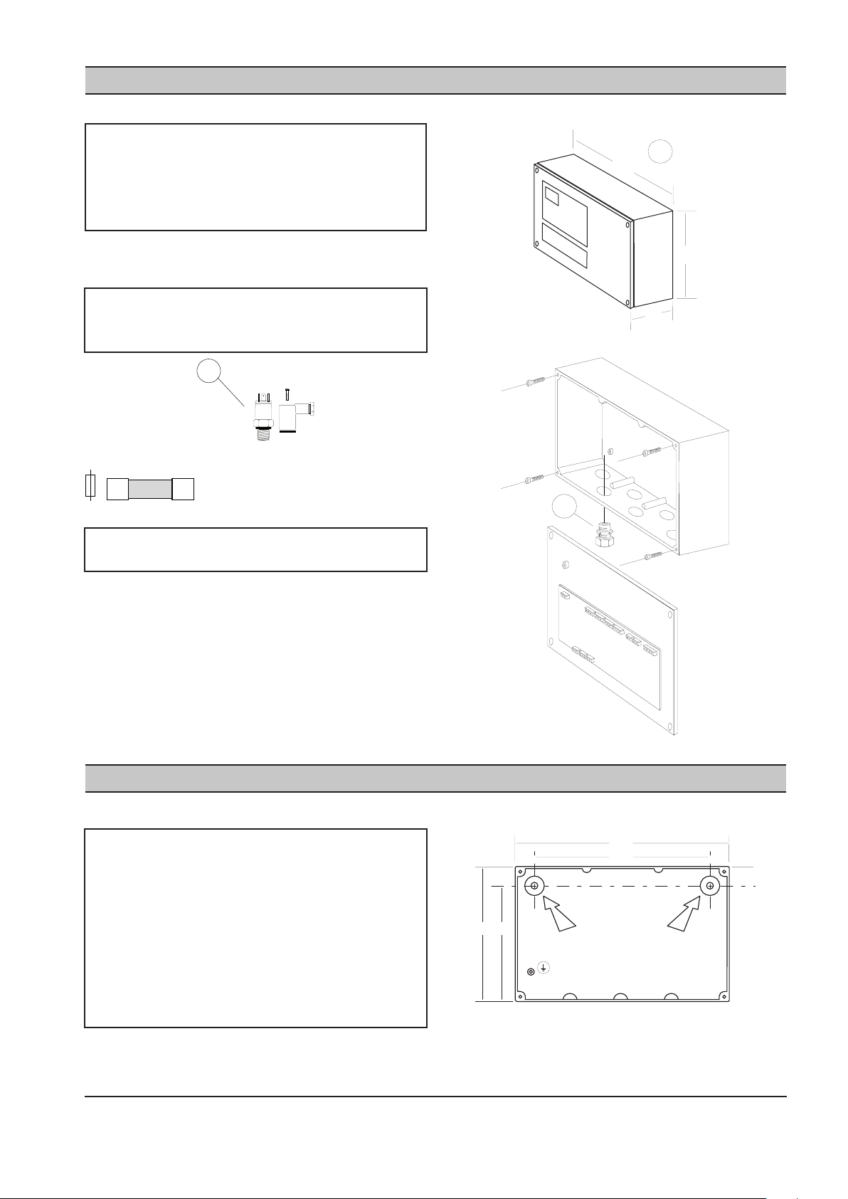
ENCLOSURE MOUNTING
A B
A
B
1
2
Use correct size Torrex Screw Driver
Excessive localized loading or force may fracture the
enclosure:
1. Always use mounting washes provide.
2. Do not over tighten mounting xtures.
See ‘Technical Data’ for enclosure and mounting
dimensions.
26 ingersollrandproducts.com
Cable Installation and Wire Connections:
Invert and secure front panel to the rear enclosure
lower front panel xings.
Page 27
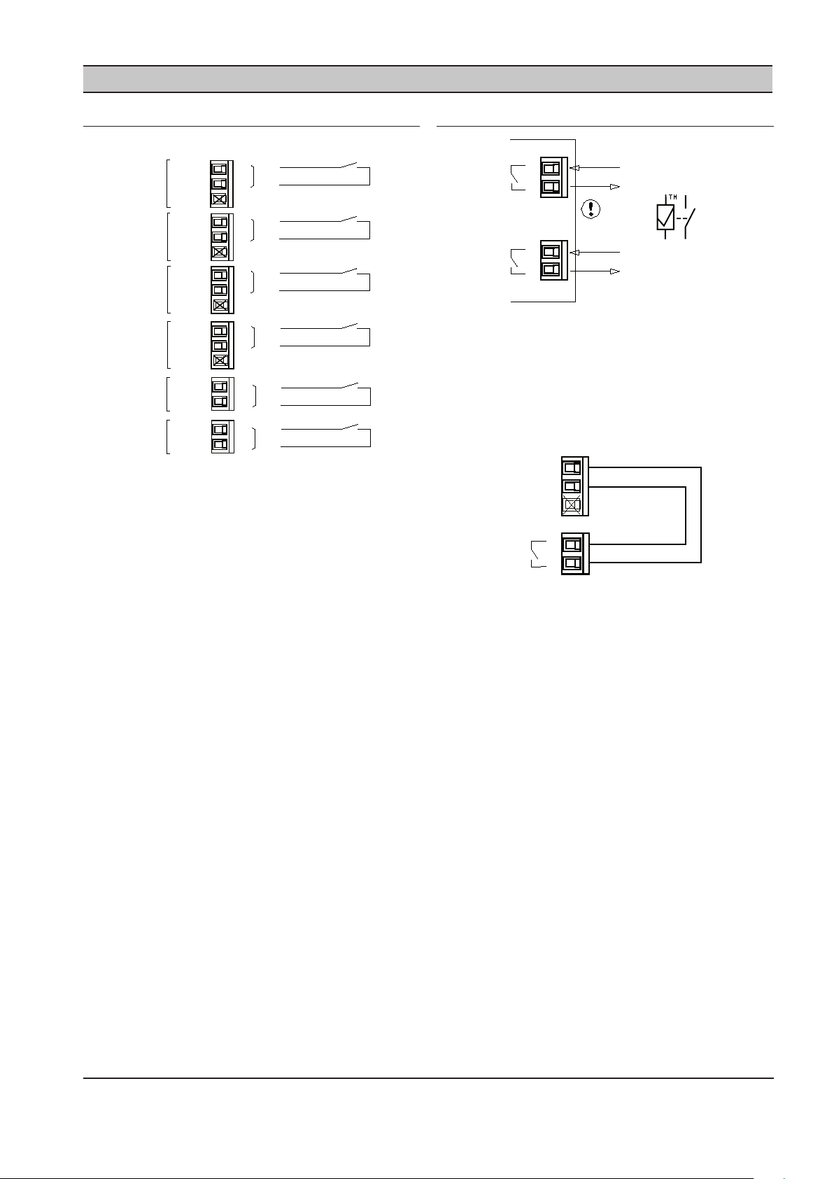
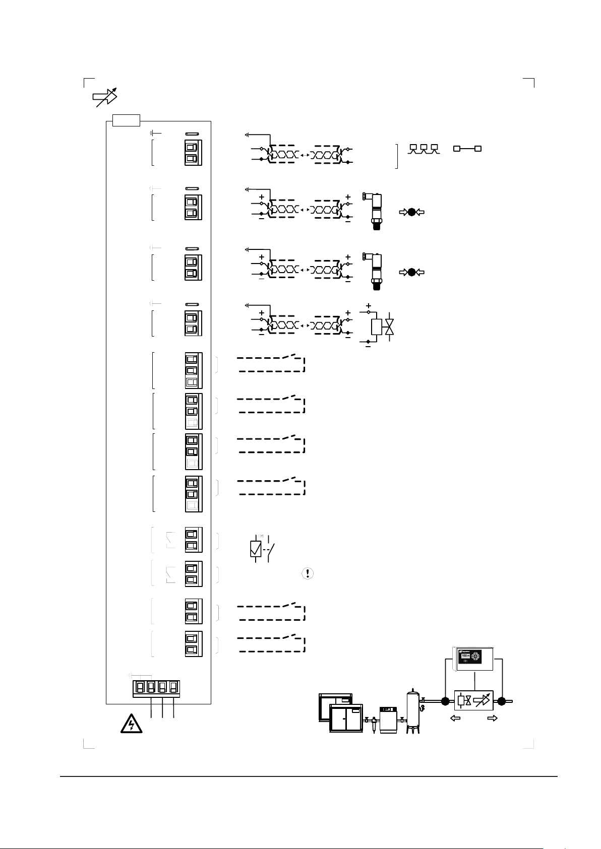
SECTION 15 IX INTELLIFLOW CONTROLLER REMOTE INPUTS
1
2
3
1
2
3
1
2
3
1
2
3
0VDC
+24VDC
D1
X04
X05
X06
X07
Di1
+C
0VDC
+24VDC
D2
0VDC
+24VDC
D3
0VDC
+24VDC
D4
T2
T3
T4
GND
M
Di2
+C
GND
Di3
+C
GND
Di4
+C
GND
Di6
+C
Di5
+C
1
2
1
2
+24VDC
D5
+24VDC
D6
X12
X11
FC
FO
330ft (100m) max
Virtual Relay
'CE' 240V @ 4A
'UL' 115V @ 4A
1
2
1
2
R1
R2
X09
X08
1
2
R1
X08
1
2
3
0VDC
+24VDC
D4
X07
M
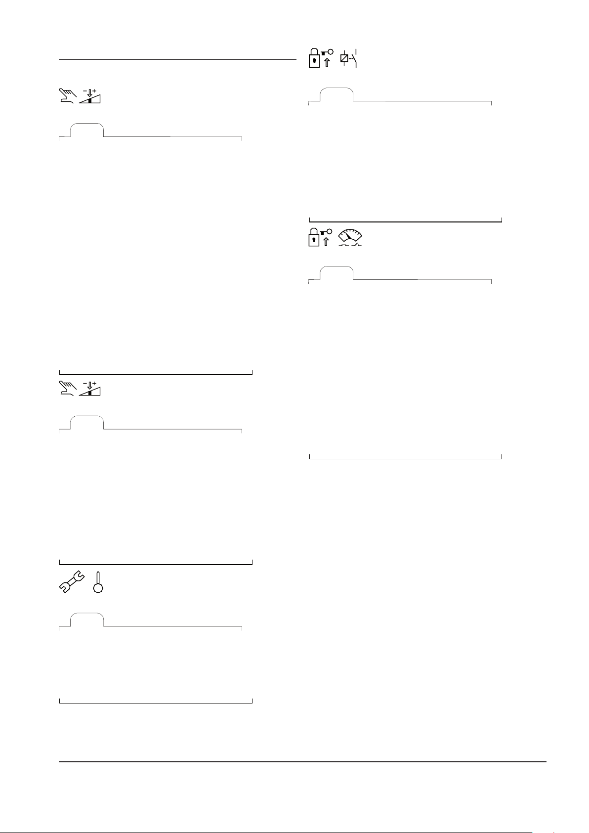
IX BOX INPUT FUNCTIONS
Remote ‘Volt-Free’ Switching Contact:
Use 20 gauge (0.5mm CSA) minimum, cable conductors
no greater than 330ft (100m) in length.
T2: Target Pressure Set Points #2
T3: Target Pressure Set Points #3
T4: Target Pressure Set Points #4
M: Manual Mode
FO: Force Open
FC: Force Closed
Remote inputs are intended for remote activation from a
‘volt-free’ switching contact, relay contact, PLC or other
remote logic device.
T2, T3 and T4:
When no ‘target pressure set’ digital inputs (Di1 to Di3) are
activated the controller will use ‘Target Pressure Set #1’.
VIRTUAL RELAY AUTOMATION
The target pressure set (2, 3 or 4), manual mode or force
closed/open selection inputs can also be activated by
the IntelliFlow ‘Virtual Relay’ automation functions by
connecting the appropriate ‘Virtual Relay’ output (R1 or
R2) to the required digital input.
For example:
Virtual Relay output R1 (X08) will activate Manual Mode
(X07).
Combinations of logic involving ‘Virtual Relay’ automation
output(s) and remote switching ‘volt-free’ contact(s) of
other third party devices can be implemented using this
methodology.
Remote Input Priority:
If more than one digital input is activated at the same
time the following priority will apply:
1 (highest priority): Force Closed
2: Force Open
3: Manual Mode
4: Target Set #2
5: Target Set #3
6: (lowest priority): Target Set #4
For example:
If the ‘Force Open’ and ‘Target Set #3’ inputs are both
activated together the unit will respond to the ‘Force
Open’ input.
ingersollrandproducts.com 27
Page 28

SECTION 16 IX INTELLIFLOW CONTROLLER RS485 MODBUS REGISTERS
Modbus RTU Protocol @ 9600, N-8-1
Registers 400XX:
‘XX’ Item, Description
01 Status (R)
Bits:
0 - Forward Mode
1 - Backwards Mode
2 - Combination Mode
3 - Manual Mode
4 - Forced Closed
5 - Forced Open
6 - Control Sensor Fault
7 - General Fault Shutdown
(including control sensor fault)
02 P4 Outlet Pressure, psi (R)
03 P3 Inlet Pressure, psi (R)
04 Valve %Open x 100
0 to 10000 = 0 to 100% (R)
05 Ao - mA x 100
400 to 2000 = 4.0 to 20.0mA (R)
06 Mode (R/W)
0 - Forward Mode
1 - Backward Mode
2 - Combination Mode
3 - Manual Mode
4 - Force Closed
5 - Force Open
07 L1: Low Target #1, psi (R/W)
08 H1: High Target #1, psi (R/W)
09 L2: Low Target #2, psi (R/W)
10 H2: High Target #2, psi (R/W)
11 L3: Low Target #3, psi (R/W)
12 H3: High Target #3, psi (R/W)
13 L4: Low Target #4, psi (R/W)
14 H4: High Target #4, psi (R/W)
15 3P - P4 Proportional Pressure
mBar; 69mBar = 1psi (R/W)
16 3I - P4 Integral Time; secs (R/W)
17 4P - P3 Proportional Pressure (R/W)
mBar; 69mBar = 1psi (R/W)
18 4I - P3 Integral Time; secs (R/W)
19 BA - Backwards Mode Algorithm (0=3P/3I;
1=4P/4I) (R/W)
20 SP - Maximum %Change/Second
100 to 10000 = 1% to 100% (R/W)
21 LP - Valve %Open Low Level
0 to 10000 = 0% to 100% (R/W)
22 HP - Valve %Open High Level
0 to 10000 = 0% to 100% (R/W)
23 SF - Control Sensor Fault (R/W)
0 - manual mode
1 - force valve open
2 - force valve closed
24 CF - Comms Fault (R/W)
0 - continue operating
1 - force valve open
2 - force valve closed
25 Manual Mode %Open value, ‘Po’
0 to 10000 = 0% to 100% (R/W)
(R) = Read Only
(R/W) = Read/Write
Read - function 03Hex
“01 03 00 00 00 01” Status Register
‘XX’ Register address has a ‘1’ oset:
For ‘Status’ (register address 01) use Hex address “00 00”
Write - function 06Hex only (single register)
“01 06 00 05 00 02” set Mode to Combination
‘XX’ Register address has a ‘1’ oset:
For ‘Mode’ (register address 06) use Hex address “00 05”
Mode - Write:
If the ‘P4’ sensor is not tted, or in a fault state, the
controller will not accept a command to change to
‘Forward’ or ‘Combination’ modes; a Modbus exception
response will be returned.
If the ‘P3’ sensor is not tted, or in a fault state, the
controller will not accept a command to change to
‘Backwards’ or ‘Combination’ modes; a Modbus exception
response will be returned.
28 ingersollrandproducts.com
Page 29
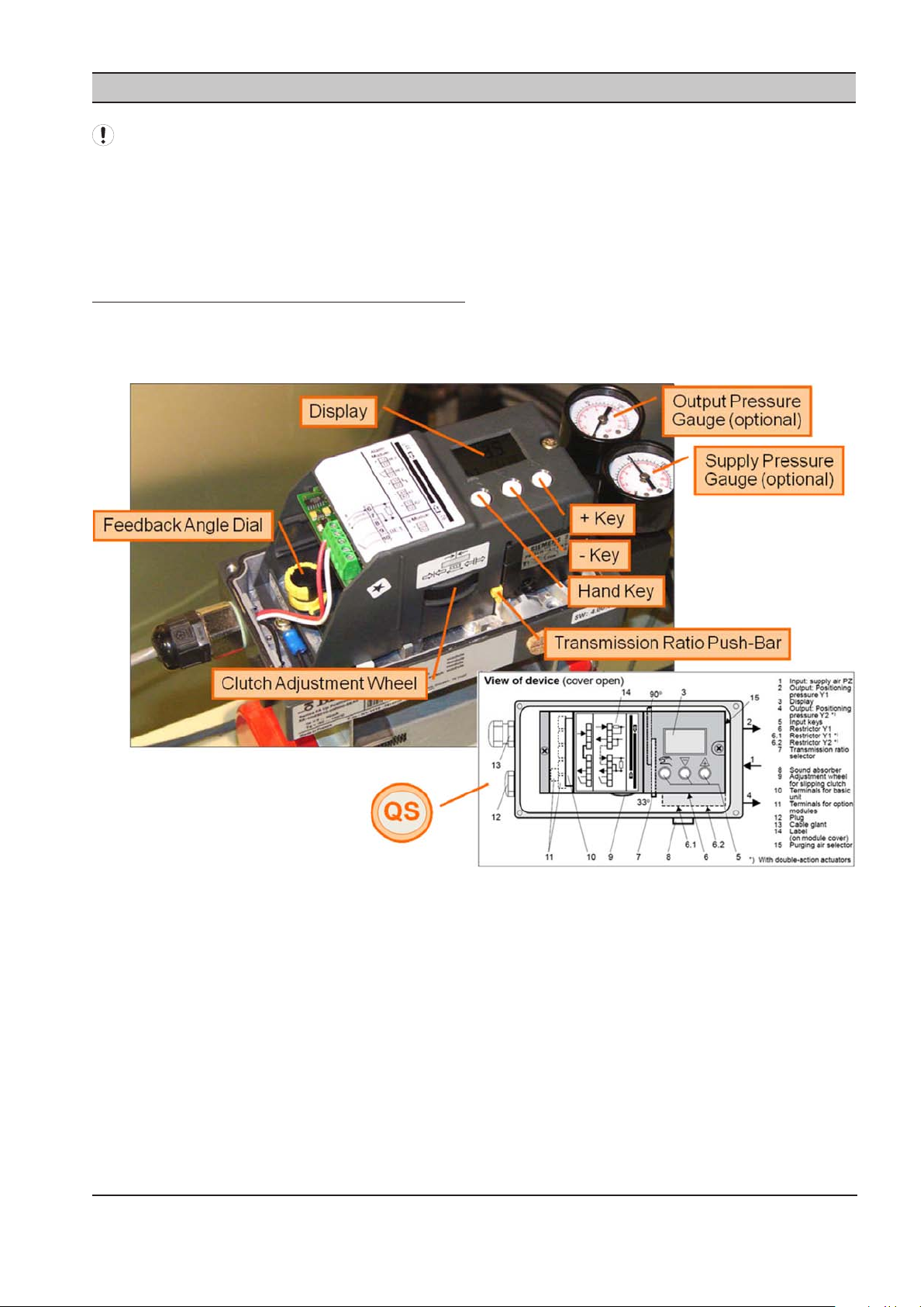
SECTION 17 IX INTELLIFLOW DIGITAL POSITIONER
The Digital I/P Positioner comes from the factory
pretested and fully calibrated and should not require
recalibration on new installations.
If the unit appears to need recalibration, please check
all pipe ttings and connections for air leaks prior to
performing the following calibration procedure.
IX INTELLIFLOW DIGITAL POSITIONER
SETUP PROCEDURE
Overview
Bray Series 6A (single-acting: only one output pressure)•
ingersollrandproducts.com 29
Page 30
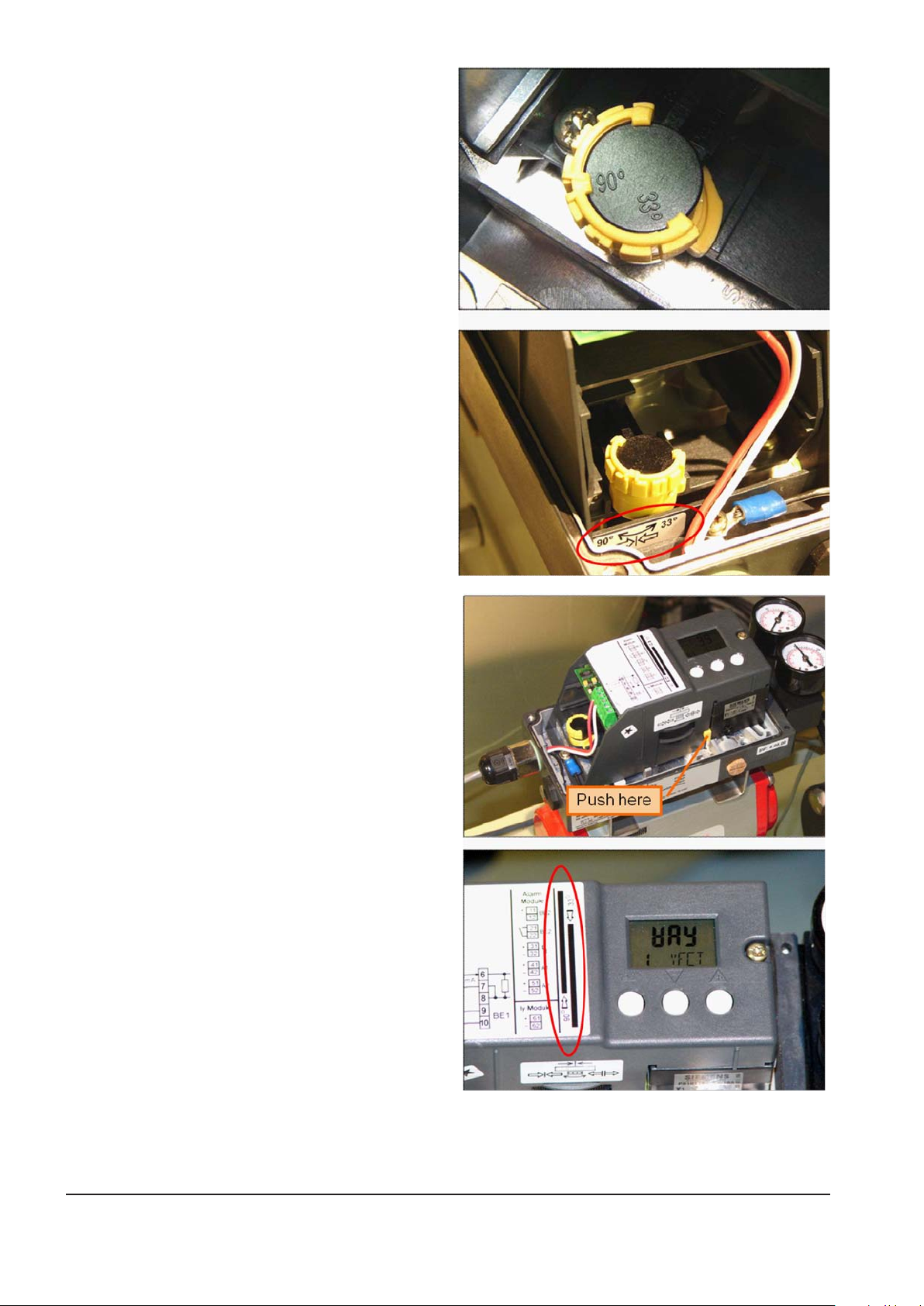
Feedback Angle Dial
Set to 90˚
•
o Rotate yellow outside c-ring clockwise until
center-mark is aligned with 90˚.
o The sticker below the dial indicates the correct
position for 90˚.
Transmission Ratio Push-Bar
Set to 90˚
•
o Push the Bar upwards from the bottom of the
unit.
o The sticker on top, by the display, indicates the
correct position for 90˚.
30 ingersollrandproducts.com
Page 31

Automatic Mode
The unit is normally in Automatic Mode when
•
power is rst applied.
º Hold in the Hand Key greater than 5 seconds to
go to Congure Mode.
º To go from Congure Mode back to Automatic
Mode:
Hold the Hand Key in greater than 5
seconds to reach Manual Mode.
Press the Hand Key once to go from
Manual Mode to Automatic Mode.
Congure Mode
Press the Hand Key to go to the next Parameter in
•
ascending order.
º Press the – Key while holding in
the Hand Key to go to the previous
Parameter (descending order).
Use the + and – Keys to change the value of a
•
Parameter.
º The following Parameters require the + Key to
be held greater than 5 seconds in order to start
their process:
PRST
INITA
ingersollrandproducts.com 31
Page 32

Congure Mode Parameters
Parameter used to set all others back to factory
•
settings:
o PRST
Critical Parameters to change / verify:
•
o YFCT
o YAGL
o SCUR
o SDIR
Parameter used for Automatic Initial Start-Up:
•
o INITA
Not all the Parameters on the map may be viewable;
meaning the Parameter numbers may not match (focus
on the Parameter name needed, not number).
32 ingersollrandproducts.com
Page 33

Preset Unit to Factory Settings
While in Congure Mode:
•
o Press the Hand Key repeatedly until the PRST
Parameter is displayed.
o Hold in the + Key until the Parameter Value
changes from Strt to oCAY.
Once oCAY is displayed, the Hand Key
can be pressed repeatedly to advance to
the Critical Parameters.
ingersollrandproducts.com 33
Page 34

Change / Verify Critical Parameters
While in Congure Mode.
•
o Press the Hand Key repeatedly until the YFCT
Parameter is displayed.
Press the – Key to change the Value to
turn.
o Press the Hand Key once to display the YAGL
Parameter.
o Verify the Value is set to 90˚ (change if it
is not).
34 ingersollrandproducts.com
Page 35

While in Congure Mode.
•
o Press the Hand Key repeatedly until the SCUR
parameter is displayed.
o Verify the Value is set to 4 nA (change if
it is not).
o Press the Hand Key once to display the SDIR
Parameter.
o Press the + Key to change the Value to
FALL.
ingersollrandproducts.com 35
Page 36

Automatic Initial Start-Up
Step 1 completed in previous steps.
•
Step 2:
•
o From SDIR Parameter (previous step), hold in
Hand Key and press – Key three times so INITA
Parameter is displayed.
o Start the process by holding in the + Key until
the Parameter changes from INITA to RUN 1.
Remaining steps are performed
automatically, wait until FINISH
is displayed.
Refer to the next slide if the following is
displayed:
36 ingersollrandproducts.com
Page 37
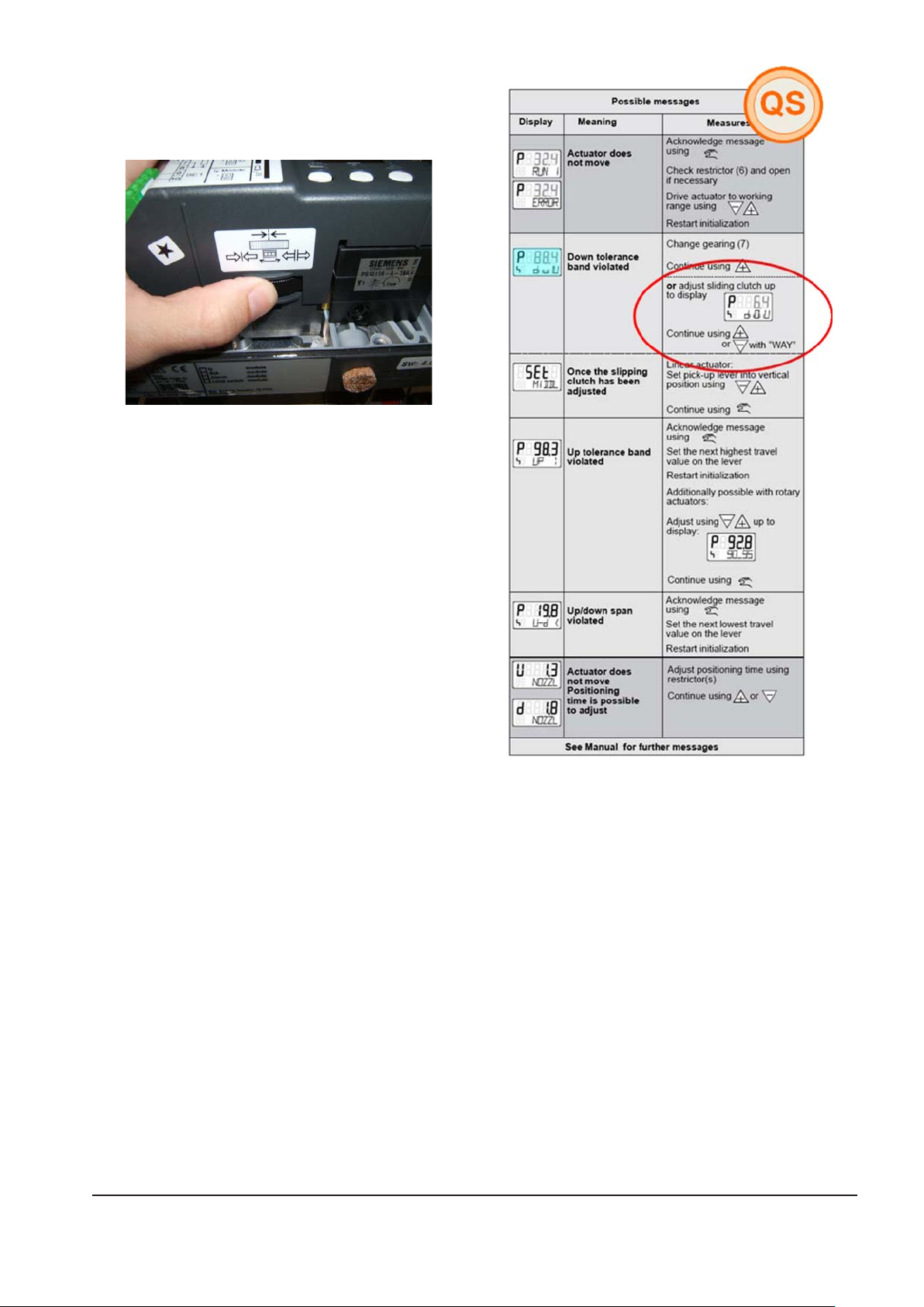
If the Down Tolerance Band Violated Display appears
•
during Automatic Initial Start-Up:
o Turn the Clutch Adjustment Wheel until the
Value displayed is as close to 6.4 as possible.
o Press the + Key once and then wait until FINSH is
displayed.
ingersollrandproducts.com 37
Page 38

After FINSH is displayed:
•
o Press the Hand Key once to get back to
Congure Mode.
o Hold in the Hand Key until VER is displayed. Once
the Hand Key is released, the unit will go to
Manual Mode.
o Press the Hand Key once to place the unit in
Automatic Mode.
Verify Positioner Calibration
Make sure the Positioner is in Automatic Mode.
•
Use the IntelliFlow’s IX Controller in Manual Mode to check the Positioner’s calibration (set Manual Mode to OFF
•
after completion):
o Set 1.Po Manual Mode %Open Value to 1:
Valve must be at 1% open, Positioner’s display must show a value close to 1.
o Set 1.Po Manual Mode %Open Value to 5:
Valve must open some from the 1% position, Positioner’s display must show a value close to 5.
o Set 1.Po Manual Mode %Open Value to 100:
Valve must be at 100% open, Positioner’s display must show a value close to 100.
o Set 1.Po Manual Mode %Open Value to 95:
Valve must close some from the 100% position, Positioner’s display must show a value close to 95.
If any of the conditions above do not occur, this Setup Procedure needs to be performed again starting at the
Feedback Angle Dial setup.
38 ingersollrandproducts.com
Page 39

SECTION 18 IX INTELLIFLOW ACTUATOR FAIL OPEN TO FAIL CLOSED
FAIL OPEN TO FAIL CLOSED PROCEDURE
The IX IntelliFlow assembly ships from the Factory as Fail
Open with the actuator being parallel to the pipe. In this
conguration, the control action is:
4mA the valve is open
20mA the valve is closed.
To change to Fail Close and reverse the Control action,
please perform the following steps.
1) Remove the 4 nuts from the studs that attach the
valve to the actuator.
2) Remove the actuator from the valve, please note that
there may be a stem adapter left in the actuator or
still in the valve stem.
3) Close the valve with a Crescent wrench (making sure
not to damage the stem or stem adapter.
4) Replace the actuator on the valve 90 degrees out
from the original position (Perpendicular to the
pipe).
5) Replace the nuts and lock washers, and tighten.
The valve is now Fail-Close. The Control action is:
4mA the valve is closed
20mA the valve is open.
ingersollrandproducts.com 39
Page 40

SECTION 19 IX INTELLIFLOW ASSEMBLY OVERVIEW DRAWING
FLOW DIREC TION
INLET CONNEC TION
150# RAISED FAC E
FLANGE
OUTLET CONNECTION
150# RAISED FAC E
FLANGE
DR AIN C ONNE CTION
1/4" NPT / G 1/4
ACTUATED CONTR OL
VALVE ASSEMBLY
CONTR OLLER
BYPASS VALVE
FLOW CONTR OL
PR ESSUR E GAUGE
BYPASS VALVE
DR AIN VALVE
ISOLATION
VALVE
PR ESSUR E
TR ANSDUC ER
FILTER R EGULATOR
& GAUGE ASSE MBLY
FRONT VIEW
TOP VIEW
SIDE VIEW
40 ingersollrandproducts.com
Page 41
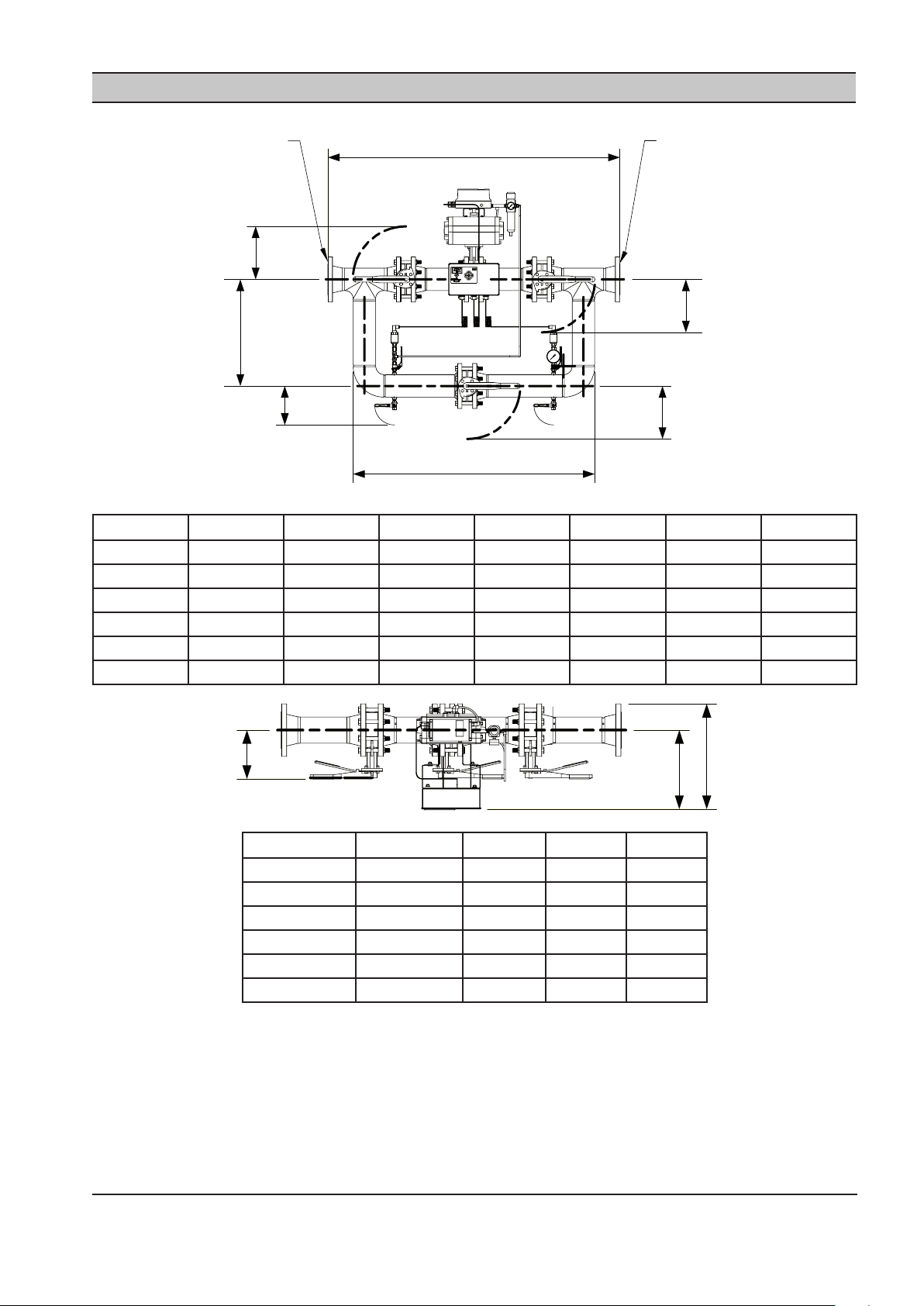
SECTION 20 IX INTELLIFLOW ASSEMBLY DIMENSIONS “INCHES”
( H )
BYPASS VALVE HANDLE
AT CLOSED POSITION
( J )
ISOLATION VALVE HANDLE
AT CLOSED POSITION
( H )
BYPASS VALVE HANDLE
AT CLOSED POSITION
( H )
BYPASS VALVE HANDLE
AT CLOSED POSITION
OUTLET CONNECTION “ P”
ANSI / DN PN10 RAISED
FACEFLANGE
INLET CONNECTION “ P”
ANSI / DN PN10 RAISED
FACEFLANGE
( E )
( D )
( A )
( N )
( G )
( C )
MODEL # CCN A D E H J P
IX02 23473192 39.25 31.62 14.75 10.62 7.00 2
IX03 23473200 43.87 34.75 18.12 10.62 7.50 3
IX04 23473218 58.50 48.37 21.37 10.62 8.00 4
IX06 23473226 64.50 52.50 25.50 10.62 9.06 6
IX08 23473234 70.68 56.93 24.75 11.75 10.06 8
IX08CDN 23485980 70.68 56.93 24.75 11.75 10.06 8
ingersollrandproducts.com 41
MODEL # CCN C G N
IX02 23473192 15.00 12.00 6.87
IX03 23473200 16.62 12.87 7.62
IX04 23473218 18.06 13.50 8.18
IX06 23473226 20.43 14.93 9.37
IX08 23473234 23.06 16.31 10.87
IX08CDN 23485980 23.06 16.31 10.87
Page 42

( M )
( F )
( B )
( L )
( K )
BYPASS VALVE HANDLE
AT CLOSED POSITION
CUSTOMER ELECTRICAL
CONNECTION
7/8 “ DIA. KNOCK OUT
*NOTES:
1) ALL DIMENSIONS ARE IN INCHES WITH A TOLERANCE OF +/- .25.
2) ALL WEIGHTS ARE IN POUNDS.
3) MAXIMUM PRESSURE RATING: 200 PSI.
4) MAXIMUM TEMPERATURE RATING: 150 DEG F.
MODEL # CCN B F K L M
IX02 23473192 33.87 15.37 4.00 10.25 12.00
IX03 23473200 38.50 16.00 4.00 11.00 15.37
IX04 23473218 44.25 18.12 4.00 11.75 18.50
IX06 23473226 51.25 19.87 4.00 13.12 22.75
IX08 23473234 53.06 21.37 4.00 14.50 22.00
IX08CDN 23485980 53.06 21.37 4.00 14.50 22.00
MODEL # CCN WEIGHT
IX02 23473192 180
IX03 23473200 260
IX04 23473218 440
IX06 23473226 650
IX08 23473234 860
IX08CDN 23485980 860
42 ingersollrandproducts.com
Page 43
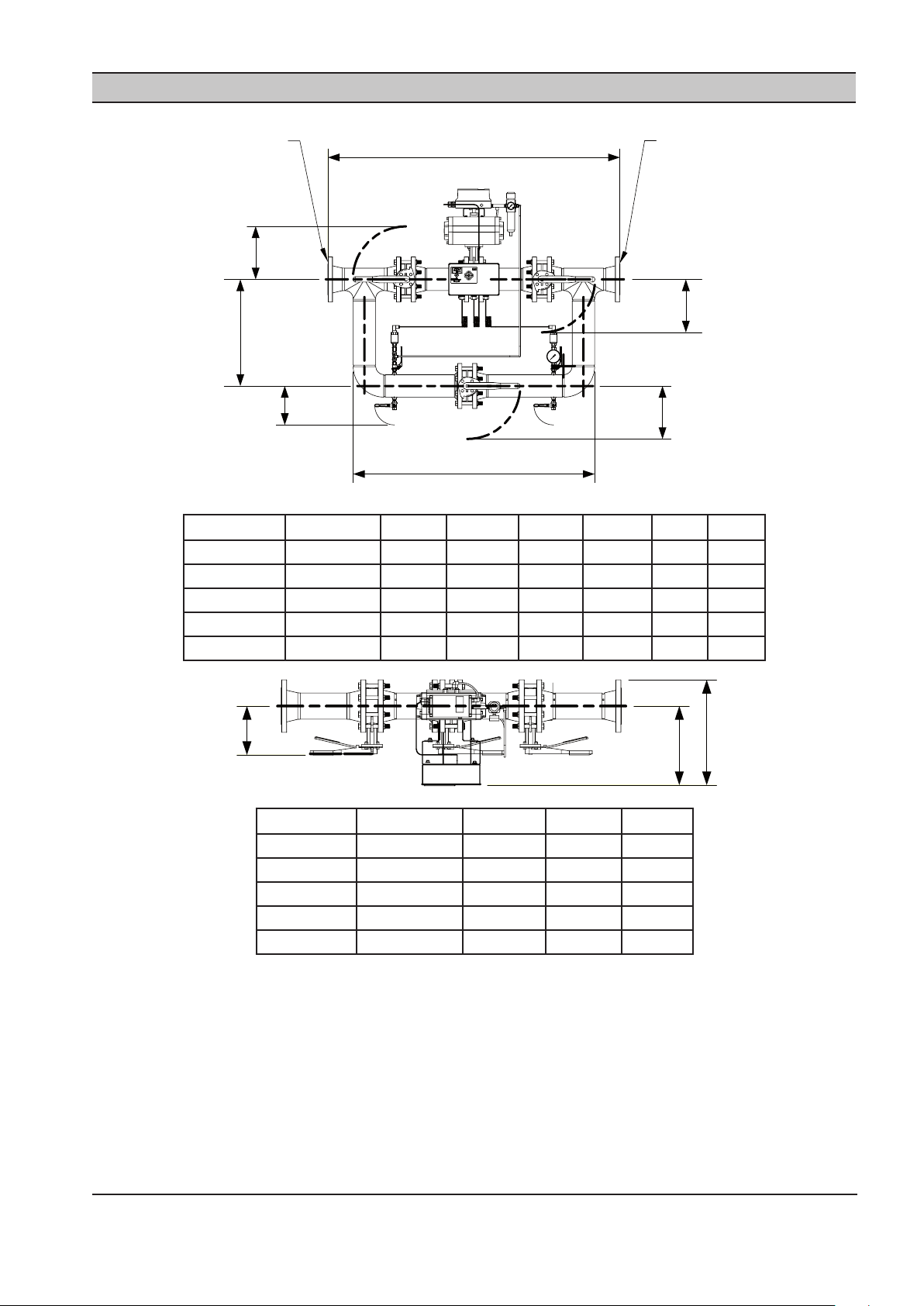
SECTION 21 IX INTELLIFLOW ASSEMBLY DIMENSIONS “MILLIMETER”
( H )
BYPASS VALVE HANDLE
AT CLOSED POSITION
( J )
ISOLATION VALVE HANDLE
AT CLOSED POSITION
( H )
BYPASS VALVE HANDLE
AT CLOSED POSITION
( H )
BYPASS VALVE HANDLE
AT CLOSED POSITION
OUTLET CONNECTION “ P”
ANSI / DN PN10 RAISED
FACEFLANGE
INLET CONNECTION “ P”
ANSI / DN PN10 RAISED
FACEFLANGE
( E )
( D )
( A )
( N )
( G )
( C )
MODEL # CCN A D E H J P
IX50 23473242 959 803 375 270 175 50
IX80 23473259 1075 883 460 270 192 80
IX100 23473267 1438 1229 543 270 202 100
IX150 23473275 1572 1334 648 270 231 150
IX200 23473283 1716 1446 629 299 256 200
ingersollrandproducts.com 43
MODEL # CCN C G N
IX50 23473242 387 305 175
IX80 23473259 427 327 194
IX100 23473267 459 345 213
IX150 23473275 522 380 238
IX200 23473283 586 414 276
Page 44
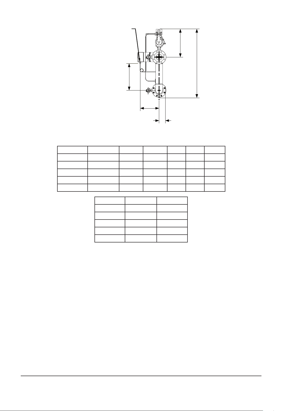
( M )
( F )
( B )
( L )
( K )
BYPASS VALVE HANDLE
AT CLOSED POSITION
CUSTOMER ELECTRICAL
CONNECTION
22,23mm DIA. KNOCK OUT
MODEL # CCN B F K L M
IX50 23473242 860 390 102 260 305
IX80 23473259 980 409 102 279 391
IX100 23473267 1003 460 102 298 470
IX150 23473275 1303 505 102 333 578
IX200 23473283 1347 543 102 368 559
MODEL # CCN WEIGHT
IX50 23473242 82
IX80 23473259 118
IX100 23473267 200
IX150 23473275 295
IX200 23473283 390
*NOTES:
1) ALL DIMENSIONS ARE IN INCHES WITH A TOLERANCE OF +/- .6mm.
2) ALL WEIGHTS ARE IN KILOGRAMS.
3) MAXIMUM PRESSURE RATING: 14 BAR.
4) MAXIMUM TEMPERATURE RATING: 66 DEG C.
44 ingersollrandproducts.com
Page 45

SECTION 22 IX INTELLIFLOW ASSEMBLY SPARE PARTS LIST
1 2 3
6
7
8
11
13
14B
14C
14A
15
16
14
4
5
10
12
4
5
12
9
12
12
17
A
DETAIL A
B
DETAIL B
INTELLIFLOW SPARE PARTS LIST
ITEM NOQTY
EA.
1 1 ALL 23451966 CONTROLLER KIT
2 1 ALL 634067 CABLE GLAND SET
3 2 ALL 634104 FUSE IEC 1.6A
4 2 ALL 634065 PRESSURE TRANSDUCER 0232 PSIG
5 2 IX02IX08 / IX08CDN 634069 ADAPTER BUSHING, 1/4” BSPP X 1/4” NPT
4 IX050IX200
6 1 ALL SEE TABLE
7 1 ALL SEE TABLE
8 1 ALL 633684 PRESSURE GAUGE, 2 1/2” DIA., 0200 PSIG
9 1 ALL 630022 EL, 1/4” MPT X 1/4” TUBE
10 1 ALL 630029 CONNECTOR, 1/4” MPT X 1/4” TUBE
11 4 ALL 699197 1/4” MANUALLY OPERATED BRASS BALL VALVE
12 VARIES ALL 630078 1/4” CONTROL AIR NYLON TUBING
13 1 IX02 / IX050 634029 2” BUTTERFLY VALVE WITH PNEUMATIC ACTUATOR
ingersollrandproducts.com 45
MODEL PART
DESCRIPTION
NUMBER
FILTER REGULATOR 0 250 PSIG
IX03 / IX080 634030 3” BUTTERFLY VALVE WITH PNEUMATIC ACTUATOR
IX04 / IX100 634031 4” BUTTERFLY VALVE WITH PNEUMATIC ACTUATOR
IX06 / IX150 634032 6” BUTTERFLY VALVE WITH PNEUMATIC ACTUATOR
IX08 / IX08CDN / IX200 634033 8” BUTTERFLY VALVE WITH PNEUMATIC ACTUATOR
BELOW*
BELOW*
FILTER REGULATOR FILTER ELEMENT
Page 46

ITEM NOQTY
EA.
13A 1 IX02 / IX050 634077
13B 1 ALL 634082 4-20mA ELECTRO PNEUMATIC POSITIONER
14 3 IX02 / IX050 634024 2” BUTTERFLY VALVE WITH MANUAL OPERATOR
15 16 IX02 / IX050 684355 5/811 X 4 1/2” LG HEX HD CAP SCREW
16 IX03 / IX080 684381 5/811 X 5” LG HEX HD CAP SCREW
32 IX04 / IX100
32 IX06 / IX150 684356 3/410 X 5 1/2” HEX HD BOLTS
32 IX08 / IX08CDN / IX200 684357 3/410 X 6” HEX HD BOLTS
16 VARIES IX02, IX03, IX04 / IX050,
32 IX06, IX08 / IX150 698746 3/410 HEX NUT
32 IX200 600300 3/410 HEX NUT
MODEL PART
DESCRIPTION
NUMBER
IX03 / IX080 634078
IX04 / IX100 634079
IX06 / IX150 634080
IX08 / IX08CDN / IX200 634081
IX03 / IX080 634025 3” BUTTERFLY VALVE WITH MANUAL OPERATOR
IX04 / IX100 634026 4” BUTTERFLY VALVE WITH MANUAL OPERATOR
IX06 / IX150 634027 6” BUTTERFLY VALVE WITH MANUAL OPERATOR
IX08 / IX08CDN / IX200 634028 8” BUTTERFLY VALVE WITH MANUAL OPERATOR
684250 5/811 HEX NUT
IX080, IX100
PNEUMATIC ACTUATOR
*Filter Regulator and Element Replacement
Reference Controller Serial Number to identify the correct replacement part:
IX IntelliFlow
Serial No.
Lower-504402 23467954 23474299 502007-Higher 15314719 15299662
Filter Regulator
Part No.
Regulator Element
Part No.
IX IntelliFlow
Serial No.
Filter Regulator
Part No.
Regulator
Element Part
No.
46 ingersollrandproducts.com
Page 47

Page 48

ingersollrandproducts.com
© 2011 Ingersoll-Rand Company
Page 49

Ingersoll Rand Systeemautomatisering
IX IntelliFlow
Gebruikershandleiding
80445570
Revisie D
Januari 2012
DE
Bedienungshandbuch
EN
Operator’s Manual
ES
Manual De Operadores
FR
Manuel De L’utilisateur
IT
Manuale D’uso
NL
Gebruiksaanwijzingen
Deze instructies goed bewaren
Page 50

PARAGRAAF 1 INHOUDSOPGAVE
PARAGRAAF 1- INHOUDSOPGAVE.............................2
PARAGRAAF 3 - INLEIDING ..........................................3
PARAGRAAF 4 - VEILIGHEID ........................................3
VEILIGHEIDSVOORZORGSMAATREGELEN .............3
INSPECTIE VAN ZENDING / CONTROLE VÓÓR
INSTALLATIE .................................................................................3
INSTALLATIE .................................................................................3
BEDIENING .................................................................................... 3
ONDERHOUD EN REPARATIE .................................................4
PARAGRAAF 5 - AANSLUITING EN BEDIENING .......5
BEDRIJFSMODI ........................................................................... 5
PARAGRAAF 6 - INSTALLATIE ......................................7
TECHNISCHE GEGEVENS VAN DE IX INTELLIFLOW ......7
INSTALLATIE VAN DE IX INTELLIFLOW ...............................8
VOEDING VAN IX BOX ...............................................................9
AANSLUITING VAN IX INTELLIFLOW
KLEPCONTROLLER EN SENSOROPSTELLING ..................9
PARAGRAAF 10 - DIAGNOSE ....................................20
DIAGNOSTISCH MENU 5 .......................................................20
PARAGRAAF 11 - STORINGSCODES .........................21
PARAGRAAF 12 - ONDERDELENLIJST VAN IX
INTELLIFLOW CONTROLLER ......................................22
PARAGRAAF 13 - TECHNISCHE GEGEVENS VAN IX
INTELLIFLOW CONTROLLER ......................................22
PARAGRAAF 14 - IX INTELLIFLOW CONTROLLER
BEDRADINGSSCHEMA ................................................23
MONTAGE BEHUIZING ...........................................................25
PARAGRAAF 15 - AFSTANDSBEDIENING VAN IX
INTELLIFLOW CONTROLLER ......................................26
INGANGSFUNCTIES VAN IX BOX ........................................26
AUTOMATISERING MET VIRTUELE RELAIS .....................26
PARAGRAAF 16 - RS485 MODBUS-REGISTERS VAN
IX INTELLIFLOW CONTROLLER .................................27
PARAGRAAF 17 - DIGITALE POSITIEREGELAAR IX
INTELLIFLOW ................................................................28
IX BOX RS485NETWERK .......................................................10
PARAGRAAF 7 - WERKING VAN SCHERMEN EN
MENU’S ...........................................................................11
PARAGRAAF 8 - INBEDRIJFSTELLING ......................13
FYSIEKE CONTROLES ..............................................................13
DRUKSCHERM ...........................................................................13
BEDRIJFSMODUS .....................................................................13
INGESTELDE DRUKWAARDEN ............................................13
OPTIONELE KENMERKEN EN FUNCTIES VAN IX
BOX ................................................................................................13
OPSTARTEN VAN IX INTELLIFLOW .....................................13
DE AFSTELPARAMETERS INSTELLEN ................................14
PARAGRAAF 9 - SYSTEEMCONFIGURATIE ..............15
WERKING VAN SCHERM EN MENU’S .................................15
TOEGANG TOT DE IX CONFIGURATIESCHERMEN .......15
OVERZICHT VAN HET CONFIGURATIEMENU .................16
GEBRUIKERSCONFIGURATIEMENU 1 ...............................17
INSTALLATIEPROCEDURE DIGITALE POSITIEREGELAAR
IX INTELLIFLOW ........................................................................28
PARAGRAAF 18 - ACTUATOR VAN IX INTELLIFLOW
VERANDEREN VAN BIJ STORING OPENEN IN BIJ
STORING SLUITEN ........................................................38
PARAGRAAF 19 - OVERZICHTSTEKENING VAN IX
INTELLIFLOW ................................................................39
SECTION 20 - IX INTELLIFLOW ASSEMBLY
DIMENSIONS “INCHES” ..............................................40
PARAGRAAF 21 - AFMETINGEN VAN IX
INTELLIFLOW “MILLIMETER” .....................................42
PARAGRAAF 22 - LIJST VAN RESERVEONDERDELEN
VOOR IX INTELLIFLOW ...............................................44
RAADPLEEG DE AANGEGEVEN
PARAGRAAF
OPMERKING
DOELDRUKMENU 2 .................................................................19
SENSORKALIBRATIEMENU 3 ................................................19
RELAISCONFIGURATIEMENU 4 ...........................................19
BELANGRIJK OF OPGELET, VEILIGHEID
2 Ingersoll Rand Systeemautomatisering IX Intelliow
ingersollrandproducts.com
Page 51

PARAGRAAF 3 INLEIDING
!
!
IX IntelliFlow is een intermediaire systeemcontroller
die de systeemluchtdruk regelt. De IX IntelliFlow kan
de verbruikszijde, de toevoerzijde of een combinatie
hiervan regelen aan de hand van door de gebruiker
ingestelde waarden.
PARAGRAAF 4 VEILIGHEID
VEILIGHEIDSVOORZORGSMAATREGELEN
WAARSCHUWING : Risico van gevaar
WAARSCHUWING : Risico van elektrische
schok
WAARSCHUWING : Risico van hoge druk
WAARSCHUWING : Raadpleeg
handleiding
Voordat u de IX IntelliFlow installeert of bedient,
•
moet u de tijd nemen om alle instructies in deze
gebruiksaanwijzing en in alle gebruiksaanwijzingen
van de compressor of randapparatuur die op de
eenheid kunnen zijn geïnstalleerd of aangesloten,
zorgvuldig te lezen.
De IX IntelliFlow is voorzien van een ter plaatse
gemonteerde PID-controller (IX Box) die de klep
moduleert zodat een constante druk wordt
aangehouden [+/- 0,05 bar (0,75 psi)] mits opslag van
de juiste afmetingen wordt gebruikt.
INSTALLATIE
Installatiewerkzaamheden mogen uitsluitend
•
worden uitgevoerd door een bevoegde persoon
onder gekwaliceerde supervisie.
Er moet een uitschakelaar / isolatieschakelaar met
•
zekering tussen de hoofdvoeding en de IX IntelliFlow
zijn aangebracht. Deze moet zich dicht bij de
controller bevinden. Het opgenomen vermogen van
de controller is te vinden in de paragraaf Technische
gegevens van de IX IntelliFlow controller van deze
handleiding. De elektrische installatie moet worden
uitgevoerd volgens de plaatselijk en landelijk
erkende elektrische voorschriften.
De IX IntelliFlow moet op een plaats worden
•
gemonteerd waar hij zonder obstructie of gevaar
toegankelijk is voor bediening en onderhoud en
waar de indicators op elk moment duidelijk zichtbaar
zijn.
Elektriciteit en perslucht brengen het risico van
•
persoonlijk letsel en schade aan goederen met zich
mee.
De gebruiker moet zijn gezond verstand gebruiken
•
en goede werkprocedures volgen terwijl hij dit
systeem bedient en onderhoudt. Alle toepasselijke
regels dienen strikt nageleefd te worden.
Onderhoudswerkzaamheden mogen uitsluitend
•
worden verricht door gekwaliceerd personeel dat
gebruikmaakt van de juiste gereedschappen.
INSPECTIE VAN ZENDING / CONTROLE
VÓÓR INSTALLATIE
De kist moet geïnspecteerd worden op
•
vervoersschade nadat de unit is aangekomen.
De lterregelaar wordt los bij de IX controller
•
verzonden. Het geheel is verpakt in een doos die
onder de montagesteun voor de controller wordt
opgeborgen. Meld de expediteur als deze doos
ontbreekt of als er aan de vervoerskist is geknoeid.
Nadat de unit uit de kist is gehaald, dient u alle
•
bouten zoals vereist vóór de installatie weer
aan te draaien tot het juiste gespeciceerde
aandraaimoment.
Als verhoogde platforms nodig zijn om toegang tot
•
de IX IntelliFlow te krijgen, mogen deze de normale
werking niet belemmeren en de toegang niet
blokkeren.
BEDIENING
De IX IntelliFlow mag uitsluitend worden bediend
•
door kundig personeel onder toezicht van
bevoegden.
Veiligheidsinrichtingen, schermen of
•
isolatiemateriaal die op de IX IntelliFlow zijn
aangebracht, mogen nooit worden verwijderd of
gewijzigd.
De IX IntelliFlow mag uitsluitend worden bediend
•
met de voedingsspanning en frequentie waarvoor
hij is ontworpen.
Als de stroom is ingeschakeld, is er een dodelijke
•
spanning in het elektrische circuit aanwezig. U dient
dan ook uitermate voorzichtig te werk te gaan als
er werkzaamheden aan de unit verricht moeten
worden.
Open geen toegangspanelen en raak geen
•
elektrische componenten aan als er spanning op de
unit staat, tenzij dit noodzakelijk is voor metingen,
tests of aanpassingen. Dergelijke werkzaamheden
ingersollrandproducts.com 3
Page 52

4 ingersollrandproducts.com
dienen uitsluitend te worden uitgevoerd door een
gekwaliceerde elektricien die uitgerust is met de
juiste gereedschappen en de juiste bescherming
tegen elektrische gevaren draagt.
Op alle luchtcompressoren en/of andere
•
apparatuur die op de unit is aangesloten, dient
naast het displaypaneel de waarschuwing “DEZE
UNIT KAN STARTEN ZONDER WAARSCHUWING”
vermeld te staan.
Als een luchtcompressor en/of andere apparatuur
•
die op de unit is aangesloten, van afstand kan
worden gestart, dient u op de apparatuur twee
waarschuwingen te vermelden met de tekst “DEZE
UNIT KAN OP AFSTAND GESTART WORDEN”. Eén
waarschuwing dient op een duidelijke plaats aan
de buitenzijde van de apparatuur aangebracht te
worden, de tweede aan de binnenzijde van het
bedieningscompartiment van de apparatuur.
De IX IntelliFlow is bedoeld voor gebruik op
•
luchtleidingsystemen met een maximale druk van
13,78 bar (200 PSIG) bij een maximumtemperatuur
van 65˚C (150˚F).
Bediening van de apparatuur buiten de
•
vermelde omstandigheden kan leiden tot
beschadiging van de apparatuur of letsel. Een
door de klant geleverde en geïnstalleerde
drukbegrenzer (bv. overdrukklep) moet in het
leidingsysteem zijn aangebracht.
ONDERHOUD EN REPARATIE
Onderhoud, reparatie en modicaties mogen
•
uitsluitend worden uitgevoerd door bevoegd
personeel onder gekwaliceerde supervisie.
Als u onderdelen moet vervangen, dient u alleen
•
originele onderdelen van de oorspronkelijke
fabrikant van de apparatuur of van een
goedgekeurde derde leverancier te gebruiken.
Voer de volgende stappen uit voordat u
•
toegangspanelen opent of verwijdert, of
werkzaamheden aan de IX IntellifFlow uitvoert:
i. Isoleer de IX IntelliFlow van de hoofdvoeding.
Vergrendel de isolatieschakelaar in de stand
‘Uit’ en verwijder de zekeringen.
ii. Bevestig labels aan de isolatieschakelaar en
de unit waarop staat: ‘WERK IN UITVOERING
- STROOM NIET INSCHAKELEN’. Schakel de
stroom niet in en probeer de IX IntelliFlow
niet de starten als er een dergelijk
waarschuwingslabel aan is bevestigd.
Let op dat alle aanwijzingen met betrekking tot
•
bediening en onderhoud stipt worden opgevolgd
en dat de volledige unit, compleet met accessoires
en veiligheidsapparatuur, goed blijft werken.
De nauwkeurigheid van sensorapparatuur dient
•
regelmatig te worden gecontroleerd. De sensoren
moeten worden gekalibreerd als de aanvaardbare
tolerantie wordt overschreden. Let op dat de
druk in het persluchtsysteem altijd veilig in de
atmosfeer wordt afgeblazen voordat u een sensor
probeert te verwijderen of installeren.
De IX IntelliFlow mag alleen worden gereinigd
•
met een vochtige doek, zo nodig met een zacht
reinigingsmiddel. Gebruik geen middelen die
corrosieve zuren of basen bevatten.
Breng geen verf aan op de frontplaat van
•
het bedieningspaneel en zorg dat lampjes,
bedieningsknoppen, aanwijzingen en
waarschuwingen zichtbaar blijven.
Page 53

PARAGRAAF 5 AANSLUITING EN BEDIENING
70
psi
80
90
100
110
120
130
140
150
160
P4
P3
Ao
105
P4 Target = 95
1
2
100%
0%
115
95
P3 P4
3
70
psi
80
90
100
110
120
130
140
150
160
P4
P3
Ao
100
110
1
P3 P4
P3 Target = 80
2
3
0%
100%
100
110
80
De IX IntelliFlow druk/owcontroller voor luchtystemen
maakt nauwkeurige drukregeling mogelijk voor
toepassingen aan de verbruikszijde (gebruik van
perslucht), toevoerzijde (productie van perslucht of
regeling van tegendruk) evenals toepassingen voor
een combinatie van regeling aan de verbruiks- en
toevoerzijde.
BEDRIJFSMODI
1) Drukregeling aan verbruikszijde of in voorwaartse
modus
Dit is de standaardconguratie zoals deze vanuit
de fabriek wordt geleverd
Wordt gebruikt om de systeemdruk aan de verbruikszijde
(P4) nauwkeurig te regelen met gebruikmaking van
lucht van de toevoerkant (P3). Deze bedrijfsmodus is
bedoeld om te verzekeren dat een constante druk aan de
verbruiks- of afvoerzijde wordt gehandhaafd.
De IX IntelliFlow scheidt de toevoerzijde van de
verbruikszijde. Hierdoor wordt de toevoerzijde niet
beïnvloed door specieke events aan de verbruikszijde.
De IntelliFlow kan transiënte events aan de
verbruikszijde verwerken zonder dat het nodig is extra
compressieapparatuur in te schakelen.
Voor alle IX IntelliFlow-toepassingen moet een
tank van het juiste volume worden geïnstalleerd.
2) Drukregeling aan toevoerzijde / tegendruk of
achterwaartse modus
Gebruikt om het systeem aan de inlaat- of toevoerzijde
(P3) te beschermen tegen drukdaling door overmatig
luchtgebruik aan de verbruikszijde (P4). Deze
bedrijfsmodus is bedoeld om te verzekeren dat een
opgegeven minimumdruk aan de toevoer- of inlaatzijde
gehandhaafd blijft.
Als P3 boven 5,51 bar (80 psi) blijft:
De klep blijft geheel open en druk P4 wordt
Als P3 boven 6,55 bar (95 psi) blijft:
P4 blijft op de doelwaarde van P4:
Als het verbruik toeneemt en P4 onder 6,55 bar (95 psi)
daalt:
De klep gaat open tot 100% (1)
Als het verbruik afneemt en P4 boven 6,55 bar (95 psi)
stijgt:
De klep gaat dicht tot 0% (2)
Als P3 onder 6,55 bar (95 psi) daalt:
De klep gaat open tot 100% en druk P4 wordt
gelijk aan druk P3 (3).
De IX IntelliFlow is zo ingesteld dat hij als
standaardinstelling bij storing opengaat
ingersollrandproducts.com 5
gelijk aan druk P3 (1).
Als P3 tot 5,51 bar (80 psi) daalt
P3 kan niet onder 80 psi dalen:
Als P3 onder 5,51 bar (80 psi) daalt
De klep gaat dicht tot 0% (2)
Als P3 boven 5,51 bar (80 psi) stijgt:
De klep gaat open tot 100% (3) en druk P4 wordt
gelijk aan druk P3.
De IX IntelliFlow is zo ingesteld dat hij als
standaardinstelling bij storing opengaat. Zie
paragraaf 16 om dit te veranderen zodat hij bij storing
sluit
Page 54

6 ingersollrandproducts.com
3) Drukregeling van gecombineerde verbruiks-/
70
psi
80
90
100
110
120
130
140
150
160
P4
P3
Ao
105
P3 Target = 80
P4 Target = 95
1
2
100%
0%
3
4
0%
100%
80
P3 P4
toevoerzijde of combinatiemodus
Gebruikt om de druk van het druksysteem aan
de verbruikszijde (P4) nauwkeurig te regelen met
gebruikmaking van lucht van het systeem aan de
toevoerzijde (P3) terwijl het systeem aan de toevoerzijde
(P3) wordt beschermd tegen drukdaling als gevolg
van overmatig luchtgebruik van het systeem aan de
verbruikszijde (P4).
Als P3 boven 6,55 bar (95 psi) blijft:
P4 blijft op de doelwaarde van P4:
Als het verbruik toeneemt en P4 onder 6,55 bar (95 psi)
daalt
De klep gaat open tot 100% (1)
Als het verbruik afneemt en P4 boven 6,55 bar (95 psi)
stijgt:
De klep gaat dicht tot 0% (2)
Als P3 onder 6,55 bar (95 psi) daalt maar boven 5,51 bar
(80 psi) blijft:
De klep gaat 100% open en druk P4 is gelijk aan
druk P3.
Als P3 tot 5,51 bar (80 psi) daalt:
P3 kan niet onder 5,51 bar (80 psi) dalen:
Als P3 onder 5,51 bar (80 psi) daalt:
De klep gaat dicht tot 0% (3)
Als P3 boven 5,51 bar (80 psi) stijgt:
De klep gaat open tot 100% (4)
De IX IntelliFlow is zo ingesteld dat hij als
standaardinstelling bij storing opengaat. Zie
paragraaf 16 om dit te veranderen zodat hij bij storing
sluit
Page 55

PARAGRAAF 6 INSTALLATIE
TECHNISCHE GEGEVENS VAN DE IX
INTELLIFLOW
KLEPPEN
Verkrijgbaar in uitvoeringen van 50 tot 200 mm (2”
•
tot 8”).
De leiding is A53, Grade B, Type E, Schedule 40 gelast
•
staal.
De verbindingen zijn ANSI / DIN gesprongen-
•
ensverbindingen met een nominale waarde van
13,87 bar (200 lb) ANSI / DIN.
Het materiaal van het klephuis is gietijzer volgens
•
ASTM A126 klasse B.
Het materiaal van de klepsteel is 416 roestvrij staal
•
volgens ASTM A582 type 416.
Het materiaal van de klepzitting is gelijmde Buna-N
•
van voedselkwaliteit.
Het materiaal van de klepschijf is met nylon 11
•
gecoat smeedijzer volgens ASTM A536 Gr.65-45-12.
De klep hoeft niet ter plaatse te worden bijgesteld
•
om optimale prestaties te handhaven.
De inlaatluchttemperatuur naar de klep mag niet
•
meer zijn dan 66°C (150°F).
De minimale regeldruk aan de toevoerzijde
•
(bovenstrooms van de klep) is 5,5 bar (80 PSIG).
De nominale drukval mag niet meer dan 0,06 bar
•
(1 PSIG) zijn in de gehele constructie met de klep
geheel open.
De klepactuator is een direct gemonteerde
•
pneumatische tandheugelactuator met
veerteruggang.
De klepstandsteller is van het enkelwerkende type
•
met visuele digitale indicator.
De lterregelaar heeft een nominale waarde van 5
•
micron. De bak is van metaal met een afstelknop en
een kijkglas.
Een op de constructie gemonteerde PID-controller is
•
standaard.
De regelklep gaat standaard open bij verlies van
•
besturingssignaal voor maximale beveiliging van het
proces.
Het owbereik bij elke maat is gebaseerd op het
•
vermogen van de klep om een tolerantie van +/- 0,05
bar (1,0 PSIG) te handhaven onder omstandigheden
van maximale en minimale ow.
Mits een ontvangsttank van de juiste
maat voor systeemopslag aanwezig is.
Kranen: 1 bovenstrooms van de klep voor
•
besturingslucht en drukomvomer (P3), 1
benedenstrooms van de klep voor de drukmeter
en drukomvomer (P4), 1 bovenstrooms en 1
benedenstrooms van de klep voor aftappoorten, 1
bovenstrooms en 1 benedenstrooms van de klep
voor instrumenten van de klant.
Er wordt van uitgegaan dat de constructies in een
•
gebouw worden geïnstalleerd en dus beschermd
zijn tegen de elementen. Elektriciteitskasten zijn zo
ontworpen dat ze voldoen aan de vereisten volgens
NEMA 12 / IP54. De constructie is goedgekeurd door
de CRN
Omgevingsomstandigheden tijdens bedrijf: tussen
•
2°C en 46°C (35°F en 115°F), vochtigheidsgraad van
0-95% niet-condenserend en inlaatdruk niet boven
13,78 bar (200 PSIG).
De benedenstroomse druk moet ten minste 0,3 bar
•
(5 PSIG) onder de minimale bovenstroomse druk zijn
ingesteld.
De turndown is gewoonlijk ≤ 30% maximaal.
•
CONTROLLER
Voorwaartse, tegendruk- en combinatieregeling
•
4 ingestelde doelwaarden
•
6 afstandsbedieningsfuncties
•
o 1 van de 3 ingestelde doelwaarden
selecteren
o Handmatige modus selecteren
o Klep open forceren
o Klep gesloten forceren
2 uitgangsrelais – congureerbaar via
•
programmering van virtuele relais
Twee druksensoren - één voor inlaatdruk (P3) en
•
één voor uitlaatdruk (P4)
Modbus RTU communicatievermogen
•
Interface mogelijk met een X8I- of X12I-systeem met
•
visualisatie
Voedingsingang accepteert 100 V AC tot 240 V AC,
•
50/60 Hz
Behuizing voldoet aan NEMA 12 / IP54
•
ingersollrandproducts.com 7
Page 56

8 ingersollrandproducts.com
INSTALLATIE VAN DE IX INTELLIFLOW
B
A
B A BA
De IX IntelliFlowcontroller is getest op functionaliteit en
is klaar om geïnstalleerd te worden. Ingersoll-Rand raadt
aan een ‘no-loss’ aftapklep (CCN 38445920) te installeren
op de condensaftap onder de drukomvomer. (Er kunnen
andere mechanismen voor condensaftap worden
geïnstalleerd/gebruikt. Raadpleeg de afdeling Technische
ondersteuning of AfterMarket voor assistentie.)
Inspecteer de unit bij ontvangst. Meld eventuele schade
onmiddellijk aan het vervoersbedrijf.
FILTERINSTALLATIE
De lterregelaar wordt los bij de IX controller verzonden.
Het geheel is verpakt in een doos die onder de
montagesteun voor de controller wordt opgeborgen.
Neem hem uit de verpakking en monteer hem zoals
hieronder aangegeven (A). De besturingsluchtlijn voor
het lter moet worden aangesloten op het T-stuk dat is
aangesloten op P3 (B).
MONTAGEPOSITIE EN ONDERSTEUNING
Het toestel kan op elk vlak worden geïnstalleerd en kan
verticaal of horizontaal worden geïnstalleerd. Er is extra
werk nodig wanneer het toestel in de verticale stand
wordt gemonteerd.
Horizontale montage
Het toestel moet goed ondersteund worden, rekening
houdend met het gewicht van het toestel (zie de
respectieve tekeningen in het gedeelte met diagrammen
voor het gewicht bij benadering). De ondersteuning moet
komen van:
De hoofdleiding (A) van de unit (niet de
A.
besturingselementen, de bijbehorende
besturingsleidingen of kleppen), en/of
De systeemleiding (B).
B.
Raadpleeg de afdeling Technische ondersteuning
•
voor verdere informatie.
Bedraad het toestel volgens het bedradingsschema
•
in het gedeelte DIAGRAMMEN van deze handleiding.
De binnenkomende voeding moet worden
Het kan nodig zijn een aftapleiding op
het besturingsluchtlter aan te brengen om
condensophoping in het lter verminderen.
RICHTING VAN LUCHTFLOW
Het toestel heeft pijlen die de owrichting
aangeven. Plaats het toestel volgens de ow van
het persluchtsysteem. Het toestel is in de fabriek zo
gecongureerd dat de lucht van links naar rechts stroomt
wanneer u naar het scherm van de controller kijkt. Het
kan voorkomen dat bij de installatie van de IX IntelliFlow
de lucht van rechts naar links stroomt, zodat de controller
uit het zicht wordt geplaatst. In deze gevallen moet
de steunbeugel van de controllerkast aan de andere
kant van de IX IntelliFlow worden gemonteerd en de
drukmeter 180 graden worden gedraaid. Monteer de
IntelliFlow vervolgens in de richting waarin de lucht
stroomt (van rechts naar links). De luchtow volgt de
stickers die de luchtow aangeven (binnenkomend aan
de kant van drukomvomer P3).
aangesloten via de doorlaatopeningen met behulp
van de nodige draaddoorlaatpakkingen.
Zet eventuele losse bedradingsaansluitingen vast.
•
Verticale montage
Voor verticale montage moeten de drukomvomers en de
drukregelaar met lter 90° worden gedraaid.
De drukomvormers moeten zo worden geplaatst dat
•
het hoofddeel van de transducer omhoog wijst. De
sensorkabel moet boven op de sensor zijn.
Extra elleboogstukken die nodig zijn om deze
•
apparaten te draaien, worden door de klant geleverd
en geïnstalleerd.
o De ttingen moeten een nominale capaciteit
van minimaal 13,78 bar (200 PSI) hebben.
Het kan nodig zijn een door de klant geïnstalleerde
aftapkraan aan te brengen die op de onderste leiding
wordt aangesloten om de condens die zich in de
leidingen kan ophopen af te tappen.
Page 57

VOEDING VAN IX BOX
X02 X01
X03
P4
P3
Ao
4-20m
A
100m (330ft) max
2
1
X01
+C
A
i1
P4
4-20mA
100m (330ft) max
2
1
X02
+C
A
i2
P3
4-20mA
100m (330ft) max
2
1
X03
Ao
A-GND
De IX IntelliFlow controller is voorzien van een
voedingsingang die 100 V AC tot 240 V AC, 50/60 Hz
accepteert.
Voordat u de stroom aansluit op de IX
IntelliFlow controller, moet u er zeker van zijn dat de
voedingsaansluitingen juist zijn en goed vastzitten en
dat de voedingsspanning 100 V AC tot 240 V AC (+-10%),
50/60 Hz is.
De bedrading die door de behuizing loopt moet
gemaakt zijn met Type 12 UL ttingen die door de klant
zijn geleverd.
AANSLUITING VAN IX INTELLIFLOW
KLEPCONTROLLER EN SENSOROPSTELLING
De IX IntelliFlow wordt geleverd met beide
drukomvormers, P3 en P4, geïnstalleerd en
aangesloten op de ingangen van de IX controller.
De standsteller van de regelklep is ook op de
controlleruitgang aangesloten.
Druksensor ‘P4’ moet geïnstalleerd worden aan de
lagedrukzijde, verbruikszijde of uitlaatzijde van de IX
IntelliFlow klepconstructie. Gebruik een beschermde
kabel (met aardebeveiliging), met twee geleiders (2
kernen), minimaal 20 gauge (0,5 mm CSA), die niet
langer is dan 100 m (330 ft).
De polariteit van de aansluiting is belangrijk.
Voor de ‘achterwaartse modus is het niet nodig om
een ‘P4’ druksensor aan te sluiten.
Voor ‘de voorwaartse’ of ‘combinatiemodus’ moet een
‘P4’ sensor worden aangesloten.
Gebruik de elektrische ttingen die voor de
bedrading van de drukomvomers waren geleverd
opnieuw.
P3 druksensor, 4-20 mA: Voor drukregeling voor
toevoerzijde / tegendruk / achterwaartse modus
of gecombineerde verbruikszijde / toevoerzijde /
combinatiemodus.
Druksensor ‘P3’ moet geïnstalleerd worden aan de
hogedrukzijde, of inlaatzijde, van de IX IntelliFlow
klepconstructie. Gebruik een beschermde kabel (met
aardebeveiliging), met twee geleiders (2 kernen),
minimaal l20 gauge (0,5 mm2 CSA), die niet langer is dan
100 m (330 ft).
De polariteit van de aansluiting is belangrijk.
Voor de ‘voorwaartse’ modus is het niet nodig om een
P3 drukomvormer aan toevoerzijde, hogedrukzijde
(IX IntelliFlow inlaat).
P4 drukomvormer aan verbruikszijde, lagedrukzijde
‘P3’ druksensor aan te sluiten.
Voor de ‘achterwaartse’- of ‘combinatiemodus’ moet
een ‘P3’ sensor worden aangesloten.
(IX IntelliFlow uitlaat).
Ao Analoge uitgang naar de standsteller van de IX
regelklep.
Als het nodig is de IX IntelliFlow controller op
afstand te monteren, geven de volgende diagrammen
Gebruik de elektrische ttingen die voor de
bedrading van de drukomvomers waren geleverd
opnieuw.
Analoge uitgang voor klepregeling, 4-20 mA: Voor de
besturing van de standsteller van de regelklep
de elektrische aansluitingen weer tussen de
controller, de drukomvormers en de standsteller van
de regelklep.
P4 druksensor, 4-20 mA: Voor drukregeling
voor verbruikszijde / voorwaartse modus
(fabrieksinstelling) of drukregeling voor
gecombineerde verbruikszijde / toevoerzijde /
combinatiemodus (optioneel)
ingersollrandproducts.com 9
Sluit de ‘Ao’ 4-20 mA besturingsuitgang van de controller
aan op de 4-20 mA klepingang. Gebruik een beschermde
kabel (met aardebeveiliging), met twee geleiders (2
Page 58

10 ingersollrandproducts.com
kernen), minimaal 20 gauge (0,5 mm CSA), die niet
2
1
+L1 (A)
RS485
-L2 (B)
+L1 (A)
-L2 (B)
X13
Modbus RTU or IRBus/RS485
langer is dan 100 m (330 ft).
De ‘Ao’ 4-20 mA uitgang is actief bij een spanning van
24 V DC (+-2 V DC) en is bedoeld voor aansluiting op
apparaten met een ‘loop powered’ 4-20 mA ingang.
De polariteit van de aansluiting is belangrijk.
Gebruik de elektrische ttingen die voor de
bedrading van de analoge uitgang voor klepbesturing
waren geleverd opnieuw.
IX BOX RS485NETWERK
De IX IntelliFlow klepcontroller heeft de
mogelijkheid van RS485-netwerkcommunicatie
met behulp van Modbus RTU of aangesloten op de
compressorbesturingsproducten van de X-serie.
De gebruikte kabel moet Belden 9841 (of
gelijkwaardig) zijn. Hij moet door een geaarde leiding
lopen en mag niet langer zijn dan 1219 meter.
b) Als het nodig is om de route van de
voedingskabels een korte afstand te volgen,
bevestigt u de RS485 of signaalkabel aan de
buitenkant van een geaarde kabelgoot, zodanig
dat de kabelgoot een geaarde beveiliging tegen
elektrische storing vormt.
c) Leid indien mogelijk nooit een RS485- of
signaalkabel langs apparatuur of toestellen die
een bron van een elektrische storing kunnen
zijn (bijvoorbeeld: 3-fasige stroomomvormer,
hoogspanningsschakelapparatuur,
frequentieomvormersturing, antenne van
radiocommunicatie).
De polariteit van de aansluiting is belangrijk.
De bedrading die door de behuizing loopt moet
gemaakt zijn met Type 12 UL ttingen die door de klant
zijn geleverd.
Menu’s en Menu-items
De RS485-datacommunicatie en andere lage
spanningssignalen kunnen onderhevig zijn aan
elektrische storing. Dit kan zich uiten in periodieke
defecten of anomalie die moeilijk gediagnosticeerd
kunnen worden. Om deze mogelijkheid te voorkomen,
moet u altijd geaarde, afgeschermde kabels gebruiken
die aan één kant veilig zijn verbonden met een goede
aarding. Daarnaast dient u er tijdens het installeren goed
op te letten hoe de kabels lopen.
a) Leid nooit een RS485-datacommunicatiekabel
of een laag spanningssignaal langs een 3-fasige
of hoogspanningskabel. Als u een of meerdere
stroomkabels moet kruisen, doe dit dan altijd in
een rechte hoek.
Page 59
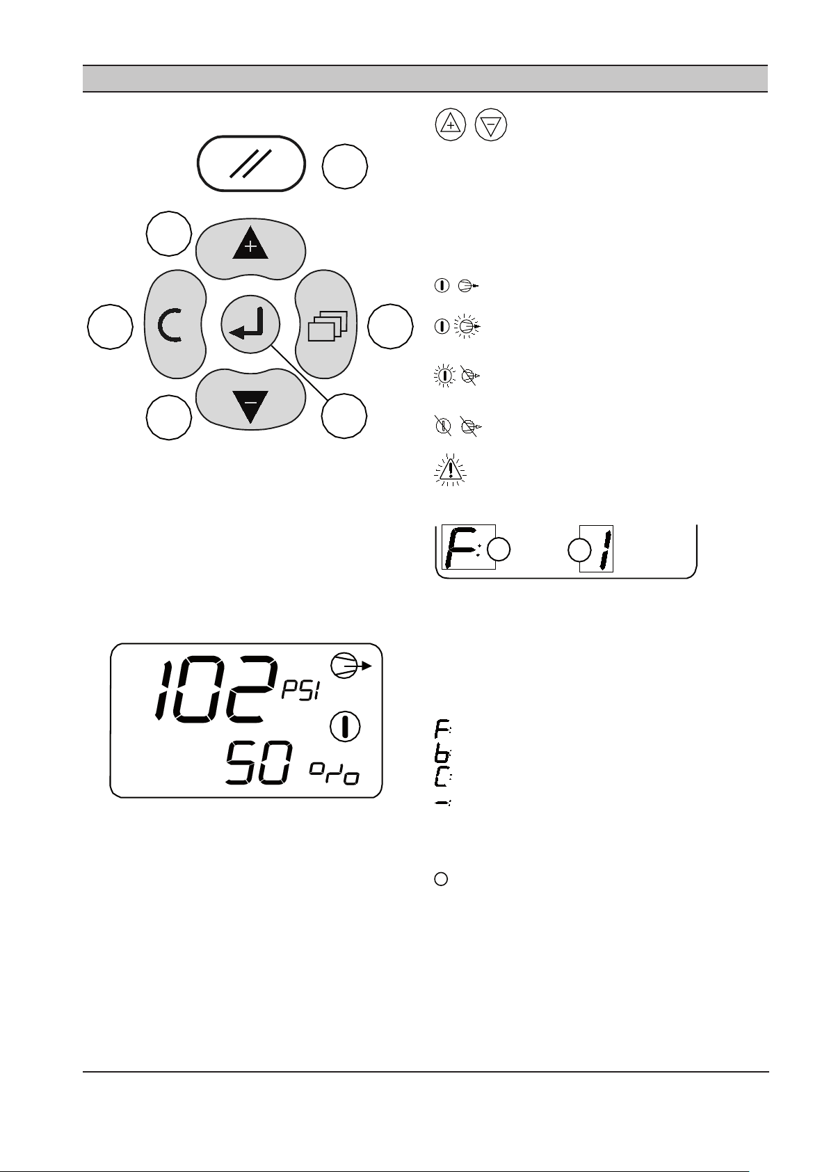
Toetsenblok:
a
f
e
d
c
b
A
B
i
Reset
a)
Menu
b)
Enter
c)
PARAGRAAF 7 WERKING VAN SCHERMEN EN MENU’S
Druk op Omhoog of Omlaag om andere
items van het gebruikersmenu te zien.
Het scherm blijft voor onbepaalde tijd op het
geselecteerde item van het ‘gebruikersmenu’.
Bij het opstarten of resetten gaat het scherm als
standaardinstelling terug naar het eerste item op het
menu.
Statussymbolen:
AAN/AAN In bedrijf
AAN/Knippert Handmatige modus
Knippert/UIT Geforceerd open/gesloten
UIT/UIT Uitgeschakeld door storing
Knippert Storing
Status:
Omlaag (Min)
d)
Omhoog (Plus)
e)
Escape (Annuleren)
f)
Scherm:
Druk = Hoofddrukweergave
% = Percentage klep open (0-100%)
De hoofddrukweergave hangt af van de bedrijfsmodus
of de instelling van de drukweergave in de Combinatie.
modus (1.dP). De hoofddrukweergave geeft de
drukwaarde als volgt weer:
Voorwaartse modus = Druk P4
Achterwaartse modus = Druk P3
Combinatiemodus = instelling menu 1.dP
Handmatige modus = instelling menu 1.dP
‘A’ = Actieve doeldrukinstelling
1, 2, 3 or 4 (1 = standaard)
Handmatige modus = “-“(streepje)
‘B’ = modus
Voorwaartse modus
Achterwaartse modus
Combinatiemodus
Handmatige modus
of geforceerd gesloten
of geforceerd open
zie ‘Statussymbolen’
ingersollrandproducts.com 11
Page 60

12 ingersollrandproducts.com
Druk op Omhoog of Omlaag om andere
items van het gebruikersmenu te zien.
P3 hoge druk, productiezijde, inlaat:
Alleen weergegeven in ‘voorwaartse’ modus als P3
sensor is aangebracht.
P4 lage druk, verbruikszijde, uitlaat:
Uitgang klepregeling (4-20 mA):
Bijvoorbeeld: 12.0 Ao = 12,0 mA, 50%
Netwerkadres (IRBUS-modus):
B01 = Nummer netwerk I/O Box
In de IRBUS-modus simuleert de IX Box een netwerk I/O
Box.
Bij netwerken die een I/O Box hebben, dient u ervoor
te zorgen dat het nummer van de I/O Box uniek is.
Wanneer het toestel geldige IRBUS-communicatie van
het XI beheerssysteem waarneemt, wordt het symbool
van de communicatie-indicator weergegeven:
Netwerkadres: Modbus-modus
Alleen weergegeven in ‘achterwaartse’ modus als P4
sensor is aangebracht.
‘Actieve hoge doeldruk’:
Volgens de actieve doeldruk H1, H2, H3 of H4
Niet weergegeven in voorwaartse of handmatige
modus.
‘Actieve lage doeldruk’:
Volgens de actieve doeldruk L1, L2, L3 of L4
Niet weergegeven in achterwaartse of handmatige
modus.
Modbusadres – decimaal getal 01 tot 99
Het symbool van de communicatie-indicator wordt
niet weergegeven in de Modbus-modus.
Page 61

PARAGRAAF 8 INBEDRIJFSTELLING
Bij het in werking stellen van de EX-Box, moet u de
volgende procedures uitvoeren voordat u probeert te
starten.
Aanbevolen wordt dat een erkende, gekwaliceerde
servicemonteur de X8I in gebruik stelt.
FYSIEKE CONTROLES
1. Voordat u de stroom aansluit op de IX Box, moet u er
zeker van zijn dat de voedingsaansluitingen juist zijn
en goed vastzitten (115 V AC of 230 V AC (+-10%),
50/60 Hz).
2. Open het voorpaneel van de IX Box en controleer
of alle druksensor-, RS485-, en andere aansluitingen
goed geïnstalleerd zijn en vastzitten.
Zie de paragraaf over Installatie voor meer
informatie.
3. Sluit het voorpaneel van de IX Box.
4. Schakel de stroomtovoer naar de IX Box aan.
5. De identicatie van het stuurprogramma wordt kort
getoond, gevolgd door het normaal bedrijfdisplay
voor de gebruiker.
DRUKSCHERM
Controleer de weergegeven persdruk. Als de druk
niet juist of onnauwkeurig is, controleert u het type
en bereik van de sensor en voert u de procedure voor
ingebruikstelling en kalibreren van de sensor uit.
3.3o Afwijking P4 uitlaatdruk
3.3r Bereik P4 uitlaatdruk
3.4o Afwijking P3 inlaatdruk
3.4r Bereik P3 inlaatdruk
1.3I P4 integrale tijd
De standaardwaarde is 10
Menu’s en Menu-items
Gebruikersconguratiemenu 1
INGESTELDE DRUKWAARDEN
Stel de doeldrukwaarde voor de voorwaartse modus
in volgens de systeemvereisten in het betreende
besturingsmenu:
2.L1 Lage doeldruk nr. 1
Menu’s en Menu-items
Doelconguratiemenu 2
OPTIONELE KENMERKEN EN FUNCTIES VAN
IX BOX
De installatievereisten kunnen de implementatie van
aanvullende of optionele functies en kenmerken met zich
meebrengen.
Als standaardinstelling zijn aanvullende optionele
functies en kenmerken gedeactiveerd of verhinderd.
Kenmerken en functies; menu-items
OPSTARTEN VAN IX INTELLIFLOW
1. Begin wanneer u voor het eerst opstart met de
omloop open.
2. Stel de waarden van de controller in op een
druk onderaan in de bestaande bovenstroomse
drukbandwijdte. Hierdoor ontstaat een
veranderingssysteem om de besturingsvariabelen
(proportionele druk en integrale tijd) handmatig af
te stellen en te controleren of de besturing stabiel is.
Zie de paragraaf De afstelparameters instellen
Menu’s en Menu-items
Sensorkalibratiemenu 3
BEDRIJFSMODUS
Stel de bedrijfsmodus voor de IX Box in het
desbetreende besturingsmenu in op de voorwaartse
modus:
1.oP Bedrijfsmodus
0: Voorwaartse modus
Dit is de standaardconguratie zoals deze vanuit
de fabriek wordt geleverd
Stel de afstelparameters voor de voorwaartse
besturingsmodus in met het desbetreende
besturingsmenu:
1.3P P4 proportionele druk
De standaardwaarde is 20
voor een beschrijving van de wijze waarop deze
waarden het besturingssysteem beïnvloeden.
3. Sluit de omloop langzaam.
4. Controleer het systeem en bevestig dat de
besturing stabiel is. Als er geen stabiele besturing
wordt bereikt, opent u de omloop, stelt u de
besturingsvariabelen bij en gaat u terug naar stap 3.
Ga anders verder naar stap 5.
5. Wanneer stabiele besturing is bereikt, verlaagt u de
ingestelde waarde geleidelijk totdat de optimale
waarde is bereikt.
BIJVOORBEELD:
Bestaande bovenstroomse druk: 6,9 tot 7,6 bar (100-110
psi) kritieke druk (minimaal): 5,8 bar (85 psi)
1. Begin met de omloopklep helemaal open.
2. Stel de controller in op 6,9 bar (100 psi).
ingersollrandproducts.com 13
Page 62

14 ingersollrandproducts.com
3. Sluit de omloopklep langzaam.
4. Als de besturing niet stabiel is (de klep overschrijdt
de juiste positie of de ingestelde waarde wordt
niet bereikt), moet u de omloop openen, de
besturingsvariabelen bijstellen en naar stap 3
teruggaan. Als de besturing stabiel is, gaat u verder
naar stap 5.
5. Verlaag de ingestelde waarde geleidelijk (en wacht
om te controleren of de besturing nog stabiel is)
totdat de optimale waarde is bereikt.
In dit voorbeeld kan de optionele ingestelde waarde
6,2 bar (90 psi) zijn, waarbij de benedenstroomse druk
wisselt tussen 6,1 bar (89,25 psi) en 6,25 bar (90,75 psi)
bij normaal bedrijf. Hierdoor ontstaat een veiligheid van
0,3 bar (5 psi) die voorkomt dat de benedenstroomse
druk onder 5,8 bar (85 psi) raakt bij een plotselinge
verandering van luchtverbruik of -toevoer.
DE AFSTELPARAMETERS INSTELLEN
1.3P P4 proportionele druk
De standaardwaarde is 20
1.3I P4 integrale tijd
De standaardwaarde is 10
PROPORTIONELE DRUK
Proportionele besturing varieert het signaal dat naar
de kleppen wordt gezonden als een lineaire reactie op
het verschil tussen de werkelijke systeemdruk en de
ingestelde systeemdruk. De gevoeligheid van de kleppen
kan worden bijgesteld via de IntelliFlow controller
met de ingestelde proportionele drukwaarde (1.3P.).
Deze schaalfactor is de hoeveelheid verandering in
de ingangsvariabele (werkelijke min ingestelde druk)
die een volledige verandering in de uitgangsvariabele
(kleppositie) veroorzaakt.
Met andere woorden, als de druk in het luchtsysteem
vaak wisselt, is het verstandig om de proportionele
druk op een lage waarde in te stellen (een waarde /
getal groter dan de fabrieksinstelling van 20) om deze
systeemveranderingen bij te kunnen houden. Als het
systeem daarentegen erg stabiel is, is het verstandig om
de proportionele druk op een hoge waarde in te stellen
(een waarde / getal lager dan de fabrieksinstelling van 20)
om deze systeemveranderingen bij te kunnen houden.
De proportionele druk heeft een rechtstreeks verband
met de gebruiksduur van de kleppen en een omgekeerd
verband met de klepcycli; dus naarmate de band kleiner
wordt, neemt de gebruiksduur van de kleppen af en
nemen de cyli toe.
Zoals eerder gezegd, de IntelliFlow controller gebruikt
een proportioneel plus integraal besturingsalgoritme. Het
resultaat van alleen proportionele besturing is afwijking
van de geregelde variabele uitlaatdruk. Dit betekent
dat als de ingestelde drukwaarde 100 is, de werkelijke
druk misschien maar 95 is. De waarde van deze afwijking
hangt af van de waarde van de proportionele druk.
Wat is de klepreactie als het verschil tussen de werkelijke
en ingestelde druk nul is? Er is geen reactie. Proportionele
besturing werkt alleen als er een verschil of een fout
is. Ontwerp-uitlaatdruk kan niet worden bereikt in een
alleen proportioneel besturingssysteem. Daarom is er
een integraal besturingssysteem aan toegevoegd om de
gewenste uitlaatdruk te verkrijgen.
INTEGRALE TIJD
De afwijking die ontstaat door het proportionele
besturingsalgoritme kan worden verwijderd door
de ingestelde systeemdruk handmatig bij te stellen.
Volgens het bovenstaande voorbeeld kan de waarde
worden ingesteld op 105 om de gewenste 100 te krijgen.
Het zou nodig zijn de waarde handmatig te verstellen
naarmate het systeemverbruik wisselde. Integrale
besturing, ook ‘reset control’ genoemd, stelt de gewenste
systeemdrukwaarde automatisch terug. Bij de IntelliFlow
controller wordt de frequentie waarmee de controller
de systeemdrukwaarde terugstelt integrale tijd, (1.3I.),
genoemd, deze wordt uitgedrukt in minuten tussen
resets.
Als precieze regeling van de opgegeven uitlaatdruk
nodig is, moet de integrale tijd op een snelle waarde
worden ingesteld. Met andere woorden, als de druk
in het luchtsysteem vaak wisselt, is het verstandig om
de integrale tijd op een hoge waarde in te stellen (een
waarde / getal groter dan de fabrieksinstelling van 10) om
deze systeemveranderingen bij te kunnen houden. Als
het systeem daarentegen erg stabiel is, is het verstandig
om de integrale tijd op een lage waarde in te stellen (een
waarde / getal lager dan de fabrieksinstelling van 10) om
deze systeemveranderingen bij te kunnen houden. Deze
tijd heeft een rechtstreeks verband met de gebruiksduur
van de kleppen en een omgekeerd verband met de
klepcycli, dus, naarmate de integrale tijd toeneemt,
neemt de gebruiksduur van de kleppen toe en nemen de
cycli af.
Wanneer de band laag is en de integrale tijd snel, is er
aanzienlijke klepactiviteit, wat betreft omvang zowel
als frequentie, om de gewenste ingestelde waarde te
verkrijgen. In het andere scenario, als de band hoog
is en de integrale tijd langzaam, is er relatief weinig
klepactiviteit, en is het mogelijk dat de ingestelde waarde
nooit wordt bereikt.
Proportionele druk en integrale tijd zijn variabelen die
intern door het besturingssysteem worden gebruikt
om de klepreactie en -richting te bepalen voor een
bepaald persluchtsysteem. Elk heeft een optimale waarde
gebaseerd op de kenmerken van het systeem. Deze
optimale waarden worden proefondervindelijk bepaald.
Deze ingestelde waarden moeten opnieuw worden
geëvalueerd telkens wanneer er een grote verandering in
het persluchtsysteem plaatsvindt.
Page 63

PARAGRAAF 9 SYSTEEMCONFIGURATIE
WERKING VAN SCHERM EN MENU’S
Alle mogelijkheden van waarden, parameters of opties
zijn in menulijsten gegroepeerd. De items worden aan
een lijst toegewezen op basis van type en classicatie.
Items die kunnen worden gebruikt om opties te
selecteren of functies aan te passen worden toegekend
aan de ‘menumoduslijsten’. Items die een gebruiker
mogelijk moet bekijken tijdens gewone werking,
bijvoorbeeld gedetecteerde druk, worden toegekend aan
de lijst van de normale werkingsmodus.
Elk menu heeft een unieke toegangscode. Er kan slechts
één menu tegelijk worden ingevoerd.
TOEGANG TOT DE IX
CONFIGURATIESCHERMEN
Om toegang tot een menu te krijgen, drukt u op
MENU.
Op het scherm ziet u vier ‘0’-tekens; het
eerste teken knippert.
Druk op Omhoog of Omlaag om het eerste
teken te veranderen in het eerste teken van de vereiste
toegangscode. Als het nummer van de toegangscode
minder is dan ‘1000’, is het eerste teken ‘0’. Druk op Enter
om het tweede teken van de code te verhogen.
code knippert, drukt u op Enter. Als de toegangscode
correct is voor toegang tot een van de toegankelijke
menu’s, verschijnt het eerste menu-item van het
betreende menu. Als de toegangscode onjuist is, keert
het scherm terug naar het normale bedrijfsscherm.
Om een menu-item te selecteren om het
aan te passen, drukt u op Omhoog of Omlaag totdat het
menu-item wordt weergegeven.
Om de instelling van een item aan te passen, drukt
u op Enter; de waarde of optie knippert.
Druk op Omhoog of Omlaag om bij te
stellen zoals nodig.
Druk op Enter om de waarde in het geheugen op te
slaan.
Om de menuroutine af te sluiten en naar het
normale bedrijfsscherm terug te gaan, kunt u op
ieder moment op Annuleren drukken. Het normale
bedrijfsscherm keert terug. Iedere wijziging die niet in het
geheugen is ingevoerd, wordt geannuleerd en de vorige
instelling blijft behouden.
De menucodes staan naast elk menu. Zie
Overzicht van het conguratiemenu voor de codes
Wanneer alle vier tekens van de
toegangscode zijn ingesteld, en het laatste teken van de
ingersollrandproducts.com 15
Page 64

16 ingersollrandproducts.com
OVERZICHT VAN HET CONFIGURATIEMENU
1. - -
2. - -
3. - -
4. - -
5. - -
Elk menu is afzonderlijk toegankelijk via de volgende
toegangscodes.
Gebruikersconguratiemenu 1
Toegangscode menu ‘0011’
1.oP Bedrijfsmodus
1.3P P4 proportionele druk
1.3I P4 integrale tijd
1.4P P3 proportionele druk
1.4I P3 integrale tijd
1.bA Algoritme achterwaartse modus
1.Po Handmatige modus % open
1.SP Maximaal % verandering/seconde
1.LP Klep % open laag niveau
1.HP Klep % open hoog niveau
1.SF Reactie op stuurdrukstoring
1.CF Reactie op communicatiestoring
1.Ad Netwerkadres
1.Pd Drukweergave-eenheid
1.dP Drukweergave. in combinatiemodus
Doelconguratiemenu 2
Toegangscode menu ‘0021’
2.L1 Lage doeldruk nr. 1 (standaard)
2.H1 Hoge doeldruk nr. 1 (standaard)
2.L2 Lage doeldruk nr. 2
2.H2 Hoge doeldruk nr. 2
2.L3 Lage doeldruk nr. 3
2.H3 Hoge doeldruk nr. 3
2.L4 Lage doeldruk nr. 4
2.H4 Hoge doeldruk nr. 4
Relaisfuncties R1 tot R6
Toegangscode menu ‘0041’ (R1) tot ‘0046’ (R6)
4.F1 Ingangsfunctie nr. 1 (A, b en C)
4.F2 Ingangsfunctie nr. 2 (A, b en C)
4.Fu Logicafunctie
4.on Vertragingstijd Aan
4.oF Vertragingstijd Uit
4.St Normale staat
4.CF Reactie op storing RS485
Diagnostisch menu 5
Toegangscode menu ‘0051’
5.d1 Digitale ingang nr. 1 (Di 1)
5.d2 Digitale ingang nr. 2 (Di 2)
5.d3 Digitale ingang nr. 3 (Di 3)
5.d4 Digitale ingang nr. 4 (Di 4)
5.d5 Digitale ingang nr. 5 (Di 5)
5.d6 Digitale ingang nr. 6 (Di 6)
5.r1 Uitgangsrelais nr. 1 (R1)
5.r2 Uitgangsrelais nr. 2 (R2)
5.A1 Analoge ingang nr. 1 (Ai1)
5.A2 Analoge ingang nr. 2 (Ai2)
5.Ao Analoge uitgang (Ao)
Sensorkalibratiemenu 3
Toegangscode menu ‘0031’
3.3o Afwijking P4 uitlaatdruk
3.3r Bereik P4 uitlaatdruk
3.4o Afwijking P3 inlaatdruk
3.4r Bereik P3 inlaatdruk
Page 65

GEBRUIKERSCONFIGURATIEMENU 1
1.oP – Bedrijfsmodus
Er zijn 5 bedrijfsmodi voor de IX IntelliFlow controller.
0: Voorwaartse modus
P4 druksensor (uitlaat, lage druk, verbruikszijde) wordt
gebruikt voor de stuurdruk volgens de ingestelde
waarde van de actieve ‘lage doeldruk’ (2.L1 tot 2.L4).
De ingestelde waarden voor ‘hoge doeldruk’ (2.H1 tot
2.H4) zijn verhinderd en eventuele storingen van de P3
druksensor worden genegeerd.
De klep regelt met behulp van de P4 druk volgens
de instellingen van ‘1.4P’ proportionele druk en ‘1.4I’
integrale tijd.
De actie van de voorwaartse besturingsmodus is:
Doelwaarde is 6,55 bar (95 psi)
Als P3 boven 6,55 bar (95 psi) blijft:
P4 blijft op de doelwaarde van P4:
Als het verbruik toeneemt en P4 onder 6,55 bar (95 psi)
daalt:
De klep gaat open tot 100%
Als het verbruik afneemt en P4 boven 6,55 bar (95 psi)
stijgt:
De klep sluit tot 0%
Als P3 onder 6,55 bar (95 psi) daalt:
De klep gaat 100% open en druk P4 is gelijk aan
druk P3
Deze bedrijfsmodus is bedoeld om een constante druk aan
de verbruiks- of uitlaatzijde te handhaven terwijl de druk
aan de productie- of inlaatzijde op een hoger niveau is.
1: Achterwaartse modus
P3 druksensor (inlaat, hoge druk, productiezijde) wordt
gebruikt voor de stuurdruk volgens de ingestelde
waarde van de actieve ‘hoge doeldruk’ (2.H1 tot 2.H4). De
ingestelde waarden voor ‘lage doeldruk’ (2.L1 tot 2.L4) zijn
verhinderd en eventuele storingen van de P4 druksensor
worden genegeerd.
If ‘1.bA = 0’:
De algoritmeparameters ‘1.4P’ (P4 proportionele druk) en
‘1.4I’ (P4 integrale tijd) worden gebruikt.
If ‘1.bA = 1’:
De algoritmeparameters ‘1.3P’ (P3 proportionele druk) en
‘1.3I’ (P3 integrale tijd) worden gebruikt.
De klep reguleert met behulp van de druksensor
P3 (inlaat, hoge druk, productiezijde) volgens de
toepasselijke instellingen voor ‘proportionele’ druk en
‘integrale’ tijd.
De actie van de achterwaartse besturingsmodus is:
Doelwaarde is 5,51 bar (80 psi)
Als P3 tot 5,51 bar (80 psi) daalt:
P3 kan niet onder 80 psi dalen:
Als P3 onder 5,51 bar (80 psi) daalt:
De klep sluit tot 0%
Als P3 boven 5,51 bar (80 psi) stijgt:
De klep gaat tot 100% open en druk P4 is gelijk
aan druk P3.
Deze bedrijfsmodus is bedoeld om te verzekeren dat
een minimale opgegeven druk aan de productie- of
inlaatzijde gehandhaafd blijft in gevallen waar het
luchtverbruik aan de verbruiks-, of uitlaatzijde, overmatig
hoog wordt en de druk aan de verbruikszijde begint te
dalen.
2: Combinatiemodus
Zowel de P4 druksensoren (uitlaat, lage druk,
verbruikszijde) als de P3 druksensoren (inlaat, hoge
druk, productiezijde) worden gebruikt voor besturing.
De besturingsalgoritmen van de ‘voorwaartse’ modus en
de ‘achterwaartse’ modus werken tegelijkertijd samen.
Het besturingsalgoritme dat de laagste waarde voor %
open produceert krijgt prioriteit; de klep volgt de laagste
waarde voor % open.
In de combinatiemodus hangen de werking en het
gebruik van de klep af van de verhouding tussen
de ingestelde waarden van ‘lage doeldruk’ en ‘hoge
doeldruk’.
De actie van de achterwaartse besturingsmodus is:
Doelwaarde P4 is 6,55 bar (95 psi)
Doelwaarde P3 is 5,51 bar (80 psi)
Als P3 boven 6,55 bar (95 psi) blijft:
P4 blijft op de doelwaarde van P4:
Als het verbruik toeneemt en P4 onder 6,55 bar (95 psi)
daalt
De klep gaat open tot 100%
Als het verbruik afneemt en P4 boven 6,55 bar (95 psi)
stijgt:
De klep sluit tot 0%
Als P3 onder 6,55 bar (95 psi) daalt maar boven 5,51 bar
(80 psi) blijft:
De klep gaat 100% open en druk P4 is gelijk aan
druk P3.
Als P3 tot 5,51 bar (80 psi) daalt
P3 kan niet onder 5,51 bar (80 psi) dalen:
Als P3 onder 5,51 bar (80 psi) daalt:
De klep sluit tot 0%
Als P3 boven 5,51 bar (80 psi) stijgt:
De klep gaat open tot 100%
Als P3 boven 5,51 bar (80 psi) blijft:
De klep blijft geheel open en druk P4 wordt
gelijk aan druk P3.
ingersollrandproducts.com 17
Page 66

18 ingersollrandproducts.com
3: Handmatige modus
De klep gaat open tot de waarde van percentage
open die is opgegeven in ‘1.Po’. De klep blijft vast op
deze waarde van % open, ongeacht de ingestelde
doeldrukwaarden, variatie in gedetecteerde druk,
beschikbaarheid van druksensoren of storingsconditie
van sensoren.
4: Geforceerd gesloten
De klep wordt geforceerd ‘gesloten’. Storingen van P3
P4 druksensoren worden genegeerd. Wanneer ‘gesloten
forceren’ geactiveerd is, sluit de klep onmiddellijk volgens
de ingestelde limiet ‘1.SP’ percentage verandering per
seconde. De instelling ‘1.SP’ beperkt hoe snel de klep sluit.
5: Geforceerd open
De klep wordt geforceerd ‘geopend’. Storingen van P3
P4 druksensoren worden genegeerd. Wanneer ‘open
forceren’ geactiveerd is, opent de klep onmiddellijk
volgens de ingestelde limiet ‘1.SP’ percentage
verandering per seconde. De instelling ‘1.SP’ beperkt hoe
snel de klep opent.
1.3P P3 proportionele drukfactor
Het drukbereik, boven en onder de ingestelde ‘doeldruk’,
waar integrale besturing optreedt.
1.3I P3 integrale tijdsfactor
De tijd waarin de uitgang een volledige verandering van
4 mA tot 20 mA, 0-100% (of omgekeerd) zal uitvoeren.
1.4P P4 proportionele drukfactor
Het drukbereik, boven en onder de ingestelde ‘doeldruk’,
waar integrale besturing optreedt.
1.4I P4 integrale tijdsfactor
De tijd waarin de uitgang een volledige verandering van
4 mA tot 20 mA, 0-100% (of omgekeerd) zal uitvoeren.
1.bA Algoritme achterwaartse modus
0 - De algoritmeparameters ‘1.4P’ (P4 proportionele
druk) en ‘1.4I’ (P4 integrale tijd) worden gebruikt
voor bedrijf in de ‘achterwaartse’ modus.
1 - De algoritmeparameters ‘1.3P’ (P3 proportionele
druk) en ‘1.3I’ (P3 integrale tijd) worden
gebruikt voor bedrijf in de ‘achterwaartse’
modus. (standaardinstelling).
1.Po Handmatige modus waarde % open
Handmatige modus waarde % open (0 tot 100%)
zie ‘Handmatige modus’ (1.oP)
1.SP % verandering/seconde
Beperkt hoe snel de klep opent of sluit wanneer de
druk plotseling verandert en/of de ‘doeldruk’ aanzienlijk
wordt veranderd. Als het toepasselijke of overheersende
doelalgoritme een verandering in % open veroorzaakt die
groter is dan de instelling ‘1.SP’, is de verandering in klep
% open beperkt tot het maximale % verandering bepaald
door de instelling ‘1.SP’ totdat de vereiste stand van %
open van de klep is bereikt.
De instelling ‘1.SP’ wordt uitgedrukt in % verandering
per seconde waarbij een instelling van 20% iedere
verandering beperkt tot een maximum van 20% open
per seconde - de klep verandert van geheel open (100%
open) tot geheel gesloten (0% open) in vijf seconden als
de vereiste waarde van % open plotseling verandert van
100% open in 0% open.
‘1.SP’ is altijd actief in alle modi.
1.LP Klep % open laag niveau
Als klep % open < ingestelde waarde ‘1.LP’; dan is de staat
Ai#3 ‘S’ ingesteld op ‘1’. Ai#3 ‘S’ staat gaat terug tot ‘0’ als
klep % open >= ‘1.LP’.
Deze instelling heeft geen eect op de werking van de
klep of de % open stand maar kan worden gebruikt bij
lokale en/of systeembrede ‘virtueel relais’ automatisering.
1.HP Klep % open hoog niveau
Als klep % open > ingestelde waarde ‘1.HP’; dan is de
staat Ai#4 ‘S’ ingesteld op ‘1’. Ai#4 ‘S’ staat gaat terug tot ‘0’
als klep % open <= ‘1.HP’.
Deze instelling heeft geen eect op de werking van de
klep of de % open stand maar kan worden gebruikt bij
lokale en/of systeembrede ‘virtueel relais’ automatisering.
1.SF Reactie op stuurdrukstoring
Als een storing in de ‘stuurdruk’ of een druksensor in de
combinatiemodus optreedt:
0 - Handmatige modus
1 - Klep open forceren (standaardinstelling)
2 - Klep gesloten forceren
1.CF Reactie op communicatiestoring
Als een storing in de netwerkcommunicatie optreedt:
0 – Normaal doorgaan (standaardinstelling)
1 – Klep open forceren
2 – Klep gesloten forceren
Alleen van toepassing in IRBUS communicatiemodus;
altijd ‘0’ (normaal doorgaan) in Modbus-modus.
1.Ad Netwerkadres
Modbus:
01 tot 99 decimaal (0 tot 63 Hex)
IRBUS-modus:
b01 tot b12 (I/O Box 1 tot 12)
IRBUS- of Modbus-modus wordt automatisch
geselecteerd afhankelijk van het ingestelde adres.
1.Pd Drukweergave-eenheden
0 – bar
1 - psi (standaardinstelling)
1.dP Drukweergave. in combinatiemodus
Bepaalt of de P3 of P4 druk wordt weergegeven
als de ‘hoofddrukweergave’ tijdens bedrijf in de
combinatiemodus.
0 – P4 (standaardinstelling)
1 – P3
Page 67

DOELDRUKMENU 2
2.L1 Lage doeldruk nr. 1 (standaard)
Normale standaarddruk aan de uitlaatzijde wanneer geen
digitale ingangen geactiveerd zijn.
Actief in ‘voorwaartse’ en ‘combinatiemodus’; niet
gebruikt voor ‘achterwaartse’ modus.
2.H1 Hoge doeldruk nr. 1 (standaard)
Normale standaarddruk aan de inlaatzijde wanneer geen
digitale ingangen geactiveerd zijn.
Actief in ‘achterwaartse’ en ‘combinatiemodus’; niet
gebruikt voor ‘voorwaartse’ modus.
2.L2 Lage doeldruk nr. 2
Van toepassing wanneer digitale ingang
‘doeldrukinstelling 2’ geactiveerd is.
Actief in ‘voorwaartse’ en ‘combinatiemodus’; niet
gebruikt voor ‘achterwaartse’ modus.
2.H2 Hoge doeldruk nr. 2
Van toepassing wanneer digitale ingang
‘doeldrukinstelling 2’ geactiveerd is.
Actief in ‘achterwaartse’ en ‘combinatiemodus’; niet
gebruikt voor ‘voorwaartse’ modus.
2.L3 Lage doeldruk nr. 3
Van toepassing wanneer digitale ingang
‘doeldrukinstelling 3’ geactiveerd is.
Actief in ‘voorwaartse’ en ‘combinatiemodus’; niet
gebruikt voor ‘achterwaartse’ modus.
2.H3 Hoge doeldruk nr. 3
Van toepassing wanneer digitale ingang
‘doeldrukinstelling 3’ geactiveerd is.
Actief in ‘achterwaartse’ en ‘combinatiemodus’; niet
gebruikt voor ‘voorwaartse’ modus.
2.L4 Lage doeldruk nr. 4
Van toepassing wanneer digitale ingang
‘doeldrukinstelling 4’ geactiveerd is.
Actief in ‘voorwaartse’ en ‘combinatiemodus’; niet
gebruikt voor ‘achterwaartse’ modus.
2.H4 Hoge doeldruk nr. 4
Van toepassing wanneer digitale ingang
‘doeldrukinstelling 4’ geactiveerd is.
Actief in ‘achterwaartse’ en ‘combinatiemodus’; niet
gebruikt voor ‘voorwaartse’ modus.
Als meer dan één digitale ingang geactiveerd is, geldt
de volgende prioriteit:
1: (hoogste prioriteit) Gesloten forceren
2: Open forceren
3: Handmatige modus
4: Doelinstelling nr. 2
5: Doelinstelling nr. 3
6: (laagste prioriteit) Doelinstelling nr. 4
SENSORKALIBRATIEMENU 3
3.3o Afwijking P3 druksensor
3.3r Bereik P3 druksensor
Kalibratie-instellingen P3 druksensor (inlaat, hoge druk,
productiezijde).
zie ‘Kalibratieprocedure druksensor’
3.4o Afwijking P4 druksensor
3.4r Bereik P4 druksensor
Kalibratie-instellingen P4 druksensor (uitlaat, lage druk,
verbruikszijde).
zie ‘Kalibratieprocedure druksensor’
Kalibratieprocedure druksensor:
1) Inbedrijfstelling
Stel eerst ‘Afwijking’ (minimum) in op de minimale
of laagste drukwaarde voor de sensor. Stel ‘Bereik’
(maximum) in op de maximale of hoogste waarde
voor de sensor.
Bijvoorbeeld:
Als de druksensor van het type 0 tot 16,0 bar (0 tot
232 psi) is, stelt u de ‘afwijking’ in op 0 bar (0 psi) en
het ‘bereik’ op 16,0 bar (232 psi).
Voer de kalibratieprocedure uit.
2) Kalibratieprocedure
a) Afwijking: Stel de sensor bloot aan de atmosfeer en
stel de instelling voor ‘afwijking’ (indien nodig) bij
tot de gedetecteerde drukweergave 0 bar (0 psi)
bedraagt.
b) Bereik: Oefen een nauwkeurig bekende druk
uit op de druksensor en stel de instelling van
‘bereik’ bij totdat de gedetecteerde drukweergave
overeenkomt met de uitgeoefende druk. Een
opgezette druk gelijk aan of groter dan de nominale
systeemwerkdruk is aanbevolen.
De gedetecteerde druk wordt weergegeven met
het kalibratiemenu-item en zal wijzigen om overeen
te komen met de nieuwe kalibratie-instelling
wanneer de instelling wordt aangepast.
De toegepaste druk hoeft niet statisch te zijn.
Hij kan dynamisch zijn en wijzigen. Hierdoor kan
de kalibratie worden uitgevoerd op een volledig
operationeel systeem waarbij de veranderlijke
systeemdruk nauwkeurig kan worden gecontroleerd
vanaf een andere bron.
De druksensor correct instellen en kalibreren is
essentieel voor een geslaagde systeemwerking.
Het wordt aanbevolen dat de druksensorijking
jaarlijks of vooraf bepaald op periodieke basis wordt
onderzocht en indien nodig wordt aangepast.
RELAISCONFIGURATIEMENU 4
zie ‘Automatisering met virtuele relais
ingersollrandproducts.com 19
Page 68

20 ingersollrandproducts.com
PARAGRAAF 10 DIAGNOSE
D1 Digitale ingang 1
D2 Digitale ingang 2
D3 Digitale ingang 3
D4 Digitale ingang 4
D5 Digitale ingang 5
D6 Digitale ingang 6
-------------------------------------------------------------
R1 Relaisuitgang 1
R2 Relaisuitgang 2
-------------------------------------------------------------
A1 Analoge ingang 1 psi <> mA
A2 Analoge ingang 2 psi <> mA
1: AAN
0: UIT
ANN
UIT
------------------------------------------------------------Ao Analoge uitgang 0.0 to 20.0mA
DIAGNOSTISCH MENU 5
De IX IntelliFlow controller is voorzien van uitgebreide
diagnosefuncties. Elke ingang kan afzonderlijk worden
onderzocht en elke uitgang kan handmatig geactiveerd
of afzonderlijk gemanipuleerd worden.
Controllerdiagnose P2:
Alle instellingen op de standaardwaarden terugzetten:
Voer een toegangscode van ‘9750’ in; druk niet op Enter
wanneer het laatste teken knippert.
Houd ANNULEREN 10 seconden ingedrukt; de controller
wordt gereset en alle instellingen gaan terug naar
de standaardwaarden. Alle eerdere instellingen zijn
permanent verloren.
Relaisuitgangen:
De spanning van elke relaisuitgang kan handmatig
worden aan- en uitgezet door dit item te selecteren.
Gebuik Omhoog (plus) en Omlaag (min) om in te stellen
en druk op Enter.
Analoge ingangen:
Dit item wisselt de gedetecteerde waarde en de
elektrische meting op de aansluitklemmen van de ingang
van de controller af. Met een onafhankelijk meetapparaat
kunt u de weergegeven elektrische meetwaarde
controleren.
A1: P4 uitlaatdruk, 4-20 mA
A2: P3 inlaatdruk, 4-20mA
Analoge uitgang:
De analoge uitgang kan handmatig op ieder gewenst
niveau worden afgesteld. Druk op Enter en gebruik dan
Omhoog (Plus) en Omlaag (Min) om af te stellen en druk
op Enter. De uitgang neemt de normale bedrijfswaarde
weer aan als u het menu verlaat.
Page 69
PARAGRAAF 11 STORINGSCODES
Bij een storing van de IX IntelliFlow IX Box geeft de IX
Box een storingscode weer. De storingscode wordt een
item in het gebruikersmenu van het bedrijfsscherm. Als
er meer dan één actieve storing optreedt, worden ze
elk als een afzonderlijk item in het gebruikersmenu van
het bedrijfsscherm weergegeven; druk op Omhoog of
Omlaag om alle actieve storingscodes te zien of om het
normale statusscherm te zien.
Storingscodes worden verdeeld in A: Alarm
(waarschuwing) en E: Storing/uitschakeling.
Storingen in druksensoren:
De reactie op een storing in een druksensor hangt af van
de sensor en modus. Als de druksensor wordt gebruikt
voor ‘stuurdruk’, of als het toestel in de ‘combinatiemodus’
is, wordt de controller uitgeschakeld.
Als de sensor niet wordt gebruikt voor ‘stuurdruk’ en
het toestel niet in de ‘combinatiemodus’ is, wordt de
sensorstoring genegeerd en geeft de bijbehorende
drukweergave “- - - -“ (streepjes) weer.
Storingscodes:
E0115 Storing P4 druksensor
E0125 Storing P3 druksensor
Weergave van storingscode van XI beheerssysteem op
afstand:
Wanneer het XI beheerssysteem is ingesteld voor een I/O
Box-adres (b01 tot b12), kan het worden ingesteld om het
toestel te bewaken op storingstoestanden.
B’nn’57 ‘nn’ = nummer IO Box (01 tot 12)
Storing P4 druksensor aan verbruikszijde bij bedrijf in
voorwaartse of combinatiemodus.
B’nn’58 ‘nn’ = nummer IO Box (01 tot 12)
Storing P3 druksensor aan productiezijde bij bedrijf in
achterwaartse of combinatiemodus.
B’nn’60 ‘nn’ = nummer IO Box (01 tot 12)
Algemene storing (uitschakeling)
B’nn’ - - ‘nn’ = nummer IO Box (01 tot 12)
Verstoring of verlies van RS485-communicatie.
Wanneer het toestel in de IR485-modus is
en is aangesloten op een netwerk, kunnen de ‘B’
storingscodes worden bewaakt en weergegeven door
een XI systeembeheereenheid. De ‘B’ codes worden niet
weergegeven op het scherm van de IntelliFlow.
E0821 Kortsluiting
Kortsluiting gedetecteerd op de hoofdcontroller (digitale
ingangen)
E0866 DC-voeding laag
Controleer de spanning van de hoofdvoeding.
E5000 Mapfout intern geheugen
De controller van het toestel heeft verstoring van het
interne werkgeheugen (RAM) gedetecteerd. De integriteit
van de inhoud van het RAM-geheugen is verdacht; de
controller moet gereset worden om het geheugen te
wissen en opnieuw in te delen. Vernieuw de controller als
deze storingstoestand aanhoudt.
De hoofdstroomvoorziening van de besturing moet
worden verwijderd en opnieuw worden geïnstalleerd om
deze conditie te resetten.
ingersollrandproducts.com 21
Page 70

22 ingersollrandproducts.com
PARAGRAAF 12 ONDERDELENLIJST VAN IX INTELLIFLOW CONTROLLER
3
20mm
5mm
IEC
1
253
160
90
2
A
B
205
253
4242
160 136
24
IX Box
Item Onderdeelnr. Omschrijving
- 23451966 IX IntelliFlow
1 23451974 Unit, IX IntelliFlow
2 634067 Gland, Set - Pg13.5
- 80445588 Manual, User CD
ACCESSOIRES:
Nodig voor P3 en P4 systeemdrukomvomers
Item Onderdeelnr. Omschrijving
3 634065 Druksensor – Aantal (2)
4-20mA, 0-232 psi (0-16.0bar)
Item Onderdeelnr. Omschrijving
2 634104 IEC zekering T1.6A
PARAGRAAF 13 TECHNISCHE GEGEVENS VAN IX INTELLIFLOW
CONTROLLER
Technische gegevens IX Box
Afmetingen 10” x 6.3” x 3.6”
Gewicht 5.0lb (2.2kg)
Bevestiging muur, 2 schroeven (8 mm)
Behuizing IP54, NEMA 12
Voeding 100 to 240Vac +/- 10%
Vermogen 100VA
Temperatuur 32°F to 115°F (0°C to 46°C)
Vochtigheidsgraad 95% RV niet-condenserend
Montageafmetingen (mm):
253 x 160 x 90mm
Page 71
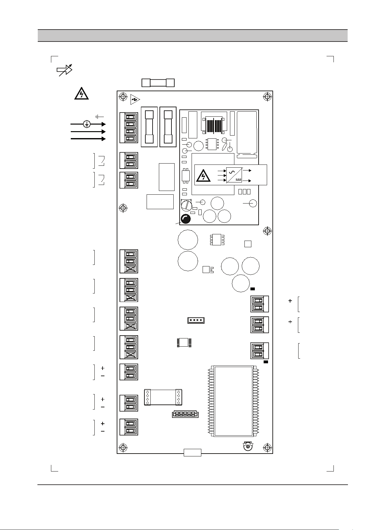
FH1
T1
.6
A
FH2
X10
T1
.6
A
PSU
IEC
20 x 5mm
LED1b
N
L
E
0VDC
+VDC
X09
X08
RL1
RL2
C01
Ai2
ACM
C018
RT1
X07
X06
X05
X04
X03
X02
X01
LCD
Ai2
C
Ai1
+C
Ao
A-GND
R1
R2
1
2
1
2
1
2
3
1
2
1
2
1
2
Di5
+C
Di6
D6
+C
+L1 (A)
RS
48
5
-L2 (B)
D5
2
1
2
1
2
1
4-20mA
4-20mA
4-20mA
Di4
GND
D4
+24 VDC
IR IntelliFlow Valv e
Control Unit - P2
100-240Vac
60VA
50/60Hz
1
2
3
4
E
L
N
X11
X12
X13
P2
4-20mA
LED2
LED1
+C
1
2
3
Di3
GND
D3
+24 VDC
+C
1
2
3
Di2
GND
D2
+24 VDC
+C
1
2
3
Di1
GND
D1
+24 VDC
+C
PARAGRAAF 14 IX INTELLIFLOW CONTROLLER BEDRADINGSSCHEMA
ingersollrandproducts.com 23
Page 72

24 ingersollrandproducts.com
4-20mA
100m (330ft) max
1
2
3
1
2
3
1
2
3
1
2
3
1
2
Ai2
+C
2
1
1
2
+L1
2
1
0VDC
+24VDC
D1
+L1 (A)
RS485
-L2 (B)
+L1 (A)
-L2 (B)
-L2
RS485
X13
X02
X04
X05
X06
X07
Di1
+C
0VDC
+24VDC
D2
0VDC
+24VDC
D3
0VDC
+24VDC
D4
+24VDC
Ai2
4-20mA
100m (330ft) max
1
2
Ai1
+C
2
1
X01
+24VDC
Ai1
P4
P3
Target 2
Target 3
Target 4
Outlet
Demand Side
Inlet
Supply Side
330ft (100m) max
IR IntelliFlow Valve
Control Unit - P2
GND
Pressure
Pressure
Modbus
P2
L NE
X10
1 2 3 4
4-20mA
100m (330ft) max
1
2
A-GND
Ao
2
1
X03
Ao
A-GND
IntelliFlow Valve
4-20mA Output
Ao
100-240Vac
100VA
50/60Hz
Virtual Relay
Configurable
240V 'CE ' / 115V 'UL ' @ 4A
maximum.
1
2
1
2
R1
R2
X09
X08
Di6
+C
Di5
+C
1
2
1
2
+24VDC
D5
+24VDC
D6
X12
X11
Force Closed
Force Open
Manual Mode
X02 X01
X03
P4
P3
Ao
Di2
+C
GND
Di3
+C
GND
Di4
+C
GND
330ft (100m) max
330ft (100m) max
330ft (100m) max
330ft (100m) max
330ft (100m) max
Page 73

MONTAGE BEHUIZING
A B
A
B
1
2
Gebruik een Torx schroevendraaier van de juiste
maat
Bij overmatige plaatselijke belasting of kracht kan de
behuizing breken:
1. Gebruik altijd de bijgeleverde sluitringen.
2. Draai de bevestigingsmiddelen niet te strak aan.
Zie ‘Technische gegevens’ voor de afmetingen van de
behuizing en de montageafmetingen.
ingersollrandproducts.com 25
Kabelinstallatie en draadaansluitingen:
Keer het voorpaneel om en zet het vast aan de
bevestigingsmiddelen van het onderste voorpaneel aan
de achterkant van de behuizing.
Page 74

26 ingersollrandproducts.com
PARAGRAAF 15 AFSTANDSBEDIENING VAN IX INTELLIFLOW CONTROLLER
1
2
3
1
2
3
1
2
3
1
2
3
0VDC
+24VDC
D1
X04
X05
X06
X07
Di1
+C
0VDC
+24VDC
D2
0VDC
+24VDC
D3
0VDC
+24VDC
D4
T2
T3
T4
GND
M
Di2
+C
GND
Di3
+C
GND
Di4
+C
GND
Di6
+C
Di5
+C
1
2
1
2
+24VDC
D5
+24VDC
D6
X12
X11
FC
FO
330ft (100m) max
Virtual Relay
'CE' 240V @ 4A
'UL' 115V @ 4A
1
2
1
2
R1
R2
X09
X08
1
2
R1
X08
1
2
3
0VDC
+24VDC
D4
X07
M
INGANGSFUNCTIES VAN IX BOX
‘Spanningsvrij’ schakelcontact op afstand:
Gebruik kabelgeleiders van minimaal 20 gauge (0,5 mm2
CSA), niet langer dan 100 m (330 ft).
T2: Ingestelde waarden voor doeldruk nr. 2
T3: Ingestelde waarden voor doeldruk nr. 3
T4: Ingestelde waarden voor doeldruk nr. 4
M: Handmatige modus
FO: Open forceren
FC: Gesloten forceren
Ingangen op afstand zijn bedoeld voor activering
op afstand via een ‘spanningsvrij’ schakelcontact,
relaiscontact, PLC of andere afstandsbediening.
T2, T3 en T4:
Wanneer geen digitale ingangen ‘doeldrukinstelling’
(Di1 tot Di3) geactiveerd zijn, gebruikt de controller
‘doeldrukinstelling nr. 1’.
AUTOMATISERING MET VIRTUELE RELAIS
De ingangen voor doeldrukinstelling (2, 3 of 4),
handmatige modus of selectie van gesloten/open
forceren kunnen ook geactiveerd worden door de
IntelliFlow automatiseringsfuncties met ‘virtuele relais’
door de juiste ‘virtueel relais’ uitgang (R1 of R2) aan te
sluiten op de vereiste digitale ingang.
Bijvoorbeeld:
Virtueel relais uitgang R1 (X08) activeert de handmatige
modus (X07).
Combinaties van logica waarbij uitgangen via
automatisering met ‘virtuele relais’ en ‘spanningsvrije’
schakelcontacten op afstand of andere externe
apparaten te pas komen, kunnen via deze methodologie
geïmplementeerd worden.
Prioriteit ingangen op afstand:
Als meer dan één digitale ingang tegelijkertijd
geactiveerd is, geldt de volgende prioriteit:
1 (hoogste prioriteit): Gesloten forceren
2: Open forceren
3: Handmatige modus
4: Doelinstelling nr. 2
5: Doelinstelling nr. 3
6: (laagste prioriteit): Doelinstelling nr. 4
Bijvoorbeeld:
Als de ingangen ‘Open forceren’ en ‘Doelinstelling nr. 3’
beide geactiveerd zijn, reageert het toestel op de ingang
‘Open forceren’.
Page 75

PARAGRAAF 16 RS485 MODBUSREGISTERS VAN IX INTELLIFLOW
CONTROLLER
Modbus RTU-protocol op 9600, N-8-1
Registers 400XX:
‘XX’ Item, omschrijving
01 Status (R)
Bits:
0 - Voorwaartse modus
1 - Achterwaartse modus
2 - Combinatiemodus
3 - Handmatige modus
4 - Geforceerd gesloten
5 - Geforceerd open
6 - Storing regelsensor
7 - Uitschakeling algemene storing
(m.i.v. storing regelsensor)
02 P4 uitlaatdruk, psi (R)
03 P3 inlaatdruk, psi (R)
04 Klep % open x 100
0 tot 10000 = 0 tot 100% (R)
05 Ao - mA x 100
400 tot 2000 = 4,0 tot 20,0 mA (R)
06 Modus (R/W)
0 - Voorwaartse modus
1 - Achterwaartse modus
2 - Combinatiemodus
3 - Handmatige modus
4 - Gesloten forceren
5 - Open forceren
07 Lage doelwaarde nr. 1, psi (R/W)
08 Hoge doelwaarde nr. 1, psi (R/W)
09 Lage doelwaarde nr. 2, psi (R/W)
10 Hoge doelwaarde nr. 2, psi (R/W)
11 Lage doelwaarde nr. 3, psi (R/W)
12 Hoge doelwaarde nr. 3, psi (R/W)
13 Lage doelwaarde nr. 4, psi (R/W)
14 Hoge doelwaarde nr. 4, psi (R/W)
15 3P – P4 proportionele druk
mBar; 69mBar = 1psi (R/W)
16 3I – P4 integrale tijd; sec. (R/W)
17 4P – P3 proportionele druk (R/W)
mBar; 69mBar = 1psi (R/W)
18 4I – P3 integrale tijd; sec. (R/W)
19 BA – Algoritme achterwaartse modus (0=3P/3I;
1=4P/4I) (R/W)
20 SP - Maximaal % verandering/seconde
100 tot 10000 = 1% tot 100% (R/W)
21 LP - Klep % open laag niveau
0 tot 10000 = 0% tot 100% (R/W)
22 HP - Klep % open hoog niveau
0 tot 10000 = 0% tot 100% (R/W)
23 SF – Storing regelsensor (R/W)
0 - handmatige modus
1 - klep open forceren
2 - klep gesloten forceren
24 CF - Communicatiestoring (R/W)
0 - blijven werken
1 - klep open forceren
2 - klep gesloten forceren
25 andmatige modus waarde % open, ‘Po’
0 tot 10000 = 0% tot 100% (R/W)
(R) = Alleen lezen
(R/W) = Lezen/schrijven
Lezen – functie 03Hex
“01 03 00 00 00 01” Statusregister
‘XX’ ‘XX’ Registeradres heeft een ‘1’ afwijking:
Voor ‘Status’ (registeradres 01) Hex adres “00 00”
gebruiken
Schrijven – functie alleen 06Hex (enkel register)
“01 06 00 05 00 02” stel modus in op Combinatie
‘XX’ Registeradres heeft een ‘1’ afwijking:
Voor ‘Modus’ (registeradres 06) Hex adres “00 05”
gebruiken
Modus - Schrijven:
Als de ‘P4’ sensor niet is aangebracht, of in een
storingstoestand is, accepteert de controller geen
opdracht om de modus te veranderen in ‘Voorwaarts’ of
‘Combinatie’; er wordt een Modbus exception response
geretourneerd.
Als de ‘P3’ sensor niet is aangebracht, of in een
storingstoestand is, accepteert de controller geen
opdracht om de modus te veranderen in ‘Achterwaarts’ of
‘Combinatie’; er wordt een Modbus exception response
geretourneerd.
ingersollrandproducts.com 27
Page 76

28 ingersollrandproducts.com
PARAGRAAF 17 DIGITALE POSITIEREGELAAR IX INTELLIFLOW
De digitale I/P positieregelaar is in de fabriek
getest en volledig gekalibreerd en hoeft bij nieuwe
installaties niet opnieuw gekalibreerd te worden.
Als het ernaar uitziet dat het toestel opnieuw
gekalibreerd moet worden, controleer dan alle
leidingttingen en aansluitingen op luchtlekken voordat
u de volgende kalibratieprocedure uitvoert.
INSTALLATIEPROCEDURE DIGITALE
POSITIEREGELAAR IX INTELLIFLOW
Overzicht
Bray serie 6A (enkelwerkend: slechts één uitgangsdruk)•
Page 77

Afstelknop voor Feedback
Instellen op 90˚
•
o Draai de gele buitenste c-ring naar rechts totdat
het merkteken in het midden op één lijn staat
met 90˚.
o De sticker onder de afstelknop geeft de juiste
stand voor 90˚ aan.
Duwbalk voor transmissieverhouding
Instellen op 90˚
•
o Duw de balk omhoog vanaf de onderkant van
het toestel.
o De sticker bovenaan, bij het scherm, geeft de
juiste stand voor 90˚ aan.
ingersollrandproducts.com 29
Page 78

30 ingersollrandproducts.com
Automatische modus
Het toestel is gewoonlijk in de automatische
•
modus wanneer de stroom wordt ingeschakeld.
º Houd de Handtoets langer dan 5 seconden
ingedrukt om naar de conguratiemodus te
gaan.
º Van de conguratiemodus teruggaan naar de
automatische modus:
Houd de Handtoets langer dan 5
seconden ingedrukt om naar de
handmatige modus te gaan.
Druk eenmaal op de Handtoets om van
de handmatige modus naar de
automatische modus te gaan.
Conguratiemodus
Druk eenmaal op de Handtoets om naar de
•
volgende parameter in oplopende volgorde te
gaan.
º Druk op de – toets terwijl u de Handtoets
ingedrukt houdt om naar de vorige parameter te
gaan (aopende volgorde).
Gebruik de + en – toets om de waarde van een
•
parameter te veranderen.
º Bij de volgende parameters moet de + toets
langer dan 5 seconden ingedrukt worden
gehouden om het proces te beginnen:
PRST
INITA
Page 79

Parametermap conguratiemodus
Parameter gebruikt om alle andere op de
•
fabrieksinstellingen terug te zetten:
o PRST
Kritieke parameters om te veranderen / controleren:
•
o YFCT
o YAGL
o SCUR
o SDIR
Parameter gebruikt voor automatisch eerste maal
•
opstarten:
o INITA
Mogelijk zijn niet alle paramaters in deze map
zichtbaar; dit betekent dat de parameternummers niet
overeenkomen (let op de naam, niet het nummer van de
gewenste parameter).
ingersollrandproducts.com 31
Page 80

32 ingersollrandproducts.com
Toestel op fabrieksinstellingen terugzetten
In de conguratiemodus:
•
o Druk herhaaldelijk op de Handtoets totdat de
PRST parameter verschijnt.
o Houd de + toets ingedrukt totdat de
parameterwaarde verandert van Strt in oCAY.
Wanneer oCAY wordt weergegeven,
kunt u herhaaldelijk op de Handtoets
drukken om naar de kritieke parameters
te gaan.
Page 81

Kritieke parameters veranderen / controleren
In de conguratiemodus.
•
o Druk herhaaldelijk op de Handtoets totdat de
YFCT parameter verschijnt.
Druk op de – toets om de waarde te
veranderen in turn.
o Druk eenmaal op de Handtoets; de YAGL
parameter verschijnt.
o Controleer of de waarde is ingesteld op
90° (veranderen als dit niet zo is).
ingersollrandproducts.com 33
Page 82

34 ingersollrandproducts.com
In de conguratiemodus.
•
o Druk herhaaldelijk op de Handtoets totdat de
SCUR parameter verschijnt.
o Controleer of de waarde is ingesteld op
4 nA (veranderen als dit niet zo is).
o Druk eenmaal op de Handtoets; de SDIR
parameter verschijnt.
o Druk op de + toets om de waarde te
veranderen in FALL.
Page 83

Automatisch eerste maal opstarten
Stap 1 uitgevoerd in voorafgaande stappen.
•
Stap 2:
•
o Houd vanuit de SDIR parameter (vorige stap)
de Handtoets ingedrukt en druk driemaal op de
– toets; de INITA parameter verschijnt.
o Begin het proces door de + toets ingedrukt
te houden totdat de parameter van INITA in RUN
1 verandert.
De overige stappen worden
automatisch uitgevoerd; wacht totdat
FINSH verschijnt.
Raadpleeg de volgende dia als het
volgende wordt weergegeven:
ingersollrandproducts.com 35
Page 84

36 ingersollrandproducts.com
Als het scherm Onderste tolerantieband overtreden
•
tijdens het automatisch eerste maal opstarten
verschijnt:
o Draai het koppeling-afstelwiel totdat de
weergegeven waarde zo dicht mogelijk bij 6,4 is.
o Druk eenmaal op de + toets en wacht dan totdat
FINSH verschijnt.
Page 85

Nadat FINSH is verschenen:
•
o Druk eenmaal op de Handtoets om naar de
conguratiemodus terug te gaan.
o Houd de Handtoets ingedrukt totdat VER
verschijnt. Wanneer u de Handtoets loslaat, gaat
het toestel in de handmatige modus.
o Druk eenmaal op de Handtoets om het toestel
weer in de automatische modus te zetten.
Kalibratie van positieregelaar controleren
Controleer of de positieregelaar in de automatische modus is.
•
Gebruik de IX controller van de IntelliFlow in de handmatige modus om de kalibratie van de positieregelaar te
•
controleren (stel de handmatige modus in op UIT wanneer u klaar bent):
o Stel de waarde van 1.Po handmatige modus % open in op 1:
De klep moet 1% open staan, het scherm van de positieregelaar moet een waarde dicht bij 1
weergeven.
o Stel de waarde van 1.Po handmatige modus % open in op 5:
De klep moet iets verder dan 1% open staan, het scherm van de positieregelaar moet een waarde
dicht bij 5 weergeven.
o Stel de waarde van 1.Po handmatige modus % open in op 100:
De klep moet 100% open staan, het scherm van de positieregelaar moet een waarde dicht bij 100
weergeven.
o Stel de waarde van 1.Po handmatige modus % open in op 95:
De klep moet iets minder dan 100% open staan, het scherm van de positieregelaar moet een waarde
dicht bij 95 weergeven.
Als een van de bovenstaande omstandigheden zich niet voordoet, moet deze installatieprocedure nogmaals
worden uitgevoerd, te beginnen bij de instelling van de knop voor Feedback Angle.
ingersollrandproducts.com 37
Page 86

38 ingersollrandproducts.com
PARAGRAAF 18 ACTUATOR VAN IX INTELLIFLOW VERANDEREN VAN BIJ
STORING OPENEN IN BIJ STORING SLUITEN
PROCEDURE VAN BIJ STORING OPENEN NAAR
BIJ STORING SLUITEN
De IX IntelliFlow wordt vanuit de fabriek verzonden met
de instelling Bij storing openen met de actuator parallel
aan de leiding. In deze conguratie is de besturingsactie:
4mA de klep is open
20mA de klep is gesloten.
Om dit te veranderen in Bij storing sluiten en de
besturingsactie om te keren, dient u de volgende stappen
uit te voeren.
1) Verwijder de 4 moeren van de tapeinden waarmee
de klep aan de actuator is bevestigd.
2) Neem de actuator van de klep; let op, er kan een
steeladapter in de actuator zijn achtergebleven of
zich nog in de klepsteel bevinden.
3) Sluit de klep met een verstelbare moersleutel (en
zorg dat u de steel of steeladapter niet beschadigt).
4) Plaats de actuator terug op de klep, 90 graden
van de oorspronkelijke positie af (loodrecht op de
leiding).
5) Breng de moeren en borgringen weer aan en draai
ze vast.
De klep wordt nu bij storing gesloten. De besturingsactie
is:
4mA de klep is gesloten
20mA de klep is open.
Page 87

PARAGRAAF 19 OVERZICHTSTEKENING VAN IX INTELLIFLOW
FLOW DIREC TION
INLET CONNEC TION
150# RAISED FAC E
FLANGE
OUTLET CONNECTION
150# RAISED FAC E
FLANGE
DR AIN C ONNE CTION
1/4" NPT / G 1/4
ACTUATED CONTR OL
VALVE ASSEMBLY
CONTR OLLER
BYPASS VALVE
FLOW CONTR OL
PR ESSUR E GAUGE
BYPASS VALVE
DR AIN VALVE
ISOLATION
VALVE
PR ESSUR E
TR ANSDUC ER
FILTER R EGULATOR
& GAUGE ASSE MBLY
FRONT VIEW
TOP VIEW
SIDE VIEW
ingersollrandproducts.com 39
Page 88

40 ingersollrandproducts.com
SECTION 20 IX INTELLIFLOW ASSEMBLY DIMENSIONS “INCHES”
( H )
BYPASS VALVE HANDLE
AT CLOSED POSITION
( J )
ISOLATION VALVE HANDLE
AT CLOSED POSITION
( H )
BYPASS VALVE HANDLE
AT CLOSED POSITION
( H )
BYPASS VALVE HANDLE
AT CLOSED POSITION
OUTLET CONNECTION “ P”
ANSI / DN PN10 RAISED
FACEFLANGE
INLET CONNECTION “ P”
ANSI / DN PN10 RAISED
FACEFLANGE
( E )
( D )
( A )
( N )
( G )
( C )
MODEL
NUMMER
IX02 23473192 39.25 31.62 14.75 10.62 7.00 2
IX03 23473200 43.87 34.75 18.12 10.62 7.50 3
IX04 23473218 58.50 48.37 21.37 10.62 8.00 4
IX06 23473226 64.50 52.50 25.50 10.62 9.06 6
IX08 23473234 70.68 56.93 24.75 11.75 10.06 8
IX08CDN 23485980 70.68 56.93 24.75 11.75 10.06 8
CCN A D E H J P
MODEL
CCN C G N
NUMMER
IX02 23473192 15.00 12.00 6.87
IX03 23473200 16.62 12.87 7.62
IX04 23473218 18.06 13.50 8.18
IX06 23473226 20.43 14.93 9.37
IX08 23473234 23.06 16.31 10.87
IX08CDN 23485980 23.06 16.31 10.87
Page 89

( M )
( F )
( B )
( L )
( K )
BYPASS VALVE HANDLE
AT CLOSED POSITION
CUSTOMER ELECTRICAL
CONNECTION
7/8 “ DIA. KNOCK OUT
MODEL
CCN B F K L M
NUMMER
IX02 23473192 33.87 15.37 4.00 10.25 12.00
IX03 23473200 38.50 16.00 4.00 11.00 15.37
IX04 23473218 44.25 18.12 4.00 11.75 18.50
IX06 23473226 51.25 19.87 4.00 13.12 22.75
IX08 23473234 53.06 21.37 4.00 14.50 22.00
IX08CDN 23485980 53.06 21.37 4.00 14.50 22.00
*OPMERKINGEN:
1) ALLE AFMETINGEN ZIJN IN INCH MET EEN TOLERANTIE VAN +/- 0,25.
2) ALLE GEWICHTEN ZIJN IN POUNDS.
3) MAXIMALE NOMINALE DRUK: 200 PSI.
4) MAXIMALE NOMINALE TEMPERATUUR: 150 GRADEN F.
MODEL
CCN GEWICHT
NUMMER
IX02 23473192 180
IX03 23473200 260
IX04 23473218 440
IX06 23473226 650
IX08 23473234 860
IX08CDN 23485980 860
ingersollrandproducts.com 41
Page 90
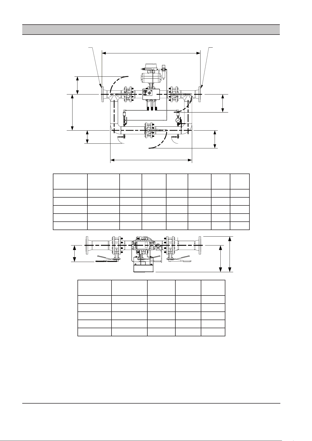
42 ingersollrandproducts.com
PARAGRAAF 21 AFMETINGEN VAN IX INTELLIFLOW “MILLIMETER”
( H )
BYPASS VALVE HANDLE
AT CLOSED POSITION
( J )
ISOLATION VALVE HANDLE
AT CLOSED POSITION
( H )
BYPASS VALVE HANDLE
AT CLOSED POSITION
( H )
BYPASS VALVE HANDLE
AT CLOSED POSITION
OUTLET CONNECTION “ P”
ANSI / DN PN10 RAISED
FACEFLANGE
INLET CONNECTION “ P”
ANSI / DN PN10 RAISED
FACEFLANGE
( E )
( D )
( A )
( N )
( G )
( C )
MODEL
CCN A D E H J P
NUMMER
IX50 23473242 959 803 375 270 175 50
IX80 23473259 1075 883 460 270 192 80
IX100 23473267 1438 1229 543 270 202 100
IX150 23473275 1572 1334 648 270 231 150
IX200 23473283 1716 1446 629 299 256 200
MODEL
CCN C G N
NUMMER
IX50 23473242 387 305 175
IX80 23473259 427 327 194
IX100 23473267 459 345 213
IX150 23473275 522 380 238
IX200 23473283 586 414 276
Page 91

( M )
( F )
( B )
( L )
( K )
BYPASS VALVE HANDLE
AT CLOSED POSITION
CUSTOMER ELECTRICAL
CONNECTION
22,23mm DIA. KNOCK OUT
MODEL
CCN B F K L M
NUMMER
IX50 23473242 860 390 102 260 305
IX80 23473259 980 409 102 279 391
IX100 23473267 1003 460 102 298 470
IX150 23473275 1303 505 102 333 578
IX200 23473283 1347 543 102 368 559
*OPMERKINGEN:
1) ALLE AFMETINGEN ZIJN IN INCH MET EEN TOLERANTIE VAN +/- 0,6 mm.
2) ALLE GEWICHTEN ZIJN IN KILOGRAM.
3) MAXIMALE NOMINALE DRUK: 14 BAR.
4) MAXIMALE NOMINALE TEMPERATUUR: 66 GRADEN C.
MODEL
CCN GEWICHT
NUMMER
IX50 23473242 82
IX80 23473259 118
IX100 23473267 200
IX150 23473275 295
IX200 23473283 390
ingersollrandproducts.com 43
Page 92

44 ingersollrandproducts.com
PARAGRAAF 22 LIJST VAN RESERVEONDERDELEN VOOR IX INTELLIFLOW
1 2 3
6
7
8
11
13
14B
14C
14A
15
16
14
4
5
10
12
4
5
12
9
12
12
17
A
DETAIL A
B
DETAIL B
INTELLIFLOW SPARE PARTS LIST
ITEM NOQTY
EA.
1 1 ALL 23451966 CONTROLLER KIT
2 1 ALL 634067 CABLE GLAND SET
3 2 ALL 634104 FUSE IEC 1.6A
4 2 ALL 634065 PRESSURE TRANSDUCER 0232 PSIG
5 2 IX02IX08 / IX08CDN 634069 ADAPTER BUSHING, 1/4” BSPP X 1/4” NPT
4 IX050IX200
6 1 ALL SEE TABLE
7 1 ALL SEE TABLE
8 1 ALL 633684 PRESSURE GAUGE, 2 1/2” DIA., 0200 PSIG
9 1 ALL 630022 EL, 1/4” MPT X 1/4” TUBE
10 1 ALL 630029 CONNECTOR, 1/4” MPT X 1/4” TUBE
11 4 ALL 699197 1/4” MANUALLY OPERATED BRASS BALL VALVE
12 VARIES ALL 630078 1/4” CONTROL AIR NYLON TUBING
13 1 IX02 / IX050 634029 2” BUTTERFLY VALVE WITH PNEUMATIC ACTUATOR
MODEL PART
DESCRIPTION
NUMBER
BELOW*
BELOW*
IX03 / IX080 634030 3” BUTTERFLY VALVE WITH PNEUMATIC ACTUATOR
IX04 / IX100 634031 4” BUTTERFLY VALVE WITH PNEUMATIC ACTUATOR
IX06 / IX150 634032 6” BUTTERFLY VALVE WITH PNEUMATIC ACTUATOR
IX08 / IX08CDN / IX200 634033 8” BUTTERFLY VALVE WITH PNEUMATIC ACTUATOR
FILTER REGULATOR 0 250 PSIG
FILTER REGULATOR FILTER ELEMENT
Page 93

ITEM NOQTY
EA.
13A 1 IX02 / IX050 634077 PNEUMATIC ACTUATOR
13B 1 ALL 634082 4-20mA ELECTRO PNEUMATIC POSITIONER
14 3 IX02 / IX050 634024 2” BUTTERFLY VALVE WITH MANUAL OPERATOR
15 16 IX02 / IX050 684355 5/811 X 4 1/2” LG HEX HD CAP SCREW
16 IX03 / IX080 684381 5/811 X 5” LG HEX HD CAP SCREW
32 IX04 / IX100
32 IX06 / IX150 684356 3/410 X 5 1/2” HEX HD BOLTS
32 IX08 / IX08CDN / IX200 684357 3/410 X 6” HEX HD BOLTS
16 VARIES IX02, IX03, IX04 / IX050,
32 IX06, IX08 / IX150 698746 3/410 HEX NUT
32 IX200 600300 3/410 HEX NUT
MODEL PART
DESCRIPTION
NUMBER
IX03 / IX080 634078 PNEUMATIC ACTUATOR
IX04 / IX100 634079 PNEUMATIC ACTUATOR
IX06 / IX150 634080 PNEUMATIC ACTUATOR
IX08 / IX08CDN / IX200 634081 PNEUMATIC ACTUATOR
IX03 / IX080 634025 3” BUTTERFLY VALVE WITH MANUAL OPERATOR
IX04 / IX100 634026 4” BUTTERFLY VALVE WITH MANUAL OPERATOR
IX06 / IX150 634027 6” BUTTERFLY VALVE WITH MANUAL OPERATOR
IX08 / IX08CDN / IX200 634028 8” BUTTERFLY VALVE WITH MANUAL OPERATOR
684250 5/811 HEX NUT
IX080, IX100
*Filter Regulator en Element Replacement
Referentie Controller Serienummer om de juiste vervangende onderdeel te identiceren:
IX Intelliow
Serienummer
Lower-504402 23467954 23474299 502007-Higher 15314719 15299662
Filter Regulator
Part No
Regulator Element
Part No.
IX Intelliow
Serienummer
Filter Regulator
Part No.
Regulator
Element Part
No.
ingersollrandproducts.com 45
Page 94

Page 95

Page 96

ingersollrandproducts.com
© 2011 Ingersoll-Rand Company
Page 97

Ingersoll Rand Automatisation du système
IX IntelliFlow
Manuel De L’opérateur
80445570
Révision D
Janvier 2012
DE
Bedienungshandbuch
EN
Operator’s Manual
ES
Manual De Operadores
FR
Manuel De L’utilisateur
IT
Manuale D’uso
NL
Gebruiksaanwijzingen
Veuillez conserver ces
instructions
Page 98

SECTION 1 TABLE DES MATIÈRES
Section 1 - tABLe DeS MAtiÈReS .............................2
Section 3 - intRoDUction ......................................3
Section 4 - SÉcURitÉ ................................................ 3
MESURES DE SÉCURITÉ .............................................3
INSPECTION / VERIFICATION A LA LIVRAISON
AVANT L’INSTALLATION ...........................................................3
INSTALLATION .............................................................................3
UTILISATION .................................................................................3
ENTRETIEN ET RÉPARATIONS ................................................4
Section 5 - conneXion et coMMAnDeS ............ 5
OPERATING MODES .................................................................5
Section 6 - inStALLAtion .........................................7
CARACTERISTIQUES TECHNIQUES DE IX
INTELLIFLOW ...............................................................................7
INSTALLATION DE L’IX INTELLIFLOW .................................8
ALIMENTATION EN ENERGIE DU BOITIER IX .................... 9
COMMANDE DE SOUPAPE DE IX INTELLIFLOW
RACCORDEMENT ET POSITIONNEMENT DU
CAPTEUR ....................................................................................... 9
BOITIER DE RESEAU RS485 IX ..............................................10
MENU D’ETALONNAGE DU CAPTEUR 3...........................19
MENU DE CONFIGURATION DE RELAIS 4 .......................20
Section 10 - DiAGnoSticS .....................................20
MENU DE DIAGNOSTIC 5 ......................................................20
Section 11 - coDeS D’eRReUR ..............................21
Section 12 - LiSte DeS PieceS DU
ReGULAteUR iX inteLLiFLoW .................................22
Section 13 - cARActeRiStiQUeS tecHniQUeS
DU ReGULAteUR iX inteLLiFLoW ...........................22
Section 14 - DiAGRAMMe De cABLAGe DU
ReGULAteUR iX inteLLiFLoW .................................23
MONTAGE DU COFFRET .......................................................25
Section 15 - intRAntS DU ReGULAteUR A
DiStAnce iX inteLLiFLoW ........................................26
FONCTIONS D’ENTREES DU BOITIER IX ..........................26
AUTOMATISATION DU RELAIS VIRTUEL .........................26
Section 16 - enReGiStReURS MoDBUS
RS485 DU ReGULAteUR iX. inteLLiFLoW .............27
Section 17 - PoSitionneUR nUMeRiQUe
De iX inteLLiFLoW .....................................................28
Section 7 - FonctionneMent De L’AFFicHAGe
et DU MenU .................................................................11
Section 8 - MiSe en RoUte ....................................13
INSPECTIONS PHYSIQUES ....................................................13
AFFICHAGE DE LA PRESSION ..............................................13
MODE DE FONCTIONNEMENT ...........................................13
POINTS DE CONSIGNE DE LA PRESSION ........................13
CARACTERISTIQUES ET FONCTIONS
OPTIONNELLES DU BOITIER IX ...........................................13
DÉMARRAGE DE IX INTELLIFLOW .....................................13
REGLAGE DES PARAMETRES DE MISE AU POINT ........14
Section 9 - conFiGURAtion DU SYSteMe .......15
AFFICHAGE ET FONCTIONNEMENT DU MENU ............15
ACCES AUX ECRANS DE CONFIGURATION DE IX ........15
PRÉSENTATION GÉNÉRALE DU MENU DE
CONFIGURATION ......................................................................16
MENU DE CONFIGURATION UTILISATEUR 1 ..................17
IX. PROCEDURE DE REGLAGE DU POSITIONNEUR
NUMERIQUE DE INTELLIFLOW ...........................................28
Section 18 - L’ActionneUR De iX inteLLiFLoW
oUVRe oU FeRMe PAR DeFAUt ...............................38
Section 19 - ScHeMA De PReSentAtion
GeneRALe DU BLoc iX. inteLLiFLoW ....................39
Section 20 - DiMenSionS DU BLoc iX
inteLLiFLoW “PoUceS” .............................................40
Section 21 - DiMenSionS DU BLoc iX
inteLLiFLoW “MiLLiMetReS” ...................................42
Section 22 - LiSte DeS PieceS De RecHAnGe
De iX inteLLiFLoW .....................................................44
SE RÉFÉRER À LA SECTION INDIQUÉE
NOTE
IMPORTANT OU AVERTISSEMENT,
SÉCURITÉ
MENU DE CIBLE DE PRESSION 2 ........................................19
2 Ingersoll Rand Automatisation du système IX IntelliFlow
ingersollrandproducts.com
Page 99
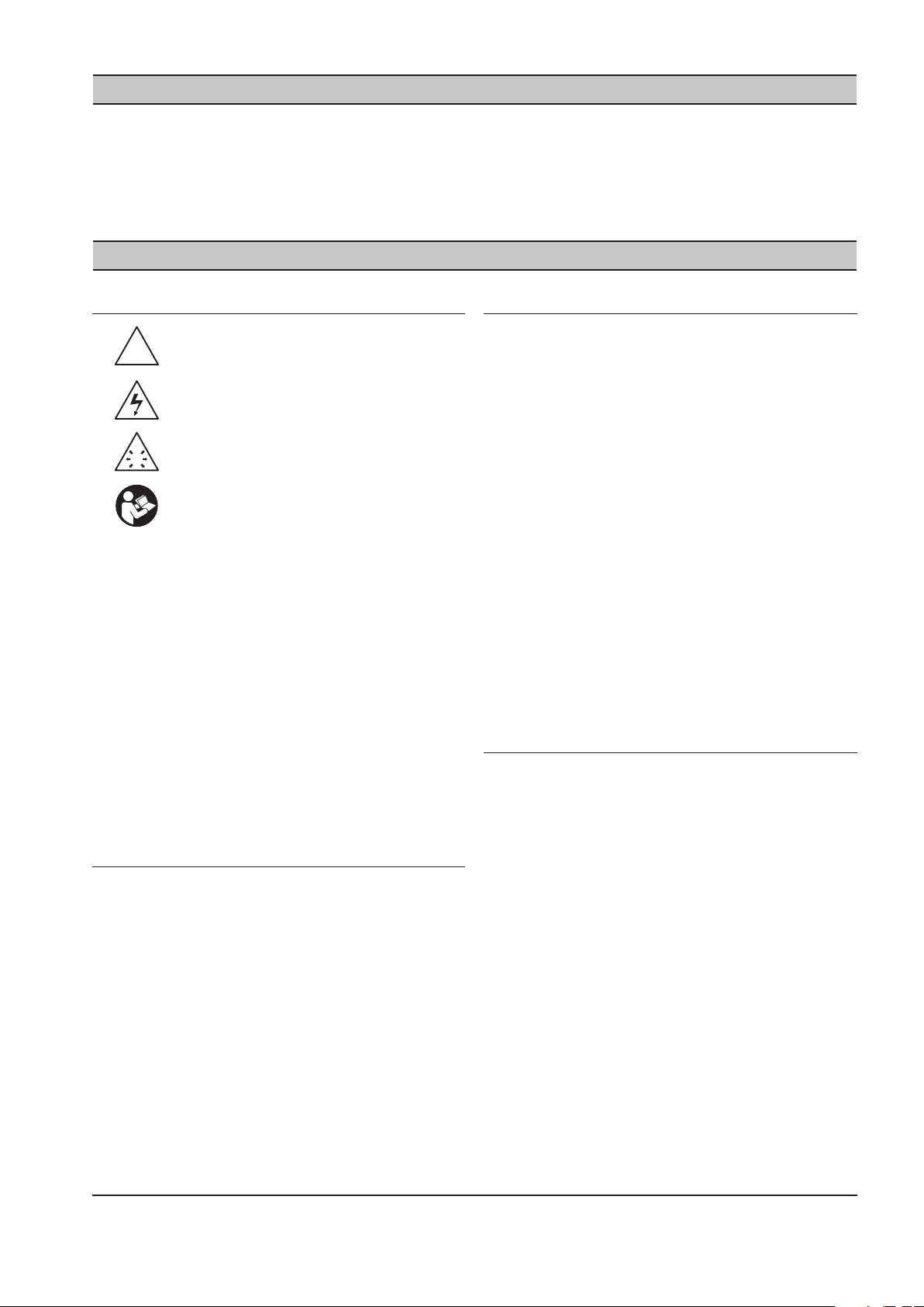
SECTION 3 INTRODUCTION
!
!
Le IX Intelliow est un système intermédiaire de
régulation qui régit la pression de l’air dans le système.
Le IX Intelliow peut régir l’Admission, la Production ou
un mélange des deux au moyen de consignes dénies
par l’utilisateur.
SECTION 4 SÉCURITÉ
MESURES DE SÉCURITÉ
AVERTISSEMENT : Danger
AVERTISSEMENT : Risque
d’électrocution
AVERTISSEMENT : Risque de haute
pression
AVERTISSEMENT : Consulter le manuel
Avant d’installer ou d’utiliser le IX IntelliFlow, prenez
•
le temps de lire attentivement toutes les instructions
du présent manuel, ainsi que celles des manuels
du compresseur et des diérents périphériques
susceptibles d’être installés ou raccordés à l’unité.
L’électricité et l’air comprimé peuvent provoquer de
•
graves blessures ou endommager les équipements.
L’opérateur doit faire appel à son bon sens et doit
•
utiliser de bonnes pratiques de travail lorsqu’il fait
fonctionner et entretient ce système. Tous les codes
applicables doivent être strictement respectés.
L’entretien doit être assuré par un personnel qualié
•
équipé des outils appropriés.
Le IX Intelliow est équipé d’un régulateur de type PID
(Boîtier IX) qui ajuste la soupape pour maintenir une
pression constante [+/- .75 PSI (0,05 bars)] si le volume
de stockage est approprié.
INSTALLATION
Le IX Intelliow ne doit être utilisé que par un
•
personnel compétent sous la direction de personnes
qualiées.
Un sectionneur à fusible / interrupteur d’isolation
•
doit être inséré entre la principale source
d’alimentation électrique et le IX Intelliow. Il doit
être positionné au voisinage immédiat du régulateur.
La consommation d’énergie du régulateur est
indiquée dans le présent manuel à la section relative
aux caractéristiques techniques du régulateur IX
Intelliow. L’installation de l’alimentation en énergie
doit être eectuée conformément aux codes
électriques en vigueur aux plans local et national.
Le IX Intelliow doit être positionné de manière à
•
permettre un accès sans obstacle ni danger pour
l’utilisation et l’entretien, et assurant à tout moment
une bonne visibilité des indicateurs.
Si des plates-formes surélevées sont requises
•
pour accéder à l’IX Intelliow, elles ne doivent pas
perturber son utilisation normale ni en gêner l’accès.
UTILISATION
Le IX Intelliow ne doit être utilisé que par un
•
personnel compétent sous la direction de personnes
qualiées.
INSPECTION / VERIFICATION A LA
LIVRAISON AVANT L’INSTALLATION
La caisse doit être inspectée après son arrivée pour
•
rechercher les dommages éventuels qui seraient
survenus pendant le transport.
Le bloc régulateur du ltre est expédiée sans être
•
raccordée au régulateur IX. Elle est emballée dans
une boite située sous le support de xation du
régulateur. Veuillez alerter l’expéditeur si cette
boîte est absente, ou si la caisse d’expédition a été
endommagée.
Une fois l’unité retirée de la caisse, et avant
•
l’installation, il est indispensable de resserrer tous
les boulons de connexion conformément aux
spécications correspondantes.
Ne jamais ôter ou modier les dispositifs protecteurs
•
de sécurité, ni les matériaux isolants montés sur l’IX
Intelliow.
Le IX Intelliow ne doit être utilisé que sous la
•
tension et la fréquence d’alimentation pour
lesquelles il a été conçu.
Lorsque l’alimentation principale est mise en service,
•
des tensions mortelles sont présentes dans les
circuits électriques et une prudence extrême est
nécessaire pour toute intervention sur l’unité.
Ne pas ouvrir les trappes d’accès ni toucher aux
•
composants électriques lorsque l’appareil est sous
tension, sauf en cas de nécessité pour eectuer
des mesures, des essais ou des réglages. Ce type
d’opération ne doit être réalisé que par un électricien
qualié équipé des outils appropriés et muni des
protections adéquates contre les risques électriques.
ingersollrandproducts.com 3
Page 100

4 ingersollrandproducts.com
Un panneau d’avertissement signalant que «
•
L’UNITÉ PEUT DÉMARRER SANS AVERTISSEMENT
» doit être apposé, à côté de l’écran d’achage,
sur tous les compresseurs d’air et/ou autres
équipements raccordés à l’unité.
Si un compresseur d’air et/ou tout autre
•
équipement raccordé à l’unité doit être démarré à
distance, apposer deux panneaux d’avertissement
sur l’équipement en question, signalant que «
CETTE UNITÉ PEUT ÊTRE DÉMARRÉE À DISTANCE ».
Mettre un panneau à l’extérieur de l’équipement,
à un emplacement visible par tous, et un autre à
l’intérieur, dans le compartiment de commande.
Le IX Intelliow est conçu pour être utilisé
•
avec des systèmes de souerie d’air sous une
pression maximale de 200 PSI (13.78 bars) à une
température maximale de 150OF (65OC).
L’utilisation de l’appareil dans d’autres
•
conditions que celles spéciées ci-dessus peut
l’endommager ou être cause de blessures. Un
dispositif de limitation de pression (p. ex., une
soupape de dégagement de pression) doit être
fourni et monté sur site dans le système de
souerie.
ENTRETIEN ET RÉPARATIONS
L’entretien, les réparations ou des modications
•
ne doivent être eectués que par des personnes
compétentes, sous la direction d’un personnel
qualié.
Si des pièces de rechange s’avèrent nécessaires,
•
n’utiliser que celles proposées par le fabricant de
l’équipement d’origine ou par un autre fournisseur
agréé.
Exécuter les opérations ci-après avant d’ouvrir ou
•
de retirer une trappe d’accès, ou d’eectuer un
travail quelconque sur le IX IntelliFlow:
i. Isoler le IX Intelliow de la source principale
d’alimentation en énergie. Verrouiller
l’interrupteur d’isolement en position “ARRÊT”
et retirer les fusibles.
ii. Coller des étiquettes du type «TRAVAIL EN
COURS - NE PAS METTRE L’UNITÉ SOUS
TENSION», sur l’interrupteur sectionneur ainsi
que sur l’unité. Ne pas rétablir l’alimentation
électrique ni tenter de démarrer le IX Intelliow
tant qu’une telle étiquette est visible.
S’assurer que toutes les instructions relatives à
•
l’utilisation et à l’entretien sont scrupuleusement
respectées et que l’ensemble de l’unité (avec ses
accessoires et dispositifs de sécurité) est maintenu
en bon état de marche.
La précision des appareils de détection doit être
•
vériée régulièrement. Ils doivent être étalonnés
en cas de dépassement des seuils de tolérance.
S’assurer toujours que la pression, à l’intérieur
du système à air comprimé, est libérée dans
l’atmosphère en toute sécurité avant d’essayer de
retirer ou d’installer un appareil de détection.
Le IX Intelliow ne doit être nettoyé qu’avec un
•
chion humide en n’utilisant, si nécessaire, que des
détergents doux. Éviter d’utiliser des substances
alcalines ou contenant des acides corrosifs.
Ne pas peindre la face avant du régulateur ni
•
d’altérer la visibilité des indicateurs, commandes,
instructions ou avertissements.
 Loading...