

Ingersoll-Rand SS815 Series, SS825 Series, SS850 Series Installation And Maintenance Manual

03531480
Form P6567
Edition 8
March, 1995
INSTALLATION AND MAINTENANCE MANUAL
for
SERIES SS815, SS825 AND SS850 STARTERS
IMPORTANT SAFETY INFORMATION ENCLOSED.
READ THIS MANUAL BEFORE OPERATING TOOL.
FAILURE TO OBSERVE THE FOLLOWING WARNINGS COULD RESULT IN INJURY.
For safety, top performance, and maximum
l
durability of parts, do not operate Series SS815,
SS825 and SS850 Starters at air pressures over the
pressure rating stamped on the nameplate. Use
supply lines of adequate size as directed in the
installation instructions in this manual.
Always turn off the air or gas supply and
disconnect the air supply hose before installing,
l
removing or adjusting any accessory on this starter,
or before performing any maintenance on this
•
starter.
Series SS815, SS825 and SS850 Starters are
designed for gas operation. They are not totally
sealed in dynamic operation since the exhaust must
be vented or piped away and there is a possibility of
leakage around the output shaft when rotating.
l
l
Caution should be taken when operating these
starters on gas because of the danger of fire,
explosion or inhalation. After assembling a starter,
always test it in accordance with the procedures
outlined in this manual. Never install a
reassembled starter that has not been tested in
accordance with the procedures in this manual
Operate this starter only when properly installed on
the engine.
Do not lubricate starters with flammable or volatile
liquids such as kerosene or jet fuel.
Do not remove any labels. Replace any damaged
label.
Use accessories recommended by Ingersoll-Rand.
The use of other than genuine Ingersoll-Rand replacement parts may result in safety hazards, decreased starter
performance and increased maintenance, and may invalidate all warranties.
Ingersoll-Rand is not responsible for customer modification of starters for applications on which Ingersoll-Rand was not
consulted.
Repairs should be made only by authorized, trained personnel.
Consult your nearest Ingersoll-Rand Authorized
Servicenter.
It is the responsibility of the employer to place the information in this manual into the hands of the operator.
Refer All Communications to the Nearest
Ingersoll-Rand Office or Distributor.
@Ingersoll-Rand Company 1995
Printed in U.S.A.
INGERSOLL-RAND®
ENGINE STARTING SYSTEMS

WARNING LABEL IDENTIFICATION
FAILURE TO OBSERVE THE FOLLOWING WARNINGS COULD RESULT IN INJURY.
WARNING
Always wear eye protection
when performing maintenance on this starter.
WARNING
Always turn off the air
supply and disconnect the
air supply hose before
installing, removing or
adjusting any accessory on
this starter, or before
performing any maintenance
on this starter.
WARNING
Always wear hearing
protection when testing this
starter.
WARNING
Do not use damaged, frayed
or deteriorated air hoses
and fittings.
For natural gas operation, starter main exhaust must be piped away.
To pipe the drive housing vent, remove the drive housing plug and replace it with a suitable tubing line.
The tubing
must vent at a safe location and must not be interconnected with any other exhaust lines which might introduce a back
pressure on the drive housing vent.
2

PLACING STARTER IN SERVICE
LUBRICATION
Proper lubrication is essential for top performance and
maximum durability of a Starter.
Two lubrication systems are recommended:
Ingersoll-Rand No. HDL2 Lubricator: For Starter
installations with cranking cycles of less than 10 seconds.
Install as shown in Dwg. TPB978. (See Installation of
HDL2 Lubricator on Page 5.) Lubricate with diesel fuel
or 1OW non-detergent motor oil.
When an HDL2 Lubricator is used, make certain that
the oil supply line pressure is no greater than 5 psi. If
there is pressure on the line, the Lubricator will
continuously leak lubricant through the Starter and out
the exhaust.
Ingersoll-Rand No. NE-244 In-Line Lubricator:
For Starter installations with cranking cycles more than 10
seconds. Install as shown in Piping Diagrams. Lubricate
with a good quality 1OW non-detergent motor oil. Adjust
the Lubricator to flow 1 to 3 drops per second.
INSTALLATION
For maximum performance, read this manual prior to
the installation or operation of Series SS815, SS825 and
SS850 Starters.
General Information
We recommend that on all vehicular installations and
on stationary engines subject to vibration that hoses of
the specified diameter be used instead of rigid pipe
connections to the starter. Vehicle and engine vibration
will soon loosen rigid pipe connections, whereas hoses
will absorb the vibration and connections will remain
tight.
This starter is designed for flange mounting at the inlet.
Allpiping, hoses and fittings must be clean and free of
dirt and foreign material during installation.
In the actual mounting of an Air Starter, it is best to
have the hose connections already made at the receiver,
and to have the starter end of the hose handy for
attaching to the Starter.
Engine design often demands that the starter be
mounted underneath in extremely close quarters, and
even though two of the mounting bolt holes are easy to
reach, the third one is often less accessible. To install a
starter, the following tools are required: a regular
ratchet wrench, sockets, universal joint, socket
extension and a single or double-end box wrench.
*
Registered trademark of Loctite Corporation.
5.
6.
The efficiency of an Air Starter can be greatly impaired
by an improper hook-up. Hoses smaller than those
recommended will reduce the volume of air to the
motor and the use of reducers for piped-away
applications in the exhaust port will restrict the exhaust
causing back pressure to the motor resulting in reduced
performance. The number of tees and elbows, and the
length of the supply line should be kept to a minimum.
Use l-1/2” #24 hose or pipe for supply lines up to 15
feet long; use 2” hose or pipe if the supply line is over
15 feet long.
A leak in any of the connections in live air liens means
that the system will drain overnight and will have to be
re-pressurized the next morning by use of another
vehicle or compressor. Make your connections bubble
tight to avoid unnecessary costs and delays. On all
threaded connections throughout the system, use
Ingersoll-Rand No. SMB-441 Sealant, non-hardening
No. 2 Permatex or LoctiteB* Pipe Sealant. Always run
your air supply line from the side or top of the
receiver, never at or near the bottom. Moisture in the
air collects at the bottom of the receiver resulting in
damage which could cause the valves to become
inoperative. Periodically, open the petcock at the
bottom of the tank to drain the water.
Orientation of the Air Starter
If the factory orientation will not fit your engine due to
radial location of the Drive Housing or location of the inlet
and/or exhaust ports, reorient the Starter as follows:
Look at the dimension illustration and note that the
Drive Housing (30) can be located in any one of
sixteen radial positions relative to the Gear Case (58).
The exhaust port (Motor Housing){ 1) can be located in
any one of four radial positions relative to the Gear
Case and the air inlet (Motor Housing Cover) can be
located in any one of four radial positions relative to
the exhaust port. Also, the Drive Housing can be
installed on the engine bell housing in any one of three
radial positions.
Do not separate the Drive Housing from the Gear
Case during orientation or installation.
Study the engine mounting requirements and determine
the required orientation of the Drive Housing relative
to the Gear Case. If the Drive Housing has to be
reoriented, remove the eight Drive Housing Cap
Screws (28) and rotate the drive housing to its required
position. Reinstall the Drive Housing Cap Screws and
tighten them to 28 ft-lb (38) Nm) of torque.
PLACING STARTER IN SERVICE
3
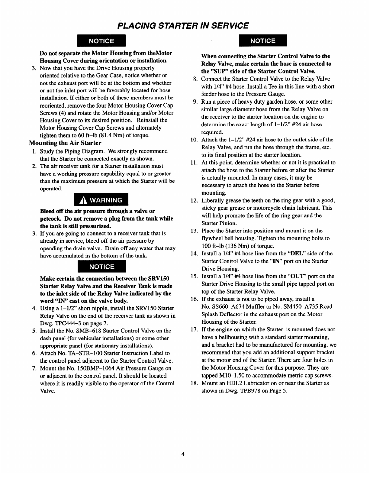
Do not separate the Motor Housing from the Motor
Housing Cover during orientation or installation.
Now that you have the Drive Housing properly
oriented relative to the Gear Case, notice whether or
not the exhaust port will be at the bottom and whether
or not the inlet port will be favorably located for hose
installation. If either or both of these members must be
reoriented, remove the four Motor Housing Cover Cap
Screws (4) and rotate the Motor Housing and/or Motor
Housing Cover to its desired position.
Reinstall the
Motor Housing Cover Cap Screws and alternately
tighten them to 60 ft-lb (8 1.4 Nm) of torque.
Mounting the Air Starter
Study the Piping Diagram. We strongly recommend
that the Starter be connected exactly as shown.
The air receiver tank for a Starter installation must
have a working pressure capability equal to or greater
than the maximum pressure at which the Starter will be
operated.
Bleed off the air pressure through a valve or
petcock. Do not remove a plug from the tank while
the tank is still pressurized.
If you are going to connect to a receiver tank that is
already in service, bleed off the air pressure by
opending the drain valve. Drain off any water that may
have accumulated in the bottom of the tank.
Make certain the connection between the SRV150
Starter Relay Valve and the Receiver Tank is made
to the inlet side of the Relay Valve indicated by the
word “IN” cast on the valve body.
Using a l-1/2” short nipple, install the SRVl50 Starter
Relay Valve on the end of the receiver tank as shown in
Dwg. TPC444-3 on page 7.
Install the No. SMB-618 Starter Control Valve on the
dash panel (for vehicular installations) or some other
appropriate panel (for stationary installations).
Attach No. TA-STR-100 Starter Instruction Label to
the control panel adjacent to the Starter Control Valve.
Mount the No. 150BMP-1064 Air Pressure Gauge on
or adjacent to the control panel. It should be located
where it is readily visible to the operator of the Control
Valve.
8.
9.
10.
11.
12.
13.
14.
15.
16.
17.
18.
When connecting the Starter Control Valve to the
Relay Valve, make certain the hose is connected to
the “SUP” side of the Starter Control Valve.
Connect the Starter Control Valve to the Relay Valve
with l/4” #4 hose. Install a Tee in this line with a short
feeder hose to the Pressure Gauge.
Run a piece of heavy duty garden hose, or some other
similar large diameter hose from the Relay Valve on
the receiver to the starter location on the engine to
determine the exact length of l-1/2” #24 air hose
required.
Attach the l-1/2” #24 air hose to the outlet side of the
Relay Valve, and run the hose through the frame, etc.
to its final position at the starter location.
At this point, determine whether or not it is practical to
attach the hose to the Starter before or after the Starter
is actually mounted. In many cases, it may be
necessary to attach the hose to the Starter before
mounting.
Liberally grease the teeth on the ring gear with a good,
sticky gear grease or motorcycle chain lubricant. This
will help promote the life of the ring gear and the
Starter Pinion.
Place the Starter into position and mount it on the
flywheel bell housing. Tighten the mounting bolts to
100 ft-lb (136 Nm) of torque.
Install a l/4” #4 hose line from the “DEL” side of the
Starter Control Valve to the “IN” port on the Starter
Drive Housing.
Install a l/4” #4 hose line from the “OUT” port on the
Starter Drive Housing to the small pipe tapped port on
top of the Starter Relay Valve.
If the exhaust is not to be piped away, install a
No. SS660-A674 Muffler or No. SM450-A735 Road
Splash Deflector in the exhaust port on the Motor
Housing of the Starter.
If the engine on which the Starter is mounted does not
have a bellhousing with a standard starter mounting,
and a bracket had to be manufactured for mounting, we
recommend that you add an additional support bracket
at the motor end of the Starter. There are four holes in
the Motor Housing Cover for this purpose. They are
tapped Ml0-1.50 to accommodate metric cap screws.
Mount an HDL2 Lubricator on or near the Starter as
shown in Dwg. TPB978 on Page 5.

PLAClNG STARTER lN SERVICE
19. Pressurize the complete starting system and check
every connection with a soap bubble test. There must
be no leaks.
BARRING OVER THE ENGINE
Occasionally, for setting injectors and/or for timing
purposes, it may be desirable to bar over the engine in such
a manner that any given piston can be stopped at any given
location. This is very easily done with a SS815, SS825 or
SS850 Starter.
1. Disconnect the l/4” #4 hose at the “OUT” port on the
Drive Housing, and plug the hole in the Drive Housing
with a l/4” pipe plug.
2. Remove the 3/8” pipe plug from the center of the
Motor Housing Cover.
3. Engage the Drive Pinion with the flywheel by applying
pressure to the
“IN” port on the Drive Housing.
4. Insert a 3/8” square drive wrench through the hole in
the Motor Housing Cover to engage the square drive
recess the rear of the Rotor.
5. Manually rotate the Rotor until the engine is cranked to
its desired position.
Installation of HDL2 Lubricator
AIR SUPPLY HOSE
LUBRICANT SUPPLY HOSE
The HDL2 Lubricator is self-priming and may be
installed directly on the Starter or located remotely.
Although the Lubricator is capable of drawing lubricant
from a source 4 ft (1.2 m) lower than the point of
installation, Ingersoll-Rand recommends installing the
Lubricator as close as possible to the oil source.
We recommend using the unpressurized fuel return line as
the source of lubricant. However, oil may be supplied
from a separate receiver or the diesel fuel tank. When the
diesel fuel tank is the lubricant source, install a 10 micron
to 50 micron fuel filter in the oil supply line at the fuel
tank. The lubricant supply line should be fed into the fuel
return line with the leg of the tee going to the lubricator
directed in the down direction to insure that the lubricator
does not draw air instead of oil.
Mount the HDL2 Lubricator as follows:
1. If you are going to mount the HDL2 Lubricator on the
Starter, remove one of the 3/8” pipe plugs from the
inlet boss on the Starter and replace it with the HDL2.
4,
LUBRICANT SUPPLY HOSE
TO STARTER AIR SUPPLY OR OIL CHAMBER
REMOTE INSTALLATION OF HDL2 LUBRICATOR
(Dwg. TP6978)
If you are going to mount the HDL2 at a remote
location, use two U-bolts and base clamp available for
the Lubricator.
If you mounted the HDL2 at a remote location, install a
l/4” #4 hose from the end of the Lubricator having
both a male and female thread to one of the 3/8” pipe
tapped holes on the Starter inlet boss.
Install a l/4” hose from the l/8” NPTF oil inlet in the
side of the HDL2 to the unpressurized fuel line, diesel
fuel tank or separate oil reservoir. Tighten the fitting at
the Lubricator to 15 to 36 ft-lb (20.3 to 40.8 Nm)
torque. The threads on the fitting must be clean;
assemble it without sealing compound or Teflon®*
tape.
Connection must be vacuum tight.
Before initial operation, manually fill the oil supply
line.
If a separate lubrication reservoir is used, fill it with
diesel fuel or a light motor oil such as SAE 10 or 10W.
* Registered trademark of E.I. DuPont de Nemans and Co., Inc.

PLACING STARTER IN SERVICE
Mounting Dimensions for Series SS815 and SS825 Starters
TPA1325-I)

PLACING STARTER IN SERVICE
Typical Vehicular Installation (Shown with SS815 Starter)
RELAY VALVE
AIR
RECEIVER
TANK
** FOR NATURAL GAS OPERATION, STARTER MAIN EXHAUST MUST BE
PIPED AWAY.
NOTE :
USE I-R SMB-441 SEALANT
ON ALL PIPE CONNECTIONS
TO PIPE THE DRIVE HOUSING VENT, REMOVE THE DRlVE HOUSING
PLUG AND REPLACE IT WITH A SUITABLE TUBING LINE.
AIR/GAS STARTER
THE TUBING MUST VENT AT A SAFE LOCATlON AND MUST NOT BE
1NTERCONNECTED WITH ANY OTHER EXHAUST LINES WHICH
SS660-A674 MUFFLER
OR SM450-A735 ROAD
SPLASH DEFLECTOR
VENT INTRODUCE A BACK PRESSURE ON THE DRIVE HOUSlNG
.
(Dwg. TPC444-4)
Typical Stationary Installation (Shown with SS815 Starter)
STANDARD HIGH PRESSURE SYSTEM
AIR OR GAS.
USE WHEN SUPPLY
PRESSURE IS OVER PRESSURE RATING
OF STARTER
(Dwg. TPA842-2)

PLACING STARTER IN SERVICE
Typical Installation with Engine Prelube System
STARTER CONTROL
Typical Installation with Engine Prelube System when Supply Pressure
is over Rated Starter Pressure
TO PIPE THE DRIVE HOUSING VENT, REMOVE THE DRIVE HOUSING
PLUG AND REPLACE IT WITH A SUITABLE TUBING LINE.
THE TUBING MUST VENT AT A SAFE LOCATION AND MUST NOT BE
INTERCONNECTED WITH ANY OTHER EXHAUST LINES WHICH
MIGHT INTRODUCE A BACK PRESSURE ON THE DRIVE HOUSING
VENT.
(Dwg. TPA844-2)
 Loading...