

Page 1
M35
41
ARO
Tool Products
OPERATOR’S MANUAL
INCLUDING: OPERATION, INSTALLATION & MAINTENANCE
SECTION
MANUAL
Released: 6-1-96
3/4” CAPACITY IMPACT WRENCH
Model: WG068A-F4-( )
The ARO WG068A-F4 3/4” Impact Wrench is designed for use in the construction industry and
in the production of heavy equipment such as locomotive, bulldozers, tractors and ships.
ARO is not responsible for customer modification of tools for applications on which ARO was
not consulted.
IMPORTANT SAFETY INFORMATION ENCLOSED.
READ THIS MANUAL BEFORE OPERATING TOOL.
IT IS THE RESPONSIBILITY OF THE EMPLOYER TO PLACE THE INFORMATION
IN THIS MANUAL INTO THE HANDS OF THE OPERATOR.
FAILURE TO OBSERVE THE FOLLOWING WARNINGS COULD RESULT IN INJURY.
PLACING TOOL IN SERVICE
Always operate, inspect and maintain this tool in accordance with American National Standards Institute
Safety Code for Portable Air Tools (ANSI Bl86.1)
For safety, top performance, and maximum durability
of parts, operate this tool at 90 psig (6.2 bar/620 kPa)
maximum air pressure at the inlet with 3/4” (19 mm)
inside diameter air supply hose.
Always turn off the air supply and disconnect the air
supply hose before installing, removing or adjusting
any accessory on this tool, or before performing any
maintenance on this tool.
Do not use damaged, frayed or deteriorated air hoses
and fittings.
Be sure all hoses and fittings are the correct size and
are tightly secured. See Dwg. TPD905-1 for a typical
piping arrangement.
Always use clean, dry air at 90 psig (6.2 bar/620 kPa)
maximum air pressure. Dust, corrosive fumes and/or
excessive moisture can ruin the motor of an air tool.
Do not lubricate tools with flammable or volatile liquids such as kerosene, diesel or jet fuel.
Do not remove any labels. Replace any damaged label.
USING THE TOOL
l
Always wear eye protection when operating or performing maintenance on this tool.
.
Always wear hearing protection when operating this
tool.
.
Keep hands, loose clothing and long hair away from
rotating end of tool.
.
Note the position of the reversing lever before operating the tool so as to be aware of the direction of rotation when operating the throttle.
.
Anticipate and be alert for sudden changes in motion
during start up and operation of any power tool.
.
Keep body stance balanced and firm. Do not overreach when operating this tool. High reaction torques
can occur at or below the recommended air pressure.
.
Tool shaft may continue to rotate briefly after throttle
is released.
.
Air powered tools can vibrate in use. Vibration,
repetitive motions or uncomfortable positions may be
harmful to your hands and arms. Stop using any tool
if discomfort, tingling feeling or pain occurs. Seek
medical advice before resuming use.
.
Use accessories recommended by ARO.
.
Use only impact sockets and accessories. Do not use
hand (chrome) sockets or accessories.
.
Impact wrenches are not torque wrenches. Connections requiring specific torque must be checked with a
torque meter after fitting with an impact wrench.
.
This tool is not designed for working in explosive atmospheres.
.
This tool is not insulated against electric shock.
The use of other than genuine ARO replacement parts may result in safety hazards, decreased tool performance,
and increased maintenance, and may invalidate all warranties.
Repairs should be made only by authorized trained personnel. Consult your nearest ARO Tool Products Authorized
Servicenter.
For parts and service information, contact your local ARO distributor, or the Customer Service Dept. of the Ingersoll-Rand Distribution Center,
White House, TN at PH: (615) 6724321, FAX: (615) 672-0601
ARO Tool Products
Ingersoll-Rand Company
1725 U.S. No. 1 North l P.O. Box 8000 l Southern Pines, NC 283884000
©1996 INGERSOLL-RAND COMPANY. PRINTED IN U.S.A.
ARO
Part of worldwide Ingersoll-Rand
Page 2
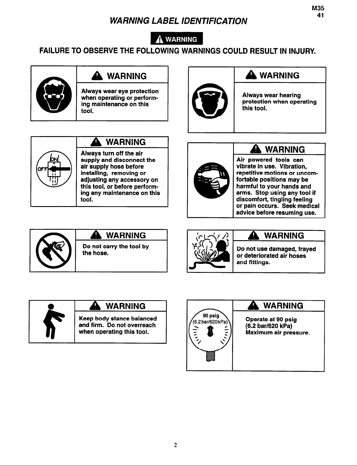
WARNING LABEL IDENTIFICATION
FAILURE TO OBSERVE THE FOLLOWING WARNINGS COULD RESULT IN INJURY.
WARNING
Always wear eye protection
when operating or performing maintenance on this
tool.
WARNING
Always turn off the air
supply and disconnect the
air supply hose before
installing, removing or
adjusting any accessory on
this tool, or before performing any maintenance on this
tool.
WARNING
Do not carry the tool by
the hose.
WARNING
Always wear hearing
protection when operating
this tool.
I
WARNING
Air powered tools can
vibrate in use. Vibration,
repetitive motions or uncomfortable positions may be
harmful to your hands and
arms. Stop using any tool if
discomfort, tingling feeling
or pain occurs. Seek medical
advice before resuming use.
I
WARNING
Do not use damaged, frayed
or deteriorated air hoses
and fittings.
2
Page 3
PLACING TOOL IN SERVICE
@35
41
LUBRICATION
IRAX
No. 50 IRAX No. 100
Always use an air line lubricator with these tools.
We recommend the following Filter-Lubricator-Regulator
Unit:
For USA - IRAX No. C31-06-G00
For International - IRAX No. FRL30-C6-A29
After each eight hours of operation, unless an air line
lubricator is used, inject approximately 1 to 2 cc of
IRAX No. 50 Oil into the air inlet before attaching the air
hose.
After each forty-eight hours of operation, or as
experience indicates, inject about 4 cc of IR4X No. 100
Grease into the Grease Fitting (12).
INSTALLATION
Air Supply and Connections
Use clean, dry air at 90 psig maximum. Dust, corrosive
fumes and/or excessive moisture can ruin the motor of an
air tool. An air line filter can greatly increase the life of an
air tool. The filter removes dust and moisture.
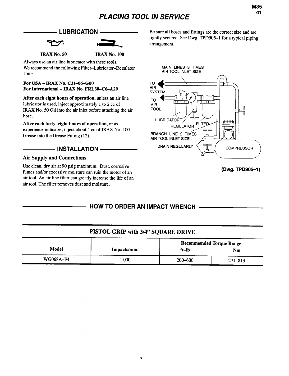
Be sure all hoses and fittings are the correct size and are
tightly secured. See Dwg. TPD905-1 for a typical piping
arrangement.
MAIN LINES 3 TIMES
AIR TOOL INLET SIZE
TO
AIR
SYSTEM
BRANCH LINE 2 TIMES
AIR TOOL INLET SIZE
DRAIN REGULARLY
I I
COMPRESSOR
(Dwg. TPD905-1)
Model
WG068A-F4
HOW TO ORDER AN IMPACT WRENCH
PISTOL GRIP
Impacts/min.
with
1000
3/4” SQUARE DRIVE
Recommended Torque Range
ft-lb
200-600
Nm
271-813
3
Page 4
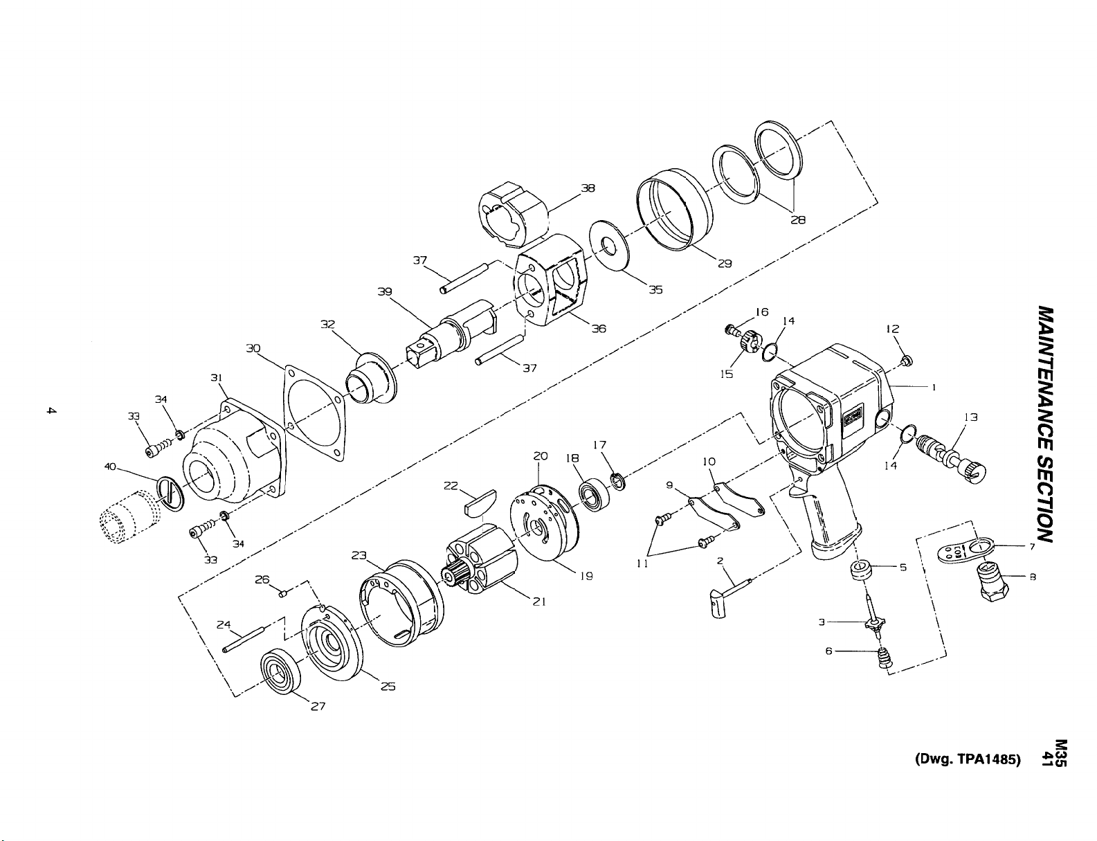
MAINTENANCE SECTION
Page 5

+ 3
+ 5
+ 6
l
10
11
12
13
l
14
15
16
+ 17
4 18
19
+ 20
21
+ 22
23
24
25
26
+ 27
PART NUMBER FOR ORDERING
1
Motor Housing Assembly
2
7
8
9
Trigger Assembly
Throttle Valve
Throttle Valve Seat
Throttle Valve Spring
Exhaust Deflector
Inlet Bushing
Housing Plate
Housing Plate Gasket
Housing Plate Screw (2)
Grease Fitting
Reverse Valve
Reverse Valve Seal (2)
Reverse Valve Knob
Reverse Valve Knob Screw
Rear Rotor Bearing Retainer
Rear Rotor Bearing
Rear End Plate
.......................
Rear End Plate Gasket
Rotor ..............................
Vane Packet (set of 6 Vanes)
Cylnder
Cylinder Dowel
Front End Plate
End Plate Dowel
............................
......................
......................
.....................
Front Rotor Bearing
..............
..................
....................
.................
...............
.................
.....................
.....................
...............
............
.....................
.....................
..............
................
............
...................
.................
............
...................
..........
VW-1083
2920P-A93
DG230-302
DG230-303
1720P-51
1720P-23
2920P-465
1720P-230
172OP-231
FEAl00-112
13OSR-188
1710B-329
261-283
23l-666
23l-665
MVA008-218
4E-510
2920-12
2920B-283
2910B-53
2910-42-6
2920-3
910-98
2920-l1
2920-74
834-24
PART NUMBER FOR ORDERING
28
Motor Clamp Washer (2)
29
Motor Retainer
l
30
Hammer Case Gasket
31
Hammer Case Assembly
.........................
.................
....................
for models ending in -EU .......
32
*
for all other models
Hammer Case Bushing
Hammer Case Label
............
...............
for models ending in -EU .......
for all other models
33
Hammer Case Cap Screw (4)
34
Cap Screw Lock Washer (4)
35
Rear Hammer Frame Washer
36
Hammer Frame Assembly
37
38
39
40
*
*
Hammer Pin (2)
Hammer
Anvil
..............................
................................
Socket Retainer
Horizontal Hanger
Nameplate
.....................
........................
......................
............
..............
..............
..............
................
for models ending in -EU .......
for all other models
*
Tune-up Kit (includes illustrated parts
............
3, 5, 6, 10, 14 [2], 17, 18, 20, 22,
27, and 30) ............................
2920-207
2920B-800
910-36
VW-1086EU
VW-1086
2920-641
EU-99
WARNING-2-99
34U-103
T11-58
910-706
2910-A703
1910-704
260-724
260-726
RRl0034S
910-366
VW-l087-EU
VW-1087
1720P-TK2
* Not illustrated.
+ Indicates Tune-up Kit Part.
Page 6

MAINTENANCE SECTION
Always wear eye protection when operating or
performing maintenance on this tool.
Always turn off the air supply and disconnect the air
supply hose before installing, removing or adjusting any
accessory on this tool, or before performing any
maintenance on this tool.
LUBRICATION
Each time a WG068A-F4 Impact Wrench is disassembled
for maintenance and repair or replacement of parts,
lubricate the tool as follows:
1.
Work approximately 12 to 15 cc of IRAX No. 100
Grease into the impact mechanism, particularly around
the Hammer Pins (37), Hammer (38), Hammer Frame
(36), Anvil (39) and inside the Hammer Case Bushing
(32).
2.
Work some IRAX No. 100 Grease into the Rear Rotor
Bearing (18) and Front Rotor Bearing (27).
3.
Inject approximately 4 cc of IRAX No. 100 Grease
into the Grease Fitting (12).
4.
Wipe a thin film of IRAX No. 50 Oil on the Rotor (2 1),
Vanes (22), Reverse Valve (13), Rear End Plate (19),
Front End Plate (25) and the bore of the Cylinder (23).
5.
Use IRAX No. 50 Oil for lubrication the motor. Inject
approximately 1 to 2 cc of oil into the air inlet before
attaching the air hose.
DISASSEMBLY
M35
41
2. Unscrew and remove the four Hammer Case Cap
Screws (33).
3. While lightly tapping on the end of the Anvil (39) with
a plastic hammer, lift off the Hammer Case (3 1) and
remove the Hammer Case Gasket (30).
4. Grasp the Hammer Frame (36) and carefully lift off the
entire impact mechanism, making certain not to drop
the two Hammer Pins (37).
Disassembly of the Impact Mechanism
1. Set the mechanism, driver end up, on the workbench.
Using a felt tipped pen, mark one end of the Hammer
“?” with the arrow pointing upward.
2. With the mechanism sitting upright on the workbench,
slowly rotate the Anvil in a clockwise direction until it
comes up solid.
If you continue to rotate the Anvil, it will cam the
Hammer out of engagement. Don’t do this; merely
rotate the Anvil until it comes up solid.
3. Hold the Hammer Frame (38) firmly and, without
disturbing the Hammer, gently lift the Anvil from the
Hammer Frame.
4. With the Anvil removed, lift out the two Hammer Pins
(37).
The Hammer is now free to slide from the Hammer
Frame. Be careful not to drop it.
General Instructions
1.
Do not disassemble the tool any further than necessary
to replace or repair damaged parts.
2.
Whenever grasping a tool or part in a vise, always use
leather-covered or copper-covered vise jaws to protect
the surface of the part and help prevent distortion. This
is particularly true of threaded members and housings.
3.
Do not remove any part which is a press lit in or on a
subassembly unless the removal of that part is
necessary for repairs or replacement.
4.
Do not disassemble the tool unless you have a
complete set of new gaskets and G-rings for
replacement.
2.
Slide assembled motor out of Motor Housing.
Disassembly of the Impact Wrench
1. Clamp the handle of the tool in leather-covered or
copper-covered vise jaws with the square driver
upward.
* Registered trademark of Loctite Corporation.
Disassembly of the Reverse Valve
1. Unscrew the Reverse Valve Knob Screw (16) and
remove the Reverse Valve Knob (15).
This Screw is installed with LoctiteB*. You may
have to heat the Screw slightly to loosen it.
2. While slowly rotating the Reverse Valve (13),
withdraw it from the reverse valve bushing in the
Motor Housing. Remove the Housing from the vise.
Disassembly of the Motor
1. Grasp the Motor Retainer (29) and lift it from the
Motor Housing (1).
2. Lift the Rear Hammer Frame Washer (35) and the two
Motor Clamp Washers (28) from the front of the motor.
3. Grasping the spline of the Rotor (21), carefully lift the
assembled motor from the Motor Housing.
Page 7

MAINTENANCE SECTION
The End Plate Dowel (26) will be free to move when
the the Front End Plate (25) clears the Housing. Do
not lose it.
Remove the Rear End Plate Gasket (20).
4.
5.
Slide the Front End Plate and Front Rotor Bearing (27)
from the Rotor.
Remove the Cylinder Dowel (24), Cylinder (23) and
6.
Vanes (22) from the Rotor.
Using snap ring pliers, remove the Rear Rotor Bearing
7.
Retainer (17) and slide the Rear End Plate (19) and
Rear Rotor Bearing (18) from the Rotor.
If the Front Rotor Bearing or Rear Rotor Bearing
8.
requires replacement, press it from the End Plate with
an arbor press.
Disassembly of the Throttle Mechanism
Unscrew the Inlet Bushing (8) and remove the Exhaust
1.
Deflector (7), Throttle Valve Spring (6) and the
Throttle Valve (3).
The Trigger (2) will be free to fall out of the
Housing when the Throttle Valve is removed.
Do not lose it.
If the Throttle Valve Seat (5) requires replacement,
2.
insert a hooked tool through the center of the Valve
Seat. Catching the backside of the Seat with the hook,
pull the Seat from the Housing.
Remove the two Housing Plate Screws (11) and the
3.
Housing Plate (9) if the Housing Plate Gasket (10)
needs to be replaced.
ASSEMBLY
General Instructions
Always press on the
1.
when installing the bearing on a shaft.
Always press on the
2.
when pressing the bearing into a bearing recess.
Whenever grasping a tool or part in a vise, always use
3.
leather-covered or copper-covered vise jaws. Take
extra care with threaded parts and housings.
Always clean every part and wipe every part with a
4.
thin film of oil before installation.
inner
ring of a ball-type bearing
outer
ring of a ball-type bearing
M35
41
Apply a film of G-ring lubricant to all G-rings before
5.
final assembly.
Assembly of the Throttle Mechanism
1.
If the Housing Plate (9) was removed, position the
Housing Plate Gasket (10) and Housing Plate, convex
side first, against the Motor Housing (1). Apply
Vibra-TiteB** to the two Housing Plate Screws (11)
and secure the Plate and the Gasket with the Screws.
Tighten the Screws to 20 to 25 in-lb (2 to 3 Nm)
torque.
2.
If the Throttle Valve Seat (5) was removed, drop the
Seat into the air inlet chamber in the handle. Install a
new Throttle Valve Seat by pushing it into position
against the shoulder in the air inlet chamber with a 5/8”
(16 mm) dowel.
3.
Wipe the stem of the Trigger Assembly (2) with some
light grease and insert the stem into the trigger
bushing.
4.
Installation of the Throttle Valve (3) is sometimes a bit
tricky due to the smallness of the Valve and the depth
of the bore in which it is located. The difficult part is
in holding the Valve while inserting the long end of the
valve stem through the hole in the trigger stem.
Although the Valve can be held with a push-button
mechanical pencil or a wooden dowel, one of the
easiest ways of holding it is by using a common
wooden pencil with a rubber eraser. Insert the short
end of the valve stem into the rubber eraser, as far as
possible, and then back it out until the Valve is
nicely supported. Insert the Valve into the bore of the
handle so that the long end of the stem enters the hold
in the trigger stem. Pull outward on the Trigger to hold
the Valve while removing the pencil.
5.
Install the Throttle Valve Spring (6), small end first.
6.
Position the Exhaust Deflector (7) in the recess at the
bottom of the handle and install the Inlet Bushing (8).
Tighten the Bushing to 40 to 45 ft-lb (54 to 61 Nm)
torque.
Assembly of the Reverse Valve
1. After applying G-ring lubricant to the Reverse Valve
Seals (14), install them in the undercuts in the reverse
valve bushing. Make certain they are properly seated.
2. Dampen the Reverse Valve (13) with IRAX No. 50 Oil.
With the tool in an upright position, and while facing
the back end of the tool, insert the Reverse Valve from
left to right into the reverse valve bushing.
just
Registered trademark of ND Industries.
**
7
Page 8

MAINTENANCE SECTION
M35
41
3. Place the Reverse Valve Knob (15) on the end of the
Valve and, after applying LoctiteB No. 601 to the
Reverse Valve Knob Screw (16), fasten the Knob to the
Valve with the Screw. Tighten the Knob Screw to 5 to
6 ft-lb (6.75 to 8.15 Nm) torque.
Assembly of the Motor
1.
Using a sleeve that will contact only the outer ring of
the bearing, press the Front Rotor Bearing (27) into the
Front End Plate (25) and the Rear Rotor Bearing (18)
into the Rear End Plate (19).
2.
Slip the Font End Plate and Bearing over the splined
hub of the Rotor (21).
3.
Grasp the splined end of the Rotor in leather-covered
or copper-covered vise jaws with the Rotor in a
vertical position.
Dampen each Vane (22) with IRAX No. 50 Oil and
insert a Vane into each vane slot in the Rotor.
Set the Cylinder (23) over the Rotor and onto the Front
End Plate.
Slide the Rear End Plate and Bearing onto the Rotor
hub and against the Cylinder.
7.
Using snap ring pliers, install the Rear Rotor Bearing
Retainer (17) in the groove on the rotor hub.
8.
Align the dowel hole in both End Plates with the one
through the Cylinder, and insert a guide rod 3/16”
diameter x 8” long (4.7 mm diameter x 203 mm long)
through the holes. Allow the rod to protrude about
3-l/2” (89 mm) from the Rear End Plate.
9.
While holding the assembled motor intact, remove it
from the vise.
10. Insert the protruding end of the guide into the cast slot
at the bottom of the Motor Housing bore and slide the
assembled motor along the rod until it is completely
seated in the housing.
11. Remove the guide rod and install the Cylinder Dowel
(24).
12. Install the End Plate Dowel (26).
13. Grasp the handle of the Motor Housing in
leather-covered or copper-covered vise jaws with the
open end of the Motor Housing upward.
14. Place a Motor Clamp Washer (28), concave side first,
down over the hub of the Front End Plate so that the
outer rim of the Washer contacts the Front End Plate.
Place the second Motor Clamp Washer, convex side
first, down over the hub of the Front End Plate so that
the inner rims of both Washers are in contact but the
outer rims are separated.
15.
Place the Motor Retainer (29), small bore first, down
over the hub of the Front End Plate and against the
outer rim of the second Motor Clamp Washer.
16.
Place the Rear Hammer Frame Washer (35), hub side
first, over the hub of the Rotor and against the Front
Rotor Bearing.
Assembly of the Impact Mechanism
1.
Coat the Hammer (38) with a light film of IRAX
No. 100 Grease.
2.
Slide the Hammer into the Hammer Frame (36) exactly
as it was when you marked it prior to disassembly.
In order to utilize both impacting surfaces on the
Hammer and thus equalize the wear on each
hammer jaw, the Hammer can be flipped over so
that the arrow is pointing downward.
3.
Replace the Hammer Pins (37).
4.
Examine the base of the Anvil (39) and note its
contour. While looking down through the Hammer
Frame, swing the Hammer to its full extreme one way
or another until you can match the contour of the
Anvil. Enter the Anvil into the Hammer Frame and
through the Hammer.
Assembly of the Tool
1. Set the assembled impact mechanism down over the
splined hub of the Rotor.
2. Position the Hammer Case Gasket (30) on the Housing.
3. Work approximately 12 to 15 cc of IRAX No. 100
Grease into the impact mechanism.
4. Smear a thin film of IRAX No. 100 Grease on the
inside surface of the Hammer Case Bushing (32), and
place the Hammer Case (3 1) down over the Anvil and
against the Motor Retainer.
5. Install the Hammer Case Cap Screws (33) and tighten
them to 20 to 25 ft-lb (27 to 34 Nm) torque.
6. Remove the Impact Wrench from the vise and inject
2 to 4 cc of IRAX No. 100 Grease into the Grease
Fitting (12).
8
Page 9

Double
Low power
Motor will not run
Tool will not impact
MAINTENANCE SECTION
TROUBLESHOOTING GUIDE
I
Dirty Inlet Bushing or Air
Strainer Screen and/or Exhaust
Silencer Bushing and Exhaust Silencer.
Worn or broken Vanes
Worn or broken Cylinder and/or
scored End Plates-
Dirty motor parts
Improper positioning of Reverse
Valve
Incorrect assembly of motor
Insufficient lubricant in the
impact mechanism
Broken or worn impact
mechanism parts
Impact mechanism not assembled
correctly
Probable Cause
Using a suitable cleaning solution, in a well
ventilated area, clean Air Strainer Screen, Inlet
Replace complete set of Vanes.
Examine Cylinder and replace it if it is worn or
broken or if bore is scored or wavy. Replace End
Plates if they are scored.
Disassemble tool and clean all parts with a
suitable cleaning solution, in a well-ventilated area.
Reassemble tool as instructed in this manual.
Make certain that Reverse Valve is fully
engaged to the left or right.
Disassemble motor and replace worn or broken
parts and reassemble as instructed.
Remove Hammer Case Assembly and lubricate
impact mechanism.
Remove Hammer Case and examine impact
mechanism parts. Replace any worn or broken
parts.
Refer to Assembly of the Impact Mechanism.
Solution
M35
41
SAVE THESE INSTRUCTIONS. DO NOT DESTROY.
9
Page 10

NOTES
M35
41
Page 11

NOTES
M35
41
Page 12

M35
41
ARO
Part of worldwide Ingersoll-Rand
PN49999-525
 Loading...