

Page 1
OPERATOR’S MANUAL
INCLUDING: OPERATION, INSTALLATION & MAINTENANCE
ALSO INCLUDE MANUALS: 67075--X--B CART (PN 97999-1018), 6544X-X AIR MOTOR (97999-064), R272X1-XXX REGULATOR
(100400-006), , 65184X-X FOLLOWER PLATE (97999-605) & S-636 GENERAL INFORMATION (PN 97999-636).
650239--X--B & 650240--X--B
PUMP AND CART ASSEMBLY
(4-1/4” AIR MOTOR - 9:1 RATIO)
READ THIS MANUAL CAREFULLY BEFORE INSTALLING,
OPERATING OR SERVICING THIS EQUIPMENT.
It is the responsibility of the employer to place this information in the hands of the operator. Keep for future reference.
650239--X--B
650240-X-B
RELEASED: 1-13-10
(REV. 01)
SERVICE KITS
x Use only genuine ARO replacement parts to assure compatible
pressure rating and longest service life.
x 61268
x 637058
x 637059
for repair of air motor section.
for repair of lower pump section (Leather).
for repair of lower pump section (PTFE).
PUMP SYSTEM DATA
Model Series 650239-1- -B & 650240....................
System Type Air operated, 2-ball double...................
acting cart mounted pump
Basic Pump 65814-X-C....................
Ratio 9:1.........................
Air Motor 65445-B......................
Motor Repair Kit 61268................
Motor Diameter 4-1/4” (10.8 cm)................
Stroke 4” (10.2 cm).......................
Air Inlet 1/2” - 14 N.P .T.F. - 1 (female)......................
Lower Pump End Series 65965-X..........
Lower Pump Repair Kit 63705X...........
Material Outlet 3/4” - 14 N.P .T.F. - 1 (female)................
OPERATING AND SAFETY PRECAUTIONS
WARNING
INCLUDED FOR OPERATING AND SAFETY PRECAUTIONS
AND OTHER IMPORTANT INFORMATION.
WARNING
SURE OF 1350 P.S.I. (93 BAR) AT 150 P.S.I. (10.3 BAR) AIR INLET PRESSURE.
WARNING
AL OPERATINGAND SAFETY PRECAUTIONS AND OTHER IMPORTANT INFORMATION.
READ THE GENERAL INFORMATION MANUAL
DO NOT EXCEED MAXIMUM OPERATING PRES-
REFER TO THE PUMP MANUAL FOR ADDITION-
IMPORT
This is one of the eight documents which support the pump. Replacement copies of these forms are available upon request.
= 650239 MODEL OPERATOR’S MANUAL
- GENERAL INFORMATION - PUMPING SYSTEMS
- 67075--X--B CARTS MANUAL (PN 97999-1018)
- 6544X-X AIR MOTOR OPERATOR’S MANUAL (PN 97999-064)
- 65184X-X FOLLOWER PLATE OPERATOR’S MANUAL (PN
97999-605)
ANT
(PN 97999-636)
MODEL DESCRIPTION CHART
PUMP (1) PUMP LOWER
PACKAGE
650239--X--B 65814-X--C 65965--X
650240--X--B 65814-X--C 65965--X
MODEL NO. PUMP END
AIR AND LUBE REQUIREMENTS
x Excessive air pressure will shorten the life of the pump. Do not oper-
ate pump above recommended maximum air pressure.
Formaximum operating efficiency,the followingair supply specification should be maintained to this pump:
x AIR PRESSURE - Refer to maximum pressure note in Operat-
ing Precautions.
x AIR FILTRATION - 50 micron
x LUBRICATED AIR SUPPLY
x AIR INLET SIZE - 1/2” N.P.T.F. - 1
x Filtered and oiled air will allow the pump to operate more efficiently
and yield a longer life to operating parts and mechanisms.
INGERSOLL RAND COMPANY LTD
209 NORTH MAIN STREET – BRYAN, OHIO 43506
(800) 495-0276
www.ingersollrandproducts.com
FAX(800) 892-6276
© 2011 CCN 15330053
Page 2
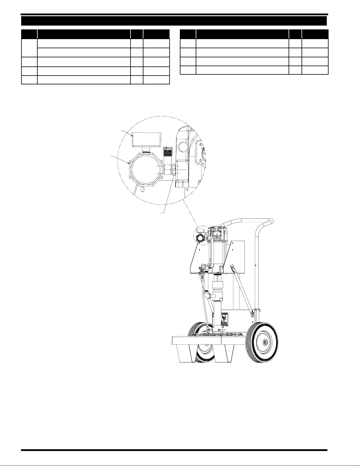
PARTS LIST
Item Description (Size in inches)
1 Pump Assembly (650239-B & 650240-B) (Leather) (1)
(650239-1-B & 650240-1-B) (PTFE)
(650239-4-B & 650240-4-B) (UHMW - PE) (1) 65814-4-C
Qty
Part No. Item Description (Size in inches)
65814-C
(1) 65814-1-C
2 Cart Assembly (See Operator’s Manual) (1) 67075-1-B
3 Screw (3/8” - 16 x 5/8” long) (4) Y6-62-C
104500 Gauge
R37221--100 Regulator
Qty
Part No.
4 Follower Plate (See Operator’s Manual) (1) 651840-1
5 Nipple (3/4” x 3” long) (1) Y44-43-N
6 90_ Elbow (3/4”) (2) Y43-15-N
7 Nipple (3/4” x 7” long) (1) Y44-50-N
Y45--5-- C Bushing
PAGE2OF4
650239- X- B
Page 3
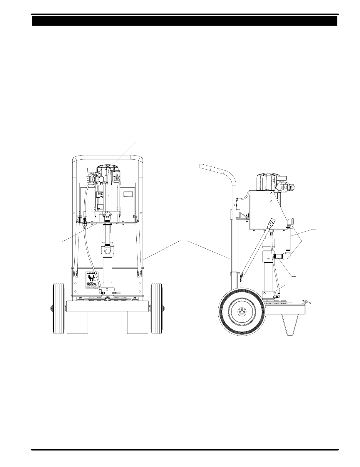
PARTS LIST
1
7
3
2
6
5
4
PAGE3OF4650239- X- B
Page 4
OPERATING PROCEDURES
x
x
x The 9:1 ratio is an expression of the relationship between the effec-
tive air motor area and the effective lower pump area. When 120 PSI
(10 bar) of air pressure is supplied to the air motor, the lower pump
end will develop a maximum of 1,350 PSI (93 bar) of fluid pressure
(at no flow) as the fluid control is opened, the flow rate will increase
as the air motor cycle rate increases to keep up with the demand.
x Flush system. This pump has been tested in kerosene and a small
amount remains in the pump end. Kerosene must be flushed from
the pump before using. To flush system:
x Gun or dispensing device should be removed.
x Immersefluid or suction hose in a 5 gallon pail of compatible solvent.
x Place material outlet hose into pail.
x Regulate air pressure to a few pounds.
x Connect air supply to air motor inlet.
x Allow pump to cycle slowly and circulate solvent for awhile.
x Disconnect air supply.
x To Prime System:
x Install gun or dispensing device to material outlet hose.
x A shut-off valve located on the cart should be in the “off” position
(handle perpendicular to valve body). Connect air line to connector
(See figure 1).
x With air line connected to connector, the lift assembly and pump will
rise.
x Once lift assembly and pump are in the “up” position, place and cen-
ter opened 5 gallon pail of material under follower plate (5).
x Remove vent plug from follower plate (5). Trapped air must be re-
moved from beneath the follower plate.
x Disconnect the main air line to the connector and allow pump and lift
assembly to lower into 5 gallon pail of material. Once the follower
plate (5) begins to force material out of the vent plug, reseat bleed
plug.
x Once the follower has been properly seated, prior to pumping, be
sure the thumb screws on the cart are tightened to secure 5 gallon
pail. Pail must be locked in place with thumb screws before the follower plate can be removed from 5 gallon pail.
x Djustment knob on air regulator (1) should be turned counter-clock-
wise until it turns free to prevent overpressurizing the pump.
x Connect air line to air regulator (1). Adjust knob on the air regulator
(1) until pump begins to cycle.
x Trigger (13) gun to prime pump with material.
x If pump does not stop or material does not flow from dispensing
valve, refer to Troubleshooting Section of this manual.
x Refer to Disassembly Procedures of air motor for correct break
down.
x Disassembly should be done on a clean work bench with clean
cloths to keep parts clean.
x If replacement parts are necessary, consult drawing containing
parts for identification.
x Before assembling, lubricate parts where required. When assem-
bling “O” rings or parts adjacent to “O” rings, care must be exercised
to prevent damage to “O” rings and “O” ring groove surfaces.
MAINTENANCE
x When the following instructions are observed, heavy paste materi-
als can be pumped directly from their original 5 gallon pail without air
inclusion, or excessive waste. The follower plate creates an air tight
seal as well as clean-wiping action in its progressive downward
movement into the pail.
x Lubricate lower follower wiper plate seal with any type grease (sili-
cone, vaseline, gear, etc.). This ensures a smooth fit into the pail as
well as prevents curing type compounds from bonding to the seal.
x Check vent plug to be sure it easily threads in and out. It is recom-
mended to lubricate the threads of the plug to help prevent possible
set up of compound at this point. See 65184X-X Operator’s Manual.
TO CHANGE THE PAIL
x Turn knob on pump air regulator (1) counter-clockwise to turn air
“off” to pump.
x Turn shut-off control valve to “ON” position (Handle parallel with
body) to apply pressure under follower plate.
x Disconectmain air line from pump air regulator (1) and connect to air
line connector on cart.
x Allow pump and lift assembly to clear the top of the 5 gallon pail of
material.
x Turn shut-off controll valve tp “OFF” postition. (Handle perpendicu-
lar to valve body).
x Unscrew thumb screws. Remove empty pail of material and replace
with a new pail of material.
x Secure new pail of material with thumb screws. Remove vent plug
from follower plate (5).
x Disconnect main air line from connector and allow lift assembly to
lower into new 5 gallon pail of material. Once the (5) follower plate
begins to force material out of the vent plug, reseat bleed plug.
DAILY MAINTENANCE
x Lack of or an excessive amount of lubeication will affect the perfor-
mance and life of this pump. Use only recommended lubricants.
x DAILY - Fill air line lubricator reservoir with SAENO. 90W non-deter-
gent gear oil.
x If pump is to be inoperative for more than a few hours at a time, dis-
connect air supply and relieve all pressure from the system.
x Thismanual covers the basic pump unit. The 4-1/4” air motor is com-
pletely separate from the lower pump end. This helps to keep the air
motor from being contaminated by material being pumped.
x Periodically flush entire pump system with a solvent that is compat-
ible with the material being pumped.
x Keep solvent cup filled with this compatible solvent. This will keep
material from drying on the piston rod, which would drag thru the
packings, ruin them and eventually scour the piston rod.
PAGE4OF4
TROUBLESHOOTING
x Malfunctions beyond the scope of this manual should be brought to
the attention of your ARO Representative.
PROBLEM
- Cause, Solution
No material coming from extrusion nozzle
- Obstructed Material, Remove tip and clean
- Obstructed Hose, Remove control handle and cycle pump until hose
is clear
- Obstructed Control Handle, Disassemble control handle and clean
PN 97999-1218
650239- X- B
 Loading...