

Ingersoll-Rand 3940P2Ti Maintenance Information

80183387
Edition 1
January 2006
Air Impact Wrench
3940P2Ti
Maintenance Information
Save These Instructions

2 80183387_ed1
WARNING
Always wear eye protection when operating or performing maintenance on this tool.
Always turn off the air supply and disconnect the air supply hose before installing, removing or adjusting any accessory on this tool, or before
performing any maintenance on this tool.
Note: When reading the instructions, refer to exploded diagrams in Parts Information Manuals when applicable (see under Related
Documentation for form numbers).
Lubrication
Each time a Model 3940P2Ti Impactool is disassembled for maintenance
and repair or replacement of parts, lubricate the tool as follows:
1. Work approximately 6 cc of Ingersoll-Rand No. 170 Grease into the
impact mechanism. Coat the Anvil (40) lightly with grease around the
Hammer Case Bushing (42). Inject approximately 6 cc of grease into
the Grease Fitting.
2. Inject approximately 3 cc of No. 10 oil into the air inlet before
attaching the air hose.
Disassembly
General Instructions
1. Do not disassemble the tool any further than necessary to replace or
repair damaged parts.
2. Whenever grasping a tool or a part in a vise, always use leathercovered or copper-covered vise jaws to protect the surface of the
part and help prevent distortion. This is particularly true of threaded
members and housings.
3. Do not remove any part which is a press fit in or on a subassembly
unless the removal of that part is necessary for repairs or
replacement.
4. Do not disassemble the tool unless you have a complete set of new
gaskets and O-rings for replacement.
Disassembly of the Impactool
1. Clamp the handle of the Impactool in a vise with the square drive
upward.
2. Remove Exhaust Deflector (4) and Silencer (5).
3. Unscrew and remove the four Hammer Case Cap Screws (45).
4. While lightly tapping on the end of the Anvil (40) with a plastic
hammer, lift off the Hammer Case Assembly (41).
5. Remove the Hammer Case Gasket (36).
6. Grasp Hammer Frame (37) and carefully lift off entire impact
mechanism, making certain not to drop the two Hammer Pins (38).
Disassembly of the Impact Mechanism
1. Set the mechanism, driver end up, on the workbench.
NOTICE
Note the twin Hammers (39) within the Hammer Frame
Assembly (37). These are identical but must be placed in
the Hammer Frame Assembly in a certain relationship.
Using a felt-tipped pen, mark the top Hammer “T↑” and
the bottom Hammer “B↑” with the arrows pointing
upward. Mark both hammers on the same end.
2. With mechanism sitting upright on the workbench, slowly rotate
Anvil (40) in a clockwise direction until it comes up solid.
NOTICE
If you continue to rotate the Anvil, it will cam the
Hammers out of engagement. Do not allow this to
happen; merely rotate the Anvil until it comes up solid.
3. Hold the Hammer Frame firmly and, without disturbing Hammers,
gently lift the Anvil, simultaneously rotating it counterclockwise about
1/8 of a turn, from the Hammer Frame.
NOTICE
The twin Hammers will be free to slide from the Hammer
Frame when the Hammer Pins (38) are removed. Do not
drop the Hammers.
4. With Anvil removed, lift out the two Hammer Pins (38).
5. Remove the twin Hammers.
Disassembly of the Reverse Valve
1. Unscrew the four Housing Cover Cap Screws (25) and remove the
Housing Cover Assembly (21), Housing Cover Gasket (27), and
Motor Clamp Washer (26).
2. Grasp the Reverse Lever (20) and withdraw the Reverse Valve
Assembly (18) from the Motor Housing Assembly (1), taking care not
to lose the Reverse Lock Plunger (23) and Reverse Lock Plunger
Spring (24).
Disassembly of the Motor
1. While holding the Impactool over the workbench, turn Impactool
to bring the square drive side upward. This will allow the motor parts
to slide out of the Motor Housing Assembly (1). If the motor parts do
not slide out freely, gently tap the side of the Motor Housing
Assembly with a plastic hammer to jar them loose. Often, all of the
motor parts except the Front End Plate (34) and Cylinder (33) will
slide out easily. Tap the Motor Housing to remove the Front End Plate
and Cylinder.
2. Inspect the Vanes (32) for wear. If a Vane is chipped or otherwise
damaged, replace the complete set.
3. Check the bore of the Cylinder and the faces of the End Plates for
scoring. Replace any scored parts.
4. Remove two Air Port Gaskets (16) and Air Port Gasket Retainers
(17) from Housing.
Disassembly of the Throttle Mechanism
1. Place the tool on the workbench with the handle pointing toward you
and the square drive side upward. Use a punch to tap out the Throttle
Valve Assembly Retaining Pin (15) from the right to the left hand side
of the handle. Pull upward on the Trigger (7) to remove the complete
Throttle Valve Assembly (6).
2. Punch out the Trigger Retaining Pin (14) from the Throttle Valve
Bushing Assembly (8) to separate Throttle Valve Assembly (6) from
the Throttle Valve Bushing Assembly.
Assembly
General Instructions
1. Always press on the inner ring of a ball-type bearing when installing
the bearing on a shaft.
2. Always press on the outer ring of a ball-type bearing when pressing
the bearing into a bearing recess.
3. Whenever grasping a tool or part in a vise, always use leathercovered or copper-covered vise jaws. Take extra care with threaded
parts and housings.
4. Always clean every part and wipe every part with a thin film of oil
before installation.
5. Apply a film of O-ring lubricant to all O-rings before final assembly.
80183387_ed1 3
Assembly of the Throttle Mechanism
1. Apply O-ring lubricant to the O-rings and place them on the Throttle
Valve Bushing (8), large ring on the large diameter grooves, the two
smaller rings in the smaller grooves.
2. Insert the Throttle Valve Assembly (6), small end first, into the small
diameter of the Throttle Valve Bushing.
3. Align the slot in the Throttle Valve Assembly with the slot in the
Throttle Valve Bushing and replace the Trigger Retaining Pin (14).
Press on the Trigger (7).
4. Place the Impactool on the workbench with the handle pointing
toward you and the square drive upward. Align the hole in the
Throttle Valve Bushing Assembly with the hole in the Housing and
drive in the Throttle Valve Assembly Retaining Pin (15) from left to
right.
Assembly of the Motor
NOTICE
Periodically, as experience indicates and always after
disassembly, clean the air strainer screen in the Inlet
Bushing (3). Torque the Inlet Bushing to 50 to 60 ft-lb (68
to 81 Nm).
Before assembling the Motor, wipe a thin film of oil on the Rotor (31), End
Plates (30 and 34), Cylinder (33), and Vanes (32).
1. Using a sleeve that will contact only the outer ring of the Front Rotor
Bearing (35), press the bearing into the Front End Plate (34).
2. Slide the Front End Plate (34), bronze face first, over the splined hub
of the Rotor (31).
3. Stand the assembled Rotor and End Plate upright, grasping the
splined rotor hub with leather-covered or copper-covered vise jaws.
4. Place a Vane (32) in each vane slot in the Rotor.
5. Slide the Cylinder (33) down over the Rotor, aligning the holes in the
Cylinder with those in the Front End Plate.
6. Using a sleeve that will contact only the outer ring of the Rear Rotor
Bearing (29), press the bearing into the Rear End Plate (30).
7. Using a sleeve that will contact only the inner ring of the Rear Rotor
Bearing, press the assembled bearing and end plate onto the short
hub of the Rotor.
8. Before installing the Motor Assembly in the Motor Housing (1), be
certain that the Air Port Gaskets (16) and Gasket Retainers (17) are
in good condition and positioned with large open end down in the
recess in the Motor Housing.
9. Using a 3/16” x 8” rod, insert the rod through the Cylinder Dowel
Holes in both End Plates and Cylinder. This will hold all the motor
parts in alignment. Allow the 3/16” rod to protrude from the Front End
Plate far enough to enter the dowel hole at the bottom of the bore of
the Motor Housing.
10. Put the rod into the Dowel Hole in the Motor Housing, then slide the
assembled Motor into the Housing. Remove the rod and install the
Cylinder Dowel (28).
11. Place the Motor Clamp Washer (26) concave side first, over the hub
of the Rear End Plate so that the outer rim of the Washer contacts
the End Plate.
Assembly of the Reverse Valve
1. Dampen the Reverse Valve Seal (19) with O-ring lubricant and install
the Seal in the groove on the Reverse Valve Assembly (18).
2. Slide the Reverse Valve Assembly into the Motor Housing
Assembly (1).
3. Aligning the flats on the Reverse Lever (20) with those on the
Reverse Valve Assembly, slide the Reverse Lever on the Reverse
Valve Assembly. Place the Housing Cover Gasket (27) on the Motor
Housing.
4. Put the Reverse Lock Spring (24) followed by the Reverse Lock
Plunger (23) in the small hole at the bottom of the Housing Cover
Assembly (21).
5. Install the Motor Housing Cover (21). Tighten the Motor Housing
Cover Cap Screws to 10 to 12 ft-lb (14 to 16 Nm).
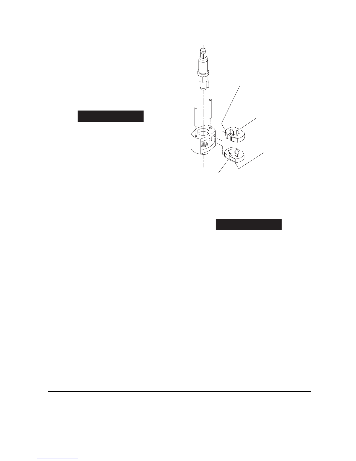
Assembly of the Impact Mechanism
(Dwg. TPD652)
1. Coat Hammers (39) with a light film of Ingersoll-Rand
Grease No. 170.
2. Replace Hammers in the Hammer Frame Assembly (37) exactly as
they were when you marked them prior to disassembly.
NOTICE
If you are installing new Hammers, or want to change
the location of the existing Hammers to utilize both
impacting surfaces, slide the Hammers in the Hammer
Frame so that the half-round notch on one Hammer is
located on one side of the Frame and the half-round
notch on the other Hammer is located on the other side
of the Frame.
Each Hammer is undercut on one side. When properly
installed in the Hammer Frame, these undercuts must
face each other.
3. Replace Hammer Pins (38).
4. Examine base of Anvil (40) and note its contour. While looking down
through Hammer Frame, swing the top Hammer to its full extreme
one way or other until you can match the contour of the Anvil. Put the
Anvil into the Hammer Frame and through the first Hammer. Swing
the bottom Hammer in opposite direction from the top Hammer and
maneuver Anvil slightly until it drops through the bottom Hammer.
Assembly of the Impactool
1. Secure Impactool in vise.
2. Set assembled hammer mechanism onto rotor shaft spline.
3. Place Hammer Case Gasket (36) over mechanism and against face
of Motor Housing.
4. Grease Anvil and top of Hammer Frame.
5. Reinstall the Hammer Case Assembly (41).
6. Assemble Dead Handle (44) to Dead Handle Bracket (43). Insert two
Hammer Case Cap Screws (45). Position assembly against
Hammer Case and thread the Screws into Housing.
7. Secure the Hammer Case Assembly with four Hammer Case Cap
Screws (45). Tighten to 20-25 ft-lb (27-34 Nm) torque.
8. Install a new Exhaust Silencer (5) in Motor Housing Assembly (1)
and install the Exhaust Deflector (4).
Cap Screw Specifications
Tighten the Hammer Case Cap Screws to a minimum of 20 ft-lb (27.1 Nm) torque.
Tighten the Housing Cover Cap Screws to a minimum of 10 ft-lb (13.5 Nm) torque.
TOP HAMMER
WIDE BEVEL UP
TOP HAMMER
HALF–ROUND NOTCH ON RIGHT
BOTTOM HAMMER
WIDE BEVEL DOWN
BOTTOM HAMMER
HALF–ROUND NOTCH ON LEFT
 Loading...