

Page 1

03542388
Form P7058
Edition 8
June, 2000
F
E
OPERATION AND MAINTENANCE MANUAL FOR
MODELS 180PQ1, 280P AND 280PQ1
P
TWIN BLADE IMPULSE WRENCHES
Models 180PQ1, 280P and 280PQ1 Impulse Wrenches are designed for use in assembly
operations requiring consistent torque. They are ideally suited to appliance assembly and
applications requiring low noise levels.
Ingersoll–Rand is not responsible for customer modification of tools for applications on which
Ingersoll–Rand was not consulted.
IMPORTANT SAFETY INFORMATION ENCLOSED.
READ THIS MANUAL BEFORE OPERATING TOOL.
IT IS THE RESPONSIBILITY OF THE EMPLOYER TO PLACE THE INFORMATION
IN THIS MANUAL INTO THE HANDS OF THE OPERATOR.
FAILURE TO OBSERVE THE FOLLOWING WARNINGS COULD RESULT IN INJURY.
PLACING TOOL IN SERVICE
• Always operate, inspect and maintain this tool in
accordance with American National Standards
Institute Safety Code for Portable Air Tools
(ANSI B186.1).
• For safety, top performance, and maximum durability
of parts, operate this tool at 90 psig (6.2 bar/620 kPa)
maximum air pressure at the inlet with 3/8” (10 mm)
inside diameter air supply hose.
• Always turn off the air supply and disconnect the air
supply hose before installing, removing or adjusting
any accessory on this tool, or before performing any
maintenance on this tool.
• Do not use damaged, frayed or deteriorated air hoses
and fittings.
• Be sure all hoses and fittings are the correct size and
are tightly secured. See Dwg. TPD905–1 for a typical
piping arrangement.
• Always use clean, dry air at 90 psig maximum air
pressure. Dust, corrosive fumes and/or excessive
moisture can ruin the motor of an air tool.
• Do not lubricate tools with flammable or volatile
liquids such as kerosene, diesel or jet fuel.
• Do not remove any labels. Replace any damaged label.
USING THE TOOL
• Always wear eye protection when operating or
performing maintenance on this tool.
• Always wear hearing protection when operating this
tool.
• Keep hands, loose clothing and long hair away from
rotating end of tool.
• Anticipate and be alert for sudden changes in motion
during start up and operation of any power tool.
• Keep body stance balanced and firm. Do not
overreach when operating this tool. High reaction
torques can occur at or below the recommended air
pressure.
• Tool shaft may continue to rotate briefly after throttle
is released.
• Air powered tools can vibrate in use. Vibration,
repetitive motions or uncomfortable positions may be
harmful to your hands and arms. Stop using any tool
if discomfort, tingling feeling or pain occurs. Seek
medical advice before resuming use.
• Use accessories recommended by Ingersoll–Rand.
• Use only impact sockets and accessories. Do not use
hand (chrome) sockets or accessories.
• This tool is not designed for working in explosive
atmospheres.
• This tool is not insulated against electric shock.
The use of other than genuine Ingersoll–Rand replacement parts may result in safety hazards, decreased tool performance, and
increased maintenance, and may invalidate all warranties.
Repairs should be made only by authorized trained personnel. Consult your nearest Ingersoll–Rand Authorized Servicenter.
Refer All Communications to the Nearest
Ingersoll–Rand Office or Distributor.
Ingersoll–Rand Company 2000
Printed in U.S.A.
Page 2
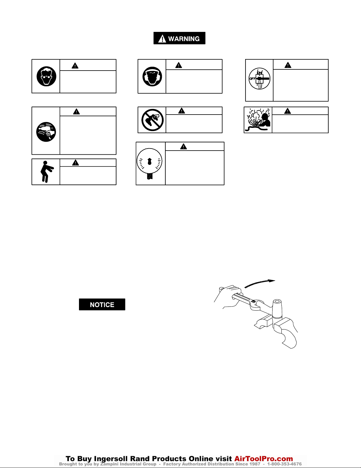
WARNING LABEL IDENTIFICATION
FAILURE TO OBSERVE THE FOLLOWING WARNINGS COULD RESULT IN INJURY.
WARNING
Always wear eye protection
when operating or performing maintenance on this
tool.
WARNING
Air powered tools can vibrate
in use. Vibration, repetitive
motions or uncomfortable positions may be harmful to your
hands and arms. Stop using
any tool if discomfort, tingling
feeling or pain occurs. Seek
medical advice before resuming use.
90 psig
(6.2bar/620kPa)
WARNING
Keep body stance balanced
and firm. Do not overreach
when operating this tool.
ADJUSTMENTS
TORQUE ADJUSTMENT
To adjust the torque on these Twin Blade Impulse Wrenches,
proceed as follows:
1. Remove the Adjustment Hole Plug.
2. Rotate the Drive Shaft until the Torque Adjustment Screw
is visible in the opening.
WARNING
Always wear hearing
protection when operating
this tool.
WARNING
Do not carry the tool by
the hose.
WARNING
Operate at 90 psig (6.2 bar/
620 kPa) Maximum air pressure.
3. Using copper–covered vise jaws, carefully grasp the flats
of the Mechanism Cover with the output end of the Drive
Shaft downward.
4. Using an adjustable wrench, unscrew the the Motor
Housing Assembly from the Mechanism Cover. This is a
left–hand thread, rotate the Motor Housing clockwise to
remove it. See Dwg. TPD1264.
WARNING
Always turn off the air supply and disconnect the air
supply hose before installing, removing or adjusting
any accessory on this tool,
or before performing any
maintenance on this tool.
WARNING
Do not use damaged, frayed
or deteriorated air hoses
and fittings.
3. Using a 1.5 mm hex wrench, rotate the Adjustment Screw
clockwise to increase the torque output and
counterclockwise to decrease the torque output. Do not
rotate the Oil Plug.
Make all final adjustments at the job.
4. Replace the Adjustment Hole Plug.
CHANGING THE MECHANISM FLUID
To change the Mechanism Fluid in the Impulse Mechanism,
proceed as follows:
1. For model 180PQ1 or 280PQ1, use a pointed probe to to
push the Spring Seat against the Retaining Sleeve Spring.
While the Spring is compressed, use another pointed
probe or thin blade screwdriver to remove the Retaining
Ring. Lift the Spring Seat, Spring and Bit Retaining
Sleeve off the Drive Shaft and remove the Bit Retaining
Ball.
2. Remove the Rubber Housing Boot.
CLOCKWISE TO LOOSEN
(Dwg. TPD1264)
5. Lift the assembled motor off the Mechanism Cover and
pull the mechanism assembly out of the Cover.
6. Using a 1.5 mm hex wrench, rotate the Torque
Adjustment Screw clockwise until the Screw stops.
Rotate the Screw counterclockwise until it stops or makes
six complete revolutions.
7. Using the special Tee Wrench furnished in the Tool Kit
(Part No. 180PQ–99), remove the Oil Plug and Oil Plug
Seal.
2
Page 3
ADJUSTMENTS
8. With the oil plug opening downward over a container,
rotate the Drive Shaft to purge the fluid from the
mechanism.
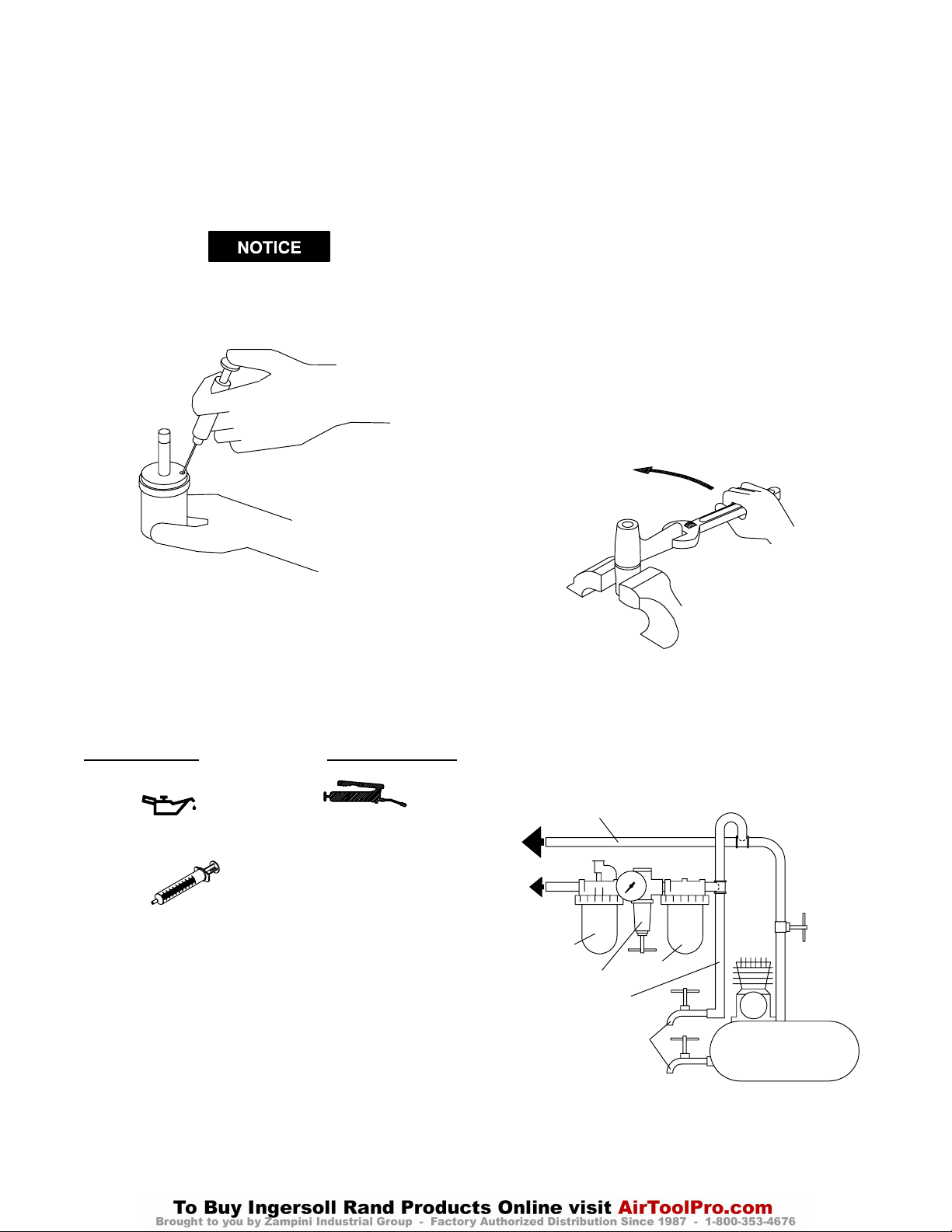
9. Using the syringe and fluid from the Fluid Replacement
Kit (Part No. EQ106S–K400), fill the mechanism with
the fluid furnished in the Kit.
See Dwg. TPD1265.
DO NOT SUBSTITUTE ANY OTHER FLUID.
Failure to use the fluid provided could damage the
tool, increase maintenance and decrease performance.
Use only clean fluid in these tools.
12. Using a 1.5 mm hex wrench, turn the Torque Adjustment
Screw clockwise until it stops. This is the maximum
torque position.
13. Wipe the outside of the mechanism dry and clean and
remove the Oil Chamber Plug. Using the syringe,
withdraw .25 cc of fluid from 180PQ1 models and
.3 cc of fluid from 280P and 280PQ1 models.
14. Install the Oil Chamber Plug and tighten it between 20
and 25 in–lb (2.3 and 2.8 Nm) torque.
15. Insert the mechanism assembly, output end leading, into
the Mechanism Cover clamped in the vise jaws.
16. Insert the hex end of the rotor shaft into the hex recess at
the rear of the Drive Shaft and thread the assembled
Motor Housing onto the Mechanism Cover. This is a
left–hand thread. Rotate the Housing counter–
clockwise to tighten it. See Dwg. TPD1266.
COUNTERCLOCKWISE TO TIGHTEN
(Dwg. TPD1265)
10. Submerge the fill opening in the remainder of the fluid,
and using a wrench, rotate the Drive Shaft to purge any
remaining air from the system.
11. Thread the Oil Plug with the Oil Plug Seal into the
mechanism until it is snug.
PLACING TOOL IN SERVICE
LUBRICATION
Ingersoll–Rand No. 50 Ingersoll–Rand No. 67
Ingersoll–Rand Fluid Part
No. EQ106S–400–1
Always use an air line lubricator with these tools.
We recommend the following Filter–Lubricator–Regulator
Unit:
For USA – No. C18–03–FKG0–28
After each 20 000 cycles, or as experience indicates, drain
and refill the Impulse Unit Drive Assembly as instructed
in this manual using the Fluid Replacement Kit (Part
No. EQ106S–K400). Lubricate the hex drive and the output
shaft before assembly.
MAIN LINES 3 TIMES
AIR TOOL INLET SIZE
TO
AIR
SYSTEM
TO
AIR
TOOL
LUBRICATOR
REGULATOR
BRANCH LINE 2 TIMES
AIR TOOL INLET SIZE
DRAIN REGULARLY
(Dwg. TPD1266)
FILTER
COMPRESSOR
(Dwg. TPD905–1)
3
Page 4

HOW TO ORDER AN IMPULSE WRENCH
Model Free Speed Recommended Torque Range
Soft Draw Hard Slam
ft–lb Nm ft–lb Nm
PISTOL GRIP with 1/4” INSERT BIT CHUCK
180PQ1 10,500 6–11 8–15 14–22 19–30
PISTOL GRIP with 3/8” INSERT BIT CHUCK
280PQ1 9,500 10–16 14–22 16–26 22–35
PISTOL GRIP with 3/8” SQUARE DRIVE
280P 9,500 12–18 16–24 18–28 24–38
4
Page 5
F
MANUEL D’EXPLOITATION ET D’ENTRETIEN DES CLÉS
TPD1511
HYDRO–PNEUMATIQUES
À DOUBLE PALETTE MODELES 180PQ1, 280P ET 280PQ1
NOTE
Les clés hydro–pneumatiques Modèles 180PQ1, 280P et 280PQ1 sont destinées aux opérations
d’assemblage nécessitant des couples réguliers. Elles conviennent particulièrement à l’assemblage
d’appareils et aux applications demandant un faible niveau sonore.
Ingersoll–Rand ne peut être tenu responsable de la modification des outils par le client pour les adapter à
des applications qui n’ont pas été approuvées par Ingersoll–Rand.
ATTENTION
D’IMPORTANTES INFORMATIONS DE SECURITÉ SONT JOINTES.
LIRE CE MANUEL AVANT D’UTILISER L’OUTIL.
L’EMPLOYEUR EST TENU DE COMMUNIQUER LES INFORMATIONS
DE CE MANUEL AUX EMPLOYÉS UTILISANT CET OUTIL.
LE NON RESPECT DES AVERTISSEMENTS SUIVANTS PEUT CAUSER DES BLESSURES.
MISE EN SERVICE DE L’OUTIL
• Toujours exploiter, inspecter et entretenir cet outil
conformément au Code de sécurité des outils
pneumatiques portatifs de l’American National
Standards Institute (ANSI B186.1).
• Pour la sécurité, les performances optimales et la
durabilité maximale des pièces, cet outil doit être
connecté à une alimentation d’air comprimé de
6,2 bar (620 kPa) maximum à l’entrée, avec un flexible
de 10 mm de diamètre intérieur.
• Couper toujours l’alimentation d’air comprimé et
débrancher le flexible d’alimentation avant d’installer,
déposer ou ajuster tout accessoire sur cet outil, ou
d’entreprendre une opération d’entretien quelconque
sur l’outil.
• Ne pas utiliser des flexibles ou des raccords
endommagés, effilochés ou détériorés.
• S’assurer que tous les flexibles et les raccords sont
correctement dimensionnés et bien serrés. Voir Plan
TPD905–1 pour un exemple type d’agencement des
tuyauteries.
• Utiliser toujours de l’air sec et propre à une pression
maximum de 6,2 bar. La poussière, les fumées
corrosives et/ou une humidité excessive peuvent
endommager le moteur d’un outil pneumatique.
• Ne jamais lubrifier les outils avec des liquides
inflammables ou volatiles tels que le kérosène, le gasol
ou le carburant d’aviation.
• Ne retirer aucune étiquette. Remplacer toute étiquette
endommagée.
UTILISATION DE L’OUTIL
• Porter toujours des lunettes de protection pendant
l’utilisation et l’entretien de cet outil.
• Porter toujours une protection acoustique pendant
l’utilisation de cet outil.
• Tenir les mains, les vêtements flous et les cheveux
longs, éloignés de l’extrémité rotative de l’outil.
• Prévoir, et ne pas oublier, que tout outil motorisé est
susceptible d’à–coups brusques lors de sa mise en
marche et pendant son utilisation.
• Garder une position équilibrée et ferme. Ne pas se
pencher trop en avant pendant l’utilisation de cet
outil. Des couples de réaction élevés peuvent se
produire à, ou en dessous, de la pression d’air
recommandée.
• La rotation des accessoires de l’outil peut continuer
pendant un certain temps après le relâchement de la
gâchette.
• Les outils pneumatiques peuvent vibrer pendant
l’exploitation. Les vibrations, les mouvements
répétitifs et les positions inconfortables peuvent causer
des douleurs dans les mains et les bras. N’utiliser plus
d’outils en cas d’inconfort, de picotements ou de
douleurs. Consulter un médecin avant de
recommencer à utiliser l’outil.
• Utiliser les accessoires recommandés par
Ingersoll-Rand.
• N’utiliser que les douilles et les accessoires pour clés à
chocs. Ne pas utiliser les douilles et accessoires
(chromés) de clés manuelles.
• Cet outil n’est pas conçu pour fonctionner dans des
atmosphères explosives.
• Cet outil n’est pas isolé contre les chocs électriques.
NOTE
L’utilisation de rechanges autres que les pièces d’origine Ingersoll–Rand peut causer des risques d’insécurité, réduire les
performances de l’outil et augmenter l’entretien, et peut annuler toutes les garanties.
Les réparations ne doivent être effectuées que par des réparateurs qualifiés autorisés. Consultez votre Centre de Service
Ingersoll–Rand le plus proche.
Adressez toutes vos communications au Bureau
Ingersoll–Rand ou distributeur le plus proche.
Ingersoll–Rand Company 2000
Imprimé aux É.U.
Page 6
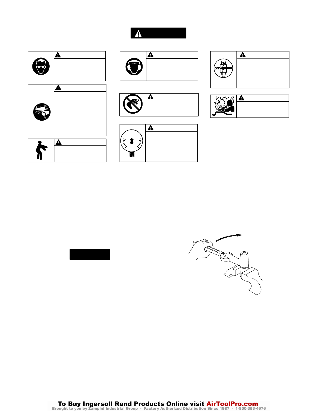
SIGNIFICATION DES ETIQUETTES D’AVERTISSEMENT
ATTENTION
LE NON RESPECT DES AVERTISSEMENTS SUIVANTS PEUT CAUSER DES BLESSURES
ATTENTION ATTENTION
Porter toujours des lunettes
de protection pendant
l’utilisation et l’entretien de
cet outil.
ATTENTION
Les outils pneumatiques
peuvent vibrer pendant
l’exploitation. Les vibrations,
les mouvements répétitifs et les
positions inconfortables
peuvent causer des douleurs
dans les mains et les bras.
N’utiliser plus d’outils en cas
d’inconfort, de picotements ou
de douleurs. Consulter un
médecin avant de recommencer
à utiliser l’outil.
90 psig
(6.2bar/620kPa)
ATTENTION
Garder une position équilibrée et
ferme. Ne pas se pencher trop
en avant pendant
l’utilisation de cet outil.
RÉGLAGES
RÉGLAGE DU COUPLE
Pour ajuster le couple sur ces clés à impulsion bi–lame,
procéder comme suit:
1. Retirer le bouchon du trou de réglage.
2. Tourner l’arbre d’entraînement jusqu’à ce que la vis de
réglage de couple soit visible dans l’ouverture.
3. A l’aide d’une clé pour six pans creux de 1,5 mm, tourner
la vis dans le sens des aiguilles d’une montre pour
augmenter le couple de serrage, ou dans le sens inverse
des aiguilles d’une montre pour réduire le couple. Ne pas
tourner le bouchon d’huile.
Porter toujours une
protection acoustique
pendant l’utilisation de cet
outil.
ATTENTION
Ne pas transporter l’outil
par son flexible.
ATTENTION
Utiliser de l’air comprimé
à une pression maximum
de 6,2 bar (620 kPa).
cuivre, côté sortie de l’arbre d’entraînement dirigé vers le
haut.
4. A l’aide d’une clé à molette, dévisser l’ensemble du corps
de moteur du couvercle du mécanisme. Ce filetage a un
pas à gauche, tourner le corps de moteur dans le sens
des aiguilles d’une montre pour le dévisser. Voir Plan
TPD1264.
SENS DES AIGUILLES D’UNE MONTRE
Couper toujours l’alimentation
d’air comprimé et débrancher le
flexible d’alimentation avant
d’installer, déposer ou ajuster
tout accessoire sur cet outil, ou
d’entreprendre une opération
d’entretien quelconque sur l’outil.
Ne pas utiliser des flexibles ou
des raccords endommagés,
effilochés ou détériorés.
POUR DESSERRER
ATTENTION
ATTENTION
NOTE
Effectuer tous les réglages finaux sur l’écrou à serrer.
4. Remonter le bouchon dans le trou de réglage.
CHANGEMENT DU FLUIDE DU MECANISME
Le fluide du mécanisme d’impulsion est changé de la façon
suivante :
1. Pour le Modèle 180PQ1 ou 280PQ1, utiliser un outil
pointu pour pousser le siège de ressort contre le ressort du
manchon de retenue. Lorsque le ressort est comprimé,
utiliser un autre outil pointu ou un tournevis à lame fine
pour déposer la bague de retenue. Retirer le siège de
ressort, le ressort et le manchon de retenue d’embout de
l’arbre d’entraînement et retirer la bille de retenue
d’embout.
2. Déposer la gaine en caoutchouc du corps.
3. Serrer soigneusement les plats du couvercle du
mécanisme dans un étau de mordaches en cuir ou en
(Plan TPD1264)
5. Retirer le moteur assemblé du couvercle du mécanisme et
extraire le mécanisme du couvercle.
6. A l’aide d’une clé pour six pans creux de 1,5 mm, tourner
la vis de réglage de couple dans le sens des aiguilles
d’une montre jusqu’à ce qu’elle vienne en butée. Tourner
la vis dans le sens inverse des aiguilles d’une montre
jusqu’à ce qu’elle vienne en butée, ou après six tours
complets.
7. Utiliser la clé en T spéciale fournie dans le nécessaire
d’outillage (Réf. No. 180PQ–99) et retirer le bouchon
d’huile et le joint du bouchon.
6
Page 7
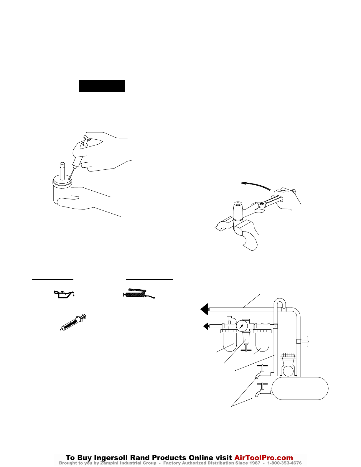
8. Tout en tenant le trou du bouchon d’huile vers le bas
au–dessus d’un récipient, tourner l’arbre d’entraînement
pour purger le fluide contenu dans le mécanisme.
9. A l’aide de la seringue et du fluide fourni dans le
nécessaire de fluide de remplacement (Réf. No.
EQ106S–K400), remplir le mécanisme avec le fluide
fourni dans le nécessaire. Voir Plan TPD1265.
NOTE
NE PAS UTILISER D’AUTRE FLUIDE. La non
utilisation du fluide de mécanisme
hydro–pneumatique fourni pourrait causer
l’endommagement de l’outil, augmenter l’entretien et
réduire les performances. N’utiliser que du fluide
propre dans ces outils.
RÉGLAGES
12. A l’aide d’une clé pour six pans creux de 1,5 mm, tourner
la vis de réglage de couple dans le sens des aiguilles
d’une montre jusqu’à ce qu’elle vienne en butée. C’est la
position de couple maximum.
13. Essuyer l’extérieur du mécanisme pour le sécher et retirer
le bouchon de la chambre d’huile. A l’aide de la seringue,
retirer 0,25 cm
et 0,3 cm
14. Remonter le bouchon de la chambre d’huile et le serrer à
un couple de 2,3 à 2,8 Nm.
15. Insérer le mécanisme, côté sortie en premier, dans le
couvercle de mécanisme serré dans les mâchoires de
l’étau.
16. Insérer l’extrémité hexagonale de l’arbre de rotor dans
l’emmanchement hexagonal à l’arrière de l’arbre
d’entraînement et visser le corps de moteur assemblé sur
le couvercle du mécanisme. Ce filetage a un pas à
gauche. Tourner le corps dans le sens inverse des aiguilles
d’une montre pour le serrer. Voir Plan TPD1266.
3
de fluide sur le modèle 180PQ1
3
sur les modèles 280P et 280PQ1.
SENS INVERSE DES AIGUILLES
D’UNE MONTRE POUR LE SERRER
(Plan TPD1265)
10. Submerger l’ouverture de remplissage dans le reste du
fluide et, à l’aide d’une clé, tourner l’arbre
d’entraînement pour purger tout l’air du système.
11. Visser le bouchon équipé du joint dans le mécanisme et le
serrer fermement.
MISE EN SERVICE DE L’OUTIL
LUBRIFICATION
Ingersoll–Rand No. 50 Ingersoll–Rand No. 67
Fluide Ingersoll–Rand
Réf. No. EQ106S–400–1
Utiliser toujours un lubrificateur avec ces outils. Nous
recommandons l’emploi du filtre–régulateur–lubrificateur
suivant :
Pour E.U. – No. C18–03–FKG0–28
Tous les 20 000 cycles, ou en fonction de l’expérience, vider
et remplir l’ensemble de mécanisme d’impulsion
conformément aux instructions du manuel en utilisant le
nécessaire de fluide de remplacement (Réf. No.
EQ106S–K400). Lubrifier l’entraîneur hexagonal et l’arbre de
sortie avant l’assemblage
VERS LE
RÉSEAU D’AIR
COMPRIMÉ
VERS
L’OUTIL
PNEU-
MATIQUE
LUBRIFICATEUR
RÉGULATEUR
LIGNE SECONDAIRE AU
MOINS 2 FOIS LA DIMEN-
SION DE L’ADMISSION
D’AIR DE L’OUTIL
.
VIDANGER
RÉGULIÈREMENT
(Plan TPD1266)
TUYAUTERIE PRINCIPALE
AU MOINS 3 FOIS LA DIMENSION DE L’ADMISSION D’AIR
DE L’OUTIL
FILTRE
COMPRESSEUR
(Plan TPD905–1)
7
Page 8

SPÉCIFICATIONS
Modèle Poignée à
levier
180PQ1 pistolet embout 1/4” 10.500 6–11 (8–15) 14–22 (19–30)
280PQ1 pistolet embout 3/8” 9.500 10–16 (14–22) 16–26 (22–35)
280P pistolet 3/8” entr.
Limiteur/
Entraînement
pouces
carré
Vitesse
libre
tr/mn
9.500 12–18 (16–24) 18–28 (24–38)
Serrage élastique Nm Serrage fort Nm
Gamme de couples
recommandée
8
Page 9
MANUAL DE USO Y MANTENIMIENTO PARA
E
TPD1511
LLAVES DE IMPULSO DE DOBLE PALETA
MODELOS 180PQ1, 280P Y 280PQ1
NOTA
Las Llaves de Impulso Modelos 180PQ1, 280P y 280PQ1 están diseñadas para operaciones de montaje
que requieran un par constante. Resultan especialmente eficaces en montaje de máquinas y aplicaciones
que requieren niveles de ruido bajos.
Ingersoll–Rand no aceptará responsabilidad alguna por la modificación de las herramientas efectuada
por el cliente para las aplicaciones que no hayan sido consultadas con Ingersoll–Rand.
AVISO
SE ADJUNTA INFORMACIÓN IMPORTANTE DE SEGURIDAD.
LEA ESTE MANUAL ANTES DE USAR LA HERRAMIENTA.
ES RESPONSABILIDAD DE LA EMPRESA ASEGURARSE DE QUE EL OPERARIO
ESTÉ AL TANTO DE LA INFORMACIÓN QUE CONTIENE ESTE MANUAL.
EL HACER CASO OMISO DE LOS AVISOS SIGUIENTES PODRÍA OCASIONAR LESIONES.
PARA PONER LA HERRAMIENTA EN
SERVICIO
S Utilice, examine y mantenga siempre esta herramienta
conforme al código de seguridad para herramientas
neumáticas portátiles de la American National
Standards Institute (ANSI B186.1).
• Para seguridad, máximo rendimiento y vida de
servicio de las piezas, use esta herramienta a una
presión de aire máxima de 90 psig (6,2 bar/620 kPa)
en la manguera de suministro de aire con diámetro
interno de 10 mm.
• Corte siempre el suministro de aire y desconecte la
manguera de suministro de aire antes de instalar,
desmontar o ajustar cualquier accesorio de esta
herramienta, o antes de realizar cualquier operación
de mantenimiento de la misma.
• No utilice mangueras de aire y accesorios dañados,
desgastados ni deteriorados.
• Asegúrese de que todas las mangueras y accesorios
sean del tamaño correcto y estén bien apretados. Vea
Esq. TPD905–1 para un típico arreglo de tuberías.
• Use siempre aire limpio y seco a una presión máxima
de 90 psig. El polvo, los gases corrosivos y/o el exceso
de humedad podrían estropear el motor de una
herramienta neumática.
• No lubrique las herramientas con líquidos inflamables
o volátiles tales como queroseno, gasoil o combustible
para motores a reacción.
• No saque ninguna etiqueta. Sustituya toda etiqueta
dañada.
USO DE LA HERRAMIENTA
• Use siempre protección ocular cuando utilice esta
herramienta o realice operaciones de mantenimiento
en la misma.
• Use siempre protección para los oídos cuando utilice
esta herramienta.
• Mantenga las manos, la ropa suelta y el cabello largo
alejados del extremo giratorio de la herramienta.
• Anticipe y esté alerta sobre los cambios repentinos en
el movimiento durante la puesta en marcha y el
manejo de toda herramienta motorizada.
• Mantenga una postura de cuerpo equilibrada y firme.
No estire demasiado los brazos al manejar la
herramienta. Pueden ocurrir reacciones de alto par a,
o a menos de, la recomendada presión de aire.
• El eje de la herramienta podría seguir girando
brevemente después de haber soltado la palanca de
estrangulación.
• Las herramientas neumáticas pueden vibrar durante
el uso. La vibración, repetición o posiciones incómodas
pueden dañarle los brazos y manos. En caso de
incomodidad, sensación de hormigueo o dolor, deje de
usar la herramienta. Consulte a un médico antes de
volver a usarla otra vez.
• Utilice únicamente los accesorios Ingersoll–Rand
recomendados.
• Utilice únicamente bocas y accesorios para llaves de
impacto. No utilice bocas o accessorios manuales
(cromados).
• Esta herramienta no ha sido diseñada para trabajar
en ambientes explosivos.
• Esta herramienta no está aislada contra descargas
eléctricas.
NOTA
El uso de piezas de recambio que no sean las auténticas piezas Ingersoll–Rand podría poner en peligro la seguridad, reducir el
rendimiento de la herramienta y aumentar los cuidados de mantenimiento necesarios, así como invalidar toda garantía.
Las reparaciones sólo serán realizadas por personal cualificado y autorizado. Consulte con el ce ntro de servicio Ingersoll–Rand
autorizado más próximo.
Toda comunicación se deberá dirigir a la oficina o al
distribuidor Ingersoll–Rand más próximo.
Ingersoll–Rand Company 2000
Impreso en EE. UU.
Page 10
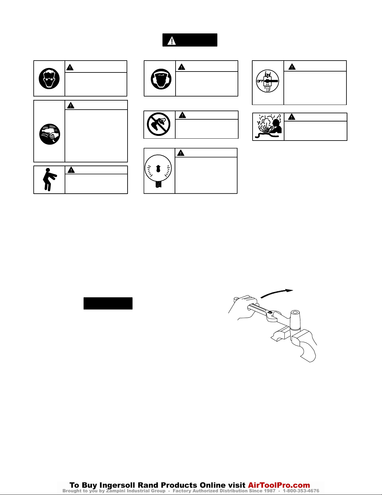
ETIQUETAS DE AVISO
AVISO
EL HACER CASO OMISO DE LOS AVISOS SIGUIENTES PODRÍA OCASIONAR LESIONES.
ADVERTENCIA
Use siempre protección ocular
cuando utilice esta herramienta
o realice operaciones de
mantenimiento en la misma.
ADVERTENCIA
Las herramientas neumáticas
pueden vibrar durante el uso.
La vibración, los movimientos
repetitivos o las posiciones
incómodas podrían dañarle los
brazos y las manos. En caso
de incomodidad, sensación de
hormigueo o dolor, dejar de
usar la herramienta. Consultar
al médico antes de volver a utilizarla.
90 psig
(6.2bar/620kPa)
ADVERTENCIA
Mantener una postura del cuerpo
equilibrada y firme. No estirar demasiado los brazos al manejar la
herramienta.
AJUSTE DE PAR
Para ajustar el par de estas Llaves de Impulso de Doble
Paleta, proceda como sigue:
1. Saque el Tapón de Orificio de Ajuste.
2. Gire el Eje de Accionamiento hasta que el tornillo de
ajuste de par sea visible a través de dicho orificio.
3. Con una llave hexagonal de 1,5 mm, gire el Tornillo de
Ajuste de Par a la derecha para incrementar el par y a la
izquierda para disminuirlo. No gire el Tapón de Aceite.
ADVERTENCIA
Use siempre protección para
los oídos cuando utilice esta
herramienta.
ADVERTENCIA
No coger la herramienta
por la manguera para levantarla.
ADVERTENCIA
Manejar la herramienta a una
presión de aire máxima de 90
psig (6,2 bar/620 kPa).
AJUSTES
cubiertas de cobre o cuero con el extremo de salida del
eje de accionamiento hacia abajo.
4. Utilizando una llave ajustable, desatornille el conjunto de
carcasa de motor de la cubierta de mecanismo. Puesto
que se trata de una rosca hacia la izquierda, gire la
carcasa de motor en el sentido de las agujas del reloj
para quitarla. Vea Esq. TPD1264
ADVERTENCIA
Cortar siempre el suministro
de aire y desconectar la manguera de suministro de aire
antes de instalar, retirar o ajustar cualquier accesorio de esta
herramienta, o antes de realizar
cualquier operación de mantenimiento de la misma.
ADVERTENCIA
No utilizar mangueras de aire
y accesorios dañados, desgastados ni deteriorados.
SENTIDO DE LAS AGUJAS
DEL RELOJ PARA DESATAR
NOTA
Haga todos los ajustes finales trabajando.
4. Vuelva a poner en su sitio el Tapón de Orificio de Ajuste.
CAMBIO DE FLUIDO DE MECANISMO
Para cambiar el fluido de mecanismo del mecanismo de
impulso, proceda como sigue:
1. Para los Modelos 180PQ1 o 280PQ1, utilizar una varilla
puntiaguda para empujar el asiento de muelle contra el
muelle de manga retenedora. Mientras el muelle está
comprimido, use otra varilla puntiaguda o destornillador
de hoja fina para sacar el Aro Retenedor. Saque el asiento
de muelle, muelle y manga retenedora de broca fuera del
eje de accionamiento y saque la bola retenedora de broca.
2. Saque la funda de carcasa de caucho.
3. Sujete con cuidado los lados planos de la cubierta de
mecanismo en un tornillo de banco con mordazas
(Esq. TPD1264)
5. Levante el motor ensamblado y sáquelo de la carcasa de
mecanismo y saque el conjunto de mecanismo fuera de la
cubierta.
6. Con una llave hexagonal de 1,5 mm, gire el Tornillo de
Ajuste de Par a la derecha hasta que se pare. Gire el
tornillo a la izquierda hasta que se pare o dé seis vueltas
completas.
7. Utilizando la llave en T especial suministrada con la caja
de herramientas (Pieza Nº 180PQ–99), saque el tapón de
aceite y el retén de dicho tapón de aceite.
10
Page 11
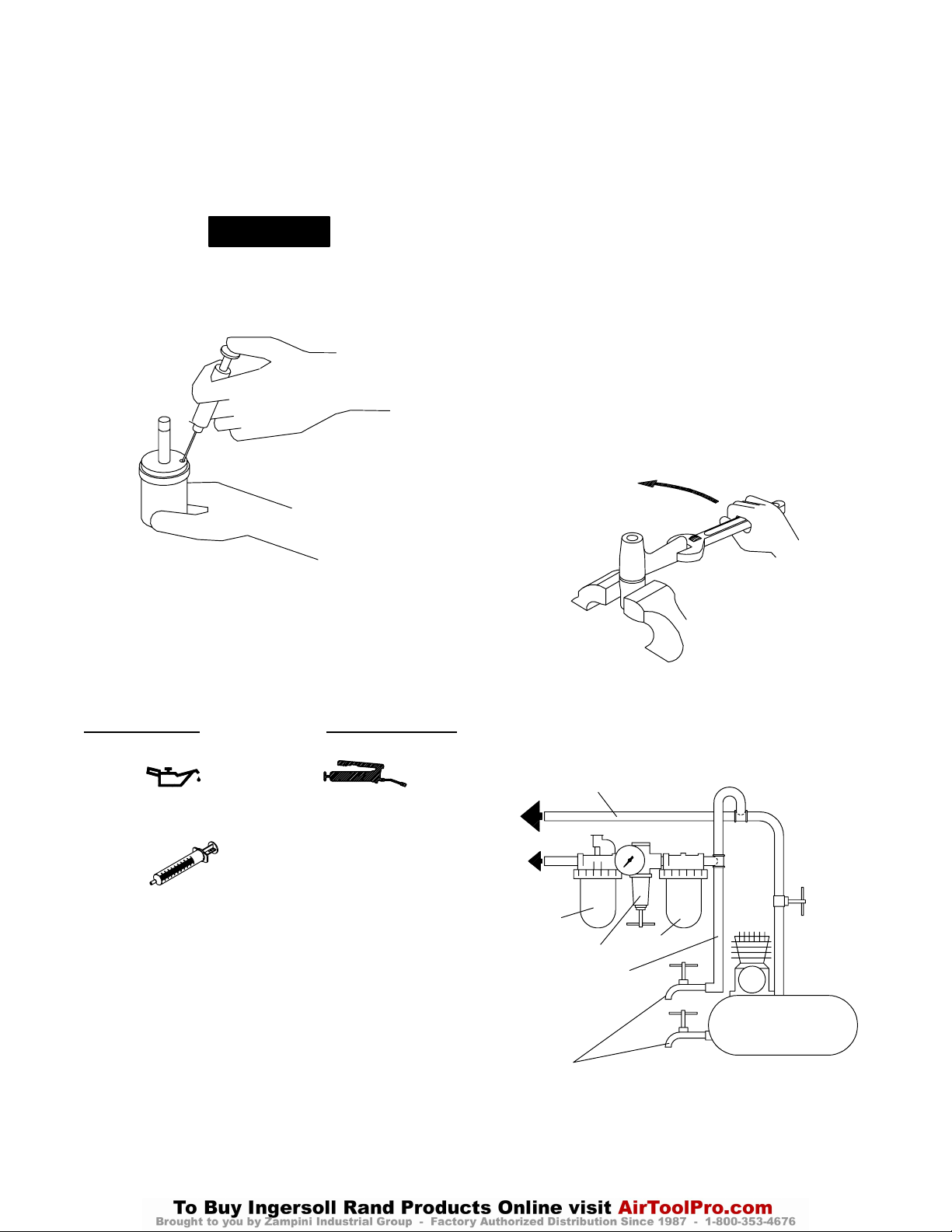
AJUSTES
8. Con el orificio de tapón de aceite hacia abajo sobre un
contenedor, gire el eje de accionamiento para purgar el
líquido del mecanismo.
9. Con la jeringuilla y el fluido del equipo de cambio de
fluido (Pieza Nº. EQ106S–K400, llene el mecanismo con
el fluído suministrado en dicho equipo. Vea Esq.
TPD1265.
NOTA
NO SUSTITUYA NINGÚN OTRO FLUIDO. Si no se
usa el fluido suministrado, se podría dañar la
herramienta, incrementar su mantenimiento y
disminuir su rendimiento. Use solamente fluido limpio
en estas herramientas.
12. Con una llave hexagonal de 1,5 mm, gire el Tornillo de
Ajuste de Par a la derecha hasta que se pare. Ésta es la
posición de máximo par.
13. Limpie la parte de fuera del mecanismo y séquelo, y
saque el tapón de la cámara de aceite. Utilizando la
jeringuilla, saque 0,25 cc de fluido de los modelos
180PQ1 y 0,3 cc de los modelos 280P y 280PQ1.
14. Instale el Tapón de Cámara de Aceite y apriételo entre
20 y 25 pulg.–lb (2,3 a 2,8 Nm) de par.
15. Inserte el conjunto de mecanismo, con el extremo de
salida primero, en la cubierta del mecanismo fijado en un
tornillo de banco.
16. Inserte el extremo hexagonal del eje rotor en el hueco
hexagonal de la parte trasera del eje de accionamiento, y
enrosque la carcasa de motor ensamblado en la cubierta
de mecanismo. Ésta es una rosca hacia la izquierda.
Gire la carcasa en el sentido opuesto al de las agujas del
reloj para apretarla. Vea Esq. TPD1266.
SENTIDO OPUESTO AL DE LAS AGUJAS
DEL RELOJ PARA APRETAR
(Esq. TPD1265)
10. Sumerja el orificio de llenado en el resto del fluido y,
utilizando una llave, gire el eje de accionamiento para
purgar el aire que pudiera quedar en el sistema.
11. Enrosque el Tapón de Aceite con el retén del tapón de
aceite en el mecanismo hasta que quede bien ajustado.
PARA PONER LA HERRAMIENTA EN SERVICIO
LUBRICACIÓN
Ingersoll–Rand Nº 50 Ingersoll–Rand Nº 67
Pieza de fluido
Ingersoll–Rand
Nº. EQ106S–400–1
Utilice siempre un lubricador de aire comprimido con estas
herramientas. Recomendamos la siguiente unidad de
Filtro–Lubricador–Regulador:
Para EE.UU. – Nº. C18–03–FKG0–28
Después de cada 20 000 ciclos, o como indique la
experiencia, drene y vuelva a llenar el Conjunto de
Accionamiento de Unidad de Impulso tal y como se indica en
este manual, usando el equipo de cambio de fluido (Pieza
Nº EQ106S–K400). Lubrique el eje de salida y accionamiento
hexagonal antes del montaje.
TUBERÍAS PRINCIPALES 3
VECES EL TAMAÑO DE
ENTRADA DE HERRAMIENTA
AL SISTEMA
NEUMÁTICO
A LA
HERRA–
MIENTA
NEUMÁTICA
LUBRICADOR
TUBERÍA DE RAMAL
2 VECES EL TAMAÑO
DE ENTRADA DE
HERRAMIENTA
NEUMÁTICA
PURGAR
PERIÓDICAMENTE
NEUMÁTICA
REGULADOR
(Esq. TPD1266)
FILTRO
COMPRESOR
(Esq. TPD905–1)
11
Page 12

ESPECIFICACIONES
Modelo Tipo de
Empuñadura
Portabroca/Accio-
namiento
pulg. rpm Retroceso Suave
180PQ1 pistola 1/4 pulg.
broca de
inserción
280PQ1 pistola 3/8 pulg.
broca de
inserción
280P pistola cuadradillo de 3/8
pulg.
Velocidad
Libre
Gama de par
recomendada
Golpe Fuerte
ft–lbs (Nm)
ft–lbs (Nm)
10.500 6–11 (8–15) 14–22 (19–30)
9.500 10–16 (14–22) 16–26 (22–35)
9.500 12–18 (16–24) 18–28 (24–38)
12
Page 13
MANUAL DE FUNCIONAMENTO E MANUTENÇÃO
P
TPD1511
PARA FERRAMENTAS PNEUMÁTICAS DE
IMPULSO DE LÂMINAS
DUPLAS MODELOS 180PQ1, 280P E 280PQ1
AVISO
As Ferramentas Pneumáticas de Impulso Modelos 180PQ1, 280P e 280PQ1 são concebidas para
uso em operações de montagem que necessitem torque consistente. Elas são adequadas
idealmente para montagens de equipamento e aplicações que exijam níveis baixos de ruído.
A Ingersoll–Rand não é responsável por modificações feitas pelo cliente em ferramentas nas quais a
Ingersoll–Rand não tenha sido consultada.
ADVERTÊNCIA
INFORMAÇÃO DE SEGURANÇA IMPORTANTE EM ANEXO.
LEIA ESTE MANUAL ANTES DE OPERAR A FERRAMENTA.
É DA RESPONSABILIDADE DO EMPREGADOR COLOCAR A INFORMAÇÃO
DESTE MANUAL NAS MÃOS DO OPERADOR.
O NÃO CUMPRIMENTO DAS SEGUINTES ADVERTÊNCIAS PODE RESULTAR EM FERIMENTOS.
COLOCANDO A FERRAMENTA
EM FUNCIONAMENTO
S Sempre opere, inspeccione e mantenha esta
ferramenta de acordo com o Código de Segurança do
Instituto Americano de Padrões Nacionais para
Ferramentas Pneumáticas Portáteis (ANSI B186.1).
• Para segurança, máximo desempenho e máxima
durabilidade das peças, opere esta ferramenta com uma
pressão de ar máxima de 6,2 ba r/6 2 0 kPa (9 0 psig) na
entrada da mangueira de alimentação de ar com
diâmetro interno de 10 mm (3/8 ”).
• Desligue sempre a alimentação de ar e desconecte a
mangueira de alimentação de ar antes de instala r,
remover ou ajusta r qualquer acess ório nesta ferramenta,
ou antes de executar qualquer serv i ço de manutenção
nesta ferramenta.
• Não use mangueiras de ar ou adaptadores da nifica do s,
gastos ou deteriorados.
• Certifique–se de que todas as mangueiras e adaptadores
sejam do tamanho co rrecto e estejam apertados com
firmeza. Veja o Desenho TPD905–1 para um arranjo
típico de tubagem.
• Use sempre ar seco e limpo co m pressão máxima de
90 psig. Pó, fumos corrosivos e/ou humidade excessiva
podem arruinar o motor de uma ferramenta pneumática.
• Não lubrifique as ferramentas com líquidos inflamáveis
ou voláteis tais como querosene, diesel ou combustível de
jactos.
• Não remova nenhum rótulo. Reponha qualquer rótulo
danificado.
USANDO A FERRAMENTA
• Use sempre óculos de protecção qua ndo estiver opera ndo
ou executando serviço de manutenção nesta ferramenta.
• Use sempre protecção contra ruído ao operar esta
ferramenta.
• Mantenha as mãos, partes do vestuário soltas e cabelos
compridos afasta dos da extremidade em rotação.
• Antecipe e esteja alerta a mudanças repentinas no
movimento quando ligar e operar qualquer ferramenta
motorizada.
• Mantenha a posição do corpo equilibrada e firme. Não
exagere quando operar esta ferramenta. Torques de
reacção elevados po dem ocorrer na ou abaixo da pressão
de ar recomendada.
• O eixo da ferramenta pode continuar a girar
brevemente após a pressão ter sido aliviada.
• Ferramentas accionada s pneumáticamente podem vibrar
em uso. Vibração, movimentos repetitivos ou posições
desconfortáveis podem ser prejudiciais às mãos e aos
braços. Pare de usar a ferramenta caso ocorra algum
desconforto, sensação de formigueiro ou dor. Procure
assistência médica antes de retornar ao trabalho.
• Use acessórios recomendados pela Ingersoll–Rand.
• Use somente soquetes e acessórios de impacto. Não use
soquetes ou acessórios de mão (cromo).
• Esta Ferramenta não foi co ncebida para trabalhos em
atmosferas explosivas.
• Esta Ferramenta não está isolada contra choques
eléctricos.
AVISO
O uso de peças de substituição que não sejam genuinamente da Ingersoll–Rand podem resultar em riscos de segurança,
diminuição do desempenho da ferramenta, aumento da necessidade de manutenção e pode invalidar todas as garantias.
As reparações devem ser feitas somente por pessoal treinado autorizado. Consulte o Centro de Serviços da Ingersoll–Rand mais
próximo.
Envie Todos os Comunicados Para o Distribuidor ou
Escritório da Ingersoll–Rand Mais Próximo.
Ingersoll–Rand Company 2000
Impresso nos E.U.A.
Page 14
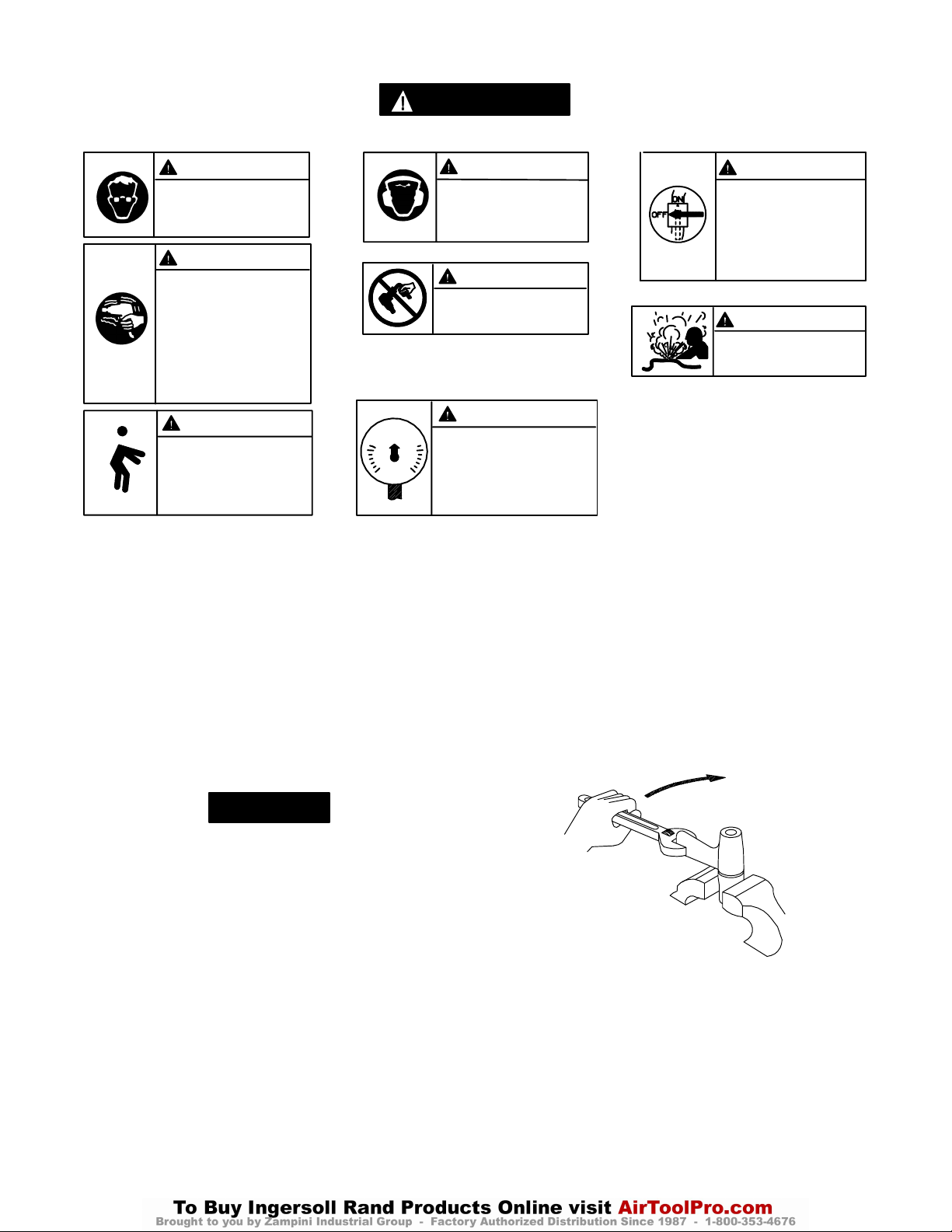
IDENTIFICAÇÃO DO RÓTULO DE ADVERTÊNCIA
ADVERTÊNCIA
O NÃO CUMPRIMENTO DAS SEGUINTES ADVERTÊNCIAS PODE RESULTAR EM FERIMENTOS.
ADVERTÊNCIA
Use sempre óculos de
protecção quando estiver
operando ou executando algum
serviço de manutenção nesta
ferramenta.
ADVERTÊNCIA
Ferramentas accionadas
pneumáticamente podem vibrar
em uso. Vibração, movimentos
repetitivos ou posições
desconfortáveis podem ser
prejudiciais às mãos e aos
braços. Pare de usar a
ferramenta caso ocorra algum
desconforto, sensação de
formigueiro ou dor. Procure
assistência médica antes de
retornar ao trabalho.
ADVERTÊNCIA
Mantenha a posição do corpo
equilibrada e firme. Não
exagere quando operar esta
ferramenta. Torques de reacção
elevados podem ocorrer sob a
pressão de ar recomendada.
90 psig
(6.2bar/620kPa)
AJUSTES
AJUSTE DE TORQUE
Para ajustar o torque nestas Chaves Dinamométricas de
Impulsão de Lâminas Duplas, proceda da seguinte maneira:
1. Remova o Bujão do Furo de Ajuste.
2. Gire o Eixo de Comando até o Parafuso de Ajuste de
Torque estar visível na abertura.
3. Usando uma chave Allen de 1,5 mm, gire o Parafuso de
Ajuste no sentido horário para aumentar o torque de saída
e no sentido contrário aos do ponteiros do relógio para
diminuir o torque de saída. Não gire o Bujão de Óleo.
ADVERTÊNCIA
Use sempre protecção contra o
ruído ao operar esta ferramenta.
ADVERTÊNCIA
Não carregue a ferramenta
segurando na mangueira.
ADVERTÊNCIA
Opere com pressão do ar Máxima
de 90–100 psig (6,2–6,9 bar).
2. Remova o Calço do Corpo de Borracha.
3. Usando mordentes de morsa de cobre, agarre com
cuidado as pás da Capa do Mecanismo com a
extremidade de saída do Eixo de Comando para baixo.
4. Usando uma chave ajustável, desparafuse o Conjunto do
Corpo do Motor da Cobertura do Mecanismo. Esta é uma
rosca à esquerda, gire o Corpo do Motor no sentido
horário para removê–lo.
Veja o Desenho TPD1264.
SENTIDO HORÁRIO PARA SOLTAR
ADVERTÊNCIA
Desligue sempre a alimentação
de ar e desconecte a mangueira
de alimentação de ar antes de
instalar, remover ou ajustar
qualquer acessório nesta
ferramenta, ou antes de
executar algum serviço de
manutenção nesta ferramenta.
ADVERTÊNCIA
Não use mangueiras de ar ou
adaptadores danificados,
gastos ou deteriorados.
AVISO
Faça todos os ajustes finais no serviço.
4. Reponha o Bujão do Furo de Ajuste.
MUDANDO O FLUIDO DO MECANISMO
Para mudar o Fluido do Mecanismo no Mecanismo de
Impulso, proceda da seguinte maneira:
1. Para o modelo 180PQ1 ou 280PQ1, use uma ponta de
prova para empurrar o Assento da Mola contra a Mola da
Camisa Retentora. Enquanto a Mola for comprimida
utilize uma outra ponta de prova ou chave de fenda de
lâmina fina para remover o Anel de Retenção. Erga o
Assento da Mola, a Mola e a Camisa de Retenção do bite
para fora do Eixo de Comando e remova a Esfera de
Retenção do Bite.
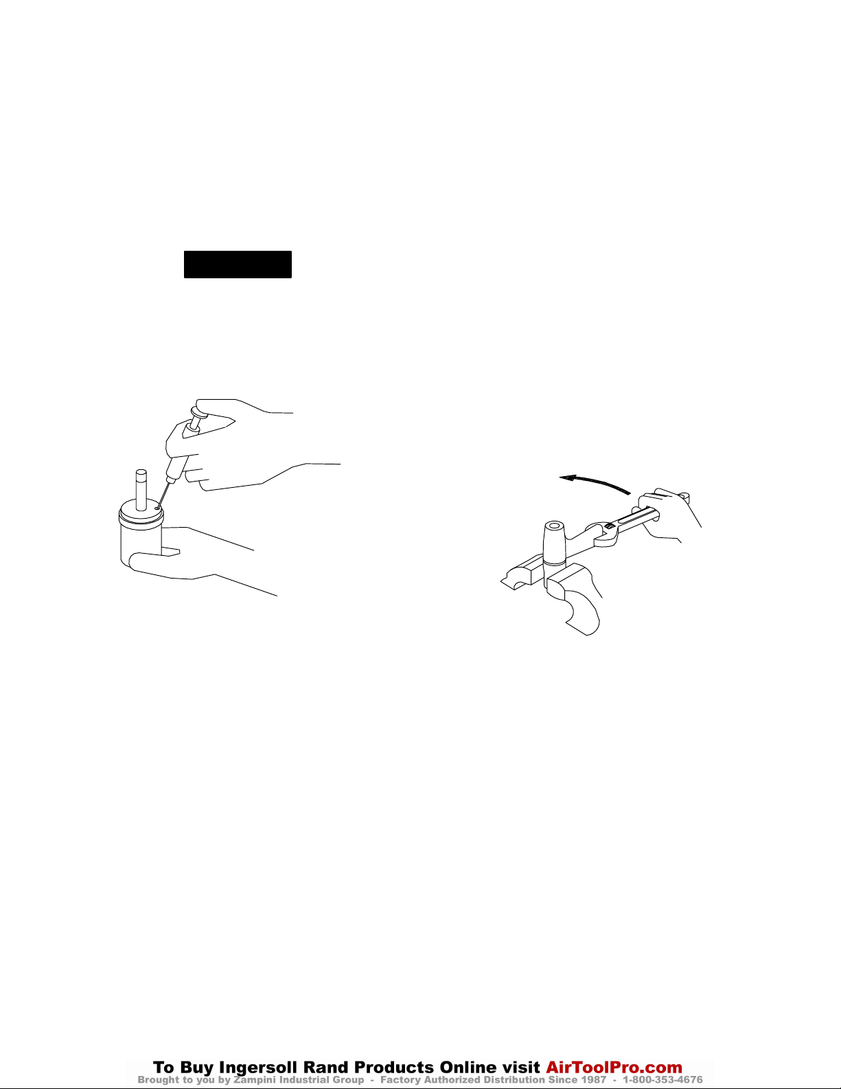
(Desenho TPD1264)
5. Erga para fora o motor montado da Cobertura do
Mecanismo e puxe o conjunto do mecanismo para fora da
capa.
6. Usando uma chave Allen de 1,5 mm, gire o Parafuso de
Ajuste de Torque no sentido horário até o Parafuso parar.
Gire o Parafuso no sentido contrário ao dos ponteiros do
rolócio até que ele pare ou execute seis voltas completas.
14
Page 15
AJUSTES
7. Usando uma Chave em T (Tee) fornecida no Kit da
Ferramenta, (Número de Pedido 180PQ–99), remova o
Bujão de Óleo e o Lacre do Bujão de Óleo.
8. Com a abertura do bujão de óleo para baixo sobre um
recipiente, gire o Eixo de Comando para expelir o fluido
do mecanismo.
9. Usando uma seringa e fluido do Kit de Reposição de
Fluído (Número de Pediddo EQ106S–K400), encha o
mecanismo com fluido fornecido no Kit.
Veja Desenho TPD1265.
AVISO
NÃO SUBSTITUA POR QUALQUER OUTRO
FLUIDO.
Caso o fluido fornecido não for usado danos podem
ocorrer à ferramenta, aumento da manutenção e
diminuição do desempenho. Use somente fluido limpo
nestas ferramentas.
11. Rosqueie o Bujão de Óleo com o Lacre do Bujão de Óleo
no mecanismo até que ele esteja apertado.
12. Usando uma chave Allen de 1,5 mm, gire o Parafuso de
Ajuste de Torque no sentido horário até o Parafuso parar.
Esta é a posição de máximo torque.
13. Limpe a parte externa do mecanismo a seco e limpe e
remova o Bujão da Câmara de Óleo. Usando uma seringa,
retire 0,25 cc de fluído dos modelos 180PQ1 e 0,3 cc dos
modelos 280P e 280PQ1.
14. Instale o Bujão da Câmara de Óleo e aperte–o com um
torque de 2,3 a 2,8 Nm (20 a 25 pol–lb).
15. Insira o conjunto do mecanismo, com a extremidade de
saída liderando, na Capa do Mecanismo grampeada nas
garras da morsa.
16. Insira a extremidade hexagonal do eixo do rotor no
recesso na traseira do Eixo de Comando e rosqueie o
Corpo do Motor montado na Capa do Mecanismo. Esta é
uma rosca à esquerda. Gire o Corpo no sentido
contrário ao do dos ponteiros do relógio para apertá–lo.
Veja Desenho TPD1266.
SENTIDO CONTRÁRIO AO DOS
PONTEIROS DO RELÓGIO PARA APERTAR
(Desenho TPD1265)
10. A abertura de enchimento deve ser submersa no restante
do fluído, e usando uma chave, gire o Eixo do Comando
para expelir qualquer ar remanescente do sistema.
(Desenho TPD1266)
15
Page 16
COLOCANDO A FERRAMENTA EM FUNCIONAMENTO
LUBRIFICAÇÃO
Ingersoll–Rand No. 50 Ingersoll–Rand No. 67
Fluído Ingersoll–Rand
Número de Pedido
EQ106S–400–1
Use sempre um lubrificador de ar de linha com estas
ferramentas. Nós recomendamos a seguinte Unidade
Filtro–Lubrificador–Regulador:
Para E.U.A. – No. C18–03–FKG0–28
Depois de cada 20 000 ciclos, ou como a experiência indicar,
drene e encha o Conjunto do Comando da Unidade de Impulso
como instruído neste manual usando o Kit de Reposição de
Fluído (Número de Pedido EQ106S–K400). Lubrifique o
comando hexagonal e o eixo de saída antes de montar.
ESPECIFICAÇÕES
Modelo Tipo de
Punho
Encabadouro/Coman-doVelocidade Livre Intervalo de Torque
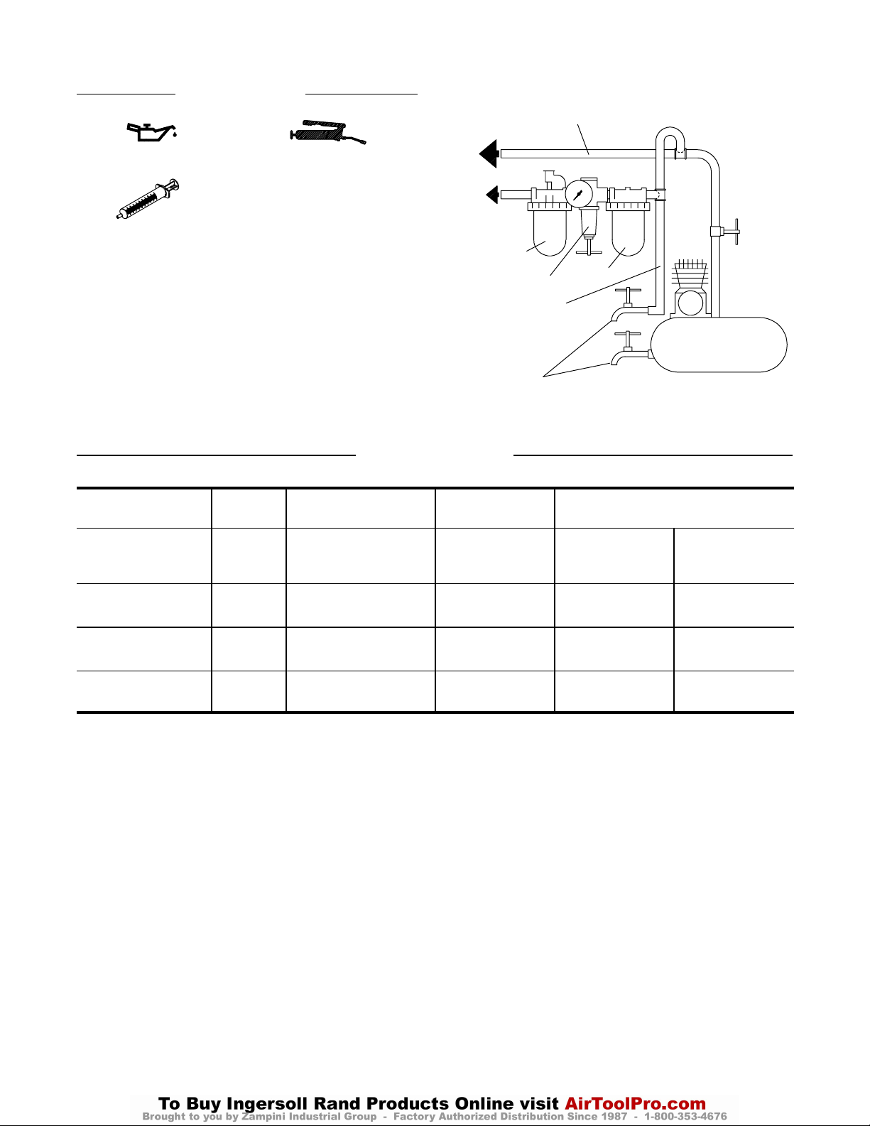
LINHAS PRINCIPAIS 3 VEZES O TAMANHO DA
PARA
SISTEMA DE AR
PARA
FERRAMENTA
PNEUMÁTICA
LUBRIFICADOR
LINHA RAMIFICADA
2 VEZES O TAMANHO
DA ENTRADA DA
FERRAMENTA
PNEUMÁTICA
ENTRADA DA FERRAMENTA PNEUMÁTICA
REGULADOR
DRENE
REGULARMENTE
FILTRO
COMPRESSOR
(Desenho TPD905–1)
Recomendado
pol. rpm Aperto
180PQ1 pistola 1/4”
bite de inserção
280PQ1 pistola 3/8”
bite de inserção
280P pistola 3/8”
quadrada
Batimento Duro
Ligeiro
Nm (pés–lb)
Nm (pés–lb)
10.500 8–15 (6–11) 19–30 (14–22)
9.500 14–22 (10–16) 22–35 (16–26)
9.500 16–24 (12–18) 24–38 (18–28)
16
Page 17
17
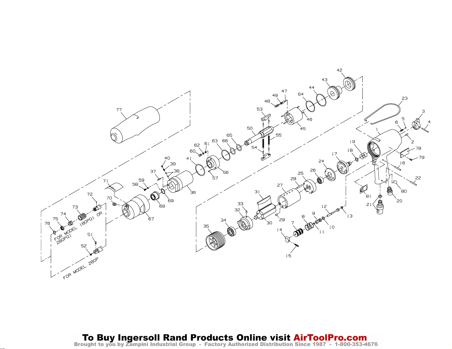
(Dwg. TPA1329)
Page 18
18
PART NUMBER FOR ORDERING PART NUMBER FOR ORDERING
Motor Housing Assembly 21 Exhaust Deflector Assembly . . . . . . . . . . . . . 180PQ–A23
for model 180PQ1 . . . . . . . . . . . . . 180PQ–A40 22 Deflector Retaining Pin . . . . . . . . . . . . . . . . . EQ106P–152
for model 280P or 280PQ1 . . . . . . 280PQ–A40 23 Suspension Bail . . . . . . . . . . . . . . . . . . . . . . . EQ106S–365
1 Motor Housing 24 Rear End Plate Spacer . . . . . . . . . . . . . . . . . . 180PQ–43
for model 180PQ1 . . . . . . . . . . . . . 180PQ–40 Rear End Plate Assembly . . . . . . . . . . . . . . . . 180PQ–A12
for model 280P or 280PQ1 . . . . . . 280PQ–40 25 Rear End Plate . . . . . . . . . . . . . . . . . . . . . 180PQ–12
2 Reverse Lever Alignment Pin . . . . . . . . . EQ104S–299 + 26 Rear Rotor Bearing . . . . . . . . . . . . . . . . . 500A–22
3 Reverse Lever . . . . . . . . . . . . . . . . . . . . . 180PQ–328 27 Cylinder Assembly
4 Reverse Lever Pin . . . . . . . . . . . . . . . . . . 380PQ–298 for model 180PQ1 . . . . . . . . . . . . . 180PQ–A3
5 Reverse Lever Detent Ball EQ104S–333 for model 280P or 280PQ1 . . . . . . 280PQ–A3
6 Reverse Lever Detent Spring . . . . . . . . . . 180PQ–566 28 Rear End Plate Alignment Pin . . . . . . . . . 180PQ–152
7 Throttle Bushing Assembly . . . . . . . . . . . EQ106P–A503 29 Front End Plate Alignment Pin . . . . . . . . 2400P–152
8 Throttle Bushing Seal (3) . . . . . . . . EQ106P–283 30 Rotor
9 Throttle Valve Assembly . . . . . . . . . . . . . EQ106P–A304 for model 180PQ1 . . . . . . . . . . . . . 180PQ–53
10 Throttle Valve Seal . . . . . . . . . . . . . EQ106S–159 for model 280P or 280PQ1 . . . . . . 280PQ–52
11 Valve Retaining Ring . . . . . . . . . . . . . . . . EQ106P–303 + 31 Vane Packet (set of 5 Vanes)
12 Throttle Rod Assembly . . . . . . . . . . . . . . EQ106P–A302 for model 180PQ1 . . . . . . . . . . . . . 180PQ–42–5
13 Throttle Rod Seal . . . . . . . . . . . . . . EQ106P–288 for model 280P or 280PQ1 . . . . . . 280PQ–42–5
14 Trigger . . . . . . . . . . . . . . . . . . . . . . . . . . . EQ106P–93 Front End Plate Assembly 180PQ–A11
15 Trigger Pin . . . . . . . . . . . . . . . . . . . . . . . . EQ106P–265 32 Front End Plate . . . . . . . . . . . . . . . . . . . . . 180PQ–11
16 Throttle Retaining Pin . . . . . . . . . . . . . . . 180PQ–120 33 Alignment Pin . . . . . . . . . . . . . . . . . . . . . 380SQ–298
17 Reverse Valve Assembly . . . . . . . . . . . . . 180PQ–A329 + 34 Front End Plate Bearing . . . . . . . . . . . . . . 500P–22
18 Reverse Valve Assembly . . . . . . . . 180PQ–67 35 Front End Plate Spacer . . . . . . . . . . . . . . . . . . 180PQ–41
19 Reverse Valve Spring . . . . . . . . . . . . . . . . 180PQ–567
20 Inlet Bushing . . . . . . . . . . . . . . . . . . . . . . EQ106S–565
+ Indicates Motor Tune–up Kit part.
Page 19
19
PART NUMBER FOR ORDERING PART NUMBER FOR ORDERING
Impulse Unit Drive Assembly 53 Blade Assembly (2)
for model 180PQ1 . . . . . . . . . 180PQ–A200 for model 180PQ1 . . . . . . . . . . . . 180PQ–A627
for model 280P . . . . . . . . . . . . 280P–A200 for model 280P or
for model 280PQ1 . . . . . . . . . 280PQ–A200 280PQ1 . . . . . . . . . . . . . . . . . . . . . 280PQ–A627
36 Housing Assembly 54 Blade Assembly Pin
for model 180PQ1 . . . . . . . . . 180PQ–A31 (2 per assembly) . . . . . . . . . . . . . . . . . –––
for model 280P or 280PQ1 . . . 280PQ–A31 55 Blade Spring (2) . . . . . . . . . . . . . . . . . . . . 180PQ–568
37 Torque Adjustment Screw . . . . . . . . . 180PQ–230 56 Front Liner Cover Assembly . . . . . . . . . . 180PQ–A211
38 Adjustment Screw Plug Lock (2) . . . . 180PQ–283 57 Liner Cover Pin . . . . . . . . . . . . . . . . . 180PQ–232
39 Plug Lock Spring . . . . . . . . . . . . . . . . 180PQ–219 58 Oil Plug . . . . . . . . . . . . . . . . . . . . . . . . . . 180PQ–277
40 Plug Lock Screw . . . . . . . . . . . . . . . . 500A–230 59 Oil Plug Seal . . . . . . . . . . . . . . . . . . . . . . EQ110P–288
41 Liner O–ring . . . . . . . . . . . . . . . . . . . . 180PQ–236 60 Oil Stop Cap Assembly . . . . . . . . . . . . . . 180PQ–A38
42 Housing Cap . . . . . . . . . . . . . . . . . . . . . . . 180PQ–207 61 Stop Cap O–ring . . . . . . . . . . . . . . . . . EQ106S–288
43 Rear Liner Cover Assembly . . . . . . . . . . . 180PQ–A212 62 Back–up Ring . . . . . . . . . . . . . . . . . . . 380SQ–272
44 Liner Cover O–ring . . . . . . . . . . . . . . 180PQ–273 63 Front Liner Seal . . . . . . . . . . . . . . . . . . . . EQ104S–236
45 Liner Assembly 64 Rear Liner Seal . . . . . . . . . . . . . . . . . . . . . 180PQ–273
for model 180PQ1 . . . . . . . . . 180PQ–A203A 65 Drive Shaft Seal . . . . . . . . . . . . . . . . . . . . 180PQ–271
for model 280P or 280PQ1 . . . 280PQ–A203A 66 Seal Back–up Ring . . . . . . . . . . . . . . . . . . 380PQ–272
46 Liner Pin (4) . . . . . . . . . . . . . . . . . . . . 180PQ–298 Mechanism Cover Assembly
47 Relief Valve . . . . . . . . . . . . . . . . . . . . . . . 180PQ–298 for model 180PQ1 . . . . . . . . . . . . 180PQ–A727
for model 180PQ1 . . . . . . . . . 180PQ–222 for model 280P or 280PQ1 . . . . . . 280PQ–727
for model 280P or 280PQ1 . . . 280PQ–222 67 Mechanism Cover
48 Spring Guide Assembly for model 180PQ1 . . . . . . . . . . . . 180PQ–727
for model 180PQ1 . . . . . . . . . 180PQ–A255 for model 280P or 280PQ1 . . . . . . 280PQ–727
for model 280P or 280PQ1 . . . 280PQ–A255 68 Cover Bushing . . . . . . . . . . . . . . . . . . 180PQ–641
49 Spring Guide Seal . . . . . . . . . . . . . . . . 180PQ–272 69 Bushing Spacer . . . . . . . . . . . . . . . . . 180PQ–229
50 Drive Shaft 70 Adjustment Hole Plug . . . . . . . . . . . . 180PQ–95
for model 180PQ1 . . . . . . . . . 180PQ–626A 71 Warning Label
for model 280PQ1 . . . . . . . . . 280PQ–626C for models ending in –EU . . . . . . EU–99
50 Drive Shaft Assembly (for for all other models . . . . . . . . . . . . WARNING–2–99
model 280P) . . . . . . . . . . . . . . . . . . . . . . . 280P–A626A
51 Socket Retaining Pin . . . . . . . . . . . . . 5020–716
52 Retaining Pin Spring . . . . . . . . . . . . . 401–718
Page 20
20
PART NUMBER FOR ORDERING PART NUMBER FOR ORDERING
Bit Chuck Assembly (for model * Mechanism Tune–up Kit (includes
180PQ1 or 280PQ1) . . . . . . . . . . . . . . . . . . . . . . 180PQ–A667 illustrated items 39, 41, 44, 49, 51, 52, 55, 59, 61,
72 Bit Retaining Ball . . . . . . . . . . . . . . . . . . . . . EQ104S–929 62, 63, 64, 65, 66 and 69) . . . . . . . . . . . . . . . . . . . 180PQ–K600A
73 Bit Retaining Sleeve . . . . . . . . . . . . . . . . . . . EQ104S–930 * Fluid Replacement Kit (includes Fluid
74 Retaining Sleeve Spring . . . . . . . . . . . . . . . . EQ104S–931 Syringe, Fill Tube and 4 oz. [31mL] of
75 Spring Seat . . . . . . . . . . . . . . . . . . . . . . . . . . EQ104S–932 Replacement Fluid) . . . . . . . . . . . . . . . . . . . . . . . . EQ106S–K400
76 Retaining Ring . . . . . . . . . . . . . . . . . . . . . . . EQ104S–933 * Replacement Fluid (4 oz.) EQ106S–400–1
77 Rubber Housing Boot * Tool Kit (includes all the specialized
for model 180PQ1 . . . . . . . . . . . 180PQ–2 tooling required to repair these tools
for model 280P or 280PQ1 . . . . . 280PQ–2 and consists of two Spanner Plugs a
78 Nameplate Tee Wrench with a special tip, an
for model 180PQ1 . . . . . . . . . . . 180PQ–301 O–ring Installer Fixture and a pressing
for model 280P . . . . . . . . . . . . . . 280P–301 fixture that has a Disassembly Arbor
for model 280PQ1 . . . . . . . . . . . 280PQ–301 and Pressing Sleeve.) . . . . . . . . . . . . . . . . . . . . . . . 180PQ–99
for all models ending in –EU . . . 280P–EU–301 * Square Drive Anvil (for model
79 Nameplate Driver Screw (for 180PQ1) . . . . . . . . . . . . . . . . . . . . . . . . . . . . . . . . . 180P–626
model 280P) (2) . . . . . . . . . . . . . . . . . . . . . . . . . EQ106S–322 * Drive Shaft/Liner Replacement Kit
80 Oil Daily Label . . . . . . . . . . . . . . . . . . . . . . . . . . 500P–69 (includes illustrated items 45 and 50)
81 Two Speed Throttle Label . . . . . . . . . . . . . . . . . 180PQ–68 for model 180PQ1 . . . . . . . . . . . . . 180PQ–K203
* Motor Tune–up Kit (includes for model 280PQ1 . . . . . . . . . . . . . 280PQ–K203
illustrated items, 26, 31 and 34) for model 280P . . . . . . . . . . . . . . . . 280P–K203
for model 180PQ1 . . . . . . . . . . . 180PQ–K500
for model 280P or 280PQ1 . . . . . 280PQ–K500
* Not illustrated.
Page 21
MAINTENANCE SECTION
Always wear eye protection when operating or
performing maintenance on this tool.
Always turn off the air supply and disconnect the air
supply hose before installing, removing or adjusting
any accessory on this tool or before performing any
maintenance on this tool.
CHANGING THE MECHANISM FLUID
To change the Mechanism Fluid in the Impulse Mechanism, proceed as follows:
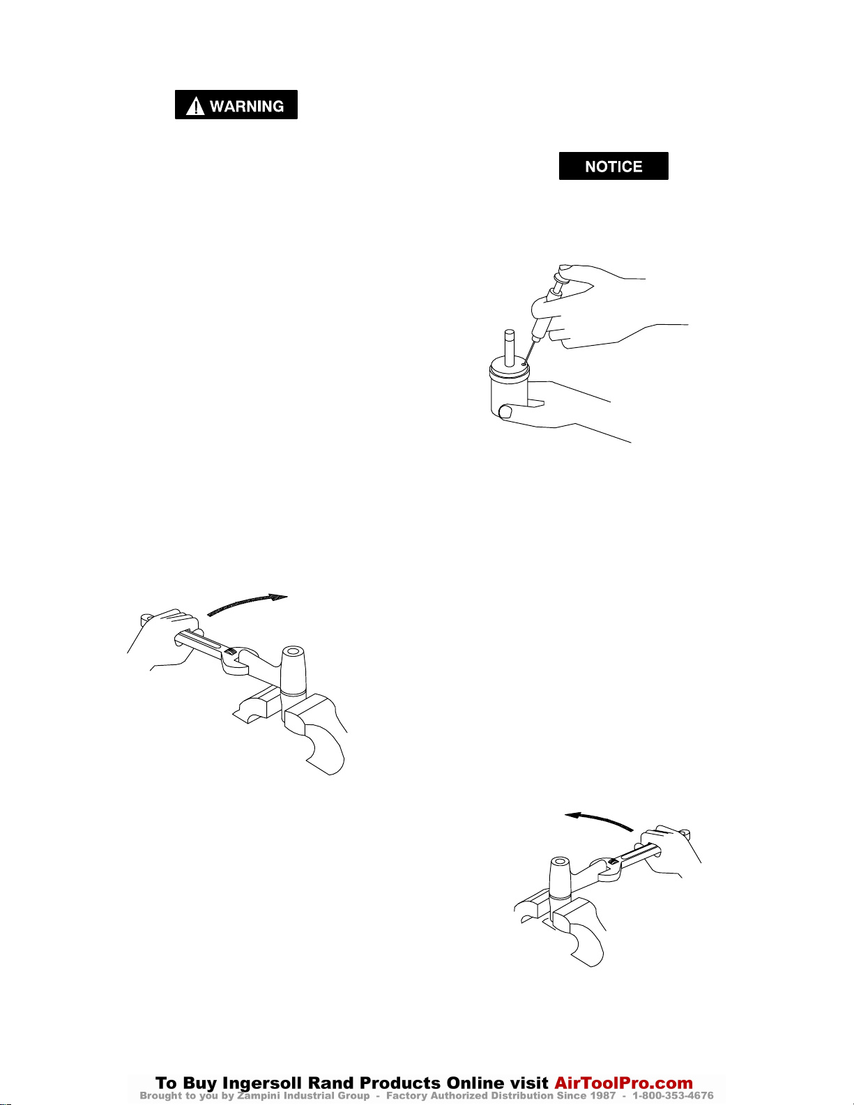
1. For model 180PQ1 or 280PQ1, use a pointed probe
to to push the Spring Seat (75) against the Retaining
Sleeve Spring (74). While the Spring is compressed,
use another pointed probe or thin blade screwdriver
to remove the Retaining Ring (76). Lift the Spring
Seat, Spring and Bit Retaining Sleeve (73) off the
Drive Shaft (50) and remove the Bit Retaining Ball
(72).
2. Remove the Rubber Housing Boot (77).
3. Using copper–covered vise jaws, carefully grasp the
flats of the Mechanism Cover (67) with the output
end of the Drive Shaft downward.
4. Using an adjustable wrench, unscrew the the Motor
Housing Assembly (1) from the Mechanism Cover.
This is a left–hand thread, rotate the Motor Housing
clockwise to remove it. (Refer to Dwg. TPD1264)
CLOCKWISE TO LOOSEN
(Dwg. TPD1264)
9. Using the syringe and fluid from the Fluid Replacement Kit (Part No. EQ106S–K400), fill the mechanism with the fluid furnished in the Kit. (Refer to
Dwg. TPD1265)
DO NOT SUBSTITUTE ANY OTHER FLUID.
Failure to use the fluid provided could damage the
tool, increase maintenance and decrease performance. Use only clean fluid in these tools.
(Dwg. TPD1265)
10. Submerge the fill opening in the remainder of the
fluid, and using a wrench, rotate the Drive Shaft to
purge any remaining air from the system.
11. Thread the Oil Plug with the Oil Plug Seal into the
mechanism until it is snug.
12. Using a 1.5 mm hex wrench, turn the Torque Adjustment Screw clockwise until it stops. This is the maximum torque position.
13. Wipe the outside of the mechanism dry and clean and
remove the Oil Chamber Plug. Using the syringe,
withdraw .4 cc of fluid.
14. Install the Oil Chamber Plug and tighten it between
20 and 25 in–lb (2.3 and 2.8 Nm) torque.
15. Insert the mechanism assembly, output end leading,
into the Mechanism Cover clamped in the vise jaws.
16. Insert the hex end of the rotor shaft into the hex recess at the rear of the Drive Shaft and thread the assembled Motor Housing onto the Mechanism Cover.
This is a left–hand thread. Rotate the Housing coun-
terclockwise to tighten it. (Refer to Dwg. TPD1266)
COUNTERCLOCKWISE TO TIGHTEN
5. Lift the assembled motor off the Mechanism Cover
and pull the mechanism assembly out of the Cover.
6. Using a 1.5 mm hex wrench, rotate the Torque Adjustment Screw (37) clockwise until the Screw stops.
Rotate the Screw counterclockwise until it stops or
makes six complete revolutions.
7. Using the special Tee Wrench furnished in the Tool
Kit (Part No. 180PQ–99), remove the Oil Plug (58)
and Oil Plug Seal (59).
8. With the oil plug opening downward over a container,
rotate the Drive Shaft to purge the fluid from the
mechanism.
(Dwg. TPD1266)
21
Page 22
MAINTENANCE SECTION
DISASSEMBLY
General Instructions
1. Do not disassemble the tool any further than necessary to replace or repair damaged parts.
2. When grasping a tool or part in a vise, always use
leather–covered or copper–covered vise jaws to protect the surface of the part and help prevent distortion. This is particularly true of threaded members
and housings.
3. Do not remove any part which is a press fit in or on
an assembly unless the removal of that part is necessary for repairs or replacement.
4. Do not disassemble the tool unless you have a
complete set of new gaskets and O–rings for
replacements.
Disassembly of the Impulse Mechanism
1. For model 180PQ1 or 280PQ1, use a pointed probe
to to push the Spring Seat (75) against the Retaining
Sleeve Spring (74). While the Spring is compressed,
use another pointed probe or thin blade screwdriver
to remove the Retaining Ring (76). Lift the Spring
Seat, Spring and Bit Retaining Sleeve (73) off the
Drive Shaft (50) and remove the Bit Retaining Ball
(72).
For model 280P, use a hooked wire to pull the Retaining Pin Spring (52) out of the end of the Drive
Shaft (50) and remove the Socket Retaining Pin (51).
2. Remove the Rubber Housing Boot (77).
3. Using copper–covered vise jaws, carefully grasp the
flats of the Mechanism Cover (67) with the output
end of the Drive Shaft downward.
4. Using an adjustable wrench, unscrew the the Motor
Housing Assembly (1) from the Mechanism Cover.
This is a left–hand thread, rotate the Motor Housing
clockwise to remove it. (Refer to Dwg. TPD1264.)
5. Lift the assembled motor off the Mechanism Cover
and pull the mechanism assembly out of the Cover.
Remove the Bushing Spacer (69).
6. Grasp the flats of the Housing Assembly (36) in vise
jaws with the output end of the Drive Shaft downward.
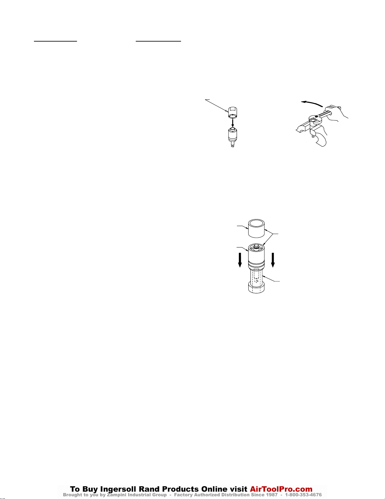
7. Insert the pins of the spanner plug from the No.
180PQ–99 Tool Kit into the two holes in the Housing
Cap (42). Using a wrench on the plug, unscrew and
remove the Housing Cap from the Housing Assembly. (Refer to Dwg. TPD1267)
COUNTERCLOCKWISE TO LOOSEN
SPANNER PLUG
(Dwg. TPD1267)
8. Stand the disassembly arbor from the Tool Kit, large
end downward, on a workbench or the table of an
arbor press. Insert the output end of the Drive Shaft
into the central opening and either tap the Housing
downward off the components or use the pressing
sleeve in the Kit to press the Housing downward off
the components. (Refer to Dwg. TPD1268)
PRESSING
SLEEVE
HOUSING
TAP EDGE LIGHTLY
WITH BRASS HAMMER
OR USE PRESSING
SLEEVE FROM TOOL
KIT
DISASSEMBLY ARBOR
FROM TOOL KIT
(Dwg. TPD1268)
9. Disassemble the components of the mechanism in the
sequence shown in Drawing TPA1329 on Page 17.
22
Page 23
Disassembly of the Motor
MAINTENANCE SECTION
1. Grasp the Motor Housing (1) in vise jaws with the
shaft of the Rotor (30) upward.
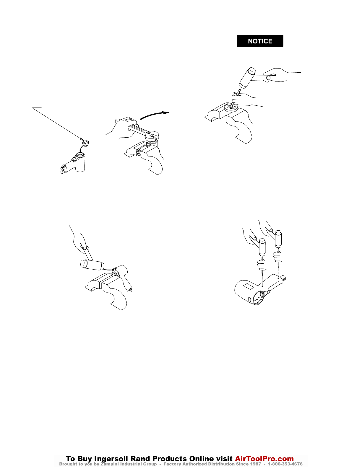
2. Insert the pins of the end plate spacer spanner into the
holes in the Front End Plate Spacer (35). Using a
wrench, unscrew and remove the Spacer. This is a
left–hand thread; rotate the wrench clockwise to
remove the Spacer. (Refer to Dwg. TPD1269)
END PLATE
SPACER SPANNER
CLOCKWISE
TO LOOSEN
(Dwg. TPD1269)
3. Reposition the Motor Housing in the vise jaws so that
the vise jaws grip the end of the rotor shaft and the
handle grip of the Housing is downward. Tap the
edges of the Housing surrounding the motor bore
with a plastic hammer to separate the Housing from
the motor. (Refer to Dwg. TPD1270)
Do not enlarge or damage the shaft hole in the
End Plate.
(Dwg. TPD1271)
7. Press the Reverse Lever Pin (4) out of the Reverse
Lever (3) and remove the Reverse Lever Detent Ball
(5), Reverse Lever Detent Spring (6), Reverse Valve
Assembly (17) and the Reverse Valve Spring (19).
8. Using a pin punch, tap the Throttle Retaining Pin (16)
and the Deflector Retaining Pin (22) out of the Handle. The Throttle Retaining Pin is protected by an
embossed circular pad of metal. Insert the pin punch
into the middle of the pad to locate the Pin. (Refer to
Dwg. TPD1272)
(Dwg. TPD1270)
4. Remove the motor from the vise jaws and remove the
Front End Plate (32), Front End Plate Bearing (34),
Cylinder Assembly (27) and Vanes (31) from the
Rotor.
5. On the table of an arbor press, support the Rear End
Plate (25) with blocks as close to the Rotor as possible and press the Rotor out of the Rear End Plate
and Rear Rotor Bearing (26).
6. To remove the Rear Rotor Bearing from the Rear End
Plate, use a small drift or pin punch through the central opening of the Rear End Plate to tap the Bearing
out of the End Plate. (Refer to Dwg. TPD1271)
(Dwg. TPD1272)
9. Grasp the Trigger (14) and pull the assembled throttle
out of the Motor Housing.
10. Using a pin punch and without damaging the Trigger
(14), remove the Trigger Pin (15).
11. Slide the Throttle Bushing Assembly (7) off the shaft
of the Throttle Rod Assembly (12).
12. Using a thin blade screwdriver, remove the Valve
Retaining Ring (11) and slide the Throttle Valve Assembly (9) off the shaft of the Throttle Valve Rod.
13. Grasp the Exhaust Deflector Assembly (21) and pull
it out of the Housing.
14. Unscrew and remove the Inlet Bushing (20).
23
Page 24
MAINTENANCE SECTION
ASSEMBLY
General Instructions
1. When grasping a tool or part in a vise, always use
leather–covered or copper–covered vise jaws to protect the surface of the part and help prevent distortion. This is particularly true of threaded members
and housings.
2. Always press on the inner ring of a ball–type bearing
when installing the bearing on a shaft.
3. Always press on the outer ring of a ball–type bearing
when pressing the bearing into a bearing recess.
4. Except for bearings and mechanism parts, always
clean every part and wipe every part with a thin film
of oil before installation.
5. Wipe a thin film of mechanism fluid on all internal
mechanism components before installing them in the
mechanism.
6. Apply a film of o–ring lubricant to every o–ring before installation.
Assembly of the Motor
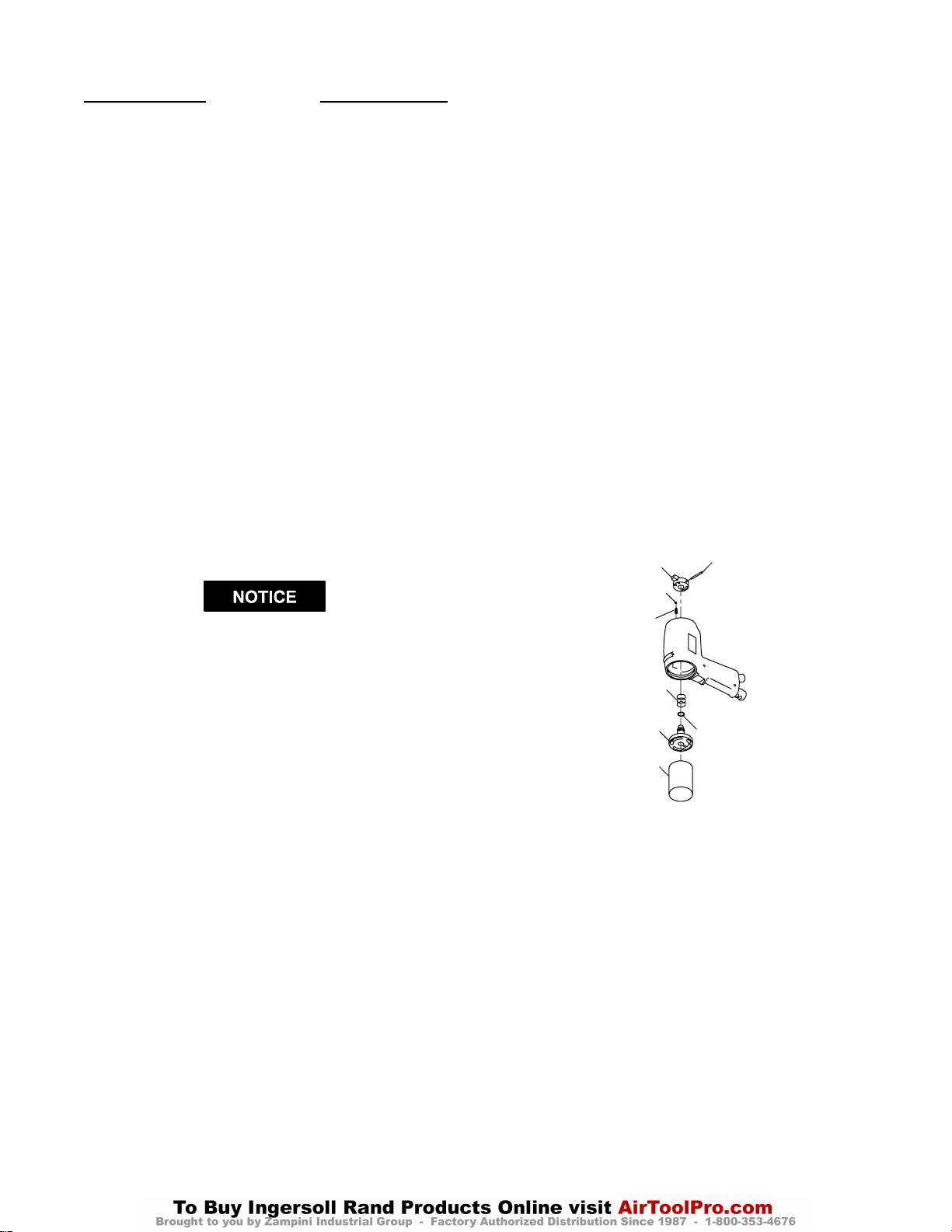
1. Thread the Inlet Bushing (20) into the bottom of the
handle of the Motor Housing (1) and tighten it between 30 and 35 ft–lb (40 and 47 Nm) torque.
2. Position the Exhaust Deflector Assembly (21) in the
bottom of the motor housing handle and install the
Deflector Retaining Pin (22) to secure it in position.
9. Insert the assembled Trigger into the Housing. Make
certain the widest end of the Trigger is nearest the
motor bore and the narrowest portion of the Throttle
Valve aligns with hole for the Throttle Retaining Pin
(16). Install the Pin making certain it captures the
Throttle Valve and secures the assembled Trigger.
10. Install the Reverse Valve Seal (18) on the hub of the
Reverse Valve (17).
11. Place the Reverse Valve Spring (19) over the hub of
the Reverse Valve and insert the assembly, small hub
leading, into the motor bore of the Housing. Insert the
small hub through the Housing until it protrudes
through the rear of the Housing. Position a 1–1/4”
(32 mm) diameter metal rod about 3” (75 mm) long
against the face of the Reverse Valve and stand the
rod on a workbench with the weight of the Housing
compressing the Reverse Valve Spring.
12. Place the Reverse Lever Detent Spring (6) followed
by the Reverse Lever Detent Ball (5) into the hole in
the face at the rear of the Motor Housing. Capture the
Ball and Spring in position by installing the Reverse
Lever (3) onto the hub of the Reverse Valve. Make
certain the Reverse Lever Alignment Pin (2) enters
the notch on the face of the Lever and that the crosshole in the hub of the Reverse Valve aligns with the
crosshole in the Lever. (Refer to Dwg. TPD1273).
REVERSE LEVER
DETENT BALL
REVERSE LEVER PIN
It may be necessary to slide the Assembly in or out
in order to align the groove in the Assembly with
the pin hole.
3. Install the Throttle Rod Seal (13) in the groove on the
large hub of the Throttle Rod (12).
4. Install the Throttle Valve Seal (10) in the groove on
the large hub of the Throttle Valve (9).
5. Slide the Throttle Valve, Valve Seal end first, onto the
Throttle Valve Rod.
6. Secure the Throttle Valve Assembly by installing the
Valve Retaining Ring (11) in the small groove on the
Throttle Valve Rod.
7. Install the three Throttle Bushing Seals (8) in the
grooves on the Throttle Bushing (7).
8. Slide the Throttle Bushing Assembly onto the shaft of
the Throttle Valve Rod and position the Trigger (14)
on the same shaft. Install the Trigger Pin (15).
DETENT SPRING
REVERSE VALVE SPRING
REVERSE VALVE
METAL ROD
REVERSE VALVE O–RING
(Dwg. TPD1273)
13. Lightly tap the Reverse Lever Pin (4) into the hole in
the Lever and into the hole in the hub of the Reverse
Valve. Remove the assembly from the metal rod and
work the Lever several times to make certain all parts
function smoothly.
24
Page 25
MAINTENANCE SECTION
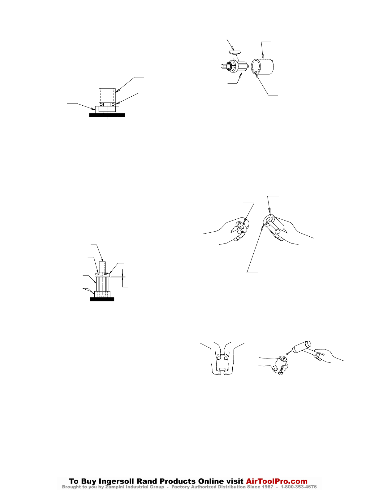
14. Using an arbor press and a piece of tubing that contacts the outer ring of the bearings, press the Front
End Plate Bearing (34) into the Front End Plate (32)
and the Rear End Plate Bearing (26) into the Rear
End Plate (25). (Refer to Dwg. TPD1274)
TUBING
BEARING
END PLATE
(Dwg. TPD1274)
15. Stand the Rotor (30) on the table of an arbor press. It
should be upright on a flat metal plate having a clearance hole for the shaft. The shaft with the hex must
be upward.
16. Place a 0.001” (0.025 mm) shim on the upward surface of the large portion of the rotor body. Using a
piece of tubing that contacts the inner ring of the
bearing, press the Front Rotor Bearing and Front End
Plate, End Plate leading, onto the shaft of the Rotor
until the End Plate contacts the shim. Remove the
shim. (Refer to Dwg. TPD1275)
VANE
ROTOR
CYLINDER
FRONT END PLATE
ALIGNMENT PIN
(Dwg. TPD1276)
19. Place the Rear End Plate and Bearing against the face
of the Cylinder, Bearing end trailing. Make certain
the Rear End Plate Alignment Pin (28) protrudes
through hole in the End Plate.
20. Apply a thin film of Ingersoll–Rand No. 67 Grease to
the face of the Rear End Plate and place the Rear End
Plate Spacer (24) against the end plate face. Make
certain the Alignment Pin enters the hole in the
Spacer and there is sufficient grease to hold the
Spacer against the End Plate. (Refer to Dwg.
TPD1278)
PIN HOLE
ALIGNMENT PIN
PRESSING PLUG
FRONT ROTOR
BEARING
ROTOR
PLATE WITH ROTOR
SHAFT CLEARANCE
FRONT END PLATE
0.001” (0.025 mm)
SHIM SPACE
(Dwg. TPD1275)
17. Coat each Vane (31) with a thin film of oil and insert
a Vane into each of the rotor vane slots with the
straight edge of the Vane outward.
18. Install the Cylinder (27) over the Vanes and Rotor
with the end of the Cylinder having the Alignment
Pin (29) in the middle of the four holes positioned
toward the Front End Plate. (Refer to Dwg.
TPD1276). Make certain the Pin enters the hole in the
face of the Front End Plate.
GREASE LIGHTLY
(Dwg. TPD1278)
21. Insert the assembly, End Plate Spacer leading, into
the Motor Housing making sure the Alignment Pin
protruding through the Spacer enters the proper hole
in the Reverse Valve. It may be necessary to tap the
assembly into position with a brass or plastic
hammer. (Refer to Dwg. TPD1279)
(Dwg. TPD1279)
25
Page 26
MAINTENANCE SECTION
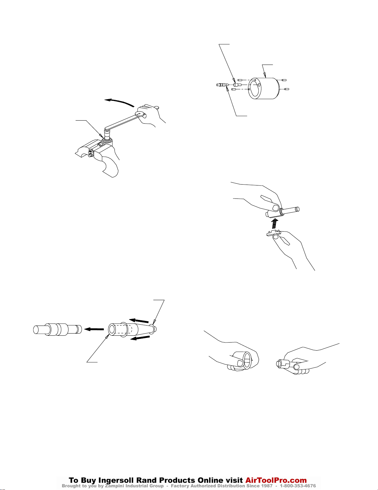
22. Grasp the handle of the Motor Housing in vise jaws
with the rotor shaft upward. Thread the Front End
Plate Spacer (35) into the Housing and using the end
plate spacer spanner, tighten the Spacer to 12 ft–lb
(16 Nm) torque. This is a left–hand thread; rotate
the wrench counterclockwise to tighten.
(Refer to Dwg. TPD1280).
COUNTERCLOCKWISE TO TIGHTEN
SPANNER
(Dwg. TPD1280)
23. After installing the Front End Plate Spacer, grasp the
shaft of the Rotor and rotate it by hand. If the Rotor
does not turn easily, disassemble the motor unit and
determine where the assembly is binding. The motor
must rotate freely before proceeding further with the
assembly.
Assembly of the Impulse Mechanism
RELIEF VALVE
LINER
LONG END OF SPRING GUIDE
WITH GROOVE
(Dwg. TPD1282)
3. Place a Blade (53) into one of the slots of the Drive
Shaft (50) with the Blade Assembly Pins (54) inward.
4. From the opposite side of the Shaft, encircle each Pin
with a Blade Spring (55).
5. Install the Assembly Pins of the remaining Blade in
the open ends of the Springs.
(Refer to Dwg. TPD1283).
1. Insert the long shaft with the annular groove of the
Spring Guide (48) into the central opening of the
O–ring installer furnished with the Tool Kit (Part
No. 180PQ–99). Place the Spring Guide Seal (49) on
the tapered end of the installer and roll the Seal up the
taper and into the groove on the large body of the
Spring Guide.
(Refer to Dwg. TPD1281)
SPRING GUIDE SEAL
O–RING INSTALLER
(Dwg. TPD1281)
2. Insert the Relief Valve (47), large end trailing, into
the Liner (45). Insert the assembled Spring Guide,
long hub with annular groove leading, into the Liner
against the Relief Valve. (Refer to Dwg. TPD1282)
(Dwg. TPD1283)
6. Compress the Springs with the Blades until both
Blades are flush with the Drive Shaft and install the
assembly in the Liner with the output end of the
Drive Shaft protruding out the end of the Liner containing the Spring Guide. (Refer to Dwg. TPD1284).
Make certain the ends of the Blades are flush with the
ends of the Liner.
(Dwg. TPD1284)
26
Page 27
MAINTENANCE SECTION
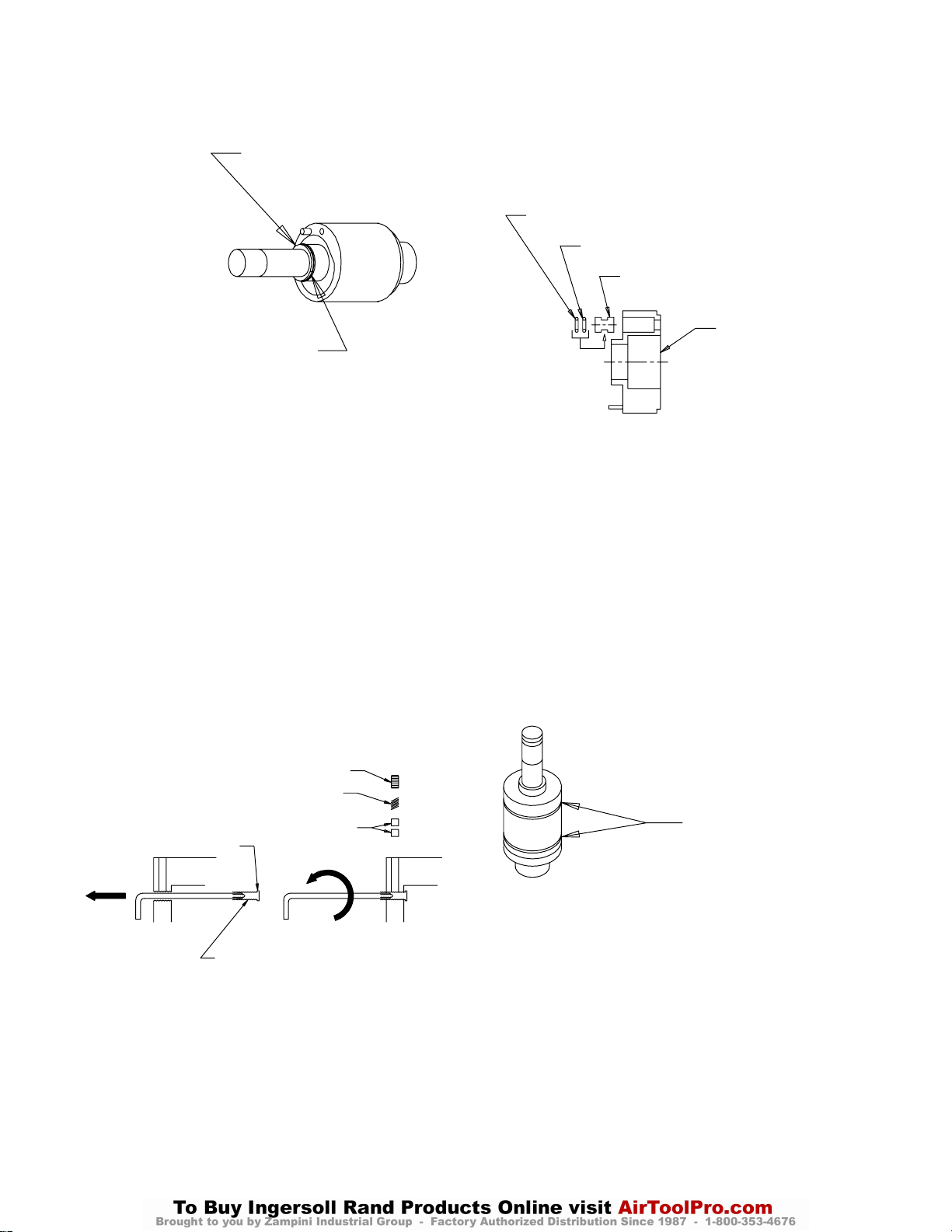
7. Install the Drive Shaft Seal (65) followed by the Seal
Back–up Ring (66) on the Drive Shaft against the
hub. (Refer to Dwg. TPD1285)
SEAL BACK–UP RING
DRIVE SHAFT SEAL
(Dwg. TPD1285)
8. The Torque Adjustment Screw (37) can only be
installed from the liner end of the Impulse Housing
(35). If the Torque Adjustment Screw was removed,
proceed as follows:
a. Insert a 1.5 mm hex wrench into the threaded hole
for the Torque Adjustment Screw from the oil
plug end of the Housing.
b. From the opposite end of the Housing, install the
hex of the Torque Adjustment Screw onto the hex
wrench.
c. Push the Screw and wrench toward the threaded
hole until it contacts the face of the Housing.
d. While applying finger pressure to the rivet end of
the Screw, rotate the wrench counterclockwise to
thread the Screw into the Housing. Continue
rotating the Screw until the rivet end stops against
the face of the Housing.
e. Insert the two Adjustment Screw Plug Locks (38)
and the Plug Lock Spring (39) into the crosshole
leading to the Adjustment Screw. Thread the Plug
Lock Screw (40) into the same hole to capture the
components. (Refer to Dwg. TPD1286)
LOCK SCREW
LOCK SPRING
9. If the Oil Stop Cap Assembly (60) was removed from
the Front Liner Cover (56), install the Stop Cap O–
ring (61) and Back–up Ring (62) in the groove of the
Cap and insert the assembly into the Cover.
(Refer to Dwg. TPD1287)
BACK–UP RING
STOP CAP O–RING
OIL STOP CAP
FRONT LINER COVER
(Dwg. TPD1287)
10. Install the Liner Cover O–ring (44) in the groove on
the large hub of the Rear Liner Cover (43). Align the
pin holes in the face of the Cover with the two Liner
Pins (46) at the rear of the Liner and place the Cover
against the Liner. A groove will be formed between
the Liner and Cover for the Rear Liner Seal (64). Do
not attempt to put the Seal in the groove at this time.
11. Align the pin holes in the Front Liner Cover (56) with
the Pins in the front face of the Liner and place the
Cover against the face of the Liner. Another groove
will be formed between the Liner and Cover for the
Front Liner Seal (63). Install both the Front and Rear
Liner Seals in the grooves at this time and stand the
assembly on the workbench with the output end of
the Drive Shaft upward. (Refer to Dwg. TPD1288)
RIVETED END
TORQUE ADJUSTMENT SCREW
PLUG LOCKS
(Dwg. TPD1286)
LINER SEALS
(Dwg. TPD1288)
12. Apply a thin film of grease to the Liner O–ring (41)
and install it in the forward bore of the Housing.
13. Lubricate the Front and Rear Liner Seals and after
orienting the Housing to the proper position, install
the Housing over the Liner.
27
Page 28
MAINTENANCE SECTION
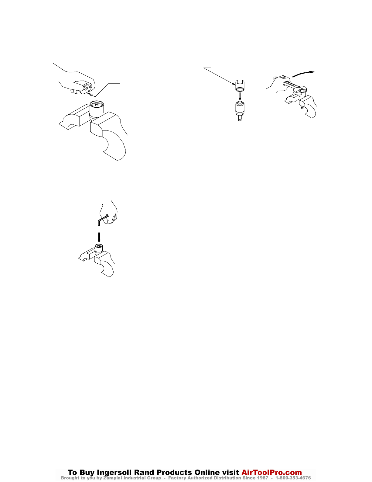
14. Grasp the flats of the Housing in vise jaws with the
output spindle downward. Remove the Rear Liner
Cover Assembly and put grease in the central opening of the Cover. (Refer to Dwg. TPD1289)
GREASE
(Dwg. TPD1289)
15. Reinstall the Cover Assembly and use a hex wrench
to push it below the threads at the rear of the Housing. (Refer to Dwg. TPD1290)
PUSH DOWN
16. Install the Housing Cap (42) and using the spanner
plug furnished in the Tool Kit, tighten the Cap between 5 and 6 ft–lb (8 and 9 Nm) torque. (Refer to
Dwg. TPD1291)
SPANNER PLUG
CLOCKWISE TO TIGHTEN
(Dwg. TPD1291)
17. Make certain the Drive Shaft rotates freely and then
fill the mechanism with fluid and reassemble the tool
as instructed in the section, CHANGING THE
MECHANISM FLUID.
(Dwg. TPD1290)
 Loading...