

Page 1
Move 5000
User Guide
Optional
www.ingenico.com
28-32, boulevard de Grenelle, 75015 Paris - France / (T) +33 (0)1 58 01 80 00 / (F) +33 (0)1 58 01 91 35
Ingenico - SA au capital de 47 656 332 / 317 218 758 RCS Nanterre
Page 2
Contents
1_Introduction
2_Presentation
2_1 Content of the box
2_2 Overview on the MOVE/5000
2_3 Keyboard details and functionality
2_4 Touch panel
3_Use of the terminal
3_1 Switching off the terminal
3_2 Reading card
3_3 Scan Engine (Optional)
4_Installation
4_1 Recommendations
4_2 Terminal connections
4_2_1 uUSB
4_2_2 DC Jack
4_2_3 MicroSD memory Card
4_2_4 Audio Jack (optional)
4_3 Opening trap door
4_4 SAMs & SIMs
4
5
5
6
8
9
10
10
10
12
13
13
14
14
14
15
15
16
17
Move 5000
900017771 R11 000 12/0419
2
Copyright© 2019 Ingenico
All rights reserved
Page 3
4_5 Battery
4_5_1 Main characteristics
4_5_2 Installing the battery
4_5_3 Charging the battery
4_5_4 Changing the battery
4_6 Paper roll
4_6_1 Main characteristics of INGENICO paper roll
4_6_2 Installing paper roll
5_Recommendations
5_1 Safety
5_2 Security of your terminal
5_3 Fixed installation
18
18
18
20
21
22
22
23
24
24
25
26
6_Standards
6_1 Environment (WEEE, Batteries and
Packaging)
6_2 FCC/IC Compliance
6_3 MIC Compliance
7_Troubleshooting
Move 5000
900017771 R11 000 12/0419
3
Copyright© 2019 Ingenico
All rights reserved
28
28
29
33
34
Page 4
1_Introduction
We hope that you will be fully satised with yo ur new terminal
MOVE/ 5000. This terminal is available in different models. Please
select by yourself in this documentation items related to yo ur model.
Read this guide to unders tand and make the be st use of yo ur terminal.
It presents you the n ecess ary information ab out use, installation ,
maintenance, safet y and security re commen dations.
WARRANTY / SECURITY
Use only the power supply included with the pro duct to
ensure be st per formance and safe ty. Maintenance should
only be provided by Ingenic o authorized technician.
Failure to comply with these ins tructions will void the
manufacturer’s responsibility.
This symbol indicates an important Warning .
This symbol indicates a piece of advice.
Move 5000
900017771 R11 000 12/0419
4
Copyright© 2019 Ingenico
All rights reserved
Page 5
2_Presentation
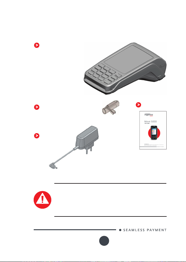
2_1 Content of the box
MOVE/5000 terminal unit equipped
with a paper roll
A battery pack disconnected
Power adapter
WARNING
The power s upply unit provided with yo ur equipment
is specially designed for Ingenico terminals. Do not use
any other power supply. The use of a power s upply with
apparently similar voltage/current characteristics may
damage your terminal.
Move 5000
900017771 R11 000 12/0419
User guide
5
Copyright© 2019 Ingenico
All rights reserved
Page 6
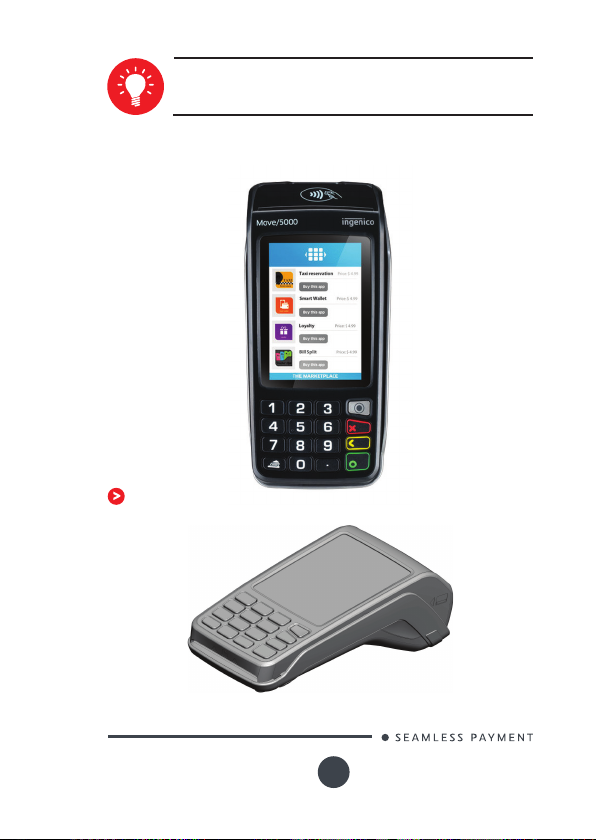
ADVICE
Keep the packaging. It must be re-used whenever the terminal is shipped.
2_2 Overview of the MOVE/5000
Terminal unit
3’’5 LCD Display with
touch panel
Easy loading printer
Backlit keyboard
Smart card reader
Move 5000
900017771 R11 000 12/0419
Magnetic
card reader
6
Copyright© 2019 Ingenico
All rights reserved
Page 7
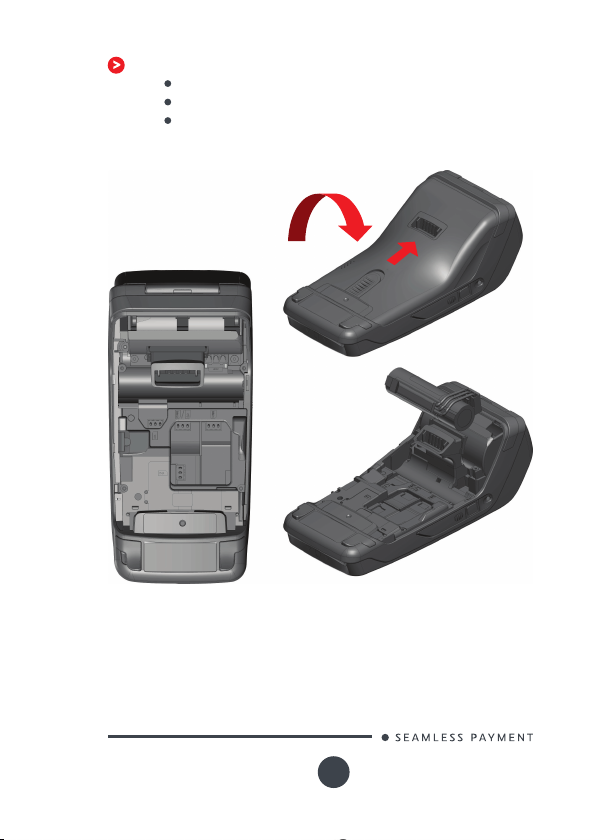
Compartment where are located:
the battery pack
the modules SAM1/SAM2/SIM1/SIM2
the 2nd Sma rt card reader (optional)
Move 5000
900017771 R11 000 12/0419
7
Copyright© 2019 Ingenico
All rights reserved
Page 8
Weight
(without p aper roll no r
battery)
310g
Dimensions (L x w x h) 169x78x57 mm
Electrical mains network
Connections on terminal
100-240VAC / 50-60 Hz - Class II
equipment
Micro USB AB serial link
Power connector
Contac ts for Cradle
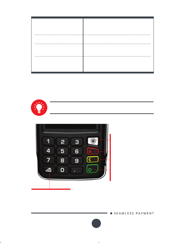
2_3 Keyboard details and functiona-
lity
Some keys can have other functions according to the applications that are in the terminal.
The functions key accesses
the different application
menus
The red key cancels the
procedure in progress
The yellow key cancels the
last character
The green key validates input
selections and information.
It is also used to switch on
the terminal
Feed paper a few centimers
if pressed for a long time
(more than 2 seconds)
Move 5000
900017771 R11 000 12/0419
8
Copyright© 2019 Ingenico
All rights reserved
Page 9
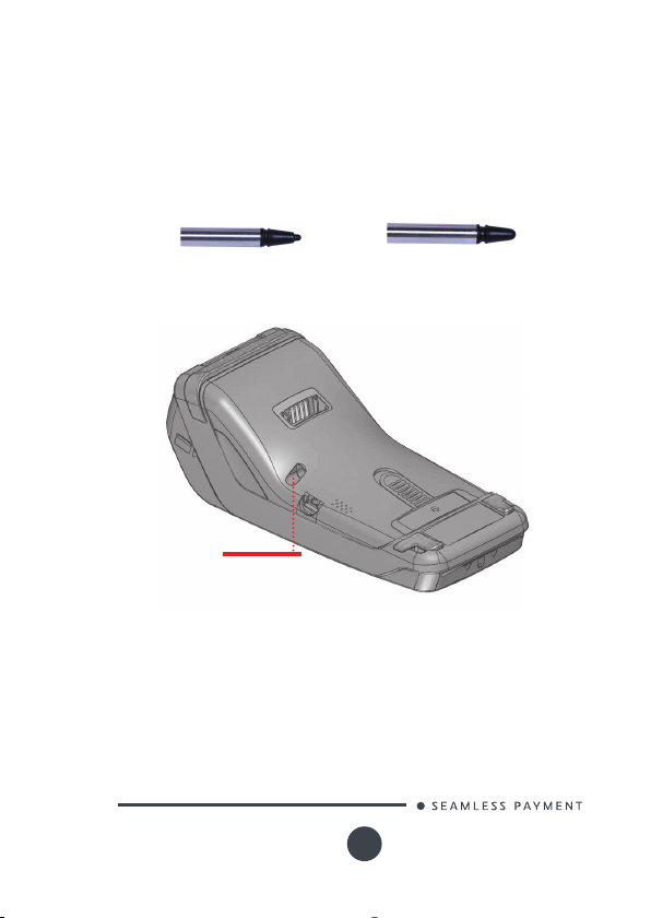
2_4 Touch panel
Move/50 00 features touch screen display, allowing user intera ction
via nger or a st ylus. Note that there are 2 different stylus pens
depending on the touch screen type, o ne for Move/5000 with resistive
touch screen and one for Move/ 5000 with capacitive touch screen as
shown below :
Resistive stylus
Stylus location
Capacitive stylus
Retrac table st ylus is located at the back cover as shown above :
Move 5000
900017771 R11 000 12/0419
9
Copyright© 2019 Ingenico
All rights reserved
Page 10
3_Use of the terminal
ADVICE
Before to use the terminal, always check if the roll of paper
is present.
3_1 Switching off the terminal
If the bat tery is empty and th e terminal in use is removed from its
base, th e terminal automatically shuts of f.
It may also be switch by pressing simultane ously and (yellow
key) for one second.
In order to restart the terminal, p ress on the keyboard.
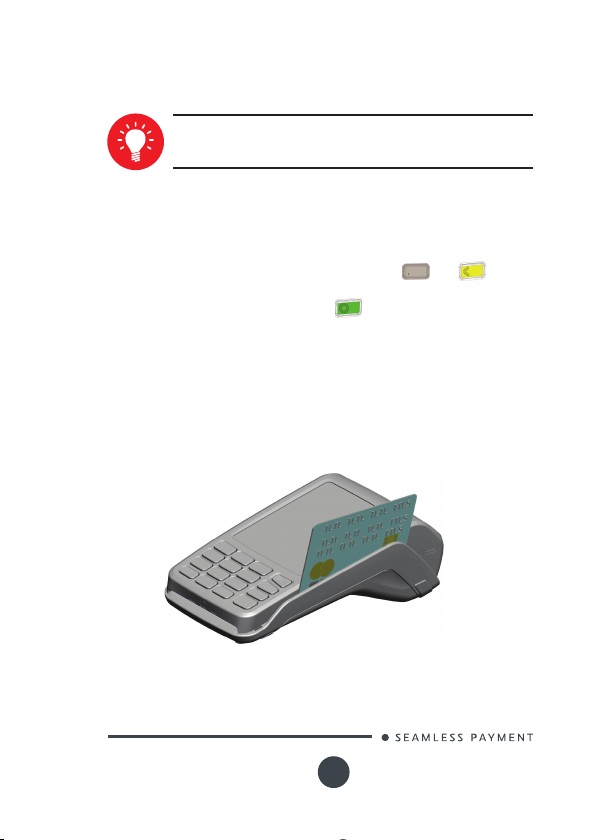
3_2 Reading card
Magnetic stripe card
The card c an be read either from b ottom to top or from top
to botto m, with the s tripe facing the terminal.
Use a regula r movement in o rder to ensure a reliable card
reading.
Move 5000
900017771 R11 000 12/0419
10
Copyright© 2019 Ingenico
All rights reserved
Page 11
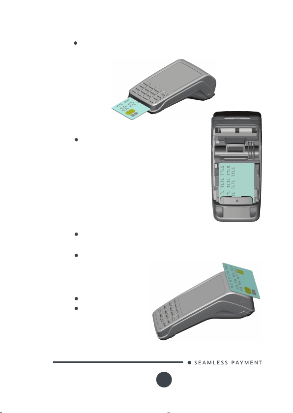
Smart card
Card reader: insert the card horizontally with the chip facing
upwards and leave in position through out the transac tion.
2nd card reader (Optional): is located
under terminal trapdoor (on ba ck of
the terminal ). Insert the card up side
down chip facing the terminal.
Contactless (optional)
Bring the card rmly up to the active zon e.
Keep the ca rd close to the reader during the
transac tion
The 4 virt ual LEDs are displayed during the
transac tion.
The terminal behavior fo r the cardh older may
depend on:
The terminal environment
Local usage (language…)
Move 5000
900017771 R11 000 12/0419
11
Copyright© 2019 Ingenico
All rights reserved
Page 12

3_3 Scan Engine (Optional)
An optional Camera Autofocus with LED or an optional Barcode module
can be t ted on back of Move/5 000 terminal (dedicated reference).
About c amera feature, 11.16.7B SDK minimum is required to have the
benet of Honeywell® Library.
Camera or Barecode location
Different formats barcode can be dec oded, e xhaustive list is given
below :
UPC
EAN
CODES 11,39, 93 & 128
Interleaved 2 of 5
CODABAR & CODABLOCK
GS1_DATABAR (RSS) & DATABAR_EXPANDED
QR_CODE
DATA _M ATR IX
AZTEC
PDF417 & Micro PDF 417
MAXICODE
PO STA L C ODES
If other types of barcode formats have to be deco ded, please share
your requ est with your Region Co ordination Manager to ch eck the
feasibility.
Move 5000
900017771 R11 000 12/0419
12
Copyright© 2019 Ingenico
All rights reserved
Page 13

4_Installation
4_1 Recommendations
Location of the Move5000
Place the ba se on at surface near an elec tric socket and acco rding
to the base to the teleph one or a Ethernet so cket. The terminal should
be placed far from any very hot zones, protected f rom vibratio ns,
dust, damp and elec tromag netic radiation (compu ter scre en, anti-th eft
barrie r etc. ).
Operating conditions
Ambient temperature from +0°C to +50°C
Max relative humidity 85% at +40°C
Battery charging conditions
Ambient temperature from +0°C to +40°C
Storage conditions
Ambient temperature from -20°C to +55°C
Max relative humidity 85% at +55°C
Move 5000
900017771 R11 000 12/0419
13
Copyright© 2019 Ingenico
All rights reserved
Page 14

4_2 Terminal connections
4_2_1 uUSB
There is an USB conne ctor (microAB) on th e left side of
the Move/5000 Wireless terminal (see below picture). This
connec tor manages Host and Slave connexions.
The terminal supports USB Keys with FAT16 or FAT32
The USB Key has to be use d with an USB a dapter (refers to
accessories section)
USB micro AB
Connector used for USB Key, etc...
*MicroAB co nnector durabili ty: up to 10 000 mating cycle s
4_2_2 DC Jack
Power Supply Jack
Connector used to plug DC power supply 5V delivered by Ingenico
Move 5000
900017771 R11 000 12/0419
14
Copyright© 2019 Ingenico
All rights reserved
Page 15

4_2_3 MicroSD memory Card
Insert the MicroSD M emory C ard into the connec tor slot as
shown on the gure.
MicroSD connector is locate d on terminal sid e.
The terminal supports Micro SD up to 32GB
microSD connector
4_2_4 Audio Jack (optional)
Move 5000
900017771 R11 000 12/0419
Audio Jack 3"5
15
Copyright© 2019 Ingenico
All rights reserved
Page 16

4_3 Opening trap door
CAUTION
Switch off the terminal before opening the trap door.
Turn the terminal an d unclip the trapdoor by pushing on the
clip with as shown with the arrows on the pictu re
Move 5000
900017771 R11 000 12/0419
16
Copyright© 2019 Ingenico
All rights reserved
Page 17

4_4 SAMs & SIMs
The conn ector modules s ecurit y SAM/ SIM are loc ated inside t he
terminal, in a clos ed comp artment.
SAMs and SIMs are indentied by the engraved marks on the
lower housing
When introducing a SA M/SIM in its slot, be su re to put the cut
corner as in dicated on the engraved marks
SAM 1 Connector
SAM 2 Connector
SIM 2 Connector (Dual SIM terminals)
or SAM3 connector
SIM 1 Connector
Move 5000
900017771 R11 000 12/0419
17
Copyright© 2019 Ingenico
All rights reserved
Page 18

4_5 Battery
4_5_1 Main characteristics
Characteristics Li-ion 2900 mAh
Charge
(power supply-1.5A)
Battery life
* The batte ry capacity depen ds on the model of term inal and it s use
4_5_2 Installing the battery
WARNING
Check that the terminal is not conne cted to the main elec tric
network.
Turn your terminal and unclip the batter y trapdo or by
pushing on th e button as shown on the picture
Disengage the trap door
Take the batter y pack included in the box
Locate the battery pac k connector beside the bat tery
compar tment
Plug the bat tery p ack connector a ccordin g to the
connector locating system and (as shown on pict ure).
Verify that it locks.
Place the battery pack in its compartment.
Close the batter y compa rtment trapdo or.
50% capacity in 1,5 h; full capacity
in 4 hours
450 transactions in GPRS with
fully charge d battery, printing and
backlit activated
Can remain powered ON up to
150 hours with connected GP RS
link and terminal in sleeping state
starting with fully charged bat tery
and withou t energ y consumption
related to ba cklit or radio link
Move 5000
900017771 R11 000 12/0419
18
Copyright© 2019 Ingenico
All rights reserved
Page 19

Battery compartment
Move 5000
900017771 R11 000 12/0419
19
Copyright© 2019 Ingenico
All rights reserved
Page 20

4_5_3 Charging the battery
When does the bat tery ne ed to be charged?
On initial star t up, charge the bat tery un der the environmental
conditions stated above
When use d daily, the terminal recharges its batteries each tim e it
is placed on it s base . Charging is automatic
When use d with a terminal p ower supply : conne ct the power
supply to Move5000 power conn ector.
How does the battery nee d to be charged?
The environ ment in which the charge takes place inuences
batter y lifetime and autono my (number of transa ctions)
The optimal conditions are as follows:
/ Charging away f rom any external heat s ource (radiator, sun,
enclose d area…)
/ The optimal temperature is bet ween +15°C and +25°C
How can the b atter y be charg ed?
Using the base
Place the ter minal on its base
Check if th e battery symb ol is ashing or moving (=battery
charging).
Using the terminal power supply (the terminal is out of it s base)
Connect the terminal power supply unit to use the jack connecto r
located on the lef t side of the terminal.
Connect the power supply unit to the power supply mains
network
Check to s ee if the batte ry symbol is a shing or moving(=b attery
charging)
Move 5000
900017771 R11 000 12/0419
20
Copyright© 2019 Ingenico
All rights reserved
Page 21

4_5_4 Changing the battery
It is imperative to use a bat tery au thorized by Ingenico.
There is danger of explosion if battery used is not approved
by Ingenico.
Remove the terminal from its base
Turn it off by pressing simultan eously and (yellow
key) for abo ut one se cond
Remove the b atter y trapdoor (se e section 4. 5. 2“ins ta lli ng
battery”)
Carefully disconnect battery, following the instruc tions below,
For stan dard bat tery :
Unlock the connec tor by
pressing the locking mechanism
as indicated by F1 arrow while
pulling this conne ctor (F2 arrow ).
Release traction on it as soon as
the connector comes unclipped
Finish extracting connector
by tilting it slightly (F 3 arrow)
to bring it away from the
terminal ho using
Following the ins tructions below fo r Hardpack battery :
Unlock the connec tor by moving up the
batter y pack latch (F1)
Finish extracting battery
pack by raising slig thly the
connec tor to bring b atter y pack
away from the terminal housing.
(F2)
Connect and install the new battery by following the
instruc tions in se ction 4.5.2 “Installing batter y”
Close the batter y trapdoor and charge the n ew battery.
See se ction «Charging the Batter y»
In order to preserve the environn ement, dispose us ed
batter y in compliance with current countr y recycling
legislation.
Move 5000
900017771 R11 000 12/0419
21
Copyright© 2019 Ingenico
All rights reserved
Page 22

4_6 Paper roll
4_6_1 Mains characteristics of INGENICO
paper roll
R40 pape r roll Characteristics Precisions
Colour White
Width
Diameter
Length
The ther mal paper can be deteriorated by poor storage
conditions, so we recommend yo u to avoid:
/ storage in hot wet places (near air-conditioner, humidity
higher than 85%)
/ exposure to sunlight or ultraviolet fo r long periods
/ contac t with organic solvents (solvent t ype adh esive)
/ direct contact with materials containing plasticizers (PVC
transparent folders or envelopes)
/ direct contact with «diazo» papers
/ direct contact with water
/ Rubbing or pressing the p aper too strongly
WARNING
For best produc t performance, only use heat sensitized
paper approved by In genico.
WARNING
Switch off the terminal prio r to installing a paper roll.
Use only paper approved by Ingenico.
The use of n on approved paper is likely to damage the
printer of your terminal.
58 mm
40 mm
About 18 metres
Move 5000
900017771 R11 000 12/0419
22
Copyright© 2019 Ingenico
All rights reserved
Page 23

4_6_2 Installing paper roll
Open the p aper com partment by lifting t he catch lo cated at
the rear of th e terminal and pull the cover to the rear of th e
terminal.
Insert the paper roll in the compartment following the
directions shown on the below pict ure
Pull the pap er up to the to p of the terminal
Maintain the paper and close the lid
Press simultaneously on both upper corners of the paper
ap, as shown by arrows on pic ture, until it clips into position
Move 5000
900017771 R11 000 12/0419
23
Copyright© 2019 Ingenico
All rights reserved
Page 24

ADVICE
If you insert a new R40 paper roll, tear off the rst length
(one complete turn to avoid printing on adhesive tape
footprint).
5_Recommendations
5_1 Safety
Powering down the Move/5000 :
Disconne ct the Move/5000 power supply block adapter from
the electrical mains network .
Lithium cell
The Move/5000 is tted with an internal lithium cell which can
only be accessed by a qualied technician.
Battery
Move5000 is tted with battery specially designed for this
terminal.
Only use the appropriate chargers and bat teries listed in the
Ingenico’s catalog ue.
Do not sho rt-circuit the battery.
Do not at tempt to op en the bat tery co ntainer.
Used batteries must be disposed of at t he appropriates sites.
WARNING
There is a risk of explosion if the battery is incorrectly replaced or is placed in a re.
Electrical power outlet
The electrical outlet must meet the following criteria :
Must be ins talled nea r the equipment and easily accessible;
Must meet standards and reg ulations in the countr y where
used;
For typ e A plug, th e protec tion of the installation must be
set to 20 A
SAR exposure
Maximum SA R value : 1.8 80 W/kg (LTE F DD I 2100 MHz)
Maximum simultaneous S AR value : 1.998 W/kg
Move 5000
900017771 R11 000 12/0419
24
Copyright© 2019 Ingenico
All rights reserved
Page 25

The power supply label contains seven symbols :
Double insulation symbol
DC current output
AC current input
DC Power jack polarity
In door use only
International Ef ciency Marking Protocol (Energy
Star Level 5)
International Ef ciency Marking Protocol (Energy
Star Level 6)
SAM1/SAM2/SIM1/(SAM3/SIM2) readers compartment
The trap door for battery, SAM1/S AM2/SIM1/(SAM3/ SIM2),
readers located underneath the terminal, must be in place during
the normal operation of the terminal. See s ections «Removal of
SAM1/S AM2/SIM, modules» as well as «Connec ting the bat tery».
On airplanes
Your handset must be switched of f by removing the battery pack.
Remove the b atter y from the terminal when o n an airplane.
Non-compliance with these safety rules may result in legal action
and/or a ban o n later acce ss to cellular net work services.
Explosion areas
Certain re gulations restric t the use of radio equipment in chemical
plants, fuel depot s and any site wh ere blasting is c arried out. You
are urged to comply with these reg ulations. T he terminal shall be
protec ted by a spe cially tte d and certi ed cover enabling use in
proximity to a fuel pump.
Move 5000
900017771 R11 000 12/0419
25
Copyright© 2019 Ingenico
All rights reserved
Page 26

Electronic health appliances
Your handset is a radio transmitter which may interfere with
health appliances, su ch as hearing aids, pacemaker, hospital
equipment, etc.
Your doctor or the equipment manufact urer will be able to
provide you with appropriate advice.
External connection
All external circuits co nnected to the Move/500 0 must be SELV
(Safet y Ext ra Low Voltage) and LP S (limited power source) within
the meaning of section 2.2 and 2.5 of the standard IEC6 0950 1:2005+/A1:2010 and EN60950-1:2006+/A11:2009+/A1:2010+/
A12:2011
Cleaning
To clean the terminal, use a soft cloth slightly moistened with
water. Do not clean th e electrical conne ctions ; do not use
solvents , detergents or abrasive products.
5_2 Security of your terminal
Your device fulls current applicable PCI PTS security requirements.
Upon receipt of your terminal you should check fo r signs of tampering
of the equipment. It is strongly advised that these checks are
performed reg ularly after receipt. You should check, for example: that
the keypad is rmly in place; that there is no evidence of un usual wires
that have be en conne cted to any port s on your ter minal or ass ociated
equipment , the chip card reader or any other part of your terminal.
Such che cks would p rovide warning of any unaut horised modications
to your terminal, and other suspicious b ehaviour of individuals that
have access to your terminal. Your terminal detect s any “tampered
state”. In this state the terminal will repeatedly ash the mes sage” Alert
Irruption!” and fur ther use of the terminal will not be possible. If you
obser ve the “Alert Ir ruption!” messa ge, you should conta ct the ter minal
helpdesk immediately.
You are stron gly advise d to ensure that privilege d access to your
terminal is only granted to s taff that have been independently veried
as being trustwor thy.
The terminal must never be put in or left at a location where it c ould be
stolen or replaced by another device.
Move 5000
900017771 R11 000 12/0419
26
Copyright© 2019 Ingenico
All rights reserved
Page 27

5_3 Fixed installation
If the device is to b e used in a sit uation where it is not pos sible for
the cardholder to pick up a nd shield their PIN entry th emselves, the
device may be used witho ut PIN shield, b ut it must b e installed in the
following manner:
a) The device must be angled at 45 or more, so that oversight of the PIN
entry from the rear of the device is not possible.
b) The device must either b e tte d in a swivel stan d – so that th e
customer can position the device in the best angle to prevent oversight
– or the device m ust be xed in the bes t possible p osition to prevent
oversight if such a generic position exis ts in the sp ecic enviro nment
to which the device is installed .
c) The device environment must be accompanied with conspicuous
notices and educational material which informs the customer to shield
their PIN during PIN entry.
d) The device mus t be deployed so that oversight fro m other
customers, either in different payment lan es, or in other areas of
the shopping environment, is prevented. This may be achieved
through the placement of the lane s and device, so that the customer
is automatically positioned bet ween the device keypad and other
customers. Alternatively, it may be a chieved by the environment in
which the device is installed, so that the checkou t itself shields the PIN
entry process.
e) The terminal is exclusively made for indoor use.
If the above conditions are not fullled, the device with PIN shield mus t
be used .
CAUTION
Positioning of the terminal on check stand must be in such a
way to make cardholder PIN (Personal Identication Number)
spying infeasible.
Installing device on an adjustable stand must be in such a
way that consumers can swivel the terminal sideways and/
or tilt it forwards/backwards to a position that makes visual
observation of the PIN-entry process difcult.
Positioning of in-store security cameras such that the PINentry keypad is not visible.
NEVER ask the customer to divulge their PIN Code. Customers
should be advised to ensure that they are not being overlooked when entering their PIN Code.
Move 5000
900017771 R11 000 12/0419
27
Copyright© 2019 Ingenico
All rights reserved
Page 28

6_Standards
6_1 Environment (WEEE, Batteries and
Packaging)
This produ ct is labele d in accordance with European Dire ctives
2002/9 6/EC concerning Waste Electrical and Ele ctronic E quipment
(WEEE) and 20 06/66/EC concerning Batteries and Accumulator s. Those
provisions are requiring pro ducers a nd manuf acturers to become liable
for take-b ack, treatment and recycling upon end of life of equipme nt
and batteries.
The ass ociated symbol mea ns that WEE E and waste
batteries must not be thrown away but collec ted
separately and rec ycled.
Ingenico ensures that efcient collection and recycling scheme s are
set-up for WEEE and bat teries according to the local reg ulation of you r
countr y. Please contact your retailers for m ore detaile d information
about th e compliance solution in pla ce for disposing of your old
produc t and use d batteries.
Packaging waste mus t also be colle cted separately to assure a proper
disposal and recycling.
Please note that prop er recycling of the elec trical an d electronic
equipment a nd waste batteries will ensure safety of human health and
environment.
Move 5000
900017771 R11 000 12/0419
28
Copyright© 2019 Ingenico
All rights reserved
Page 29

6_2 FCC/IC Compliance
You are cautio ned that changes or modications not exp ressly
approved by the par t responsible for compliance could void the
user’s au thorit y to opera te the equipment.
This equipment has been tested and found to comply with the limits
for a Class B digital device, pursuant to part 15 of the FCC Rules.
These limit s are designed to provide reasonable protection against
harmful interference in a residential installation. This equipment
generate s, uses a nd can radiate radio frequency energy and, if not
installed and used in accordance with the inst ruction, may cause
harmful interference to radio communications.
However, there is no guarantee that interference will not
occur in a particular ins tallation. If this equipment does ca use
harmful interference to radio or television reception which can
be determin ed by turning the equipment off and on, the user is
encoura ged to tr y to corre ct inter ference by one or more of the
following measures :
Reorient or relocate the receiving antenna.
Increase the separation bet ween the equipment a nd
receiver.
Connect the equipment into an o utlet on circuit different
from that to which the receiver is conne cted.
Consult th e dealer or an experienced radio/ TV technician
for help.
This device complies with Par t 15 of the FCC Rules and Industry
Canada licen se-exempt RSS standard(s). Oper ation is subje ct to the
following two co nditions:
(1) This device may not cause ha rmful inter ference, and
(2) This device must accept any interference received,
including interference that may cause undesired operation.
Le présent appareil est conforme aux CNR d ’Industrie Canada
applicables aux appareils radio exempt s de licence. L’exploitation
est auto risée aux deux conditions suivantes :
(1) l’appareil ne doit pas produire de brouillage, et
(2) l’utilisateur de l’appa reil doit accepter tout brouillage
radioélectrique s ubi, même si le b rouillage est susceptible
d’en compromettre le fonctionnement.
Move 5000
900017771 R11 000 12/0419
29
Copyright© 2019 Ingenico
All rights reserved
Page 30

Under Industry C anada reg ulations, this radio transmitter may
only operate using an antenna of a typ e and maximum (or less er)
gain approve d for the tr ansmitter by Industry Canada. To reduce
potential radio interference to other users, the antenna type and
its gain should be so chosen that the equivalent isotropically
radiated power (e.i.r.p.) is not more than that necessary for
successful communication.
Conform ément à la réglementatio n d’Indus trie Cana da, le présent
émetteur radio peut fonctionner ave c une antenne d’un type et
d’un gain maximal (ou inférieur ) approu vé pour l’émetteur par
Industrie Canada. Dans le but d e réduire les risques de b rouillage
radioélectrique à l ’intention des autres utilisateurs, il faut
choisir le type d’antenne et son gain de sorte que la puissan ce
isotrope rayonnée équivalente (p.i.r.e.) ne d épasse pas l’intensité
nécessaire à l’établissement d’un e communic ation satis faisante.
No changes shall be made to the equipment without the
permission of Ingenico as this may void the user’s authority to
operate the equipment.
Tout changement apporté à ce terminal non expressément
approuvé par Ingenico est susceptible d’ann uler le droit de
l’utilisateur à s e servir de cet équipement.
This produ ct meets the applicable Innovation, Science and
Economic D evelopment Canada technical specications. The
Ringer Equivalence Numb er (REN) indicate s the maximum
number of devices allowed to be conne cted to a telephone
interface. The termination of an interface may consist of any
combination of devices subject only to the requirement that t he
sum of the RENs of all the devices not exce ed ve. REN for this
device is 0.1.
Le présent appareil est conforme aux spécications techniques
applicables d’Innovation, Sciences et Développement
économique Canada. L’indice d’équivalence de la sonnerie (IES)
sert à indiquer le nombre maximal de dispositifs qui peuvent être
raccord és à une inter face téléphonique . La terminaison d’une
interface peut co nsister en un e combinaiso n quelconque de
dispositifs , à la seule condition que la s omme des IES de tous les
dispositifs n’excède pas cinq. L’IES pour cet appareil est de 0.1.
The device for operation in the ban d 5150–5250 MHz is only for
indoor us e to reduce the potential for harmf ul interference to co channel mo bile satellite systems. In addition, high-power radars
are allocate d as primar y users ( i.e. priority users) of the bands
5250–5350 MHz and 5650 –5850 MHz an d that the se radar s
could caus e interference and/or damage to L E-LAN devices .
Move 5000
900017771 R11 000 12/0419
30
Copyright© 2019 Ingenico
All rights reserved
Page 31

Les dispositifs fonc tionnant dans la bande de 5 150 à 5 250 MHz
sont rés ervés uniquement p our une utilisation à l’intérieur an
de réduire les risques de brouillage préju diciable aux
systèmes de satellite s mobiles utilisant les mêmes canaux.
D’autre part, les utilisateurs de radars de haute puis sance sont
désignés utilisateurs principaux (c.-à-d. , qu’ils ont la prio rité) des
bandes d e 5250 à 5350 MHz et de 5650 à 5850 MHz et, d’autre
part, que ces radars pourraient causer du brouillage et/ou de s
dommage s aux dispositifs de RL-EL.
Part 68 of F CC Rules
Model Name
Product : Move/Base Eth/Mod/BT
This equipment complies wit h Part 68 of the FCC rules and the
requirements adopted by the AC TA. On th e bottom of this equipm ent
is a label that contains, among other information , a product identier
in the format US : AA AEQ##TX XX X. If re queste d, this numb er must b e
provided to t he telephone company.
US MODEM
US : IEOMM01BM5000
This equipment uses th e following USOC jacks : ( RJ11C).
A plug and jack used to connect this equipment to the premises wiring
and telephone network must comply with the applicable FCC Part 68
rules and requirements adopted by the AC TA. A compliant telephone
cord and modular plug is provided with this produc t. It is desig ned to
be conne cted to a compatible m odular jack t hat is also compliant. Se e
installatio n instru ctions for details.
Move 5000
900017771 R11 000 12/0419
31
Copyright© 2019 Ingenico
All rights reserved
Page 32

The REN is used to determine the number of devices that may b e
connec ted to a telephone line. Excessive R ENs on a telep hone line may
result in the d evices not rin ging in response to an inc oming call. In mo st
but not all areas, the sum of RENs should not exce ed ve (5.0). To be
certain of the number of devices that may be connecte d to a line, as
determine d by the total R ENs, contact th e local telephone co mpany.
If this equipment cause s harm to the telephone network, the telephone
company will notify you in advance that temporary discontinuance
of service may be required. If advance notice is not prac tical, the
telephone company will notify the cu stomer as soon as p ossible.
Also, you will be a dvised of your right to le a co mplaint with the F CC
if you believe it is ne cessary.
The teleph one company may make changes in its f acilities, equipment,
operatio ns, or pro cedure s that could affec t the operation of this
equipment . If this happ ens, the telephone company will provide
advance n otice in order for you to make the necessary modications to
maintain uninte rrupte d service.
If trouble is experienced with this equipment, please contact INGENICO,
or your loc al INGENICO distributor or service center in the U.S.A. for
repair and/or warrant information.
If your hom e has specially wired alarm equipment con necte d to the
telephone line, ensure t he installation of this equipm ent does n ot
disable your alarm equipment. If you have questio ns about what
will disable alarm equipment, consult your telephon e company o r a
qualied installer.
U.S.A service center:
Ingenico North America
3025 Windward Plaza, suite 6 00
Alpharet ta, GA 3000 5
USA
Tel: +1(678) 456 1200
Fax: +1 (678) 456 1201
Email: info.us@ingenico.com
Move 5000
900017771 R11 000 12/0419
32
Copyright© 2019 Ingenico
All rights reserved
Page 33

6_3 MIC Compliance
Japanese Radio Law and Japanese Telecommunications Business Law
Compliance.
This device is granted pur suant to th e Japane se Radio L aw ( )
and the Jap anese Telecommunications Busine ss Law ( )
This device should not be m odied (otherwise the granted designation
number will be come invalid ).
AC- 17194
202-LSH015
D 19-0009 202
Move 5000
900017771 R11 000 12/0419
33
Copyright© 2019 Ingenico
All rights reserved
Page 34

7_Troubleshooting
The terminal does not turn on
Check th e battery ( is it discharged ?, is it conne cted ? )
A fu ll discharg ed batte ry can take long charging
time to recover
Connect terminal to terminal power supply or put it on powered
base
Cards are not read
Check that the magnetic card is swip ed correctly (with
magnetic b and on terminal side).
Swipe again the c ard with the magnetic stripe movem ent
constant and rapid
Verify that t he magnetic strip is not damaged, grooved o r
cracked
Make sure you have inserted corre ctly the smart ca rd into
the smar t card reader and removed the ca rd only after the
transaction is performed.
The ticket is not printed
Check th e presen ce and proper positioning of the paper roll.
Possibly adjust the paper roll following the instru ctions in this
manual (section 0 “Installing the paper roll” )
Check th e type of paper us ed (thermal paper must be us ed)
Verify thermal paper sensitive side.
Move 5000
900017771 R11 000 12/0419
34
Copyright© 2019 Ingenico
All rights reserved
Page 35

NOTES
Move 5000
900017771 R11 000 12/0419
35
Copyright© 2019 Ingenico
All rights reserved
Page 36

“This Document is C opyright © 2019 by INGENICO Group. INGENICO
retains full copyright ownership, rights and prote ction in all material
contained in this document. The recipient can receive this do cument
on the condition that he will keep the document condential and will
not use its contents in any form or by any m eans, except as agreed
beforehand, witho ut the prio r written p ermission of INGENICO.
Moreover, nobody is auth orized to place this docum ent at the disp osal
of any third par ty without the prior written permission of INGENICO.
If such permission is granted, it will be subject to the condition that
the recipient ensures that any other recipient of this document, or
information contained therein, is held responsible to INGENICO for the
condentiality of that information .
Care has been taken to ensure that t he content of this docum ent is
as accurate as possible. INGENICO however declines any resp onsibility
for inaccurate, incomplete or ou tdated info rmation. The contents of
this document may chang e from time to tim e without p rior notice, and
do not create, specif y, modify or replace any new or prior contract ual
obligations agreed upon in writing b etween INGENICO an d the user.
INGENICO is not responsible for any use of this device, which would be
non consis tent with the p resent document .
All trademarks used in this document remain the property of their
rightful owners.”
Your contact
www.ingenico.com
28-32, boulevard de Grenelle, 75015 Paris - France / (T) +33 (0)1 58 01 80 00 / (F) +33 (0)1 58 01 91 35
Ingenico - SA au capital de 47 656 332 / 317 218 758 RCS Nanterre
Move 5000
900017771 R11 000 12/0419
36
Copyright© 2019 Ingenico
All rights reserved
 Loading...