

Page 1
CS 50
CS
SERIES
CS 60
CS 60R
CS 60RDT
CS 80R
Owner’s Guide
Page 2

CS SERIES OWNER’S GUIDE
3 Introduction
3 Planning Your System
4 Placement
4 Installation
5 Speaker Connections
6 Existing Construction
7 Specifications
Page 3
INTRODUCTION
Infinity CS Series
The CS Series of in-wall/ceiling loudspeakers continues Infinity’s
longstanding commitment to accurate sound reproduction.All
CS Series speakers deliver uncompromised performance in any
stereo, multichannel home theater or whole-house music system.
Unpacking the Speakers
Carefully unpack the speakers. If you suspect damage from
transit, report it immediately to your dealer and/or delivery
service. Keep the shipping carton and packing materials for
future use.
PLANNING YOUR SYSTEM
Before deciding where to best place your speakers, survey your
room and study Figures 1 and 2.
Infinity Subwoofer
Front
Channel
Left
Right
Front
Channel
(optional)
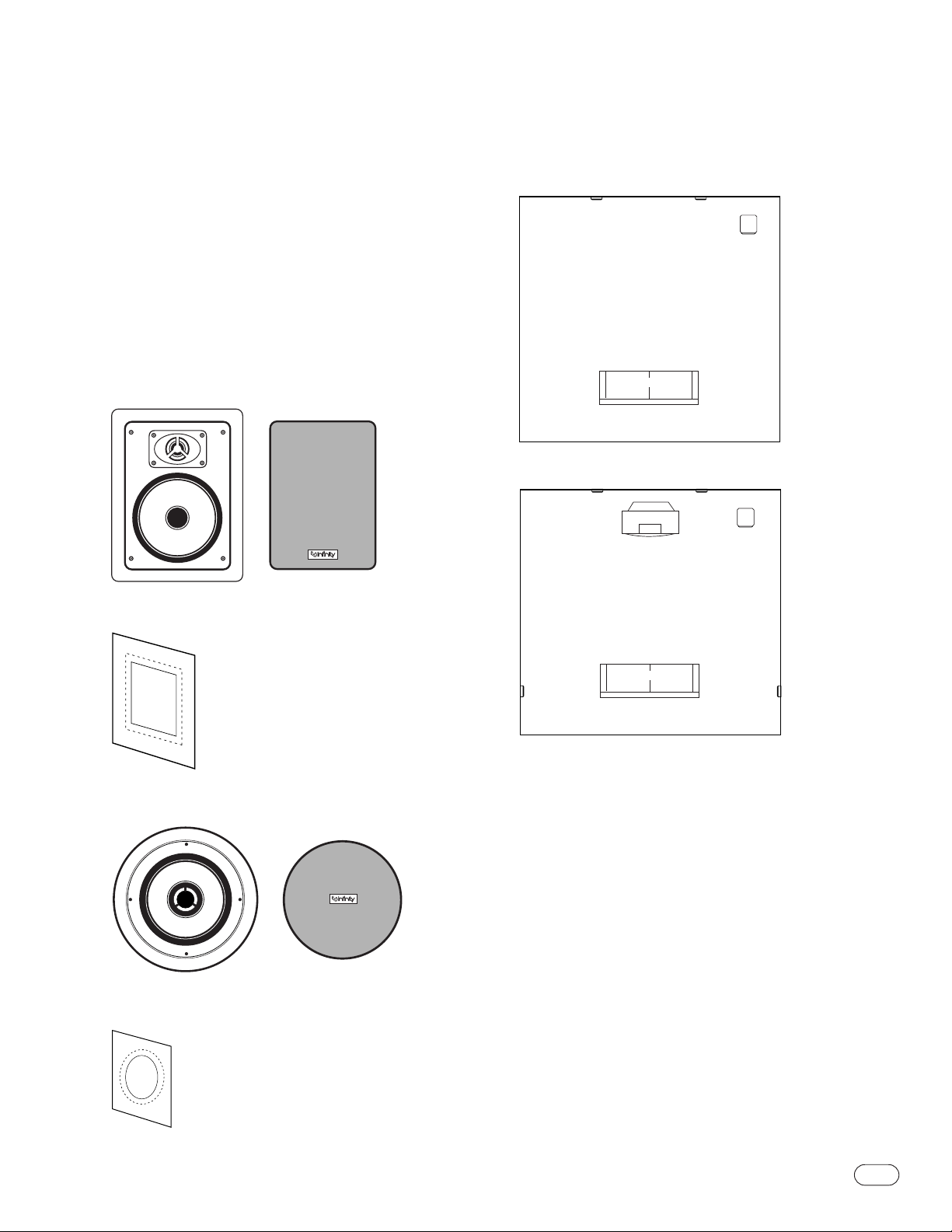
CS 50, CS 60
One speaker with grille and removable logo.
Template/paint shield.
Remove paint shield (inner
rectangle) at perforation.
CS 60R/CS 60RDT/CS 80R
Couch
Figure 1.
Infinity Subwoofer
Right
Front
Channel
(optional)
Surround
Right
Channel
Left
Surround
Channel
Front
Channel
Left
Center
Channel
Couch
Figure 2. This overhead view shows a typical home theater plan.
NOTE: Figures 1 and 2 show recommended speaker locations.
You may also follow these general placement suggestions when
installing the speakers in the ceiling.
One speaker with grille and removable logo.
Template/paint shield.
Remove paint shield (inner circle)
at perforation.
®
®
CS SERIES
3
Page 4

PLACEMENT
Stereo
Before deciding where to place your CS Series speakers, survey
your room and think about placement, keeping the following
points in mind, and using Figure 1 as a guide:
• For best results, place the speakers 6'–8' apart.
• When installing in the wall,position each speaker so that the
tweeter is as close to ear level as practical.
• Refer to “Home Theater”below if you also plan to use the
speakers in a home theater system.
Home Theater
For front-channel use, place one speaker on the left and another
on the right along either side of the television.
A center channel speaker should go directly above or below the
television and can be an in-wall or freestanding center channel.
For surround channel use, install the speakers alongside the
listening position.
NOTE: An Infinity powered subwoofer will add impact and
realism to both music and film soundtracks.Contact your
Infinity dealer for recommendations on subwoofer models for
your application.
Proper placement of the speakers is an important step in
obtaining the most realistic soundstage possible.These
recommendations are for the optimum placement of the
loudspeakers. Use these placement recommendations as a guide.
Slight variations will not diminish your listening pleasure.
Ideally, the front speakers should be placed the same distance from
each other as they are from the listening position.
In a home theater configuration, the two surround speakers should be
placed perpendicular to the listening position. If that is not possible,
they may be placed in a wall/ceiling behind the listening position.
CS 60RDT
Model CS 60RDT has the ability to play two channels through one
loudspeaker, thanks to its dual-tweeter/dual-voice-coil construction.
Since the tweeters are close together,generally they should be
aimed away from each other for best coverage.
For two-channel (stereo) appli
remote room of a distributed audio system),install the CS 60RDT
speaker centrally in the ceiling for best stereo imaging,pivoting
the tweeters so that one points toward the left and the other toward
the right of the listening position.
The CS 60RDT may also be used to play the left and right surround
channels in a 5.1-channel home theater system, in which case it
should be mounted in the ceiling slightly behind the listening
position, centered from left to right and with the tweeters pointing
toward the left and right of the listening position, aimed slightly
downward. For 7.1-channel systems where it is desired to use two
CS 60RDT speakers, one to play both the left surround and
surround back channels and the other to play both the right
surround and surround back channels, mount each CS 60RDT
speaker in the ceiling, slightly behind the listening position, one
closer to the left side of the room and the other closer to the right
side.Aim the tweeters, on each speaker,away from each other,
toward the front and rear of the room.
cations (e.g., as a single speaker
in a
INSTALLATION
The CS Series in-wall speakers were designed to be easily
installed. However, if you are unsure of your ability to properly
install these loudspeakers, please contact your dealer or a
qualified installer.
Tools Needed
4
CS SERIES
Pencil
Measuring tape
Carpenter’s level
Phillips #2 screwdriver
Utility knife
Awl
Page 5

SPEAKER CONNECTIONS
Figure 3.
Wire Length Recommended Size
Up to 50 ft. 16-gauge
Up to 100 ft. 14-gauge
Greater than 100 ft. 12-gauge
Turn Off All Power
Before completing the installation, you must connect your
speakers to your system. First, turn off all audio-system power.
Use high-quality speaker wire to make your connections. Use at
least #16-gauge speaker wire with polarity coding. Heavier
gauge wire is recommended for larger distances. Consult the
chart above or your dealer for recommendations.The side
of the wire with a ridge or other coding is usually considered
positive polarity (i.e., +). Also, consult the owner’s manuals
that were included with your amplifier or receiver to confirm
connection procedures.
Observe polarities when making speaker connections, as shown
in Figure 3. Connect each + terminal on the back of the
amplifier or receiver to the respective + (red) terminal on each
speaker. Connect the – (black) terminals in the same way.
Important!
Do not reverse polarities (i.e., + to – or – to +) when making
connections. Doing so will cause poor imaging and diminished
bass response. Be certain that positive and negative wire strands
are completely isolated to avoid short circuits that may damage
your equipment.
CS SERIES
5
Page 6

EXISTING CONSTRUCTION
Template
CS 50, CS 60
1. Remove the grille from
the speaker frame.
≥1/2"
≥1/2"
3. NOTE: Always allow at least
one-half inch between a wall
stud and the speaker cutout or
the locking tabs will not be
able to swivel into place.
≥1/2"
2. Determine the correct
speaker location.
NOTE: Remove the inner
template, which is the paint
shield, at the perforation. Use
the outer template when cutting
the drywall.
4. Cut the drywall.
CS 60R, CS 60RDT,CS 80R
1. Remove the grille from the
speaker frame.
≥1/2"
≥1/2"
3. Determine the correct speaker
location.
NOTE: Always allow at least onehalf inch between a wall stud
and the speaker cutout, or the
locking tabs will not be able to
swivel into place.
≥1/2"
2. Determine the correct
speaker location.
NOTE: Remove the inner
template, which is the paint
shield, at the perforation. Use
the outer template when
cutting the drywall.
4. Cut the drywall.
5. Connect the speaker
wires to the speaker.
7. Screw down each of the
Phillips head screws.The
locking tabs will swivel into
place and secure the unit to the
rear surface of the drywall.
6
CS SERIES
6. Place the speaker
assembly in the wall.
8. Replace the metal grille.
5. Connect the speaker wires to
the speaker. Model CS 60RDT
requires two sets of speaker
wires, one for each channel.
7. Screw down each of the four
Phillips head screws.The
locking tabs will swivel into
place and secure the unit to
the rear surface of the drywall.
6. Place the frame
assembly in the wall.
8. Replace the metal grille.
Page 7

SPECIFICATIONS
CS 50 CS 60 CS 60R CS 60RDT CS 80R
Frequency Range 48Hz – 20kHz (±3dB) 45Hz – 20kHz (±3dB) 50Hz – 20kHz (±3dB) 50Hz – 20kHz (±3dB) 45Hz – 20kHz (±3dB)
45Hz (–10dB) 38Hz (–10dB) 40Hz (–10dB) 40Hz (–10dB) 32Hz (–10dB)
Recommended 10 – 75 watts 10 – 100 watts 10 – 100 watts 10 – 100 watts total 10 – 100 watts
Amplifier Power (50WPC)
Range
Sensitivity 87dB 88dB 88db 88dB, both 89dB
(2.83V @ 1 meter) channels driven
Nominal Impedance 8Ω 8Ω 8Ω 8Ω per input 8Ω
Crossover Frequency 2400Hz; 12dB/Octave 2,800Hz; 12dB/Octave 2,600Hz; 12dB/Octave 2,600Hz; 12dB/Octave 2,400Hz; 12dB/Octave
Low-Frequency 5-1/4" (130mm) 6-1/2" (165mm) 6-1/2" (165mm) 6-1/2" (165mm) 8" (200mm)
Driver
High-Frequency 1" (25mm) with 1" (25mm) with 1" (25mm) Dual 3/4" (19mm) 1" (25mm)
Driver(s) acoustical waveguide acoustical waveguide
External Dimensions 7-1/2" x 10" 8-1/2" x 11" 9-3/16" (Dia.) 9-3/16" (Dia.) 10-7/8" (Dia.)
(W x H) (191mm x 254mm) (216mm x 279mm) (233mm) (233mm) (275mm)
Mounting Cutout Size 6-1/8" x 8-11/16" 7-1/8" x 9-11/16" 7-7/8" (Dia.) 7-7/8" (Dia.) 9-1/2" (Dia.)
(W x H) (156mm x 221mm) (181mm x 246mm) (200mm) (200mm) (240mm)
Mounting Depth 3-3/4" (95mm) 3-7/8" (98mm) 4-1/4" (108mm) 4-1/4" (108mm) 4-1/4" (108mm)
Weight 3 lb (1.4kg) 5 lb (2.3kg) 4.5 lb (2.0kg) 4 lb (1.8kg) 5.6 lb (2.5kg)
Optional CS 50RIF IW6 RIF IW6R RIF IW6R RIF IW8R RIF
Preconstruction
Rough-In Frame
Infinity continually strives to update and improve existing products,as well as create new ones.
The specifications and construction details in this and related Infinity publications
are therefore subject to change without notice.
Declaration of Conformity
We, Harman Consumer Group International
2, route de Tours
72500 Chateau-du-Loir
France
declare in own responsibility that the products described in this
owner’s manual are in compliance with technical standards:
EN 61000-6-3:2001
EN 61000-6-1:2001
Robin Marshall
Harman Consumer Group International
Chateau-du-Loir, France 8/04
Page 8

© 2004 Harman International Industries, Incorporated
Infinity Systems, 250 Crossways Park Drive,Woodbury, NY 11797 USA 516.674.4INF (4463) www.infinitysystems.com
Infinity is a registered trademark of Harman International Industries, Incorporated.Part No. 170-0049
 Loading...