

Page 1
BassLink T
Powered Subwoofer System
SERVICE MANUAL
Infinity Syst ems, Inc.
250 Crossways Park Dr.
Woodbury, New York 11797 Rev0 7/2004
Page 2

- CONTENTS -
SPECIFICATIONS ………………………………….……..1
CONNECTIONS/APPLICATIONS……………………..…2
CONTROLS AND FUNCTIONS.……...……..…...…...…5
BASIC TROUBLESHOOTING..…….…….………………6
EXPLODED VIEW / PARTS LI ST…………………………7
DISASSEMBLY PROCEDURE………………………..…8
AMPLIFIER BLOCK DIAGRAM……………………….…9
ELECTRICAL PARTS LIST ……………………………. 10
P.C . B. DRAWINGS….…………………………………….14
IC/TRANSISTOR PINOUTS…………………………….. 19
SCHEMATICS……………………………………………..23
PACKING…………………………………………………..26
Basslink T Specifications
Outp ut Powe r (14.4V supply) : 250W RMS
Frequency respo nse : 20Hz – 120Hz
Maximum input signal: 4.0V
Maximum sensitivity: 50mV
Idle Current <800mA
Crossover Sl o pe 12dB per oct av e
Max Current Draw 26A
Bass Boost -6dB to +3dB @ 40Hz
Dimensions: 40 3/8 x 6 7/16 x 14 3/8” (L x W x D)
(1026mm x 164mm x 366mm)
Fuse: 30A
Infinity continually strives to update and improve existing products, as well as create new ones. The specifications and details in
this and related JBL publications are therefore subject to change without notice.
1
Page 3
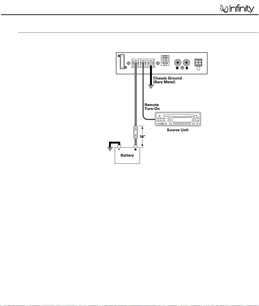
Connect power to BassLink T, as shown in
Figure 6. Also observe these installation tips:
•
Use at least #10 AWG wire for the +BATT
(+12 Vdc) and GND (ground) connections. If
needed, use at least a #20 AWG wire for the
REM (remote) connection.
•
Route all power wires through a grommet in
the vehicle’s firewall. If a factory grommet is
unavailable, install one.
•
Connect a short GND wire from BassLink T
to the nearest bare metal surface. For a
good connection, scrape away paint from
the metal surface and use a screw with a
lock (star) washer.
•
Install a fuse holder with a 25 A fuse within
18" of the battery’s positive (+) terminal (see
Figure 6).
•
The REM connection requires +5 to +12 Vdc
signal to turn on BassLink T. Most head units
with preamp outputs provide this remote
voltage signal. For speaker-level applications,
a remote connection is preferred but not
required, since BassLink T’s Auto Turn-On
feature will sense voltage on the speaker
wires to automatically turn on BassLink T.
IMPORTANT: To enable BassLink T’s Auto
Turn-On feature, set the AUTO TURN-ON
switch to the AUTO position (see Figure 12
on page 7).
Figure 6. Power connections for BassLink T.
POWER CONNECTIONS
BassLink T
(Control Panel)
Fuse 25 A
POWER
+BATT REM GND
FUSE
25A
REMOTE
LEVEL
CONTROL
LINE LEVEL
INPUT
HIGH LEVEL
INPUT
+
R
–
+
L
–
L R
BassLink T
2
Page 4
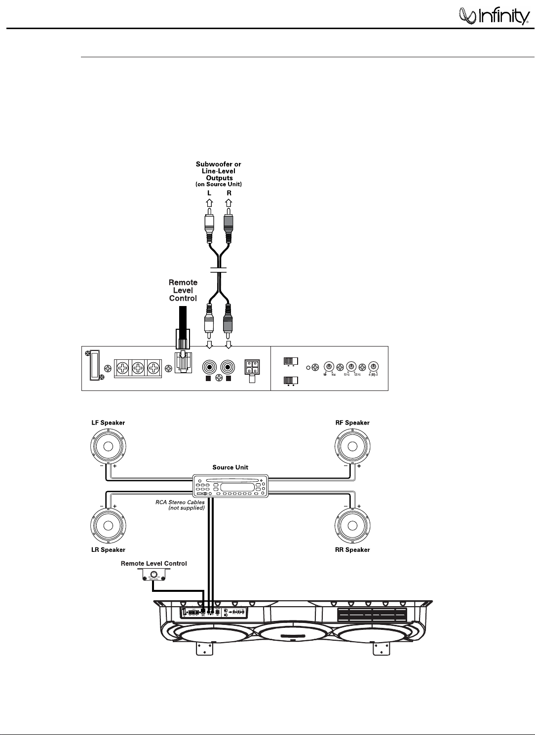
BassLink T is equipped with two line-level (RCA)
inputs and two speaker-level inputs.
To help you plan your installation, we have
included two system applications in Figures 7
and 8 on pages 4 and 5. For more system ideas,
see your authorized Infinity car audio dealer.
Figure 7. BassLink T audio connections for a head
unit with two line-level or subwoofer (RCA) outputs.
APPLICATIONS
POWER
+BATT REM GND
FUSE
25A
REMOTE
LEVEL
CONTROL
LINE LEVEL
INPUT
HIGH LEVEL
INPUT
AUTO
TURN ON
PHASE
GAIN CROSSOVER
BASS
BOOST
AUTOOFF
180°0°
+
R
–
+
L
–
L R
BassLink T
3
Page 5
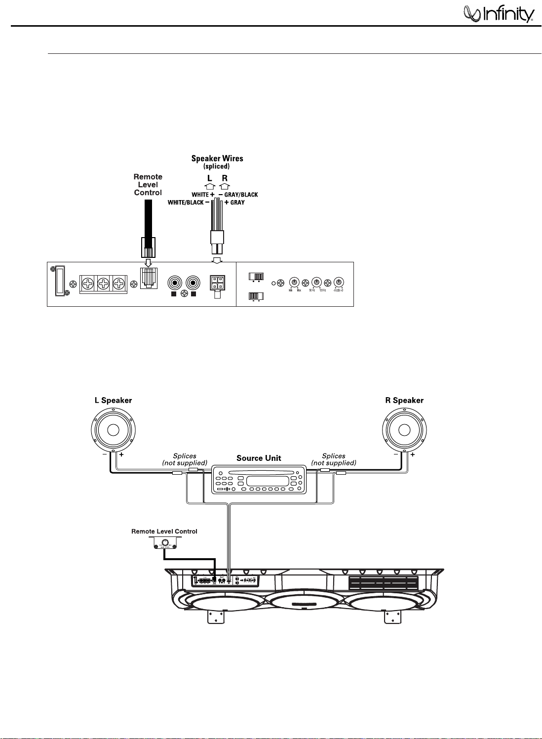
Figure 8. BassLink T audio connections for a head
unit equipped with two speaker-level outputs.
APPLICATIONS (CONTINUED)
POWER
+BATT REM GND
FUSE
25A
REMOTE
LEVEL
CONTROL
LINE LEVEL
INPUT
HIGH LEVEL
INPUT
AUTO
TURN ON
PHASE
GAIN CROSSOVER
BASS
BOOST
AUTOOFF
180°0°
+
R
–
+
L
–
L R
BassLink T
4
Page 6
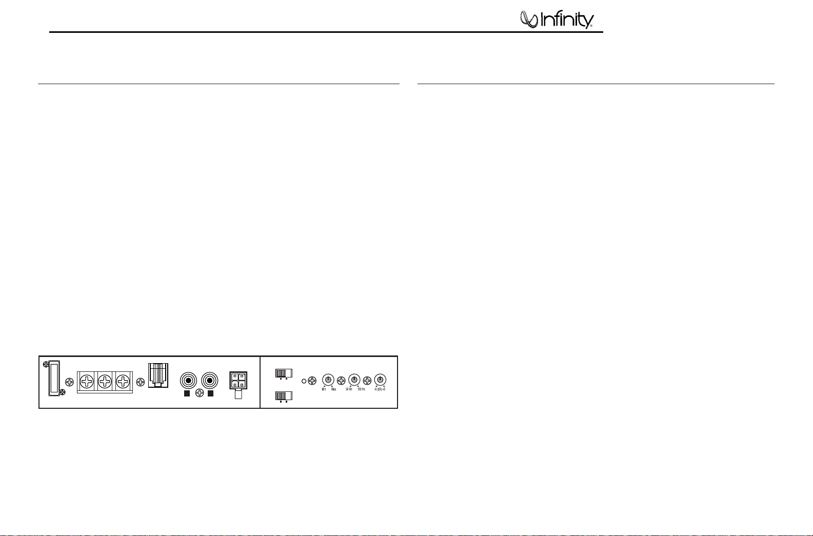
BassLink T provides several controls and indicators that simplify sonic integration with virtually
any vehicle’s unique acoustic properties. They are
located on the top control panel, as shown in
Figure 12.
GAIN Control: Use this control to adjust the
relative volume (loudness) of BassLink T with
respect to the other speakers in the vehicle.
CROSSOVER: Use this control to adjust the
amount of high-frequency information present in
BassLink T’s output. A lower value means more of
the high frequencies are filtered out.
BASS BOOST: Use this control to correct any
perceived peak or dip in the bass response
(typically around 40Hz in most vehicles). Set the
control to any value between –6dB and +3dB,
according to your preference.
PHASE Control: Use this switch to reverse the
phase of BassLink T’s output with respect to its
input. Choose the position (0° or 180°) that
sounds the best.
Figure 12. BassLink T control panel.
NOTE: Depending on BassLink T’s orientation and
location in a vehicle, reversing the phase may
(or may not) increase or decrease the amount
of perceived upper bass being reproduced.
AUTO TURN-ON: For speaker-level connections,
use this switch to activate (or deactivate)
BassLink T’s automatic turn-on circuit.
REMOTE LEVEL CONTROL: Use this RJ11 jack
to connect the Remote Level Control (see page 6).
PEAK LED:This indicator glows red when the
subwoofer is at maximum output. Be sure to
monitor this indicator during BassLink T setup
(see Tuning BassLink T). When properly tuned,
the PEAK LED should light momentarily during
high-level bass transients. Avoid adjustments
that cause the PEAK LED to remain lit for
extended periods.
POWER LED:This indicator will glow blue when
BassLink T is operational.
CONTROLS AND FUNCTIONS
1. Unplug the RJ11 cable that connects the
Remote Level Control to BassLink T.
2. Make sure the head unit is off and its volume
control is set to minimum.
3. On BassLink T’s top panel, initially set all
controls to their midpoint positions, as shown
in Figure 12. On BassLink T’s top panel,
initially set PHASE to 0°.
4. Turn on the head unit and play a favorite
music track that has substantial bass. Set the
head unit’s volume control to 75 percent of
the total output (approximately 3 o’clock on
rotary controls).
5. Adjust the GAIN control clockwise until the
PEAK LED (on BassLink T’s top panel) begins
to flash with each bass note but doesn’t stay
lit continuously.
6. Listen to your system, making a mental
note of the amount of upper bass being
reproduced.
7. S witch the PHASE control to 180° and listen
again for upper bass content. There may be
more upper bass, less upper bass, or no
change at all. The position that provides the
most upper bass is correct, but choose either
setting according to your taste.
8. Adjust the CROSSOVER control clockwise
or counterclockwise until you hear only lowfrequency information. For example, you
should NOT hear any vocals coming from
BassLink T when seated in the normal
listening position.
9. Adjust the BASS-BOOST control clockwise
or counterclockwise to suit your taste.
10.Recheck the PEAK LED to make sure it’s
flashing in time with the bass but is not lit
continuously. If it is lit continuously, adjust
the GAIN control counterclockwise until the
PEAK LED only flashes.
11.Reconnect the RJ11 cable between the Remote
Level Control and BassLink T. You may then
use the Remote Level Control to adjust the
level of the bass to suit your taste and/or
different program material.
NOTE: In most cases, the above steps will provide
satisfactory tuning. However, the actual process
may require several readjustments of each control,
since the settings will interact with each other.
If necessary, consult your authorized Infinity
car audio dealer for help in tuning your system.
TUNING BASSLINK T
BassLink T
5
LINE LEVEL
INPUT
L R
FUSE
25A
POWER
+BATT REM GND
REMOTE
LEVEL
CONTROL
HIGH LEVEL
INPUT
+
L
–
AUTO
TURN ON
+
R
–
PHASE
AUTOOFF
180°0°
PEAK
GAIN CROSSOVER
BASS
BOOST
Page 7

Capacitor
+ Speaker wire
from head unit
To + speaker-level
input on BassLink T
To + speaker lead
BassLink T
6
TROUBLESHOOTING
•
•
PROBLEM:
POWER LED is not lit.
CAUSES and SOLUTIONS:
1. Fuse is blown and needs replacement.
2. Head unit is not functioning properly. Check
remote voltage, and power, ground or remote
connections.
PROBLEM:
No output from BassLink T when head-unit
fader control is set to front or rear.
CAUSE and SOLUTION:
Input connections are improperly wired. Verify
all connections (see
Applications, starting on
page 4).
•
PROBLEM:
BassLink T produces a loud humming noise with
the system OFF when using speaker-level inputs.
CAUSE and SOLUTIONS:
This problem is caused by a feedback loop
between your speakers and the high-level inputs
of BassLink T.
•
PROBLEM:
POWER LED is lit but there is no bass.
CAUSES and SOLUTIONS:
1. Inputs are not connected. Check connections.
2. Head-unit fader control is not set properly.
Adjust head-unit fader control to feed audio
signals to BassLink T.
•
PROBLEM:
BassLink T sounds muddy or distorted.
CAUSES and SOLUTIONS:
1. Gain is set too high and PEAK LED is lit
constantly. Readjust GAIN control (see
Tuning BassLink T on page 7).
2. Bass is set too high. Readjust BASS BOOST
control (see Tuning BassLink T on page 7).
3. Head-unit output is distorted or blown. See
your authorized Infinity car audio dealer.
•
PROBLEM:
BassLink T turns on before head unit is
completely on and produces a “thump” sound.
CAUSE and SOLUTION:
For speaker-level connections, BassLink T is
receiving a false turn-on signal. On BassLink T’s
top panel, slide AUTO TURN-ON to OFF and use
the Remote (REM) connection.
•
PROBLEM:
BassLink T’s POWER LED remains on after head
unit is turned off.
CAUSE and SOLUTION:
For speaker-level connections, this is normal
operation when AUTO TURN-ON is set to ON.
BassLink T will remain on another 5 to 10 minutes
after sensing that audio signals are not present
before shutting down.
Choose one of the following solutions:
1. Connect a wire from the REMOTE terminal on
BassLink T to the remote turn-on of your head
unit or to the vehicle’s accessory circuit. On the
control panel, slide the AUTO-ON switch to the
OFF position.
2. Connect the supplied capacitors between each
of the speaker outputs of the head unit and
the speaker’s positive lead. Connect each
positive lead of BassLink T’s high-level inputs
to the head-unit side of the capacitors. Use
one capacitor per speaker input channel.
Figure 10. Connecting supplied capacitors.
Page 8
Basslink T
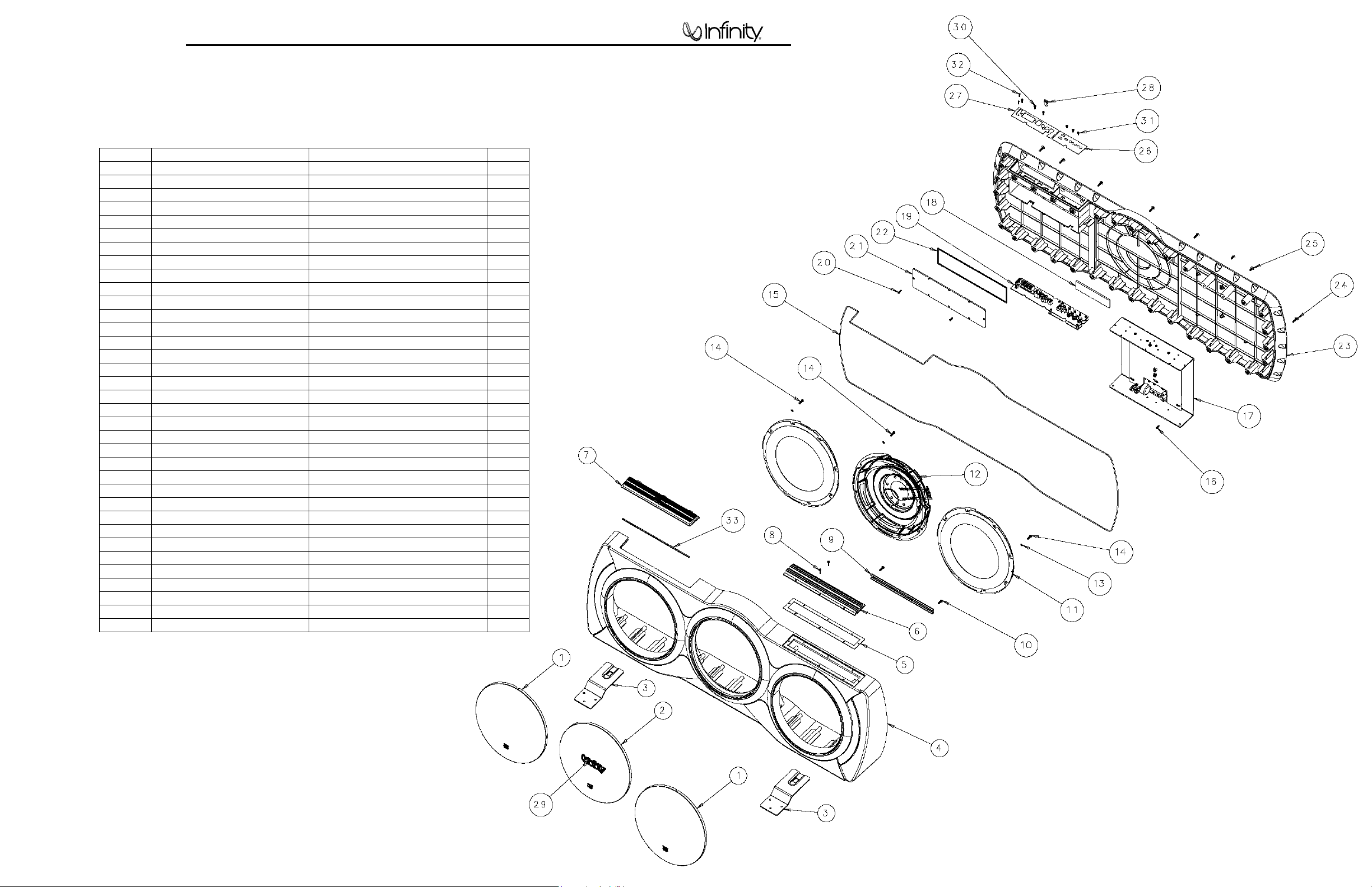
BASSLINK T EXPLODED VIEW
Ref # Part Number Description Qty
1 329-000-05012-0BA Front grille 2
2 329-100-05013-0BA Grille ass’y 1
3 321-FE-05006-0BA Bracket stand 2
4 243-100-05017-0BA Front cabinet 1
5 333-EVA-05024-0BA EVA gasket 1
6 323-AL-05016-0BA Heatsink extrusion 1
7 309-ABS-05005-0BA Control Cover Ass’y 1
8 352-DM3219C376 Screw 12
9 352-FE-05014-0LA U-bracket 1
10 352-AM04014C326 Screw 2
11 PR-255007 10” passive driver 2
12 F25X12PR-01DW 10” woofer 1
13 355-L06025 Spring washer m4 24
14 352-AM04014C326 Screw 4*14 24
15 336-EVA-05045-0BA EVA gasket 2
16 352-AM03010D065 Screw 6
17 011-7525-00488 Trunk sub amp 1
18 333-EVA-05026-0BA EVA gasket 1
19 051-B00488B Jack tone pcb ass’y 1
20 352-GM03010F055 Screw 8
21 309-ABS-05002-0BA Sealing cover ass’y 1
22 333-EVA-05023-0BA EVA gasket 1
23 247-100-05011-0BA Rear cover 1
24 352-HM04016B190 Screw 34
25 351-HM04010A217 Machine screw 2
26 315-PC-05019-0TA PC trim plate 1
27 315-PC-05020-0TA PC trim plate 1
28 327-010-05000-0BA Door latch 1
29 316-ABS-05006-0BA Infinity logo 1
30 352-AM03010D065 Screw 3
31 351-AM03008A079 Machine screw 3
32 352-AM02010D006 Screw 2
33 333-EVA-05021-0BA EVA gasket 1
7
Page 9
BassLink T
8
DISASSEMBLY PROCEDURE FOR BASSLINK T (ACCESS TO AMPLIFER, DRIVERS)
1) On a protected work surface, stand the unit up so the back panel is facing you.
2) Remove the (12) Phillips screws holding the b lack heatsink to the enclosure. Do not remove the
heatsink at this time.
3) Remove the (36) Phillips screws holding the back panel to the ma in enclosure. Note in the area of the
heatsink, two screws are shorter, machine screws.
4) Carefull y separate th e bac k pa nel from the mai n encl osure; try not to damage the O-r i ng th at m ay be
adhered to both sides of the enclosure, preventing its separation. Note the LED wires from the
heatsink area routed to the amplifier; unplug the 2 lead connection at female connector M2 on the
amplifier. Set the heatsink and LED w/ wires aside.
5) Unplug the woofer wires from the terminals.
6) Completely separate the two enclosure halves.
SERVICING THE INPUT/PREAMP SECTION
7) Remove the (8) Phillips screws holding the cover plate to the enclosure.
8) With a wood chisel or similar tool, carefully pry the plastic cover away from the cup, working around the
perimeter, until the cover is detached. If the cover is damaged during this procedure, order
part# 309-ABS-05002.
REASSEMBLY
9) If the cover to input/preamp section was detached, apply a bead of silicon sealer or similar adhesive
around the perimeter of the cover, in the sealing groove. Without this adhesive, there may be an air
leak which would affect performance. Press the cover into place.
10) Attach the woofer wires.
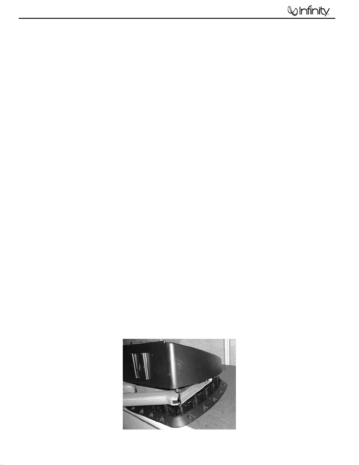
11) Before the enclosure can come together, connecting the heatsink/LED wire presents a challenge if not
correctly done. The LED wire must thread through the enclosure, the small hole in the aluminum
heatsink plate, and back into the M2 connector on the amplifier. The position in which this is best
achieved is with Basslink T laying flat side down on a surface, woofer side up. Partially bring the
enclosure halves together, and work through the remaining gap near the heatsink end. See illustration .
12) Make sure the O-ring around the perimeter of the enclosure is intact and in place. Make sure the two
shorter machine screws are used in the back panel, in the area near the heatsink.
13) Replace all enclosure and heatsink screws.
Page 10

BassLink T
9
Page 11

BassLink T
10
BASSLINK T Electrical Parts List
Part Numbers Description Reference Designators
POWER SUPPLY/AMPLIFIER PCB
Resistors
110-12102j52 resistor 1K 1/2W ±5% 52mm RX1
110-14000j26 resistor 0Ω 1/4W ±5% 26mm R525,530
110-16000j26 resistor 0Ω 1/6W ±5% 26mm D603
110-16100j26 resistor 10Ω 1/6W ±5% 26mm R521,523,613,500
110-16102j26 resistor 1K 1/6W ±5% 26mm R519,541,542,502,560,629,605
110-16103j26 resistor 10K 1/6W ±5% 26mm
110-16104j26
110-16105j26
110-16106j26
110-16122j26
110-16123j26
110-16152j26
110-16154j26
110-16182j26
110-16183j26
110-16204j26
110-16220j26 resistor 22Ω 1/6W ±5% 26mm R526,527,528,529
110-16221j26 resistor 220Ω 1/6W ±5% 26mm R76A,424,501
110-16222j26 resistor 2.2K 1/6W ±5% 26mm R228,515
110-16223j26 resistor 22K 1/6W ±5% 26mm R254,287,628,602
110-16333j26 resistor 33K 1/6W ±5% 26mm R277,614
110-16393j26 resistor 39K 1/6W ±5% 26mm R631
110-16432j26 resistor 4.3K 1/6W ±5% 26mm R505
110-16433j26 resistor 43K 1/6W ±5% 26mm R503
110-16471j26 resistor 470Ω 1/6W ±5% 26mm R510,522,524
110-16472j26 resistor 4.7K 1/6W ±5% 26mm R275,276,520
110-16473j26 resistor 47K 1/6W ±5% 26mm R77A,257,273,290,14A
110-16474j26 resistor 470K 1/6W ±5% 26mm R278
110-16511j26 resistor 510Ω 1/6W ±5% 26mm R256,286
110-16512j26 resistor 5.1K 1/6W ±5% 26mm R514
110-16562j26 resistor 5.6K 1/6W ±5% 26mm R238,518,630
110-16681j26 resistor 680Ω 1/6W ±5% 26mm R504,509
110-16682j26 resistor 6.8K 1/6W ±5% 26mm R516,77C
110-16755j26 resistor 7.5M 1/6W ±5% 26mm R293
116-141r00j26x metal film resistor 1.00Ω 1/4W ± 5% MO 26mm R615
116-142201j26x metal film resistor 2.2K 1/4W ± 5% MO 26mm R532,534
116-161132f26 metal film resistor 11.3K 1/6W ± 1% MO 26mm R512
116-167871f26 metal film resistor 7.87K 1/6W ± 1% MF 26mm R279
113-50r22j2z cement resistor 0.22Ω 5W ±5% R81A,82A
116-301000j52x metal film resistor 100Ω 3W ± 5% 52mm R539
116-303300jk2x metal film resistor 330Ω 3W 5% 10mm R531,533
resistor 100K 1/6W ±5% 26mm
resistor 1M 1/6W ±5% 26mm
resistor 10M 1/6W ±5% 26mm
resistor 1.2K 1/6W ±5% 26mm
resistor 12K 1/6W ±5% 26mm
resistor 1.5K 1/6W ±5% 26mm
resistor 150K 1/6W ±5% 26mm
resistor 1.8K 1/6W ±5% 26mm
resistor 18K 1/6W ±5% 26mm
resistor 200K 1/6W ±5% 26mm
R285,294,508511,540,611,507,612,616,621,622,623,
625,626,627,600,601,604,606
R517,618,624,603
R422,420
R421
R295
R234,513
R550
R80A
R74A
R274
R237
Capacitors
130-2b101k503 disc capacitor 100P 50V ± 10% C214,253,CM1,CM2,CM3,CM4
130-2b221mj03 disc capacitor 220P 1000V ± 20% C539
130-2f104z503 disc capacitor 0.1U 50V +80/-20%
130-3f222k503
132-102ja03 mylar capacitor 0.001uF 100V ±5% C62A,62B 420
132-103j503 mylar capacitor 0.001uF 100V ±5% C252,270,271
132-103ja03 mylar capacitor 0.01uF 100V ±5% C67
132-104ja03 mylar capacitor 0.1uF 100V ±5% C10A,10B,522,524,526,528,537,538,600
132-273ja03 mylar capacitor 0.027uF 100V ±5% C60A,66A66B
132-472j503 mylar capacitor 0.047uF 50V ±5% C507
135-3106m50 electrolytic 10uF 50V ±20% C272,273
135-3226m50 electrolytic 22U 50V ±20% C264,508
135-3227m25 electrolytic 220U 25V ±20% C504
135-3335m50 electrolytic 3.3uF 50V ±20% C601
135-3337m16 electrolytic 330uF 50V ±20% C612,622
135-3476m50 electrolytic 47uF 50V ±20% C421,422,251,531,532,534,536
disc capacitor 0.022uF 50V ± 10%
C268,269,502,503,506,509,510,511,512,533,535,540,
611,621,623,624,625
CX5
Page 12

A
BassLink T
11
Part Numbers Description Reference Designators
POWER SUPPLY/AMPLIFIER PCB
135-b227m35 electrolytic 220uF 35V ±20% 105 C502A
136-3336m50 non-polar capacitor NP 85 33uF 50V CX4
129-a105j633 metalize 1uF 63V ± 5% MSC C505
132-334j504 mylar capacitor 0.33U 50V ± 5% C500,501A
138-5108m801 electrolutic 1000uF 80 ± 20% ψ20*25 C521,523
138-5228m801 electrolutic 2200uF 80 ± 20% ψ25*30 C525,527
138-6338m351 electrolutic 3300uF 35 ± 20% ψ25*25 C501
Semiconductors
192-027c1815gr transistor 2SC1815GR NPN
192-027c2235y
192-028a1015gr
192-028a965y
197-031n4148 diode 100mA 75V SIGNAL 1N4148 ROHM D201,202,503,550,552,611,612,613,601,52A
199-05001505j zener diode 500mW 15V ROHM 52mm 1N5245B Z501,502
199-15000625 zener diode 6.2V 12W 52mm Z500
190-13494cn IC TL494CN PWM U500
190-16tl074cn IC TL074CN ST QUAD OP-AMP U203
190-99pc817c IC PC817C OPTOCOUPLER U501
192-027c1815gr transistor 2SC1815GR NPN Q200
192-161tip31c transistor TIP31C SGS NPN Q531
192-162tip32c transistor TIP32C SGS PNP Q532
192-16360nf06 transistor STP60NF06 SGS FET Q508,509,510,511
195-10204ubd LED 204-10UBD LD500
197-141n4004 diode 1N4004 D50
197-301604gd diode SF1604G-D D511,512
197-30sf16 diode SF16 D600
Miscellaneous
109-1ttc802j0 thermister TTC-802(js) NTC TH1
120-1000003 inductor 10W AI YT-C3104-005 1CRHW 354708LTB B500,501,502
122-11350j200 inductor R10*38 35uF ψ 2.0 L501
122-14106m130 inductor MIZI R251510 3*ψ 1.3 1.0mH L500
123-11k5arh06 inductor BEAD CORE-TECh K5A RH 3.5*1.6*6 Q508,509,510,511
150-r36231504 power transformer RT36-6T:28T T500
162-5002d001 wire 20mm 2PIN
162-5002d002 wire 20mm 3PIN
162-50122004 wire 120mm RED/WHT 2PIN
171-u845h2ac relay 845H-2A-C 12VDC RL50
175-1c02v01 wire connector 2PIN PITCH=2.5mm M2
175-1c08v01 wire connector 8PIN PITCH=2.5mm M1
176-ft205 wire connector FASTON M#205 S+,176-trpcb1m4 wire connector PCB1M4 BAT+,162-5045d002 WIRE RED UL1015 450mm RED/BLK #205T0.8 #250/110 T0.5
193-0s4211 insulator 42*11 CLASS-D-1
193-201612tr insulator T0-220 16mm*12mm
193-201815t2
193-2m1813 insulator T0-220 18*13mm Q508,509,510,511,531,532,D511,D512
236-AL-05001
323-AL-05013-0LA HEAT SINK 250*240*61*3T SILVER
333-SPG-05036-0BA SPONGE 500*50*5T
351-AM03005A015 SCREW M3*0.5P*5L BLK TO PCB/CU HOLDER-6
351-AM03006A069 SCREW M3*6 BLK
351-AM03007A368 SCREW M3*7 BLK TO H-S/CU HOLDER-6
351-AM03008A079 SCREW M3*8 BLK CONTROL PCB TO NYL SPACE-4
351-AM03012A090 SCREW M3*12 BLK IC-HOLDER-1
351-AM03018A364 SCREW M3*18 BLK CLASS-D-2
351-BM03014A093 SCREW M3*14 BLK HEAT SINK TO IC HOLDER-4
351-FM04006A220 SCREW M4*6 NI
355-P0407236 SPRING WASHER M4 ID4.2* OD7.0*T1.0
361-FE-05000 IC HOLDER 69*12*4*1.5T
361-FE-05003-0LA IC HOLDER 25*12*4*1.5T TO IC-1
362-CU-05004-0YA CU SPACER M3*8H
362-CU-05010 CU SPACER M3*11.8H
transistor 2SC2235Y NPN
transistor 2SA1015GR PNP
transistor 2SA965Y PNP
insulator
L holder
Q201,404,405,406,501,503,513,514,601,610,611,612
,622,624, 626
Q16A
Q502,504,505,506,621,623,625,202,602
Q500
Page 13

X
BassLink T
12
Part Numbers Description Reference Designators
INPUT/PREAMP PCB
362-NYL-05006-0WA HOLDER(NYLON)10H(MAE-10T;HAKUTO-10)WHT
Resistors
110-16102j26
110-16103j26
110-16104j26 resistor 100K 1/6W ±5% CF 26mm R301,36
110-16123j26
110-16151j26
110-16153j26
110-16154j26
110-16204j26
110-16222j26
110-16223j26
110-16243j26 resistor 24K 1/6W ±5% CF 26mm R225
110-16302j26
110-16303j26
110-16333j26
110-16392j26
110-16393j26
110-16472j26
110-16474j26
110-16511j26
110-16513j26
110-16683j26
110-16752j26
129-a104j633 metalize 0.1U 63V ± 5% MSC C211
129-a224j633
129-a823j633 metalize 0.082U 63V ± 5% MSC C216
115-v503b103
115-v503b204
Capacitors
resistor 1K 1/6W ±5% CF 26mm
resistor 10K 1/6W ±5% CF 26mm
resistor 12K 1/6W ±5% CF 26mm
resistor 150Ω 1/6W ±5% CF 26mm
resistor 15K 1/6W ±5% CF 26mm
resistor 150K 1/6W ±5% CF 26mm
resistor 200K 1/6W ±5% CF 26mm
resistor 2.2K 1/6W ±5% CF 26mm
resistor 22K 1/6W ±5% CF 26mm
resistor 3K 1/6W ±5% CF 26mm
resistor 30K 1/6W ±5% CF 26mm
resistor 33K 1/6W ±5% CF 26mm
resistor 3.9K 1/6W ±5% CF 26mm
resistor 39K 1/6W ±5% CF 26mm
resistor 4.7K 1/6W ±5% CF 26mm
resistor 470K 1/6W ±5% CF 26mm
resistor 510Ω1/6W ±5% CF 26mm
resistor 51K 1/6W ±5% CF 26mm
resistor 68K 1/6W ±5% CF 26mm
resistor 7.5K 1/6W ±5% CF 26mm
metalize 0.22uF 63V ± 5% MSC
variable resistor RV09AC-40-30K-B50K
variable resistor RV09A02-40-30K-B50K
R219,222,233
R229,23,24,302,307,309,312,330,5,6
R227
R311,310
R252,218,328,304
R329
R27,28,29,30
R37,38,39,40
R240,241,250
R200
R305
R253
R224
R223
R1,2,19,20
R220
R303,306
R10,11,12,9,17,18
R251
R221
C215,260,261,262,263,210
VR201,202
VR203
130-2b101k503 disc capacitor 100P 50V ± 10% C242,CW1,CW2,CW3,CW4,CW5,C11,12
130-2b102k503 disc capacitor 1000P 50V ± 10% CX1
130-2b221k503 disc capacitor 220P 50V ± 10% C3,4
130-2f104z503 disc capacitor 0.1U 50V +80/-20% C229,231,233,234,235,274,301,303,5,6,CX2
132-103j503 mylar capacitor 0.01U 50V ± 5% C217,13
135-3105m50
135-3106m50
135-3475m50
137-3106m50
137-3226m50
135-0108m25 electolytic 1000U 25V ± 20% CX3
137-3226m50
Semiconductors
192-027c1815gr transistor 2SC1815GR NPN Q301
197-031n4148 diode 100mA 75V SIGNAL 1N4148 ROHM D1,2
190-06m13700n
190-06m45581
195-10204hd
197-306a20
Miscellaneous
154-1025a800
155-9f30240
162-50048002
162-80098001
162-80659001
162-a0802001
174-020123bg RCA PIN JACK JK020123BG JK1
174-535913sg
174-9mjd0604
175-9h04v01
electolytic 1U 50V ± 20%
electolytic 10uF 50V ± 20%
electolytic 4.7U 50V ± 20%
electolytic 10uF 50V ± 20%
electolytic 22uF 50V ± 20%
electolytic 22uF 50V ± 20% 85
IC NJM13700N JRC DUAL OP-AMP
IC NJRC NJM4558LD DUAL OP-AMP
LED 3mm FOR STANDBY
diode 6A 200V 6A20
fuse 25A 32V ATC UL/CSA
fuse holder F30240100P
wire 45mm 9PIN PITCH=2.5mm
wire 90mm 26AWG
wire 650mm
wire UL1015 12AWG 800mm RED/BLK
DC JACK SL035913SG
M/JACK D/S 6P4C 6U"
wire connector 4PIN PITCH=4.2mm
C311
C228,230,300,302
C312
C7,8,9,266,267
C2
C1
U301
U1,200,204,205
LED1
DXX
F500
W2
W1
JK500
JK4
JK2
Page 14

BassLink T
13
Part Numbers Description Reference Designators
CLASS-D 300 ASS'Y
180-s570050
359-FIB-00001 fiber washer ψ12*1.5 adhesive
362-NYL-05005-0WA LED spacer(nylon) ψ4*10.5H LED1
Resistors
118-12061001j
118-12061002j
118-120610r0j SMD resistor 10.0Ω1206 5% R20,20B,22,23
118-12062002j
118-12062201j
118-12062204j
118-12062701j
118-12063000j
118-12063301j
118-12063902j
118-12064700j SMD resistor 470Ω1206 5% R8,11,21
118-12064701j
141-c0101k50
141-c0220k50
141-c0561k50
141-c5104m50
141-c7223k50
141-d7104ka0
Capacitors
132-104kb04a mylar capacitor 0.1uF 200V ± 10% PITCH 10mm C20
132-105kb50 mylar capacitor 1uF 250V ± 10% C40
switch SS70050-0202-10T-NN
SMD resistor 1.00K 1206 5%
SMD resistor 10.0K 1206 5%
SMD resistor 20.0K 1206 5%
SMD resistor 2.20K 1206 5%
SMD resistor 2.20M 1206 5%
SMD resistor 2.70K 1206 5%
SMD resistor 300.0Ω1206 5%
SMD resistor 3.3K 1206 5%
SMD resistor 39.0K 1206 5%
SMD resistor 4.7K 1206 5%
SMD capacitor 100pF 50V 10%1206 NP0
SMD capacitor 22pF 50V 10%1206 SMT NP0
SMD capacitor 560pF 50V 10%1206 NPO
SMD capacitor 1206 Y5V 0.1uF 50V ± 20%
SMD capacitor 0.022uF 50V 10% 1206 X7R
SMD capacitor 0.1uF 100V 10% 1210 X7R
SW1,2
R2
R25,29,30,30B,7,9
R26
R6,13,16,31,33,34,35,36,37,38,39,40,41,42,43,44,45,
46,32
R4
R10
R24
R1,14,15,27,28
R3
R5,12
C4
C5
C6
C2,3,7,8,9,10,11,15
C13
C12,14,18,19
Semiconductors
190-16tl072dts
192-09124126qs
192-09139066rs
192-091sc4672
192-09210376qs
192-09215146rs SMD transistor 2SA1514K-T146R ROHM Q3
192-1682n5401
197-03rls4148s SMD diode RLS4148-TE11 ROHM D1,2,3,4,5,5B,6,20
199-15000563s SMD ZENER 5.6V 5% PHILIPS BAX84-CV6 Z1,2
199-15001203s SMD ZENER 12V 5% PHILIPS BAX84-C12 Z3,4,5,6
192-232irf9640
192-233irf640
122-13151k0190 inductor CHOKE SA-500-280 L1
122-14300k4 inductor ferrite core LD1215*300KU ± 10% L2
Capacitors
128-e106ma01-s
132-104kb04a mylar capacitor 0.1uF 200V ± 10% PITCH 10mm C20
132-105kb50 mylar capacitor 1uF 250V ± 10% C40
IC TL072CDT SGS THOMSON DUAL OP-AMP
SMD transistor 2SC2412K-T1460/R ROHM
SMD transistor 2SC3906K-T146R ROHM
SMD transistor 2SC4672 ROHM
SMD transistor 2SA1037K-T146Q/R ROHM
Transistor 2N5401 AI-PNP 350V 500mA T0-92
transistor IRF9640 IR P-CH TO220 MOSFET
transistor IRF640 IR N-CH TO-220 MOSFET
non-polar electrolytic 10uF 100V 20%
IC1
Q1,4
Q2,8
Q5B
Q7,9
Q6B
Q10,10B
Q11
C16,17
Page 15

BassLink T
14
Page 16

BassLink T
15
Page 17

BassLink T
16
Page 18

BassLink T
17
Page 19

BassLink T
18
Page 20

BassLink T
19
BASSLINK T IC PINOUTS
NJM137000N PINOUTS
1.Amp Bias Input A 9.Buffer Output B
2.Diode Bias A 10.Buffer Input B
3.+ Input 11.V+
4.- Input 12.Output B
5.Output A 13.-Input B
6.V- 14.+Input B
7.Buffer Input A 15.Diode Bias B
8.Buffer Output A 16.Amp Bias Input B
NJM4558L PINOUTS
1.A Output 5.B +Input
2.A -Input 6.B -Input
3.A +Input 7.B Output
4.V- 8.V+
TL494 PINOUTS
1.Err Amp 1 In+ 9. E1
2.Err Amp 1 In- 10. E2
3.Feedback 11. C2
4.Dead-Time Ctrl 12. Vcc
5.Ct 13. Output Ctrl
6.Rt 14. Ref
7.Gnd 15. Err Amp 2 In-
8.C1 16. Err Amp 2 In+
Page 21

BassLink T
20
TL07 4
TL074A - TL074B
LOW NOISE J-FET QUAD OPERATIONAL AMPLIFIERS
.WIDE COMMON-MODE (UP TO V
DIFFERENTIALVOLTAGERANGE
CC
+
)AND
.LOW INPUT BIASANDOFFSETCURRENT
.LOW NOISE e
=15nV/√Hz(typ)
n
.OUTPUTSHORT-CIRCUIT PROTECTION
.HIGH INPUT IMPEDANCE J–FET INPUT
STAGE
.LOW HARMONIC DISTORTION:0.01%(typ)
.INTERNALFREQUENCYCOMPENSATION
.LATCHUPFREE OPERATION
.HIGHSLEWRATE : 13V/µs(typ)
DESC RIP TI ON
The TL074,TL074Aand TL074Barehighspeed
J–FETinputquadoperation alamplifiersincorporating
wellmatched,high voltageJ–F ETand bipolartransistorsin amonolithicintegratedcircuit.
Thedevicesfeaturehighslewrates,lowinputbiasand
offsetcurrents,and lowoffsetvoltagetemperatur e
coefficient .
(PlasticPackage)
(PlasticMicropackage)
ORDER CODES
Part Number
TL074M/AM/BM –55
TL074I/AI/BI –40
TL074C/AC/BC 0
Example : TL074IN
N
DIP14
D
SO14
Temperature
Range
o
C, +125oC ••
o
C, +105oC ••
o
C, +70oC ••
Package
ND
PIN CONNECTIO NS (topview)
Output 1
Inverting Input 1
Non-inverting Input 1
V
Non-inverting Input 2
Inverting Input 2
Output 2
October1997
CC
14
1
2
-
+
3
+
4
5
+
-
6
7
-
+
+
-
Output 4
13
Inverting Input 4
12
Non-inverting Input 4
11
10
9
8
-
V
CC
Non-inverting Input 3
Inverting Input 3
Output 3
1/10
Page 22

BassLink T
21
BASSLINK T TRANSISTOR PINOUTS
PARTS NAME
1 2 3
IRF9640 Gate Drain Source
IRF640 Gate Drain Source
STP60NF06 Gate Drain Source
PARTS NAME
1 2 3
TIP31C base Collector Emiter
TIP32C base Collector Emiter
PINOUTS
PINOUTS
PARTS NAME
1 2 3
2SA1015 Emiter Collector base
2SA965 Emiter Collector base
2SC1815 Emiter Collector base
2SC2235 Emiter Collector base
2N5401 Emiter Base Collector
PINOUTS
Page 23

BassLink T
22
Page 24

BassLink T
23
Page 25

BassLink T
24
Page 26

BassLink T
25
Page 27

BassLink T
26
 Loading...