


SUPPLEMENTAL RESTRAINT SYSTEM (SRS)
H RESTRAINTS
A
B
SECTION
SUPPLEMENTAL RESTRAINT SYSTEM (SRS)
PRECAUTIONS .......................................................... 3
Precautions for Supplemental Rest raint System
(SRS) “AIR BAG” and “SEAT BELT PRE-TEN-
SIONER” .................................................................. 3
Precaution s for SRS “AI R BAG” and “SEAT BELT
PRE-TENSIONER” Service ..................................... 3
Trouble Diagnosis Precaution .................................. 3
PREPARATIO N ................. .................... ...................... 4
Special Service Tools ............................................... 4
Commercial Service Tools ........................................ 5
SUPPLEMENTAL RESTRAINT SYSTEM (SRS) ....... 6
SRS Configuration ................................................... 6
Front Seat Belt Pre-Tensioner With Load Limiter ..... 7
Front Side Air Bag .................................................... 7
Side Curtain Air Bag ................................................. 7
TROUBLE DIAGNOSIS .............................................. 8
Trouble Diagnoses Introduction ............................... 8
DIAGNOSIS FUNCTION ....................................... 8
HOW TO PERFORM TROUBLE DIAGNOSES
FOR QUICK AND ACCURATE REPAIR ............... 8
WORK FLOW ........................................................ 9
SRS Components Parts Location ........................... 10
Schematic ...............................................................11
Wiring Diagram-SRS- ............................................. 12
CONSULT-II Function ............................................ 18
DIAGNOSIS MODE FOR CONSULT-II ............... 18
HOW TO CHANGE SELF-DIAGNOSIS MODE
WITH CONSULT-II .............................................. 18
HOW TO ERASE SELF-DIAGNOSIS RESU LTS ... 19
Self-Diagnosis Function (Without CONSULT-II) ..... 20
HOW TO CHANGE SELF-DIAGNOSIS MODE ... 20
HOW TO ERASE SELF-DIAGNOSIS RESU LTS ... 20
SRS Operation Check ............................................ 20
DIAGNOSTIC PROCEDURE 1 ........................... 20
Trouble Diagnoses with CONSULT-II ..................... 22
DIAGNOSTIC PROCEDURE 2 ........................... 22
DIAGNOSTIC PROCEDURE 3 ........................... 26
DIAGNOSTIC PROCEDURE 4 (CONTINUED
FROM DIAGNOSTIC PROCEDURE 2) .............. 28
DIAGNOSTIC PROCEDURE 5 ........................... 28
CONTENTS
Trouble diagnoses without CONSULT-II. ................ 32
DIAGNOSTIC PROCEDURE 6 ...........................32
WARNING LAMP FLASH CODE CHART ...........33
Trouble Diagnoses: “AIR BAG” Warning Lamp Does
Not Turn Off ............................................................ 37
DIAGNOSTIC PROCEDURE 7 ...........................37
Trouble Diagnoses: “AIR BAG” Warning Lamp Does
Not Turn On ............................................................ 38
DIAGNOSTIC PROCEDURE 8 ...........................38
DRIVER AIR BAG MODULE .................................... 39
Removal and Installation ........................................ 39
REMOVAL ........................................................... 39
INSTALLATION ...................................................40
SPIRAL CABLE ........................................................ 42
Removal and Installation ........................................ 42
REMOVAL ........................................................... 42
INSTALLATION ...................................................43
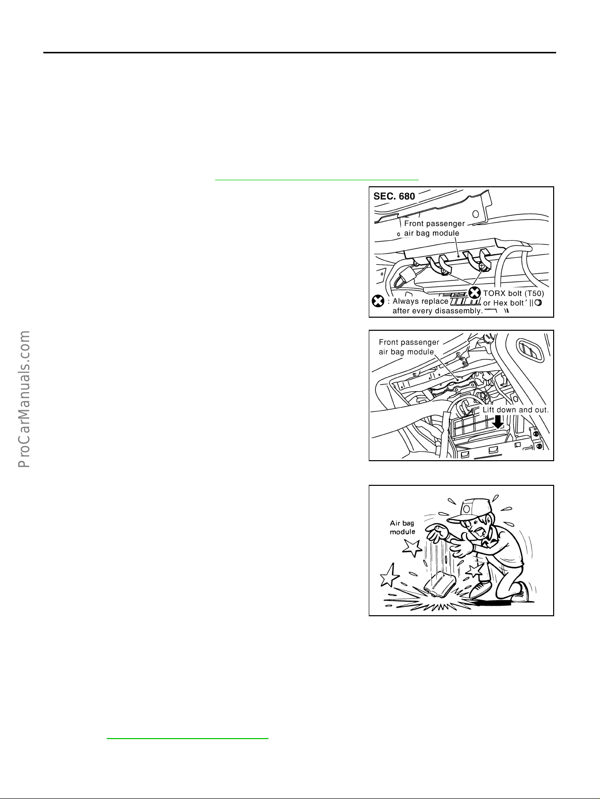
FRONT PASSENGER AIR BAG MODULE .............. 44
Removal and Installation ........................................ 44
REMOVAL ........................................................... 44
INSTALLATION ...................................................44
FRONT SIDE AIR BAG MODULE ............................ 45
Removal and Installation ........................................ 45
REMOVAL ........................................................... 45
INSTALLATION ...................................................46
SIDE CURTAIN AIR BAG MODULE ........................ 47
Removal and Installation ........................................ 47
REMOVAL ........................................................... 47
INSTALLATION ...................................................47
CRASH ZONE SENSOR ............. ...... ....... ...... ....... .... 48
Removal and Installation ........................................ 48
REMOVAL ........................................................... 48
INSTALLATION ...................................................48
SIDE AIR BAG (SATELLITE) SENSOR ................... 49
Removal and Installation ........................................ 49
REMOVAL ........................................................... 49
INSTALLATION ...................................................49
FRONT SEAT BELT PRE-TENSIONER ...................50
Removal and Installation ........................................ 50
C
D
E
F
G
SRS
I
J
K
L
M
Revision; 2004 April 2003 Q45
SRS-1

DIAGNOSIS SENSOR UNIT .....................................51
Removal and Installation ........................................51
REMOVAL ...........................................................51
INSTALLATIO N ............ ............. ............. .............. 51
ECU DISCRIMINATED NO. .................................51
DISPOSAL OF AIR BAG MODULE AND SEAT BELT
PRE-TENSIONER .....................................................52
Caution for Air Bag Module and Seat Belt Pre-Ten-
sioner ........................ ..............................................52
CHECKING DEPLOYMENT TOOL .....................52
DEPLOYMENT PROCEDURES FOR AIR BAG
MODULE (OUTSIDE OF VEHICLE) ...................53
DEPLOYMENT PROCEDURES FOR SEAT
BELT PRE-TENSIONER (OUTSIDE OF VEHI-
CLE) ....................................................................57
DEPLOYMENT OF AIR BAG MODULE AND
SEAT BELT PRE-TENSIONER WHILE
MOUNTED IN VEHICLE ......................................57
DISPOSING OF AIR BAG MODULE AND SEAT
BELT PRE-TENSIONER .................................. ....58
COLLISION DIAGNOSIS ..........................................59
For Frontal Collision ........................ ....... ...... ....... ....59
SRS INSPECTION (FOR FRONTAL COLLI-
SION) ........................ ...........................................59
For Side Collision ............... ....... ...... ....... ...... ....... ....60
WHEN THE SIDE AIR BAG IS ACTIVATED IN
THE SIDE COLLISION: .......................................60
WHEN SRS IS NOT ACTIV ATED IN THE SIDE
COLLISION: .................... ................................. ....61
SRS INSPECTION (FOR SIDE COLLISION) ......61
Revision; 2004 April 2003 Q45
SRS-2

PRECAUTIONS
PRECAUTIONS PFP:00001
Precautions for Supplemental Restraint System (SRS) “AIR BAG” and “SEAT BELT PRE-TENSIONER”
EHS000M8
A
The Supplemental Rest raint System such as “AIR BAG” and “SEAT BELT PRE-TENSIONER”, used al ong
with a front seat belt, helps to redu ce th e risk or se verit y of i njury to the driv er and front passenge r for ce rtain
types of collision. This system includes seat belt switch inputs and dual st age front air bag modules. The SRS
system uses the seat belt switches to determine the front air bag deployment, and may only deploy one front
air bag, depending on the severity of a collision and whether the front occupants are belted or unbelted.
Information necessary to service the system safely is included in the SRS and SB section of this Service Manual.
WARNING:
● To avoid rendering the SRS inopera tive, whi ch could incr ease the risk of pe rsonal injury or death
in the event of a collision which would result in air bag inflation, all maintenance must be performed by an authorized NISSAN/INFINITI dealer.
● Improper maintenance, inc luding incorrect removal and installation of the SRS, can lead to per-
sonal injury ca use d by unintentional ac tiv atio n o f the s ys tem . F or re moval of Spiral C ab le and A ir
Bag Module, see the SRS sec tion.
● Do not use electrical test equ ipment o n any circu it related to the SRS unless in structed to in this
Service Manual. SRS wiring harnesses can be identified by yellow and/or orange harnesses or
harness connectors.
Precautions for SRS “AIR BAG” and “SEAT BELT PRE-TENSIONER” Service
● Do not use electrical test equipment to check SRS circuits unless instructed to in this Service Manual.
● Before serv ic ing th e S RS , t ur n igni t io n s wit c h OF F, disconnect b oth ba tt e ry ca bl e s an d wai t at l ea st 3 m in -
utes.
For approximately 3 minutes after the cables are removed, it is still possible for the air bag and seat belt
pre-tensioner to deploy. Therefore, do not work on any SRS connectors or wires until at least 3 minutes
have passed.
● Diagnosis sensor unit must always be installed with their arrow marks “⇐” pointing towards the front of the
vehicle for proper operation. Also check diagnos is sensor unit for cr acks, deformities or rust before installation and replace as required.
● The spiral ca bl e must be aligned with the ne utra l p os ition since its rotatio ns a r e l im ite d. Do not attemp t to
turn steering wheel or column after removal of steering gear.
● Handle air bag module carefully. Always place driver and front passenger air bag modules with the pad
side facing upward and place front side air bag module standing with stud bolt side setting bottom.
● Conduct self-diagnosis to check entire SRS for proper function after replacing any components.
● After air bag inflates, the front instrument panel assembly should be replaced if damaged.
B
C
D
E
F
G
EHS0008B
SRS
I
J
K
L
Trouble Diagnosis Precaution EHS0009L
When you read wiring diagrams, refer to the followings:
● GI-14, "How to Read Wiring Diagrams" in GI section
● PG-2, "POWER SUPPLY ROUTING" in PG section
When you perform trouble diagnosis, refer to the followings:
● GI-10, "HOW TO FOLLOW TEST GROUPS IN TROUBLE DIAGNOSES" in GI section
● GI-26, "How to Perform Efficient Diagnosis for an Electrical Incident" in GI section
Check for any service bulletins before servicing the vehicle.
Revision; 2004 April 2003 Q45
SRS-3
M

PREPARATION
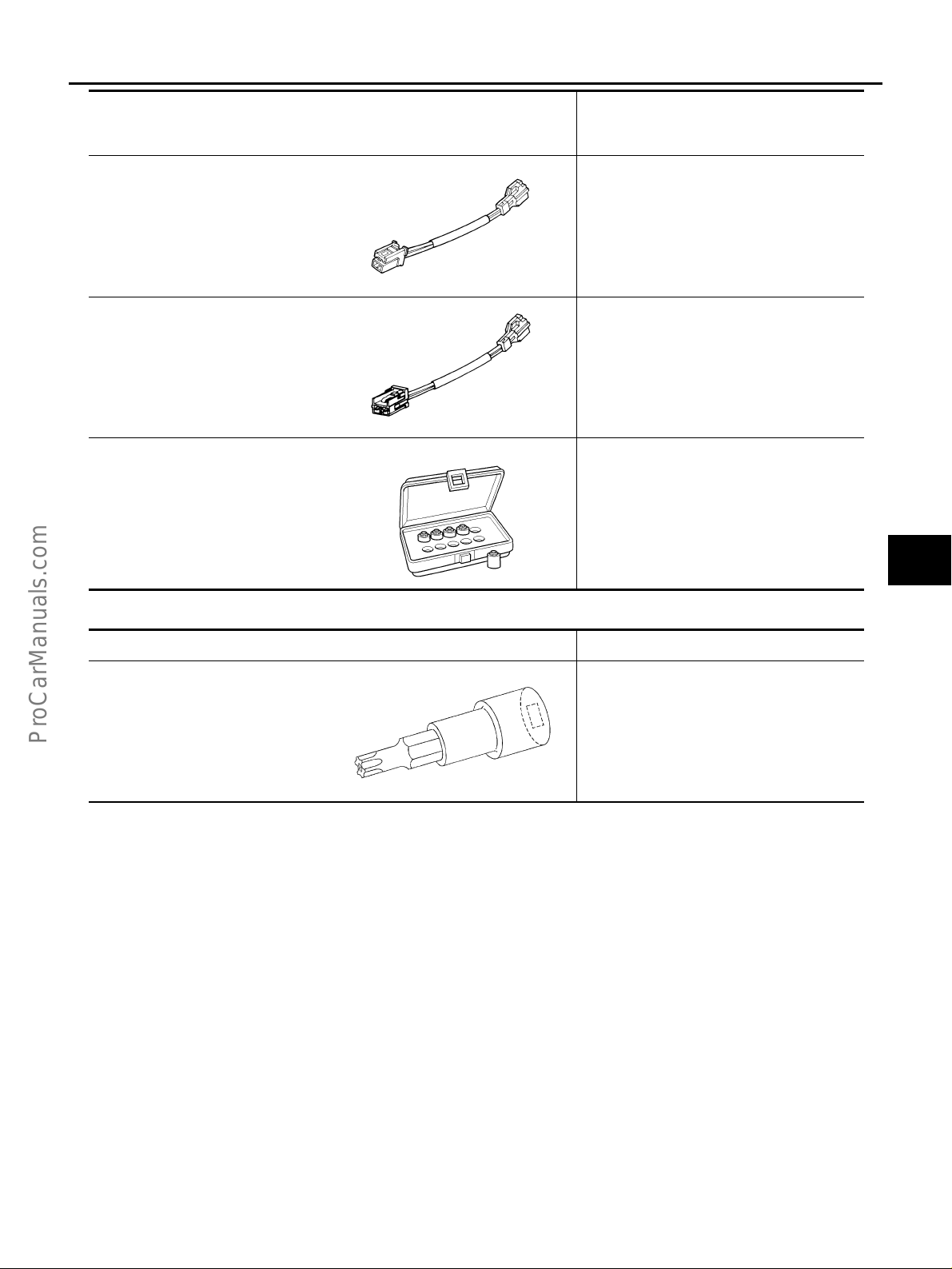
PREPARATION PFP:00002 Special Service Tools EHS0008C
The actual shapes of Kent-Moore tools may differ from those of special service tools illustrated here.
Tool number
(Kent-Moore No.)
Tool name
HT61961000 and HT62152000
combined
(J38219)
*Special torx bit
S-NT361
KV99105300
(J41246)
Air bag module bracket
S-NT354
Description
Use for special bolts [TAMPER
RESISTANT TORX (Size T50)]
a: 3.5 (0.138) dia.
b: 8.5 - 8.6 (0.335 - 0.339) dia.
c: approx. 10 (0.39) sq.
Unit: mm (in)
Anchoring air bag module
KV99106400
(J38381)
Deployment tool
(J38381-70)
Deployment tool adapter for driver
air bag module
(J38381-65)
Deployment tool adapter for front
passenger air bag
(J38381-80)
Deployment tool adapter for front
seat belt pre-tensioner (Yellow
connector)
Disposing of air bag module and front seat
belt pre-tensioner
S-NT357
Connection between the deployment tool
and driver air bag module
SHIA0172E
Connection between the deployment tool
and front passenger air bag module
SHIA0173E
Connection between the deployment tool
and front seat belt pre-tensioner
PHIA0184E
Revision; 2004 April 2003 Q45
SRS-4
PREPARATION
Tool number
(Kent-Moore No.)
Tool name
KV99109000
(J44230)
Deployment tool adapters for side
curtain air bag
KV99108300
(J38381-35)
Deployment tool adapters for front
side air bag
(J-44615)
Air bag lock master key set
ZZA1190D
ZZA1166D
LRS191
Description
Connection between the deploymen t tool
and side curtain air bag module
Connection between the deploymen t tool
and front side air bag module
Removing and installation air bag lock
A
B
C
D
E
F
G
SRS
Commercial Service Tools EHS0008Z
Tool name Description
Tamper resistant torx socket Size:T30
S-NT757
I
J
K
L
M
Revision; 2004 April 2003 Q45
SRS-5

SUPPLEMENTAL RESTRAINT SYSTEM (SRS)
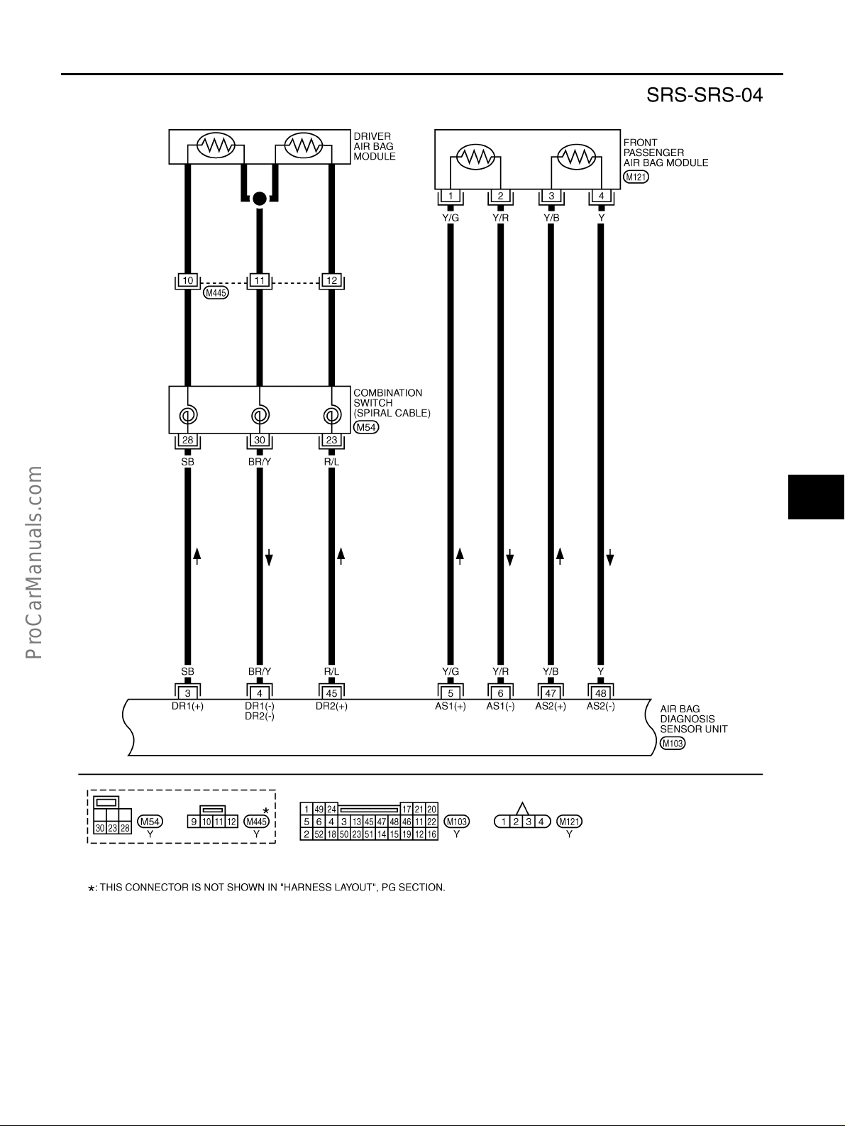
SUPPLEMENTAL RESTRAINT SYSTEM (SRS) PFP:28556 SRS Configuration EHS0009E
WHIA0042E
The air bag deploys if the diagnosis sensor unit activates while the ignition switch is in the ON or START position.
The collision m odes for which su pp le me ntal restraint syst em s are a ct iv ate d are different among the SR S sy s tems. For example, the driver air bag module and front passenger air bag module are activated in a frontal collision but not in a side collision.
SRS configurations which are activated for some collision modes are as follows;
SRS configuration Frontal collision Left side collision Right side collision
Driver air bag module × ——
Front passenger air bag module × ——
Front LH seat belt pre-tensioner × ——
Front RH seat belt pre-tensioner × ——
Front LH side air bag module — × —
Front RH side air bag module — — ×
LH side curtain air bag module — × —
RH side curtain air bag module — — ×
Revision; 2004 April 2003 Q45
SRS-6

SUPPLEMENTAL RESTRAINT SYSTEM (SRS)
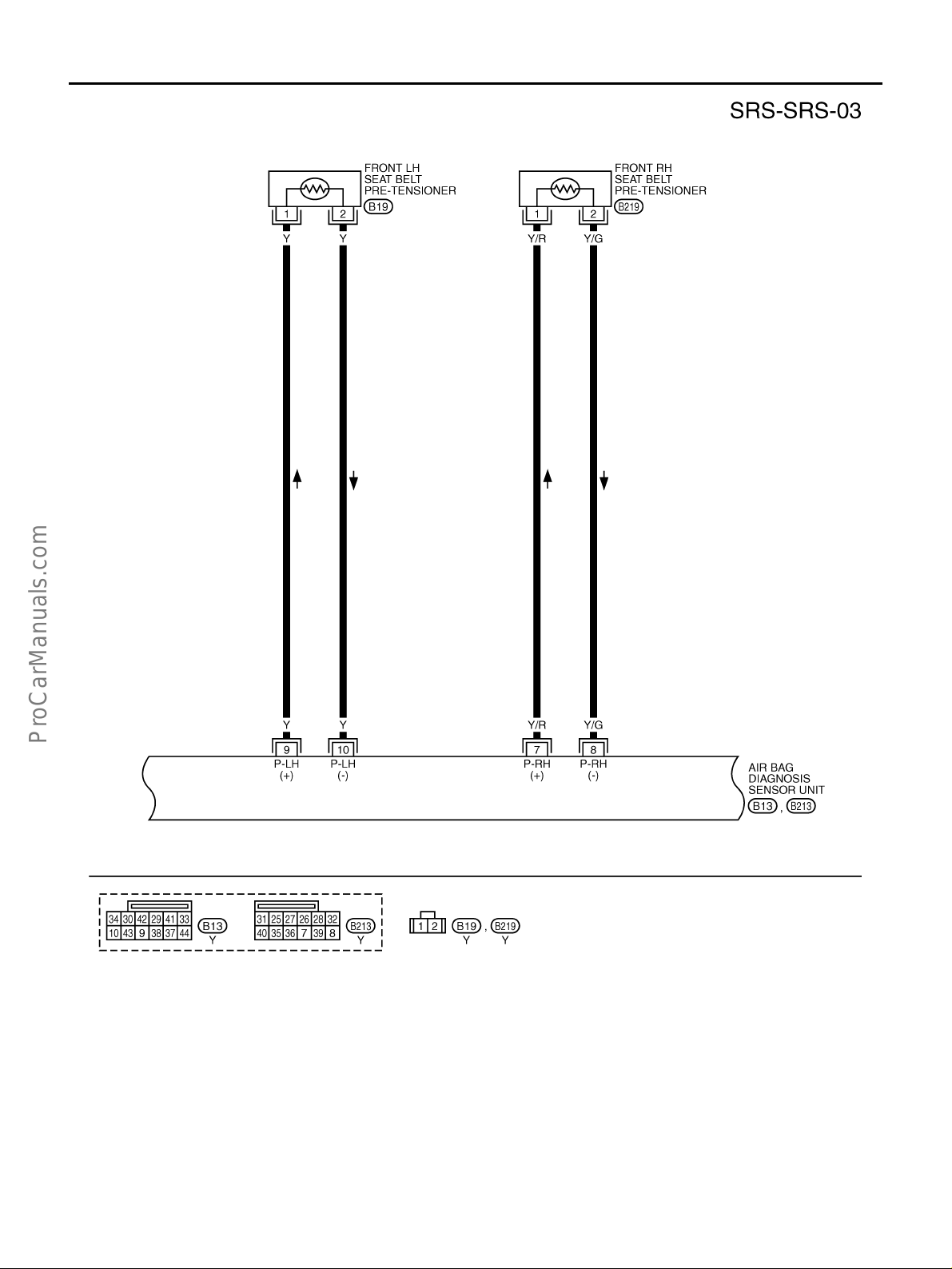
Front Seat Belt Pre-Tensioner With Load Limiter EHS0009F
The seat belt pre-tensioner system with load limiter is installed to
both the driver's seat and the front passenger's seat. It operates
simultaneously with the SRS air bag sy stem in the event of a fron tal
collision with an impact exceeding a specified level.
When the frontal collision with an impact exceeding a specified level
occurs, seat belt slack resulting from clothing or other factors is
immediately taken up by the pre-tensioner. Vehicle passengers are
securely restrained.
When passengers in a vehicle are t hrown forward in a collision a nd
the restraining fo rce of the seat belt exceeds a spec ified level, the
load limiter permits the specified extension of the seat belt by the
twisting of the ELR shaft, and a relaxation of the chest-area seat belt
SRS444
web tension while maintaining force.
Front Side Air Bag EHS0009G
Front side air bag is built-in type.
The front seat backs with built-in type side air bag have the la bels
shown in figure at right.
A
B
C
D
E
F
G
Side Curtain Air Bag EHS0009H
The side curtain air bag have the labels shown in figure at right.
SHIA0170E
BF-2006D
SRS
I
J
K
L
M
Revision; 2004 April 2003 Q45
SRS-7

TROUBLE DIAGNOSIS
TROUBLE DIAGNOSIS PFP:00004 Trouble Diagnoses Introduction EHS000LZ
CAUTION:
● Do not use electrical test equipment on any circuit related to the SRS unless instructed in this Ser-
vice Manual. SRS wir ing harnesses can be identified by yellow and/or orange harnesse s or harness connectors.
● Do not attempt to repair, splice or modify the SRS wiring harness. If the harness is damaged,
replace it with a new one.
● Keep ground portion clean.
DIAGNOSIS FUNCTION
The SRS self-d iagnosis results can be read by using “AIR BAG” warning lamp and/or CONSULT-II.
The User mode is exclusively prepared for the customer (driver). This mode warns the driver of a system malfunction through the operation of the “AIR BAG” warning lamp.
The Diagnosis mode allows the technician to locate and inspect the malfunctioning part.
The mode applications for the “AIR BAG” war ning lamp and CONSULT-II are as follows:
User mode Diagnosis mode Display type
“AIR BAG” warning lamp X X ON-OFF operation
CONSULT-II — X Monitoring
HOW TO PERFORM TROUBLE DIAGNOSES FOR QUICK AND ACCURATE REPAIR
A good understanding of the malfunction conditions can make troubleshooting faster and more accurate.
In general, each customer feels differently about a malfunction. It is important to fully understand the symptoms or conditions for a customer complaint.
Information from Customer
WHAT..... Vehicle model
WHEN..... Date, Frequencies
WHERE..... Road conditions
HOW..... Operating conditions, Symptoms
Preliminary Check
Check that the following parts are in good order.
● Battery (Refer to SC-4, "How to Handle Battery" .)
● Fuse (Refer to PG-2, "Schematic" .)
● System comp onent-to-har ness connections
Revision; 2004 April 2003 Q45
SRS-8

WORK FLOW
TROUBLE DIAGNOSIS
A
B
C
D
E
F
G
*1: SRS-8 *2: SRS-20 *3: SRS-22
*4: SRS-32 *5 SRS-26 *6 SRS-32
SRS
I
J
K
L
PHIA0217E
M
Revision; 2004 April 2003 Q45
SRS-9

TROUBLE DIAGNOSIS
SRS Components Parts Location EHS000M0
SHIA0178E
Revision; 2004 April 2003 Q45
SRS-10

TROUBLE DIAGNOSIS
Schematic EHS00094
A
B
C
D
E
F
G
SRS
I
J
K
L
M
THWM0001E
Revision; 2004 April 2003 Q45
SRS-11

TROUBLE DIAGNOSIS
Wiring Diagram-SRS- EHS0008E
THWM0023E
Revision; 2004 April 2003 Q45
SRS-12

TROUBLE DIAGNOSIS
A
B
C
D
E
F
G
SRS
I
J
K
L
M
THWM0019E
Revision; 2004 April 2003 Q45
SRS-13
TROUBLE DIAGNOSIS
THWM0020E
Revision; 2004 April 2003 Q45
SRS-14
TROUBLE DIAGNOSIS
A
B
C
D
E
F
G
SRS
I
J
K
L
M
THWM0005E
Revision; 2004 April 2003 Q45
SRS-15

TROUBLE DIAGNOSIS
THWM0021E
Revision; 2004 April 2003 Q45
SRS-16

TROUBLE DIAGNOSIS
A
B
C
D
E
F
G
SRS
I
J
K
L
M
THWM0022E
Revision; 2004 April 2003 Q45
SRS-17
TROUBLE DIAGNOSIS
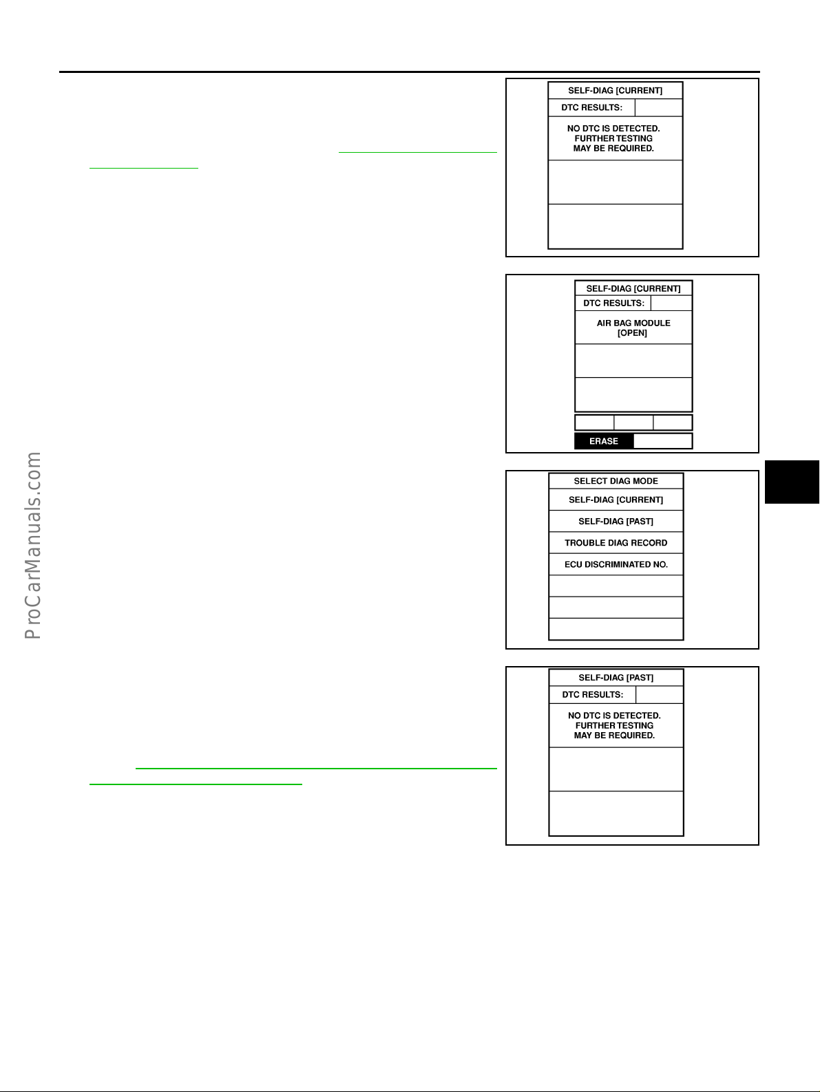
CONSULT-II Function EHS000MB
DIAGNOSIS MODE FOR CONSULT-II
● “SELF-DIAG [CURRENT]”
A current Self-dia gnosis result (also in dicated by the number o f warning lamp flashe s in the Diagnosis
mode) is displayed on the CONS ULT-II screen in real tim e. This refers to a malfu nctioning part re quiring
repairs.
● “SELF-DIAG [PAST]”
Diagnosis resul ts previously stored in the memory are dis played on the CONSULT-II screen. The stored
results are not erased until memory erasing is executed.
● “TROUBLE DIAG RECORD”
With TROUBLE DIAG RECORD, diagnosis results previously erased by a reset operation can be displayed on the CONSULT-II screen.
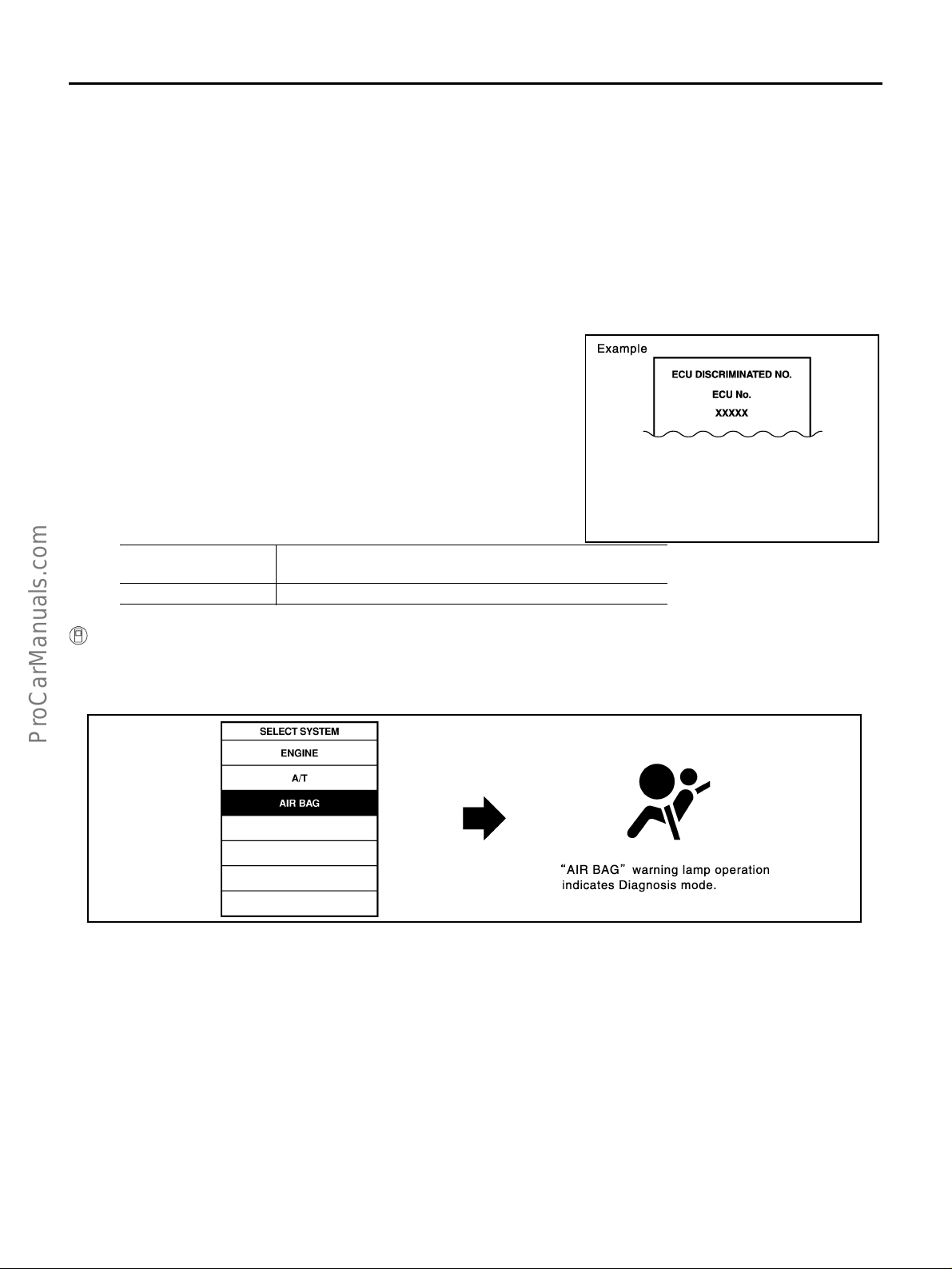
● “ECU DISCRIMINATED NO.”
The diagnosis sensor unit for each vehicle model is assigned
with its own, individual classification number. This number will
be displayed on the CONSULT-II screen, as shown. When
replacing the diagnosis sensor unit, refer to the part number for
the compatibility. After installation, replacement with a correct
unit can be checked by confirming this classification number on
the CONSULT-II screen.
After repair, make sure the discriminated number shown in the
below table and the discriminated number of diagnosis sensor
unit installed to vehicle are same.
Discriminated No.
F342 ×
Driver air bag module and passenger air bag module with side
air bag module and side curtain air bag module
PHIA0218E
HOW TO CHANGE SELF-DIAGNOSIS MODE WITH CONSULT-II
From User Mode to Diagnosis Mode
After selecting “AIR BAG” on the “SELECT SYSTEM” screen, Us er m ode au to ma tical ly chan ge s to Diag no s is
mode.
SRS803
Revision; 2004 April 2003 Q45
SRS-18

TROUBLE DIAGNOSIS
From Diagnosis Mode to User Mode
To return to User mode from Diagnosis mode, touch “BACK” key of CONSULT-II until “SELECT SYSTEM”
appears, Diagnosis mode automatically changes to User mode.
A
B
C
D
HOW TO ERASE SELF-DIAGNOSIS RESULTS
● “SELF-DIAG [CURRENT]”
A current Self -diagnosis result is displayed on the CONSULT-II screen in real time.
After the malfunction is repaired completely , no malfunction is detected on “SELF-DIAG [CURRENT]”.
● “SELF-DIAG [PAST]”
Return to the “SELF-DIAG [CURRENT]” CONSULT-II screen by touching “BACK” key of CONSULT-II and
select “SELF-DIAG [CURRENT]” in SELECT DIAG MODE. Touch “ERASE” in “SELF-DIAG [CURRENT]”
mode.
NOTE:
If the memory of the malfun ction in “SELF-DIAG [PAST]” is not erased, the Use r mode shows th e
system malfunction by the op eration of the warning la mp ev en if the malfunction is repaired co mpletely.
● “TROUBLE DIAG RECORD”
The memory of “TROUBLE DIAG RECORD” cannot be erased.
SRS804
E
F
G
SRS
I
J
K
L
SRS701
Revision; 2004 April 2003 Q45
SRS-19
M

TROUBLE DIAGNOSIS
Self-Diagnosis Function (Without CONSULT-II) EHS000MC
● The reading of these results is accomplished usin g one of two modes — “User mo de” and “Diagnosis
mode”.
● After a malfunction is repaired , turn the igni tion switc h OFF for at least one second , then back ON. Diag -
nosis mode returns to the User mode. At that time, the self-diagnostic result is cleared.
HOW TO CHANGE SELF-DIAGNOSIS MODE
PHIA0117E
HOW TO ERASE SELF-DIAGNOSIS RESULTS
After a malfunction is repaired, turn the ignition switch OFF for at least one second, then back ON. Diagnosis
mode returns to the User mode. At that time, the self-diagnostic result is cleared.
SRS Operation Check EHS000MD
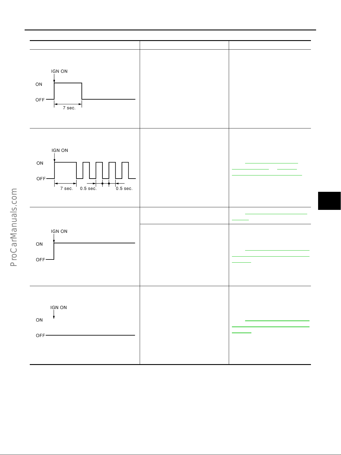
DIAGNOSTIC PROCEDURE 1
Checking Air Bag Operation by Using “AIR BAG” Warning Lamp-User Mode
1. Turn the ignition switch from OFF to ON, and check that the air bag warning lamp blinks.
2. Compar e th e SR S ai r bag w arn in g l am p bl ink in g pattern with t he
examples.
BF-1845D
Revision; 2004 April 2003 Q45
SRS-20
TROUBLE DIAGNOSIS
Warning lamp examples
“AIR BAG” warning lamp operation-User mode- SRS condition Reference item
A
B
SHIA0011E
SHIA0012E
SHIA0013E
● No malfunction is det ected.
● No further action is nece ssar y.
● The system is malfunc tioning and
need to be repaired as indicated.
● Air bag is deployed.
● Seat belt pre-tensioner is dep loyed.
● Diagnosis sensor uni t is ma lfunc tion-
ing.
● Air bag power supply circuit is mal-
functioning.
● SRS air bag warning lamp circuit is
malfunctioning.
—
Go to SRS-22, "
PROCEDURE 2" or SRS-32,
"DIAGNOSTIC PROCEDURE 6" .
Go to SRS-59, "
NOSIS" .
Go to SRS-37, "
“AIR BAG” Warning Lamp Does Not
Turn Off" .
DIAGNOSTIC
COLLISION DIAG-
Trouble Diagnoses:
C
D
E
F
G
SRS
I
J
K
● Diagnosis sensor uni t is ma lfunc tion-
ing.
● Air bag warning lamp circuit is ma l-
functioning.
SHIA0014E
Revision; 2004 April 2003 Q45
SRS-21
Go to SRS-38, "
“AIR BAG” Warning Lamp Does Not
Turn On" .
Trouble Diagnoses:
L
M

TROUBLE DIAGNOSIS
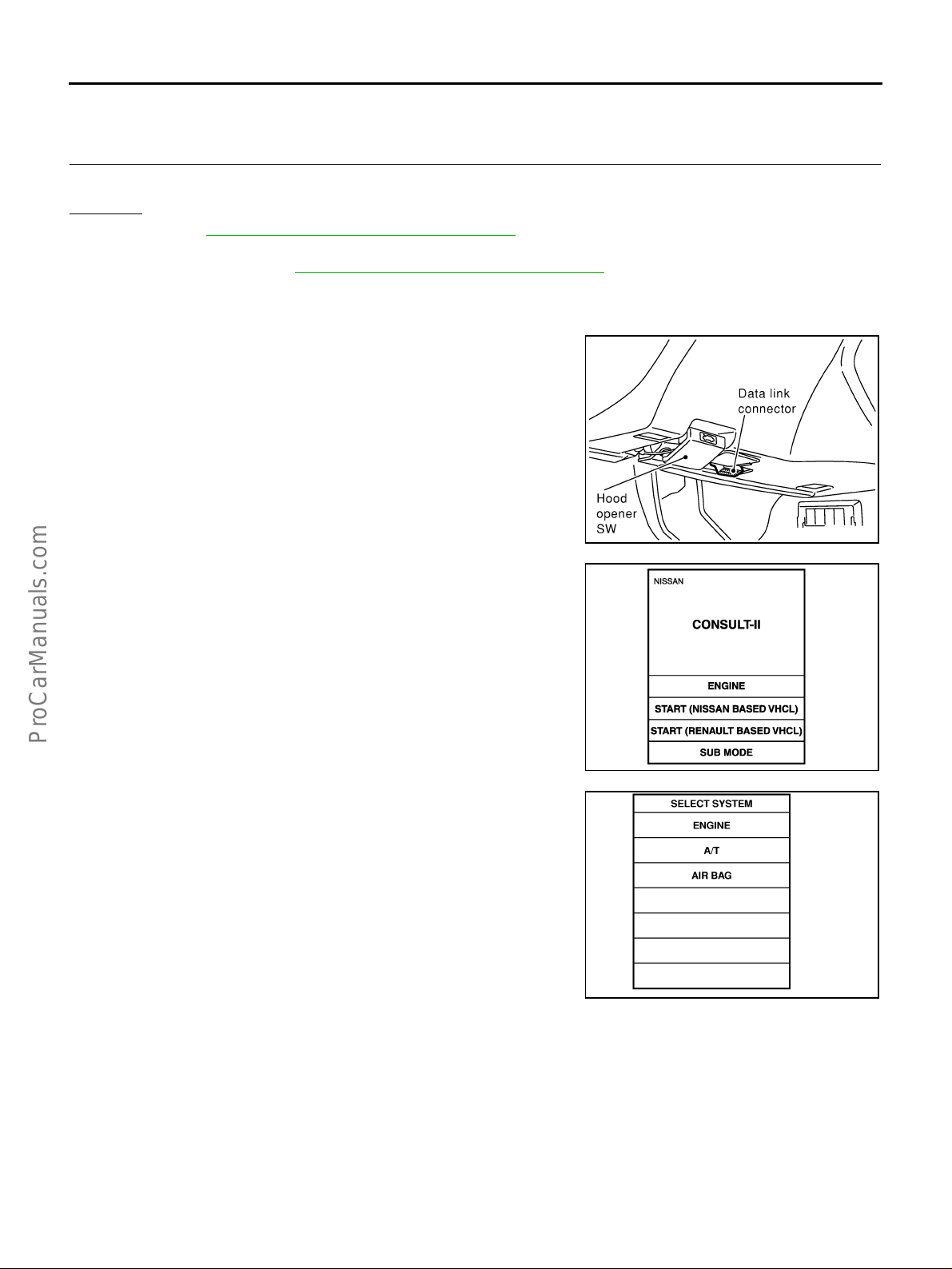
Trouble Diagnoses with CONSULT-II EHS000MH
DIAGNOSTIC PROCEDURE 2
1. T urn ignition switch OFF.
2. Connect CONSULT-II and CONSULT-II CONVERTER to the
data link connector.
SHIA0179E
3. Turn ignition sw itch ON.
4. Touch “START(NISSAN BASED VHCL)”.
5. Touch “AIR BAG”.
6. Touch “SELF-DIAG [CURRENT]”.
PHIA0157E
SRS771
SRS697
Revision; 2004 April 2003 Q45
SRS-22

TROUBLE DIAGNOSIS
7. Diagnostic code is displayed on “SELF-DIAG [CURRENT]”.
If no malfunction is detected on “SELF-DIAG [CURRENT]” even
though malfunction is detected in “SRS Operation Check”, check the
battery voltage. If the battery voltage is less than 9V, charge or
replace the battery. Then go to SRS-26, "
DURE 3" . If the battery voltage is OK, go to SRS-28, "DIAGNOSTIC
PROCEDURE 4 (CONTINUED FROM DIAGNOSTIC PROCEDURE
2)" to diagnose the following cases:
● Self-diagnostic result “SELF-DIAG [PAST]” (previously stored in
the memory) might not be erased after repair.
● The SRS system malfunctions intermittently.
DIAGNOSTIC PROCE-
A
B
C
SHIA0203E
D
E
F
G
SRS701
CONSULT-II Diagnostic Code Chart ("SELF-DIAG [CURRENT]")
Diagnostic item Explanation
NO DTC IS
DETECTED.
When malfunction is
indicated by the “AIR
BAG” warning lamp in
User mode.
● No malfunct ion is detect ed. —
DRIVER AIRBAG
MODULE
[OPEN]
DRIVER AIRBAG
MODULE
[VB-SHORT]
DRIVER AIRBAG
MODULE
[GND-SHORT]
DRIVER AIRBAG
MODULE
[SHORT]
ASSIST A/B MODULE
[OPEN]
ASSIST A/B MODULE
[VB-SHORT]
ASSIST A/B MODULE
[GND-SHORT]
ASSIST A/B MODULE
[SHORT]
● Driver air bag module ci rc uit is open (incl udi ng t he spiral cable). 1.Visua lly check the wiring harness
● Driver air bag module circuit is shorted to a power supply circuit
(including the spiral cable).
● Driver air bag modu le circuit is shor t ed to ground (including the
spiral cable).
● Driver air bag modu le circuit is shor t ed bet w een lin es.
● Front passenger air bag modul e ci rc ui t is open. 1.Visually check the wiring harness
● Front passenger air bag modul e ci rc uit is shor ted to a power -
supply.
● Front passenger air bag modul e ci rc uit is shor ted to ground.
● Front passenger air bag module circuit is shorted between lines.
● Low battery voltage (Less th an 9V) ● Go to SRS-22, "DIAGNOSTIC PRO-
● Self-diagnostic result “SELF-DIAG
[PAST]” (previously stored in the
memory) might not be erased after
repair.
● Intermittent ma lfunc tion has been
detected in the past.
Repair order
“Recheck SRS at each replacement”
CEDURE 2" after charging the bat-
tery.
● Go to SRS-28, "DIAGNOSTIC PRO-
CEDURE 4 (CONTINUED FROM
DIAGNOSTIC PROCEDURE 2)" .
● Go to SRS-28, "DIAGNOSTIC PRO-
CEDURE 5" .
connection.
2.Replace the harness if it has visible
damage.
3.Replace driver air bag module.
(Before disposal, it must be
deployed.)
4.Replace the spiral cable.
5.Replace the diagnosis sensor unit.
6.Replace the related harness.
connection.
2.Replace the harness if it has visible
damage.
3.Replace front passenger air bag
module. (Before disposal of it, it
must be deployed.)
4.Replace the diagnosis sensor unit.
5.Replace the related harness.
SRS
I
J
K
L
M
Revision; 2004 April 2003 Q45
SRS-23

TROUBLE DIAGNOSIS
Diagnostic item Explanation
CRASH ZONE SEN
● Crash zone sensor 1.Visually check the wiring harness
[UNIT FAIL]
CRASH ZONE SEN
[COMM FAIL]
SIDE MODULE LH
● Front LH side air bag module circui t is open . 1.Visually check the wiring harness
[OPEN]
SIDE MODULE LH
[VB-SHORT]
SIDE MODULE LH
● Front LH side air bag module circui t is short ed to a powe r sup -
ply circuit.
● Front LH side air bag module circui t is short ed to groun d.
[GND-SHORT]
SIDE MODULE LH
● Front LH side air bag module circui t is short ed bet w een lin es.
[SHORT]
SIDE MODULE RH
● Front RH side air bag module ci rc ui t is open. 1.Visually check the wiring harness
[OPEN]
SIDE MODULE RH
[VB-SHORT]
SIDE MODULE RH
● Front RH side air bag module ci rc uit is shor te d to a power sup-
ply circuit.
● Front RH side air bag module ci rc uit is shor te d to ground.
[GND-SHORT]
SIDE MODULE RH
● Front RH side air bag module ci rc ui t is shorte d bet we en line s.
[SHORT]
SATELLITE SENS LH
● LH side air bag (Satellite) sensor 1.Visually check the wiring harness
[UNIT FAIL]
SATELLITE SENS LH
[COMM FAIL]
SATELLITE SENS RH
● RH side air bag (Satellite) sensor 1.Visually check the wiring harness
[UNIT FAIL]
SATELLITE SENS RH
[COMM FAIL]
PRE-TEN FRONT LH
● Front LH pre-tensioner circuit is open. 1.Visually check the wiring harness
[OPEN]
PRE-TEN FRONT LH
[VB-SHORT]
PRE-TEN FRONT LH
● Front LH pre-tensioner circuit is shorted to a power supply cir-
cuit.
● Front LH pre-tensioner circuit is shorted to ground.
[GND-SHORT]
PRE-TEN FRONT LH
● Front LH pre-tensioner circuit is shorted between lines.
[SHORT]
Repair order
“Recheck SRS at each replacement”
connection.
2.Replace the harness if it has visible
damage.
3.Replace the crash zone sensor.
4.Replace the diagnosis sensor unit.
5.Replace the related harness.
connection.
2.Replace the harness if it has visible
damage.
3.Replace front LH setback assembly
(Front LH side air bag module).
(Before disposal, it must be
deployed.)
4.Replace the diagnosis sensor unit.
5.Replace the related harness.
connection.
2.Replace the harness if it has visible
damage.
3.Replace front RH setback assembly
(Front RH side air bag module).
(Before disposal, it must be
deployed.)
4.Replace the diagnosis sensor unit.
5.Replace the related harness.
connection.
2.Replace the harness if it has visible
damage.
3.Replace the LH side air bag (Satellite) sensor.
4.Replace the diagnosis sensor unit.
5.Replace the related harness.
connection.
2.Replace the harness if it has visible
damage.
3.Replace the RH side air bag (Satellite) sensor.
4.Replace the diagnosis sensor unit.
5.Replace the related harness.
connections.
2.Replace the harness if it has visible
damage.
3.Replace front LH seat belt.
(Before disposal, it must be activated.)
4.Replace the diagnosis sensor unit.
5.Replace the related harness.
Revision; 2004 April 2003 Q45
SRS-24

TROUBLE DIAGNOSIS
Diagnostic item Explanation
PRE-TEN FRONT RH
[OPEN]
PRE-TEN FRONT RH
[VB-SHORT]
PRE-TEN FRONT RH
[GND-SHORT]
PRE-TEN FRONT RH
[SHORT]
CURTAIN MODULE LH
[OPEN]
CURTAIN MODULE LH
[VB-SHORT]
CURTAIN MODULE LH
[GND-SHORT]
CURTAIN MODULE LH
[SHORT]
CURTAIN MODULE RH
[OPEN]
CURTAIN MODULE RH
[VB-SHORT]
CURTAIN MODULE RH
[GND-SHORT]
CURTAIN MODULE RH
[SHORT]
CONTROL UNIT
● Front RH pre-tensioner circuit is open. 1.Visually check the wiring harness
● Front RH pre-tensio ner circui t is short ed to a powe r sup ply cir-
cuit.
● Front RH pre-tensioner circuit is shorted to ground.
● Front RH pre-tensio ner circui t is shorted bet w een l ines.
● LH side curtain air bag modul e ci rcu it is open. 1.Visually check the wiring harn ess
● LH side curtain air bag module circuit is shorted to a power sup-
ply circuits.
● LH side curtain air bag module ci rcu it is shorted to ground.
● LH side curtain air bag module ci rcu it is shorted between lines.
● RH side curtain air bag mod ul e circuit is ope n. 1 . Visually che ck th e wir ing harn ess
● RH side curtain air bag module circuit is shorted to a power sup-
ply circuit.
● RH side curtain air bag modul e circui t is short ed to ground.
● RH side curtain air bag modul e circui t is short ed betw een lines.
● Diagnosis sensor unit is malfunctioning. 1.Visually check th e wir ing harness
Repair order
“Recheck SRS at each replacement”
connections.
2.Replace the harness if it has visible
damage.
3.Replace front RH seat belt.
(Before disposal, it must be activated.)
4.Replace the diagnosis sensor unit.
5.Replace the related harness.
connection.
2.Replace the harness if it has visible
damage.
3.Replace LH side curtain air bag
module.
(Before disposal, it must be
deployed.)
4.Replace the diagnosis sensor unit.
5.Replace the related harness.
connection.
2.Replace the harness if it has visible
damage.
3.Replace RH side curtain air bag
module.
(Before disposal, it must be
deployed.)
4.Replace the diagnosis sensor unit.
5.Replace the related harness.
connection.
2.Replace the diagnosis sensor unit.
A
B
C
D
E
F
G
SRS
I
J
K
NOTE:
● Follow the proced ures in nu merical ord er when repairin g malfun ctioni ng parts. Confirm whe ther malf unc-
tion is elimina ted us in g a ir b ag w a rni ng lam p or C ON SU LT-II each time repair is finished. If m al fun c tio n i s
still observed, proceed to the next step. When malfunction is eliminated, further repair work is not
required.
Revision; 2004 April 2003 Q45
SRS-25
L
M

TROUBLE DIAGNOSIS
DIAGNOSTIC PROCEDURE 3
Final checking after repairing SRS by using CONSULT-II — Diagnosis mode
1. After repairing SRS, connect both battery cables.
2. Connect CONSULT-II and CONSULT-II CONVERTER to data
link connector.
3. Turn ignition sw itch ON.
4. Touch “START(NISSAN BASED VHCL)”.
SHIA0179E
5. Touch “AIR BAG”.
6. Touch “SELF-DIAG [CURRENT]”.
PHIA0157E
SRS771
SRS697
Revision; 2004 April 2003 Q45
SRS-26
TROUBLE DIAGNOSIS
7. If no malfunction is detected on “SELF-DIAG [CURRENT]”,
repair of SRS is completed. Go to step 8.
If any malfunction is detected on “SELF-DIAG [CURRENT]”, the
malfunctioning part is not repaired completely or another malfunctioning part is detected. Go to SRS-22, "
PROCEDURE 2" , and repair malfunctioning part completely.
8. Touch “ERASE”.
NOTE:
Touch “ERASE” to clear the memory of the malfunction
(“SELF-DIAG [P AST]”).
If the memory of the malfunction in “SELF-DIAG [PAST]” is not
erased, the User mode shows the system malfunction by the
operation of the warning lamp even if the malfunction is repaired
completely.
DIAGNOSTIC
A
B
C
SRS701
D
E
F
G
SRS773
9. Touch “BACK” key of CONSULT-II to “SELECT DIAG MODE”
screen. Touch “SELF-DIAG [PAST]”.
10. Check that no malfunction is detected on “SELF-DIAG [PAST]”.
11. Touch “BACK” key of CONSULT-II until “SELECT SYSTEM”
appears in order to return to User mode from Diagnosis mode.
12. Turn ignition switch OFF then turn off and disconnect CONSULT-II.
13. Go to SRS-20, "
BAG” W arning Lamp-User Mode" .
Checking Air Bag Operation by Using “AIR
SRS697
SRS702
SRS
I
J
K
L
M
Revision; 2004 April 2003 Q45
SRS-27
TROUBLE DIAGNOSIS
DIAGNOSTIC PROCEDURE 4 (CONTINUED FROM DIAGNOSTIC PROCEDURE 2)
Inspecting SRS malfunctioning record
1. CONSIDER POSSIBILITY OF NOT ERASING SELF-DIAGNOSTIC RESULT AFTER REPAIRING
Is it the first time for maintenance of SRS?
Yes or No
Yes >> Go to SRS-22, "DIAGNOSTIC PROCEDURE 2" .
No >> Self-diagnostic result “SELF-DIAG [P AST]” (previously stored in the memory) might not be erased
after repair. Go to SRS-26, "
DIAGNOSTIC PROCEDURE 5
Inspecting SRS intermittent malfunction by using CONSULT-II — Diagnosis mode
1. T urn ignition switch OFF.
2. Connect CONSULT-II and CONSULT-II CONVERTER to data
link connector.
DIAGNOSTIC PROCEDURE 3" .
3. Turn ignition sw itch ON.
4. Touch “START(NISSAN BASED VHCL)”.
5. Touch “AIR BAG”.
SHIA0179E
PHIA0157E
SRS771
Revision; 2004 April 2003 Q45
SRS-28

TROUBLE DIAGNOSIS
6. Touch “SELF-DIAG [P AST]”.
7. If diagnostic codes are displayed on “SELF-DIAG [PAST]”, go to
step 10.
A
B
C
SRS697
D
E
F
G
SRS700
If no malfunction is detected on “SELF-DIAG [PAST]”, touch
“BACK” and go back to “SELECT DIAG MODE”.
8. Touch “TROUBLE DIAG RECORD”.
NOTE:
With “TROUBLE DIAG RECORD”, diagnosis results previously erased by a reset opera tion can be displayed.
9. Diagnostic code is displayed on “TROUBLE DIAG RECORD”.
10. Touch “PRINT”.
11. Compare diagnostic codes to SRS-30, "
Code Chart ("SELF-DIAG [PAST]" or TROUBLE DIAG
RECORD")" .
12. Touch “BACK” key of CONSULT-II until “SELECT SYSTEM”
appears.
13. Turn ignition switch OFF, then turn off and disconnect CONSULT-II, and both battery cables.
CONSULT-II Diagnostic
SRS702
SRS697
SHIA0182E
SRS
I
J
K
L
M
Revision; 2004 April 2003 Q45
SRS-29

TROUBLE DIAGNOSIS
14. Repair the sy stem as ou tlined by th e “Repair order ” in “Intermitte nt Malfunct ion Diagno stic Code Chart”,
that corresponds to the self-diagnostic result. For replacement procedure of component parts, refer to the
Removal and Installation procedure for the appropriate component.
15. Go to SRS-26, "
CONSULT-II Diagnostic Code Chart ("SELF-DIAG [PAST]" or TROUBLE DIAG RECORD")
Diagnostic item Explanation
NO DTC IS
DETECTED.
DRIVER AIRBAG
MODULE
[OPEN]
DRIVER AIRBAG
MODULE
[VB-SHORT]
DRIVER AIRBAG
MODULE
[GND-SHORT]
DRIVER AIRBAG
MODULE
[SHORT]
ASSIST A/B MODULE
[OPEN]
ASSIST A/B MODULE
[VB-SHORT]
ASSIST A/B MODULE
[GND-SHORT]
ASSIST A/B MODULE
[SHORT]
CRASH ZONE SEN
[UNIT FAIL]
CRASH ZONE SEN
[COMM FAIL]
SIDE MODULE LH
[OPEN]
SIDE MODULE LH
[VB-SHORT]
SIDE MODULE LH
[GND-SHORT]
SIDE MODULE LH
[SHORT]
DIAGNOSTIC PROCEDURE 3" , for final checking.
Repair order
“Recheck SRS at each replacement”
When malfunction is
indicated by the “AIR
BAG” warning lamp in
User mode.
● No malfunction is detected. ● Go to SRS-26, "DIAGNOSTIC PRO-
● Driver air bag module circuit is open (including the spiral cable). 1.Visually check the wiring harness
● Driver air bag module circuit is shorted to a power supply circuit
(including the spiral cable).
● Driver air bag module circ uit is shor ted to ground ( inc ludi ng th e
spiral cable).
● Driver air bag module circuit is shorted between lines.
● Front passenger air bag modul e circu it is ope n. 1.Visually check the wiring harness
● Front passenger air bag modul e circu it is sh orted t o a power
supply circuit.
● Front passenger air bag modul e circu it is sh orted t o grou nd.
● Front passenger air bag module circuit is shorted between lines.
● Crash zone sensor 1.Visually check the wiring harness
● Front LH side air bag module circui t is open . 1.Visually check the wiring harness
● Front LH side air bag module circui t is short ed to a powe r sup -
ply circuit.
● Front LH side air bag module circui t is short ed to groun d.
● Front LH side air bag module circui t is short ed bet w een lin es.
● Low battery voltage (Less than 9V) ● Go to SRS-26, "DIAGNOSTIC PRO-
CEDURE 3" .
CEDURE 3" .
connection.
2.Replace the harness if it has visible
damage.
3.If the harness check result is OK,
replace driver air bag module
(Before disposal, it must be
deployed.), diagnosis sensor unit
and spiral cable.
connection.
2.Replace the harness if it has visible
damage.
3.If the harness check result is OK,
replace the diagnosis sensor unit
and front passenger air bag module
(Before disposal, it must be
deployed.).
connection.
2.Replace the harness if it has visible
damage.
3.If the harness check result is OK,
replace crash zone sensor and diagnosis sensor unit.
connection.
2.Replace the harness if it has visible
damage.
3.If the harness check result is OK,
replace the diagnosis sensor unit
and front LH side air bag module.
(Before disposal, it must be
deployed.).
Revision; 2004 April 2003 Q45
SRS-30

TROUBLE DIAGNOSIS
Diagnostic item Explanation
SIDE MODULE RH
● Front RH side air bag mod u le circui t is open. 1.Visually check the wiring harness
[OPEN]
SIDE MODULE RH
[VB-SHORT]
SIDE MODULE RH
● Front RH side air bag mod ule circuit is sho rted to a power sup-
ply circuit.
● Front RH side air bag mod ule circuit is sho rted to groun d.
[GND-SHORT]
SIDE MODULE RH
● Front RH side air bag mod ule circuit is sho rted bet ween lines.
[SHORT]
SATELLITE SENS LH
● LH side air bag (Satel lit e) sen sor 1.Visually check the wiring harness
[UNIT FAIL]
SATELLITE SENS LH
[COMM FAIL]
SATELLITE SENS RH
● RH side air bag (Sate lli te) sensor 1.Visually check the wiring harness
[UNIT FAIL]
SATELLITE SENS RH
[COMM FAIL]
PRE-TEN FRONT LH
● Front LH pre-tensioner circuit is open. 1.Visually check the wiring harness
[OPEN]
PRE-TEN FRONT LH
[VB-SHORT]
PRE-TEN FRONT LH
[GND-SHORT]
PRE-TEN FRONT LH
[SHORT]
PRE-TEN FRONT RH
● Front LH pre-tensioner circuit is shorted to a power supply cir-
cuit.
● Front LH pre-tensioner circuit is shorted to ground.
● Front LH pre-tensioner circuit is shorted between lines.
● Front RH pre-tensioner circuit is open. 1.Visually check the wiring harness
[OPEN]
PRE-TEN FRONT RH
[VB-SHORT]
PRE-TEN FRONT RH
● Front RH pre-tensio ner circui t is short ed to a powe r sup ply cir-
cuit.
● Front RH pre-tensioner circuit is shorted to ground.
[GND-SHORT]
PRE-TEN FRONT RH
[SHORT]
CURTAIN MODULE LH
● Front RH pre-tensio ner circui t is short ed bet w een limes.
● LH side curtain air bag modul e ci rcu it is open. 1.Visually check the wiring harn ess
[OPEN]
CURTAIN MODULE LH
[VB-SHORT]
CURTAIN MODULE LH
● LH side curtain air bag module circuit is shorted to a power sup-
ply circuits.
● LH side curtain air bag module ci rcu it is shorted to ground.
[GND-SHORT]
CURTAIN MODULE LH
● LH side curtain air bag module ci rcu it is shorted between lines.
[SHORT]
Repair order
“Recheck SRS at each replacement”
connection.
2.Replace the harness if it has visible
damage.
3.If the harness check result is OK,
replace the diagnosis sensor unit
and front RH side air bag module
(Before disposal, it must be
deployed.)
connection.
2.Replace the harness if it has visible
damage.
3.If the harness check result is OK,
replace the diagnosis sensor unit
and LH side air bag (Satellite) sensor.
connection.
2.Replace the harness if it has visible
damage.
3.If the harness check result is OK,
replace the diagnosis sensor unit
and RH side air bag (Satellite) sensor.
connections.
2.Replace the harness if it has visible
damage.
3.If the harness check result is OK,
replace the diagnosis sensor unit
and front LH seat belt
(Before disposal, it must be activated.)
connections.
2.Replace the harness if it has visible
damage.
3.If the harness check result is OK,
replace the diagnosis sensor unit
and front RH seat belt
(Before disposal, it must be activated.)
connection.
2.Replace the harness if it has visible
damage.
3.If the harness check result is OK,
replace the diagnosis sensor unit
and LH side curtain air bag module.
(Before disposal, it must be
deployed.)
A
B
C
D
E
F
G
SRS
I
J
K
L
M
Revision; 2004 April 2003 Q45
SRS-31

TROUBLE DIAGNOSIS
Diagnostic item Explanation
CURTAIN MODULE RH
[OPEN]
CURTAIN MODULE RH
[VB-SHORT]
CURTAIN MODULE RH
[GND-SHORT]
CURTAIN MODULE RH
[SHORT]
CONTROL UNIT ● Diagnosis sensor unit is malfunctioning. 1.Visually check the wiring harness
● RH side curtain air bag module cir cui t is open. 1. Visually check the wiring harness
● RH side curtain air bag module circuit is shorted to a power sup-
ply circuit.
● RH side curtain air bag module cir cui t is shor ted to gr ound.
● RH side curtain air bag module cir cui t is shor ted bet w een l ine s.
“Recheck SRS at each replacement”
connection.
2.Replace the harness if it has visible
damage.
3.If the harness check result is OK,
replace the diagnosis sensor unit
and RH side curtain air bag module.
(Before disposal, it must be
deployed.)
connection.
2.Replace the diagnosis sensor unit.
Repair order
Trouble diagnoses without CONSULT-II. EHS000MI
DIAGNOSTIC PROCEDURE 6
Inspecting SRS malfunctioning parts by using "AIR BAG" warning lamp—Diagnosis mode
NOTE:
SRS will not en ter Diagnosis mode if no malfunction is detected in User mode.
1. Turn ignition sw itch ON.
2. After “AIR BAG” warning lamp lights for 7 seconds, turn ignition switch OFF within 1 second.
3. Wait more than 3 seconds.
4. Repeat the steps 1 to 3 two times.
5. Turn ignition sw itch ON.
SRS is now in Diagnosis mode.
“AIR BAG” warning lamp operates in Diagnosis mode as follows:
Revision; 2004 April 2003 Q45
SRS-32

TROUBLE DIAGNOSIS
WARNING LAMP FLASH CODE CHART
A
B
C
SHIA0026E
PHIA0185E
D
E
F
G
SRS
I
J
K
SHIA0028E
SHIA0029E
Revision; 2004 April 2003 Q45
SRS-33
L
M

TROUBLE DIAGNOSIS
SHIA0083E
SHIA0030E
SHIA0031E
SHIA0032E
Revision; 2004 April 2003 Q45
SRS-34

TROUBLE DIAGNOSIS
A
B
C
SHIA0033E
SHIA0034E
SHIA0035E
D
E
F
G
SRS
I
J
K
SHIA0084E
Revision; 2004 April 2003 Q45
SRS-35
L
M

TROUBLE DIAGNOSIS
SHIA0086E
Revision; 2004 April 2003 Q45
SRS-36

TROUBLE DIAGNOSIS
Trouble Diagnoses: “AIR BAG” Warning Lamp Does Not Turn Off EHS000MJ
DIAGNOSTIC PROCEDURE 7
1. SEE THE DEPLOYMENT OF AIR BAG MODULE
A
Is air bag module deployed?
Yes or No
Yes >> Refer to SRS-59, "COLLISION DIAGNOSIS" .
No >> GO TO 2.
2. CHECK THE AIR BAG FUSE
Check the fuse (No.20) [located in the fuse block (J/B)].
Refer to PG-2, "
OK or NG
OK >> GO TO 4.
NG >> GO TO 3.
POWER SUPPLY ROUTING" .
3. CHECK AIR BAG FUSE AGAIN
Replace “AIR BAG” fuse and turn ignition switch ON.
Does the
Yes >> Repair main harness.
No >> INSPECTION END.
“AIR BAG” fuse blow again?
4. CHECK DIAGNOSIS SENSOR UNIT
Connect CONSUL T-II and touch “START”.
● Is “AIR BAG” displayed on CONSULT -II?
Yes or No
Yes >> G O T O 5.
No >> Visually chec k the wi ring h arness co nnecti on of diagno -
sis sensor unit. If the harness connection check result is
OK, replace diagnosis sensor unit.
B
C
D
E
F
G
SRS
I
J
K
SRS771
5. CHECK HARNESS CONNECTION
Is harness connection between warning lamp and diagnosis sensor unit OK?
OK or NG
OK >> Replace diagnosis sens or un it.
NG >> Connect “AIR BAG” warning lamp and diagnosis sensor unit connector properly. If “AIR BAG”
warning lamp still does not go off, replace harness.
Revision; 2004 April 2003 Q45
SRS-37
L
M

TROUBLE DIAGNOSIS
Tr ouble Diagnoses: “AIR BAG” Warning Lamp Does Not Turn On EHS000MK
DIAGNOSTIC PROCEDURE 8
1. CHECK “METER” FUSE
Check the 10A meter fuse 9 [located in the fuse block (J/B)].
Refer to PG-2, "
OK or NG
OK >> GO TO 3.
NG >> GO TO 2.
POWER SUPPLY ROUTING" .
2. CHECK “METER” FUSE AGAIN
Replace 10A meter fuse (No.9) [located in the fuse block (J/B)] and turn ignition switch ON.
Does the meter fuse blow again?
Yes >> Repair the related harness.
No >> INSPECTION END.
3. CHECK HARNESS CONNECTION BETWEEN DIAGNOSIS SENSOR UNIT AND COMBINATION
METER
Disconnect diagnosis sensor unit connector and turn ignition switch ON.
● Does “AIR BAG” warning lamp turn on?
Yes or No
Yes >> Replace diagnosis sensor unit.
No >> Check the g round circuit of “AIR BAG” warning lamp.
Revision; 2004 April 2003 Q45
SRS-38
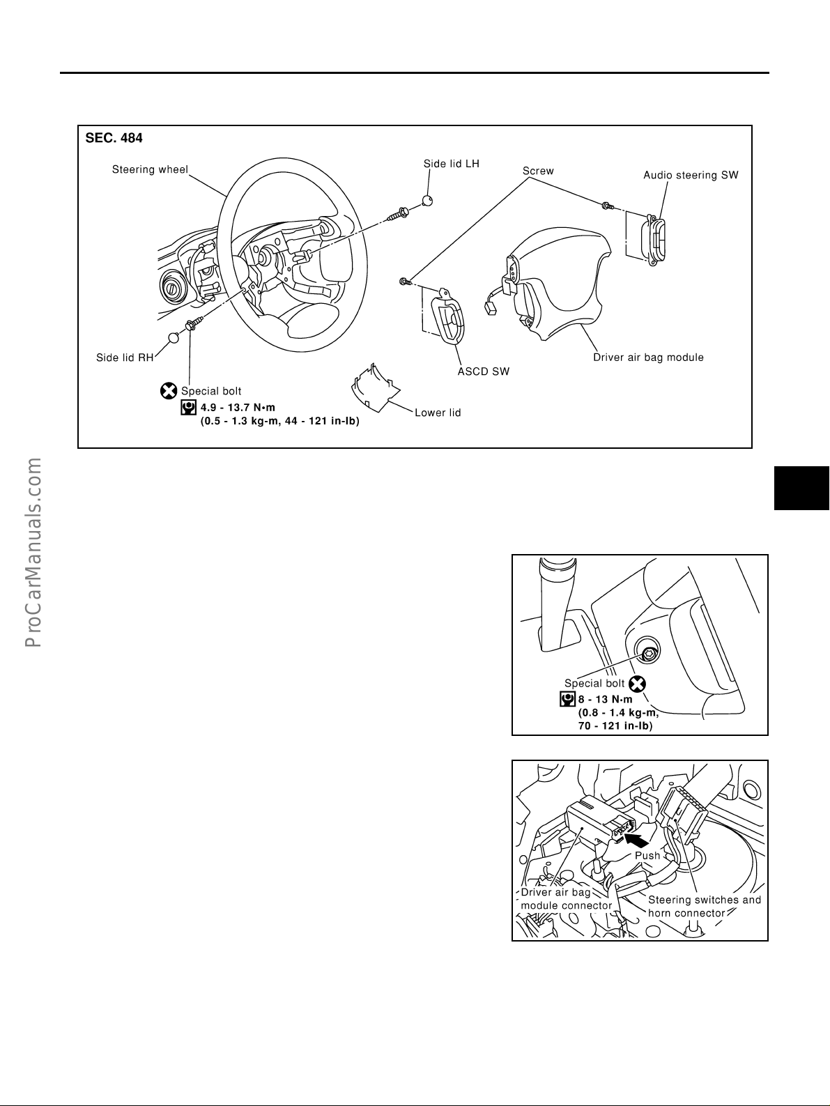
DRIVER AIR BAG MODULE
DRIVER AIR BAG MODULE PFP:K8510
Removal and Installation EHS0008N
A
B
C
D
E
F
SHIA0186E
REMOVAL
CAUTION:
● Before servicing SRS, turn the ignition switch off, disconnect both battery cables and wait at least
3 minutes.
● Always work from the side of driver air bag module.
1. Remove the side lids. Using Tamper resistant TORX socket
(T30), remove the special bolts at right and left.
2. Disconnect the air bag harness connector and steering switches
and horn connec tor, and then remove the air bag module.
G
SRS
I
J
K
L
SRS908
M
PHIA0239E
Revision; 2004 April 2003 Q45
SRS-39

DRIVER AIR BAG MODULE
3. Remove the ASCD and audio steering switch from the air bag
module.
CAUTION:
● Always work from the side of driver air bag module.
● Always place driver air bag module with pad side facing
upward.
● Do not insert any foreign objects (screwdriver, etc.) into
driver air bag module.
● Do not attempt to disassemble driver air bag module.
● Do not use old bolts after removal; replace with new bolts.
PHIA0240E
● Do not expose the driver air bag module to temperatures
exceeding 90°C (194°F).
● Replace driver air bag module if it has been dropped or sus-
tained an impact.
● Do not allow oil, grease or water to come in contact with the
front passenger air bag module.
INSTALLATION
To install, reverse the removal proc edure sequence.
● After installing the air bag module, check that the contact clear-
ance of the horn switch is in the specified range in the right.
SRS443
SBF814E
SHIA0185E
Revision; 2004 April 2003 Q45
SRS-40

DRIVER AIR BAG MODULE
● For installing th e air bag module, tighte n the special bolts with
the center of th e horn pad pressed to make the contacts (RH/
LH) ON.
● After the work is completed, perform self-diagnosis to check that
no malfunction is detected. Refer to SRS-20, "
Check" .
SRS Operation
A
B
C
SHIA0184E
D
E
F
G
SRS
I
J
K
L
M
Revision; 2004 April 2003 Q45
SRS-41

SPIRAL CABLE
SPIRAL CABLE PFP:25554 Removal and Installation EHS0008O
SHIA0192E
REMOVAL
CAUTION:
● Before servicing SRS, turn the ignition switch off, disconnect both battery cables and wait at least
3 minutes.
1. Remove driver air bag module. Refer to SRS-39, "
2. Set the steering wheel in the neutral position.
3. Disconnect the horn connector.
4. Remove the column cover. Refer to IP-10, "
INSTRUMENT PANEL ASSEMBLY" .
5. Disconnect the horn swit ch connector, then the spiral cable co nnector.
CAUTION:
Do not tap or bump the steering wheel.
6. Remove steering wheel with steering wheel puller. Be careful
not to over-tighten puller on steering wheel.
Removal and Installation" .
SRS676
7. Remove the spiral cable fixing screws, and while pushing the
upper plastic tab, remove the spiral cable.
CAUTION:
● Do not attempt to disassemble spiral cable.
● Do not apply lubricant to the spiral cable.
8. Remove the wiper washer switch and lighting switch from the
spiral cable.
SHIA0193E
Revision; 2004 April 2003 Q45
SRS-42

SPIRAL CABLE
CAUTION:
● Also, with the steering linkage disconnectedly cable may snap by turning the steering wheel
beyond the limited number o f turns. The spiral cable can be turned to the left about 2.5 turns from
the right end position.
A
INSTALLATION
To install, reverse the removal procedure sequence.
CAUTION:
● The spiral cable may snap due to steering operation if the
cable is installed in an improper position.
● Also, with the steering linkage disconnectedly cable may
snap by turning the steering wheel beyond the limited number of turns. The spiral cable can be turned to the left about
2.5 turns from the right end position.
● After the work is completed, perform self-diagnosis to check that
no malfunction is detected. Refer to SRS-20, "
Check" .
SRS Operation
B
C
D
E
SHIA0091E
F
G
SRS
I
J
K
L
M
Revision; 2004 April 2003 Q45
SRS-43
FRONT PASSENGER AIR BAG MODULE
FRONT PASSENGER AIR BAG MODULE PFP:K8515 Removal and Installation EHS0008Q
REMOVAL
CAUTION:
● Before servicing SRS, turn the ignition switch off, disconnect both battery cables and wait at least
3 minutes.
● Always work from the side of or under front passenger air bag module.
1. Remove the instrument lower cover, and discon nect the passenger air bag harness connector.
2. Remove the glove box. Refer to IP-10, "
3. Remove the special bolt s.
INSTRUMENT PANEL ASSEMBLY" .
SHIA0187E
4. Pull the p assen ger ai r b ag modu le t owar d the r ear o f th e veh icle,
while being careful not to impact it. Pull it from between the
instrument panel and th e steering wheel memb er downward to
remove.
CAUTION:
● Always place front passenger air bag modu le with caution
label side facing upward.
● Do not insert any foreign objects (screwdriver, etc.) into
front passenger air bag module.
● Do not attempt to disassemble front passenger air bagmod-
ule.
● Do not use old bolts after removal; replace with new bolts.
● Replace front passenger air bag module if it has been
dropped or sustained an impact.
● Do not expose the front passenger air bag module to tem-
peratures exceeding 90 °C (194°F).
● Do not allow oil, grease or water to come in contact with the front passenger air bag module.
● After front passenger air bag module inflates, the instrument panel assembly should be replaced.
SHIA0188E
SBF814E
INSTALLATION
To install, reverse the removal procedure.
CAUTION:
● Always work from the side of or under front passenger air bag module.
● After the work is completed, perform self-diagnosis to check that no malfunction is detected.
Refer to SRS-20, "
Revision; 2004 April 2003 Q45
SRS Operation Check" .
SRS-44

FRONT SIDE AIR BAG MODULE
FRONT SIDE AIR BAG MODULE PFP:K8EH0
Removal and Installation EHS0008R
SHIA0189E
A
B
C
D
REMOVAL
WARNING:
● Removal of front side air bag module should only be done to allow deployment of front sid e air
bag module prior to disposal of seatback assembly.
Only complete se atbac k asse mblie s can be replace d. Ref er to SE-195, "
ASSEMBLY" .
CAUTION:
● Before servicing SRS, turn the ignition switch off, disconnect both battery cables and wait at least
3 minutes.
● Always work from the rear of the front side air bag module.
1. Remove the front seat. Refer to SE-188, "
2. Remove the seat back board.Refer to SE-194, "
3. Remove the seat back trim and pad. Refer to SE-194, "
Removal and I nstallation" .
SEATBACK TRIM AND PAD" .
SEATBACK TRIM AND PAD" .
4. Remove the sea t ba ck r ear f ini sh er, and remove the retaine rs se cu rin g t h e s eat c us hi on tr i m. R e fer to SE-
195, "SEAT CUSHION TRIM AND PAD" .
5. Uncap the air bag module harness fixing, and remove the harness connector on the side air bag from the
seat cushion.
6. Remove the side air bag module fixing nuts, and remove the fr ont side air bag module.
CAUTION:
● When using a clip removal tool to remove the seat back
board, t ake care n ot t o da mage the h arnes s fo r fro nt si de ai r
bag module .
● Always place the front side air bag module standing with
the stud bolt side setting bottom.
● Do not insert a ny foreign objects (screwdrivers) into front
side air bag m odule
● Do not attempt to disassemble front side air bag module.
REMOVAL OF SEATBACK
E
F
G
SRS
I
J
K
L
M
SRS623
● Do not use old bolts after removal; replace with new bolts.
Revision; 2004 April 2003 Q45
SRS-45

FRONT SIDE AIR BAG MODULE
● Replace front side air bag m odule if it has been d ropped or
sustained an impact.
● Do not expose the front side air bag module to tempera-
tures exceed ing 90°C (194°F).
● Do not allow oil, grease or water to come in contact with the
front side air bag module.
● After front side air bag module inflates, front seatback
assembly must be replaced.
SBF814E
INSTALLATION
Install in the reverse order of removal.
CAUTION:
● Always work from the side of or under front side air bag module.
● After the work is completed, perform sel f-diagnosis to make sure tha t no malfu nction is detect ed.
Refer to SRS-20, "
SRS Operation Check" .
Revision; 2004 April 2003 Q45
SRS-46

SIDE CURTAIN AIR BAG MODULE
SIDE CURTAIN AIR BAG MODULE PFP:985P0
Removal and Installation EHS0008S
A
B
C
D
E
F
SHIA0190E
REMOVAL
CAUTION:
● Before servicing SRS, turn the ignition switch off, disconnect both battery cables and wait at least
3 minutes.
● Always work from the side of the side curtain air bag module.
1. Remove rear pillar finisher. Refer to EI-37, "
2. Disconnect the side curtain air bag module connector.
3. Remove headlining. Refer to EI-49, "
Removal and I nstallation" .
4. Remove side curtain air bag module fixing bolts, and remo ve the side cu rtai n air ba g mo du le.
CAUTION:
● Always place the side curtain air bag module with the caution label facing upward.
● Do not attempt to disassemble side curtain air bag module.
● Do not insert any foreign objects (screwdriver, etc.) into air
bag module connector.
● Replace side curtain air bag m odule if it has been drop ped
or sustained an impact.
● Do not expose the air bag modu le to temp eratures exce ed-
ing 90°C (194°F).
● Do not allow oil, grease or water to come in contact with the
side curtain air bag module.
Removal and Installation" .
G
SRS
I
J
K
L
M
SBF814E
INSTALLATION
To install, reverse the removal procedure sequence.
CAUTION:
● Always work from the side of the side curtain air bag module.
● After replacement of side curtain air bag module, perform self-diagnosis to check that no malfunc-
tion is detected. Refer to SRS-20, "
Revision; 2004 April 2003 Q45
SRS Operation Check" .
SRS-47

CRASH ZONE SENSOR
CRASH ZONE SENSOR PFP:98531 Removal and Installation EHS0009M
REMOVAL
CAUTION:
● Before servicing SRS, turn the ignition switch off, disconnect both battery cables and wait at least
3 minutes.
1. Remove front grille. Refer to EI-19, "
2. Remove crash zone sensor connector.
3. Remove crash zone sensor fixing nuts.
CAUTION:
● Replace crash zone sensor if it has been dropped or sustained an impact.
● Do not attempt to disassemble crash zone sensor.
Removal and Installation" .
SHIA0191E
INSTALLATION
To install, reverse the removal proc edure sequence.
CAUTION:
● Check crash zone sensor for proper installation.
● After the work is complete, perform se lf-d iag nos is to c hec k t hat no malfunction is dete cte d. Refe r
to SRS-20, "
SRS Operation Check" .
Revision; 2004 April 2003 Q45
SRS-48

SIDE AIR BAG (SATELLITE) SENSOR
SIDE AIR BAG (SATELLITE) SENSOR PFP:98830
Removal and Installation EHS0008U
REMOVAL
CAUTION:
● Before servicing SRS, turn the ignition switch off, disconnect both battery cables and wait at least
3 minutes.
1. Remove seat belt pre-tensioned. Refer to EI-37, "
TRIM" and SB-3, "Removal and Installation of Front Seat Belt" .
2. Remove side air bag (Satellite) sensor fixing nuts.
3. Remove the side air bag (Satellite) sensor connector.
BODY SIDE
A
B
C
D
E
CAUTION:
● Do not use old bolts, replace with new ones.
● Check side air bag (Satellite) sensor to ensure they are free of deformities, dents, cracks or rust. If
it shows any visible signs of damage, replace it with new one.
● Do not attempt to disassemble side air bag (Satellite) sensor.
● Replace side air bag (Satellite) sensor if it has been dropped or sustained an impact.
● When the front side air bag or side curtain air bag deploys, always replace it with a new one.
INSTALLATION
To install, reverse the removal procedure sequence.
CAUTION:
● Check side air bag (Satel lite) sensor for proper installation.
● After replacement of side air bag (S atellite) sensor, perform self-diag nosis to check that no mal-
function is detected. Refer to SRS-20, "
SRS Operation Check" .
SHIA0194E
F
G
SRS
I
J
K
L
M
Revision; 2004 April 2003 Q45
SRS-49

FRONT SEAT BELT PRE-TENSIONER
FRONT SEAT BELT PRE-TENSIONER PFP:86884 Removal and Installation EHS000O5
To removal and installation procedures, refer to SB-3, "Removal and Installation of Front Seat Belt " .
Revision; 2004 April 2003 Q45
SRS-50

DIAGNOSIS SENSOR UNIT
DIAGNOSIS SENSOR UNIT PFP:28556
Removal and Installation EHS0008W
REMOVAL
CAUTION:
● Before servicing SRS, turn the ignition switch off, disconnect both battery cables and wait at least
3 minutes.
1. Disconnect each harness connector for the air bag module and
seat belt pre-tensioner.
2. Remove center console. Refer to IP-10, "
ASSEMBLY" .
3. Disconnect diagnosis sensor unit connector.
4. Remove the installation bolts.
CAUTION:
● Do not use old bolts. Replace with new ones.
● Check diagnosis se nsor uni t brackets to ensure it is free o f
deformities, dents, cracks or rust. If it shows any visible
signs of damage, replace it with new one.
● Replace diagnosis sensor unit if it has been dropped or sustained an impact.
INSTRUMENT PANEL
PHIA0272E
A
B
C
D
E
F
INSTALLATION
To install, reverse the removal procedure sequence.
Concerning the diag no si s sensor unit tightening torqu e as follo w s ;
Bolts type Tightening torque
TORX bolts (For TAMPER RESISTANT T50 size) 14.7 - 24.5 N.m (1.5 - 2.5 kg-m, 11 - 18 ft-lb)
Hexagon bolts 19.6 - 29.4 N.m (2.0 - 2.9 kg-m, 15 - 21 ft-lb)
CAUTION:
● Check the diagnosis sensor unit for proper installation.
● After replacement of diagnosis sensor unit, perform self-diagnosis to check that no malfunction is
detected. Refer to SRS-20, "
SRS Operation Check" .
ECU DISCRIMINATED NO.
After replacing the diagnosi s sensor unit, confirm that the di agnosis sensor un it identification No. is F342.
G
SRS
I
J
K
L
M
Revision; 2004 April 2003 Q45
SRS-51
DISPOSAL OF AIR BAG MODULE AND SEAT BELT PRE-TENSIONER
DISPOSAL OF AIR BAG MODULE AND SEAT BELT PRE-TENSIONER PFP:00014 Caution for Air Bag Module and Seat Belt Pre-Tensioner EHS0009A
● Before disposing of air bag module and se at be lt pre-te nsione r, or vehicles equip ped with such s ystems,
deploy the systems . If such syste ms ha ve alre ad y been deploy ed du e to an acc iden t, disp ose of them as
indicated in SRS-58, "
● When deploying the air bag module and seat be lt pre-tensioner, always use the Special Service Tool;
Deployment tool [SST: KV99106400 (J38381)].
● When deploying the air bag module and seat belt pre-tensioner, stand at least 5 m (16 ft) away from the
deployment component.
● When deploying air bag module and seat belt pre-tensioner, a fairly loud noise is made, followed by
smoke being release d. The smok e is not pois onous, however, be careful not to inhal e smoke si nce it irritates the throat and can cause choking.
● Always activate one air bag module at a time.
● Due to heat , le av e ai r ba g m odul e u na t te nded f or m or e th an 30 mi nu t es aft er d eplo ym en t. Al so le av e s ea t
belt pre-tensioner unattended for more than 10 minutes after deployment.
● Be sure to wear gloves when handling a deployed air bag module and seat belt pre-tensioner.
● Never apply water to the deployed air bag module and seat belt pre-tensioner.
● Wash your hands clean after finishing work.
● Place the vehicle outdoors with an open space of at least 6 m (20 ft) on all sides when deploying air bag
module and seat belt pre-tensioner while mounted in vehicle.
● Use a voltmeter to make sure the vehicle battery is fully charged.
● Do not dispose of the air bag module and seat belt pre-tensioner un-deployed.
DISPOSING OF AIR BAG MODULE AND SEAT BELT PRE-TENSIONER" .
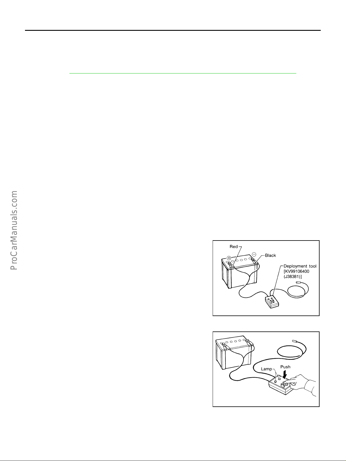
CHECKING DEPLOYMENT TOOL
Connecting to Battery
CAUTION:
The battery must show voltage of 9.6V or more.
Remove the battery from the vehicle and place it on dry wood blocks
approximately 5 m (16 ft) away from the vehicle.
● Wait 3 minutes after the vehicle battery is disconnected before
proceeding.
● Connect red clip of deployment tool to battery positive terminal
and black clip to negative terminal.
Make sure the polarity is correct. The right side lamp in the tool,
marked “deployment tool power”, should glow with a green
light. If the right side lamp glo ws red, reverse the connections
to the battery.
Deployment Tool Check
Press the de ployment tool switch to the ON position. T he left side
lamp in the t ool, marked “air bag connector vo ltage” should i lluminate. If it does not illuminate, replace the tool.
SRS019
SBF266H
Revision; 2004 April 2003 Q45
SRS-52

DISPOSAL OF AIR BAG MODULE AND SEAT BELT PRE-TENSIONER
Air Bag Deployment Tool Lamp Illumination Chart (Battery Connected)
Left side lamp, green*
Switch operation
OFF OFF ON
ON ON ON
*: If this lamp glows red, the tool is connected to the battery inc orrect l y. Reverse the connections and make sure the lamp gl o ws gr een.
“AIR BAG CONNECTOR
VOLTAGE”
DEPLOYMENT PROCEDURES FOR AIR BAG MODULE (OUTSIDE OF VEHICLE)
Right side lamp, green*
“DEPLOYMENT TOOL
POWER”
A
B
C
Unless the vehicle is being scrapped, deploying the air bag in the
vehicle is not recommended. This may cause damage to the vehicle
interior.
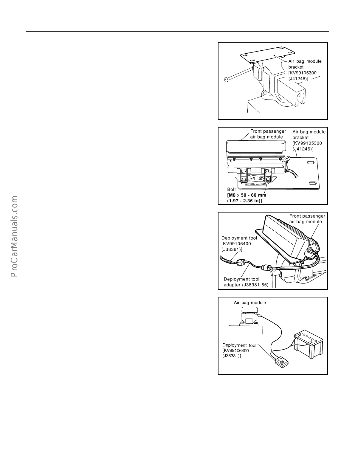
Anchor air bag module bracket [SST: KV99105300 (J41246)] in a
vise secured to a firm foundation during deployment.
Deployment of Driver Air Bag Module (Outside of Vehicle)
1. Using wire, secure air bag module to air bag module bracket
[SST: KV99105300 (J41246)] at two plac es .
CAUTION:
Use wire of at least 1 mm (0.04 in) diameter.
2. Firmly secure air bag module bracket [SST: KV99105300
(J41246)] with air bag module attached, in a vise.
SRS232-C
SRS233
D
E
F
G
SRS
I
J
K
3. Connect deployment tool adapter (SST: J38381-70) to deployment tool [SST: KV99106400 (J38381 )] to air bag module connector.
SRS906
4. Connect red c lip of deployment t ool to battery positi ve terminal
and black clip t o negative terminal.
5. The lamp on the righ t side of the tool, ma rked “deploy ment tool
power”, should glow green, not red.
6. Press the butto n on the deployment too l. The left side lamp on
the tool, marked “air bag connector voltage”, will illuminate and
the air bag modu le will deploy.
CAUTION:
When deploying the driv er air bag module, stand at least 5 m
(16 ft) away from the air bag module.
SRS235
Revision; 2004 April 2003 Q45
SRS-53
L
M
DISPOSAL OF AIR BAG MODULE AND SEAT BELT PRE-TENSIONER
Deployment of Front Passenger Air Bag Module (Outside of Vehicle)
1. Make an 8.5 mm (0.335 in) diameter hole in air bag module
bracket [SST: KV99105300 (J412 46)] at the position shown in
figure at right.
2. Firmly secure air bag module bracket [SST: KV99105300
(J41246)] in a vise.
3. Match the two holes in air ba g mo du le brac ket (held in vise) and
front passenger air bag module and fix them with two bolts [M8 ×
25 - 30 mm (0.98 - 1.18 in)].
CAUTION:
If a gap exists between front passenger air bag mo dule a nd
air bag module bracket, use a pie ce of wood ins erted in the
gap to stabilize the air bag module.
SRS232-C
4. Connect deployment tool adapter (SST: J38381-65) to deployment tool [SST : KV99106400 (J38381)] connector and front passenger air bag module connector.
5. Connect red clip of deployment tool to battery positive terminal
and black clip to negative terminal.
6. The lamp on the right side of the to ol, marked “deploym ent tool
power”, should glow green, not red.
7. Press the button on the deployment tool. The left side lamp on
the tool, marked “ai r bag connector voltage ”, will illuminate and
the air bag module will deploy.
CAUTION:
● When deploying the front passenger air bag module, do not
stand on the deploying side.
● Stand at least 5 m (16 ft) away from the air bag module.
SHIA0195E
SHIA0196E
SRS020-B
Revision; 2004 April 2003 Q45
SRS-54

DISPOSAL OF AIR BAG MODULE AND SEAT BELT PRE-TENSIONER
Deployment of Front Side Air Bag Module (Outside of Vehicle)
1. Make 6.5 mm (0.256 in) diameter holes in air bag module
bracket [SST: KV99105300 (J41246)] at the position shown in
figure at left.
A
B
C
2. Firmly secure air bag module bracket [SST: KV99105300
(J41246)] in a vise.
3. Insert the stu d bolts of side air bag mo dule into the two ho les in
air bag module bracket (held in vise) and fix them with two M6
nuts.
CAUTION:
Side air bag module should be sec ured to air bag module
bracket [SST: KV99105300 (J41246)] in a vise with stud bolt
side setting bottom.
4. Connect de ployment tool adapte r [SST: KV9 9108300 (J38381-
35)] to deploym ent tool [SST: KV99106400 (J38381)] connecto r
and connector on air bag module.
SRS490-B
SHIA0197E
SHIA0176E
D
E
F
G
SRS
I
J
K
5. Connect red c lip of deployment t ool to battery positi ve terminal
and black clip t o negative terminal.
6. The lamp on the righ t side of the tool, ma rked “deploy ment tool
power”, should glow green, not red.
7. Press the butto n on the deployment too l. The left side lamp on
the tool, marked “air bag connector voltage”, will illuminate and
the air bag modu le will deploy.
CAUTION:
When deploying the front side air bag module, stand at
least 5 m (16 ft) away from the air bag module.
PHIA0108E
Revision; 2004 April 2003 Q45
SRS-55
L
M

DISPOSAL OF AIR BAG MODULE AND SEAT BELT PRE-TENSIONER
Deployment of Side Curtain Air Bag Module (Outside of Vehicle)
1. Cut the inflator from si de curtain ai r bag module.
2. Connect deployment tool adapter [SST: KV99109000 (J44230)]
to the inflator.
SHIA0198E
3. Put the inflator connected with the deployment tool adaptor
[SST: KV99109000 (J44230)] into a tire without wheel.
4. Put the tire with the i nflato r onto anot her tire wi thout wheel . Add
an additional tire without wheel and then a tire mounted on a
wheel on top.
CAUTION:
Tie all tires together with a strap i n orde r keep them standing.
5. Connect red clip of deployment tool to battery positive terminal
and black clip to negative terminal.
6. The lamp on the right side of the to ol, marked “deploym ent tool
power”, should glow green, not red.
7. Press the button on the deployment tool. The left side lamp on
the tool, marked “air bag connector voltage”, will illuminate and the air bag module will deploy.
CAUTION:
When deploying the side c urtain air bag modu le, stand at least 5 m (16 ft) away from the s ide cu rtain air bag module.
SHIA0200E
SHIA0201E
WHIA0048E
Revision; 2004 April 2003 Q45
SRS-56

DISPOSAL OF AIR BAG MODULE AND SEAT BELT PRE-TENSIONER
DEPLOYMENT PROCEDURES FOR SEAT BELT PRE-TENSIONER (OUTSIDE OF VEHICLE)
1. Firmly grip pre-tensioner in a vise and cut the webbing off.
A
B
C
2. Connect deployment tool [SST: KV99106400 (J38381)] and
deployment tool adapter [SST : KV99108200 (J38381-80)] yellow
connector to front seat be lt pre - ten s ion er co nn ec to r.
3. Connect red c lip of deployment t ool to battery positi ve terminal
and black clip t o negative terminal.
4. The lamp on the righ t side of the tool, ma rked “deploy ment tool
power”, should glow green, not red.
5. Press the butto n on the deployment too l. The left side lamp on
the tool, marked “seat be lt pr e-tensio ner co nnec tor vo ltage”, w ill
illuminate and the seat belt pr e-tensioner will deploy.
CAUTION:
When deploying the front seat belt pre-tensioner, stand at
least 5 m (16 ft) away from the seat belt pre-tensioner.
WHIA0034E
PHIA0221E
SRS242
D
E
F
G
SRS
I
J
K
DEPLOYMENT OF AIR BAG MODULE AND SEAT BELT PRE-TENSIONER WHILE MOUNTED IN VEHICLE
When disposing of a vehicle, deploy air bag module and seat belt pre-tensioners while they are mounted in
vehicle.
CAUTION:
When deploying air bag module or seat belt pre-tensioner, ensure vehicle is empty.
1. Disconnect both battery cabl es and wait 3 minutes.
2. Disconnect air bag module and seat belt pre-tensioner connector.
3. Connect deplo y me nt too l [SST: KV99106400 (J38381)] to air bag module .
For driver air bag module, attach deployment tool adapter (SST: J38381-70) to the tool connector.
For front passenger air bag mod ule , attach de plo y me nt to ol ada pte r (SST: J38381-65) to the tool connector. For side air bag module, attach deployment tool adapter [SST: KV99108300 (J38381-35)]. For curtain
air bag module, attach deployment tool adapter [SST: KV99109000 (J44230)], For seat belt pre-tensioner,
attach deployment tool adapter (SST: J38381-80) to the tool connector .
Revision; 2004 April 2003 Q45
SRS-57
L
M

DISPOSAL OF AIR BAG MODULE AND SEAT BELT PRE-TENSIONER
4. Connect red clip of deployment tool to battery positive terminal
and black clip to negative terminal.
5. The lamp on the right side of the to ol, marked “deploym ent tool
power”, should glow green, not red.
6. Press the button on the deployment tool. The left side lamp on
the tool, marked “ai r bag connector voltage ”, will illuminate and
the air bag module or seat belt pre-tensioner will deploy.
CAUTION:
Activate only one air bag modul e or seat belt pre-tens ioner
at a time.
DISPOSING OF AIR BAG MODULE AND SEAT BELT PRE-TENSIONER
Deployed air ba g module and seat bel t pre-tensioner are very h ot. Before disposin g of air bag module, and
seat belt pre-tensioner wait at least 30 minutes, and 10 minutes, respectively. Seal them in a plastic bag
before disposal.
CAUTION:
● Never apply water to a deployed air bag module and seat
belt pre-tensioner.
● Be sure to wear gloves when handling a de ployed air bag
module and seat belt pre-tensioner.
● No poisonous gas is produced upon air bag module
deployment. However, be careful not to inhale gas since it
irritates throat and can cause choking.
● Do not attempt to disassemble air bag module and seat belt
pre-tensioner.
● Air bag module and seat belt pre-tensioner cannot be
reused.
● Wash your hands clean after finishing work.
SRS006-C
SBF276H
Revision; 2004 April 2003 Q45
SRS-58

COLLISION DIAGNOSIS
COLLISION DIAGNOSIS PFP:00015
For Frontal Collision EHS000ML
To repair the SRS, perform the following steps.
When SRS (except the front side air bag and side curtain air bag modules) is activated in a collision:
1. Replace the di agnosis sensor u nit.
2. Remove the air bag modules (exc ept the front side air bag modules an d side curtain air ba g modules),
crash zone sensor assembly, bracket and seat belt pre-tensioner assemblies.
3. Check the SRS components using the table below:
– Replace any SRS components show ing visible sign s of damage (dents, cracks and deformation).
4. Install new air bag modules (except the front side air bag modules and side curtain air bag modules) crash
zone sensor asse mbly, bracket and seat belt pre- tensioner assemblies.
5. Conduct self-diagnosis using CONSULT-II or “AIR BAG” warning lamp. Refer to SRS-20, "
Check" for details. Ensure entir e SRS operates properly.
When SRS is not activated in a collision:
1. Check the SRS components using the table below:
– Replace any SRS components show ing visible sign s of damage (dents, cracks and deformation).
2. Conduct self-diagnosis using CONSULT-II or “AIR BAG” warning lamp. Refer to SRS-20, "
Check" for details. Ensure entir e SRS operates properly.
When only one front air bag module is activated in a collision:
1. Replace the following components:
– Diagnosis se ns or un it
– Crash zone sensor
– Activated front air bag and seat belt pre-tensioner.
2. Check the other SRS componen ts using the table below. (Ref er to “SRS is NOT activated”.)
– Replace any SRS components show ing visible sign s of damage (dents, cracks and deformation).
3. Conduct self- diagn osis usin g CONS ULT-II or “AIR BAG” wa rning lamp. Refe r to SRS-20, "
Check" for details. Ensure entir e SRS operates properly.
Only one fron t air bag m ay inflate a crash, dependin g on the c rash seve rity and wh ether th e front occ upants
are belted or unbe lted. This do not indicate improper pe rformance of the system conduct self-d iagnosis to
make sure the entire SRS operates properly.
SRS INSPECTION (FOR FR ONTAL COLLISION)
Part SRS is activated SRS is NOT activated
Air bag module
(driver or front passenger air bag module)
Crash zone sensor REPLACE the crash
REPLACE
Install with new bolts.
zone sensor and
bracket with new
nuts.
1.Remove air bag module. Check har ness cover and connectors for damage, termi nals for deformities, and harness for binding.
2.
– Install driver air bag modul e in to the steering w heel to check fit and alignment with
the wheel.
– Install front passenger air bag module into the instrument panel to check fit with the
instrument panel.
3.No damage found, reinstall with new bolts.
4.If damaged—REPLACE air bag modules wit h new special bolts.
Air bag must be deployed before disposal.
1.Remove the crash zone sensor. Check harness connecto rs for da ma ge, ter minals
for deformities, and harness for binding.
2.Check for visible signs of damage (dents, cracks, deformation) of the crash zone
sensor and bracket.
3.Install the crash zone sensor to check fit.
4.No damage found, reinstall with new bolts.
5.If damaged—REPLACE the crash zone sensor and br acket with new nuts.
SRS Operation
SRS Operation
SRS Operation
A
B
C
D
E
F
G
SRS
I
J
K
L
M
Revision; 2004 April 2003 Q45
SRS-59

COLLISION DIAGNOSIS
Part SRS is activated SRS is NOT activated
Seat belt pre-tensioner assemblies
Diagnosis sensor unit REPLACE
Steering wheel 1.Visually check steering wheel for deformities.
Spiral cable 1.Visually check spiral cable and combination switch for damage.
Harness and connectors
Instrument panel 1.Visually check instrument panel for damage.
REPLACE
Install seat belt pretensioner with new
bolts.
Install with new bolts.
2.Check harness (built into steering w heel) and connectors for damage, and terminals fo r defor mit ie s.
3.Install air bag module to check fit or alignment with stee ring w heel.
4.Check steering wheel for excessive free play.
5.If no damage is found, reinstall with nut.
6.If damaged—REPLACE.
2.Check connectors and protective tape for damage.
3.Check steering wheel for noise, binding or heavy operation.
4.If no damage is found, reinstall with screws.
5.If damaged—REPLACE.
1.Check connectors for poor connection, damage, and terminals for deformities.
2.Check harness for binding, chafing, cuts, or deformities.
3.If no damage is found, reinstall the harness and connectors.
4.If damaged—REPLACE damage d sect ion of harne ss. Do not attemp t to repair, splice or modify any SRS
harness.
2.If no damage is found, reinstall the instrument panel.
3.If damaged—REPLACE the instrument panel with bolts.
1.Remove seat belt pre-tensione rs.
Check harness cover and connectors for damage, terminals for deformities, and
harness for binding.
2.Check belts for damage and anchors for loose mounting.
3.Check retractor for smooth operatio n.
4.Check seat belt adjuster for damage.
5.If no damage is found, reinstall seat belt pre-tensioner as sembly with new bolts.
6.If damaged—REPLACE seat belt pre-tensioners with new bolts.
Seat belt pre-tensioners must be deployed before disposal.
1.Check case for dents, cracks or deformities .
2.Check connectors for damage, and terminals for deformities.
3.If no damage is found, reinstall with new bolts and ground bolt.
4.If damaged—REPLACE diagnosis se nsor unit with new bol ts and ground bolt.
For Side Collision EHS000MM
WHEN THE SIDE AIR BAG IS ACTIVATED IN THE SIDE COLLISION:
1. Replace the following components:
– All parts of front seat back (including front seat back frame) with front side air bag module (on the side on
which front side air bag is activated)
– Curtain air bag module (on the side on which side curtain air bag is activated)
– Diagnosis sensor unit
– Satellite sensor (on the side on which side air bag and side curtain air bag is activated)
2. Check the SRS components and the related parts using the following table.
– Replace any SRS components and the related parts showing visible signs of damage (dents, cracks,
deformation).
3. Conduct self-diagnosis using CONSULT-II or “AIR BAG” warning lamp. Refer to SRS-20, "
Check" . Ensure enti re SRS operates properly.
Revision; 2004 April 2003 Q45
SRS-60
SRS Operation

COLLISION DIAGNOSIS
WHEN SRS IS NOT ACTIVATED IN THE SIDE COLLISION:
1. Check the SRS components and the related parts us ing the follow ing table.
– Replace any SRS components and the related parts showing visible signs of damage (dents, cracks,
deformation).
2. Conduct self-diagnosis using CONSULT-II or “AIR BAG” warning lamp. Refer to SRS-20, "
Check" . Ensure entire SRS opera tes properly.
SRS Operation
A
B
SRS INSPECTION (FOR SIDE COLLISION)
Front side air bag and
Part
LH or RH side curtain
air bag module
Front LH or RH side
air bag module
Front LH or RH side
air bag (Satellite) sensor
Diagnosis sensor unit REPLACE the diag-
side curtain air bag is
activated
Replace t he side curtain air bag module.
(Repair the center pillar inner, etc. before
installing new one if
damaged.)
REPLACE al l p a rts of
seat back with
deployed front side
air bag module.
REPLACE front LH or
RH side air bag (Satellite) sensor on the
collision side with
new nuts.
(Repair the center pillar inner, etc. before
installing new one if
damaged.)
nosis sensor unit with
the new bolts.
1.Check for visible signs of damage (dents, tears, deformation) of the center pillar on
2.If damaged— Remove LH or RH sid e curtain air bag modu le .
3.Check for visible signs of damaged (tears etc.) of LH or RH side curtain air bag
4.Check harness and connector s for dam age, and t ermi nal s for def or mit ie s.
5.If no damage is found, reinstall LH or RH side curtain air bag module with new
6.If damaged—REPLACE LH or RH side curtain air bag module with new bol ts.
1.Check for visible signs of damage (de nts, tears, defo rm at ion) of the seat back on
2.If damaged—REPLACE the damaged seat parts with new bolts and remove the
3.Check for visible signs of damaged (tears etc.) of the front side air bag module.
4.Check harness and connector s for dam age, and t ermi nal s for def or mit ie s.
5.If no damaged is found, reinstall the front side air bag modul e wi th ne w torx nuts
6.If damaged—REPLACE the front seat back assembly.
1.Remove the front LH or RH side air bag (Sat ellite ) sens or on the collis io n side.
2.Check for visible signs of damage (dents, cracks, deformation) of front LH or RH
3.Install front LH or RH side air bag (Satellite) sensor to check fit.
4.If no damage is found, reinstall front LH or RH side sir bag (Sa tellite) sensor with
5.If damaged—REPLACE front LH or RH side air bag (Sa tellite) sensor with new
1.Check case and bracket fo r dents, cracks or deformities.
2.Check connectors for damage, and t ermi nal s fo r defor mit ie s.
3.If no damage is found, reinstall the diagnosis sensor unit with new bolts and ground
4.If damaged—REPLACE the diagnos is sensor uni t with ne w bolts and ground bol t.
Front side air bag and side curtain air bag is NOT activated
the collision side.
module.
bolts.
Air bag must be deployed before disposal.
the collision side.
front side air bag module.
coated with bonding agent.
Front LH or RH side air bag module must be deployed before disposal.
Check harness connectors for dama ge, terminals for deformities, and harness for
binding.
side air bag (Satellite) sensor.
new nuts.
nuts.
bolt.
C
D
E
F
G
SRS
I
J
K
L
M
Revision; 2004 April 2003 Q45
SRS-61

COLLISION DIAGNOSIS
Front side air bag and
Part
Seat belt pre-tensioner assembly
Seat with front side
air bag
Center inner pillar 1.Check the center inner pillar on the collision side for damage (dents, cracks, deformation).
Trim/headliner 1.Check for visible signs of damage (den ts, cracks , defor ma tion) of the in terior t rim on the co llisi on si de.
side curtain air bag is
activated
1.Check if the seat belt can be extended smoot hly.
If the seat belt cannot be extended smoothly,
– Check for deformities of the center pillar inner.
– If the center pillar inn er ha s no dam age , REPLAC E th e seat bel t pre-tensioner assembly.
2.Remove the seat belt pre-tensioner assembly on the collision side. Check harness cover and connectors
for damage, terminals for deformities, and harn ess f or bindi ng.
3.Check for visible signs of damage (den ts, cracks , defor ma tion) of the seat belt pre-tensioner assembly.
4.Check seat belt adjuster for damage.
5.If no damage is found, reinstall the seat belt pre-tensione r ass embly.
6.If damaged—REPLACE the seat belt pre-tensi one r ass em bl y with new bolts.
The seat belt pre-tensioner assembly mus t be deplo yed bef or e di sposal.
REPLACE all parts of
front seat back
(inclu ding front seat
back frame)
2.If damaged—REPAIR the center inner pillar.
2.If damaged—REPLACE the damaged trim parts.
1.Visually check the seat on the collision side.
2.Remove the seat on the collision side and check the following for damage and
deformities.
– Harness, connectors and terminals
– Frame and rec liner (for front and rear seat), and also adjuster and slides (for front
seat)
3.If no damage is found, reinstall the seat.
4.If damaged—REPLACE the damaged sea t parts using new bolts.
Front side air bag and side curtain air bag is NOT activated
Revision; 2004 April 2003 Q45
SRS-62
 Loading...