


AUDIO VISUAL, NAVIGATION & TELEPHONE SYSTEM
K ELECTRICAL
A
B
SECTION
AUDIO VISUAL, NAVIGATION & TELEPHONE SYS-
PRECAUTIONS .......................................................... 4
Precautions for Supplemental Restraint System
(SRS) “AIR BAG” and “SEAT BELT PRE-TEN-
SIONER” .................................................................. 4
Wiring Diagrams and Trouble Diagnosis .................. 4
AUDIO ......................... .......................... ...................... 5
System Description .................................................. 5
AUDIO SYSTEM ................................................... 5
AV COMMUNICATION LINE ................................. 6
AUDIOPILOT
Component Parts Location ....................................... 7
Schematic ................................................................ 8
Wiring Diagram — AUDIO — ................................... 9
Wiring Diagram — REMOTE — ............................. 15
Wiring Diagram — CD AUTO CHANGER — ......... 17
T erminals and Reference V alue for BOSE Speaker
Amplifier ................................................................. 19
Terminals and Reference Value for Audio Unit ....... 21
Terminals and Reference Value for CD Auto
Changer ................................................................. 24
Terminals and Reference Value for Rear Control
Switch ............................. ............. .................... ....... 25
Terminals and Reference Value for Rear Control
Cancel Switch ........................................................ 25
Self-Diagnosis Function ......................................... 25
DESCRIPTION ................................ .................... 25
DIAGNOSIS ITEM ............................................... 26
Self-Diagnosis Mode .............................................. 26
OPERATION PROCEDURE ............................... 26
Confirmation/Adjustment Mode (without navigation
system) ..................... ............. ............. ............. ....... 26
OPERATION PROCEDURE ............................... 26
Trouble Diagnosis .................................................. 27
MALFUNCTION WITH RADIO, TAPE AND CD ... 27
FOR RADIO ONLY .............................................. 27
FOR CASSETTE PLAYER ONLY ....................... 28
FOR CD ONLY .................................................... 29
Noise Inspection ..................................................... 29
TYPE OF NOISE AND POSSIBLE CAUSE ........ 29
Power Supply Circuit Inspection ............................ 30
TM
SYSTEM .................................... 6
CONTENTS
Audio System Does Not Turn On ........................... 31
Steering Switch Does Not Operate ......................... 31
Rear Control Switch Audio Operation Does Not
Work ....................................................................... 33
Rear Control Switch Operation Does Not Work ..... 34
AudioPilot™ Does Not Work .................................. 36
Removal and Installation of Audio Unit ...................37
REMOVAL ........................................................... 37
INSTALLATION ...................................................37
Removal and Installation of CD Auto Changer .......37
REMOVAL ........................................................... 37
INSTALLATION ...................................................37
Removal and Installation of Door Speaker ............. 37
REMOVAL ........................................................... 37
INSTALLATION ...................................................37
Removal and Installation of Instrument Panel
Speaker ..................................................................37
REMOVAL ........................................................... 37
INSTALLATION ...................................................38
Removal and Installation of Woofer ........................38
REMOVAL ........................................................... 38
INSTALLATION ...................................................38
Removal and Installation of BOSE Speaker Ampli-
fier ................................ ...... ....... ...... ....... ...... ...........38
REMOVAL ........................................................... 38
INSTALLATION ...................................................38
Removal and Installation of AudioPilot™ Micro-
phone .................... ....... ...... ....... ...... ....... ...... ...........39
REMOVAL ........................................................... 39
INSTALLATION ...................................................39
Removal and Installation of Steering Wheel Switch ...39
Removal and Installation of Rear Control Switch ...39
REMOVAL ........................................................... 39
INSTALLATION ...................................................39
Removal and Installation of Rear Control Cancel
Switch .......................... ...........................................39
REMOVAL ........................................................... 39
INSTALLATION ...................................................39
AUDIO ANTENNA .................................................... 40
Wiring Diagram — W/ANT — .................................40
C
TEM
D
E
F
G
H
I
J
AV
L
M
Revision; 2004 April 2003 Q45
AV-1

Location of Antenna ................................................41
Window Antenna Repair .........................................41
ELEMENT CHECK ..............................................41
TELEPHONE (PRE WIRE) .................... ...... ....... ....... 42
Wiring Diagram — PHONE — ................................42
NAVIGATION SYSTEM .............................................43
System Description ................................................. 43
TRAVEL DISTANCE ............................................43
TRAVEL DIRECTION .......................................... 43
MAP-MATCHING .................................................43
GPS (GLOBAL POSITIONING SYSTEM) ..........44
COMPONENT DESCRIPTION ............................45
BIRDVIEW™ .......................................................45
MAP DISPLAY .....................................................46
FUNCTION OF MULTIFUNCTION SWITCH ....... 47
“VIEW” MODE .....................................................50
“GPS INFORMATION” MODE .............................51
“SAVE CURRENT LOCATION” MODE ...............51
“QUICK STOP CUSTOMER SETTINGS” MODE ...51
“AUTO RE-ROUTE” MODE .................................51
“AVOID AREA SETTINGS” MODE ......................52
“TRACKING” MODE ............................................52
“EDIT ADDRESS BOOK” MODE ........................52
“HEADING” MODE ..............................................52
“NEARBY DISPLAY ICONS” MODE ...................53
“ADJUST CURRENT LOCATION” MODE ...........53
“SET AVERAGE SPEED” MODE ........................53
“CLEAR MEMORY” MODE .................................54
GUIDANCE VOLUME .........................................54
Precautions for AV and NA VI Control Unit Replace-
ment .......................... .......................... ....................54
Component Parts Location .....................................55
Location of Antenna ................................................56
Schematic — NAVI — .............................................57
Wiring Diagram — NAVI — .....................................58
Schematic — COMM — .........................................67
Wiring Diagram — COMM — .................................68
Terminals and Reference Value for AV and NAVI
Control unit .............................................................74
On Board Self-Diagnosis Function (without CON-
SULT-II) ..................................................... ....... ....... 78
DESCRIPTION ....................................................78
DIAGNOSIS ITEM ...............................................78
Self-Diagnosis Mode ..............................................79
OPERATION PROCEDURE ................................79
SELF-DIAGNOSIS RESULT ...............................81
Confirmation/Adjustment Mode ..............................83
OPERATION PROCEDURE ................................83
DISPLAY DIAGNOSIS .........................................84
VEHICLE SIGNALS .............................................85
AUTO CLIMATE CONTROL ................................85
NAVIGATION .......................................................85
HISTORY OF ERRORS ........... ....... ...... ..............86
DIAGNOSIS BY HISTORY OF ERRORS ............87
REAR VIEW CAMERA ........................................88
CONSULT-II Function .............................................89
OPERATION PROCEDURE ................................89
SELF-DIAG RESULTS ........................................90
DATA MONITOR (SIGNAL MONITOR) ...............91
VERSION ........................ .....................................92
Power Supply and Ground Circuit Check ...............93
Vehicle Speed Signal Check ...................................94
Illumination Control Signal Check ...........................95
Ignition Signal Check ..............................................95
Reverse Signal Check ............................................96
RGB Screen Is Not Shown .....................................97
Color of RGB Image Is Not Proper .........................98
RGB Screen Is Rolling ..........................................101
Guide Sound Is Not Heard ....................................102
No A/C Display is Shown ......................................103
A/C Operation Is Not Possible ..............................104
No Fuel Information Is Displayed/No Warning Mes-
sage Is Displayed ..................................................105
Vehicle Condition Setting Is Not Possible .............106
Previous Conditions Are Not Stored .....................107
The Position of The Current-Location Mark Is Not
Correct ..................................................................107
Radio Wave From The GPS Satellite Is Not
Received ...................... .........................................107
Driving Test ...........................................................107
Example of Symptoms Judged No malfunction ....109
BASIC OPERATION ..........................................109
VEHICLE MARK ................................................109
DESTINATION, P ASSING POINTS, AND MENU
ITEMS CANNOT BE SELECTED/SET ..............109
VOICE GUIDE .......................................... ....... ..110
ROUTE SEARCHING ........................................110
EXAMPLES OF CURRENT-LOCATION MARK
DISPLACEMENT ................... ............................112
THE CURRENT POSITION MARK SHOWS A
POSITION WHICH IS COMPLETELY WRONG .115
THE CURRENT POSITION MARK JUMPS ......115
THE CURRENT LOCATION MARK IS IN A
RIVER OR THE SEA .........................................116
WHEN DRIVING ON THE SA ME ROAD, SOME-
TIMES THE CURRENT-LOCA TION MARK IS IN
THE RIGHT PLACE AND SOMETIMES IT IS THE
WRONG PLACE ................................................116
LOCATION CORRECTION BY MAP MATCHING
IS SLOW ............................................................116
AL THOUGH THE GPS RECEIVING DI SPLAY IS
GREEN, THE VEHICLE MARK DOES NOT
RETURN TO THE CORRECT LOCATION ........116
THE NAME OF THE CURRENT PLACE IS NOT
DISPLAYED .......................................................116
CONTENTS OF THE DISPLAY DIFFER FOR
THE BIRDVIEW™ AND THE (FLAT) MAP
SCREEN ................... .........................................116
Program Loading ..................................................117
Removal and Installation of AV and NAVI Control
Unit ............................... ............. ............. ............. ..118
REMOVAL ........................................................ ..118
INSTALLATION ................................................ ..118
Removal and Installation of GPS Antenna ............118
REMOVAL ........................................................ ..118
INSTALLATION ................................................ ..118
Removal and Installation of Steering Wheel Switch .118
Removal and Installation of Rear Control Switch ..118
Revision; 2004 April 2003 Q45
AV-2

REMOVAL ..........................................................118
INSTALLATION ..................................................118
Removal and Installation of Rear Control Cancel
Switch .......................... .........................................119
REMOVAL .........................................................119
INSTALLATION .................................................119
A
B
C
D
E
F
G
H
I
J
AV
L
M
Revision; 2004 April 2003 Q45
AV-3

PRECAUTIONS
PRECAUTIONS PFP:00001
Precautions for Supplemental Restraint System (SRS) “AIR BAG” and “SEAT
BELT PRE-TENSIONER”
The Supplemental Restraint System such as “AIR BAG” and “SEAT BELT PRE-TENSIONER”, used along
with a front seat be lt , helps t o redu ce the r is k or sev erity of inj ury to the d river and fro nt pass enge r for certain
types of collisi on . Thi s s ys te m in cl udes seat belt switch inp uts an d du al stag e front air bag modules. T he SRS
system uses the seat belt switches to determine the front air bag deployment, and may only deploy one front
air bag, depending on the severity of a collision and whether the front occupants are belted or unbelted.
Information ne ce ss ary t o se rv ice th e sy st em saf ely is i ncl u de d in the S RS and SB se ct i on of th is Ser vi ce Ma nual.
WARNING:
● To avoid rendering the SRS inoperativ e, which could increase the risk of persona l injury or death
in the event of a collision which would result in air bag inflation, all maintenance must be performed by an authorized NISSAN/INFINITI deale r.
● Improper maintenance , including incorrect removal and installation of the SRS, can le ad to per-
sonal injury caused by unintentional activati on of th e sy ste m. For removal of Spiral Ca ble an d Air
Bag Module, see the SRS section.
● Do not use electrical test equipme nt on any circuit related to the SRS unless instructed to in this
Service Manual. SRS wiring ha rnesses can be identified by yellow and/or orange ha rnesses or
harness connectors.
EKS006SH
Wiring Diagrams and Trouble Diagnosis EKS001RC
When you read wiring diagrams, refer to the followings
● Refer to GI-14, "How to Read Wiring Diagrams" .
● Refer to PG-2, "POWER SUPPLY ROUTING" for power distribution circuit.
When you perform trouble dia gnosis, refer to the followings
● Refer to GI-10, "HOW TO FOLLOW TEST GROUPS IN TROUBLE DIAGNOSES" .
● Refer to GI-26, "How to Perform Efficient Diagnosis for an Electrical Incident" .
Revision; 2004 April 2003 Q45
AV-4

AUDIO
AUDIO PFP:28111
System Description EKS0019O
AUDIO SYSTEM
Refer to Owner’s Manual for audio system operating instructions.
Power is supplied at all times
● through 15A fuse [No. 52, located in the fuse, fusible link and relay block (J/B)]
● to audio unit terminal 73
● to CD auto changer term ina l 12
● through 30A fuse (No. J, located in the fuse, fusible link and relay box)
● to BOSE speaker amp. terminal 11
With the ignition switch in the ACC or ON position, power is supplied
● through 10A fuse [No. 21, located in the fuse block (J/B) No. 1]
● to audio unit ter minal 72 and BOSE speaker amp . terminal 34
● to CD auto changer term ina l 16
● through 10A fuse [No. 4, located in the fuse block (J/B) No. 1]
● to rear contro l cancel switch terminal 4.
● through 10A fuse [No. 21, located in the fuse block (J/B) No.1]
● to rear control cancel relay terminal 3.
When rear control cancel switch is rear control position, power is supplied
● through rear control cancel switch terminal 3
● to rear control cancel relay terminal 2.
Ground is also supp li ed
● to rear control cancel relay terminal 1
● through body grounds B256 and B217.
Then rear control cancel relay is energized and power is supplied
● through rear control cancel relay terminal 5
● to rear control switch terminal 1.
When steering switch pushed ON, signal is sent
● from steering s witch terminal 2
● through combination switch (spiral cable) termi nals 19 and 25
● to multi-function switch terminal 7, then
● to audio unit.
Ground is supplied through the case of the audio unit.
Ground is also supplied to CD auto changer terminal 15 through body grounds M114 and M24.
Ground is also s upplied to BOSE speaker amp. ter minal 27 throug h body grounds B256 and B217.
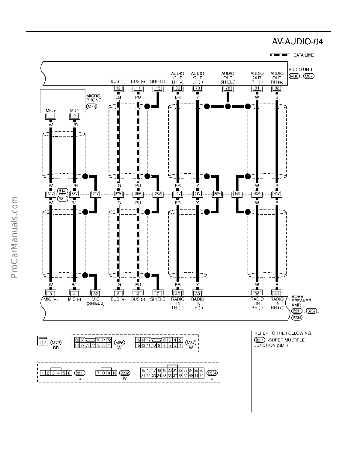
Audio unit is connected to BOSE speaker amp. as DATA LINE.
When the audio unit is turned to the ON position, audio signals are supplied.
● through audio unit terminals 12,11
● to BOSE speaker amp. terminals 5, 6.
When the audio unit is turned to the ON position, audio sound signals are supplied.
● through termin al s 79 , 80,8 1 an d 82 of au dio uni t
● to terminals 39, 40, 38 and 41 of the BOSE speaker amp.
● through terminals 30,14, 18, 19, 23, 22, 13, 29, 21, 20, 16, 17, 25, 24, 28 and 12 of the BOSE speaker
amp.
● to instrument panel speakers and the front and rear door speakers and woofer terminals 1 and 2.
A
B
C
D
E
F
G
H
I
J
AV
L
M
Revision; 2004 April 2003 Q45
AV-5

AUDIO
AV COMMUNICATION LINE
Audio system components (Audio unit, BOSE speaker amplifier, etc.) are connected by AV communication line
and controlled by signals from the multi-function switch.
AUDIOPILOT
AudioPilot ™ is the s ound improv ing system th at picks up a ny noises or t he sound of m usic coming into the
vehicle by a microp hone under the clock, an d that the BOSE speaker am p. revises the freque ncy feature of
music at real time in response to the frequency feature of the noise while driving and listening t o music.
● If low frequency area noise from vehicle is loud, it adjusts low frequency element of music to be bigger
than vehicle noise.
● If high frequency area noise from vehicle is loud, it adjusts high frequency element of music to be bigger
than vehicle noise.
● If vehicle noise is smaller than the setting volume, correction is not performed.
This compensate vehicle noise when listening to music.
TM
SYSTEM
Revision; 2004 April 2003 Q45
AV-6

AUDIO
Component Parts Location EKS006H4
A
B
C
D
E
F
G
H
I
J
AV
L
M
PKIA2227E
Revision; 2004 April 2003 Q45
AV-7

AUDIO
Schematic EKS0019M
TKWM0787E
Revision; 2004 April 2003 Q45
AV-8

AUDIO
Wiring Diagram — AUDIO — EKS0019N
A
B
C
D
E
F
G
H
I
J
AV
L
M
TKWM0788E
Revision; 2004 April 2003 Q45
AV-9

AUDIO
TKWM0789E
Revision; 2004 April 2003 Q45
AV-10

AUDIO
A
B
C
D
E
F
G
H
I
J
AV
L
M
TKWM0315E
Revision; 2004 April 2003 Q45
AV-11
AUDIO
TKWM0316E
Revision; 2004 April 2003 Q45
AV-12

AUDIO
A
B
C
D
E
F
G
H
I
J
AV
L
M
TKWM0370E
Revision; 2004 April 2003 Q45
AV-13

AUDIO
TKWM0371E
Revision; 2004 April 2003 Q45
AV-14

AUDIO
Wiring Diagram — REMOTE — EKS001RD
A
B
C
D
E
F
G
H
I
J
AV
L
M
TKWM0317E
Revision; 2004 April 2003 Q45
AV-15

AUDIO
TKWM0318E
Revision; 2004 April 2003 Q45
AV-16

AUDIO
Wiring Diagram — CD AUTO CHANGER — EKS001RE
A
B
C
D
E
F
G
H
I
J
AV
L
M
TKWM0790E
Revision; 2004 April 2003 Q45
AV-17

AUDIO
TKWM0791E
Revision; 2004 April 2003 Q45
AV-18

AUDIO
Terminals and Reference Value for BOSE Speaker Amplifier EKS000XT
Terminal No.
(Wire color)
+–
3 (W) 4 (R/L) Microphone Input ON
Item
Signal
input/
output
Ignition
switch
Condition
Operation
Microphone test
operate
Voltage
Example of symp-
tom
AudiopilotTM does
not operate properly.
PKIA2104E
A
B
C
D
E
5
(LG)
(PU)
Ground
6
Ground
7 - Shield ground - - - - -
11
Ground Battery power Input OFF - Battery voltage
(L)
Communication signal (+)
Communication signal (-)
Input/
output
Input/
output
ON -
SKIA0175E
ON -
SKIA0176E
13
29 (L/Y)
(P)
14
(G)
15 - Shield (sound) - - - - -
30 Shi el d (so und) - - - - -
Front door
speaker RH
output
Output ON
Receive radio
broadcast
SKIA0177E
System does not
work properly.
System does not
work properly.
System does not
operate.
No sound from
front door speaker
RH.
F
G
H
I
J
AV
L
M
16
17 (R/W)
(R/G)
Revision; 2004 April 2003 Q45
Rear door
speaker LH
output
Output ON
Receive radio
broadcast
SKIA0177E
AV-19
No sound from
rear Door speaker
LH.

AUDIO
Terminal No.
(Wire color)
+–
18
19 (W/G)
(L/Y)
21
(Y)
23
(G)
20 (L)
22 (R)
Item
Instrument
speaker LH
output
Instrument
speaker center output
Instrument
speaker RH
output
Signal
input/
output
Ignition
switch
output ON
output ON
output ON
Condition
Operation
Receive radio
broadcast
Receive radio
broadcast
Receive radio
broadcast
Voltage
Example o f symp-
tom
No sound from
Instrument
speaker LH.
SKIA0177E
No sound from
Instrument
speaker center.
SKIA0177E
No sound from
Instrument
speaker RH.
25
(P)
24 (PU)
Rear door
speaker RH
output
Output ON
27
Ground Ground - ON - Approx.0V -
(B)
28
(BR/W)12 (BR) Woofer output Output ON -
30
(R)
14 (G)
Front door
speaker LH
output
Output ON
Receive radio
broadcast
Receive radio
broadcast
SKIA0177E
No sound from
rear door speaker
RH.
SKIA0177E
No sound from
Woofer.
SKIA0177E
No sound from
front door speaker
LH.
SKIA0177E
31 - Shield (sound) - - - - 32 - Shiel d ( M ic) - - - - -
Revision; 2004 April 2003 Q45
AV-20

AUDIO
Terminal No.
(Wire color)
+–
34
(OR/L)Ground ACC power Input ACC - Battery voltage
40
41
(B)
39 (Y)
38 (W)
(BR)
Item
Audio sound
signal (LH)
Audio sound
signal (RH)
Signal
input/
output
Input ON
Input ON
Ignition
switch
Condition
Operation
Play cassette
tape.
Play cassette
tape.
Voltage
Example of symp-
tom
AV functions do not
operate.
Audio sound not
heard from LH
speaker.
SKIA0177E
Audio sound not
heard from RH
speaker.
SKIA0177E
Terminals and Reference Value for Audio Unit EKS000XU
Terminal No.
+-
Item
Signal
input/
output
Ignition
switch
Condition
Operation
Voltage
Example of symp-
tom
A
B
C
D
E
F
G
H
I
11 (PU) Ground
Communication signal (-)
12 (LG) Ground
13 - Shield ground - - - - 14 - Shield ground - - - - -
15 (R/L) Ground
Communication signal (+)
Communication signal (-)
Input/
output
Input/
output
Input/
output
ON -
ON -
ON -
SKIA0176E
SKIA0175E
SKIA0176E
System does not
work properly.
System does not
work properly.
System does not
work properly.
J
AV
L
M
Revision; 2004 April 2003 Q45
AV-21

AUDIO
Terminal No.
+-
16 (Y) Ground
52 (R/L) 51 (R/W)
54 (LG) 53 (PU)
Item
Communication signal (+)
CD sound
signal (LH)
CD sound
signal (RH)
Signal
input/
output
Input/
output
Ignition
Condition
switch
Operation
ON -
Input ON Play CD.
Input ON Play CD.
Voltage
Example of symp-
tom
System does not
work properly.
SKIA0175E
CD sound is not
heard from
speaker LH.
SKIA0177E
CD sound is not
heard from
speaker RH.
55 -
56 -
Shield ground
(signal)
Shield ground
(signal)
Communica-
58 (Y) Ground
59 (L) Ground
60 (G) Ground
tion signal
(CHG REQ)
Communication signal
(CHG-HU)
Communication signal
(HU-CHG)
SKIA0177E
-- - - -
-- - - -
CD auto changer
Input ON Insert/eject CD.
operation is not
possible.
SKIA0196E
CD auto changer
Input ON Insert/eject CD.
operation is not
possible.
SKIA0197E
CD auto changer
operation is not
possible.
Output ON
Press the CD
switch.
SKIA0198E
Revision; 2004 April 2003 Q45
AV-22

AUDIO
Terminal No.
+-
71 (R/L) Ground
72 (L/OR) Ground ACC power Input ACC - Battery voltage
73 (SB) Ground Battery power Input OFF - Battery voltage
75 (P/L) Ground
76 (SB)
Note1
(LG)
Note2
78 -
Ground
Item
Illumination
signal
Radio
antenna amp.
ON signal
Illumination
control signal
Shield
(Audio sound
signal)
Signal
input/
output
Input OFF
Output ON - Approx.10V or more
Input ON
Ignition
-- - - -
switch
Condition
Operation
Lighting switch
is ON (1st position).
Turn lighting
switch OFF. Approx. 3.0V or less
Illumination
control switch is
operated by
lighting switch
in 1st position.
Changes between approx. 0 and
Voltage
Battery voltage
approx. 12V.
Example of symp-
tom
Audio un it illumination does not
come on when
lighting switch is
ON (1st position).
Audio unit operation is not possible.
Cassette tape
player operation is
not possible.
Receiving status
of radio broadcast
becomes bad.
Audio un it illumination cannot be
controlled.
A
B
C
D
E
F
G
H
I
80 (BR) 79 (Y)
Audio sound
signal (LH)
Output ON
82 (B) 81 (W)
Audio sound
signal (RH)
NOTE:
1. With NAVI and for Canada with rear control switch.
2. Without NAVI.
Output ON
Play cassette
tape.
Play cassette
tape.
SKIA0177E
SKIA0177E
Audio sound is not
heard from
speaker LH.
Audio sound is not
heard from
speaker RH.
J
AV
L
M
Revision; 2004 April 2003 Q45
AV-23

AUDIO
Terminals and Reference Value for CD Auto Changer EKS0012U
Terminal No.
+-
2 (R/L) 1 (R/W)
4 (LG) 3 (PU)
6-
Signal
name
CD sound
signal (LH)
CD sound
signal (RH)
Shield
(CD sound
signal)
Signal
input/
output
Output ON Play CD.
Output ON Play CD.
Ignition
switch
-- - - -
Condition
Operation
Voltage Example of symptom
CD sound is not
heard from speaker
LH.
SKIA0177E
CD sound is not
heard from speaker
RH.
SKIA0177E
Communi-
8 (Y) Ground
cation signal (REQ)
Communi-
9 (L) Groun d
10 (G) Ground
12
13
Ground
Ground
(SB)
(SB)
cation signal (TXD)
Communication signal (RXD)
Battery
power
Illumination
control signal
Output ON Insert/eject t CD.
Output ON Insert/eject CD.
Input ON
Input OFF - Battery voltage
Input ON
Press the CD
switch.
illumination control switch is operated by lighting
switch in 1st position
Changer between approx. 0 and
approx.12V
CD auto changer
operation is not possible.
SKIA0196E
CD auto changer
operation is not possible.
SKIA0197E
CD auto changer
operation is not possible.
SKIA0198E
CD auto changer
operation is not possible.
-
Revision; 2004 April 2003 Q45
AV-24

AUDIO
Terminal No.
+-
14 (R/
15 (B) Ground Ground - ON - Approx. 0V -
16 (L/
OR)
Ground
L)
Ground ACC power Input ACC - Battery voltage
Signal
name
Illumination
signal
Signal
input/
output
Input OFF
Ignition
switch
Condition
Operation
Lighting switch is
ON (1st position)
Turn lighting
switch OFF
Voltage Example of symptom
Battery voltage -
Approx. 3.0V or less -
CD auto changer
operation is not possible.
Terminals and Reference Value for Rear Control Switch EKS001JO
TERMINALS
(+)
TERMINAL
1 L/Y Ground ACC Power ACC
12 B Ground Ground ON — Approx. 0V
WIRE
COLOR
(–)
ITEM
Ignition
switch
CONDITION
Operation
Rear control cancel
switch is ON
(position ON)
DATA (DC)
Ground battery voltage
A
B
C
D
E
F
G
H
10 Y Ground
Rear control switch
communication signal
ON
Operate the rear
control switch.
SKIA0199J
Terminals and Reference Value for Rear Control Cancel Switch EKS006H5
Terminal No.
+-
3 (G) Ground Acc power Output ACC
4 (P/B) Ground Acc power Input ACC - Battery voltage
Signal
name
Signal
input/
output
Ignition
switch
Condition
Operation
Rear control cancel switch is ON
(position ON)
Rear control cancel switch is OFF
(position CANCEL)
Voltage Example of symptom
Battery voltage -
Approx. 0V -
Rear control switch
operation does not
work.
Self-Diagnosis Function EKS006RK
DESCRIPTION
● Diagnosis function consists of the self-diagnosis mode, and the “CONFIRMATION/ADJUSTMENT” mode.
● Self-diagnosis mode checks for connection among audio unit, and CD auto changer and analyzes each
unit, then displays the res ults.
● “CONFIRMATION/A DJUSTMENT” function analyzes each speaker.(without nav igation system)
I
J
AV
L
M
Revision; 2004 April 2003 Q45
AV-25

AUDIO
DIAGNOSIS ITEM
Mode Description
● Check connection among AV and NA VI control unit or AV control unit and audio
Self-diagnosis
Confirmation/Adjustment
(without navigation system)
Speaker diagnosis
unit and CD Auto changer.
● Perform the unit diagnosis of audio unit and CD auto changer.
● Check the co nnection of each speaker using a test tone.
Self-Diagnosis Mode EKS001FA
OPERATION PROCEDURE
● To start the self-diagnosis mode and to check the diagnosis result, refer to AV-79, "Self-Diagnosis Mode"
for models with na vigation system, and DI-109, "Self-Diagnosis Mode" for vehicles w ithout navigation
system.
Confirmation/Adjustment Mode (without navigation system) EKS006RL
OPERATION PROCEDURE
1. Start the en gine.
2. Turn the audio system off.
3. While pressing the “INFO” switch, turn the volume control dial
clockwise or counterclockwise for 30 clicks or more. (When selfdiagnosis mode is aggravated, a short beep will be heard.)
● To return to the previous screen, press “PREV” switch.
4. The initial trouble diagnosis screen will be shown, and items
“Self-Diagnosis” and “Confirmation/Adjustment” will become
selective.
5. When “Confirmation/Adjustment” is selected on the trouble diagnosis screen, the operation will enter the Confirmation/Adjustment mode. In this mode, check and adjustment of each item
will become possible.
SKIA3512E
SKIA0381E
SKIA0361E
Revision; 2004 April 2003 Q45
AV-26

AUDIO
6. When “Speaker Test” is selected, the speaker diagnosis screen
will be shown. Then pre ss “Start/Next” and the test tone will be
emitted from one speaker. Press “Start/Next” again and the test
tone will be emitted from another speaker. Press “Stop” and the
test tone will be stopped.
NOTE:
Test tones emitted from each speaker ar e as follo ws.
A
B
Instrument
:1 KHz
speaker
Door speaker :1 KHz
Woofer :100 Hz
Trouble Diagnosis EKS000XY
● The majority of the audio troubles are the result of outside causes (bad CD/cassette, electromagnetic
interference, etc.). Check the inspection items below to diagnose the malfunction.
MALFUNCTION WITH RADIO, TAPE AND CD
Symptom Check items Possible cause
● Audio unit
Inoperative
No sound
Poor sound
Noisy -
● Make sure the ignition switch is in the ACC position.
● Make sure th e volume is not turned down.
● Make sure th e bal ance and fad er control knobs are
centered.
● Make sure th e bass and treble adjustment knobs are
centered.
FOR RADIO ONLY
Symptom Check items Possible cause
No sound
● Make sure the radio is tuned to a station's frequency.
● Audio unit pow er su ppl y circu it. Refer
to AV-30, "
Inspection" .
● Audio unit
● Audio unit pow er su ppl y circu it. Refer
to AV-30, "
Inspection" .
● Speaker
● Sound signal circuit between speaker
and audio unit
● Audio unit
● CD auto changer
● Speaker
● BOSE speaker amp.
● Audio unit
● CD auto changer
● Each electrical equipment
● BOSE speaker amp.
● Audio unit
● Antenna f eeder
● Antenna am plifier
● Glass antenna
Power Supply Circuit
Power Supply Circuit
C
SKIA3669E
D
E
F
G
H
I
J
AV
L
M
Revision; 2004 April 2003 Q45
AV-27

AUDIO
Symptom Check items Possible cause
● Make sure the radio is tuned to a station's frequency.
● Make sure the signa l of the recei ved station is not
weak.
Noisy
● Make sure no mirror-type window film nor any metal
object (after-market antenna, etc.) is attached on the
rear window glass (Note 1).
● Check w het her or not the m alfu nct io n occur s onl y in
a particular area. (Note 2)
Selected radio stations stored in
memory are deleted
-
NOTE:
1. The cause is a reduction in the receiving sensitivity of the window antenna.
2. This is noise resulting from variations in field strength, such as fading noise and multi-path noise, or external noise from trains and other sources. It is no t a malfunction.
● Fading noise: This noise occurs because of variations in the field strength in a narrow range due to moun-
tains or buildings blocking the signal.
● Multi-path noise: This noise results from the waves sent directly from the broadcast station arriving at the
antenna at a different time from the waves which refl ect off of mountains or b uildings.
● Audio unit
● Antenna fee der
● Antenna am plif ier
● window ant en na
● Noise prevention parts
● Each electrical equipment
● Wire harness of each piece of electri-
cal equip ment
● Audio unit
● Audio unit power supply circuit. Refer
to AV- 30, "Power Supply Circuit
Inspection" .
FOR CASSETTE PLAYER ONLY
Symptom Check items Possible cause
Cassette tape cannot be inserted.
Cassette tape cannot be ejected.
Auto reverse does not work, or the
tape direction changes in the middle
of play.
There is much noise.
The sound is not clear.
Sound fluctuates/tape speed not correct
No sound.
● Make sure a cassette tape is not already inserted.
● Make sure the cassette has no deformation or other malfunction.
● Make sure the cassette has no deformation or other malfunction.
● Make sure the cassette tape does not sag.
● There is a malfunct io n with tape wind ing . Make sure there is no
slack or other malfunction.
● Make sure an ol d cass ette tape is not bein g used.
● Make sure tha t the cassette tape itself does not have a lot of
noise, or that the tape does not have a low recording level.
● Make sure the tune is recorded on tape with Dolby B NR OFF and
played with Dolby B NR ON.
● Make sure the sound quality of the cassette tape itself is not poor.
● Make sure the re is no tape windin g ma lfunction, sagging, stretch-
ing, or other malfunction.
● Make sure there is no malfunction with the recording speed of the
cassette tape.
● Make sure the cassette tape has been recorded on.
Audio unit, audio unit
power circuit
Audio uni t
Revision; 2004 April 2003 Q45
AV-28

AUDIO
FOR CD ONLY
Symptom Check items Possible cause
CD cannot be inserted Make sure a CD is not already inserted.
CD cannot be ejected -
The CD cannot be played.
The sound skips, stops suddenly,
or is distorted.
● Make sure th e CD is not upside down.
● Make sure th ere is no dirt, dama ge, or wat er on the di sc.
● Make sure th ere is no dirt, dama ge, or wat er on the di sc.
● Make sure th e troubl e is not due to stro ng vi bra tion.
● CD auto changer
● CD auto changer
power circuit. Refer
to AV-30, "
Supply Circuit
Inspection"
CD auto changer
Power
A
B
C
D
Noise Inspection EKS000XZ
The vehicle itself can be a source of noise if noise prevention parts or electrical equipment is malfunctio n.
Check if noise i s c a us ed an d/or changed by en gi ne rotatio n, ignition switc h tu rne d to each position , a nd op eration of each piece of electrical equipment, and determine the cause.
NOTE:
The source of the noise can be found easily by listening to the noise while removing the fuses of electrical
components, one by one.
TYPE OF NOISE AND POSSIBLE CAUSE
Occurrence condition Possible cause
A continuous growling noise occurs. The speed of
the noise varies with changes in the engine speed.
Occurs only when engine is ON.
The occurrence of the noise is linked with the operation of the fu el pump .
Noise only occurs when various
electrical components are oper-
ating.
The noise occurs constantly, not just under certain conditions.
A cracking or snapping sound occurs while the veh icle is bei ng dr iven, especially
when it is vibrating excessively.
A whistling noise occurs while the engine speed is
high. A booming noise occurs while the engine is
running and the lighting switch is ON.
A cracking or snapping sound occurs with the
operation of various switches.
The noise occurs when various motors are operating.
● Malfunct i on w ith the ig nition condenser.
● Malfunct i on w ith the al ternat or
● Malfunct i on w ith the fu el pu mp condenser
● Relay malfunction, radio malfunction
● Malfunct i on w ith t he mo to r case grou nd
● Malfunct i on w ith the mo to r
● Rear wi ndow def ogge r coi l malfu nct io n
● Open ci rcu it in prin te d heat er
● Poor groun d of antenna amplifier or
antenna feeder line
● Mirror type film is attached on the rear win-
dow glass.
● After-mark et TV anten na and/ or electrical
accessories such as radio are attached on
the rear window glass.
● Malfunct i on w ith the gro und w i re of body
parts.
● Malfunction with ground due to part installa-
tion malfunction.
● Malfunct i on w ith wi ring connections or a
short circuit
E
F
G
H
I
J
AV
L
M
Revision; 2004 April 2003 Q45
AV-29

AUDIO
Power Supply Circuit Inspection EKS000Y0
1. CHECK FUSE
● Make sure the following fuses of the BOSE speaker amplifier, audio unit, CD auto changer and rear con-
trol cancel switch are not blown. Refer to PG-66, "
"FUSE, FUSIBLE LINK AND RELAY BOX" .
Terminals
Unit
Connector Terminal (Wire color)
BOSE speaker amplifier
Audio uni t
CD auto changer
B233 11 (L) Ground Battery power J
B234 34 (OR/L) Ground ACC power 21
M86 73 (SB) Ground Battery power 52
M86 72 (L/OR) Ground ACC power 21
M109 12 (SB) Ground Battery power 5 2
M109 16 (L/OR) Ground ACC power 21
OK or NG
OK >> GO TO 2.
NG >> If fuse is bl ow n be s ure to eliminate cause of malfunction befo re i ns tallin g new fuse. Refer to PG-
2, "POWER SUPPLY ROUTING" .
FUSE BLOCK - JUNCTION BOX (J/B) NO.1" .PG-69,
(-)
Signal name Fuse No.(+)
Revision; 2004 April 2003 Q45
AV-30

AUDIO
2. CHECK POWER SUPPLY CIRCUIT
Disconnect the each unit connector. Check voltage between the following harness connector terminal (+) and ground (-).
Terminal No.
(+)
Unit
BOSE
speaker
amplifier
Audio unit
CD Auto
changer
Connector
B233 11 (L) Ground
B234 34 (OR/L) Ground
M86 73 (SB) Ground
M86 72 (L/OR) Ground
M109 12 (SB) Ground
M109 16 (L/OR) Ground
Terminal
(Wire
color)
(-)
OK or NG
OK >> Inspection end.
NG >> Check harness for open or short between each unit and
fuse or fusible link.
Power
Source
Battery
power
ACC
power
Battery
power
ACC
power
Battery
power
ACC
power
Ignition
switch
OFF
ACC
OFF
ACC
OFF
ACC
Reference
voltage (V)
Battery
voltage
Battery
voltage
Battery
voltage
Battery
voltage
Battery
voltage
Battery
voltage
A
B
C
D
E
F
G
H
I
Audio System Does Not Turn On EKS000Y1
1. SELF-DIAGNOSIS
1. Perform self-d ia gn os is . Ref e r t o AV-79, "
109, "Self-Diagnosis Mode" for models without navigation system.
OK or NG
OK >> Replace audio unit.
NG >> Check the malfunctioned area according to the self-diagnosis result.
Steering Switch Does Not Operate EKS001JP
Self-Diagnosis Mode" for models with navigation system and DI-
1. SELF-DIAGNOSIS MODE OF MULTI-FUNCTION SWITCH
1. Carry out the self-diagnosis mode in the self-diagnosis function.
2. Push steering switch.
Beep sound should operate.
OK or NG
OK >> GO TO 2.
NO >> GO TO 3.
J
AV
SKIA3614E
L
M
Revision; 2004 April 2003 Q45
AV-31

AUDIO
2. SELF-DIAGNOSIS MODE OF AV COMMUNICATION LINE
1. Carry out the self-dia gnosis mode in the self-diagn osis function. Refer to AV -7 9 , "
Self-Diagnosis Mode"
(with navigation system) or refer to DI-109, "Self-Diagnosis Mode" .
Dose self
–diagnosis start?
YES >> With self-diagnosis results, check the malfunction part.
NO >>
● Check multi-function sw it ch of p owe r su pp ly a nd gro un d c irc uit ch ec k. Ref e r t o DI-121, "Inspec-
tion of Multifunction Switch for Power Supply and Ground Circuit" .
● Check harness between multi-function switch and AV and NAVI control unit or AV control unit.
3. CHECK STEERING SWITCH CIRCUIT
1. Turn ignition switch OFF.
2. Disconnect steering switch connector and multi-function switch connector.
3. Check the following.
– Con tin uity between stee rin g switch harness con ne ctor M4 44 terminal 2 (L) and mul ti-fu nc ti on switch har-
ness connector M83 terminal 7 (GY/L).
– Continuity between steering switch harness connector M444 terminal 2 (L) and ground.
Terminals
(+) (–)
Connector
M444 2 (L) M8 3 7 (GY/L) Yes
M444 2 (L) Ground No
Terminal
(Wire color)
Connector
OK or NG
OK >> GO TO 4.
NG >> Check the following.
● Harness between for open or short steering switch and spiral cable.
● Connector housing terminal for disconnection and loose ness.
4. CHECK HORN OPERATION
Terminal
(Wire color)
Continuity
SKIA0537E
1. Check horn operation.
Horn should operate.
OK or NG
OK >> GO TO 5.
NG >> Check horn system .
5. CHECK POWER SUPPLY CIRCUIT
1. Connect steering switch connector.
2. Turn the ignition switch ON.
3. Check harness between steering switch harness connector
M444 terminal 1(R) and ground.
Battery voltage should exist.
OK or NG
OK >> GO TO 6
NG >> Check harness for open or short between steering
switch and horn relay [located in fuse, fusible link and
relay block (J/B)]
Revision; 2004 April 2003 Q45
AV-32
SKIA0538E

AUDIO
6. CHECK STEERING SWITCH GROUND CIRCUIT
1. Disconnect steering switch connector.
2. Check harness between steering switch harness connector
M444 terminal 3 (B) and ground.
Continuity should exist.
OK or NG
OK >> Replace steering switch.
NG >> Repair or replace harness.
SKIA0539E
Rear Control Switch Audio Operation Does Not Work EKS001JQ
1. CONFIRM OF OPERATION
1. Is it activated by normal audio operation?
YES or NO
YES >> GO TO 2.
NO >> Refer to AV-31, "
Audio System Does Not Turn On"
2. SELF-DIAGNOSIS
1. Carry out th e self-diag nosis mode in the self -diagnosi s function . For models wit h navigation , refer to AV-
79, "Self-Diagnosis Mode" , and for models without navigation, refer to DI-109, "Self-Diagnosis Mode" .
Is the self-diagnosis result OK?
OK >> GO TO 3.
NG >> With self-diagnosis results, check the faulty part.
3. REAR CONTROL SWITCH OPEN OR SHORT CIRCUIT
A
B
C
D
E
F
G
H
I
J
1. Turn ignition switch OFF.
2. Disconnect rear control switch connector and multi-function switch con n ector.
3. Check the following.
– Continuity harness between rear control switch harness connector B502 terminal 10(Y) and multi-func-
tion switch harness connector M83 terminal 8 (Y).
– Continuity between rear control switch harness connector B502 terminal 10 (Y) and ground.
Terminals
(+) (–)
Connector
B502 10 (Y) M83 8 (Y) Yes
B502 10 (Y) Ground No
Terminal
(Wire color)
Connector
Terminal
(Wire color)
Continuity
OK or NG
OK >> Replace rear control switch.
NG >> Repair or replace harness.
AV
L
M
SKIA0540E
Revision; 2004 April 2003 Q45
AV-33

AUDIO
Rear Control Switch Operation Does Not Work EKS006FL
1. CONFIRM STATUS OF REAR CONTROL CANCEL SWITCH
1. Is rear control cancel swit ch in the status of cancel?
YES or NO
YES >> After turning on the switch reconfirm the status.
NO >> GO TO 2.
2. POWER SUPPLY CIRCUIT CHECK 1
1. Disconnect rear control cancel switch con nector.
2. Turn the ignition switch ACC.
3. Check voltage between rear control cancel switch harness connector R16 terminal 4 (P/B) and ground.
4 – Ground :Battery voltage
OK or NG
OK >> GO TO 3.
NG >> Check harness for open or short between rear control
cancel switch and fuse.
3. CHECK REAR CONTROL CANCEL SWITCH
1. Turn ignition switch OFF.
2. Check between rear control cancel switch harness connector
terminal 3 and 4.
Connector Terminal Condition Continuity
When press "ON" Should exist
R16 3 4
OK or NG
OK >> GO TO 4.
NG >> Replace rear control cancel switch.
When press
"CANCEL"
Should not exist
4. HARNESS CHECK 1
1. Disconnect rear control cancel relay.
2. Check continuity between rear control cancel switch harness
connector R16 terminal 3(G) and rear control cancel relay harness connector B253 terminal 2(G).
3 – 2 :Continuity should exist
SKIA3656E
SKIA3657E
3. Check continuity between rear control cancel switch harness
connector R16 terminal 3 (G) and ground.
3 – Ground :Continuity should not exist
OK or NG
OK >> GO TO 5.
NG >> Repair or replace harness.
Revision; 2004 April 2003 Q45
AV-34
SKIA3660E

AUDIO
5. CHECK REAR CONTROL CANCEL RELAY GROUND CIRCUIT
1. Check continuity rear control cancel relay harness connector
B253 terminal 1 (B) and ground.
1 – Ground :Continuity should exist
OK or NG
OK >> GO TO 6.
NG >> Repair or replace harness.
6. REAR CONTROL CANCEL RELAY CHECK
1. Supply 12V current between rear control cancel relay 1 and 2.
2. Check continuity between rear contr ol cancel relay 3 and 5.
3 – 5 :Continuity should exist
OK or NG
OK >> GO TO 7.
NG >> Replace rear control cancel relay.
A
B
C
D
SKIA3664E
E
F
G
H
7. POWER SUPPLY CIRCUIT CHECK 2
1. Turn the ignition switch ACC.
2. Check voltage between rear control cancel relay harness con nector B253 terminal 3 (L/OR) and ground.
OK or NG
3 – Ground :Battery voltage
OK >> GO TO 8.
NG >> Check harness for open or short between rear control
cancel relay and fuse.
8. HARNESS CHECK 2
1. Turn ignition switch OFF.
2. Disconnect rear control switch connector.
3. Check continuity between rear control switch harness connector
B502 terminal 1 (L/Y) and rear control cancel relay harness connector B253 ter m inal 5 (L/Y).
SKIA3662E
SKIA3663E
I
J
AV
L
M
1 – 5 :Continuity should exist.
4. Check continuity between rear control switch harness connector
B502 terminal 1 (L/Y) and ground.
1 – ground :Continuity should not exist.
OK or NG
OK >> Replace rear control switch.
NG >> Repair or replace harness.
Revision; 2004 April 2003 Q45
AV-35
SKIA3666E

AUDIO
AudioPilot™ Does Not Work EKS006DH
1. CHECK MICROPHONE SIGNAL
1. Turn ignition switch ON.
2. Check voltage signal between BOSE speaker amp. harness
connector B231 termin al 3 (W) and 4 (R/L) with CO NSULT-ll or
oscilloscope, when inputting some sounds (voice, etc.) toward
the microphone.
3 – 4
PKIA2104E
Does the voltage signal change with sounds ?
Yes >> Replace BOSE speaker amp.
No >> GO TO 2.
2. MICROPHONE CIRCUIT CHECK 1
1. Turn ignition switch OFF.
2. Disconnect BOSE speaker amp. and microphone connector .
3. Check continuity between BO SE sp eake r amp. ha rne ss con nector B231 term inal 3 (W) a nd mic ropho ne har nes s conn ecto r M73
terminal 1 (W).
Continuity should exist.
4. Check continuity between BO SE sp eake r amp. ha rne ss con nector B231 terminal 3 (W) and ground.
Continuity should not exist.
OK or NG
OK >> GO TO 3.
NG >> Repair or replace harness.
3. MICROPHONE CIRCUIT CHECK 2
SKIA3615E
SKIA3616E
1. Check continuity between BO SE sp eake r amp. ha rne ss con nector B231 terminal 4 (R/L) and microphone harness connector
M73 terminal 2 (L/R).
Continuity should exist.
2. Check continuity between BO SE sp eake r amp. ha rne ss con nector B231 term inal 4 (R/L) and ground.
Continuity should not exist.
OK or NG
OK >> Replace microphone.
NG >> Repair or replace harness.
Revision; 2004 April 2003 Q45
AV-36
SKIA3617E

AUDIO
Removal and Installation of Audio Unit EKS000Y3
REMOVAL
1. Remove glove box assembly. Refer to IP-15, "GLOVE BOX
ASSEMBLY"
2. Remove screws (2) and remove audio unit.
SKIA3548E
A
B
C
D
INSTALLATION
Install in the reverse order of removal .
Removal and Installation of CD Auto Changer EKS0012V
REMOVAL
1. Remove cluster lid center lower. Refer to IP-11, "WORK STEPS" .
2. Remove console box as semb ly. Refer to IP-1 1, "
.
3. Remove screws (4) and remove CD Auto changer.
WORK STEPS"
INSTALLATION
Install in the reverse order of removal .
Removal and Installation of Door Speaker EKS000Y4
REMOVAL
1. Remove door finisher. Refer to EI-30, "DOOR FINISHER" .
2. Remove screws (3) and remove speaker.
E
F
G
H
I
SKIA3549E
J
AV
L
PKIA0231E
INSTALLATION
Install in the reverse order of removal .
Removal and Installation of Instrument Panel Speaker EKS0012T
REMOVAL
1. Remove instrument panel. Refer to IP-10, "INSTRUMENT PANEL ASSEMBLY" .
Revision; 2004 April 2003 Q45
AV-37
M

AUDIO
2. Remove screws (4) and remove instrument panel speaker.
SKIA0353E
INSTALLATION
Install in the reverse order of removal.
Removal and Installation of Woofer EKS000Y7
REMOVAL
1. Remove rear parcel s helf finisher. Refer to EI-39, " REAR PAR-
CEL SHELF FINISHER" .
2. Remove screws (4) and remove woofer.
INSTALLATION
Install in the reverse order of removal.
Removal and Installation of BOSE Speaker Amplifier EKS000Y8
REMOVAL
1. Remove trunk trim. Refer to EI-52, "TRUNK ROOM TRIM &
TRUNK LID FINISHER" .
2. Remove rear parcel s helf finisher. Refer to EI-39, " REAR PAR-
CEL SHELF FINISHER" .
3. Remove screws (4 ) and remove BOSE speaker amplifier from
the trunk room side.
INSTALLATION
Install in the reverse order of removal.
SKIA0356E
SKIA0357E
Revision; 2004 April 2003 Q45
AV-38

AUDIO
Removal and Installation of AudioPilot™ Microphone EKS006CH
REMOVAL
1. Remove cluster lid C. Refer to IP-13, "CLUSTER LID C" .
2. Remove clock. Refer to DI-164, "
TM
3. Disconnect AudioPilot
4. Remove screws (2) and re move AudioPilot
microphone connector.
Removal and Installation" .
TM
microphone.
SKIA3550E
A
B
C
D
INSTALLATION
Install in the reverse order of removal .
Removal and Installation of Steering Wheel Switch EKS001HQ
Refer to SRS-39, "DRIVER AIR BAG MODULE" .
Removal and Installation of Rear Control Switch EKS001HR
REMOVAL
1. Remove the tra y box from the c enter armrest. Ref er to SE-202,
"CENTER SEATBACK ASSEMBLY" .
2. Remove the rear cont rol switch from the tray box.
INSTALLATION
Install in the reverse order of removal .
Removal and Installation of Rear Control Cancel Switch EKS006CI
REMOVAL
1. Remove front interior lamp. Refer to LT-107, "Removal and
Installation" .
2. Remove rear control cancel switch from front interior lamp.
E
F
G
H
I
J
SKIA0390E
AV
L
M
SKIA3551E
INSTALLATION
Install in the reverse order of removal .
Revision; 2004 April 2003 Q45
AV-39

AUDIO ANTENNA
AUDIO ANTENNA PFP:28200 Wiring Diagram — W/ANT — EKS001FC
TKWM0320E
Revision; 2004 April 2003 Q45
AV-40

AUDIO ANTENNA
Location of Antenna EKS000YO
A
B
C
D
E
F
G
PKIA0241E
Window Antenna Repair EKS001FD
ELEMENT CHECK
1. Attach prob e circuit tester (in ohm range) to antenna terminal on
each side. If an elem ent is OK , cont inui ty should exis t. If an ele -
ment is broken, no continuity should exist.
H
I
J
AV
L
M
SEL250I
Revision; 2004 April 2003 Q45
AV-41

TELEPHONE (PRE WIRE)
TELEPHONE (PRE WIRE) PFP:28342 Wiring Diagram — PHONE — EKS006SO
TKWM0440E
Revision; 2004 April 2003 Q45
AV-42
NAVIGATION SYSTEM
NAVIGATION SYSTEM PFP:25915
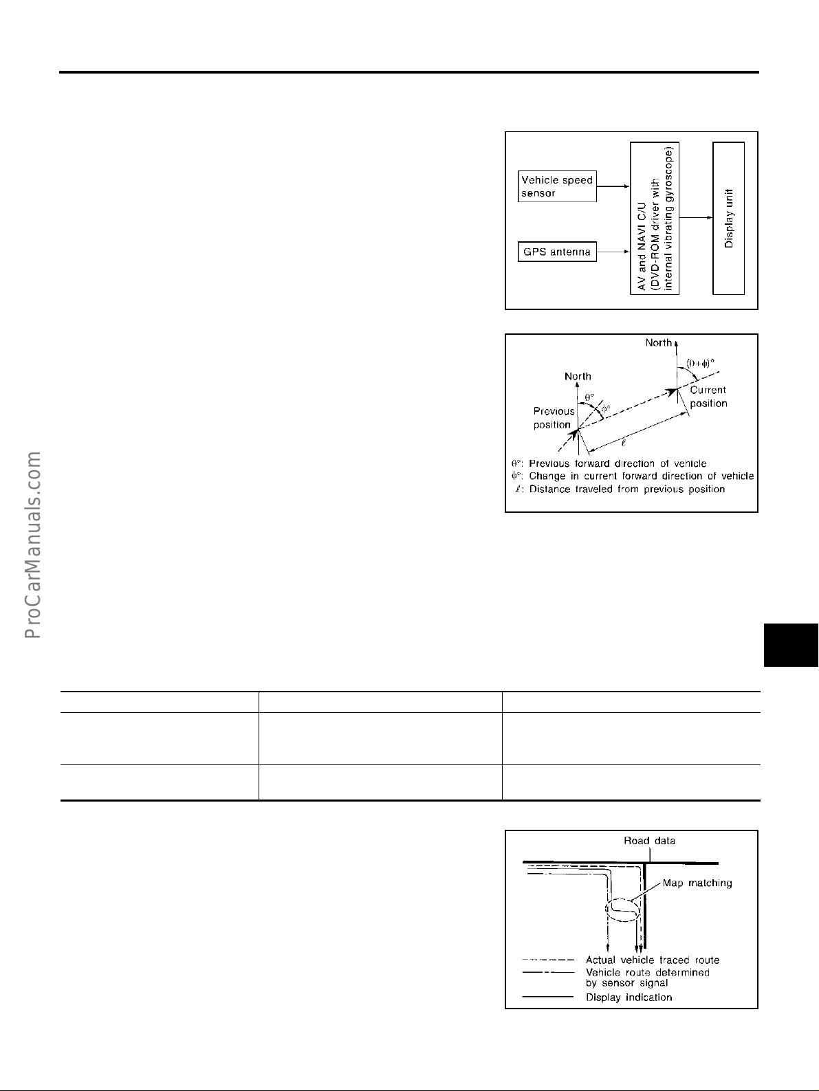
System Description EKS001LN
The navigation system periodically calculates the vehicle's current
position according to the following three signals: Travel distance of
the vehicle a s det er m ined by th e v eh ic le sp ee d s en so r, turn i ng an gle
of the vehicle as determ in ed by th e gy ros co pe (ang ul ar ve lo city sensor), and the direction of vehicle travel as determined by the GPS
antenna (GPS information).
The current pos ition of th e vehicl e is th en id entif ied by comp ari ng th e
calculated veh icle position with m ap data read from the ma p DVDROM, which is stored in the DVD-ROM drive (map-matching), and
indicated on the screen with a current-location mark.
SKIA3971E
By comparing the vehicle position detection results found by the
GPS and by map-matc hing, more accurate vehicle positio n d ata can
be used.
The current vehicle position will be calculated by detecting the distance the vehicle moved from the previous calculation point and its
direction.
A
B
C
D
E
F
G
TRAVEL DISTANCE
Travel distance calculations are based on the vehicle speed sensor input signal. Therefore, the calculation
may become inco rrec t as th e tire s wear d own . To prevent this, an automatic distance fi ne adj ustm en t fu nc tio n
has been adopted.
TRAVEL DIRECTION
Change in the travel direction of the vehicle is calculated by a gyroscope (angular velocity sensor) and a GPS
antenna (GPS informati on). As the gyroscope and G PS antenna have both meri t and demerit, input sign als
from them are prioritized in each situation. However, this order of priority may change in accordance with more
detailed travel conditions so that the t ravel direction is detected more accurately.
Type Advantage Disadvantage
● Direction errors may accumulate when the
vehicle is driven for long dista nce s wit hout
stopping.
● Correct direc tion cannot be detected when
the vehicle speed is low.
Gyroscope (angular velocity sensor)
GPS antenna (GPS information)
● Can dete ct the vehicle's turning angle
quite accurately.
● Can de te ct the vehicle's travel direction
(North/South/East/West).
MAP-MATCHING
Map-matching is a function that re positions the ve hicle on the road
map when a ne w loc ation i s judg ed to b e the m ost ac curate. This is
done by comparing the current vehicle position, calculated by the
method described in the position detection principle, with the road
map data around the vehicle, read from the map DVD-ROM stored in
the DVD-ROM drive.
Therefore, the vehicle position may not be corrected after the vehicle
is driven over a certain di stance or time in whic h GPS informa tion is
hard to receive. In this case, the current-location mark on the display
must be corrected manually.
CAUTION:
The road map data is based on data stored in the map DVDROM.
H
SEL684V
I
J
AV
L
M
SEL685V
Revision; 2004 April 2003 Q45
AV-43

NAVIGATION SYSTEM
● In map-matching , altern ative ro utes to reach the de stinati on will
be shown and prioritized, after the road on which the vehicle is
currently driven has been judged and the current-loca tion mark
has been repositio ne d.
If there is an error in distance and/or d irection, the alternative
routes will be shown in different order of priority, and the wrong
road can be avoided.
If two roads are runn ing in parallel, they a re o f th e s am e pri ority.
Therefore, the current-location mark may appear on either of
them alternately, depending on maneuvering of the steering
wheel and configuration of the road.
● Map-matching does not function correctly when the road on
which the vehicle is driving is new and not recorded in the map
DVD-ROM, or when the road patter n stored in the map data and
the actual road pattern are different due to repair.
When driving on a roa d not p resen t in the map, th e map -matc hing function may find another road and position the current-location mark on it. Then, when the correct road is detected, the
current-location mark may leap to it.
● Effective range for comparing the vehicle position and travel
direction calculat ed by the distance and directi on with the road
data read from the map DVD-ROM is limited. Therefore, when
there is an excessive gap between the current vehicle position
and the position on the map, correction by map-matching is not possible.
SEL686V
SKIA0613E
GPS (GLOBAL POSITIONING SYSTEM)
GPS (Global Positioning System) has been developed and controlled by the US Department of Defense. The system utilizes GPS
satellite (N AVSTAR ), send in g ou t ra di o wav es w hil e f l yi ng o n an orbi t
around the earth at the height of approx. 21,000 km (13,000 mil es).
The GPS receiver c alculates the vehicle's positi on in three dimensions (latitude/longitude/altitude) according to the time lag of the
radio waves received from four or more GPS satellites (three-dimen-
sional positioning). If radio waves were received only from three
GPS satellites , the GPS rece iver calculate s the vehicl e's positio n in
two dimensions (latitude/longitude), u tilizing the altitude data ca lculated previou sly by us ing radio waves fr om four o r more GPS satellites (two-dimensional positioning).
Accuracy of the GPS will deteriorate under the following conditions.
● In two-dimensional positioning, the GPS accuracy will deteriorate when the altitude of the vehicle position
changes.
● There may be an e r ror o f ap pr o xi mate ly 10 m (30 ft ) i n po si ti on d et ec t ed by thr ee -di me ns io na l posi ti o ni ng ,
which is more ac cu rate than two-dim ensional posit ion ing. The accurac y c an be even low er de pe nd in g on
the arrangement of the GPS satellites utilized for the positioning.
● Position detection is no t possible when the vehicle is in an area whe re radio waves from the GPS sat ellite
do not reach, such as in a t unnel, park ing lot in a build ing, and under an elevat ed high way. Radio waves
from the GPS satellites may not be received when some object is located over the GPS antenna.
● Position correction by GPS is not available while the vehicle is stopped.
SEL526V
Revision; 2004 April 2003 Q45
AV-44

NAVIGATION SYSTEM
COMPONENT DESCRIPTION
AV and NAVI Control Unit
● The gyro (angular speed sensor) and the DVD-ROM drive are
built-in units that control the nav ig ati on func ti ons.
● Signals are received from the gyro, the vehicle speed sensor,
and the GPS antenna. Vehicle location is determined by combining this data with the data contained in the DVD-ROM map.
Locational information is shown on liquid crystal display panel.
A
B
C
D
PKIA0248E
DVD-ROM Drive
Maps, traffic control regulati ons, and other pertinent inform ation can
be easily read from the DVD-ROM disc.
Map DVD-ROM
● The map DVD-ROM has maps, traffic control regulations, and other pertinent information.
● To improve DVD-ROM map matching and route determination functions, the DVD-ROM uses an exclusive
Nissan format. Therefore, the use of a DVD-ROM provided by other manufacturers cannot be used.
Gyro (Angular Speed Sensor)
● The oscillator gyro sensor is used to detect changes in vehicle steering angle.
● The gyro is built into the navigation (NAVI) control unit.
BIRDVIEW
The BIRDVIEW™ provides a detailed and easil y s een display of road conditions covering the vehicle's immediate to distant area.
● MAP DISPLAY
™
E
F
G
H
PKIA0249E
I
J
AV
L
M
SKIA0542E
Revision; 2004 April 2003 Q45
AV-45

NAVIGATION SYSTEM
● BIRDVIEW
™
Description
● Display area: Trapezoida l representation showing appr oximate
distances (Wn, D, and Wd).
● Ten horizontal grid lines ind icate display width while six ve rtical
grid lines indicate display depth and direction.
● Drawing line area shows open space, depth, and immediate
front area. Each area is to a scale of approximately 5:6:25.
● Pushing the “ZOOM IN” button during operation displays the
scale change and the view point height on the left side of the
screen.
The height of the view point increases or decreases when
“ZOOM” or “WIDE” is selected with the joystick.
SKIA0544E
MAP DISPLAY
Function of each icon is as follows:
1. Azimuth indication.
2. Position marker.
– Th e tip of th e arro w show s th e curren t pos ition . The shaft of the
arrow indicates the direc tion in which the vehicle is tr aveling.
3. GPS reception signal (indicates current reception conditions).
4. Distance display (shows the distance in a redu ced scale).
SEL691V
SKIA0545E
Revision; 2004 April 2003 Q45
AV-46

NAVIGATION SYSTEM
FUNCTION OF MULTIFUNCTI ON SWITCH
Display with Pushed “DEST” Switch
● Easy Mode
A
B
C
D
SKIA3509E
● Expert Mode
The function of each icon is as follows:
Icon
Address Book × Favorite place can be saved to memor y.
Address/Street ××The destination can be searched from the address.
Point of Interest (POI) ××The destination of favorite facility can be searc hed.
Previous Dest. × The previous ten destinat io ns st ore d in mem or y are displayed.
Intersection × The destination can be searched from the inter sect i on.
City × The destination can be searched from ci ty na me .
Map × The destination can be searched from the map .
Phone Number ×
Home × Sets the home as a destination.
Help × Explanation of navigational functions appea r on the dis pl ay.
Country ××Select country (USA, CANADA)
MODE
Easy Expert
Description
When two or more countries are included in one DVD-ROM, the destination can be
searched for under the country name.
SKIA3510E
E
F
G
H
I
J
AV
L
M
Revision; 2004 April 2003 Q45
AV-47

NAVIGATION SYSTEM
Display with Pushed “ROUTE” Switch
● Easy Mode
● Expert Mode
SKIA0548E
The function of each icon is as follows:
Icon
Quick Stop ××
Where am I? ××N ext , cu rrent and pre vi ous st re et na me s can be di spl ay ed.
Route Info.* ×
Edit Route* ×
Help × Explanation of navigational functions appear on the display.
*: When destinations have b een en te red , r oute gui dance has been turned OFF or des tinati on has been reached, “Route Info.” and “Edit
Route” are not displayed.
MODE
Easy Expert
Description
The selected facility is set as the destination or waypoint .
(Route guidance has been turned OFF or the destinat io n has bee n reached)
The following items can be set.
● Complete Route
● Turn List
● Route Simulation
(Displayed only when the destination area has been set.)
Change the destination or add the transit points of the route set in the route guide. (Dis-
played only when the automatic reroute function has been turned OFF and the recommended route is not followed.)
SKIA0549E
Revision; 2004 April 2003 Q45
AV-48

NAVIGATION SYSTEM
Display with Pushed “SETTING” Switch
The function of each icon is as follows:
Icon Description
Audio
Display Settings of display can be perfor me d.
Vehicle Electronic Systems Settings of vehicle electrical equipment can be performed.
Navigation Settings and adju st ing of nav ig ation can be performed.
Short Menus Easy Mode and Expert Mode ca n be sw itched.
Guidance Volume The volume and/or on/off of voice prompt can be controlled by the joys tick .
Help (only easy mode) Explanation of navigational function s appear on the display.
Sound quality can be adjusted, and also ON/OFF set t ing of switc h beep so und can be performed.
Noise compensation ON/OFF setting can be performed.
A
B
C
SKIA0550E
D
E
F
G
H
I
J
AV
L
M
Revision; 2004 April 2003 Q45
AV-49

Navigation Setting
How To Perform Navigation Setting
1. Start the en gine.
2. Push “SETTING” switch.
3. Select “NAVIGATION”.
Application Items
NAVIGATION SYSTEM
SKIA0551E
Icon Description
View Map display mode can be switched. AV-50
Heading
Nearby Display Icons
Save Current Location Current vehicle location can be registered in Addres s Book. AV-51
Adjust Current Location
Auto Re-route ON/OFF ON/OFF of Auto Re-route can be switched. AV-51
Avoid Area Setting A particular area can be avoided when routing. AV-52
Clear Memory Address book, prev io us destination or avoid area can be deleted. AV-54
Edit Address Book Address book can be edited. AV-52
GPS Information
Quick Stop Customer Setting One facility of your selection can be added to your Quick Stop. AV-51
Set Average Speed for Estimated
Journey Time
Tracking Tracking to the present vehicle position can be displayed. AV-52
Heading of the map display can be customized for either north heading or the
actual driving direction of the vehicle.
Icons of facilities can be displayed.
Facilities to be displayed can be selected from th e var iety selections.
Current location of position marker can be adjusted. Direction of position marker
also can be calibrated when heading direction of the vehi cle on th e dis pla y is
not matched with the actual direction.
The GPS data includes longitude, latitude and altitude (distance above sea
level) of the present vehicle position, and current date and time for the area in
which the vehicle is being driven.
Also indicated are the GPS reception conditions and the GPS satellite position.
Average vehicle speed can be set to calibrate estimat ed journey time for the
destination.
Reference
page
AV-52
AV-53
AV-53
AV-51
AV-53
“VIEW” MODE
1. Select “BIRDVIEW™” or “Plan View” icon.
● To open the map screen display with BIRDVIEW™, select
“BIRDVIEW™”.
● To open the map screen display with Plan View, select “Plan
View”.
SKIA0554E
Revision; 2004 April 2003 Q45
AV-50

NAVIGATION SYSTEM
“GPS INFORMATION” MODE
● Latitude, l on gi tud e, altitude, as tro me tri c s tate, and satelli te lo ca -
tion are displayed as GPS information.
NOTE:
Altitude is displayed only in three-dimensional status.
A
B
C
“SAVE CURRENT LOCATION” MODE
● The current vehicle location can be registered in “Address
Book”.
NOTE:
“Address Book” can store 50 items max.
“QUICK STOP CUSTOMER SETTINGS” MODE
● Select a category for the “Quick Stop” menu.
SKIA0555E
SKIA0556E
D
E
F
G
H
I
J
AV
SKIA0557E
“AUTO RE-ROUTE” MODE
● To activate “AUTO RE-ROOT” mode, select “On”.
● To disactivate “AUTO RE-ROOT” mode, select “Off”.
SKIA0558E
Revision; 2004 April 2003 Q45
AV-51
L
M

NAVIGATION SYSTEM
“AVOID AREA SETTINGS” MODE
● Areas to avoid can be registered.
“TRACKING” MODE
● To delete the tracking marks on, select “Off”.
● To leave the tracking marks on map, select “On”.
NOTE:
When a trail disp lay i s turn ed OFF, trail data is erase d fr om the me mory.
SKIA2058E
“EDIT ADDRESS BOOK” MODE
● Edit the items registered in Address Book.
“HEADING” MODE
● To display North up, select “North up”.
● To display the car heading up, select “Heading up”.
SKIA0559E
SKIA3511E
SKIA0561E
Revision; 2004 April 2003 Q45
AV-52

NAVIGATION SYSTEM
“NEARBY DISPLAY ICONS” MODE
● Select an icon to display on the map screen.
A
B
C
“ADJUST CURRENT LOCATION” MODE
1. Select an ic on“right” or “left” to calibrate the heading di rection.
(Arrow marks will rotate correspond in g to the cal ibr ation key.)
2. Select “Set” . Then the vehi cle mark will be matched to the arrow
mark.
SKIA0562E
SKIA0563E
D
E
F
G
H
I
J
AV
SKIA0564E
“SET AVERAGE SPEED” MODE
● Set the average vehicle speed to calibrate the estimated journey
time for the destination.
● Set three items; “Freeway”, “Main Roads”, and “Ordinary
Roads”.
SKIA0565E
Revision; 2004 April 2003 Q45
AV-53
L
M

NAVIGATION SYSTEM
“CLEAR MEMORY” MODE
● To delete all the stored places in “Address Book”, “Avoid Area”
and “Previous Dest”, select “Yes”.
GUIDANCE VOLUME
Description
Following guidance volume setting can be chan ged.
SKIA3572E
Activation/Deactivation Setting
● The voice pro mpt can be turned on/off by pressing the “Guidance Volume” button.
Voice Volume Setting
● Volume of the voice can be controlled by bending the joystick to left/right.
Precautions for AV and NAVI Control Unit Replacement EKS001LO
● When replacing the A V and NAVI control unit, eject the map DVD-ROM before disconnecting the battery.
● The AV and NAVI cont r ol un it ha s the fo ll o win g in fo rma t io n stor e d in it s mem or y. Record the memory con-
tents bef o re replacing the control un it, and input them in the new unit as necessary.
<FM·AM> ● Preset frequ enc y
● Area for indicating station, selection of overlapped stations
<CD>
<Sound quality>
<Image quality>
<Navigation mode>
● Program status
● Volume balance memory set values
● Equalize r me mo ry set value s
● Brightness of light when ON/OFF
● Dimming switching
● Display color switching
● Latest status (map screen/BIRDVIEW™, reduced scale, rotation angle
of map screen, route guide ON/OFF, track ON/OFF, etc.)
● Current position
● Destination, passing poi nt 1 - 5
● Registered places, their names, etc.
SKIA0567E
NOTE:
Only removing the battery does not erase the memory.
Revision; 2004 April 2003 Q45
AV-54

NAVIGATION SYSTEM
Component Parts Location EKS001LP
A
B
C
D
E
F
G
H
I
J
AV
L
M
SKIA3689E
Revision; 2004 April 2003 Q45
AV-55

NAVIGATION SYSTEM
Location of Antenna EKS001LQ
Refer to AV-41, "Locatio n of Antenna" .
Revision; 2004 April 2003 Q45
AV-56

NAVIGATION SYSTEM
Schematic — NAVI — EKS001LR
A
B
C
D
E
F
G
H
I
J
AV
L
M
TKWM0321E
Revision; 2004 April 2003 Q45
AV-57

NAVIGATION SYSTEM
Wiring Diagram — NAVI — EKS001LS
TKWM0372E
Revision; 2004 April 2003 Q45
AV-58

NAVIGATION SYSTEM
A
B
C
D
E
F
G
H
I
J
AV
L
M
TKWM0792E
Revision; 2004 April 2003 Q45
AV-59

NAVIGATION SYSTEM
TKWM0793E
Revision; 2004 April 2003 Q45
AV-60

NAVIGATION SYSTEM
A
B
C
D
E
F
G
H
I
J
AV
L
M
TKWM0794E
Revision; 2004 April 2003 Q45
AV-61

NAVIGATION SYSTEM
TKWM0795E
Revision; 2004 April 2003 Q45
AV-62

NAVIGATION SYSTEM
A
B
C
D
E
F
G
H
I
J
AV
L
M
TKWM0796E
Revision; 2004 April 2003 Q45
AV-63

NAVIGATION SYSTEM
TKWM0327E
Revision; 2004 April 2003 Q45
AV-64

NAVIGATION SYSTEM
A
B
C
D
E
F
G
H
I
J
AV
L
M
TKWM0328E
Revision; 2004 April 2003 Q45
AV-65

NAVIGATION SYSTEM
TKWM0329E
Revision; 2004 April 2003 Q45
AV-66

NAVIGATION SYSTEM
Schematic — COMM — EKS006CD
A
B
C
D
E
F
G
H
I
J
AV
L
M
TKWM0797E
Revision; 2004 April 2003 Q45
AV-67

NAVIGATION SYSTEM
Wiring Diagram — COMM — EKS006CE
TKWM0798E
Revision; 2004 April 2003 Q45
AV-68

NAVIGATION SYSTEM
A
B
C
D
E
F
G
H
I
J
AV
L
M
TKWM0799E
Revision; 2004 April 2003 Q45
AV-69

NAVIGATION SYSTEM
TKWM0800E
Revision; 2004 April 2003 Q45
AV-70

NAVIGATION SYSTEM
A
B
C
D
E
F
G
H
I
J
AV
L
M
TKWM0801E
Revision; 2004 April 2003 Q45
AV-71

NAVIGATION SYSTEM
TKWM0802E
Revision; 2004 April 2003 Q45
AV-72

NAVIGATION SYSTEM
A
B
C
D
E
F
G
H
I
J
AV
L
M
TKWM0803E
Revision; 2004 April 2003 Q45
AV-73

NAVIGATION SYSTEM
Terminals and Reference Value for AV and NAVI Control unit EKS001LT
Terminal No.
(Wire color)
+–
1 (B) Ground Ground - ON - Approx. 0 V 2 (SB)
3 (SB)
4 (B) Ground Ground - ON - Approx. 0 V -
6 (L/OR) Ground ACC signal Input ACC - Battery voltage
7 (R) 8 (L)
9-
11 (R) 1 4
Ground
Item
Battery
power
voice guide
signal
Shield
ground
Vertical syn-
chronizing
(VP) signal
Signal
input/
output
Input OFF - Battery voltage
Output ON
Input ON -
Ignition
switch
-- - - -
Condition
Operation
Press the “voice”
switch.
Voltage
Example of
System does not
work properly.
System does not
work properly.
Only route guide
and operation
guide are not
SKIA0171J
Superimposed
screen is rolling.
symptom
heard.
12 (B) 14
13 (W) 14
14
15 (LG) 19
Shield
ground
RGB area
(YS) signal
Horizontal
synchroniz-
ing (HP) sig-
nal
RGB Ground - ON - Approx. 0 V -
RGB signal
(B: blue)
Output ON
Input ON
Output ON
Press the “info”
switch.
Select “ Rearview”
in “Confirmation/
Adjustment Mode”
mode and display
the rearview picture
on the screen.
Select “SCREEN
ADJUSTMENT” of
Confirmation/Adjustment Mode function.
SKIA0161E
RGB screen is
not shown.
SKIA0162E
RGB screen is
not shown.
SKIA0163E
RGB screen
looks yellowish.
SKIA0167E
Revision; 2004 April 2003 Q45
AV-74

NAVIGATION SYSTEM
Terminal No.
(Wire color)
+–
16 (G) 14
18 (L) 19
19 - RGB ground - - - - -
21 (PU) 19
Item
RGB syn-
chronizing
signal
RGB signal
(R: red)
RGB signal
(G: green)
Signal
input/
output
Output ON
Output ON
Output ON
Ignition
switch
Condition
Operation
Press the “MAP”
switch.
Select “SCREEN
ADJUSTMENT” of
Confirmation/Adjustment Mode function.
Select “SCREEN
ADJUSTMENT” of
Confirmation/Adjustment Mode function.
Voltage
RGB screen is
SKIA0164E
SKIA0165E
Example of
symptom
rolling.
RGB screen
looks bluish.
RGB screen
looks reddish.
A
B
C
D
E
F
G
H
Optical
Light-
ing
25 (R/L) Ground
Illumination
control signal
Input ON
26 (W/G) Ground Ignition signal Input ON - Battery voltage
27 (R/B) Ground
28 (OR/L) Ground
31 -
Reverse sig-
nal
Vehicle
speed signal
(8-pulse)
Shield
ground
Input ON
Input ON
-- - - -
switch
ON
(posi-
tion 1)
AT selector lever in
AT selector lever not
When vehicle speed
is approx. 40 km/h
sensor is
exposed
to light.
Optical
sensor is
not
exposed
to light.
R-position
in R-position
(25 MPH)
Approx. 3.5V or more
Approx. 1.5V or less
Battery voltage
Approx. 3.0V or less
SKIA0166E
SKIA0168E
Screen does not
switch between
daytime mo de
and nighttime
mode.
A/C operation is
not possible.
Veh icle infor ma-
tion setting is not
possible.
The navigation
current-location
mark moves
strangely when
the vehicle is
moving bac k-
wards.
Navigation cur-
rent-location
mark does not
indicate the cor-
rect position.
I
J
AV
L
M
Revision; 2004 April 2003 Q45
AV-75

NAVIGATION SYSTEM
Terminal No.
(Wire color)
+–
32 (PU) Ground
33 (LG) Ground
34 (P) Ground
Item
Communica-
tion signal
(ME-AV)
Communica-
tion signal
(AV-ME)
CONSULT-II
communica-
tion signal
(AV-CN)
Signal
input/
output
Ignition
switch
Input ON
Output ON
Output ON
Condition
Operation
Perform vario us set-
tings on the vehicle
information screen.
Display the vehicle
information screen.
Perform CONSULT-
II.
Voltage
Example of
symptom
Clock cannot be
adjusted.
Vehicle informa-
tion screen is
not shown.
SKIA0170E
Clock cannot be
adjusted.
Vehicle informa-
tion screen is
not shown.
SKIA0169E
Diagnosis with
CONSULT-II is
not possible.
CONSULT-II
35 (BR/Y) Ground
communica-
tion signal
(CN-AV)
A/C commu-
37 (W) G r ound
38 (R) Ground
nication signal (AC-AV)
A/C commu-
nication signal (AV-AC)
Input ON
Perform CONSULT-
Input ON
Output ON -
SKIA0169E
Diagnosis with
II.
SKIA0170E
CONSULT-II is
not possible.
A/C status is not
-
SKIA0173E
indicated cor-
rectly.
A/C operation is
not possible.
SKIA0172E
39 (B) Ground
43 -
A/C clock sig-
nal
Shield
ground
Revision; 2004 April 2003 Q45
Input ON -
SKIA0174E
-- - - -
AV-76
A/C status is not
indicated cor-
rectly.

NAVIGATION SYSTEM
Terminal No.
(Wire color)
+–
44 (Y) Ground
45 (BR) Ground
46 - Shield - - - - -
47 (LG) Ground
Item
Communica-
tion signal (+)
Communication signal (-)
Communica-
tion signal (+)
Signal
input/
output
Input/
output
Input/
output
Input/
output
Ignition
switch
ON -
ON -
ON -
Condition
Voltage
Operation
System does not
SKIA0175E
System does not
SKIA0176E
System does not
Example of
symptom
work properly.
work properly.
work properly.
A
B
C
D
E
F
G
H
48 (PU) Ground
Communication signal (-)
66 67 GPS signal Input ON
Input/
output
ON -
Connector is not
connected.
Approx. 5 V
SKIA0175E
SKIA0176E
System does not
work properly.
Navigation sys-
tem GPS correc-
tion is not
possible.
I
J
AV
L
M
Revision; 2004 April 2003 Q45
AV-77

NAVIGATION SYSTEM
On Board Self-Diagnosis Function (without CONSULT-II) EKS001LU
DESCRIPTION
● Diagnosis function consists of the self-diagnosis mode performed automatically and the Confirmation/
Adjustment Mode mode operated manually.
● Self-diagnosis mode checks for connections between the units constituting this system, analyzes each
individual unit at the same time, and displays the results on the LCD screen.
● Confirmation/Adjustment Mode mode is used to perform trouble diagnosis that require operation and
judgment by an operator (malfunction that cannot be automatically judged by the system), to check/
change the set value, and to display the History of Errors of the navigation system .
DIAGNOSIS ITEM
Mode Description
● AV and NAVI control unit diagnosis (DVD-ROM drive will not be diagnosed
when no map DVD-ROM is in it.).
Self-diagnosis
Display diagnosis
Vehicle signals
Auto Climate Control Turns all A/C screens on display and A/C switch indicator lamp on.
Confirmation/
Adjustment Mode
Navigation
History of Errors
Rear view camera Changes position of the aiming line overlappe d on the rear vie w image.
Display Longitude
& Latitude
Speed Calibration
Angle adjustment
Initialize Location
● Analyzes connection between the AV and NAVI control unit and the GPS
antenna connection between the AV and NAVI control unit and each unit,
and operation of each unit.
Color tone and shading of the screen can be checked by the display of a color
bar and a gray scale.
Analyzes the following vehicle signals: Vehicle speed signal, parking brake
signal, light signal, ignition switch signal, and reverse signal.
Display the map. Use the joystick to adjust position. Longitude and latitude will
be displayed.
Under ordinary conditions, the navigation system distance measuring function
will automatically compensate for minute decreases in wheel and tire diameter
caused by tire wear or low pressure. Speed calibrati on imm edi at ely re sto res
system accuracy in cases such as when distance calibration is needed
because of the use of tire chains in inclement weat her.
Corrects difference between actual turning angle of a vehicle and turn in g
angle of the car mark on the display.
This mode is for initializing the current location. Use when the vehicle is transported a long distance on a trailer, etc.
Diagnosis results previously stored in the memory (befor e tur ning i gni tion
switch ON) are displayed in this mode. Time and location when/where the
errors occurred are also displayed.
Revision; 2004 April 2003 Q45
AV-78

NAVIGATION SYSTEM
Self-Diagnosis Mode EKS001LV
OPERATION PROCEDURE
1. Start the engine.
2. Turn the audio system off.
3. While pressing the “INFO” switch, turn the volume control dial
clockwise or countercloc kwise for 30 clicks or m ore. (When the
self-diagnosis mode is started, a short beep will be heard.)
● Shifting f rom current screen to previous scree n is performed
by pressing “PREV” switch.
SKIA3512E
A
B
C
D
4. The initial trouble diagnosis screen will be shown, and items
“Self Diagnosis” and “Confirmation/Adjustment” will become
selective.
5. Perform self- diagnosis by selecting the “Self Diagnosis”.
● Self-diagnosis subdivision screen will be shown and the oper-
ation enters the self-diagnosis mode.
● A bar graph shown below the self-diagnosis subdivision
screen indicates progress of the diagnosis.
6. When the self-diagnosis completes, optional part confirmation
screen will be shown.
● When connection of an optional part is judged error, a screen
to check if the optional part is actua lly fitted on the vehic le or
not will be shown. When fitted, select the switch of the part on
the screen and press “END”. Then the “SELF DIAGNOSIS”
screen will be shown.
● When the optional part is connected normally, the switch for
the part will not appear on the screen.
SKIA0381E
SKIA0382E
E
F
G
H
I
J
AV
L
M
SKIA3513E
Revision; 2004 April 2003 Q45
AV-79

NAVIGATION SYSTEM
7. On the “SELF DIAGNOSIS” scree n, each unit na me will be colored accord ing to the diagnosis result, as follows.
Green : No malfunctioning.
Yellow : Cannot be judged by self-diagnosis results.
Red : Unit is malfunctioning.
Gray : Diagnosis has not been done.
● If several malfunctions are presen t in a unit, color of its switch
on the screen wil l be ei th er r e d, y e llo w, or gray , det e r min ed by
the malfunction of the highest priorit y.
CAUTION:
“Tire Pressure Control Unit” on the screen will be illuminated in yellow when performing self-diagnosis with ignition switch in ACC position.
8. Select a switch on the “SELF DIAGNOSIS” screen and comments for the diagnosis results will be shown.
● When the switch is green, the following comment will be
shown. “Self-diagnosis was successful. Further diagnosis and
adjustments are recommended. Follow the “confirmation and
adjustments” menu or refer to the service manual.”.
● When the switch is yellow, the following comment will be
shown. “Connection to the following unit is abnormal. See the
service manual for further details”.
● When the sw itch is red, the foll owin g com men t will b e shown .
“Center Control Unit is abnormal”.
● When the switch is gr ay, the following comme nt will be shown . “Self-di agno sis for DV D-RO M DRIVE R
of NAVI was not conducted because no DVD-ROM was available.”.
SKIA3514E
SKIA0385E
Revision; 2004 April 2003 Q45
AV-80

NAVIGATION SYSTEM
SELF-DIAGNOSIS RESULT
Quick re ference table
1. Select an applicable diagnosi s No. in the diagnosis result qui ck reference table.
2. Find estimated mal functioning system in the diagnosis No. table and perform check by referring to AV-68,
"Wiring Diagram — COMM —" .
3. Turn ignition switch OFF and perform self-diagnosis again.
A
B
Screen switch
Switch
color
Red × 1
Gray × 2
Yellow
Center
control
unit*
Display
×× 3
×× 4
××× 5
××7
××8
× × 9
× × 10
× × 11
×××12
××××× 13
Tire pressure
control unit
Audio
unit
CD auto
changer
Audio
amp.
× 6
Rearview
camera
control unit
Voice acti-
vated control
module
GPS
antenna
Diagnosis
*: Center Control unit = AV and NAVI control unit
CAUTION:
● When multifunction switch has an incident, you can not start.
● Check the following when the self-diagnosis mode can not be used.
– AV communication line between AV and NAVI control unit and Display, AV communication line
between Display and multifunction switch.
– multifunction switch power supply and ground circuit
● When an error is in the AV communication line, it cannot be detected on the screen because self-
diagnosis is inoperative. However, the error can be detected with CONSULT-II.
C
No.
D
E
F
G
H
I
J
AV
L
Revision; 2004 April 2003 Q45
AV-81
M

NAVIGATION SYSTEM
Self-diagnosis codes
Diagnosis
No.
1 AV and NAVI control unit malfunction
2 No map D VD -RO M is inse rted in the AV and NAVI control unit.
3 Display pow er supply and ground circuit
4
5 Audio unit power supply and ground circuit
6 CD aut o changer power supply and ground circuit, AV communication line between CD auto changer and audio uni t .
7 Audio amplifier power supply and ground circuit.
8 Rearvi ew cam er a cont r ol un it pow er suppl y and ground circuit.
9 Voice activated control module power supply and ground circuit.
10
11 AV communication line between voice activated control unit and the AV and NAVI control unit.
12 AV communication line between audio amplifier and audi o unit. Audi o am pl ifier int ern al co mm un ic ation circuit.
13 AV communication line between audio unit and multifunct ion sw itch. Audi o cont r ol un it com m unicat i on ci rcu it.
Low tire pressure warning control unit power supply and ground circuit, AV communication line between low tire pressure warning control unit and multifunct io n sw itch .
GPS antenna system
1.Visually check for a broken wire in the GPS antenna coaxial cable.
2.Disconnect the GPS antenna connector, and make sure that approximately 5V is supplied from the AV and NAVI
control unit. If not, the AV and NAVI control unit is malfunctioning. If 5V is supplied, replace the GPS antenna. If the
connection is still malfunction after the replacem en t of the GPS ant enna, the AV and NAVI control unit is malfunctioning.
Possible cause
Revision; 2004 April 2003 Q45
AV-82

NAVIGATION SYSTEM
Confirmation/Adjustment Mode EKS001LW
OPERATION PROCEDURE
1. Start the engine.
2. Turn the audio system off.
3. While pressing the “INFO” switch, turn the volume control dial
clockwise or countercloc kwise for 30 clicks or m ore. (When the
self-diagnosis mode is started, a short beep will be heard.)
● Shifting f rom current screen to previous scree n is performed
by pressing “PREV” switch.
SKIA3512E
A
B
C
D
4. The initial trouble diagnosis screen will be shown, and items
“Self Diagnosis” and “Confirmation/Adjustment” will become
selective.
5. When “Confir mati on/ Adjust ment ” is selec ted o n the i nitia l tr oubl e
diagnosis screen, the operation will enter the Confirmation/
Adjustment Mode mode. In this mode, check and ad justme nt of
each item will become possible.
6. Select each switch on “CONFIRMATION/ADJUSTMENT”
screen to display the relevant diagnosis screen.
SKIA0381E
SKIA3938E
E
F
G
H
I
J
AV
L
Revision; 2004 April 2003 Q45
AV-83
M

NAVIGATION SYSTEM
DISPLAY DIAGNOSIS
● When RGB signal error occurred in the RGB system, tone of the color bar will change as follows.
SKIA0362E
R (red) signal error : Screen looks bluish
G (green) signal error : Screen looks yellowish
B (blue) signal error : Screen looks reddish
● When the color of the screen looks unusual, refer to AV-98, "Color of RGB Image Is Not Proper" .
Revision; 2004 April 2003 Q45
AV-84

NAVIGATION SYSTEM
VEHICLE SIGNALS
● A comparison check can be made of each actual vehicle signal
and the signals recognized by the system.
A
B
C
Diagnosis item Display Condit io n Remarks
ON Vehicle speed > 0 km/h (0 MPH)
Vehicle speed
Light
IGN
Reverse
● If vehicle speed is NG, refer to AV-94, "Vehicle Speed Signal Check " .
● If light is NG, refer to AV-95, "Illumination Contr ol Signal Check" .
● If IGN is NG, refer to AV-95, "Ignition Signal Check" .
● If reverse is NG, refer to AV-96, "Reverse Signal Check" .
OFF Vehicle speed = 0 km/h (0 MPH)
- Ignition switch in ACC position
ON Lighting sw itch ON
OFF Lighting switch OFF
ON Ignition switc h ON
OFF Ignition switch ACC or OFF
ON Selector lever in R-position
OFF Selector lever in other than R-position
- Ignition switch in ACC position
Changes in indication may be delaye d by
approx. 1.5 seconds. This is normal.
Changes in indication may be delaye d by
approx. 1.5 seconds. This is normal.
AUTO CLIMATE CONTROL
● Refer to ATC Automatic Air Conditioner ATC-53, "Self-diagnosis Function" for details.
SKIA3722E
D
E
F
-
-
G
H
I
J
AV
NAVIGATION
Angle adjustment
● Adjusts turning angle output detected by the gyroscope.
SKIA0364E
Revision; 2004 April 2003 Q45
AV-85
L
M

NAVIGATION SYSTEM
Speed Calibration
● During normal driving, distance error caused by tire wear and
tire pressure ch ange is automatically adju sted for by the automatic distance correction function. This function, on the other
hand, is for immediate adjustment, in c as es such as drivin g w it h
tire chain fitted on tires.
HISTORY OF ERRORS
SKIA0365E
SKIA0366E
Revision; 2004 April 2003 Q45
AV-86

NAVIGATION SYSTEM
DIAGNOSIS BY HISTORY OF ERRORS
The “Self-diagnosis” results indicate whether an error occurred during the period from when the ignition switch
is turned to ON until “Self-diagnosis” is completed.
If an error occurred be fore th e igni tion s witc h was turned to ON an d doe s not occu r agai n unti l the “Se lf-d iagnosis” is completed, the diagnosis result will be judged normal. Therefore, those errors in the past, which cannot be found by the “Self-diagnosis,” must be found by diagnosing the “History of Errors”.
The History of Errors displays the time and place of the most recent occurrence of that error. However, take
note of the following points.
● Correct time of the error occurrence may not be displayed when the GPS antenna substrate within the AV
and NAVI control unit has malfunctioned.
● Place of the error occurrence is represented by the position of the current-location mark at the time when
the error occurred. If the current-location mark has deviated from the correct position, then the place of
the error occur rence max be located correctly.
● The maximum number of occurrences which can be stored is 50. For the 51st and later occurrences, the
displayed numb er remains 50.
When a reproducible malfunction occurred but its cause cannot be identified because several errors are
present, record th e item, number and plac e (longitude/latitude) o f error occurrence (or dele te the History of
Errors), then turn i gn ition s w itc h fro m O FF to O N t o rep rod uc e the m a lfu nc tio n. Ch ec k the History of Errors to
find the items which show an increased number of occur rences, and diagnose the item.
Error item
Communications malfunction between NAVI control unit and
internal gyro
Gyro sensor disconnected
GPS disconnected
GPS transmission
cable malfunction
GPS input
line connection
error
GPS TCX0
over
GPS TCX0
under
● Perform sel f -diagnosis.
● When the AV and NAVI control unit is judge d normal by self -
diagnosis, the symptom may be intermittent, caused by strong
radio interference.
Communication error between AV and NAVI control unit and
internal GPS substrate
● Perform sel f -diagnosis.
● When the AV and NAVI control unit is judge d normal by self -
diagnosis, the symptom may be intermittent, caused by strong
radio interference.
Malfunctioning transmission w ires to AV and NAVI control unit
and internal GPS substrate
● Perform sel f -diagnosis.
● When the AV and NAVI control unit is judge d normal by self -
diagnosis, the symptom may be intermittent, caused by strong
radio interference.
Malfunctioning receiving wires to AV and NAVI control unit and
internal GPS substrate
● Perform sel f -diagnosis.
● When the AV and NAVI control unit is judge d normal by self -
diagnosis, the symptom may be intermittent, caused by strong
radio interference.
Oscillating frequency of the GPS substrate frequency synchro-
nizing oscillation circuit exceeded (or be low) the speci fic ation
● Perform sel f -diagnosis.
● When the AV and NAVI control unit is judge d normal by self -
diagnosis, the symptom may be intermittent, caused by strong
radio interference, or the control unit may have been subjected to excessively high or low tempera tu res.
Possible causes
Action/symptom
Example of symptom
● Naviga tion location detection performance has
deteriorated.
(Angular velocity cannot be detected.)
● Naviga tion location detection performance has
deteriorated.
(Location correction using GPS is not performed.)
● GPS receiving status remains gray.
● During sel f-di agnosis, GPS diagnosis is not per-
formed.
● Naviga tion location detection performance has
deteriorated.
(Location correction using GPS is not performed.)
● GPS receiving status remains gray.
● Naviga tion location detection performance has
deteriorated.
(Location correction using GPS is not performed.)
● GPS receiving status remains gray.
A
B
C
D
E
F
G
H
I
J
AV
L
M
Revision; 2004 April 2003 Q45
AV-87

NAVIGATION SYSTEM
Error item
Contents of ROM (or RAM) in GPS substrate are malfunctioning.
GPS ROM
malfunction
GPS RAM
malfunction
● Perform self-diagnosis.
● When the AV and NAVI control unit is judged normal by self-
diagnosis, the symptom may be intermittent, caused by strong
radio interference.
Clock IC in GPS substrate is malfunctioning.
● Perform self-diagnosis.
● When the AV and NAVI control unit is judged normal by self-
GPS RTC
malfunction
diagnosis, the symptom may be intermittent, caused by strong
radio interference.
Malfunctioning connection between G PS subs trat e in AV and
GPS
antenna
disconnected
NAVI control unit and GPS antenna.
● Perform self-diagnosis.
● When connection between AV and NAVI control unit and GPS
antenna is judged normal by self-diagnosis, the symptom may
be intermittent, caused by impact or vibration.
The power voltage supplied to the GPS circuit board has
decreased.
Low volt-
age of GPS
● Perform self-diagnosis.
● When connection between AV and NAVI control unit and GPS
antenna is judged normal by self-diagnosis, the symptom may
be intermittent, caused by impact or vibration.
Malfunctioning AV and NAVI control unit -
DVD-ROM
Malfunction
DVD-ROM
Read error
DVD-ROM
Response
Error
Dedicated map DVD-ROM is in the system, but the data cannot
be read.
● Is map DVD-ROM damaged, warped, or dirty?
– If damaged or warped, the map DVD-ROM i s ma lfunc tioning.
– If dirty, wipe the DVD-ROM clean with a soft cloth.
● Perform self-diagnosis.
● When AV and NAVI cont ro l unit is judged normal by sel f-diag-
nosis, the symptom is judged intermittent, caused by vibration.
Possibl e causes
Action/symptom
Example o f symptom
● Location de tec tion accuracy of the navigation sys-
tem will deteriorate, depending on the error area in
the memory, because GPS cannot make correct
positioning.
(Location correction using GPS is not performed.)
● Correct tim e ma y not be dis played.
● After the pow er is tur ned on, the system always
takes some time until GPS positioning becomes
possible. (The GPS receiver starts positioning
without re-collecting the whole satellite information
when it judged the data stored in the receiver is
correct.)
● Correct time of error occurrence may not be stored
in the “History of Errors”.
● Navigati on locat io n det ect io n per form ance has
deteriorated.
(Location correction using GPS is not performed.)
● GPS receiving status remains gra y.
● Navigati on locat io n det ect io n per form ance has
deteriorated.
(Location correction using GPS is not performed.)
● GPS receiving status remains gra y.
● The map of a particular locati on cannot be dis-
played.
● Specific guidance information cannot be displayed.
● Map display is slo w.
● Guidance information display is slow.
● System has bee n affected by vibrat io n.
REAR VIEW CAMERA
● Refer to DI-174, "Confirmation/Adjustment Mode" for details.
Revision; 2004 April 2003 Q45
AV-88

NAVIGATION SYSTEM
CONSULT-II Function EKS001LX
OPERATION PROCEDURE
1. With the i gnition s witch OF F, connect “CONSULT-II” and “CONSULT-ll CONVERTER” to the data link connector, and turn ignition switch ON.
SHIA0179E
A
B
C
D
2. Touch “START(NISSAN BASED VHCL)”.
3. Touch “MULTIAV”.
If “MULTIAV” is not indicated, go to GI-38, "
Link Connector (DLC) Circuit" .
CONSULT-II Data
SKIA3098E
PIIA0183E
E
F
G
H
I
J
AV
L
4. Select “VERSION”, ”SELF-DIAG RESUL TS” or “SIGNAL MONITOR”.
Revision; 2004 April 2003 Q45
AV-89
M

NAVIGATION SYSTEM
SELF-DIAG RESULTS
● Checks for connec tion between each unit and analyz es each indiv idual unit, then disp lays the results on
the screen.
Items shown
Items shown Malfunctioning part/reference page
NO DTC IS DETECTED.
FURTHER TESTING MAY BEREQUIRED.
HEAD UNIT ABNORMAL AV and NAVI control unit malfunction
MAP DISC NO INSERT Refer to AV-81, "
MAP DISC ABNORMAL MAP DVD-ROM malfunction
MAP DISC DRIVER ABNORMAL 1 MAP DISC OR DRIVER ABNORMAL Refer to AV-81, "
GPS ANTENNA NO CONNECTION Refer to AV-81, "
PANEL SW ABNORMAL CONNECTION Refer to AV-81, "
AUDIO HEAD UNIT ABNORMAL CONNECTION Refer to AV-81, "
AIR COMP RECEIVER ABNORMAL CONNECTION Refer to AV-81, "
BOSE AMP ABNORMAL CONNECTION Refer to AV-81, "
BOSE AMP ABNORMAL Bose amp malfunction
VOICE UNIT ABNORMAL CONNECTION Refer to AV-81, "
VOICE UNIT ABNORMAL Voice activated control module malfunction
REAR VIEW CAMERA ABNORMAL CONNECTION Refer to AV-81, "
PANEL SW ABNORMAL CONNECTION (MULTIFUNCTION SW) Refer to AV-81, "
Quick reference table" .
Quick reference table" .
Quick reference table" .
Quick reference table" .
Quick reference table" .
Quick reference table" .
Quick reference table" .
Quick reference table" .
Quick reference table" .
Quick reference table" .
-
CAUTION:
When “IVCS ABNORMAL CONNECTION” is indicated, this is not malfunction.
Revision; 2004 April 2003 Q45
AV-90

NAVIGATION SYSTEM
DATA MONITOR (SIGNAL MONITOR)
● Displays status of the vehicle signal input to the AV and NAVI
control unit. (Refer to AV- 83, "
for operation conditions for the connections to be indicated.)
Confirmation/Adjustment Mode"
A
B
C
● For each s ig na l, a comparison of ac tual operating s tatu s an d th e s tatus recognized by th e sy stem can be
checked.
DATA MONITOR item Display Condition Remarks
ON Vehicle speed > km/h (0 MPH)
VHCL SPD SIG
FOOT BREAK ON -
PARKING BRAKE OFF -
MTR ILL DIM
IGN SW
PNP SW ON -
OFF Vehicle speed = km/h (0 MPH)
- Ignition switch in ACC position
ON Lighting switch ON
OFF Lighting switch OFF
ON Ignition switch ON
OFF Ignition switch ACC or OFF
Changes in indication may be delayed by
approx. 1.5 seconds. This is normal.
This item cannot be monitored.
(No change of display)
This item cannot be monitored.
(No change of display)
-
-
This item cannot be monitored.
(No change of display)
SKIA3674E
D
E
F
G
H
I
J
AV
Revision; 2004 April 2003 Q45
AV-91
L
M

NAVIGATION SYSTEM
VERSION
Displays version of each unit connected to the AV and NAVI control unit.
Version display Remarks
“PANEL SW” Multifunction switch
“MAP DISK” Map disc
“HEAD UNIT” AV and NAVI control unit
“REAR VIEW CAMERA” -
“FRONT SEAT DISPLAY” Display
“AUDIO HEAD UNIT” -
“AIR COMP RECEIVER” Low tire pressure warning control unit
“BOSE AMP” -
“IVCS” -
“VOICE UNIT” Voice activated control module
SKIA3575E
Revision; 2004 April 2003 Q45
AV-92

NAVIGATION SYSTEM
Power Supply and Ground Circuit Check EKS001LY
1. CHECK FUSE
● Make sure the following fuses of the AV and NAVI control unit are not blown.
Terminals
Connector Terminal (Wire color)
B30 2 (SB), 3 (SB) Battery power 52
B30 6 (L/OR) ACC power 21
Power source Fuse No.
OK or NG
OK >> GO TO 2.
NG >> If fuse is blown be sure t o eliminate ca se of malfunction before installing new f use. Refer to PG-2,
"POWER SUPPLY ROUTING" .
2. POWER SUPPLY CIRCUIT CHECK
A
B
C
D
E
1. Disconnect the AV and NAVI contr ol unit connector.
2. Check voltage between the following AV and NAVI control unit
harness connector terminals and ground.
Terminals
Connector Terminal (Wire color)
B30 2 (SB), 3 (SB) Ground Battery voltage Battery voltage
B30 6 (L/OR) Ground 0V Battery voltage
(–)
OFF ACC(+)
OK or NG
OK >> GO TO 3.
NG >> Check harnes s for open or short b etween AV and NAVI
control unit and fuse.
3. GROUND CIRCUIT CHECK
Check continuity between the following AV and NAVI control unit and
ground.
Terminals
Connector Terminal (Wi re color )
B30 1 (B), 4 (B) Ground OFF Yes
(–)
OK or NG
OK >> Inspection end.
NG >> Repair or replace harness.
Ignition switch Continuity(+)
F
G
H
I
SKIA3555E
J
AV
L
M
SKIA3515E
Revision; 2004 April 2003 Q45
AV-93

NAVIGATION SYSTEM
Ve hicle Speed Signal Check EKS001LZ
1. HARNESS CHECK
1. Turn ignition switch OFF.
2. Disconnect AV and NAVI control unit connector and combination meter connector.
3. Check continuity between AV and NAVI control unit harness
connector B29 termina l 28 (OR/L) and combination meter h arness connector M41 terminal 17 (OR/L).
Continuity should exist.
4. Check continuity between AV and NAVI control unit harness
connector B29 terminal 28 (OR/L) and ground.
Continuity should not exist.
OK or NG
OK >> GO TO 2.
NG >> Repair harness.
SKIA3516E
2. VEHICLE SPEED SIGNAL CHECK 1
1. Connect AV and NAVI control unit connector and combination meter connector.
2. Turn ignition switch ON.
3. Check voltage be tween AV and NAVI control unit harness connector B29 terminal 28 (OR/L) and ground.
Approx. 3 .5V or more
OK or NG
OK >> GO TO 3.
NG >> Replace AV and NAVI control unit
3. VEHICLE SPEED SIGNAL CHECK 2
1. Drive vehicle at a constant speed.
2. Check the signal between AV and NAVI control unit harness
connector B29 terminal 28 (OR/L) and ground with CONSULT−ll
or oscilloscope.
28 (OR/L) - Ground : Refer to AV-74, "Terminals
and Reference Value for AV
and NAVI Control unit" .
OK or NG
OK >> Replace AV and NAVI control unit.
NG >> Check combination meter system, refer to DI-23,
"Inspection/Vehicle Speed Signal"
SKIA3517E
SKIA3517E
Revision; 2004 April 2003 Q45
AV-94

NAVIGATION SYSTEM
Illumination Control Signal Check EKS001M1
1. ILLUMINATION CONTROL SIGNAL CHECK
1. Turn ignition switch ON.
2. Check voltage between AV and NAVI control unit and ground.
Terminals
(+)
Connector Terminal (Wire color)
B29 25 (R/L) Ground
(–)
OK or NG
OK >> Replace AV and NAVI control unit.
NG >> Check harnes s for open or short b etween AV and NAVI
control unit and BCM.
Lighting switch position
1st or 2nd
position
Approx. 3.5V
or more
Approx. 1.5V
OFF
or less
SKIA3557E
A
B
C
D
E
Ignition Signal Check EKS001M2
1. IGNITION SIGNAL CHECK
1. Disconnect the AV and NAVI contr ol unit connector.
2. Turn ignition switch ON.
3. Check voltage between AV and NAVI control unit harness connector B29 terminal 26 (W/G) and ground.
Battery voltage should exist.
OK or NG
OK >> Replace AV and NAVI control unit.
NG >> Check harnes s for open or short b etween AV and NAVI
control unit and fuse.
F
G
H
I
J
SKIA3518E
AV
L
M
Revision; 2004 April 2003 Q45
AV-95

NAVIGATION SYSTEM
Reverse Signal Check EKS001M3
1. REVERSE LAMP CHECK
1. Turn ignition switch ON.
2. A/T shift selector lever into R-position. Does “R” in the shift position indicator come on?
YES or NO
YES >> GO TO 2.
NO >> Check back-up l ump system. Refer to LT-71 , "
BACK-UP LAMP" .
2. REVERSE SIGNAL CHECK
With the selector lever in R-position, Check voltage between AV and
NAVI control unit and ground.
Terminals
(+)
Connector
B29 27(R/B) Ground Battery voltage
Terminal
(Wire color)
(–)
OK or NG
OK >> Replace AV and NAVI control unit.
NG >> Check harnes s for open or short between AV and NAVI control unit and ba ck-up lump position
relay.
A/T selector lever position
R-position
other than R-
position
Approx. 3.0V or
less
SKIA3558E
Revision; 2004 April 2003 Q45
AV-96

NAVIGATION SYSTEM
RGB Screen Is Not Shown EKS001M4
1. HARNESS CHECK
1. Turn ignition switch OFF.
2. Disconnect AV and NAVI control unit connector and Display connector.
3. Check continuity bet ween AV and NAVI control unit harness connector B30 te rminal 12 (B) and Di splay
harness connector M82 terminal 8 (LG).
Continuity should exist.
4. Check continuity between AV and NAVI control unit harness
connector B30 t erminal 13 (W) and Dis play harness connec tor
M82 terminal 5 (L/Y).
Continuity should exist.
5. Check continuity between NAVI control unit harness connector
B30 terminal 12 (B), 13 (W) and ground.
A
B
C
D
E
Continuity should not exist.
OK or NG
OK >> GO TO 2.
NG >> Repair harness.
2. HORIZONTAL SYNCHRONIZATION SIGNAL CHECK
1. Connect AV and NAVI control unit connector and Display connector.
2. Turn ignition switch ON.
3. Check the signal between AV and NAVI control unit harness
connector B30 terminals 13 (W) and 14 with CONSULT-ll or
oscilloscope.
13 (W) - 14 : Refer to AV-74, "Termin als and Refer-
ence Value for AV and NAVI Control unit"
.
OK or NG
OK >> GO TO 3.
NG >> Replace Display.
3. RGB AREA SIGNAL CHECK
1. Press “INFO” switch.
2. Check the signal between AV and NAVI control unit harness
connector B30 terminals 12 (B) and 14 with CONSULT-ll or
oscilloscope.
SKIA3559E
SKIA3519E
F
G
H
I
J
AV
L
M
12 (B) -14 : Refer to AV-74, "Terminals and Refer-
ence Value for AV and NAVI Control unit"
.
OK or NG
OK >> Replace Display.
NG >> Replace AV and NAVI control unit.
Revision; 2004 April 2003 Q45
AV-97
SKIA3520E

NAVIGATION SYSTEM
Color of RGB Image Is Not Proper EKS001M5
1. COLOR BAR DIAGNOSIS CHECK
Check color tone by “SCREEN ADJUSTMENT” of Confirmation/Adjustment Mode function.
OK or NG
OK >> Inspection en d.
NG >> GO TO 2.
Revision; 2004 April 2003 Q45
AV-98
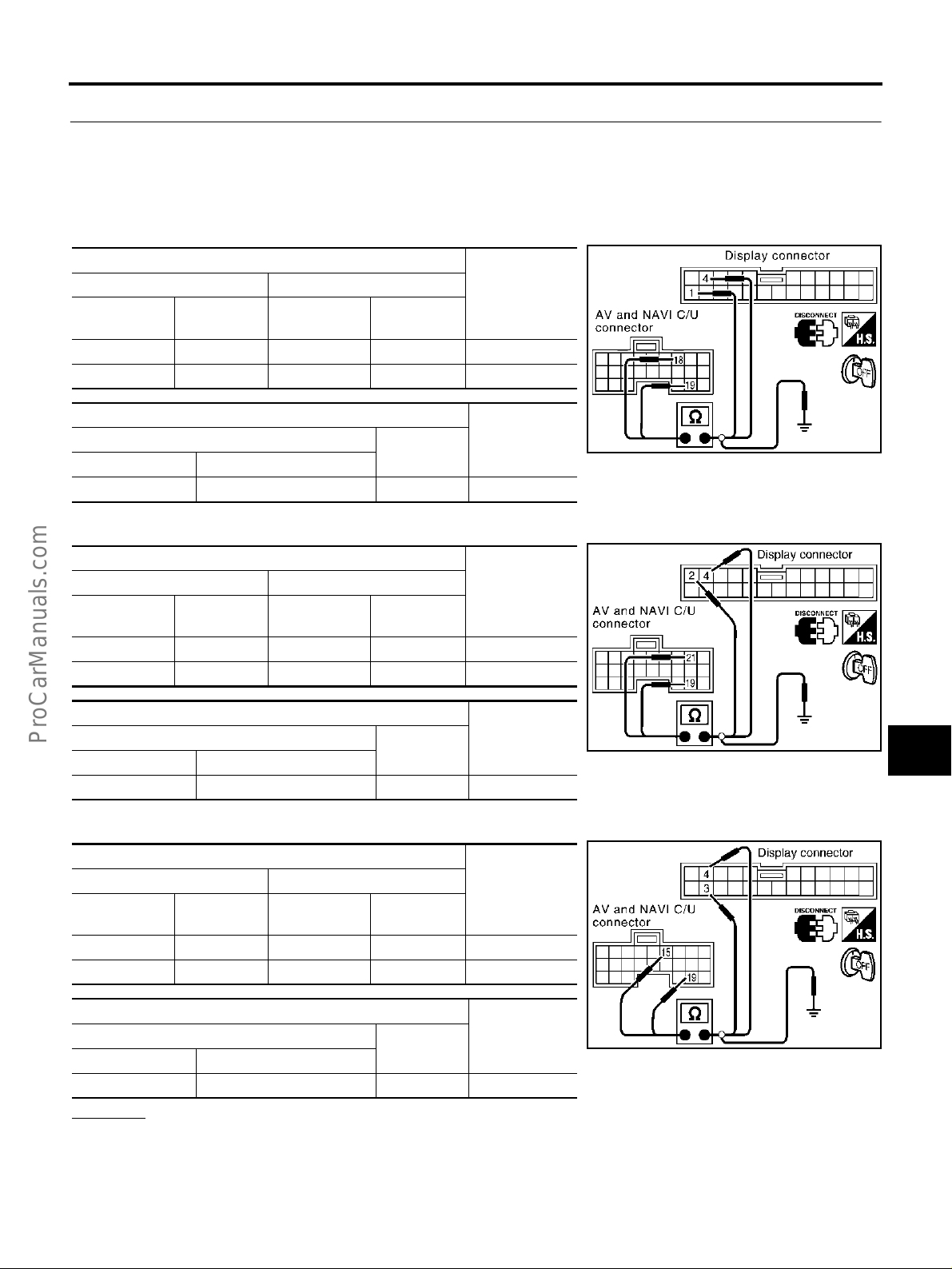
NAVIGATION SYSTEM
2. HARNESS CHECK
1. Turn ignition switch OFF.
2. Disconnect AV and NAVI control unit connector and Display connector.
3. Check continuity between AV and NAVI control unit and Display.
4. Check continuity between AV and NAVI control unit and ground.
● When the screen looks bluish
Terminals
AV and NAVI control unit (+) Display (–)
Connector
B30 18 (L) M82 1 (L) YES
B30 19 M82 4 YES
Connector Terminal (Wire color)
B30 18 (L),19 Ground N O
● When the screen looks reddi sh
AV and NAVI control unit (+) Display (–)
Connector
B30 21 (PU) M82 2 (Y) YES
B30 19 M82 4 YES
Terminal
(Wire color)
Terminals
Terminals
Terminal
(Wire color)
Terminals
Connector
Connector
Connector Terminal (Wire color)
B30 19, 21 (PU) Ground NO
Terminal
(Wire color)
(–)
Terminal
(Wire color)
(–)
Continuity
ContinuityAV and NAVI control unit(+)
Continuity
ContinuityAV and NAVI control unit(+)
SKIA3521E
SKIA3522E
A
B
C
D
E
F
G
H
I
J
AV
● When the screen looks yellowish
Terminals
AV and NAVI control unit (+) Display (–)
Connector
B30 15 (LG) M82 3 (G) YES
B30 19 M82 4 YES
Connector Terminal (Wire color)
B30 19, 15 (LG) Ground NO
Terminal
(Wire color)
Terminals
Connector
Terminal
(Wire color)
(–)
Continuity
ContinuityAV and NAVI control unit(+)
SKIA3523E
OK or NG
OK >> GO TO 3.
NG >> Repair harness.
Revision; 2004 April 2003 Q45
AV-99
L
M

NAVIGATION SYSTEM
3. RGB SIGNAL CHECK
1. Connect AV and NAVI control unit connector and Display conn ector.
2. Turn ignition switch ON.
3. Display “Color bar” by “Confirmation/Adjustment Mode” mode.
4. Check the following with CONSULT-ll or oscilloscope.
● When the screen looks bluish.
Voltage signal between AV and NAVI control unit connector B30
terminal 18 (L) and 19.
18 (L) - 19 : Refer to AV-74, "
and Reference Value for AV
and NAVI Control unit" .
● When the screen looks reddish.
Voltage signal between AV and NAVI control unit connector B30
terminal 21 (PU) and 19.
21 (PU) - 19 : Refer to AV-74, "
and Reference Value for AV
and NAVI Control unit" .
● When the screen looks yel lowish.
V oltage signal between AV and NAVI control unit connector B30 terminal 15 (LG) and 19.
15 (LG) - 19 : Refer to AV-74, "
and Reference Value for AV
and NAVI Control unit" .
OK or NG
OK >> Replace Display.
NG >> Replace AV and NAVI control unit.
Terminals
SKIA3524E
Terminals
Terminals
Revision; 2004 April 2003 Q45
AV-100
 Loading...