


ENGINE CONTROL SYSTEM
B ENGINE
A
EC
SECTION EC
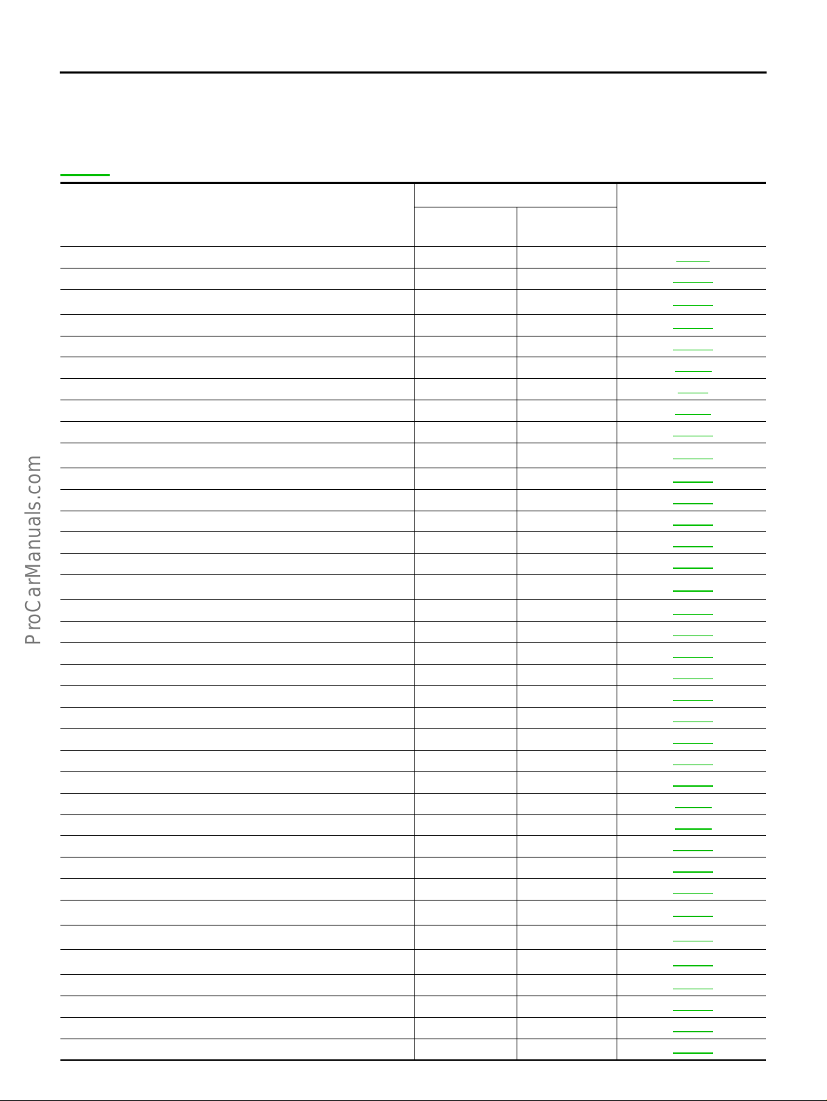
MODIFICATION NOTICE ............................................ 9
Modification Notice ................................................... 9
How to Check Vehicle Type ..................................... 9
INDEX FOR DTC ...................................................... 10
Alphabetical Index .................................................. 10
DTC No. Index ....................................................... 13
PRECAUTIONS ........................................................ 17
Precautions for Supplemental Rest raint System
(SRS) “AIR BAG” and “SEAT BELT PRE-TEN-
SIONER” ................................................................ 17
On Board Diagnostic (OBD) System of Engine and
A/T ............................ ............. ............. ............. ....... 17
Precaution ...................... ........................................ 17
Wiring Diagrams and Trouble Diagnosis ................ 20
PREPARATION ......................................................... 21
Special Service Tools ............................................. 21
Commercial Service Tools ...................................... 21
ENGINE CONTROL SYSTEM .................................. 23
System Diagram ..................................................... 23
Vacuum Hose Drawing ........................................... 24
System Chart ......................................................... 25
Multiport Fuel Injection (MFI) System .................... 26
Electronic Ignition (EI) System ............................... 28
Nissan Torque Demand (NTD) Control System ..... 29
Air Conditioning Cut Control ................................... 30
Fuel Cut Control (At No Load and High Engine
Speed) ...................... ............. ............. ............. ....... 30
CAN Communication .............................................. 30
BASIC SERVICE PROCEDURE .............................. 34
Idle Speed and Ignition Timing Check .................... 34
Idle Speed/Ignition Timing/Idle Mixture Ratio
Adjustment ............................................................. 35
Throttle Valve Closed Position Learning ................ 45
Idle Air Volume Learning ........................................ 45
Fuel Pressure Check .............................................. 48
ON BOARD DIAGNOSTIC (OBD) SYSTEM ............ 50
Introduction ............................................................ 50
Two Trip Detection Logic ........................................ 50
Emission-related Diagnostic Information ................ 51
IVIS (Inf initi V e hicle Im mobilizer System — NA TS) ... 65
ENGINE CONTROL SYSTEM
CONTENTS
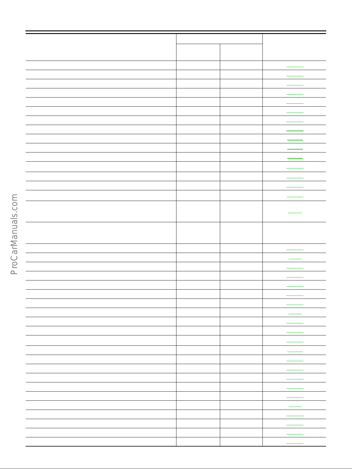
Malfunction Indicator Lamp (MIL) ...........................65
OBD System Operation Chart ................................69
TROUBLE DIAGNOSIS ............................................74
Trouble Diagnosis Introduction ...............................74
DTC Inspection Priority Chart .................................78
Fail-safe Chart ....................................... ...... ....... ....80
Basic Inspection .....................................................82
Symptom Matrix Chart ............................................86
Engine Control Component Parts Location ..........102
Circuit Diagram .....................................................107
ECM Harness Connector Terminal Layout ...........109
ECM Terminals and Reference Value ...................109
CONSULT-II Function .. ...... ....... ...... ....... ...... ....... ..118
Generic Scan Tool (GST) Function .......................130
CONSULT-II Reference Value in Data Monitor Mode
Major Sensor Reference Graph in Data Monitor
Mode .....................................................................135
TROUBLE DIAGNOSIS - SPECIFICA TION V ALUE .138
Description ................... ...... ....... ...... ......................138
Testing Condition ..................................................138
Inspection Procedure ............................................138
Diagnostic Procedure ...........................................139
TROUBLE DIAGNOSIS FOR INTERMITTENT INCI-
DENT .............................. .........................................142
Description ................... ...... ....... ...... ......................142
Diagnostic Procedure ...........................................142
POWER SUPPLY CIRCUIT FOR ECM ...................143
Wiring Diagram .....................................................143
Diagnostic Procedure ...........................................146
Component Inspection ..........................................150
DTC U1000 CAN COMMUNICATION LINE ............151
Description ................... ...... ....... ...... ......................151
On Board Diagnosis Logic ....................................151
Possible Cause .....................................................151
DTC Confirmation Procedure ...............................151
Wiring Diagram .....................................................152
Diagnostic Procedure ...........................................153
DTC P0100 MASS AIR FLOW (MAF) SENSOR ....154
Component Description ........................................154
C
D
E
F
G
H
I
J
.133
K
L
M
Revision: 2004 April 2002 Q45
EC-1

CONSULT-II Reference Value in Data Monitor Mode
On Board Diagnosis Logic ....................................154
Possible Cause .....................................................154
DTC Confirmation Procedure ...... ....... ...... ....... .....155
Overall Function Check ........................................157
Wiring Diagram .....................................................158
Diagnostic Procedure ...........................................159
Component Inspection ..........................................162
Removal and Installation ......................................162
DTC P0105 ABSOLUTE PRESSURE SENSOR ....163
Component Description ........................................163
On Board Diagnosis Logic ....................................163
Possible Cause .....................................................163
DTC Confirmation Procedure ...... ....... ...... ....... .....163
Wiring Diagram .....................................................164
Diagnostic Procedure ...........................................165
Component Inspection ..........................................167
Removal and Installation ......................................167
DTC P0110 INTAKE AIR TEMPERATURE (IAT)
SENSOR ............................ ....... ...............................168
Component Description ........................................168
On Board Diagnosis Logic ....................................168
Possible Cause .....................................................168
DTC Confirmation Procedure ...... ....... ...... ....... .....168
Wiring Diagram .....................................................170
Diagnostic Procedure ...........................................171
Component Inspection ..........................................172
Removal and Installation ......................................172
DTC P0115 ENGINE COOLANT TEMPERATURE
(ECT) SENSOR (CIRCUIT) .....................................173
Component Description ........................................173
On Board Diagnosis Logic ....................................173
Possible Cause .....................................................173
DTC Confirmation Procedure ...... ....... ...... ....... .....174
Wiring Diagram .....................................................175
Diagnostic Procedure ...........................................176
Component Inspection ..........................................177
Removal and Installation ......................................177
DTC P0120 THROTTLE POSITION (TP) SENSOR .178
Component Description ........................................178
CONSULT-II Reference Value in Data Monitor Mode
On Board Diagnosis Logic ....................................178
Possible Cause .....................................................179
DTC Confirmation Procedure ...... ....... ...... ....... .....179
Wiring Diagram .....................................................181
Diagnostic Procedure ...........................................182
Component Inspection ..........................................185
Remove and Installation ........ ...... ....... ..................185
DTC P0121 ACCELERATOR PEDAL POSITION
(APP) SENSOR .......................................................186
Component Description ........................................186
CONSULT-II Reference Value in Data Monitor Mode
On Board Diagnosis Logic ....................................186
Possible Cause .....................................................186
DTC Confirmation Procedure ...... ....... ...... ....... .....187
Wiring Diagram .....................................................188
.154
.178
.186
Diagnostic Procedure ............................................189
Component Inspection ..........................................192
Remove and Installation .......................................192
DTC P0125 ENGINE COOLANT TEMPERATURE
(ECT) SENSOR .......................................................193
Component Description ........................................193
On Board Diagnosis Logic ....................................193
Possible Cause .....................................................193
DTC Confirmation Procedure ................................193
Wiring Diagram ...................................... ...... ....... ..195
Diagnostic Procedure ............................................196
Component Inspection ..........................................196
Removal and Installation .......................................196
DTC P0130 (BANK 1), P0150 (BANK 2) HO2S1 (CIR-
CUIT) .......................................................................197
Component Description ........................................197
CONSULT-II Reference Value in Data Monitor Mode
.197
On Board Diagnosis Logic ....................................197
Possible Cause .....................................................198
DTC Confirmation Procedure ................................198
Overall Function Check .........................................199
Wiring Diagram ...................................... ...... ....... ..200
Diagnostic Procedure ............................................203
Component Inspection ..........................................204
Removal and Installation .......................................206
DTC P0131 (BANK 1), P0151 (BANK 2) HO2S1
(LEAN SHIFT MONITORING) .................................207
Component Description ........................................207
CONSULT-II Reference Value in Data Monitor Mode
.207
On Board Diagnosis Logic ....................................207
Possible Cause .....................................................207
DTC Confirmation Procedure ................................208
Overall Function Check .........................................209
Diagnostic Procedure ............................................209
Component Inspection ..........................................211
Removal and Installation .......................................212
DTC P0132 (BANK 1), P0152 (BANK 2) HO2S1
(RICH SHIFT MONITORING) ..................................213
Component Description ........................................213
CONSULT-II Reference Value in Data Monitor Mode
.213
On Board Diagnosis Logic ....................................213
Possible Cause .....................................................213
DTC Confirmation Procedure ................................214
Overall Function Check .........................................215
Diagnostic Procedure ............................................215
Component Inspection ..........................................217
Removal and Installation .......................................219
DTC P0133 (BANK 1), P0153 (BANK 2) HO2S1
(RESPONSE MONITORING) ..................................220
Component Description ........................................220
CONSULT-II Reference Value in Data Monitor Mode
.220
On Board Diagnosis Logic ....................................220
Possible Cause .....................................................220
DTC Confirmation Procedure ................................221
Overall Function Check .........................................222
Revision: 2004 April 2002 Q45
EC-2

Wiring Diagram .................................................... 223
Diagnostic Procedure ........................................... 226
Component Inspection ......................................... 230
Removal and Installation ...................................... 231
DTC P0134 (BANK 1), P0154 (BANK 2) HO2S1
(HIGH VOLTAGE) ................................................... 232
Component Description ........................................ 232
CONSULT-II Reference Value in Data Monitor Mode
On Board Diagnosis Logic ................................... 232
Possible Cause .................................................... 232
DTC Confirmation Procedure ............................... 233
Wiring Diagram .................................................... 234
Diagnostic Procedure ........................................... 237
Component Inspection ......................................... 239
Removal and Installation ...................................... 240
DTC P0135 (BANK 1), P0155 (BANK 2) HO2S1
HEATER .................................................................. 241
Description ........................................................... 241
CONSULT-II Reference Value in Data Monitor Mode
On Board Diagnosis Logic ................................... 241
Possible Cause .................................................... 241
DTC Confirmation Procedure ............................... 241
Wiring Diagram .................................................... 243
Diagnostic Procedure ........................................... 246
Component Inspection ......................................... 247
Removal and Installation ...................................... 248
DTC P0137 (BANK 1), P0157 (BANK 2) HO2S2
(MIN. VOLTAGE MONITORING) ............................ 249
Component Description ........................................ 249
CONSULT-II Reference Value in Data Monitor Mode
On Board Diagnosis Logic ................................... 249
Possible Cause .................................................... 249
DTC Confirmation Procedure ............................... 249
Overall Function Check ........................................ 250
Wiring Diagram .................................................... 251
Diagnostic Procedure ........................................... 254
Component Inspection ......................................... 258
Removal and Installation ...................................... 259
DTC P0138 (BANK 1), P0158 (BANK 2) HO2S2
(MAX. VOLTAGE MONITORING) ........................... 260
Component Description ........................................ 260
CONSULT-II Reference Value in Data Monitor Mode
On Board Diagnosis Logic ................................... 260
Possible Cause .................................................... 260
DTC Confirmation Procedure ............................... 260
Overall Function Check ........................................ 261
Wiring Diagram .................................................... 262
Diagnostic Procedure ........................................... 265
Component Inspection ......................................... 269
Removal and Installation ...................................... 270
DTC P0139 (BANK 1), P0159 (BANK 2) HO2S2
(RESPONSE MONITORING) .................................. 271
Component Description ........................................ 271
CONSULT-II Reference Value in Data Monitor Mode
. 232
. 241
. 249
. 260
. 271
On Board Diagnosis Logic ....................................271
Possible Cause .....................................................271
DTC Confirmation Procedure ...............................271
Overall Function Check ........................................272
Wiring Diagram .....................................................273
Diagnostic Procedure ...........................................276
Component Inspection ..........................................280
Removal and Installation ......................................281
DTC P0140 (BANK 1), P0160 (BANK 2) HO2S2
(HIGH VOLTAGE) ...................................................282
Component Description ........................................282
CONSULT-II Reference Value in Data Monitor Mode
.282
On Board Diagnosis Logic ....................................282
Possible Cause .....................................................282
DTC Confirmation Procedure ...............................282
Overall Function Check ........................................283
Wiring Diagram .....................................................284
Diagnostic Procedure ...........................................287
Component Inspection ..........................................291
Removal and Installation ......................................292
DTC P0141 (BANK 1), P0161 (BANK 2) HO2S2
HEATER ..................................................................293
Description ................... ...... ....... ...... ......................293
CONSULT-II Reference Value in Data Monitor Mode
.293
On Board Diagnosis Logic ....................................293
Possible Cause .....................................................293
DTC Confirmation Procedure ...............................293
Wiring Diagram .....................................................295
Diagnostic Procedure ...........................................298
Component Inspection ..........................................300
Removal and Installation ......................................300
DTC P0171 (BANK 1), P0174 (BANK 2) FUEL
INJECTION SYSTEM FUNCTION (LEAN) .............301
On Board Diagnosis Logic ....................................301
Possible Cause .....................................................301
DTC Confirmation Procedure ...............................301
Wiring Diagram .....................................................303
Diagnostic Procedure ...........................................305
DTC P0172 (BANK 1), P0175 (BANK 2) FUEL
INJECTION SYSTEM FUNCTION (RICH) ..............309
On Board Diagnosis Logic ....................................309
Possible Cause .....................................................309
DTC Confirmation Procedure ...............................309
Wiring Diagram .....................................................311
Diagnostic Procedure ...........................................313
DTC P0180 FUEL TANK TEMPERATURE (FTT)
SENSOR .................................................................316
Component Description ........................................316
On Board Diagnosis Logic ....................................316
Possible Cause .....................................................316
DTC Confirmation Procedure ...............................316
Wiring Diagram .....................................................318
Diagnostic Procedure ...........................................319
Component Inspection ..........................................320
Removal and Installation ......................................320
DTC P0300 - P0308 NO. 8 - 1 CYLINDER MISFIRE,
MUL TIPLE CYLINDER MISFIRE ............................321
A
EC
C
D
E
F
G
H
I
J
K
L
M
Revision: 2004 April 2002 Q45
EC-3

On Board Diagnosis Logic ....................................321
Possible Cause .....................................................321
DTC Confirmation Procedure ...... ....... ...... ....... .....321
Diagnostic Procedure ...........................................322
DTC P0325 (BANK 1), P0330 (BANK 2) KNOCK
SENSOR (KS) .........................................................327
Component Description ........................................327
On Board Diagnosis Logic ....................................327
Possible Cause .....................................................327
DTC Confirmation Procedure ...... ....... ...... ....... .....327
Wiring Diagram .....................................................328
Diagnostic Procedure ...........................................329
Component Inspection ..........................................330
Removal and Installation ......................................330
DTC P0335 CRANKSHAFT POSITION (CKP) SEN-
SOR (POS) ..............................................................331
Component Description ........................................331
CONSULT-II Reference Value in Data Monitor Mode
On Board Diagnosis Logic ....................................331
Possible Cause .....................................................331
DTC Confirmation Procedure ...... ....... ...... ....... .....331
Wiring Diagram .....................................................333
Diagnostic Procedure ...........................................336
Component Inspection ..........................................339
Removal and Installation ......................................339
DTC P0340 CAMSHAFT POSITION (CMP) SEN-
SOR (PHASE) .........................................................340
Component Description ........................................340
On Board Diagnosis Logic ....................................340
Possible Cause .....................................................340
DTC Confirmation Procedure ...... ....... ...... ....... .....340
Wiring Diagram .....................................................341
Diagnostic Procedure ...........................................342
Component Inspection ..........................................344
Removal and Installation ......................................345
DTC P0420 (BANK 1), P0430 (BANK 2) THREE WAY
CATALYST FUNCTION ...........................................346
On Board Diagnosis Logic ....................................346
Possible Cause .....................................................346
DTC Confirmation Procedure ...... ....... ...... ....... .....346
Overall Function Check ........................................347
Diagnostic Procedure ...........................................348
DTC P0440 EVAP CONTROL SYSTEM (SMALL
LEAK) (NEGATIVE PRESSURE) ...........................350
On Board Diagnosis Logic ....................................350
Possible Cause .....................................................350
DTC Confirmation Procedure ...... ....... ...... ....... .....351
Diagnostic Procedure ...........................................352
Component Inspection ..........................................359
DTC P0443 EVAP CANISTER PURGE VOLUME
CONTROL SOLENOID VALVE (CIRCUIT) .............360
Description ................ .......................... ..................360
CONSULT-II Reference Value in Data Monitor Mode
On Board Diagnosis Logic ....................................360
Possible Cause .....................................................360
DTC Confirmation Procedure ...... ....... ...... ....... .....361
Wiring Diagram .....................................................362
.331
.360
Diagnostic Procedure ............................................363
Component Inspection ..........................................365
Removal and Installation .......................................365
DTC P0446 EVAP CANISTER VENT CONTROL
VALVE (CIRCUIT) ....................................................366
Component Description ........................................366
CONSULT-II Reference Value in Data Monitor Mode
.366
On Board Diagnosis Logic ....................................366
Possible Cause .....................................................366
DTC Confirmation Procedure ................................366
Wiring Diagram ...................................... ...... ....... ..368
Diagnostic Procedure ............................................369
Component Inspection ..........................................371
DTC P0450 EVAP CONTROL SYSTEM PRESSURE
SENSOR ............................... ...................................373
Component Description ........................................373
CONSULT-II Reference Value in Data Monitor Mode
.373
On Board Diagnosis Logic ....................................373
Possible Cause .....................................................373
DTC Confirmation Procedure ................................374
Wiring Diagram ...................................... ...... ....... ..375
Diagnostic Procedure ............................................376
Component Inspection ..........................................380
DTC P0455 EVAP CONTROL SYSTEM (GROSS
LEAK) ......................................................................381
On Board Diagnosis Logic ....................................381
Possible Cause .....................................................381
DTC Confirmation Procedure ................................381
Diagnostic Procedure ............................................383
DTC P0460 FUEL LEVEL SENSOR FUNCTION
(SLOSH) ..................................................................389
Component Description ........................................389
On Board Diagnosis Logic ....................................389
Possible Cause .....................................................389
DTC Confirmation Procedure ................................389
Wiring Diagram ...................................... ...... ....... ..390
Diagnostic Procedure ............................................391
Remove and Installation .......................................393
DTC P0461 FUEL LEVEL SENSOR FUNCTION ...394
Component Description ........................................394
On Board Diagnosis Logic ....................................394
Possible Cause .....................................................394
Overall Function Check .........................................394
DTC P0464 FUEL LEVEL SENSOR CIRCUIT .......396
Component Description ........................................396
On Board Diagnosis Logic ....................................396
Possible Cause .....................................................396
DTC Confirmation Procedure ................................396
Wiring Diagram ...................................... ...... ....... ..397
Diagnostic Procedure ............................................398
Removal and Installation .......................................399
DTC P0500 VEHICLE SPEED SENSOR (VSS) ......400
Description ............................................................400
On Board Diagnosis Logic ....................................400
Possible Cause .....................................................400
DTC Confirmation Procedure ................................400
Revision: 2004 April 2002 Q45
EC-4

Overall Function Check ........................................ 401
Diagnostic Procedure ........................................... 401
DTC P0505 IDLE SPEED CONTROL (ISC) SYSTEM . 402
Description ........................................................... 402
On Board Diagnosis Logic ................................... 402
Possible Cause .................................................... 402
DTC Confirmation Procedure ............................... 402
Diagnostic Procedure ........................................... 403
DTC P0550 POWER STEERING PRESSURE (PSP)
SENSOR ................................................................. 404
Component Description ........................................ 404
CONSULT-II Reference Value in Data Monitor Mode
On Board Diagnosis Logic ................................... 404
Possible Cause .................................................... 404
DTC Confirmation Procedure ............................... 404
Wiring Diagram .................................................... 405
Diagnostic Procedure ........................................... 406
Component Inspection ......................................... 408
DTC P0605 ECM .................................................... 409
Component Description ........................................ 409
On Board Diagnosis Logic ................................... 409
Possible Cause .................................................... 409
DTC Confirmation Procedure ............................... 409
Diagnostic Procedure ............................................411
DTC P0650 MIL (CIRCUIT) .................................... 412
Component Description ........................................ 412
On Board Diagnosis Logic ................................... 412
Possible Cause .................................................... 412
DTC Confirmation Procedure ............................... 412
Wiring Diagram .................................................... 413
Diagnostic Procedure ........................................... 414
DTC P1065 ECM POWER SUPPLY (BACK UP) ... 416
Component Description ........................................ 416
On Board Diagnosis Logic ................................... 416
Possible Cause .................................................... 416
DTC Confirmation Procedure ............................... 416
Wiring Diagram .................................................... 417
Diagnostic Procedure ........................................... 418
DTC P1110 (BANK 1), P1135 (BANK 2) IVT CON-
TROL ...................................................................... 420
Description ........................................................... 420
CONSULT-II Reference Value in Data Monitor Mode
On Board Diagnosis Logic ................................... 421
Possible Cause .................................................... 421
DTC Confirmation Procedure ............................... 421
Wiring Diagram .................................................... 423
Diagnostic Procedure ........................................... 426
DTC P1111 (BANK 1), P1136 (BANK 2) IVT CON-
TROL SOLENOID VALVE (CIRCUIT) .................... 429
Component Description ........................................ 429
CONSULT-II Reference Value in Data Monitor Mode
On Board Diagnosis Logic ................................... 429
Possible Cause .................................................... 429
DTC Confirmation Procedure ............................... 429
Wiring Diagram .................................................... 430
Diagnostic Procedure ........................................... 433
. 404
. 420
. 429
Component Inspection ..........................................434
Removal and Installation ......................................434
DTC P1119 RADIATOR COOLANT TEMPERA-
TURE SENSOR (CIRCUIT) .....................................435
Component Description ........................................435
On Board Diagnosis Logic ....................................435
Possible Cause .....................................................435
DTC Confirmation Procedure ...............................435
Wiring Diagram .....................................................437
Diagnostic Procedure ...........................................438
Component Inspection ..........................................439
Removal and Installation ......................................439
DTC P1121 ELECTRIC THROTTLE CONTROL
ACTUATOR ................................. ............................440
Description ................... ...... ....... ...... ......................440
On Board Diagnosis Logic ....................................440
Possible Cause .....................................................440
DTC Confirmation Procedure ...............................441
Diagnostic Procedure ...........................................442
DTC P1122 ELECTRIC THROTTLE CONTROL
FUNCTION (CIRCUIT) ............................................443
Description ................... ...... ....... ...... ......................443
On Board Diagnosis Logic ....................................443
Possible Cause .....................................................443
DTC Confirmation Procedure ...............................443
Wiring Diagram .....................................................444
Diagnostic Procedure ...........................................445
Component Inspection ..........................................446
DTC P1123 THROTTLE CONTROL MOTOR RELA Y
(CIRCUIT) ....................... ............. ............. ............. ..447
Component Description ........................................447
CONSULT-II Reference Value in Data Monitor Mode
.447
On Board Diagnosis Logic ....................................447
Possible Cause .....................................................447
DTC Confirmation Procedure ...............................447
Wiring Diagram .....................................................448
Diagnostic Procedure ...........................................449
Component Inspection ..........................................451
DTC P1140 (BANK 1), P1145 (BANK 2) IVT CON-
TROL POSITION SENSOR (CIRCUIT) ..................452
Component Description ........................................452
CONSULT-II Reference Value in Data Monitor Mode
.452
On Board Diagnosis Logic ....................................452
Possible Cause .....................................................452
DTC Confirmation Procedure ...............................452
Wiring Diagram .....................................................453
Diagnostic Procedure ...........................................456
Component Inspection ..........................................459
Removal and Installation ......................................459
DTC P1148 (BANK 1), P1168 (BANK 2) CLOSED
LOOP CONTROL ....................................................460
On Board Diagnosis Logic ....................................460
Possible Cause .....................................................460
DTC Confirmation Procedure ...............................460
Overall Function Check ........................................461
Diagnostic Procedure ...........................................461
DTC P1211 VDC/TCS/ABS CONTROL UNIT ........462
A
EC
C
D
E
F
G
H
I
J
K
L
M
Revision: 2004 April 2002 Q45
EC-5

Description ................ .......................... ..................462
On Board Diagnosis Logic ....................................462
Possible Cause .....................................................462
DTC Confirmation Procedure ...... ....... ...... ....... .....462
Diagnostic Procedure ...........................................462
DTC P1212 VDC/TCS/ABS COMMUNICATION
LINE ................................... ....... ...... ....... ...... ....... .....463
Description ................ .......................... ..................463
On Board Diagnosis Logic ....................................463
Possible Cause .....................................................463
DTC Confirmation Procedure ...... ....... ...... ....... .....463
Diagnostic Procedure ...........................................463
DTC P1217 ENGINE OVER TEMPERATURE
(OVERHEAT) ...........................................................464
Description ................ .......................... ..................464
CONSULT-II Reference Value in Data Monitor Mode
On Board Diagnosis Logic ....................................465
Possible Cause .....................................................465
Overall Function Check ........................................465
Wiring Diagram .....................................................467
Diagnostic Procedure ...........................................468
Main 12 Causes of Overheating ...........................471
DTC P1220 FUEL PUMP CONTROL MODULE
(FPCM) ....................................................................472
Description ................ .......................... ..................472
CONSULT-II Reference Value in Data Monitor Mode
On Board Diagnosis Logic ....................................472
Possible Cause .....................................................472
DTC Confirmation Procedure ...... ....... ...... ....... .....473
Wiring Diagram .....................................................474
Diagnostic Procedure ...........................................475
Component Inspection ..........................................478
DTC P1320 IGNITION SIGNAL ..............................479
Component Description ........................................479
On Board Diagnosis Logic ....................................479
Possible Cause .....................................................479
DTC Confirmation Procedure ...... ....... ...... ....... .....479
Wiring Diagram .....................................................480
Diagnostic Procedure ...........................................485
Component Inspection ..........................................489
Removal and Installation ......................................489
DTC P1336 CRANKSHAFT POSITION (CKP) SEN-
SOR (POS) (COG) ..................................................490
Component Description ........................................490
CONSULT-II Reference Value in Data Monitor Mode
On Board Diagnosis Logic ....................................490
Possible Cause .....................................................490
DTC Confirmation Procedure ...... ....... ...... ....... .....490
Wiring Diagram .....................................................491
Diagnostic Procedure ...........................................494
Component Inspection ..........................................497
Removal and Installation ......................................497
DTC P1440 EVAP CONTROL SYSTEM (SMALL
LEAK) (POSITIVE PRESSURE) .............................498
On Board Diagnosis Logic ....................................498
Possible Cause .....................................................498
.465
.472
.490
DTC Confirmation Procedure ................................499
Diagnostic Procedure ............................................499
DTC P1444 EVAP CANISTER PURGE VOLUME
CONTROL SOLENOID VALVE ............................. ..500
Description ............................................................500
CONSULT-II Reference Value in Data Monitor Mode
.500
On Board Diagnosis Logic ....................................500
Possible Cause .....................................................500
DTC Confirmation Procedure ................................501
Wiring Diagram ...................................... ...... ....... ..503
Diagnostic Procedure ............................................504
Component Inspection ..........................................507
Removal and Installation .......................................508
DTC P1446 EVAP CANISTER VENT CONTROL
VALVE (CLOSE) ......................................................509
Component Description ........................................509
CONSULT-II Reference Value in Data Monitor Mode
.509
On Board Diagnosis Logic ....................................509
Possible Cause .....................................................509
DTC Confirmation Procedure ................................509
Wiring Diagram ...................................... ...... ....... ..511
Diagnostic Procedure ............................................512
Component Inspection ..........................................514
DTC P1447 EVAP CONTROL SYSTEM PURGE
FLOW MONITORING ..............................................516
System Description ...............................................516
On Board Diagnosis Logic ....................................516
Possible Cause .....................................................516
DTC Confirmation Procedure ................................516
Overall Function Check .........................................517
Diagnostic Procedure ............................................518
DTC P1448 EVAP CANISTER VENT CONTROL
VALVE (OPEN) ........................................................522
Component Description ........................................522
CONSULT-II Reference Value in Data Monitor Mode
.522
On Board Diagnosis Logic ....................................522
Possible Cause .....................................................522
DTC Confirmation Procedure ................................523
Overall Function Check .........................................524
Wiring Diagram ...................................... ...... ....... ..525
Diagnostic Procedure ............................................526
Component Inspection ..........................................528
DTC P1464 FUEL LEVEL SENSOR CIRCUIT
(GROUND SIGNAL) ................................................530
Component Description ........................................530
On Board Diagnosis Logic ....................................530
Possible Cause .....................................................530
DTC Confirmation Procedure ................................530
Wiring Diagram ...................................... ...... ....... ..531
Diagnostic Procedure ............................................532
Removal and Installation .......................................533
DTC P1480 COOLING FAN SPEED CONTROL
SOLENOID VALVE (CIRCUIT) ................................534
Description ............................................................534
CONSULT-II Reference Value in Data Monitor Mode
.535
Revision: 2004 April 2002 Q45
EC-6

On Board Diagnosis Logic ................................... 535
Possible Cause .................................................... 535
DTC Confirmation Procedure ............................... 535
Wiring Diagram .................................................... 537
Diagnostic Procedure ........................................... 538
Component Inspection ......................................... 539
Removal and Installation ...................................... 539
DTC P1490 VACUUM CUT V AL VE BYPASS V ALVE
(CIRCUIT) ............................................................... 540
Description ........................................................... 540
CONSULT-II Reference Value in Data Monitor Mode
On Board Diagnosis Logic ................................... 540
Possible Cause .................................................... 540
DTC Confirmation Procedure ............................... 541
Wiring Diagram .................................................... 542
Diagnostic Procedure ........................................... 543
Component Inspection ......................................... 545
DTC P1491 VACUUM CUT V AL VE BYPASS V ALVE . 546
Description ........................................................... 546
CONSULT-II Reference Value in Data Monitor Mode
On Board Diagnosis Logic ................................... 546
Possible Cause .................................................... 546
DTC Confirmation Procedure ............................... 547
Overall Function Check ........................................ 548
Wiring Diagram .................................................... 549
Diagnostic Procedure ........................................... 550
Component Inspection ......................................... 553
DTC P1605 A/T DIAGNOSIS COMMUNICATION
LINE ........................................................................ 554
Description ........................................................... 554
On Board Diagnosis Logic ................................... 554
Possible Cause .................................................... 554
DTC Confirmation Procedure ............................... 554
Diagnostic Procedure ........................................... 554
DTC P1706 PARK/NEUTRAL POSITION (PNP)
SWITCH .................................................................. 555
Component Description ........................................ 555
CONSULT-II Reference Value in Data Monitor Mode
On Board Diagnosis Logic ................................... 555
Possible Cause .................................................... 555
DTC Confirmation Procedure ............................... 555
Overall Function Check ........................................ 556
Wiring Diagram .................................................... 557
Diagnostic Procedure ........................................... 558
DTC P1720 VEHICLE SPEED SENSOR (A/T OUT-
PUT) ............................ ............................................ 561
Description ........................................................... 561
CONSULT-II Reference Value in Data Monitor Mode
On Board Diagnosis Logic ................................... 561
Possible Cause .................................................... 561
DTC Confirmation Procedure ............................... 561
Diagnostic Procedure ........................................... 561
DTC P1780 SHIFT CHANGE SIGNAL ................... 563
Description ........................................................... 563
On Board Diagnosis Logic ................................... 563
. 540
. 546
. 555
. 561
Possible Cause .....................................................563
DTC Confirmation Procedure ...............................563
Diagnostic Procedure ...........................................563
DTC P1805 BRAKE SWITCH .................. ...... ....... ..565
Description ................... ...... ....... ...... ......................565
CONSULT-II Reference Value in Data Monitor Mode
.565
On Board Diagnosis Logic ....................................565
Possible Cause .....................................................565
DTC Confirmation Procedure ...............................565
Wiring Diagram .....................................................566
Diagnostic Procedure ...........................................567
Component Inspection ..........................................569
VARIABLE INDUCTION AIR CONTROL SYSTEM
(VIAS) ...................... .............................................. ..570
Description ................... ...... ....... ...... ......................570
CONSULT-II Reference Value in Data Monitor Mode
.571
Wiring Diagram .....................................................572
Diagnostic Procedure ...........................................574
Component Inspection ..........................................577
Removal and Installation ......................................578
INJECTOR CIRCUIT ...............................................579
Component Description ........................................579
CONSULT-II Reference Value in Data Monitor Mode
.579
Wiring Diagram .....................................................580
Diagnostic Procedure ...........................................583
Component Inspection ..........................................586
Removal and Installation ......................................587
START SIGNAL ......................................................588
CONSULT-II Reference Value in Data Monitor Mode
.588
Wiring Diagram .....................................................589
Diagnostic Procedure ...........................................590
FUEL PUMP CIRCUIT ............................................592
Description ................... ...... ....... ...... ......................592
CONSULT-II Reference Value in Data Monitor Mode
.592
Wiring Diagram .....................................................593
Diagnostic Procedure ...........................................594
Component Inspection ..........................................597
Removal and Installation ......................................597
REFRIGERANT PRESSURE SENSOR ..................598
Component Description ........................................598
Wiring Diagram .....................................................599
Diagnostic Procedure ...........................................600
Removal and Installation ......................................602
ELECTRICAL LOAD SIGNAL ................................603
Description ................... ...... ....... ...... ......................603
Diagnostic Procedure ...........................................603
DATA LINK CONNECTOR ......................................605
Wiring Diagram .....................................................605
EVAPORATIVE EMISSION SYSTEM .....................606
Description ................... ...... ....... ...... ......................606
Component Inspection ..........................................609
How to Detect Fuel Vapor Leakage ......................610
ON BOARD REFUELING VAPOR RECOVERY
(ORVR) ................................. ...................................612
A
EC
C
D
E
F
G
H
I
J
K
L
M
Revision: 2004 April 2002 Q45
EC-7

System Description ...............................................612
Diagnostic Procedure ...........................................613
Component Inspection ..........................................616
POSITIVE CRANKCASE VENTILATION ...............619
Description ................ .......................... ..................619
Component Inspection ..........................................619
SERVICE DATA AND SPECIFICATIONS (SDS) ....621
Fuel Pressure Regulator .......................................621
Idle Speed and Ignition Timing .............................621
Calculated Load Value ..........................................621
Mass Air Flow Sensor ...........................................621
Intake Air Temperature Sensor .............................621
Engine Coolant Temperature Sensor ....................621
Heated Oxygen Sensor 1 ......................................621
Heated Oxygen sensor 2 ......................................621
Fuel Tempera ture Sensor ............................ ....... ..621
Crankshaft Position Sensor (POS) .......................622
Camshaft Position Sensor (PHASE) .....................622
Radiator Coolant Temperature Sensor .................622
Throttle Control Motor ...........................................622
Injector ..................................................................622
Fuel Pump .................... ...... ....... ...... ....... ...... ....... ..622
Revision: 2004 April 2002 Q45
EC-8

MODIFICATION NOTICE
MODIFICATION NOTICE PFP:00000
Modification Notice EBS00HVV
2-step modifications have been adopted.
FIRST STEP
● On Board Diagnoses Logic for some DT Cs have been chang ed.
A
EC
SECOND STEP
● Control conditions for VIAS control solenoid valve have been changed.
How to Check Vehicle Type EBS00HVW
Check the Calibration ID using CONSULT-II or GST and confirm the type of the vehicle.
Vehicle Type Calibration ID
Type I (Initial products) 1AR200
Type II (First step) 1AR201
Type III (Second step) 1AR202 ~
C
D
E
F
G
H
I
J
K
L
M
Revision: 2004 April 2002 Q45
EC-9
INDEX FOR DTC
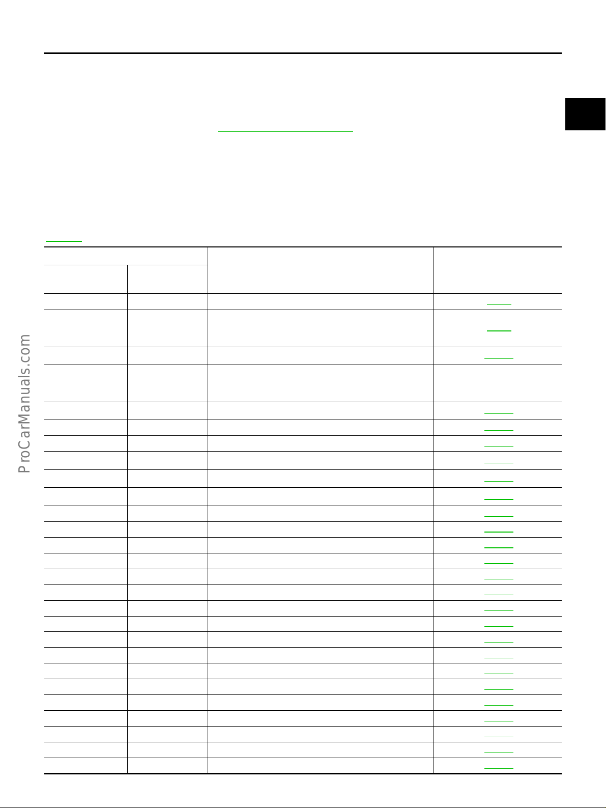
INDEX FOR DTC PFP:00024 Alphabetical Index EBS002NJ
NOTE:
If DTC U1000 is displayed with other DTC, first pe rform the trou ble diagn osis for DT C U1000. Refer to
EC-151
.
1
Items
(CONSULT-II screen terms)
Unable to access ECM — — EC-80
ABSL PRES SEN/CIRC P0105 0105 EC-163
ACCL POS SEN/CIRC*
AIR TEMP SEN/CIRC P0110 0110 EC-168
A/T DIAG COMM LINE P1605 1605 EC-554
A/T INTERLOCK P1730 1730 AT-129
A/T TCC S/V FNCTN P0744 0744 AT-97
ATF TEMP SEN/CIRC P0710 0710 AT-118
BRAKE SW/CIRCUIT P1805 1805 EC-565
CAN COMM CIRCUIT U1000
CKP SEN/CIRCUIT P0335 0335 EC-331
CKP SENSOR (COG) P1336 1336 EC-490
CLOSED LOOP-B1 P1148 1148 EC-460
CLOSED LOOP-B2 P1168 1168 EC-460
CMP SEN/CIRCUIT P0340 0340 EC-340
COOLANT T SEN/CIRC*
*COOLAN T SEN/CIRC P0125 0125 EC-193
CYL 1 MISFIRE P0301 0301 EC-321
CYL 2 MISFIRE P0302 0302 EC-321
CYL 3 MISFIRE P0303 0303 EC-321
CYL 4 MISFIRE P0304 0304 EC-321
CYL 5 MISFIRE P0305 0305 EC-321
CYL 6 MISFIRE P0306 0306 EC-321
CYL 7 MISFIRE P0307 0307 EC-321
CYL 8 MISFIRE P0308 0308 EC-321
D/C SOLENOID FNCTN P1764 1764 AT-153
D/C SOLENOID/CIRC P1762 1762 AT-150
ECM P0605 0605 EC-409
ECM BACK UP/CIRC P1065 1065 EC- 416
ENG OVER TEMP P1217 1217 EC-464
ETC ACTR*
ETC FUNCTION/CIRC*
ETC MOT RLY/CIRC*
EVAP GROSS LEAK P0455 0455 EC-381
EVAP PURG FLOW/MON P1447 1447 EC-516
EVAP SMALL LEAK P0440 0440 EC-350
EVAP SMALL LEAK P1440 1440 EC-498
7
7
5
7
7
CONSULT-II
GST*
P0121 0121 EC-186
P0115 0115 EC-173
P1121 1121 EC-462
P1122 1122 EC-443
P1123 1123 EC-447
DTC*
3
2
ECM*
1000*
6
Reference page
EC-151
Revision: 2004 April 2002 Q45
EC-10

INDEX FOR DTC
1
Items
(CONSULT-II scr een term s)
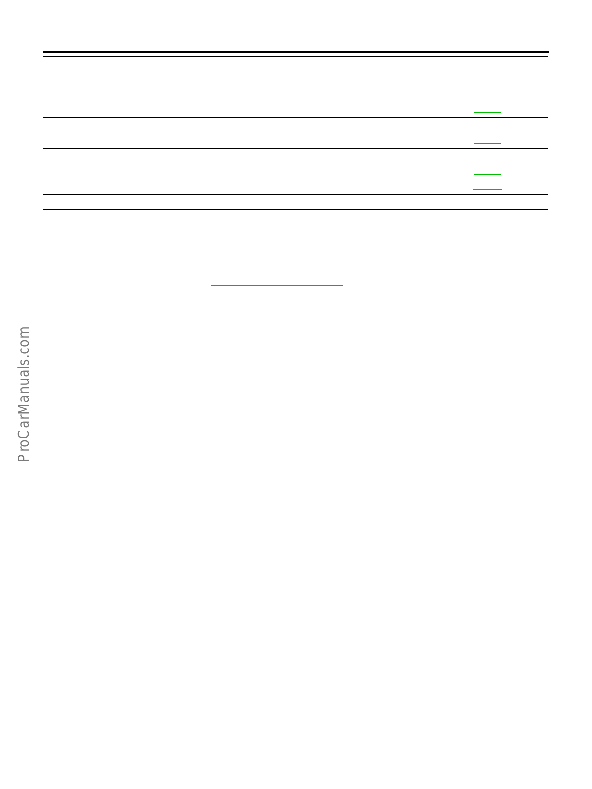
EVAP SYS PRES SEN P0450 0450 EC-373
FAN CONT S/V CIRC P1480 1480 EC-534
FPCM/CIRCUIT P1220 1220 EC-472
FR/B SOLENOID FNCT P1759 1759 AT-147
FR/B SOLENOID/CIRC P1757 1757 AT-144
FUEL LEVEL SENSOR P0461 0461 EC-394
FUEL LEVL SEN/CIRC P0464 0464 EC-396
FUEL LEVL SEN/CIRC P1464 1464 EC-530
FUEL LEV SEN SLOSH P0460 0460 EC-389
FUEL SYS-LEAN/BK1 P0171 0171 EC-301
FUEL SYS-LEAN/BK2 P0174 0174 EC-301
FUEL SYS-RICH/BK1 P0172 0172 EC-309
FUEL SYS-RICH/BK2 P0175 0175 EC-309
FUEL TEMP SEN/CIRC P0180 0180 EC-316
HLR/C SOL FNCTN P1769 1769 AT-159
HLR/C SOL/CIRC P1767 1767 AT-156
HO2S1 (B1) P0130 0130 EC-197
HO2S1 (B1) P0131 0131 EC-207
HO2S1 (B1) P0132 0132 EC-213
HO2S1 (B1) P0133 0133 EC-220
HO2S1 (B1) P0134 0134 EC-232
HO2S1 (B2) P0150 0150 EC-197
HO2S1 (B2) P0151 0151 EC-207
HO2S1 (B2) P0152 0152 EC-213
HO2S1 (B2) P0153 0153 EC-220
HO2S1 (B2) P0154 0154 EC-232
HO2S1 HTR (B1) P0135 0135 EC-241
HO2S1 HTR (B2) P0155 0155 EC-241
HO2S2 HTR (B1) P0141 0141 EC-293
HO2S2 HTR (B2) P0161 0161 EC-293
HO2S2 (B1) P0137 0137 EC-249
HO2S2 (B1) P0138 0138 EC-260
HO2S2 (B1) P0139 0139 EC-271
HO2S2 (B1) P0140 0140 EC-282
HO2S2 (B2) P0157 0157 EC-249
HO2S2 (B2) P0158 0158 EC-260
HO2S2 (B2) P0159 0159 EC-271
HO2S2 (B2) P0160 0160 EC-282
I/C SOLENOID FNCTN P1754 1754 AT-141
I/C SOLENOID/CIRC P1752 1752 AT-138
IGN SIGNAL-PRIMARY P1320 1320 EC-479
INT/V TIM CONT-B1 P1110 1110 EC-420
CONSULT-II
GST*
DTC*
3
2
ECM*
Reference pag e
A
EC
C
D
E
F
G
H
I
J
K
L
M
Revision: 2004 April 2002 Q45
EC-11
INDEX FOR DTC
1
Items
(CONSULT-II screen terms)
INT/V TIM CONT-B2 P11 35 1135 EC-420
INT/V TIM V/CIR-B1 P1 111 1111 EC-429
INT/V TIM V/CIR-B2 P1136 1136 EC-429
INTK TIM S/CIRC-B1 P1140 1140 EC-452
INTK TIM S/CIRC-B2 P1145 1145 EC-452
ISC SYSTEM/FNCTN P0505 0505 EC-402
KNOCK SEN/CIRC-B1 P0325 0325 EC-327
KNOCK SEN/CIRC-B2 P0330 0330 EC-327
L/PRESS SOL/CIRC P0745 0745 AT-101
LC/B SOLENOID FNCT P1774 1774 AT-165
LC/B SOLENOID/CIRC P1772 1772 AT-162
MAF SEN/CIRCUIT*
MIL/CIRC P0650 0650 EC-412
MULTI CYL MISFIRE P0300 0300 EC-321
NATS MALFUNCTION*
NO DTC IS DETECTED.
FURTHER TESTING
MAY BE REQUIRED.
NO DTC IS DETECTED.
FURTHER TESTING
MAY BE REQUIRED.
P-N POS SW/CIRCUIT P1706 170 6 EC-555
PNP SW/CIRC P0705 0705 AT-85
PURG VOLUME CONT/V P0443 0443 EC-360
PURG VOLUME CONT/V P1444 1444 EC-500
PW ST P SEN/CIRC P0550 0550 EC-404
RADI TEMP SEN/CIRC P1119 1119 EC-435
SHIFT SIG FNCTN P1780 1780 EC-563
TCC SOLENOID/CIRC P0740 0740 AT-94
TCS C/U FUNCTN P1211 1211 EC-462
TCS/CIRC P1212 1212 EC-463
THRTL POS SEN/CIRC*
TURBINE REV S/CIRC P1716 1716 AT-123
TW CATALYST SYS-B1 P0420 0420 EC-346
TW CATALYST SYS-B2 P0430 0430 EC-346
V/SP SEN (A/T OUT) P1720 1720 EC-561
VC CUT/V BYPASS/V P1491 1491 EC-546
VC/V BYPASS/V P1490 1490 EC-540
VEH SPD SEN/CIR AT P0720 0720 AT-89
VEH SPEED SEN/CIRC P0500 0500 EC-400
VENT CONTROL VALVE P0446 0446 EC-366
VENT CONTROL VALVE P1446 1446 EC-509
VENT CONTROL VALVE P1448 1448 EC-522
5
8
7
CONSULT-II
GST*
P0100 0100 EC-154
P1610 - P1615 1610 - 1615 BL-146
No DTC
P0000 0000 —
P0120 0120 EC-178
DTC*
3
2
ECM*
Flashing*
4
Reference page
EC-66
Revision: 2004 April 2002 Q45
EC-12
INDEX FOR DTC
*1: 1st trip DTC No. is the same as DTC No.
*2: These numbers are prescribed by SAE J2012.
*3: In Diagnostic Test Mode II (Self-diagnostic results), these numbers are controlled by NISSAN.
*4: When engine is running.
*5: When the fail-safe operation occurs, the MIL illuminates.
*6: The trouble shooting for this DTC needs CONS ULT-II.
*7: For the type II or type III vehicle (Refe r to EC-9, "
sis, the DTC will be stoned even in a 1st trip.
*8: The MIL will not be illuminated for these DTCs with type II or type III veh icle.
NOTE:
Regarding F50 models, “B1” or “BK1” indicates bank 1, “B2 ” or “BK2” i ndi cates bank 2.
How to Check Vehicle Type" .), if the ECM detect a malfunction for this self-diagno-
A
EC
C
DTC No. Index EBS002NK
NOTE:
If DTC U1000 is displayed with other DTC, first perform the trouble diagnosis for DTC U1000. Refer to
EC-151
.
1
DTC*
CONSULT-II
2
GST*
— — Unable to access ECM EC-80
No DTC
U1000
P0000 0000
P0100 0100
P0105 0105 ABSL PRES SEN/CIRC EC-163
P0110 0110 AIR TEMP SEN/CIRC EC-168
P0115 0115
P0120 0120
P0121 0121
P0125 0125 *COOLAN T SEN/CIRC EC-193
P0130 0130 HO2S1 (B1) EC-197
P0131 0131 HO2S1 (B1) EC-207
P0132 0132 HO2S1 (B1) EC-213
P0133 0133 HO2S1 (B1) EC-220
P0134 0134 HO2S1 (B1) EC-232
P0135 0135 HO2S1 HTR (B1) EC-241
P0137 0137 HO2S2 (B1) EC-249
P0138 0138 HO2S2 (B1) EC-260
P0139 0139 HO2S2 (B1) EC-271
P0140 0140 HO2S2 (B1) EC-282
P0141 0141 HO2S2 HTR (B1) EC-293
P0150 0150 HO2S1 (B2) EC-197
P0151 0151 HO2S1 (B2) EC-207
P0152 0152 HO2S1 (B2) EC-213
P0153 0153 HO2S1 (B2) EC-220
P0154 0154 HO2S1 (B2) EC-232
ECM*
Flashing*
1000*
3
NO DTC IS DETECTED.
4
FURTHER TESTING
MAY BE REQUIRED.
6
CAN COMM CIRCUIT EC-151
NO DTC IS DETECTED.
FURTHER TESTING
MAY BE REQUIRED.
MAF SEN/CIRCUIT*
COOLANT T SEN/CIRC*
THRTL POS SEN/CIRC*
ACCEL POS SEN/CIRC*
(CONSULT-II scr een term s)
Items
5
5
7
7
Reference page
EC-66
—
EC-154
EC-173
EC-178
EC-186
D
E
F
G
H
I
J
K
L
M
Revision: 2004 April 2002 Q45
EC-13

1
DTC*
CONSULT-II
2
GST*
P0155 0155 HO2S1 HTR (B2) EC-241
P0157 0157 HO2S2 (B2) EC-249
P0158 0158 HO2S2 (B2) EC-260
P0159 0159 HO2S2 (B2) EC-271
P0160 0160 HO2S2 (B2) EC-282
P0161 0161 HO2S2 HTR (B2) EC-293
P0171 0171 FUEL SYS-LEAN/BK1 EC-301
P0172 0172 FUEL SYS-RICH/BK1 EC-309
P0174 0174 FUEL SYS-LEAN/BK2 EC-301
P0175 0175 FUEL SYS-RICH/BK2 EC-309
P0180 0180 FUEL TEMP SEN/CIRC EC-316
P0300 0300 MULTI CYL MISFIRE EC-321
P0301 0301 CYL 1 MISFIRE EC-321
P0302 0302 CYL 2 MISFIRE EC-321
P0303 0303 CYL 3 MISFIRE EC-321
P0304 0304 CYL 4 MISFIRE EC-321
P0305 0305 CYL 5 MISFIRE EC-321
P0306 0306 CYL 6 MISFIRE EC-321
P0307 0307 CYL 7 MISFIRE EC-321
P0308 0308 CYL 8 MISFIRE EC-321
P0325 0325 KNOCK SEN/CIRC-B1 EC-327
P0330 0330 KNOCK SEN/CIRC-B2 EC-327
P0335 0335 CKP SEN/CIRCUIT EC-331
P0340 0340 CMP SEN/CIRCUIT EC-340
P0420 0420 TW CATALYST SYS-B1 EC-346
P0430 0430 TW CATALYST SYS-B2 EC-346
P0440 0440 EVAP SMALL LEAK EC-350
P0443 0443 PURG VOLUME CONT/V EC-360
P0446 0446 VENT CONTROL VALVE EC-366
P0450 0450 EVAP SYS PRES SEN EC-373
P0455 0455 EVAP GROSS LEAK EC-381
P0460 0460 FUEL LEV SEN SLOSH EC-389
P0461 0461 FUEL LEVEL SENSOR EC-394
P0464 0464 FUEL LEVL SEN/CIRC EC-396
P0500 0500 VEH SPEED SEN/CIRC EC-400
P0505 0505 ISC SYSTEM/FNCTN EC-402
P0550 0550 PW ST P SEN/CIRC EC- 404
P0605 0605 ECM EC-409
P0650 0650 MIL/CIRC EC-412
P0705 0705 PNP SW/CIRC AT-85
P0710 0710 ATF TEMP SEN/CIRC AT-118
P0720 0720 VEH SPD SEN/CIR AT AT-89
ECM*
INDEX FOR DTC
Items
3
(CONSULT-II screen terms)
Reference page
Revision: 2004 April 2002 Q45
EC-14

1
DTC*
CONSULT-II
P1610 - P1615 1610 - 1615
2
GST*
P0740 0740 TCC SOLENOID/CIRC AT-94
P0744 0744 A/T TCC S/V FNCTN AT-97
P0745 0745 L/PRESS SOL/CIRC AT-101
P1065 1065 ECM BACK UP/CIRC EC-416
P1110 1110 INT/V TIM CONT-B1 EC-420
P1111 1111 INT/ V TIM V/CIR- B1 EC-429
P1119 1119 RADI TEMP SEN/ CIRC EC-435
P1121 1121
P1122 1122
P1123 1123
P1135 1135 INT/V TIM CONT-B2 EC-420
P1136 1136 INT/V TIM V/CIR-B2 EC-429
P1140 1140 INTK TIM S/CIRC-B1 EC-452
P1145 1145 INTK TIM S/CIRC-B2 EC-452
P1148 1148 CLOSED LOOP-B1 EC-460
P1168 1168 CLOSED LOOP-B2 EC-460
P1211 1211 TCS C/U FUNCTN EC-462
P1212 1212 TCS/CIRC EC-463
P1217 1217 ENG OVER TEMP EC-464
P1220 1220 FPCM/CIRCUIT EC-472
P1320 1320 IGN SIGNAL-PRIMARY EC-479
P1336 1336 CKP SENSOR (COG) EC-490
P1440 1440 EVAP SMALL LEAK EC-498
P1444 1444 PURG VOLUME CONT/V EC-500
P1446 1446 VENT CONTROL VALVE EC-509
P1447 1447 EVAP PURG FLOW/MON EC-516
P1448 1448 VENT CONTROL VALVE EC-522
P1464 1464 FUEL LEVL SEN/CIRC EC-530
P1480 1480 FAN CONT S/V CIRC EC-534
P1490 1490 VC/V BYPASS/V EC-540
P1491 1491 VC CUT/V BYPASS/V EC-546
P1605 1605 A/T DIAG COMM LINE EC-554
P1706 1706 P-N POS SW/CIRCUIT EC-555
P1716 1716 TURBINE REV S/CIRC AT-123
P1720 1720 V/SP SEN (A/T OUT) EC-561
P1730 1730 A/T INTERLOCK AT-129
P1752 1752 I/C SOLENOID/CIRC AT-138
P1754 1754 I/C SOLENOID FNCTN AT-141
P1757 1757 FR/B SOLENOID/CIRC AT-144
P1759 1759 FR/B SOLENOID FNCT AT-147
P1762 1762 D/C SOLENOID/CIRC AT-150
ECM*
INDEX FOR DTC
Items
3
ETC ACTR*
ETC FUNCTION/CIRC*
ETC MOT RLY/CIRC*
NATS MALFUNCTION*
(CONSULT-II scr een term s)
7
7
7
8
Reference page
EC-440
EC-443
EC-447
BL-146
A
EC
C
D
E
F
G
H
I
J
K
L
M
Revision: 2004 April 2002 Q45
EC-15
INDEX FOR DTC
1
DTC*
CONSULT-II
*1: 1st trip DTC No. is the same as DTC No.
*2: These numbers are prescribed by SAE J2012.
*3: In Diagnostic Test Mode II (Self-diagnostic results), these numbers are controlled by NISSAN.
*4: When engine is running.
*5: When the fail-safe operation occurs, th e MIL ill um in ate s.
*6: The trouble shooting for this DTC needs CONSULT-II.
*7: For the type II or type III vehicle (Refer to EC-9, "
sis, the DTC will be stoned even in a 1st trip.
*8: The MIL will not be illuminated for these DTCs with type II or type III vehicle.
NOTE:
Regarding F50 models, “B1” or “BK1” indicates bank 1, “B2” or “BK2” indicates bank 2.
2
GST*
P1764 1764 D/C SOLENOID FNCTN AT-153
P1767 1767 HLR/C SOL/CIRC AT-156
P1769 1769 HLR/C SOL FNCTN AT-159
P1772 1772 LC/B SOLENOID/CIRC AT-162
P1774 1774 LC/B SOLENOID FNCT AT-165
P1780 1780 SHIFT SIG FNCTN EC-563
P1805 1805 BRAKE SW/CIRCUIT EC-565
ECM*
3
(CONSULT-II screen terms)
How to Check Vehicle Type" .), if the ECM detect a malfunction for this self-diagno-
Items
Reference page
Revision: 2004 April 2002 Q45
EC-16

PRECAUTIONS
PRECAUTIONS PFP:00001
Precautions for Supplemental Restraint System (SRS) “AIR BAG” and “SEAT BELT PRE-TENSIONER”
The Supplemental Rest raint System such as “AIR BAG” and “SEAT BELT PR E-TENSIONER”, used along
with a front seat belt, helps to redu ce th e risk or se verit y of i njury to the driv er and front passenge r for ce rtain
types of col lision. Information necessary to service the system safely is includ ed in the SRS a nd SB section of
this Service Manual.
WARNING:
● To avoid rendering the SRS inopera tive, whi ch could incr ease the risk of pe rsonal injury or death
in the event of a collision which would result in air bag inflation, all maintenance must be performed by an authorized NISSAN/INFINITI dealer.
● Improper maintenance, inc luding incorrect removal and installation of the SRS, can lead to per-
sonal injury ca use d by unintentional ac tiv atio n o f the s ys tem . F or re moval of Spiral C ab le and Air
Bag Module, see the SRS sec tion.
● Do not use electrical test equ ipment o n any circu it related to the SRS unless in structed to in this
Service Manual. SRS wiring harnesses can be id entified by yellow and/or orange harnesses or
harness connectors.
EBS003C6
On Board Diagnostic (OBD) System of Engine and A/T EBS000PU
A
EC
C
D
E
F
The ECM has an on boa rd diagnos tic system. It wil l light up the m alfunction indicator la mp (MIL) to warn th e
driver of a malfunction causing emission deterioration.
CAUTION:
● Be sure to turn the ignitio n switch OFF and disconne ct the negative battery term inal before any
repair or inspection work. The open/short circuit of related switches, sensors, solenoid valves,
etc. will cause the MIL to light up.
● Be sure to connect and lock the connectors securely after work. A loose (unlocked) connector will
cause the MIL to light up due to the open circuit. (Be sure the connector is free from water, grease,
dirt, bent terminals, etc.)
● Certain systems and components, especially those related to OBD, may use a new style slide-
locking type harness connector. For description and how to disconnect, refer to PG-65, "
NESS CONNECTOR" .
● Be sure to route and secure the harnesses properly after work. The interference of the harness
with a bracket, etc. may cause the MIL to light up due to the short circuit.
● Be sure to connect rubber tubes properly after work. A misconnected or disconnected rubber tube
may cause the MIL to ligh t up due to the m al func tion of the EVAP system or fuel injection system ,
etc.
● Be sure to erase the unnecessary malfunction information (repairs completed) from the ECM and
TCM (Transmission control module) before returning the vehicle to the customer.
Precaution EBS000PV
● Always use a 12 volt battery as power source.
● Do not attempt to disconne ct b attery c abl es w hile engine is
running.
● Before connecting or d isconnecting th e ECM harnes s con-
nector, turn ignition switch OFF and disconnect negative
battery terminal. Failure to do so may damage the ECM
because battery voltage is applie d to ECM even if ignition
switch is turned off.
● Before removing parts, turn ignition switch OFF and then
disconnect battery ground cable.
HAR-
SEF289H
G
H
I
J
K
L
M
Revision: 2004 April 2002 Q45
EC-17

PRECAUTIONS
● Do not disassemble ECM.
● If a battery terminal is disconnected, the memory will return
to the ECM value.
The ECM will now start to self-control at its initial value.
Engine operation can vary sl ightl y w he n the te rmin al i s di sconnected. However, this is not an indication of a problem.
Do not replace parts because of a slight var iation.
● When connecting ECM harness connector, fasten it
securely with a lever as far as it will go as shown at right.
SEF707Y
● When connecting or discon necting pin connectors into or
from ECM, take care not to damage pin terminals (bend or
break).
Make sure that there are not any bends or breaks on ECM
pin terminal, when connecting pin connectors.
● Securely connect ECM harness connectors.
A poor connection can cause an extremely high (surge)
voltage to develop in coil and condenser, thus resulting in
damage to ICs.
● Keep engi ne con tr ol ha rn es s a t le as t 10 cm (4 i n) a way f rom
adjacent harness, to prevent engine control system malfunctions due to receivin g external noise, degrad ed operation of ICs, etc.
● Keep engine control system parts and harness dry.
PBIB0088E
PBIB0089E
PBIB0090E
Revision: 2004 April 2002 Q45
EC-18

PRECAUTIONS
● Before replacing ECM, perform “ECM Terminals and Refer-
ence Value” inspection and make sure ECM functions properly. Refer to EC-109
● Handle mass air flow sensor carefully to avoid damage.
● Do not disassemb le mass air flow s ensor.
● Do not clean mass ai r flow sensor with any type of deter-
gent.
● Do not disassemble electric throttle control actuator.
● Even a slight leak in the air intake system can cause seri-
ous problems.
● Do not shock or jar the camshaft position sensor (PHASE),
crankshaft position sensor (POS).
● After performing each TROUBLE DIAGNOSIS, perform
“DTC Confirmation Procedure” or “Overall Function
Check”.
The DTC should not be dis played i n the “DTC Con firmatio n
Procedure” if the repair is completed. The “Overall Function Check” should be a good result if the repair is completed.
.
A
EC
C
MEF040D
D
E
F
G
● When measuring ECM signals with a circuit tester, never
allow the two tester probes to contact.
Accidental contact of probes will cause a short c ircuit and
damage the EC M power transistor.
● Do not use ECM ground terminals when measuring input/
output volt ag e. Doi ng so ma y resul t in dam age t o the ECM' s
transistor. Use a ground other than ECM terminals, such as
the ground.
SEF217U
H
I
J
K
L
M
SEF348N
Revision: 2004 April 2002 Q45
EC-19
PRECAUTIONS
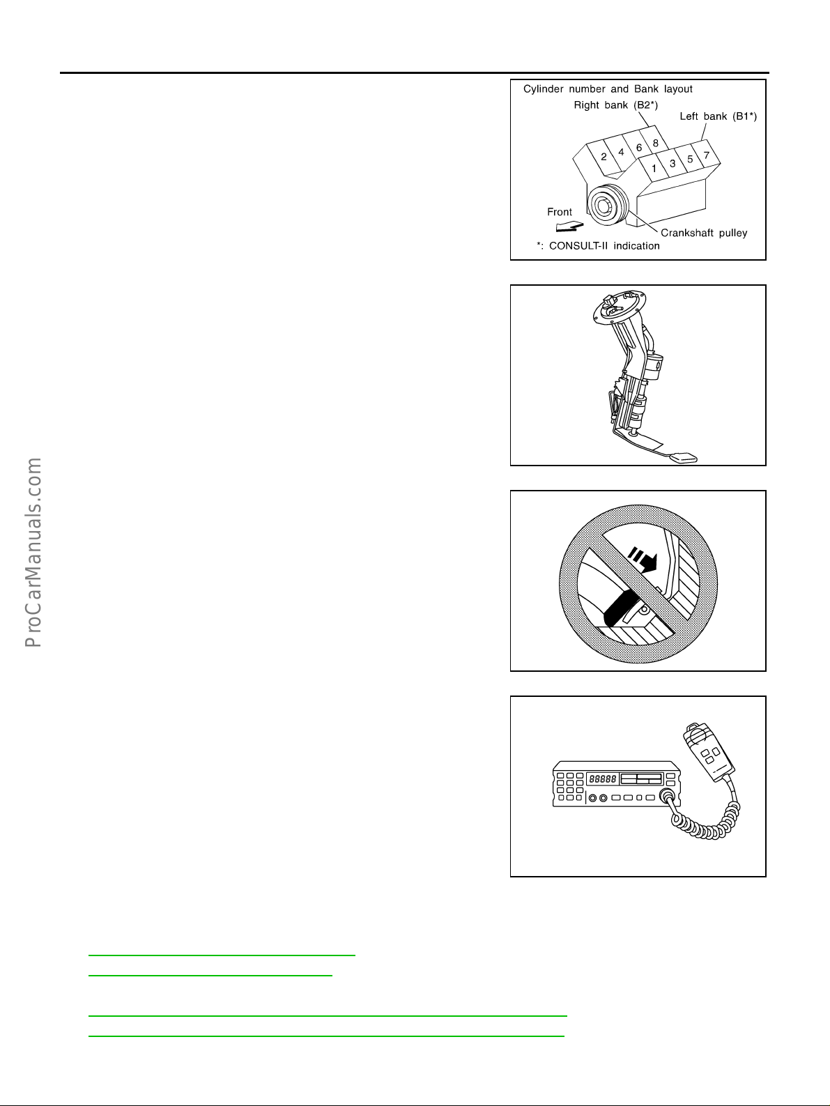
● Regarding model F50, “-B1” ind icates the bank 1 and “-B2”
indicates the bank 2 as shown in the figure.
● Do not operate fuel pump when there is no fuel in lines.
● Tighten fuel hose clamps to the specified torque.
SEF202UB
● Do not depress accelerator pedal when starting.
● Immediately after starting, do not rev up engine unneces-
sarily.
● Do not rev up engine just prior to shutdown.
● When installing C.B. ham radio or a mobile phone, be sure
to observe the following as it may adversely affect electronic control systems depending on installation location.
– Keep the antenna as far as possible from the electronic
control units.
– Keep the antenna feeder line more than 20 cm (8 in) away
from the harness of electronic controls.
Do not let them run parallel for a long distance.
– Adjust the antenna and feeder line so that the standing-
wave radio can be kept smaller.
– Be sure to ground the radio to vehicle body.
PBIB0132E
SEF709Y
SEF708Y
Wiring Diagrams and Trouble Diagnosis EBS000PW
When you read Wiring diagrams, refer to the following:
● GI-14, "How to Read Wiring Diagrams"
● PG-2, "POWER SUPPLY ROUTING" for power distributio n ci rcuit
When you perfo rm trouble diagnosis, refer to the following:
● GI-10, "HOW TO FOLLOW TEST GROUPS IN TROUBLE DIAGNOSES"
● GI-26, "How to Perform Efficient Diagnosis for an Electrical Incident"
Revision: 2004 April 2002 Q45
EC-20
PREPARATION
PREPARATION PFP:00002
Special Service Tools EBS000PX
The actual shapes of Kent-Moore tools may differ from those of spec ial ser vi ce tool s illust rat ed here.
Tool number
(Kent-Moore No.)
Tool name
Description
A
EC
KV10117100
(J36471-A)
Heated oxygen
sensor wrench
S-NT379
KV10114400
(J38365)
Heated oxygen
sensor wrench
S-NT636
Loosening or tightening heated oxygen sensors
with 22 mm (0.87 in) hexagon nut
Loosening or tightening heated oxygen sensors
a: 22 mm (0.87 in)
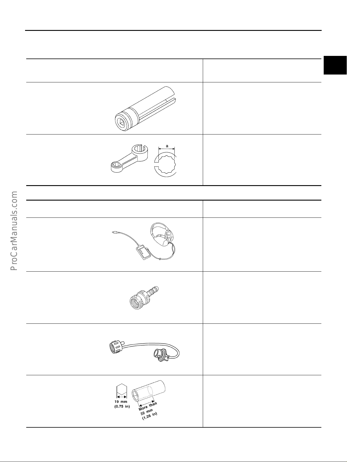
Commercial Service Tools EBS000PY
Tool name (KentMoore No.)
Leak detector
(J41416)
Description
Locating the EVAP leak
C
D
E
F
G
H
I
J
S-NT703
EVAP service port
adapter (J41413OBD)
S-NT704
Fuel filler cap adapter
(MLR-8382)
S-NT815
Socket wrench Removing and installing engine coolant
S-NT705
Applying positive pressure through EVAP service
port
Checking fuel tank vacuum relief valve opening
pressure
temperature sensor
K
L
M
Revision: 2004 April 2002 Q45
EC-21

PREPARATION
Tool name ( K entMoore No.)
Oxygen sensor thread
cleaner
(J-43897-18)
(J-43897-12)
Anti-seize lubricant
(Permatex
or equivalent meeting
MIL speci fication MILA-907)
TM
133AR
Description
Reconditioning the exhaust syst em threads
before installing a new oxygen sensor. Use with
anti-seize lubricant shown below.
a: J-43897-18 18 mm diameter, for Zirconia
Oxygen Sensor
b: J-43897-12 12 mm diameter, for Titania
Oxygen Sensor
S-NT778
Lubricating oxygen sensor thread clea ni ng to ol
when reconditioning exhaust system threads.
S-NT779
Revision: 2004 April 2002 Q45
EC-22

ENGINE CONTROL SYSTEM
ENGINE CONTROL SYSTEM PFP:23710
System Diagram EBS000Q0
A
EC
C
D
E
F
G
H
I
J
K
L
M
PBIB0006E
Revision: 2004 April 2002 Q45
EC-23

ENGINE CONTROL SYSTEM
Vacuum Hose Drawing EBS000Q1
Refer to EC-23, "System Diagram" for Vacuum Control System.
PBIB0007E
Revision: 2004 April 2002 Q45
EC-24

ENGINE CONTROL SYSTEM
System Chart EBS000Q2
Input (Sensor) ECM Function Output (Actuator)
● Camshaft position sensor (PHASE)
● Crankshaft position sensor (POS )
● Mass air flow sensor
● Engine coolant temperature sensor
● Heated oxygen sensor 1
● Throttle position sensor
● Accelerator pedal position sensor
● Park/neutral position (PNP) switch
● Intake air temperature sensor
● Absolute pressure sensor
● Power steering pressure sensor
● Ignition switch
● Battery voltage
● Knock sensor
● Refrigerant pressure sensor
● Fuel level sensor*
● EVAP control system pressure sensor *
● Fuel tank temperature sensor *
● Heated oxygen sensor 2 *
● TCM (Transmission control module) *
● VDC/TCS/ABS control unit *
● Vehicle speed *
● Air conditioner switch *
● Electrical load *
1
1
2
3
3
3
3
3
*1: These sensors are not used to control the en gin e syst em . They ar e used onl y f or t he on boa rd di agnosis.
*2: This sensor is not used to control the engine system under normal conditions.
*3: The signals are sent to the ECM through CAN communication line.
Fuel injection & mixture ratio control Fuel injectors
Electronic ignition system Power transistor
Nissan torque demand control syst em
Fuel pump control
● Electric throttle control actuator
● Fuel injectors
● Fuel pump relay
● Fuel pump control module
(FPCM)
On board diagnostic system MIL (On the instrument panel)
Power valve control VIAS control solenoid valve
Heated oxygen sensor 1 heater contr ol Heated oxygen sensor 1 heater
Heated oxygen sensor 2 heater contr ol Heated oxygen sensor 2 heater
EVAP canister purge flow control
EVAP canister purge volume control
solenoid valve
Air conditioning cut control Air conditioner relay
Cooling fan speed control
1
ON BOARD DIAGNOSIS for EVAP system
Cooling fan speed control solenoid
valve
● EVAP canister vent control valve
● Vacuum cut valve bypass valve
A
EC
C
D
E
F
G
H
I
J
K
Revision: 2004 April 2002 Q45
EC-25
L
M

ENGINE CONTROL SYSTEM
Multiport Fuel Injection (MFI) System EBS000Q3
INPUT/OUTPUT SIGNAL CHART
Sensor Input Signal to ECM
Crankshaft position sensor (POS)
Camshaft position sensor (PHASE)
Mass air flow sensor Amount of intake air
Engine coolant temperature sensor Engine coolant temperature
Heated oxygen sensor 1 Density of oxygen in exhaust gas
Throttle position sensor Throttle position
Accelerator pedal position sensor Throttle valve idle position
Park/neutral position (PNP) switch Gear position
Ignition switch Start signal
Knock sensor Engine knocking condition
Battery Battery voltage
Absolute pressure sensor Ambient air barometric pressure
Power steering pressure sensor Power steering operation
Heated oxygen sensor 2 *
VDC/TCS/ABS control unit *
Vehicle speed *
Air conditioner switch *
*1: Under normal conditions, this sensor is not for engine control operation.
*2: Signals are sent to the ECM through CAN communication line.
2
1
2
2
Engine speed
Piston position
Density of oxygen in exhaust gas
VDC/TCS operation command
Ve hicle speed
Air conditioner operation
ECM func-
tion
Fuel injection & mixture ratio
control
Actuator
Fuel injectors
SYSTEM DESCRIPTION
The amount of fuel injected from the fuel injector is determined by the ECM. The ECM controls the length of
time the valve remains open (inj ection pu lse durati on). The a mount of fuel inject ed is a pr ogram val ue in the
ECM memory. The program value is preset by engine operating conditions. These conditions are determined
by input signal s (for engine speed an d intake air) from both the cra nkshaft positio n sensor and the mas s air
flow sensor.
VARIOUS FUEL INJECTION INCREASE/DECREASE COMPENSATION
In addition, the amount of fuel injected is compensated to improve engine performance under various operating conditions as listed below.
<Fuel increase>
● During warm-up
● When starting the engine
● During acceleration
● Hot-engine operatio n
● When selector lever is chan ged from “N” to “D”
● High-load, high-speed operation
<Fuel decrease>
● During deceleration
● During high engine speed operation
Revision: 2004 April 2002 Q45
EC-26

ENGINE CONTROL SYSTEM
MIXTURE RATIO FEEDBACK CONTRO L (CLO SED LO OP CONTRO L)
A
EC
C
PBIB0121E
The mixture r atio feedback system provides the best air-fuel mixture ratio for driveability and emission control.
The three way catalyst (manifold) can then better reduce CO, HC and NOx emissions. This system uses
heated oxygen s ensor 1 in the exhau st manifold to m onitor if the engine operation is rich or lean. The ECM
adjusts the injection pulse width according to the sensor voltage signal. For more information about heated
oxygen sensor 1, r e fer to EC-197
. This maintains the mixture ratio within the range of stoichiometric (ideal airfuel mixture).
This stage is referred to as the closed loop control condition.
Heated oxygen sens or 2 is located downstream of the three way catalyst (manifold). Even if the switching
characteristics of heated oxyge n sensor 1 shift , the air-fuel ratio is controlled to stoichiometric by the signal
from heated oxygen sensor 2.
Open Loop Control
The open loop system condition refers to when the ECM detects any of the following conditions. Feedback
control stops in order to maintain stabilized fuel combustion.
● Deceleration and acceleration
● High-load, high-speed operation
● Malfunction of heated oxygen sensor 1 or its circuit
● Insufficient activation of heated oxygen sensor 1 at low engine coolant temperature
● High engine coolant temperatu re
● During warm-up
● After shifting from “N” to “D”
● When starting the engine
MIXTURE RATIO SELF-LEARNING CONTROL
The mixture ratio fe edback control syste m monitors the mixture ratio signal transmit ted from heated oxygen
sensor 1. This feedba ck sign al is then se nt to the ECM. Th e ECM contro ls the bas ic mixture ratio as close to
the theoretical mixture ratio as possible. However, the basic mixture ratio is not necessarily controlled as originally designed. Both manufacturing differences (i.e., mass air flow sensor hot film) and characteristic changes
during operation (i.e., injector clogging) directly affect mixture ratio.
Accordingly, the dif fer e nc e b etw ee n the ba si c a nd the or e tica l mi xt ure r ati os i s m on it ore d in t his sys te m. T his is
then computed in terms of “injection pu lse duration” to autom atically compens ate for the difference betw een
the two ratios.
“Fuel trim” refers to the feedback compensation valu e compared against the basic injection duration. Fuel trim
includes short term fuel trim and long term fuel trim.
“Short term fuel trim” is the sh ort-term fuel c ompensatio n used to ma intain the mixture ratio at its th eoretical
value. The signal from heated oxygen sensor 1 indicates whether the mixture ratio is RICH or LEAN compared
to the theoretica l value. Th e signal then trigge rs a reductio n in fuel volume if the mixtu re ratio is rich, and a n
increase in fuel volume if it is lean.
“Long term fuel trim” is ov erall fue l compens ation ca rried out long -term to compe nsate fo r continual deviation
of the short t e rm fue l t rim f rom t he c en tra l valu e. Su ch dev ia ti o n wil l oc cu r d ue to in di vi dual eng i ne differences,
wear over time and changes in the usage environment.
D
E
F
G
H
I
J
K
L
M
Revision: 2004 April 2002 Q45
EC-27
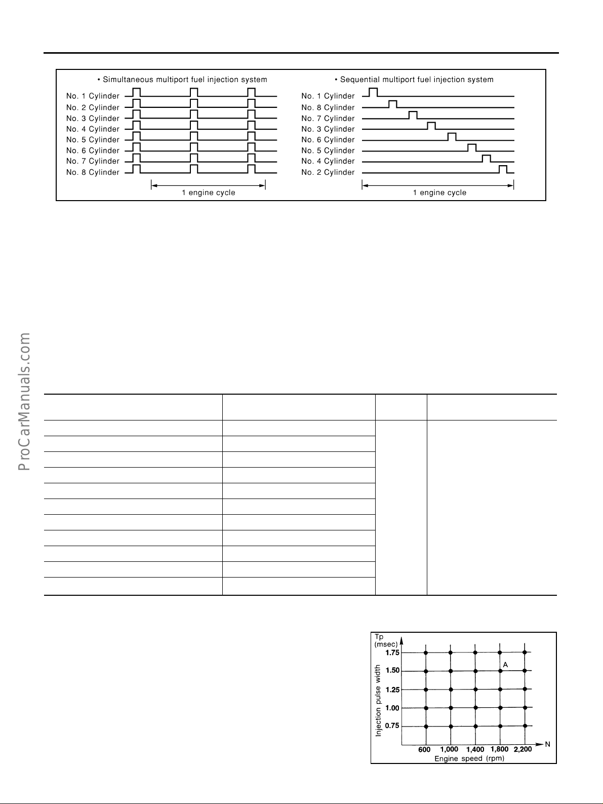
ENGINE CONTROL SYSTEM
FUEL INJECTION TIMING
PBIB0122E
Two types of systems are used.
Sequential Multiport Fuel Injection System
Fuel is injec ted into each cy linder d uring ea ch engi ne cyc le accordi ng to the firin g order. This system i s used
when the engine is running.
Simultaneous Multiport Fuel Injection System
Fuel is inject ed simul taneously into all eight cyl ind er s t wic e e ach engi ne cyc le . I n oth er wor ds, pu ls e si gnal s o f
the same width are simultaneously transmitted from the ECM.
The eight injectors will then receive the signals two times for each engine cycle.
This system is used when the engine is being started and/or if the fail-s afe system (CPU) is operating.
FUEL SHUT-OFF
Fuel to each cylinder is cut off during deceleration or operation of the engine at exc essively high speeds.
Electronic Ignition (EI) System EBS000Q4
INPUT/OUTPUT SIGNAL CHART
Sensor Input Signal to ECM
Crankshaft position sensor (POS) Engine speed
Camshaft position sensor (PHASE) Piston position
Mass air flow sensor Amount of intake air
Engine coolant temperature sensor Engine coolant temperature
Throttle position sensor Throttle position
Accelerator pedal position sensor Throttle valve idle position
Ignition switch Start signal
Knock sensor Engine knocking
Park/neutral position (PNP) switch Gear position
Battery Battery voltage
Vehicle speed *
*1: Signal is sent to the ECM through CAN communica tion lin e.
1
Ve hicle speed
SYSTEM DESCRIPTION
The ignition timing is controlled by the ECM to maintain the best airfuel ratio for every running condition of the engine. The ignition timing data is stored in the ECM. This data forms the map shown.
The ECM receives information such as the injection pulse width and
camshaft position sensor signal. Computing this information, ignition
signals are transmitted to the power transistor.
e.g., N: 1,800 rpm, Tp: 1.50 msec
A °BTDC
During the foll owing condition s, the ignition timi ng is revised by the
ECM according to the other data stored in the ECM.
● At starting
ECM func-
tion
Ignition
timing
control
Power transistor
Actuator
SEF742M
Revision: 2004 April 2002 Q45
EC-28

ENGINE CONTROL SYSTEM
● During warm-up
● At idle
● At low battery voltage
● During acceleration
The knock sensor retard system is designed only for emergencies. The basic ignition timing is programmed
within the anti-knocking zone, if recommended fuel is used under dry conditions. The retard system does not
operate under normal driving conditions. If engine knocking occurs, the knock sensor monitors the condition.
The signal is transmitted to the ECM. The ECM retards the ignition timing to eliminate the knocking condition.
Nissan Torque Demand (NTD) Control System EBS003CU
INPUT/OUTPUT SIGNAL CHART
Sensor Input signal to ECM ECM function Actuator
Camshaft position sensor (PHAS E)
Crankshaft position sensor (POS)
Mass air flow sensor Amount of intake air
Engine coolant temperature sensor Engine coolant temperature
Electric throttle control actuator
PNP switch Gear position
Power steering pressure sensor Power steer in g oper at io n
Battery Battery voltage
TCM (CAN communication) A/T control signal
A/C auto. amp. *
VDC/TCS/ABS control unit *
Combination meter *
Electric load *
*1: Signals are sent to the ECM through CAN communica tion l ine.
1
1
1
1
Engine speed
Accelerator pedal position and throttle position
Air conditioner operation
VDC/TCS/ABS operation
Vehicle speed
Electrical load signal
NTD control
Electric throttle control actuator and fuel
injector
A
EC
C
D
E
F
G
H
I
J
SYSTEM DESCRIPTION
NTD control system decides the target traction based on the accelerator operation status and the current driving condition. It then selects the engine torque target by correcting running resistance and atmospheric pressure, and controlling the power-train. Using electric throttle control actuator, it achieves the engine torque
development target which corresponds linearly to the driver's accelerator operation.
Running resistance correction control compares the engine torque estimate value, measured vehicle acceleration, and run ning resista nce on a f lat road, and estim ates vehic le weig ht gain a nd running re sistance v ariation caused by slopes to correct the engine torque estimate value.
Atmospheric pressure correction control compares the engine torque estimate value from the airflow rate and
the target engine torque for the target traction, and estimates variation of atmospheric pressure to correct the
target engine torque. This system achieves powerful driving without reducing engine performance in the practical speed range in mountains and high-altitude areas.
K
L
M
Revision: 2004 April 2002 Q45
EC-29

ENGINE CONTROL SYSTEM
Air Conditioning Cut Control EBS000Q5
INPUT/OUTPUT SIGNAL CHART
Sensor Input Signal to ECM
Air conditioner switch *
Throttle position sensor Throttle valve opening angle
Crankshaft position sensor (POS) Engine speed
Engine coolant temperature sensor Engine coolant temperature
Ignition switch Start signal
Refrigerant pressure sensor Refrigerant pressure
Power steering pressure sensor Power steering operation
Vehicle speed *
*1: Signals are sent to the ECM through CAN communication line.
1
1
Air conditioner “ON” signal
Vehicle speed
SYSTEM DESCRIPTION
This system improves engine operation when the air conditioner is used.
Under the following conditions, the air conditioner is turned off.
● When the accelerator pedal is fully depressed.
● When cranking the engine.
● At high engine speeds.
● When the engine coolant temperature becomes excessively high.
● When operating power steering during low engine speed or low vehicle speed.
● When engine speed is excessively low.
● When refrigerant pressure is excessively low or high.
ECM func-
tion
Air conditioner cut
control
Actuator
Air conditioner relay
Fuel Cut Control (At No Load and High Engine Speed) EBS000Q6
INPUT/OUTPUT SIGNAL CHART
Sensor Input Signal to ECM
Park/neutral position (PNP) switch Neutral posi tion
Throttle position sensor Throttle position
Accelerator pedal position sensor Closed throttle position
Engine coolant temperature sensor Engine coolant temperature
Crankshaft position sensor (POS) Engine speed
Vehicle speed *
*1: Signal is sent to the ECM through CAN communica tion lin e.
1
Ve hicle speed
ECM func-
tion
Fuel cut
control
Actuator
Fuel injectors
SYSTEM DESCRIPTION
If the engine speed is above 1,4 00 rpm with no load (f or example, in neut ral and engine spee d over 1,400
rpm) fuel will be cut off after some time. The exact time when the fuel is cut off varies based on engine speed.
Fuel cut will operate until the engine speed reaches 1,000 rpm, then fuel cut is cancelled.
NOTE:
This function is different from deceleration control listed under “Multiport Fuel Injection (MFI) System”, EC-26
CAN Communication EBS003GJ
SYSTEM DESCRIPTION
CAN (Controller Area N et w ork ) is a s eri al co mm u nic a tio n l ine for real time appl ic ati on . It is an on-vehicl e m ul tiplex communi catio n lin e wit h high da t a comm unic ation speed and ex cellen t er ror det ecti on ab ilit y. Many electronic control u nits are eq uipped o nto a ve hicle, a nd eac h control unit sh ares info rmation and link s with ot her
control units duri ng operation (not independent). In CAN communicatio n, control units ar e connected wi th 2
communication lines (CAN H line, CAN L line) allowing a high rate of information transmission with less wiring.
Each control unit transmits/receives data but selectively reads required data only.
.
Revision: 2004 April 2002 Q45
EC-30

FOR VDC MODELS
System Diagram
ENGINE CONTROL SYSTEM
A
EC
C
D
PBIB0124E
Input/output Signal Chart
T: Transmit R: Receive
Signals TCM
Engine speed signal R R R T
Engine coolant temperature signal R R T
Accelerator pedal position signal R R T
Engine torque signal R R T
Battery voltage signal R T
Closed throttle position signal R T
Wide open throttle position signal R T
Lock-up prohibition signal R T
Torque -do w n perm ission signal R T
Fuel consumption monitor signal R T
Lock-up signal T R
Hard deceleration signal T R
Torque -do w n sig nal T R
Power mode indicator signal T R
A/T fluid temperature warning lamp signal T R R
Current gear position signal
Next gear position signal T R R
Shift change signal T R R
Shift pattern signal T R
VDC system control signal TR
VDC operation signal TR
Stop lamp switch signal R T
Steering wheel angle sensor signal R T R R
Air conditioner switch signal T R
Headlamp switch signal T R
Rear window defogger switch signal T R
OD canncel switch signal R T R
Brake switch signal R T
Power mode switch signal R T
TR RR
RT
Combination
meter
Steering wheel
angle sensor
VDC / TCS /
ABS control
unit
ECM
E
F
G
H
I
J
K
L
M
Revision: 2004 April 2002 Q45
EC-31
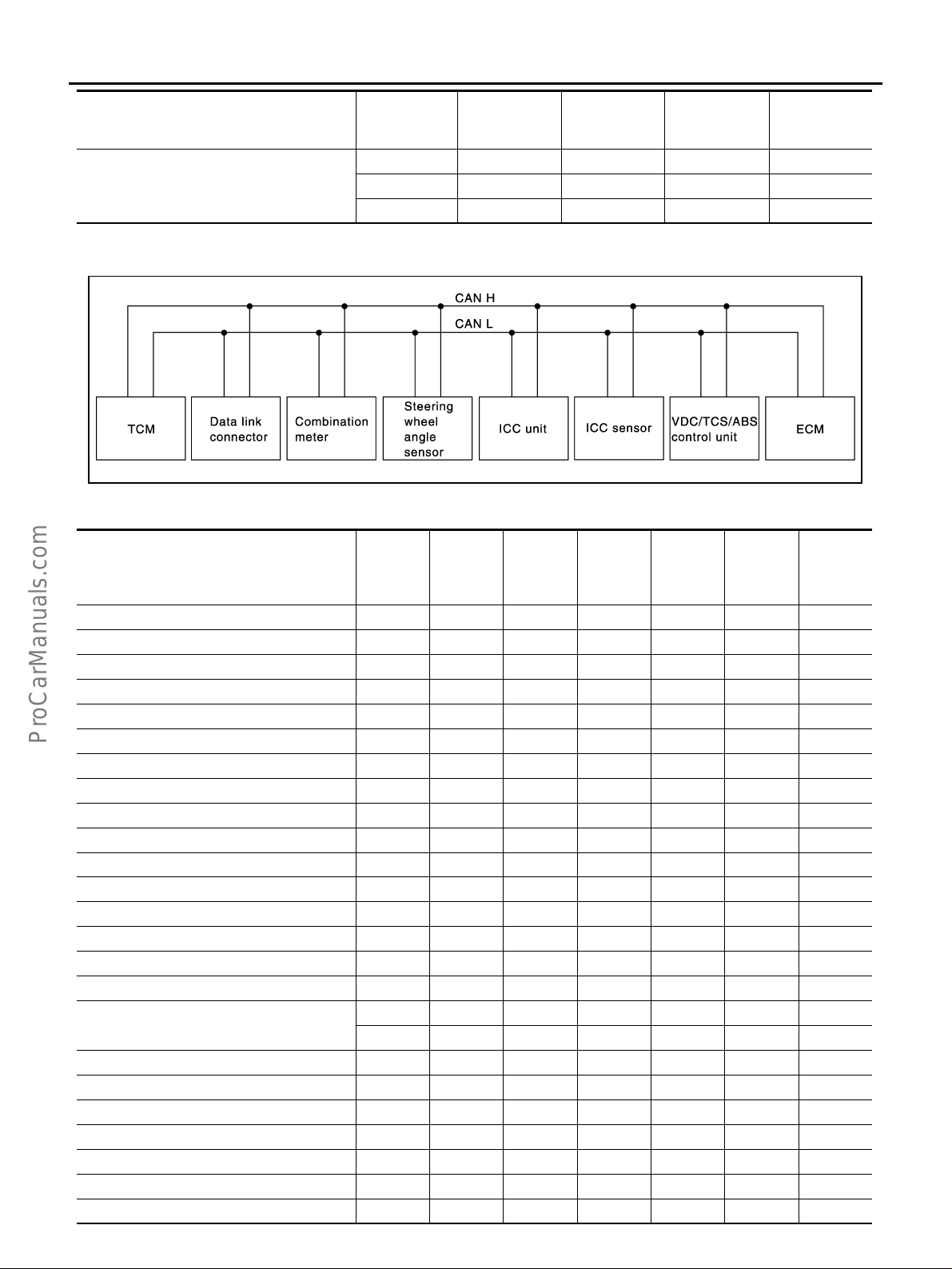
ENGINE CONTROL SYSTEM
VDC / TCS /
ABS control
unit
ECM
Vehicle speed signal
Signals TCM
RR T
RT R
TR
Combination
meter
Steering wheel
angle sensor
FOR ICC MODELS
System Diagram
SKIA1241E
Input/output Signal Chart
T: Transmit R: Receive
Steering
Signals TCM
ICC system display signal R T
ICC sensor signal R T
Engine speed signal R R R R T
Engine coolant temperature signal R R T
Accelerator pedal position signal R R T
Engine torque signal R R T
Battery voltage signal R T
Closed throttle position signal R R T
Lock-up prohibition signal R T
Torque -do w n per mission signal R T
Fuel consumption monitor signal R T
Lock-up signal T R
Hard deceleration signal T R
Torque -do w n sig nal T R
Power mode indicator signal T R
A/T fluid temperature warning lamp signal T R R
Current gear position signal
Next gear position signal T R R
Shift change signal T R R
Shift pattern signal T R R
VDC system control signal TR
VDC operation signal R T R
Stop lamp switch signal R T
Steering wheel angle sensor signal R T R R
RT
Combination meter
TR RR
wheel
angle
sensor
ICC unit
ICC sen-
sor
VDC /
TCS /
ABS con-
trol unit
ECM
Revision: 2004 April 2002 Q45
EC-32
ENGINE CONTROL SYSTEM
Steering
Signals TCM
Air conditioner switch signal T R
Headlamp switch signal T R
Rear window defogger switch signal T R
OD cancel switch signal R T R
Brake switch signal R T
Power mode switch signal R T
RR R T
Vehicle speed signal
RT R
TRR
Combina-
tion meter
wheel
angle
sensor
ICC unit
ICC sen-
sor
VDC /
TCS /
ABS con-
trol unit
ECM
A
EC
C
D
E
F
G
H
I
J
K
L
M
Revision: 2004 April 2002 Q45
EC-33
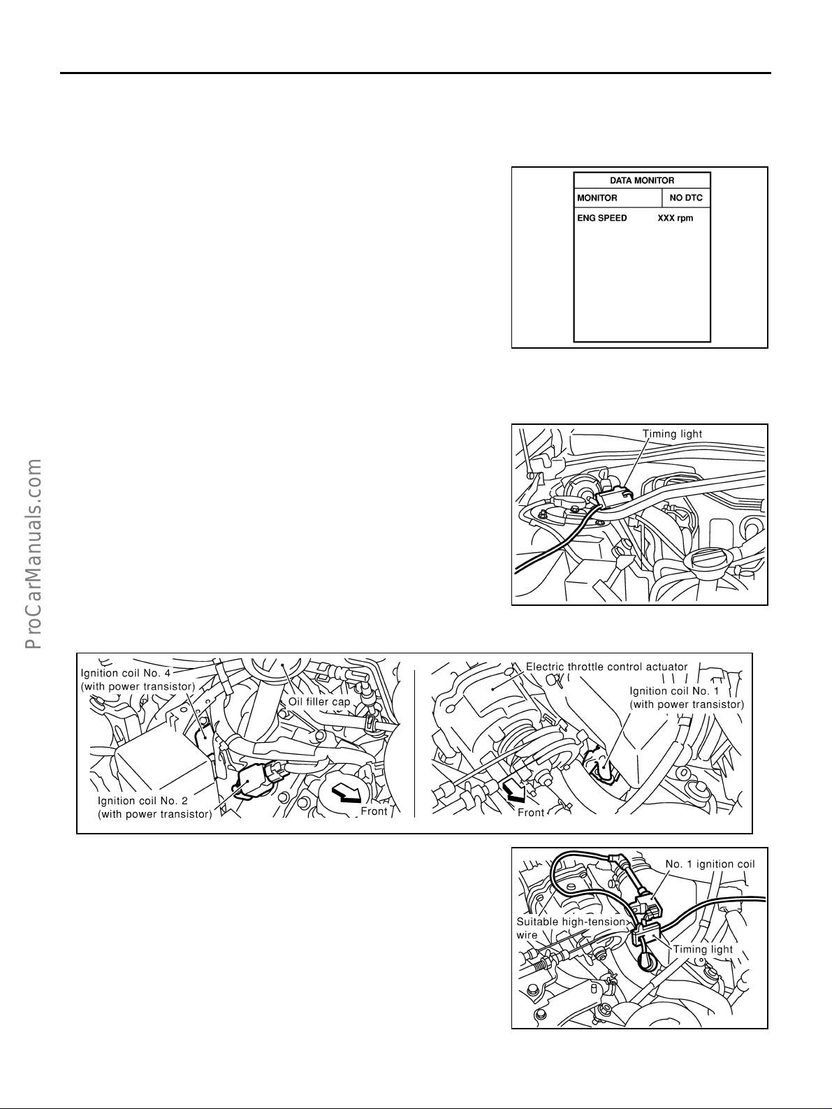
BASIC SERVICE PROCEDURE
BASIC SERVICE PROCEDURE PFP:00018 Idle Speed and Ignition Timing Check EBS000Q7
IDLE SPEED
Using CONSULT-II
Check idle speed in “DATA MONITOR” mode with CONSULT-II.
SEF058Y
IGNITION TIMING
Any of following two methods may be used.
Method A
1. Attach timing light to loop wire as shown.
2. Check ignition timing.
Method B
1. Remove No. 1 ignition coil.
2. Connect No. 1 ignition coil and No. 1 spark plug with suitable
high-tension wire as s ho wn, and attach timing li ght clamp to this
wire.
PBIB0139E
PBIB0033E
PBIB0140E
Revision: 2004 April 2002 Q45
EC-34
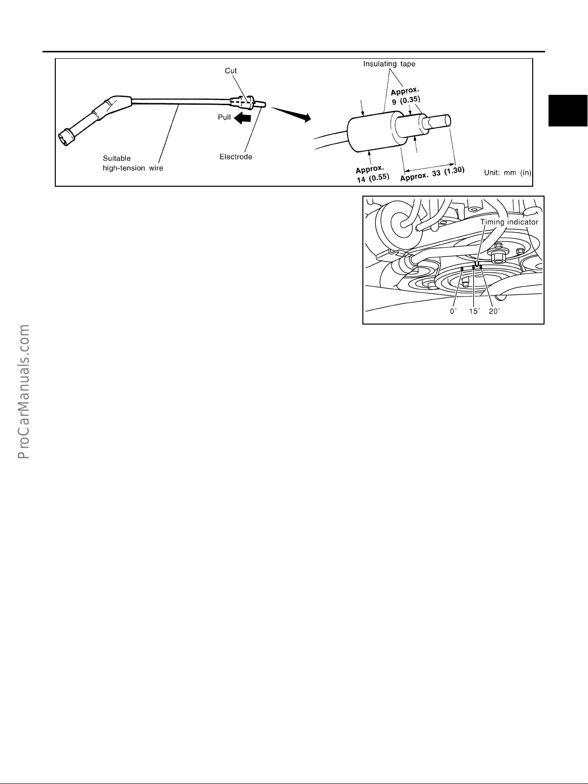
BASIC SERVICE PROCEDURE
A
EC
C
SEF011V
3. Check ignition timing.
Idle Speed/Ignition Timing/Idle Mixture Ratio Adjustment EBS000Q8
PREPARATION
1. Make sure that the following parts are in good order.
– Battery
– Ignition system
– Engine oil and coolant levels
– Fuses
– ECM harness connector
– Vacuum hoses
– Air intake system
(Oil filler cap, oil lev el ga ug e, etc .)
– Fuel pressure
– Engine compression
– Throttle valve
– Evaporative emission system
2. On air conditioner equipped models, checks should be carried out while the air conditioner is “OFF”.
3. On automatic transmission equipped models, when checking idle rpm, ignition timing and mixture ratio,
checks should be carried out whil e shift lever is in “N” position.
4. When measuring “CO” percentage, insert probe more than 40 cm (15.7 in) into tail pipe.
5. Turn off headlamps, heater blower, rear window defogger.
6. Keep front wheels pointed straight ahead.
D
E
F
G
PBIB0141E
H
I
J
K
L
M
Revision: 2004 April 2002 Q45
EC-35

BASIC SERVICE PROCEDURE
OVERALL INSPECTION SEQUENCE
PBIB0804E
Revision: 2004 April 2002 Q45
EC-36

BASIC SERVICE PROCEDURE
NOTE:
If a vehicle contains a part which is o perating outside of design spec ifications with no MIL illumin ation, the part shall not be replace d prior to emissio n testing unless it is determined that th e part has
been tampered with or abused in such a way that the diagnostic system cannot reasonably be
expected to detect the resulting malfunction.
INSPECTION PROCEDURE
A
EC
1. INSPECTION START
1. Check servic e records for any recent repairs that may indicate a related p roblem, or a curren t need for
scheduled maintenance.
2. Open engine hood and check the following:
– Harness connectors for improper connections
– Wiring harness for improper connections, pinches and cut
– V acuum hoses for splits, kinks and improper connections
– Hoses and ducts for leaks
– Air cleaner clog ging
– Gasket
3. Confirm that electrical or mechanical loads are not applied .
– Headlamp switch is OFF.
– Air conditioner swit ch is OFF.
– Rear window defogger switch is OFF.
– Steering wheel is in the straight-ahead position, etc.
4. Start engine and warm it up until engine coolant temperature
indicator points the middle of gauge.
Ensure engine stays below 1,000 rpm.
SEF983U
C
D
E
F
G
H
I
J
5. Run engine at about 2,000 rpm for ab out 2 minutes under no load.
6. Make sure that no DTC is displayed with CONSULT-II or GST.
OK or NG
OK >> GO TO 3.
NG >> GO TO 2.
2. REPAIR OR REPLACE
Repair or replace components as necessary according to corresponding “Diagnostic Procedure”.
>> GO TO 3.
K
SEF976U
L
M
SEF977U
Revision: 2004 April 2002 Q45
EC-37

BASIC SERVICE PROCEDURE
3. CHECK TARGET IDLE SPEED
With CONSULT-II
1. Run engine at about 2,000 rpm for about 2 min utes under no-load.
2. Rev engine (2,000 to 3,000 rpm) two or three times under noload, then run engine at idle speed for about 1 minute.
3. Read idle speed in “DATA MONITOR” mode with CONSULT-II.
650 ± 50 rpm (in “P” or “N” position)
SEF978U
Without CONSULT-II
1. Run engine at about 2,000 rpm for about 2 min utes under no-load.
2. Rev engin e ( 2,0 00 t o 3 ,0 00 r pm ) tw o or t hre e t i mes unde r no -lo ad , then r un en gine at i dl e s peed fo r ab out
1 minute.
3. Check idle speed.
650 ± 50 rpm (in “P” or “N” position)
OK or NG
OK >> GO TO 9.
NG >> GO TO 4.
4. PERFORM THROTTLE VALVE CLOSED POSITION LEARNING
1. Stop engine.
2. Perform EC-45, "
>> GO TO 5.
Throttle Valve Closed Position Learning" .
5. PERFORM IDLE AIR VOLUME LEARNING
Perform EC-45, "
Which is the result CMPLT or INCMP?
CMPLT or INCMP
CMPLT>> GO TO 6.
INCMP >> 1. Follow the const r uc tio n of “Idle Air Volume Learning”.
Idle Air Volume Learning" .
2. GO TO 4.
SEF058Y
Revision: 2004 April 2002 Q45
EC-38

BASIC SERVICE PROCEDURE
6. CHECK TARGET IDLE SPEED AGAIN
With CONSULT-II
1. Start engine and warm it up to normal operating temperature.
2. Read idle speed in “DATA MONITOR” mode with CONSULT-II.
650 ± 50 rpm (in “P” or “N” position)
Without CONSULT-II
1. Start engine and warm it up to normal operating temperature.
2. Check idle speed.
650 ± 50 rpm (in “P” or “N” position)
OK or NG
OK >> GO TO 9.
NG >> GO TO 7.
7. DETECT MALFUNCTIONING PART
Check the Followin g.
● Check camshaft position sensor (PHASE) and circuit. refer to EC-340 .
● Check crankshaft position sensor (POS) and circuit. refer to EC-331 , EC-490 .
OK or NG
OK >> GO TO 8.
NG >> 1. Repair or replace.
2. GO TO 4.
8. CHECK ECM FUNCTION
A
EC
C
D
E
F
G
H
I
1. Substitute another known-good ECM to check ECM function. (ECM may be the cause of a problem, but
this is the rar ely the case.)
2. Perform initializ at io n of IVIS (NATS) system and regist rati on of IVIS (NATS) ignition key IDs. Refer to EC-
65, "IVIS (Infiniti Vehicle Immobilizer System — NATS)" .
>> GO TO 4.
9. CHECK IGNITION TIMING
1. Run engine at idle.
2. Check ignition timing with a timing light.
17 ± 5° BTDC (in “P” or “N” position)
OK or NG
OK (With CONSUL T-II)>>GO TO 17.
OK (Without CONSULT-II)>>GO TO 18.
NG >> GO TO 10.
10. PERFORM THROTTLE VALVE CLOSED POSITION LEARNING
1. Stop engine.
2. Perform EC-45, "
Throttle Valve Closed Position Learning" .
J
K
L
M
>> GO TO 11.
Revision: 2004 April 2002 Q45
EC-39
BASIC SERVICE PROCEDURE
11. PERFORM IDLE AIR VOLUME LEARNING
Perform EC-45, "
Which is the result CMPLT or INCMP?
CMPLT or INCMP
CMPLT>> GO TO 12.
INCMP >> 1. Follow the const r uc tio n of “Idle Air Volume Learning”.
Idle Air Volume Learning" .
2. GO TO 4.
12. CHECK TARGET IDLE SPEED AGAIN
With CONSULT-II
1. Start engine and warm it up to normal operating temperature.
2. Read idle speed in “DATA MONITOR” mode with CONSULT-II.
650 ± 50 rpm (in “P” or “N” position)
Without CONSULT-II
1. Start engine and warm it up to normal operating temperature.
2. Check idle speed.
650 ± 50 rpm (in “P” or “N” position)
OK or NG
OK >> GO TO 13.
NG >> GO TO 15.
13. CHECK IGNITION TIMING AGAIN
1. Run engine at idle.
2. Check ignition timing with a timing light.
17 ± 5° BTDC (in “P” or “N” posi-
OK or NG
tion)
OK (With CONSULT-II)>>GO TO 17.
OK (Without CONSUL T-II)>>GO TO 18.
NG >> GO TO 14.
14. CHECK TIMING CHAIN INSTALLATION
Check timing chain installation. Refer to EM-45, "
OK or NG
OK >> GO TO 15.
NG >> 1. Repair the timing chain installation.
2. GO TO 4.
TIMING CHAIN" .
15. DETECT MALFUNCTIONING PART
Check the following.
● Check camshaft position sensor (PHASE) and circuit. refer to EC-340 .
● Check crankshaft position sensor (POS) and circuit. refer to EC-331 , EC-490 .
OK or NG
OK >> GO TO 16.
NG >> 1. Repair or replace.
2. GO TO 4.
Revision: 2004 April 2002 Q45
EC-40

BASIC SERVICE PROCEDURE
16. CHECK ECM FUNCTION
1. Substitute another known-good ECM to check ECM function. (ECM may be the cause of a problem, but
this is the rar ely the case.)
2. Perform initializ at io n of IVIS (NATS) system and regist rati on of IVIS (NATS) ignition key IDs. Refer to EC-
65, "IVIS (Infiniti Vehicle Immobilizer System — NATS)" .
>> GO TO 4.
17. CHECK HEAT ED OXYGEN SENSOR 1 (BANK 1) SIGNAL
With CONSULT-II
1. Run engine at about 2,000 rpm for about 2 minutes under no-load.
2. See “HO2S1 MNTR (B1)” in “DATA MONITOR” mode.
3. Running engine at 2,000 rpm under no-load (The engine is
warmed up to normal operating temperature.), check that the
monitor fluctuates between LEAN and RICH more than 5 times
during 10 sec onds.
1 time: RICH → LEAN → RICH
2 times: RICH → LEAN → RICH → LEAN → RICH
OK or NG
OK >> GO TO 19.
NG (Monitor does not fluctuate.)>>GO TO 21.
NG (Monitor fluctuates less than 5 times.)>>GO TO 28.
PBIB0120E
A
EC
C
D
E
F
G
H
18. CHECK HEAT ED OXYGEN SENSOR 1 (BANK 1) SIGNAL
Without CONSULT-II
1. Stop engine and set ECM to Self-diagnostic mode II (Heated oxygen sensor 1 monitor). Refer to EC-67,
"HOW TO SWITCH DIAGNOSTIC TEST MODE" .
2. Start engine and run it at about 2,000 rpm for about 2 minutes und er no-loa d.
3. Running engine at 2,000 rpm under no-load (The engine is warmed up to normal operating temperature.),
check that the MIL comes on more than 5 times during 10 seconds.
OK or NG
OK >> GO TO 20.
NG (MIL does not come on)>>GO TO 21.
NG (MIL comes on less than 5 times)>>GO TO 28.
19. CHECK HEAT ED OXYGEN SENSOR 1 (BANK 2) SIGNAL
With CONSULT-II
1. See “HO2S1 MNTR (B2)” in “DATA MONITOR” mode.
2. Running engine at 2,000 rpm under no-load (The engine is
warmed up to normal operating temperature.), check that the
monitor fluctuates between LEAN and RICH more than 5 times
during 10 sec onds.
1 time: RICH → LEAN → RICH
2 times: RICH → LEAN → RICH → LEAN → RICH
I
J
K
L
M
OK or NG
OK >> INSPECTION END
NG (Monitor does not fluctuate.)>>GO TO 22.
NG (Monitor fluctuates less than 5 times.)>>GO TO 28.
Revision: 2004 April 2002 Q45
EC-41
PBIB0120E

BASIC SERVICE PROCEDURE
20. CHECK HEATED OXYGEN SENSOR 1 (BANK 2) SIGNAL
Without CONSULT-II
1. Switch the monitored sensor from bank 1 to bank 2. Refer to EC-67, "
from Bank 1 to Bank 2 or Vice Versa" .
2. Running en gi n e at 2, 00 0 rpm und er no -l oa d (Th e en gi n e is warm ed up to norm al ope r ati ng tem pe rat u re. ),
check that the MIL comes on more than 5 times during 10 seconds.
OK or NG
OK >> INSPECTION END
NG (MIL does not come on)>>GO TO 22.
NG (MIL comes on less than 5 times)>>GO TO 28.
How to Switch Moni tored Sensor
21. CHECK HEATED OXYGEN SENSOR 1 (BANK 1) HARNESS
1. Turn ignition s witch “OFF” and disconnect battery ground cable.
2. Disconnect ECM harness connector.
3. Disconnect heated oxygen sensor 1 (bank 1) h arness connector.
4. Check harness conti nuity between ECM terminal 114 and heated oxygen sens or 1 (bank 1) terminal 1.
Refer to Wiring Diagram, EC-200, "
Continuity should exist.
BANK 1" .
5. Also check harness for short to ground and short to power.
OK or NG
OK >> GO TO 23.
NG >> 1. Repair or replace harness between ECM and heated oxygen sensor 1 (bank 1).
2. GO TO 4.
22. CHECK HEATED OXYGEN SENSOR 1 (BANK 2) HARNESS
1. Turn ignition s witch “OFF” and disconnect battery ground cable.
2. Disconnect ECM harness connector.
3. Disconnect heated oxygen sensor 1 (bank 2) h arness connector.
4. Check harness conti nuity between ECM terminal 115 and heated oxygen sens or 1 (bank 2) terminal 1.
Refer to Wiring Diagram, EC-202, "
Continuity should exist.
5. Also check harness for short to ground and short to power.
OK or NG
OK >> GO TO 23
NG >> 1. Repair or replace harness between ECM and heated oxygen sensor 1 (bank 2).
2. GO TO 4.
BANK 2" .
23. PERFORM THROTTLE VALVE CLOSED POSITION LEARNING
1. Reconnect ECM harness connector.
2. Perform EC-45, "
>> GO TO 24.
Revision: 2004 April 2002 Q45
Throttle Valve Closed Position Learning" .
EC-42

BASIC SERVICE PROCEDURE
24. PERFORM IDLE AIR VOLUME LEARNING
Refer to EC-45, "
Which is the result CMPLT or INCMP?
CMPLT or INCMP
CMPLT (With CONSULT-II)>>GO TO 25.
CMPLT (Without CONSULT-II) >>GO TO 26.
INCMP>> 1. Follow the construction of “Idle Air Volume Learning” .
Idle Air Volume Learning" .
2. GO TO 4.
25. CHECK “CO” %
With CONSULT-II
1. Start engine and warm it up until engine coolant temperature indicator points the middle of gauge.
2. Turn ignition switc h “OFF”, wait at least 10 seconds and then turn “ON” .
3. Select “ENG COOLANT TEMP” in “ACTIVE TEST” mode.
4. Set “ENG COOLANT TEMP” to 5°C (41°F) by touching “DW N”
and “Qd”.
5. Start engine and rev it (2,000 to 3,000 rpm) two or three times
under no-load, then run en gin e at id le sp ee d.
6. Check “CO” %.
Idle CO: 0.7 − 9.9 % and engine runs
smoothly.
A
EC
C
D
E
F
G
H
OK or NG
OK >> GO TO 28.
NG >> GO TO 27.
26. CHECK “CO” %
Without CONSULT-II
1. Start engine and warm it up until engine coolant temperature indicator points to the middle of gauge.
2. Turn ignition switch “OFF”.
3. Disconnect engine coolant temperature sensor harness connec tor.
4. Connect a resisto r (4.4 kΩ) betw ee n term in al s of engine coolant
temperature sensor harness connector.
5. Start engine and rev it (2,000 to 3,000 rpm) two or three times
under no-load, then run en gin e at id le sp ee d.
6. Check “CO” %.
Idle CO: 0.7 − 9.9 % and engine runs
smoothly.
7. After checking “CO” %, turn ignition switch “OFF”, disconnect
the resistor from the terminals of engine coolant temperature
sensor harness connector, and then connect engine coolant
temperature sensor harness connector to engi ne coolant temperature sensor.
OK or NG
OK >> GO TO 28.
NG >> GO TO 27.
SEF172Y
SEF982UA
I
J
K
L
M
Revision: 2004 April 2002 Q45
EC-43

BASIC SERVICE PROCEDURE
27. RECONNECT HEATED OXYGEN SENSOR 1 HARNESS CONNECTOR
1. T urn ignition switch “OFF”.
2. Reconnect heated oxygen sensor 1 harness connector.
>> GO TO 31.
28. REPLACE HEATED OXYGEN SENSOR 1
1. Stop engine.
2. Replace heated oxygen sensor 1 on the malfunctioning bank.
With CONSULT-II>>GO TO 29.
Without CONSULT-II>>GO TO 30.
29. CHECK HEATED OXYGEN SENSOR 1 (BANK 1) / (BANK 2) SIGNAL
With CONSULT-II
1. Start engine and warm it up until engine coolant temperature indicator points the middle of gauge.
2. See “HO2S1 MNTR (B1)/(B2)” in “DA TA MONITOR” mode.
3. Running en gi n e at 2, 00 0 rpm und er no -l oa d (Th e en gi n e is warm ed up to norm al ope r ati ng tem pe rat u re. ),
check that the monitor fluctuates between LEAN and RICH more than 5 times during 10 seconds.
1 time: RICH → LEAN → RICH
2 times: RICH → LEAN → RICH → LEAN → RICH
OK or NG
OK >> GO TO 4.
NG >> GO TO 31.
30. CHECK HEATED OXYGEN SENSOR 1 (BANK 1) / (BANK 2) SIGNAL
Without CONSULT-II
1. Set ECM to Self-diagnostic mode II (Heated oxygen sensor 1 monitor). Refer to EC-67, "
SWITCH DIAGNOSTIC TEST MODE" .
2. Switch the monitored sensor to the malfunctioning bank. Refer to EC-67, "
sor from Bank 1 to Bank 2 or Vice Versa" .
3. Running en gi n e at 2, 00 0 rpm und er no -l oa d (Th e en gi n e is warm ed up to norm al ope r ati ng tem pe rat u re. ),
check that the MIL comes on more than 5 times during 10 seconds.
OK or NG
OK >> GO TO 4.
NG >> GO TO 31.
How to Switch Monitored Sen-
HOW TO
31. DETECT MALFUNCTIONING PART
Check the following.
● Check fuel pressure regulator and repair or replace if necessary. Refer to EC-49 .
● Check mass air flow sensor and its circuit, and repair or replace if necessary. Refer to EC-154 .
● Check injector and its circuit, and repair or replace if necessary. Refer to EC-579 .
● Check engine coolant temperature sensor and its circuit, and repair or replace if necessary. Refer to EC-
173 and EC-193 .
OK or NG
OK >> GO TO 33.
NG >> 1. Repair or replace.
2. GO TO 32.
Revision: 2004 April 2002 Q45
EC-44

BASIC SERVICE PROCEDURE
32. ERASE UNNECESSARY DTC
After this inspection, unnecessary DTC mig ht be disp la yed.
Erase the stored memory in ECM and TCM. Refer to EC-63, "
HOW TO ERASE EMISSION-RELATED DIAG-
NOSTIC INFORMATION" and AT-37 .
>> GO TO 4.
33. CHECK ECM FUNCTION
1. Substitute another known-good ECM to check ECM function. (ECM may be the cause of a problem, but
this is the rar ely the case.)
2. Perform initializ at io n of IVIS (NATS) system and regist rati on of IVIS (NATS) ignition key IDs. Refer to EC-
65, "IVIS (Infiniti Vehicle Immobilizer System — NATS)" .
>> GO TO 4.
Throttle Valve Closed Position Learning EBS002R7
DESCRIPTION
“Throttle Valve Closed Position Learning ” is an operati on to learn the fully close d positio n of the throttl e valve
by monitorizi n g th e th rot t le p os it ion s en so r ou t pu t si gn al . I t must be per f orme d ea ch t i me har ne ss co nnec t or o f
electric throttle control actuator or ECM is disconnected.
OPERATION PROCEDURE
1. Turn ignition switch “ON”.
2. Turn ignition switch “OFF” wait at least 10 seconds.
Make sure that throttle valve moves during above 10 seconds by confirming the operating sound.
Idle Air Volume Learning EBS01AJ7
DESCRIPTION
“Idle Air Volume Learning” is an o perati on to le arn the idle air volume that ke eps each engine within the sp ecific range. It must be performed under any of the following conditions:
● Each time electric throttle control actuator or ECM is replaced.
● Idle speed or i gnition timing is out of specification.
PREPARATION
Before performing “Idle Air Volume Learning”, make sure that all of the following conditions are satisfied.
Learning will be cancelled if any of the following conditions are missed for even a moment.
● Battery voltage: More than 12 .9V (At idle)
● Engine coolant temperatu re: 70 - 99°C (158 - 210°F)
● PNP switch: ON
● Electric load switch: OFF
(Air conditioner, headlamp, rear window de fog ge r)
On vehicles equi pped with daytime light syste ms, set lighting switch t o the 1st position to light
only small lamps.
● Ste ering wheel: Ne utral (Straight-ahead position)
● Ve hicle speed: Stopped
● Transmission: Warmed-up
For models with C ONSULT-II, driv e vehicle until “FLUID TEM P SE” in “DATA MONITOR” mode of “A/T”
system indicates less than 0.9V.
For models without CONSULT-II, drive vehicle for 10 minutes.
A
EC
C
D
E
F
G
H
I
J
K
L
M
Revision: 2004 April 2002 Q45
EC-45
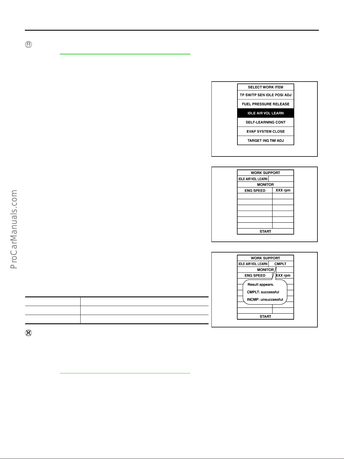
BASIC SERVICE PROCEDURE
OPERATION PROCEDURE
With CONSULT-II
1. Perform EC-45, "Throttle Valve Closed Position Learning" .
2. Start engine and warm it up to normal operating temperature.
3. Check that all items listed under the topic “PRE-CONDITIONING” (previously mentioned) are in good
order.
4. Select “IDLE AIR VOL LEARN” in “WORK SUPPORT” mode.
SEF452Y
5. Touch “START” and wait 20 seconds.
6. Make sure that “CMPLT” is displayed on CONSULT-II screen. If
“INCMP” is displaye d, “I dle Air Volume Learning” will not be car-
ried out successfully. In this case, find th e cause of th e problem
by referring to the “Diagnostic Procedure” below.
7. Rev up the engine two o r three times and make sure that idle
speed and ignition timing are within the specifications.
ITEM SPECIFICATION
Idle speed 650 ± 50 rpm (in “P” or “N” position)
Ignition timing 17 ± 5° BTDC (in “P” or “N” position)
Without CONSULT-II
NOTE:
● It is better to count the time accurately with a clock.
● It is impossible to switch the diagno stic mode when an accelerator pe dal position sensor circui t
has a malfunction.
1. Perform EC-45, "
2. Start engine and warm it up to normal operating temperature.
3. Check that all items listed under the topic “PRE-CONDITIONING” (previously mentioned) are in good
order.
4. Turn ignition s witch “OFF” and wait at least 10 se conds.
5. Confirm that accelerat or pedal is full y released, turn ignition swit ch “ON” and wait 3 seconds.
6. Repeat the following procedure quickly five times withi n 5 seconds.
a. Fully depress the accelerator pedal.
b. Fully release the accelerator pedal.
Throttle Valve Closed Position Learning" .
SEF454Y
SEF455Y
Revision: 2004 April 2002 Q45
EC-46
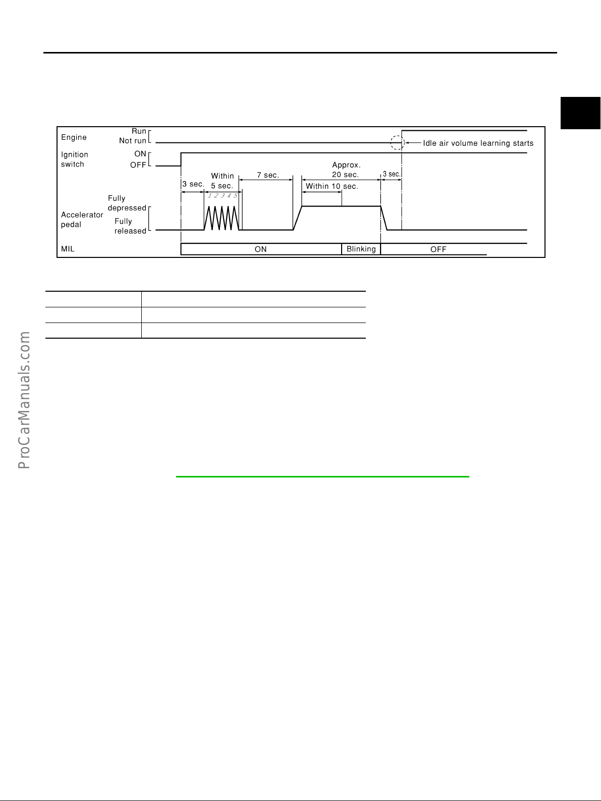
BASIC SERVICE PROCEDURE
7. Wait 7 seconds, fully de pre ss the ac ce lerator pedal and kee p it for approx. 20 se co nd s u ntil the MIL goes
off.
8. Fully release the accelerator pedal with in 3 seconds after the MIL goes off.
9. Start engine and let it idle.
10. Wait 2 0 seconds.
PBIB0091E
11. Rev up the engine two or three times and make sure that idle speed and ignition timing are within the
specifications.
ITEM SPECIFICATION
Idle speed 650 ± 50 rpm (in “P” or “N ” position)
Ignition timing 17 ± 5° BTDC (in “P” or “N” position)
12. If idle spee d and ignit ion ti ming are no t with in the spec ific ation , the re su lt will be inc omp lete. I n th is ca se,
find the cause of the problem by referring to t he “Diagnostic Procedure” below .
A
EC
C
D
E
F
G
H
DIAGNOSTIC PROCEDURE
If idle air volume learning cannot be performed successfully, proceed as follows:
1. Check that throttle valve is fully closed.
2. Check PCV valve operation.
3. Check that downstream of throttle valve is free from air leakage.
4. When the above three item s check out OK, engine co mponent parts and their installation condi-
tion are questionable. Check and eliminate the cause of the problem.
It is useful to perform EC-138, "
TROUBLE DIAGNOSIS - SPECIFICATION VALUE" .
5. If any of the following co nditions occur after the engine has started, eliminate the cause of the
problem and perform “Idle air volume learning” all over again:
– Engine stalls.
– Erroneous idle.
I
J
K
L
M
Revision: 2004 April 2002 Q45
EC-47

BASIC SERVICE PROCEDURE
Fuel Pressure Check EBS000QA
FUEL PRESSURE RELEASE
Before disconnecting fuel line, release fuel pressure from fuel line to eliminate danger.
With CONSULT-II
1. Turn ignition switch “ON”.
2. Perform “FUEL PRESSURE RELEASE” in “WORK SUPPORT”
mode with CONSULT-II.
3. Start engine.
4. After engine stalls, crank it two or three times to release all fuel
pressure.
5. T urn ignition switch “OFF”.
SEF214Y
Without CONSULT-II
1. Remove fuel pump fuse located in fuse box.
2. Start engine.
3. After engine stalls, crank it two or three times to release all fuel
pressure.
4. T urn ignition switch “OFF”.
5. Reinstall fuel pump fuse after serv icing fuel system.
FUEL PRESSURE CHECK
● When reconnecting fuel line, always use new clamps.
● Make sure that clamp screw does not contact adjacent parts.
● Use a torque driver to tighten clamps.
● Use Pressure Gauge to check fuel pressure.
● Do not perform fuel pressure check with system operating. Fuel pressure gauge may indicate
false readings.
● Do not use t he fuel hose for checking fuel pressure more than 30 times.
● Do not use the fuel hose for checking fuel pressure with damage or crack s on it.
1. Prepare a fuel hose for checking fuel pressure (Part No. 16511 6N210).
2. Cut this fuel hose at the middle and connect a fuel pressure gauge.
3. Release fuel pressure to zero.
4. Disconnect fuel hose between fuel pressure regulator and fuel tube to fuel tank.
PBIB0041E
PBIB0142E
Revision: 2004 April 2002 Q45
EC-48

BASIC SERVICE PROCEDURE
5. Install the pres sure gauge betw een fuel pressure re gulator and
fuel tube to the fuel tank as shown in the figure.
6. Start engine and check for fuel leakage.
7. Read the indication of fuel pressure gauge.
At idling:
With vacuum hose
connected
With vacuum hose
disconnected
If results are unsatisfactory, perform Fuel Pressure Regulator Check.
FUEL PRESSURE REGULATOR CHECK
1. Stop engine and disconnect fuel pressure regulator vacuum hose from vacuum gallery.
2. Plug vacuum gallery with a blind cap.
3. Connect variable vacuum source to fuel pressure regulator.
Approximately 23 5 kPa
(2.4 kg/cm
2
, 34 psi)
Approximately 29 4 kPa
2
(3.0 kg/cm
, 43 psi)
A
EC
C
PBIB0039E
D
E
F
G
4. Start engine and read indicat ion of fuel press ure gauge as vac uum is changed.
Fuel pressure shoul d decrease as vacuum in creases. If results
are unsatisfactory, replace fuel pressure regulator.
PBIB0038E
SEF718BA
H
I
J
K
L
M
Revision: 2004 April 2002 Q45
EC-49
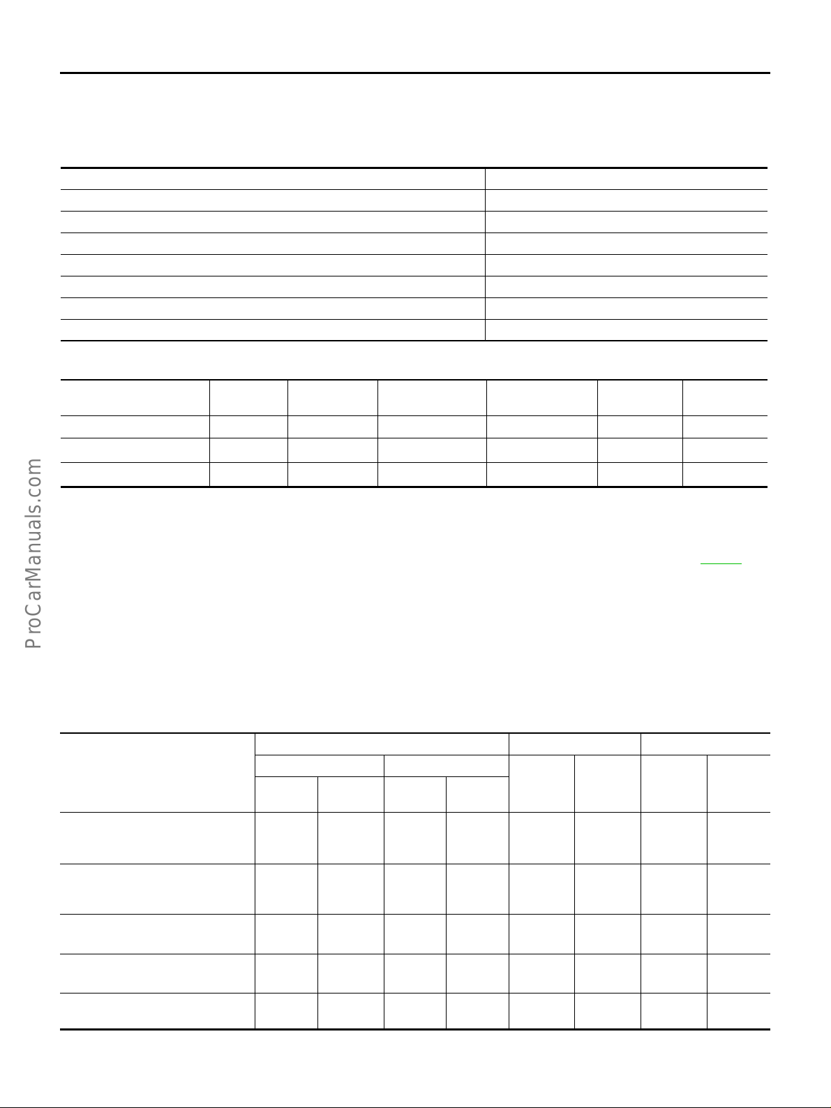
ON BOARD DIAGNOSTIC (OBD) SYSTEM
ON BOARD DIAGNOSTIC (OBD) SYSTEM PFP:00028 Introduction EBS001FA
The ECM has an on board diagnostic system, which detects malfunctions related to engine sensors or actuators. The ECM also records various emission-related diagnostic information including:
Emission-related diagnostic information SAE Mode
Diagnostic Trouble Code (DTC) Mode 3 of SAE J1979
Freeze Frame data Mode 2 of SAE J1979
System Readiness Test (SRT) code Mode 1 of SAE J1979
1st Trip Diagnostic Trouble Code (1st Trip DTC) Mode 7 of SAE J1979
1st Trip Freeze Frame data
Test values and Test limits Mode 6 of SAE J1979
Calibration ID Mode 9 of SAE J1979
The above information can be checked using procedures listed in the table below.
×: Applicable —: Not applicable
DTC 1st trip DTC
CONSULT-II ×× × × ×—
GST ×
ECM ×
1
×*
2
×*
Freeze Frame
data
× — ××
————
1st trip Freeze
Frame data
SRT code Test value
*1: 1st trip DTCs for self-diagnoses concerning SRT items can not be show n on the G S T displ ay.
*2: When DTC and 1st trip DTC simultaneously appear on the display, they cannot be clearly distinguished from each other.
The malfunction indicator lamp (MIL) on the instrument panel lights up when the same malfunction is detected
in two consecutive trips (Two trip detection logic), or when the ECM enters fail-safe mode. (Refer toEC-80
Two Trip Detection Logic EBS001FB
When a malfunction is detected for the first time, 1st trip DTC and 1st trip Freeze Frame data are stored in the
ECM memory. The MIL will not light up at this stage. <1st trip>
If the same malfunction is detected again durin g the next drive, the DTC and Freeze Fr ame data are sto red in
the ECM memory, and the MIL lights u p. The MIL ligh ts up at the same tim e when the DTC is stored. <2nd
trip> The “trip” in the “Two Trip Detection Logic” means a driving mode in which self-diagnosis is performed
during vehicle operation. Specific on board diagnostic items will cause the ECM to light up or blink the MIL,
and store DTC and Freeze Frame data, even in the 1st trip, as shown below.
×: Applicable —: Not applicable
MIL DTC 1st trip DTC
Items
Misfire (Possible three way catalyst damage) — DTC: P0300 P0308 is being detected
Misfire (Possible three way catalyst damage) — DTC: P0300 P0308 is being detected
Electric throttle control actuator
— DTC P1121, P1122*
Throttle control motor re la y
— DTC P1123*
Closed loop control
— DTC: P1148, P1168
2
2
1st trip 2nd trip
Blinking
× ————— × —
—— × —— × ——
———— × ———
———— × ———
— × —— × ———
Lighting
up
Blinking
Lighting
up
1st trip
displaying
2nd trip
displaying
1st trip
displaying
.)
2nd trip
display-
ing
Revision: 2004 April 2002 Q45
EC-50

ON BOARD DIAGNOSTIC (OBD) SYSTEM
MIL DTC 1st trip DTC
Items
Fail-safe items (Refer to EC-80
Except above — — — × — ××—
*1: Except “ECM”
*2: For type II or type III vehicle (Refer to EC-9, "
.) — × ——
1st trip 2nd trip
Blinking
Lighting
up
How to Check Vehicle Type" .).
Blinking
Lighting
up
1st trip
displaying
1
×*
2nd trip
displaying
—
1st trip
displaying
1
×*
Emission-related Diagnostic Information EBS001FC
EMISSION-RELATED DIAGNOSTIC INFORMATION ITEMS
×: Applicable —: Not applicable
1
DTC*
CONSULT-II
2
GST*
U1000
P0000 0000
P0100 0100 MAF SEN/CIRCUIT — — × EC-154
P0105 0105 ABSL PRES SEN/CIRC — — × EC-163
P0110 0110 AIR TEMP SEN/CIRC — — × EC-168
P0115 0115 COOLANT T SEN/CIRC — — × EC-173
P0120 0120 THRTL POS SEN/CIRC — —
P0121 0121 ACCEL POS SEN/CIRC — —
P0125 0125 *COOLANT T SEN/CIRC — — × EC-193
P0130 0130 HO2S1 (B1) ××
P0131 0131 HO2S1 (B1) ××
P0132 0132 HO2S1 (B1) ××
P0133 0133 HO2S1 (B1) ××
P0134 0134 HO2S1 (B1) ××
P0135 0135 HO2S1 HTR (B1) ××
P0137 0137 HO2S2 (B1) ××
P0138 0138 HO2S2 (B1) ××
P0139 0139 HO2S2 (B1) ××
P0140 0140 HO2S2 (B1) ××
P0141 0141 HO2S2 HTR (B1) ××
P0150 0150 HO2S1 (B2) ××
P0151 0151 HO2S1 (B2) ××
P0152 0152 HO2S1 (B2) ××
P0153 0153 HO2S1 (B2) ××
P0154 0154 HO2S1 (B2) ××
P0155 0155 HO2S1 HTR (B2) ××
P0157 0157 HO2S2 (B2) ××
ECM*
1000*
Items
3
5
(CONSULT-II screen terms)
CAN COMM CIRCUIT — — EC-151
NO DTC IS DETECTED.
FURTHER TESTING
MAY BE REQUIRED.
SRT code
——— —
Test value/
Test limit
(GST only)
1st trip
DTC*
6
×*
6
×*
4
×*
4
×*
4
×*
4
×*
4
×*
4
×*
4
×*
4
×*
4
×*
4
×*
4
×*
4
×*
4
×*
4
×*
4
×*
4
×*
4
×*
4
×*
1
Reference page
EC-178
EC-186
EC-197
EC-207
EC-213
EC-220
EC-232
EC-241
EC-249
EC-260
EC-271
EC-282
EC-293
EC-197
EC-207
EC-213
EC-220
EC-232
EC-241
EC-249
2nd trip
A
display-
ing
EC
—
C
D
E
F
G
H
I
J
K
L
M
Revision: 2004 April 2002 Q45
EC-51

1
DTC*
CONSULT-II
2
GST*
ECM*
P0158 0158 HO2S2 (B2) ××
P0159 0159 HO2S2 (B2) ××
P0160 0160 HO2S2 (B2) ××
P0161 0161 HO2S2 HTR (B2) ××
P0171 0171 FUEL SYS-LEAN/BK1 — — × EC-301
P0172 0172 FUEL SYS-RICH/BK1 — — × EC-309
P0174 0174 FUEL SYS-LEAN/BK2 — — × EC-301
P0175 0175 FUEL SYS-RICH/BK2 — — × EC-309
P0180 0180 FUEL TEMP SEN/CIRC — — × EC-316
P0300 0300 MULTI CYL MISFIRE — — × EC-321
P0301 0301 CYL 1 MISFIRE — — × EC-321
P0302 0302 CYL 2 MISFIRE — — × EC-321
P0303 0303 CYL 3 MISFIRE — — × EC-321
P0304 0304 CYL 4 MISFIRE — — × EC-321
P0305 0305 CYL 5 MISFIRE — — × EC-321
P0306 0306 CYL 6 MISFIRE — — × EC-321
P0307 0307 CYL 7 MISFIRE — — × EC-321
P0308 0308 CYL 8 MISFIRE — — × EC-321
P0325 0325 KNOCK SEN/CIRC-B1 — — × EC-327
P0330 0330 KNOCK SEN/CIRC-B2 — — × EC-327
P0335 0335 CKP SEN/CIRCUIT — — × EC-331
P0340 0340 CMP SEN/CIRCUIT — — × EC-340
P0420 0420 TW CATALYST SYS-B1 ××
P0430 0430 TW CATALYST SYS-B2 ××
P0440 0440 EVAP SMALL LEAK ××
P0443 0443 PURG VOLUME CONT/V — — × EC-360
P0446 0446 VENT CONTROL VALVE — — × EC-366
P0450 0450 EVAP SYS PRES SEN — — × EC-373
P0455 0455 EVAP GROSS LEAK ××
P0460 0460 FUEL LEV SEN SLOSH — — × EC-389
P0461 0461 FUEL LEVEL SENSOR — — × EC-394
P0464 0464 FUEL LEVL SEN/CIRC — — × EC-396
P0500 0500 VEH SPEED SEN/CIRC — — × EC-400
P0505 0505 ISC SYSTEM/FNCTN — — × EC-402
P0550 0550 PW ST P SEN/CIRC — — × EC-404
P0605 0605 ECM — — × EC-409
P0650 0650 MIL/CIRC — — × EC-412
P0705 0705 PNP SW/CIRC — — × AT-85
P0710 0710 ATF TEMP SEN/CIRC — — × AT-118
P0720 0720 VEH SPD SEN/CIR AT — — × AT-89
P0740 0740 TCC SOLENOID/CIRC — — × AT-94
ON BOARD DIAGNOSTIC (OBD) SYSTEM
Items
3
(CONSULT-II screen terms)
SRT code
Test value/
Test lim it
(GST only)
1st trip
DTC*
4
×*
4
×*
4
×*
4
×*
4
×*
4
×*
4
×*
4
×*
1
Reference page
EC-260
EC-271
EC-282
EC-293
EC-346
EC-346
EC-350
EC-381
Revision: 2004 April 2002 Q45
EC-52

ON BOARD DIAGNOSTIC (OBD) SYSTEM
1
DTC*
CONSULT-II
P1610 - P1615 1610 - 1615 NATS MALFUNCTION — — × BL-146
2
GST*
P0744 0744 A/T TCC S/V FNCTN — — × AT-97
P0745 0745 L/PRESS SOL/CIRC — — × AT-101
P1065 1065 ECM BACK UP/CIRC — — × EC-416
P1110 1110 INT/V TIM CONT-B1 — — × EC-420
P1111 1111 INT/V TI M V/CIR-B1 — — × EC-429
P1119 1119 RADI TEMP SEN/ CIRC — — × EC-435
P1121 1121 ETC ACTR — —
P1122 1122 ETC FUNCTION/CIRC — —
P1123 1123 ETC MOT RLY/CIRC — —
P1135 1135 INT/V TIM CONT-B2 — — × EC-420
P1136 1136 INT/V TIM V/CIR-B2 — — × EC-429
P1140 1140 INTK TIM S/CIRC-B1 — — × EC-452
P1145 1145 INTK TIM S/CIRC-B2 — — × EC-452
P1148 1148 CLOSED LOOP-B1 — — × EC-460
P1168 1168 CLOSED LOOP-B2 — — × EC-460
P1211 1211 TCS C/U FUNCTN — — × EC-462
P1212 1212 TCS/CIRC — — × EC-463
P1217 1217 ENG OVER TEMP — — × EC-464
P1220 1220 FPCM/CIRCUIT — — × EC-472
P1320 1320 IGN SIGNAL-PRIMARY — — × EC-479
P1336 1336 CKP SENSOR (COG) — — × EC-490
P1440 1440 EVAP SMALL LEAK ××
P1444 1444 PURG VOLUME CONT/V — — × EC-500
P1446 1446 VENT CONTROL VALVE — — × EC-509
P1447 1447 EVAP PURG FLOW/MON ××
P1448 1448 VENT CONTROL VALVE — — × EC-522
P1464 1464 FUEL LEVL SEN/CIRC — — × EC-530
P1480 1480 FAN CONT S/V CIRC — — × EC-534
P1490 1490 VC/V BYPASS/V — — × EC-540
P1491 1491 VC CUT/V BYPASS/V — — × EC-546
P1605 1605 A/T DIAG COMM LINE — — × EC-554
P1706 1706 P-N POS SW/CIRCUIT — — × EC-555
P1716 1716 TURBINE REV S/CIRC — — × AT-123
P1720 1720 V/SP SEN (A/T OUT) — — × EC-561
P1730 1730 A/T INTERLOCK — — × AT-129
P1752 1752 I/C SOLENOID/CIRC — — × AT-138
P1754 1754 I/C SOLENOID FNCTN — — × AT-141
P1757 1757 FR/B SOLENOID/CIRC — — × AT-144
P1759 1759 FR/B SOLENOID FNCT — — × AT-147
P1762 1762 D/C SOLENOID/CIRC — — × AT-150
P1764 1764 D/C SOLENOID FNCTN — — × AT-153
ECM*
3
(CONSULT-II screen terms)
Items
SRT code
Test value/
Test limit
(GST only)
1st trip
DTC*
6
×*
6
×*
6
×*
4
×*
4
×*
1
Reference page
EC-440
EC-443
EC-447
EC-498
EC-516
A
EC
C
D
E
F
G
H
I
J
K
L
M
Revision: 2004 April 2002 Q45
EC-53

ON BOARD DIAGNOSTIC (OBD) SYSTEM
1
DTC*
CONSULT-II
*1: 1st trip DTC No. is the same as DTC No.
*2: These numbers are prescribed by SAE J2012.
*3: In Diagnostic Test Mode II (Self-diagnostic results), these numbers are controlled by NISSAN.
*4: These are not displayed with GST.
*5: The trouble shooting for this DTC needs CONSULT-II.
*6: 1st trip DTC will not be displayed for type II and type III vehicles (Refer to EC-9, "
NOTE:
Regarding F50 models, “B1” or “BK1” indicates bank 1, “B2” or “BK2” indicates bank 2.
2
GST*
P1767 1767 HLR/C SOL/CIRC — — × AT-156
P1769 1769 HLR/C SOL/FNCTN — — × AT-159
P1772 1772 LC/B SOLENOID/CIRC — — × AT-162
P1774 1774 LC/B SOLENOID FNCT — — × AT-165
P1780 1780 SHIFT SIG FNCTN — — × EC-563
P1805 1805 BRAKE SW/CIRCUIT — — × EC-565
ECM*
3
(CONSULT-II screen terms)
Items
SRT code
DTC AND 1ST TRIP DTC
The 1st trip DTC (whose number is the same as the DTC number) is displayed for the latest self-diagnostic
result obtained. If the ECM memory w as cleared pre viously, and the 1st trip DTC did not re occur, the 1st trip
DTC will not be displayed.
If a malfunction is detected during the 1st trip, the 1st trip DTC is stored in the ECM memory. The MIL will not
light up (two trip detect ion logic ). If the sam e malfun ction is not detected in the 2nd tri p (meetin g the requi red
driving pattern), the 1 st trip DTC i s clear ed from the E CM me mory. If the same malfunction is detec ted in the
2nd trip, both the 1st trip DTC and DTC are stored in the ECM memory and the MIL lights up. In other words,
the DTC is stor e d in t h e ECM m emo ry an d the MI L lig hts up when the same mal f unct io n oc cur s i n tw o cons ecutive trips. If a 1st trip DTC is stored and a non-diagnostic operation is performed between the 1st and 2nd
trips, only the 1st trip DTC will continue to be stored. For malfunctions that blink or light up the MIL during the
1st trip, the DTC and 1st trip DTC are stored in the ECM memory.
Procedures for clearing the DTC and the 1st trip DTC from the ECM memory are described in “HOW TO
ERASE EMISSION-RELATED DIAGNOSTIC INFORMATION”, EC-63
For malfunctions in which 1st trip DTCs are displayed, refer to EC-51
ulations to continuously m onitor the syst em/component. In addition, the items moni tored non-con tinuously are
also displayed on CONSULT-II.
1st trip DTC is specified in Mode 7 of SAE J1979. 1st trip DTC detection occurs without lighting up the MIL and
therefore does not warn the driver of a problem. However, 1st trip DTC detection will not prevent the vehicle
from being tested, for example during Inspection/Maintenance (I/M) tests.
When a 1st trip DTC is detected, check, print out or write down and erase (1st trip) DTC and Freeze Frame
data as specified in “Work Flow” procedure Step II, refer to EC-75
dure” or “Overall Fu nction Check” to try to dupl icate the problem. If the malfunction is duplicat ed, the item
requires repair.
Test value/
Test lim it
(GST only)
How to Check Vehicle Type" .).
1st trip
DTC*
1
Reference page
.
. These items are req ui r ed by le ga l reg-
. Then perform “DTC Confirmation Proce-
How to Read DTC and 1st Trip DTC
DTC and 1st trip DTC can be read by the following methods.
With CONSULT-II
With GST
CONSULT-II or GST (Generic Scan Tool) Examples: P034 0, P1320, P0705 , P0750, etc.
These DTCs are prescribed by SAE J2012.
(CONSULT-II also displays the malfunctioning component or system.)
No Tools
The number of blinks of the M IL in the Diag nostic Te st Mode II (Self-D iagnostic Res ults) indicates the DTC.
Example: 0100, 1320 etc.
These DTCs are controlled by NISSAN.
● 1st trip DTC No. is the same as DTC No.
● Output of a DTC indicates a malfunction. However, GST or the Diagnostic Test Mode II do not indi-
cate whether the malfunction is still occurring or has occurred in the past and has returned to nor-
Revision: 2004 April 2002 Q45
EC-54

ON BOARD DIAGNOSTIC (OBD) SYSTEM
mal. CONSULT-II can id entify m alfunction status as shown below. Therefore, usin g CONSULT-I I (if
available) is recommended.
A sample of CONSULT-II display for DTC and 1st trip DTC is shown below. DTC or 1st trip DTC of a malfunction is displayed in SELF-DIAGNOSTIC RESULTS mode of CONSULT-II. T ime dat a indicates how many times
the vehicle was driven after the last detection of a DTC.
If the DTC is being detected currently, the time data will be “0”.
If a 1st trip DTC is stored in the ECM, the time data will be “[1t]”.
A
EC
C
D
E
SEF992X
FREEZE FRAME DATA AND 1ST TRIP FREEZE FRAME DATA
The ECM records the driving conditions such as fuel system status, calculated load value, engine coolant temperature, short term fuel trim, long term fuel trim, engine speed, vehicle speed, base fuel schedule and intake
air temperature at the moment a malfunction is detected.
Data which are stored in the ECM memory, along with the 1st trip DTC, are called 1st trip freeze frame data.
The data, stored toge ther with the DTC data, are called freeze fram e data and displaye d on CONSULT-I I or
GST. The 1st trip freeze frame data can only be displayed on the CONSULT-II screen, not on the GST. For
details, see EC-122
Only one set of freeze frame data (either 1st trip freeze frame data or freeze frame data) can be stored in the
ECM. 1st trip freeze frame data is stored in the ECM memory along with the 1st trip DTC. There is no priority
for 1st trip freeze fr ame data and it is update d each time a different 1st trip DTC is det ected. However, once
freeze frame data (2nd trip detection/MIL on) is stored in the ECM memory, 1st trip freeze frame data is no
longer stored. R eme mber, only one set of free ze fra me da ta can be stored in the ECM . The ECM has th e following pri orities to update the data.
Priority Items
1
2 Except the above items (Includes A/T related items)
3 1st trip freeze frame data
Freeze frame data Misfire — DTC: P0300 - P0308
For example, the EGR malfunction (Priority: 2) was detected and the freeze frame data was stored in the 2nd
trip. After that when the misfire (Priority: 1) is detected in another trip, the freeze frame data will be updated
from the EGR malfunction to the misfire. The 1st trip freeze frame data is updated each time a different malfunction is dete cted. There is no priority fo r 1st trip freeze frame data. However, once freeze frame data is
stored in the ECM memory, 1st trip freeze data is no longer stored (because only one freeze frame data or 1st
trip freeze frame data can be stored in the ECM). If freeze frame data is stored in the ECM memory and freeze
frame data with the same priority occurs later, the first (original) freeze frame data remains unchanged in the
ECM memory.
Both 1st trip freeze frame data and freeze frame data (along with the DTCs) are cleared when the ECM memory is erased. Procedures for clearing the ECM memory are described in “HOW TO ERASE EMISSIONRELATED DIAGNOSTIC INFORMATION”, EC-63
.
Fuel Injection System Function — DTC: P0171, P0172, P0174, P0175
.
F
G
H
I
J
K
L
M
SYSTEM READINESS TEST (SRT) CODE
System Readiness Test (SRT) code is specified in Mode 1 of SAE J1979.
As part of an enhanced em iss ions tes t for Ins pect ion & Ma inte nanc e (I/M), certain states req uire th e status of
SRT be used to indicate whether the ECM has completed self-diagnosis of major emission systems and components. Completion must be verified in or der for the emissions inspection to proceed.
If a vehicle is rejected for a State emissions inspection due to one or more SRT items indicating “INCMP”, use
the information in this Service Manual to set the SRT to “CMPLT”.
Revision: 2004 April 2002 Q45
EC-55

ON BOARD DIAGNOSTIC (OBD) SYSTEM
In most case s the EC M w il l a ut om atically comp le te its se lf-diagnosis cyc le d uri ng normal usage, and the SRT
status will indicate “CMPLT” for each application system. Once set as “CMPLT”, the SRT status remains
“CMPLT” until the self-diagnosis memory is erased.
Occasionally, certain portions of the se lf-diagnostic test may not be completed as a result of the customer' s
normal drivin g pattern; the SRT will indicate “I NCMP” for these items.
NOTE:
The SRT will also indicate “INCMP” if the self-diagnosis memory is erased f o r any reason or if the ECM memory power supply is interrupted for several hours.
If, during the state e missions insp ection, th e SRT indicates “CMPLT” for all test items, t he inspecto r will continue with the emissions test. However, if the SRT indicates “INCMP” for one or more of the SRT items the
vehicle is returned to the customer untested.
NOTE:
If MIL is “ON” during the state emissions inspection, the vehicle is also returned to the customer untested even
though the SRT indicates “CMPLT” for all test items. Therefore, it is important to check SRT (“CMPLT”) and
DTC (No DTCs) before the inspection.
Revision: 2004 April 2002 Q45
EC-56

ON BOARD DIAGNOSTIC (OBD) SYSTEM
SRT Item
The table below shows required self-diagnostic items to set the SRT to “CMPLT”.
SRT item
(CONSULT-II indica-
tion)
CATALYST 2 Three way catalyst function P0420, P0430
EVAP SYSTEM 1 EVAP control system (small leak) (negative pressure) P0440
HO2S 2 Heated oxygen sensor 1 (circ ui t) P0130, P0150
HO2S HTR 2 Heated oxygen sensor 1 heater P0135, P0155
*1: P1440 [EVAP control system (small leak) (positive pressure) diagnosis] is one ty pe of SRT related diagnosis. This diagno sis, however, does not contribute to setting the SRT as “CMPLT”, when no malfunction exists in the EVAP system. Therefore, P0440 must be
used instead of P1440.
*2: If completion of several SRTs is required, perform driving patterns (DTC confirmation procedure), one by one based on the priority for
models with CONSULT-II.
Perfor-
mance Pri-
ority*2
— EVAP control system (small leak) (positive pressure) P1440*1
2 EVAP control system purge flow monitoring P1447
Required self-diagnostic items to set the SRT to “CMPLT”
Heated oxygen sensor 1 (lean shift monitoring) P0131, P0151
Heated oxygen sensor 1 (rich shift monitoring) P0132, P0152
Heated oxygen sensor 1 (response monito ring) P0133, P0153
Heated oxygen sensor 1 (high voltage) P0134, P0154
Heated oxygen sensor 2 (min. voltage monitoring) P0137, P0157
Heated oxygen sensor 2 (max. voltage monitoring) P0138, P0158
Heated oxygen sensor 2 (response monito ring) P0139, P0159
Heated oxygen sensor 2 (high voltage) P0140, P0160
Heated oxygen sensor 2 heater P0141, P0161
Corresponding DTC
No.
A
EC
C
D
E
F
G
H
I
SRT Set Timing
SRT is set as “CMPLT” after self-diagnos is has been performed one or m ore times. Completion of SRT is
done regardless of whether the result is OK o r NG. The set timing is different between OK and NG results and
is shown in the table below.
Example
Self-diagnosis result
All OK Case 1 P0400 OK (1) — (1) OK (2) — (2)
Case 2 P0400 OK (1 ) — (1) — (1) — (1)
NG exists Case 3 P0400 OK OK — —
OK: Self-diagnosis is carried out and the result is OK.
Diagnosis
P0402 O K (1 ) — (1) — (1) OK (2)
P1402 OK (1) OK (2) — (2) — (2)
SRT of EGR “CMPLT” “CMPLT” “CMPLT” “CMPLT”
P0402 — (0) — (0) OK (1) — (1)
P1402 OK (1) OK (2) — (2) — (2)
SRT of EGR “INCMP” “INCMP” “CMPLT” “CMPLT”
P0402 — — — —
P1402 NG — NG
(1st trip)
DTC
SRT of EGR “INCMP” “INCMP” “INCMP” “CMPLT”
← ON → OFF ← ON → OFF ← ON → OFF ← ON →
1st trip DTC — 1st trip DTC
Ignition cycle
NG
(Consecutive
NG)
DTC
(= MIL “ON”)
J
K
L
M
Revision: 2004 April 2002 Q45
EC-57

ON BOARD DIAGNOSTIC (OBD) SYSTEM
NG: Self-diagnosis is carried out and the result is NG.
—: Self-diagnosis is not carried out.
When all SRT related self-diagnoses showed OK results in a single cycle (Ignition OFF-ON-OFF), the SRT will
indicate “CMPLT”. → Case 1 above
When all SRT related self-diagnoses showed OK results through several different cycles, the SRT will indicate
“CMPLT” at the time the respective self-diagnoses have at least one OK result. → Case 2 above
If one or more SRT related self-diagnoses showed NG results in 2 consecutive cycles, the SRT will also indicate “CMPLT”. → Case 3 above
The table above s hows that the mi nimum number of cycles for setting SRT as “INCMP” is one (1) f or each
self-diagnosis (Case 1 & 2) or two (2) for one of self-diagnoses (Case 3). However, in preparation for the state
emissions inspection, it is unnecessary for each self-diagnosis to be executed twice (Case 3) for the following
reasons:
● The SRT will indicate “CMPLT” at the time the respective self-diagnoses have one (1) OK result.
● The emissions inspection requires “CMPLT” of the SRT only with OK self-diagnosis results.
● When, during SRT driving pattern, 1st trip DTC (NG) is detected prior to “CMPLT” of SRT, the self-diagno-
sis memory must be erased from ECM after repair.
● If the 1st trip DTC is erased, all the SRT will indicate “INCMP”.
NOTE:
SRT can be set as “CMPLT” together with the DTC(s). Therefore, DTC check must always be carried out
prior to the state emission inspection even though the SRT indicates “CMPLT”.
SRT Service Procedure
If a vehicle has failed the state emissions inspection due to one or more SRT items indicating “INCMP”, review
the flowchart diagnostic sequence on the next page.
Revision: 2004 April 2002 Q45
EC-58

ON BOARD DIAGNOSTIC (OBD) SYSTEM
A
EC
C
D
E
F
G
*1 EC-54 *2 EC-59 *3 EC-57
How to Display SRT Code
With CONSULT-II
Selecting “SRT STATUS” in “DTC CONFIRMATION” mode with
CONSULT-II.
For items whose SRT codes are set, a “CMPLT” is displayed on the
CONSULT-II screen; for items whose SRT codes are not set,
“INCMP” is displayed.
A sample of CONSULT-II display for SRT code is shown at right.
“INCMP” means the se lf-d ia gnosis is incompl ete a nd SRT is no t s et .
“CMPLT” means the self-diagnosis is comple te and SRT is set.
With GST
Selecting Mode 1 with GST (Generi c Scan Tool)
H
I
J
K
L
M
SEF573XA
SEF935Z
Revision: 2004 April 2002 Q45
EC-59

ON BOARD DIAGNOSTIC (OBD) SYSTEM
How to Set SRT Code
To set all SRT codes, self-diagnosis for the items indicated above must be performed one or more times. Each
diagnosis may require a long period of actual driving under various conditions.
With CONSULT-II
Perform correspon di ng D T C Co nfi r m ati on Pro c ed ure o ne b y on e ba s ed o n “Perf orm an ce Prio rity ” i n th e table
on EC-57
Without CONSULT-II
The most efficient driving pattern in which SRT codes can be properly set is explained on the next page. The
driving pattern should be performed one or more times to set all SRT codes.
.
Revision: 2004 April 2002 Q45
EC-60
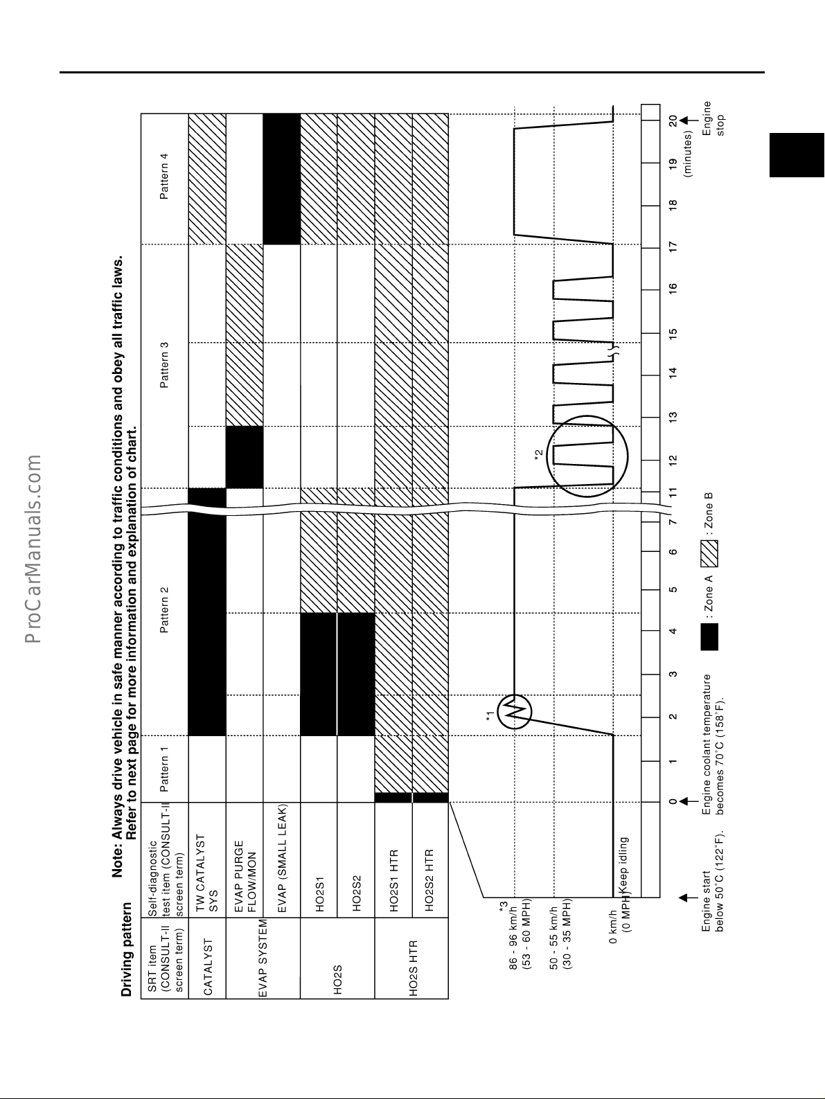
Driving Pattern
ON BOARD DIAGNOSTIC (OBD) SYSTEM
A
EC
C
D
E
F
G
H
I
J
K
L
M
PBIB0123E
Revision: 2004 April 2002 Q45
EC-61

ON BOARD DIAGNOSTIC (OBD) SYSTEM
● The time requ i red for e ach di agno si s va rie s wit h road sur fa ce co nd i tio ns, wea the r, altitude, individ ua l dri v-
ing habits , etc.
Zone A refers to the range where the time, required for the diagnosis under normal conditions*, is the
shortest.
Zone B refers to the range whe re the diagnosis can s till be performed if the di agnosis is not complet ed
within zone A.
*: Normal conditions refer to the following:
● Sea level
● Flat road
● Ambient air temperature: 20 - 30°C (68 - 86°F)
● Diagnosis is performed as qu ickly as possible under normal conditions.
Under different condition s [For exam ple: ambien t air temp erature oth er than 20 - 30°C (68 - 86°F)], diag nosis may also be per formed.
Pattern 1:
● The engine is started at the engine coolant temperature of −10 to 35°C (14 to 95°F)
(where the voltage between the ECM terminal 121 and ground is 3.0 - 4.3V).
● The engine must be operated a t idle speed until the engine coolant t emperature is greater than
70°C (158°F) (where the voltage between the ECM terminal 121 and ground is lower than 1.4V).
● The engine is started at the fuel tank temperature of warmer than 0°C (32°F) (where the voltage
between the ECM terminal 92 and ground is less than 4.1V).
Pattern 2:
● When steady-state driving is performed again even after it is int errupted, each diagnosis can be con-
ducted. In this case, the time required for diagnosis may be extended.
Pattern 3:
● The driving pattern outlined in *2 must be repeated at least 3 times.
Pattern 4:
● Tests are performed after the engine has been operated for at least 17 minutes.
● The accelerator pedal mus t be held very steady during steady -state driving.
● If the accelerator pedal is moved, the test must be conducted all over again.
*1: Depress the accelerator pedal until vehicle speed is 90 km/h (56 MPH), then release the accelerator pedal
and keep it released for more than 10 seconds. Depress the accelerator pedal until vehicle speed is 90 km/h
(56 MPH) again.
*2: Operate the vehicle in the following driving pattern.
1. Decelerate vehicle to 0 km/h (0 MPH) and let engine idle.
2. Repeat driving pattern shown at right at least 10 times.
– During acceleration, hold the accelerator pedal as steady as
possible.
SEF414S
*3: Checking the vehicle speed with GST is advised.
Suggested Transmission Gear Position for A/T Models
Set the selector lever in the “D” position with the overdrive switch turned ON.
Revision: 2004 April 2002 Q45
EC-62

ON BOARD DIAGNOSTIC (OBD) SYSTEM
TEST VALUE AND TEST LIMIT (GST ONLY — NOT APPLICABLE TO CONSULT-II)
The following is the inform ation specified in Mode 6 of SAE J1979.
The test value is a parameter used to determine whether a system/circuit diagnostic test is “OK” or “NG” while
being monitored by the ECM during self-diagnosis. The test limit is a reference value which is specified as the
maximum or minimum value and is compared with the test value being monitored.
Items for which these data (test value and test limit) are displayed are the same as SRT code items (30 test
items).
These data (test value an d test lim it) are spe cified b y Test ID (TID) and Comp onent ID (C ID) and ca n be displayed on the GST screen.
×: Applicable —: Not applicable
SRT item Self-diagnostic test item
CATALYST
EVAP SYSTEM
HO2S
EVAP control system purge flow monitor-
Heated oxygen sensor 1 heater (Bank 1)
Heated oxygen sensor 1 heater (Bank 2)
HO2S HTR
Heated oxygen sensor 2 heater (Bank 1)
Heated oxygen sensor 2 heater (Bank 2)
Three way catalyst function (Bank1) 01H 01H Max. ×
Three way catalyst function (Bank2) 03H 02H Max. ×
EVAP control system (Small leak) 05H 03H Max. ×
ing
Heated oxygen sensor 1 (Bank 1)
Heated oxygen sensor 1 (Bank 2)
Heated oxygen sensor 2 (Bank 1)
Heated oxygen sensor 2 (Bank 2)
Test va lue (GST displ ay)
TID CID
06H 83H Min. ×
09H 04H Max. ×
0AH 84H Min. ×
0BH 04H Max. ×
0CH 04H Max. ×
0DH 04H Max. ×
11H 05H Max. ×
12H 85H Min. ×
13H 05H Max. ×
14H 05H Max. ×
15H 05H Max. ×
19H 86H Min. ×
1AH 86H Min. ×
1BH 06H Max. ×
1CH 06H Max. ×
21H 87H Min. ×
22H 87H Min. ×
23H 07H Max. ×
24H 07H Max. ×
29H 08H Max. ×
2AH 88H Min. ×
2BH 09H Max. ×
2CH 89H Min. ×
2DH 0AH Max. ×
2EH 8AH Min. ×
2FH 0BH Max. ×
30H 8BH Min. ×
Test limit Application
A
EC
C
D
E
F
G
H
I
J
K
L
M
HOW TO ERASE EMISSION-RELATED DIAGNOSTIC INFORMATION
How to Erase DTC ( With CONSULT-II)
The emission related diagnostic information in the ECM can be erased by selecting “ERASE” in the “SELFDIAG RESULTS” mode with CONSULT-II.
If DTCs are displayed for both ECM and TCM (Transmission control module), they need to be erased individually from the ECM and TCM (Transmission control module).
Revision: 2004 April 2002 Q45
EC-63

ON BOARD DIAGNOSTIC (OBD) SYSTEM
NOTE:
If the DTC is not for A/T related items (see EC-10
1. If the ignition switch s tays “ON” aft er repair wo rk, be s ure to tur n ignit ion swi tch “OFF” on ce. Wait at least
10 seconds and t hen turn it “ON” (engine stopped) again.
2. Turn CONSULT-II “ON” and touch “A/T”.
3. Touch “SELF-DIAG RESULTS”.
4. Touch “ERASE”. [The DTC in the TCM (Transmission control module) will be erased.] Then touch “BACK”
twice.
5. Touch “ENGINE”.
6. Touch “SELF-DIAG RESULTS”.
7. Touch “ERASE”. (The DTC in the E CM will be erased.)
), skip steps 2 through 4.
SCIA5671E
How to Erase DTC ( With GST)
The emission related diagnostic information in the ECM can be erased by selecting Mode 4 with GST.
NOTE:
If the DTC is not for A/T related items (see EC-10
1. If the ignition switch s tays “ON” aft er repair wo rk, be s ure to tur n ignit ion swi tch “OFF” on ce. Wait at least
10 seconds and t hen turn it “ON” (engine stopped) again.
2. Perform “SELF-DIAGNOSTIC PROCEDURE (Without CONSULT-II)” in AT section titled “TROUBLE
DIAGNOSIS”, “Self-diagno sis”. (The engi ne warm-up step can be skipped w hen performing t he diagnosis
only to erase the DTC.)
3. Select Mode 4 with GST (Generic Scan Tool).
How to Erase DTC ( No Too ls)
1. If the ignition switch stays “ON” after repair work, be sure to turn ignition switch “OFF” once.
), skip step 2.
Revision: 2004 April 2002 Q45
EC-64

ON BOARD DIAGNOSTIC (OBD) SYSTEM
2. Wait at least 10 seconds and then turn it “ON” (engine stopped) again.
3. Change the di agnostic test mod e from Mode II to Mode I by depressing the acce lerator pedal. Refer to
EC-67, "
HOW TO SWITCH DIAGNOSTIC TEST MODE" .
A
● If the battery is disconnected, the emission-related diagnostic information will be lost after
approx. 24 hours.
● The following data are cleared when the ECM memory is erased.
1. Diagnostic trouble codes
2. 1st trip diagnostic trouble codes
3. Freeze frame data
4. 1st trip freeze frame data
5. System readiness test (SRT) codes
6. Te st va lu es
7. Others
Actual work procedures are explained using a DTC as an example. Be careful so that not only the DTC, but all
of the data listed above, are cleared from the ECM memory during work procedures.
IVIS (Infiniti Vehicle Immobilizer System — NATS) EBS001FD
● If the security indicator li ghts up with the ignition switch in
the “ON” position or “NATS MALFUNCTION” is displayed
on “SELF-DIAG RESULTS” screen, perform self-diagnostic
results mode with CONSULT-II using NATS program card.
Refer to BL-146, "
SYSTEM-NATS)" .
● Confirm no self-diagnostic results of IVIS (NATS) is dis-
played before touching “ERASE” in “SELF-DIAG RESULTS”
mode with CONSULT-II.
● When replacing ECM, initialization of IVIS (NATS) system
and registration of all IVIS (NATS) ignition key IDs must be
carried out with CONSULT-II using NATS program card.
Therefore, be sure to receive all keys from vehicle owner. Regarding the procedures of IVIS (NATS)
initialization and IV IS (NATS) igni tion key ID registration, refer to CONSULT-II operation manual,
IVIS/NVIS.
IVIS (INFINITI VEHICLE IMMOBILIZER
SEF543X
EC
C
D
E
F
G
H
I
J
K
Malfunction Indicator Lamp (MIL) EBS001FE
DESCRIPTION
The MIL is located on the instrument panel.
1. The MIL wil l light up when the ig nition s witch is tu rned ON without the engine running. This is a bulb check.
● If the MIL does not light up, refer to DI-27, "WARNING LAMPS" ,
or see EC-412
2. When the engi ne is started, the MIL should go off.
If the MIL remains on, the on board diagnostic system has
detected an engine system malfunction.
ON BOARD DIAGNOSTIC SYSTEM FUNCTION
The on board diagnostic system has the following four functions.
Revision: 2004 April 2002 Q45
.
SEF217U
EC-65
L
M
ON BOARD DIAGNOSTIC (OBD) SYSTEM
Diagnostic Test
Mode
Mode I Igni tion swit ch in
Mode II Ignition switch in
KEY and ENG.
Status
“ON” position
Engine stopped
Engine running MALFUNCTION
“ON” position
Function Explanation of Function
BULB CHECK This function checks the MIL bulb for damage (blown,
open circuit, etc.).
If the MIL does not come on, check MIL circuit.
This is a usual driving condition. When a malfu nct io n is
WARNING
SELF-DIAGNOSTIC
RESULTS
detected twice in two consecutiv e drivi ng cyc le s (t wo tr ip
detection logic), the MIL will light up to info rm th e driver
that a malfunction has been detected.
The following malfunctions will light up or blink the MI L in
the 1st trip.
● “Misfire (Possible three way catalyst damage)”
● “Closed loop control”
● Fail-safe mode
This function allows DTCs and 1st trip DTCs to be read.
Engine stopped
Engine running HEATED OXYGEN SENSOR 1
MONITOR
This function allows the fuel mixture condi tion (lea n or
rich), monitored by heated oxygen sensor 1, to be read.
MIL Flashing without DTC
If the ECM is in Diagnostic Test Mode II, MIL may flash when engine is running. In this case, check ECM diagnostic test mode. EC-67, "
How to switch the diagnosti c tes t (fu nc tion) modes, a nd de tails o f the above fu nc tio ns a re described later.EC-
67 .
The following emission-related diagnostic information is cleared when the ECM memory is erased.
1. Diagnost ic trouble codes
2. 1st trip diagnostic trouble codes
3. Freeze frame data
4. 1st trip freeze frame data
5. System readiness test (S RT) codes
6. Test values
7. Others
HOW TO SWITCH DIAGNOSTIC TEST MODE" .
Revision: 2004 April 2002 Q45
EC-66

ON BOARD DIAGNOSTIC (OBD) SYSTEM
HOW TO SWITCH DIAGNOSTIC TEST MODE
NOTE:
● It is better to count the time accurately with a clock.
● It is impossible to switch the diagnostic mode when an acce lerator pedal position sensor circ uit
has a malfunction.
● Always ECM returns to Diagnostic Test Mode I after ignition switch is turned “OFF”.
A
EC
How to Set Diagnostic Test Mode II (Self-diagnostic Results)
1. Confirm that accelerator pedal is fully released, turn ignition switch “ON” and wait 3 seconds.
2. Repeat the following procedure quickly five times within 5 seconds.
a. Fully depress the accelerator pedal.
b. Fully release the accelerator pedal.
3. Wait 7 se con ds , ful l y dep res s th e ac cel era t or pe da l an d ke ep it for appr ox . 10 sec on ds unt il the MI L starts
blinking.
4. Fully release the accelerator pedal.
ECM has entered to Diagnostic Test Mode II (Self-diagnostic results).
PBIB0092E
How to Set Diagnostic Test Mode II (Heated Oxygen Sensor 1 Monitor)
1. Set the ECM in Diagnostic Test Mode II (Self-diagnostic results). Refer to EC-67, "How to Set Diagnostic
Test Mode II (Self-diagnostic Results)" .
2. Start Engine.
ECM has entered to Diagnosti c Test Mode II (Heated oxygen sensor 1 monitor).
ECM will start heated oxygen sensor 1 monitoring from the bank 1 sensor.
How to Switch Monitored Senso r from Bank 1 to Bank 2 or Vice Versa
1. Fully depress the accelerator pedal quickl y and then releas e it immediately.
2. Make sure that monitoring sensor has changed by MIL blinking as follows.
C
D
E
F
G
H
I
J
K
L
PBIB0093E
How to Erase Diagnostic Test Mo de II (Self-diagnostic Results)
1. Set ECM in Diagnostic Test Mode II (Self-diagnostic results). Refer to EC-67, "How to Set Diagnostic Test
Mode II (Self-diagnostic Results)" .
2. Fully depress the accelerator pedal and keep it for more than 10 seconds .
The emission-related diagnostic information has been erased from the backup memory in the ECM.
3. Fully release the accelerator pedal, and confirm the DTC 0000 is displayed.
Revision: 2004 April 2002 Q45
EC-67
M

ON BOARD DIAGNOSTIC (OBD) SYSTEM
DIAGNOSTIC TEST MODE I — BULB CHECK
In this mode, the MI L on the in strumen t panel should stay ON. If it rem ains OFF, check the bulb. Refer to DI-
27, "WARNING LAMPS" or see EC-412 .
DIAGNOSTIC TEST MODE I — MALFUNCTION WARNING
MIL Condition
ON When the malfunction is detected or the ECM 's CPU is malf unct ioni ng.
OFF No ma lfunction.
● These DTC numbers are clarified in Diagnostic Test Mode II (SELF-DIAGNOSTIC RESULTS)
DIAGNOSTIC TEST MODE II — SELF-DIAGNOSTIC RESULTS
In this mode, the DTC and 1st trip DTC are indicated by the number of blinks of the MIL as shown below.
The DTC and 1st trip DTC are displayed at the same time. If the MIL does not illuminate in diagnostic test
mode I (Malfunction warning), all displayed items are 1st trip DTCs. If only one code is displayed when the MIL
illuminates in diagnostic test mode II (S ELF-DIAGNOSTI C RESULTS), it is a DTC; if two o r more codes are
displayed, they may be either DTCs or 1st trip DTCs. DTC No. is same as that of 1st trip DTC. These unidentified codes can be identified by using the CONSULT-II or GST. A DTC will be used as an example for how to
read a code.
A particular trouble code can be identified by the number of four-digit numeral flashes. The “zero” is indicated
by the number of ten flashes. The length of time the 1,000th-digit numeral flashes on and off is 1.2 seconds
consisting of an ON (0.6-second) - OFF (0.6-second) cycle.
The 100th-digit numeral and lower digit numerals consist of a 0.3-second ON and 0.3-second OFF cycle.
A change from on e dig it numera l to an other o ccu rs at an interv al of 1 .0-se cond OFF. In other words, the later
numeral appears on the display 1.3 seconds after t he former numeral has disappeared.
A change from one trouble code to another occurs at an interval of 1.8-second OFF.
In this way, all the detected malfunctions are classified by their DTC numbers. The DTC “0000” refers to no
malfunction. (See EC-10, "
How to Erase Diagnostic Test Mode II (Self-diagnostic Results)
The DTC can be erased from the back up memory in the EC M by dep ress ing ac cele rator pe dal. Re fer to EC-
67, "HOW TO SWITCH DIAGNOSTIC TEST MODE" .
● If the battery is disconnected, the DTC will be lost from the backup memory after approx 24 hours.
● Be careful not to erase the stored memory before starting trouble diagnoses.
INDEX FOR DTC" )
SEF952W
Revision: 2004 April 2002 Q45
EC-68

ON BOARD DIAGNOSTIC (OBD) SYSTEM
DIAGNOSTIC TEST MODE II — HEATED OXYGEN SENSOR 1 MONITOR
In this mode, the MIL displays the condition of the fuel mixture (lean or rich) which is monitored by the heated
oxygen sensor 1.
MIL Fuel mixture condition in the exhaust gas Air fuel ratio feedback control condition
ON Lean
OFF Rich
*Remains ON or OFF Any condit ion Open loop system
*: Maintains conditions just before switching to open lo op.
Closed loop system
A
EC
C
To check the heated oxygen sensor 1 function, start engine in the Diagnosti c Test Mode II and warm i t up until
engine coolant temperature indicator points to the middle of the gauge.
Next run engine at about 2,000 rpm for about 2 minutes under no-load conditions. Then make sure that the
MIL comes ON more t han 5 times within 10 seconds with engine running at 2,000 rpm under no-load.
OBD System Operation Chart EBS001FF
RELATIONSHIP BETWEEN MIL, 1ST TRIP DTC, DTC, AND DETECTABLE ITEMS
● When a malfuncti on is detecte d for the first time , the 1st trip DTC and the 1st trip free ze frame data are
stored in the ECM memory.
● When the same malfunction is detected in two consecutive trips, the DTC and the freeze frame data are
stored in the ECM me mory, and th e MIL will come on. For details, refe r to EC-50, "
Logic" .
● The MIL will go off after the vehi cle is drive n 3 tim es with no ma lfunc tion . Th e drive is coun te d only w hen
the recorded driving pattern is met (as stored in the ECM). If another malfunction occurs while counting,
the counter will reset.
● The DTC and the freeze frame data will be stored until the vehicle is driven 40 times (driving pattern A)
without the same malfunction recurring (except f or Misfire and Fuel Injection Sys tem). For Misfire and
Fuel Injection System, the DTC and freeze frame data will be stored until the vehicle is driven 80 times
(driving pattern C) without the same malfunction recurring. The “TIME” in “SELF-DIAGNOSTIC
RESULTS” mode of CONSULT-II will count the number of times the vehicle is driven.
● The 1st trip DTC is not displayed when the self-diagnosis results in “OK” for the 2nd trip.
SUMMARY CHART
MIL (goes off) 3 (pattern B) 3 (pattern B) 3 (pattern B)
DTC, Freeze Frame Data (no
display)
1st Trip DTC (clear) 1 (pattern C), *1 1 (pattern C), *1 1 (pattern B)
1st Trip Freeze Frame Data
(clear)
For details about patterns “B” and “C” under “Fuel Injection System ” and “Mis fire ”, see EC-71 .
For details about patterns “A” and “B” under “Other”, see EC-73 .
*1: Clear timing is at the moment OK is detected.
*2: Clear timing is when the same malfunction is detec ted in the 2nd tri p.
Items Fuel Injection System Misfire Other
80 (pattern C) 80 (pattern C) 40 (pattern A)
*1, *2 *1, *2 1 (pattern B)
Two Trip Detection
D
E
F
G
H
I
J
K
L
M
Revision: 2004 April 2002 Q45
EC-69
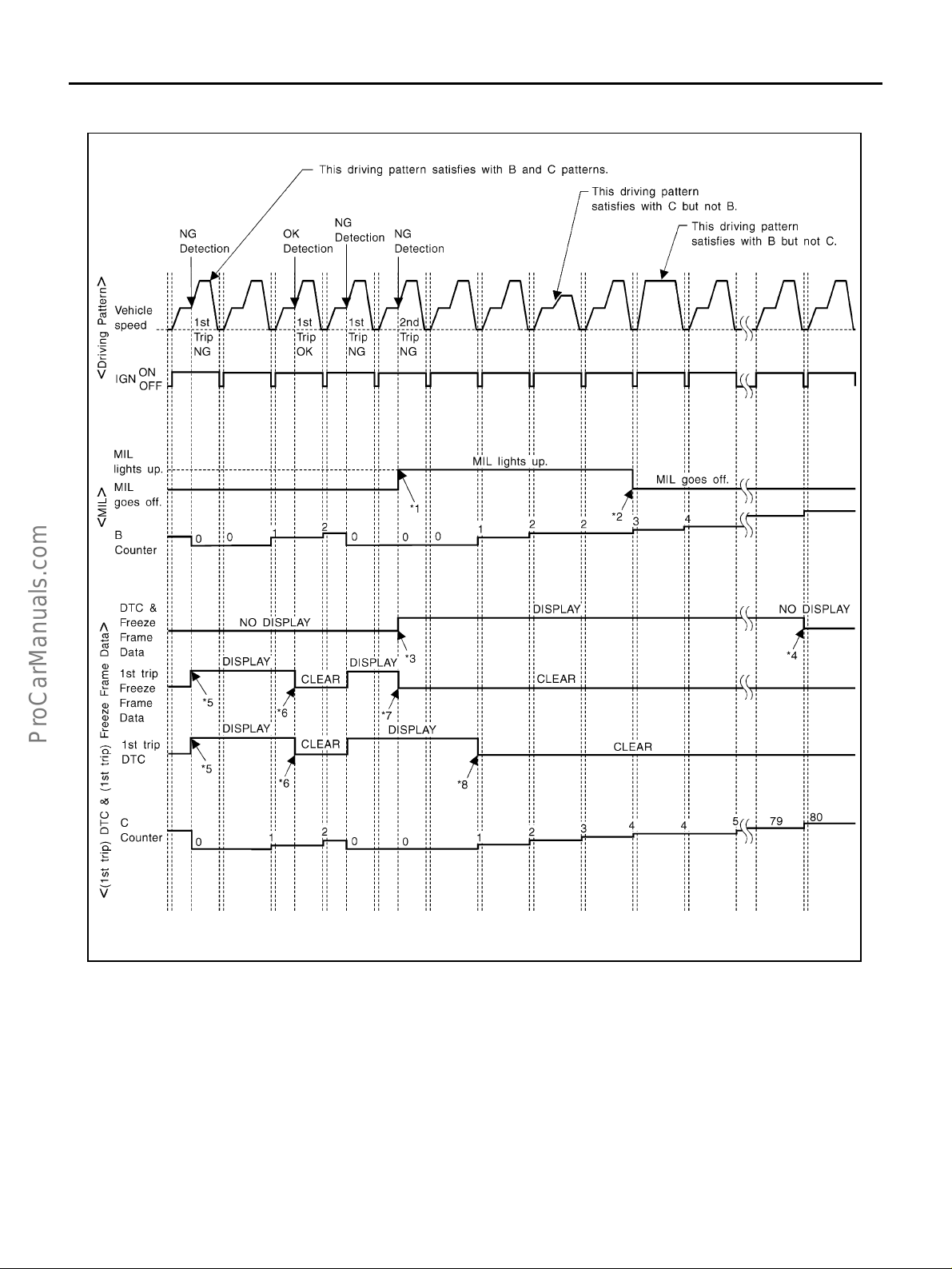
ON BOARD DIAGNOSTIC (OBD) SYSTEM
RELATIONSHIP BETWEEN MIL, DTC, 1ST TRIP DTC AND DRIVING PATTERNS FOR “MISFIRE” <EXHAUST QUALITY DETERIORATION>, “FUEL INJECTION SYSTEM”
*1: When the same malfunction is
detected in two consecutive trips,
MIL will light up.
*4: The DTC and the freeze frame data
will not be displayed any longer after
vehicle is driven 80 times (pattern C)
without the same malfunction. (The
DTC and the freeze frame data still
remain in ECM.)
*7: When the same malfunction is
detected in the 2nd trip, the 1st trip
freeze frame data will be cleared.
*2: MIL will go off after vehicle is driven
3 times (pattern B) without any malfunctions.
*5: When a malfunction is detected fo r
the first time, the 1st trip DTC and
the 1st trip freeze frame data will be
stored in ECM.
*8: 1st trip DTC will be cleared when
vehicle is driven once (pattern C)
without the same malfunction after
DTC is stored in ECM.
SEF392S
*3: When the same malfunction is
detected in two consecutive trips, the
DTC and the freeze frame data will
be stored in ECM.
*6: The 1st trip DTC and the 1st trip
freeze frame data will be cleared at
the moment OK is detected.
Revision: 2004 April 2002 Q45
EC-70

ON BOARD DIAGNOSTIC (OBD) SYSTEM
EXPLANATION FOR DRIVING PATTERNS FOR “MISFIRE <EXHAUST QUALITY DETERIORATION>”, “FUEL INJECTION SYSTEM”
<Driving Pattern B>
Driving pattern B means the vehicle operation as follows:
All component s and systems should be monitored at l east once by the OBD syst em.
● The B counter will be cleared when the malfunction is detected once regardless of the driving pattern.
● The B counter will be counted up when driving pattern B is satisfied without any malfunction.
● The MIL will go off when the B counter reaches 3. (*2 in “OBD SYSTEM OPERATION CHART”)
<Driving Pattern C>
Driving pattern C means the veh ic le opera tio n as foll ow s :
1. The following conditions should be satisfied at the same time:
Engine speed: (Engine speed in the freeze frame data) ±375 rpm
Calculated load value: (Calculated load value in the freeze frame data) x (1±0.1) [%]
Engine coolant temperature (T) condition :
● When the freeze frame data shows lower than 70°C (158°F), “T” should be lower than 70°C (158°F).
● When the freeze fram e data shows higher than or equal to 70°C (158°F), “ T” should be higher tha n or
equal to 70°C (158°F).
Example:
If the stored freeze frame data is as follows:
Engine speed: 850 rpm, Calculated load value: 30%, Engine coolant temperature: 80°C (176°F)
To be satisfied with driving pattern C, the vehi cle should run under the following conditions:
Engine speed: 475 - 1,225 rpm, Calculated load value: 27 - 33%, Engine coolant temperature: more than 70°C
(158°F)
● The C counter w ill be cleared when the malfunction is detecte d regardless of (1).
● The C counter w ill be counted up when (1) is sati sfied without the same malfunct ion.
● The DTC will not be displayed after C counter reaches 80.
● The 1st trip DTC will be cleared when C counter is counted once without the same malfunction after DTC
is stored in ECM.
A
EC
C
D
E
F
G
H
I
J
K
L
M
Revision: 2004 April 2002 Q45
EC-71
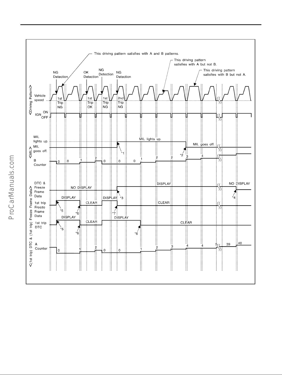
ON BOARD DIAGNOSTIC (OBD) SYSTEM
RELATIONSHIP BETWEEN MIL, DTC, 1ST TRIP DTC AND DRIVING PATTERNS EXCEPT FOR,
“MISFIRE <EXHAUST QUALITY DETERIORATION>”, “FUEL INJECTION SYSTEM”
*1: When the same malfunction is
detected in two consecutive trips,
MIL will light up.
*4: The DTC and the freeze frame data
will not be displayed any longer after
vehicle is driven 40 times (pattern A)
without the same malfunction.
(The DTC and the freeze frame data
still remain in ECM.)
*7: When the same malfunction is
detected in the 2nd trip, the 1st trip
freeze frame data will be cleared.
*2: MIL will go off after vehicle is driven
3 times (pattern B) without any malfunctions.
*5: When a malfunction is detected fo r
the first time, the 1st trip DTC and
the 1st trip freeze frame data will be
stored in ECM.
SEF393SD
*3: When the same malfunction is
detected in two consecutive trips, the
DTC and the freeze frame data will
be stored in ECM.
*6: 1st trip DTC will be cleared after
vehicle is driven once (pattern B)
without the same malfunction.
Revision: 2004 April 2002 Q45
EC-72

ON BOARD DIAGNOSTIC (OBD) SYSTEM
EXPLANATION FOR DRIVING PATTERNS EXCEPT FOR “MISFIRE <EXHAUST QUALITY
DETERIORATION>”, “FUEL INJECTION SYSTEM”
<Driving Pattern A>
A
EC
C
D
E
F
● The A counter will be cleared when the malfunction is detected regardless of (1) - (4).
● The A counter will be counted up when (1) - (4) are satisfied without the same malfunction.
● The DTC will not be displayed after the A counter reaches 40.
<Driving Pattern B>
Driving pattern B means the vehicle operation as follows:
All component s and systems should be monitored at l east once by the OBD syst em.
● The B counter will be cleared when the malfunction is detected once regardless of the driving pattern.
● The B counter will be counted up when driving pattern B is satisfied without any malfunctions.
● The MIL will go off when the B counter reaches 3 (*2 in “OBD SYS TEM OPERATION CHART”).
AEC574
G
H
I
J
K
L
M
Revision: 2004 April 2002 Q45
EC-73

TROUBLE DIAGNOSIS
TROUBLE DIAGNOSIS PFP:00004 Trouble Diagnosis Introduction EBS000QB
INTRODUCTION
The engine has an ECM to control major systems such as fuel control, ignition co ntrol, idle air control system, etc. The ECM accepts
input signals from sensors and instantly drives actuators. It is essential that both input and output signals are proper and stable. At the
same time, it is important that there are no problems such as vacuum leaks, fouled spark plugs, or other problems with the engine.
MEF036D
It is much more difficult to diagn ose a problem th at occurs intermi ttently rather than continuously. Most intermittent problems are
caused by po or electric connec tio ns o r i mp r op er w iri ng . I n this case,
careful checking of suspected circuits may help prevent the replacement of good parts.
A visual check only may not find the cause of the problems. A road
test with CONSULT-II (or GST) or a circuit tester connec ted should
be performed. Follow the “Work Flow” on EC-75
Before undertaking a ctual checks, take a fe w minutes to talk with a
customer who approaches with a driveability complaint. The customer can supply good information about such problems, especially
intermittent ones. Find out what symptoms are present and under
what condition s they occur. A “Diagnostic Worksheet” l ik e t he ex am ple EC-77
Start your diagnosis by looking for “conventional” problems first. This
will help troubleshoot driveability problems on an electronically controlled engine vehicle.
should be used.
.
SEF233G
SEF234G
Revision: 2004 April 2002 Q45
EC-74

WORK FLOW
Flow Chart
TROUBLE DIAGNOSIS
A
EC
C
D
E
F
G
*1 EC-80 *2 If time dat a of “ SELF-DIAG
RESULTS” is other than “0” or “[1t]”,
perform EC-142, "TROUBLE DIAG-
NOSIS FOR INTERMITTENT INCIDENT" .
*4 If the on board diagnostic system
cannot be performed, check main
power supply and ground circuit.
Refer to EC-143, "POWER SUPPLY
CIRCUIT FOR ECM" .
*7 EC-138
*5 If malfunctioning part cannot be
detected, perform EC-142, "
BLE DIAGNOSIS FOR INTERMITTENT INCIDENT" .
TROU-
SEF510ZG
*3 If the incident cannot be verified, per-
form EC-142, "
SIS FOR INTERMITTENT
INCIDENT" .
*6 EC-61
TROUBLE DIAGNO-
H
I
J
K
L
M
Revision: 2004 April 2002 Q45
EC-75
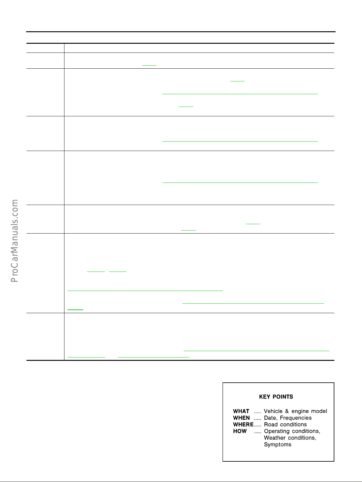
Description for Work Flow
STEP DESCRIPTION
STEP I
STEP II
STEP III
STEP IV
STEP V
STEP VI
STEP VII
Get detailed information about the conditions and the environment when the incident/symptom occurred using the
“DIAGNOSTIC WORK SHEET”, EC-76
Before confirming the concern, check and write down (print out using CONSULT-II or GST) the (1st trip) DTC and the
(1st trip) freeze frame data, then erase the DTC and the data. (Refe r to EC-63
freeze frame data can be used when duplicating the inciden t at STEP III & IV.
If the incident cannot be verified, perform EC-142, "
Study the relationship between the cause, specified by (1st trip) DTC, and t he sym pt om described by the customer.
(The “Symptom Matrix Chart” will be useful. See EC-86 .)
Also check related service bulletins for informat i on.
Try to confirm the symptom and under what conditions the incide nt oc cur s.
The “DIAGNOSTIC WORK SHEET” and the freeze frame data are useful to verify the incident. Connect CONSULT -II
to the vehicle in DATA MONITOR (AUTO TRIG) mode and check real time diagnosis results.
If the incident cannot be verified, perform EC-142, "
If the malfunction code is detected, skip STEP IV and perform STEP V.
Try to detect the (1st trip) DTC by driving in (or performing) the “DTC Confirmation Procedure”. Check and read the
(1st trip) DTC and (1st trip) freeze frame data by using CONS U LT-II or GST.
During the (1st trip) DTC verification, be sure to connect CONSULT-II to the vehicle in DATA MONITOR (AUTO TRIG)
mode and check real time diagnosis res ults.
If the incident cannot be verified, perform EC-142, "
In case the “DTC Confirmation Procedure ” is not available, per for m the “Ov era ll Func tion Check” instead. The (1st
trip) DTC cannot be displayed by this check, however, this simplified “check” is an effective alternative.
The “NG” result of the “Overall Function Check” is the sam e as t he (1s t trip) DTC det ect ion.
Take th e appr opr ia te action based on the results of STEP I through IV.
If the malfunction code is indicated, proceed to TROUBLE DIAGNOSIS FOR DTC PXXXX.
If the normal code is indicated, proceed to the BASIC INSPECTION. (Refer to EC-82
according to the Symptom Matrix Chart. (Refe r to EC-86
Identify where to begin diagnosis based on the relationship study between symptom and possible causes. Inspect the
system for mechanical binding, loose connectors or wiring damage using (tracing) “Harness Layouts”.
Gently shake the related connectors, components or wiring harness with CONSULT-II set in “DATA MONITOR
(AUTO TRIG)” mode.
Check the voltage of the related ECM terminals or monitor the output data from the related sensors with CONSULT-II.
Refer to EC-109
The “Diagnostic Procedure” in EC section contains a descr i ption based on open circuit inspection. A short circuit
inspection is also required for the circuit check in the Diagnostic Procedure. For details, refer to “Circuit Inspection” in
How to Perform Efficient Diagnosis for an Electrical Incident" .
GI-26, "
Repair or replace the malfunction parts.
If malfunctioning part cannot be detected, perfor m EC-142, "TROUBLE DIAGNOSIS FOR INTERMITTENT INCI-
DENT" .
Once you have repaired the circuit or replaced a comp onent, you need to run the engine in the same conditions and
circumstances which resulted in the customer's initial complaint.
Perform the “DTC Confirmation Procedure” and confirm the normal code [DTC No. P0000] is detected. If the incident
is still detected in the final check, perform STEP VI by using a m ethod di fferent from the previous one.
Before returning the vehicle to the customer, be sure to erase the unnecessary (alre ady f ix ed) (1st trip ) DTC in ECM
and TCM (Transmission control module). (Refer to EC-63, "
INFORMATION" and AT-37, "HOW TO ERASE DTC" .)
TROUBLE DIAGNOSIS
.
.) The (1st trip) DTC and the (1st trip)
TROUBLE DIAGNOSIS FOR INTERMITTENT INCIDENT" .
TROUBLE DIAGNOSIS FOR INTERMITTENT INCIDENT" .
TROUBLE DIAGNOSIS FOR INTERMITTENT INCIDENT" .
.) Then perform inspections
.)
, EC-133 .
HOW TO ERASE EMISSION-RELATED DIAGNOSTIC
DIAGNOSTIC WORKSHEET
Description
There are many operating conditions that lead to the malfunction of
engine compone nt s. A go od gr asp of such c ondi tio ns can make t roubleshooting f aster and more accurate.
In general, each customer feels differently about a problem. It is
important to fully understand the symptoms or conditions for a customer complaint.
Utilize a diagn osti c wo rksh eet li ke th e one on th e ne xt page in ord er
to organize all the information for troubl eshooting.
Some condition s may caus e the M IL to com e on st ea dy or bl ink an d
DTC to be detected. Examples:
● V ehicle ran out of fuel, which caused the engine to misfire.
Revision: 2004 April 2002 Q45
EC-76
SEF907L

TROUBLE DIAGNOSIS
● Fuel filler cap was left off or incorrectly screwed o n, allowing fuel to evaporate into the atmosphere.
Worksheet Sample
A
EC
C
D
E
F
G
H
I
J
K
L
M
MTBL0017
Revision: 2004 April 2002 Q45
EC-77

TROUBLE DIAGNOSIS
DTC Inspection Priority Chart EBS000QC
If some DTCs are displayed at the same time, perform inspections one by one based on the following priority
chart.
NOTE:
If DTC U1000 is displayed with other DTC, first pe rform the trou ble diagn osis for DT C U1000. Refer to
EC-151
.
Priority Detected items (DTC)
1
● U1000 CAN communication line
● P0100 Mass air flow sensor
● P0110 Intake air temperature sensor
● P0115 P0125 Engine coolant temperature sensor
● P0120 Throttle position sensor
● P0121 Accelerator pedal position sensor
● P0180 Fuel tank temperature sensor
● P0325 P0330 Knock sensor
● P0335 P1336 Crankshaft position sensor (POS)
● P0340 Camshaft position sensor (PHASE)
● P0460 P0461 P0464 P1464 Fuel level sensor
● P0500 Vehicle speed sensor
● P0605 ECM
● P0705 Park/Neutral position sensor
● P1320 Ignition signal
● P1605 A/T diagnosis communication line
● P1706 Park/Neutral position (PNP) switch
● P1716 Turbine revolution sensor
Revision: 2004 April 2002 Q45
EC-78

TROUBLE DIAGNOSIS
Priority D etect ed item s (DTC)
2 ● P0105 Absolute pressure sensor
● P0130-P0134, P0150-P0154 Heated oxygen sensor 1
● P0135 P0155 Heated oxygen sensor 1 heater
● P0137-P0140, P0157-P0160 Heated oxygen sensor 2
● P0141 P0161 Heated oxygen sensor 2 heater
● P0443 P1444 EVAP canister purge volume control solenoid valve
● P0446 P1446 P1448 EVAP canister vent control valve
● P0450 EVAP control system pressure sensor
● P0550 Power steering pressure sensor
● P0650 MIL
● P1065 ECM power supply
● P1111 P1136 Intake valve timing cont rol sol enoi d valve
● P1119 Radiator coolant temperature sensor
● P1122 Electric throttle control function
● P1123 Throttle control motor relay
● P1140 P1145 Intake valve timing control position sen sor
● P1212 VDC/TCS/ABS communication line
● P1220 Fuel pump control module
● P1447 EVAP control system purge flow monitoring
● P1480 Cooling fan speed control solenoid valve
● P1490 P1491 Vacuum cut valve bypass valve
● P1720 Vehicle speed sensor (A/T output)
● P1805 Brake switch
3
● P0171 P0172 P0174 P0175 Fuel injection system functio n
● P0300 - P0308 Misfire
● P0420 P0430 Three way catalyst function
● P0440 P1440 EVAP control system (SMALL LEAK)
● P0455 EVAP control system (GROSS LEAK)
● P0505 Idle speed control system
● P1110 P1135 Intake valve timing control
● P1121 Electric throttle control actuator
● P1148 P1168 Closed loop control
● P1211 VDC/TCS/ABS control unit
● P1217 Engine over temperature (OVERHEAT)
● P1780 Shift change signal
A
EC
C
D
E
F
G
H
I
J
K
L
M
Revision: 2004 April 2002 Q45
EC-79

TROUBLE DIAGNOSIS
Fail-safe Chart EBS000QD
The ECM enters fai l- safe mod e, if any of th e fol lowi ng mal fun ctions is det ect ed due to the op en or short circui t.
When the ECM enters the fail-safe mode, the MIL i lluminates.
DTC No. Detected items Engi ne oper at in g condition in fail-safe mode
P0100 Mass air flow sensor circuit Engine speed w ill not rise mor e tha n 2,4 00 rpm due to the fuel cut.
P0115 Engine coolant temperature sensor
circuit
P0120 Throttle position
sensor circuit
Malfunction A
Malfunction B
Malfunction C
Malfunction D
Malfunction G ECM controls the electric throttle control actuator by regulating the throttle opening
P0121 Accelerator
pedal position
sensor circuit
Malfunction A
Malfunction B
Malfunction C
Engine coolant temperature will be determined by ECM based on the time after
turning ignition switch “ON” or “START”.
CONSULT- I I displays the engine coolant temperature decided by EC M .
Condition
Just as ignition switch is
turned ON or Start
More than approx. 4 minutes
after ignition ON or S tart
Except as shown above
*1
ECM controls the electric throttle control actuator in regulating the throttle opening
in order for the idle position to be within +10 degrees.
*1
The ECM regulates the opening speed of the throt tle valve to be slower than the
*1*2
normal condition.
Therefore, the acceleration will be poor.
*1
ECM stops the electric throttle control actuator control , thro ttle valv e is mai ntained
at a fixed opening (approx. 5 degrees) by the retur n spring.
When the accelerator pedal depressed val ue r eaches a throttle opening of 30
degrees or more, the throttle valve opens to maximum of 20 degrees by the accelerator wire.
to small range.
Therefore, acceleration will be poor.
Condition Driving condition
When engine is idling Normal
When accelerating Poor acceleration
*1
ECM controls the electric throttle control actuator in regulating the throttle opening
in order for the idle position to be within +10 degrees.
*1
The ECM regulates the opening speed of the throt tle valve to be slower than the
*1
normal condition.
Therefore, the acceleration will be poor.
Engine coolant temperature decided (CONSULT-
II display)
40°C (104°F)
80°C (176°F)
40 - 80°C (104 - 176°F)
(Depends on the time)
Revision: 2004 April 2002 Q45
EC-80

TROUBLE DIAGNOSIS
DTC No. Detected items Engine opera ting condition in fail-safe mode
Unable
to
access
ECM
*1: For type II or type III vehicles (Refer to EC-9, "How to Check Vehicle Type" .).
*2: The ECM enters in the fail-safe mode when the norma l signa l is ente red to the ECM afte r the ma lfunction C was detected.
ECM ECM fail-safe activating condition
The computing function of the ECM was judged to be malfunctioning.
When the fail-safe system activates (i.e., if the ECM detects a malfunction condition in the CPU of ECM), the MIL on the instrument panel lights to warn the driver.
However it is not possible to access ECM and DTC cannot be confirmed.
Engine control with fail-safe
When ECM fail-safe is operating, fuel injection, ignition timing, fuel pump operation
and cooling fan operation are controlled under ce rtain limitations.
Engine speed
Fuel injection Simultaneous multiport fuel injection sys tem
Ignition timing Ignition timing is fixed at the preset va lve
Fuel pump
Cooling fan
Replace ECM, if ECM fail-safe condition is confirmed.
Fuel pump relay is “ON” when engine is running
Cooling fan speed control solenoid valve is “OFF”
ECM fail-safe operation
Engine speed will not rise more than 3,000
rpm
and “OFF” when engine stalls
(Cooling fan operates at the maximum speed
when engine is running.)
A
EC
C
D
E
F
G
H
I
J
K
L
M
Revision: 2004 April 2002 Q45
EC-81

TROUBLE DIAGNOSIS
Basic Inspection EBS000QE
1. INSPECTION START
1. Check service recor ds for any recent repairs that may indicate a related problem, or a current need fo r
scheduled maintenance.
2. Open engine hood and ch ec k the foll ow in g:
– Harness connectors for improper connections
– Wiring harness for improp er connections, pinches and cut
– Vacuum hoses for splits, kinks and improper co nn ec tions
– Hoses and ducts for leaks
– Air cleaner clogging
– Gasket
3. Confir m that electric al or mechanical loads are not applied.
– Headlamp switch is OFF.
– Air conditioner sw it ch is OF F.
– Rear window defogger switch is OFF.
– Steering wheel is in the straight-ahead position, etc.
4. Start engine and warm it up until engine coolant temperature
indicator points the middle of gauge.
Ensure engine stays below 1,000 rpm.
SEF983U
5. Run engine at ab out 2,000 rpm for about 2 m inutes under no-
load.
6. Make sure that no DTC is displayed with CONSULT-II or GST.
OK or NG
OK >> GO TO 3.
NG >> GO TO 2.
2. REPAIR OR REPLACE
Repair or replace components as necessary according to corresponding “Diagnostic Procedure”.
>> GO TO 3
SEF976U
SEF977U
Revision: 2004 April 2002 Q45
EC-82

TROUBLE DIAGNOSIS
3. CHECK TARGET IDLE SPEED
With CONSULT-II
1. Run engine at about 2,000 rpm for about 2 minutes under no-load.
2. Rev engine (2,000 to 3,000 rpm) two or three times under noload, then run engine at idle speed for about 1 minute.
3. Read idle speed in “DATA MONITOR” mode with CONSULT-II.
650 ± 50 rpm (in “P” or “N” position)
SEF978U
A
EC
C
D
E
F
G
H
Without CONSULT-II
1. Run engine at about 2,000 rpm for about 2 minutes under no-load.
2. Rev engine (2,000 to 3,000 rpm) two or three times under no-load, then run engine at idle speed for about
1 minute.
3. Check idle speed.
650 ± 50 rpm (in “P” or “N” position)
OK or NG
OK >> GO TO 9.
NG >> GO TO 4.
4. PERFORM THROTTLE VALVE CLOSED POSITION LEARNING
1. Stop engine.
2. Perform EC-45, "
>> GO TO 5.
Throttle Valve Closed Position Learning" .
5. PERFORM IDLE AIR VOLUME LEARNING
Refer to EC-45, "
Which is the result CMPLT or
INCMP
Idle Air Volume Learning" .
SEF058Y
I
J
K
L
M
CMPLT or INCMP
CMPLT>> GO TO 6.
INCMP>> 1. Follow the construction of “Idle Air Volume Learning” .
2. GO TO 4.
Revision: 2004 April 2002 Q45
EC-83

TROUBLE DIAGNOSIS
6. CHECK TARGET IDLE SPEED AGAIN
With CONSULT-II
1. Start engine and warm it up to normal operating temperature.
2. Read idle speed in “DATA MONITOR” mode with CONSULT-II.
650 ± 50 rpm (in “P” or “N” posit i on)
Without CONSULT-II
1. Start engine and warm it up to normal operating temperature.
2. Check idle speed.
650 ± 50 rpm (in “P” or “N” posit i on)
OK or NG
OK >> GO TO 9.
NG >> GO TO 7.
7. DETECT MALFUNCTIONING PART
Check the Following.
● Check camshaft position sensor (PHASE) and circuit. refer to EC-340 .
● Check crankshaft position sensor (POS) and circuit. refer to EC-331 , EC-490 .
OK or NG
OK >> GO TO 8.
NG >> 1. Repair or replace.
2. GO TO 4.
8. CHECK ECM FUNCTION
1. Substitute another known-good ECM to check ECM function. (ECM may be the cause of a problem, but
this is the rarely the case.)
2. Perform initializatio n of IVIS (NATS) system and registration of IVIS (NATS) ignition key IDs. Refer to EC-
65, "IVIS (Infiniti Vehicle Immobilizer System — NATS)" .
>> GO TO 4.
9. CHECK IGNITION TIMING
1. Run engine at idle.
2. Check ignition timing with a timing light.
17 ± 5° BTDC (in “P” or “N” position)
OK or NG
OK >> INSPECTION END
NG >> GO TO 10.
10. PERFORM THROTTLE VALVE CLOSED POSITION LEARNING
1. Stop engine.
2. Perform EC-45, "
Throttle Valve Closed Position Learning" .
>> GO TO 11.
Revision: 2004 April 2002 Q45
EC-84

TROUBLE DIAGNOSIS
11. PERFORM IDLE AIR VOLUME LEARNING
Refer to EC-45, "
Which is the result CMPLT or
INCMP
CMPLT or INCMP
CMPLT>> GO TO 12.
INCMP>> 1. Follow the construction of “Idle Air Volume Learning” .
Idle Air Volume Learning" .
2. GO TO 4.
12. CHECK TARGET IDLE SPEED AGAIN
With CONSULT-II
1. Start engine and warm it up to normal operating temperature.
2. Read idle speed in “DATA MONITOR” mode with CONSULT-II.
650 ± 50 rpm (in “P” or “N” position)
Without CONSULT-II
1. Start engine and warm it up to normal operating temperature.
2. Check idle speed.
650 ± 50 rpm (in “P” or “N” position)
OK or NG
OK >> GO TO 13.
NG >> GO TO 15.
13. CHECK IGNITION TIMING AGAIN
A
EC
C
D
E
F
G
H
I
1. Run engine at idle.
2. Check ignition timing with a timing light.
OK or NG
17 ± 5° BTDC (in “P” or “N” position)
OK >> INSPECTION END
NG >> GO TO 14.
14. CHECK TIMING CHAIN INSTALLATION
Check timing chain installation. Refer to EM-45, "
OK or NG
OK >> GO TO 15.
NG >> 1. Repair the timing chain installation.
2. GO TO 4.
TIMING CHAIN" .
15. DETECT MALFUNCTIONING PART
Check the followin g.
● Check camshaft position sensor (PHASE) and circuit. refer to EC-340 .
● Check crankshaft position sensor (POS) and circuit. refer to EC-331 , EC-490 .
OK or NG
OK >> GO TO 16.
NG >> 1. Repair or replace.
2. GO TO 4.
J
K
L
M
Revision: 2004 April 2002 Q45
EC-85
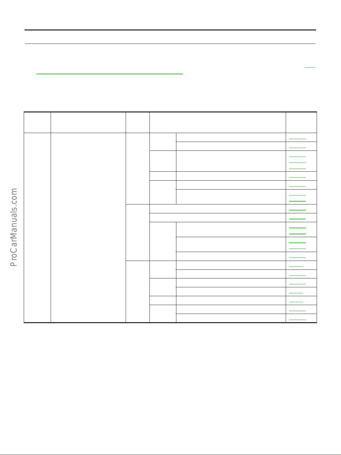
TROUBLE DIAGNOSIS
16. CHECK ECM FUNCTION
1. Substitute another known-good ECM to check ECM function. (ECM may be the cause of a problem, but
this is the rarely the case.)
2. Perform initializatio n of IVIS (NATS) system and registration of IVIS (NATS) ignition key IDs. Refer to EC-
65, "IVIS (Infiniti Vehicle Immobilizer System — NATS)" .
>> GO TO 4.
Symptom Matri x Char t EBS000QF
SYSTEM — BASIC ENGINE CONTROL SYSTEM
Warranty
symptom
code
AA
HARD/NO START/RESTART
(EXCP. HA)
Symptom
Inspec-
tion
order
1.
2.
3.
Diagnostic Item
Fuel
Air Electric throttle control actuator
Ignition Ignition circuit EC-479
Engine
control
Main power supply and ground circuit EC-143
Air conditioner circuit ATC-32
Engine
control
Fuel
Air
Ignition Incorrect ignition timing adjustment EC-82
Engine
control
Fuel pump circuit EC-592
Injector circuit EC-579
Mass air flow sensor circuit EC -154
Engine coolant temperature sensor circu it
Crankshaft position sensor (POS) circuit
ECM
Start signal circuit EC-588
Fuel pressure regulator system EC-48
Evaporative emission system EC-606
Positive crankcase ventilation syste m EC-619
Incorrect idle speed adjustment EC-82
Camshaft position sensor (PHASE) circuit EC-340
Intake valve timing control solenoid valve circuit EC-429
Reference
EC-178
EC-443
EC-447
EC-173
EC-193
EC-331
EC-490
EC-409
EC-416
Page
,
,
,
,
,
Revision: 2004 April 2002 Q45
EC-86

TROUBLE DIAGNOSIS
Warranty
symptom
code
AB ENGINE STALL
Symptom
Inspec-
tion
order
1.
2.
3.
Diagnostic Item
Fuel
Air Electric throttle control actuator
Ignition Ignition circuit EC-479
Engine
control
Main power supply and ground circuit EC-143
Air conditioner circuit ATC-32
Engine
control
Fuel
Air
Ignition Incorrect ignition timing adjustment EC-82
Engine
control
Fuel pump circuit EC-592
Injector circuit EC-579
Mass air flow sensor circuit EC-154
Heated oxygen sensor 1 circuit EC-197
Engine coolant temperature sensor circuit
Throttle position sensor circuit EC-178
Crankshaft position sensor (POS) ci rcu it
Vehicle speed sensor circuit
ECM
Power steering pressure sensor circuit EC-404
Refrigerant pressure sensor circuit EC-598
Fuel pressure regulator system EC-48
Evaporative emission system EC-606
Positive crankcase ventilation syst em EC-619
Incorrect idle speed adjustment EC-82
Intake valve timing control solenoid valve circuit EC-429
Reference
Page
EC-178
EC-443
EC-447
EC-173
EC-193
EC-331
EC-490
EC-400
EC-561
EC-409
EC-416
A
EC
,
,
C
D
,
E
F
,
,
,
G
H
I
J
K
Revision: 2004 April 2002 Q45
EC-87
L
M

TROUBLE DIAGNOSIS
Warranty
symptom
code
AC
HESITATION/SURGING/FLAT
SPOT
Symptom
AD SPARK KNOCK/DETONATION
Inspec-
tion
order
1. Ignition Incorrect ignition timing adjustment EC-82
Fuel
Air Electric throttle control actuator
Ignition Ignition circuit EC-479
2.
Engine
control
Main power supply and ground circuit EC-143
Air conditioner circuit ATC-32
3.
Engine
control
4.
1. Ignition Incorrect ignition timing adjustment EC-82
2.
3.
4.
Fuel
Air Positive crankcase ventilation system EC-619
Ignition Ignition circuit EC-479
Engine
control
Fuel
Air Electric throttle control actuator
Main power supply and ground circuit EC-143
Air conditioner circuit ATC-32
Engine
control
Fuel
Air Positive crankcase ventilation system EC-619
Fuel pump circuit EC-592
Injector circuit EC-579
Mass air flow sensor circuit EC -154
Heated oxygen sensor 1 circuit EC-197
Engine coolant temperature sensor circu it
Throttl e positio n sensor cir cuit EC-178
Knock sensor circuit EC-327
Intake valve timing control solenoid valve circuit EC-429
Vehicle speed sensor circuit
ECM
Park/Neutral position switch circuit EC-555
Accelerator pedal position sensor circuit EC-186
Fuel pressure regulator system EC-48
Evaporative emission system EC-606
Mass air flow sensor circuit EC -154
Accelerator pedal position sensor circuit EC-186
Radiator coolant temperature sensor ci rcu it EC-435
Cooling fan speed control solenoid valve circuit EC-534
Fuel pump circuit EC-592
Injector circuit EC-579
Heated oxygen sensor 1 circuit EC-197
Engine coolant temperature sensor circu it
ECM
Fuel pressure regulator system EC-48
Evaporative emission system EC-606
Diagnostic Item
Reference
Page
EC-178
EC-443
EC-447
EC-173
EC-193
EC-400
EC-561
EC-409
EC-416
EC-178
EC-443
EC-447
EC-173
EC-193
EC-409
EC-416
,
,
,
,
,
,
,
,
,
Revision: 2004 April 2002 Q45
EC-88
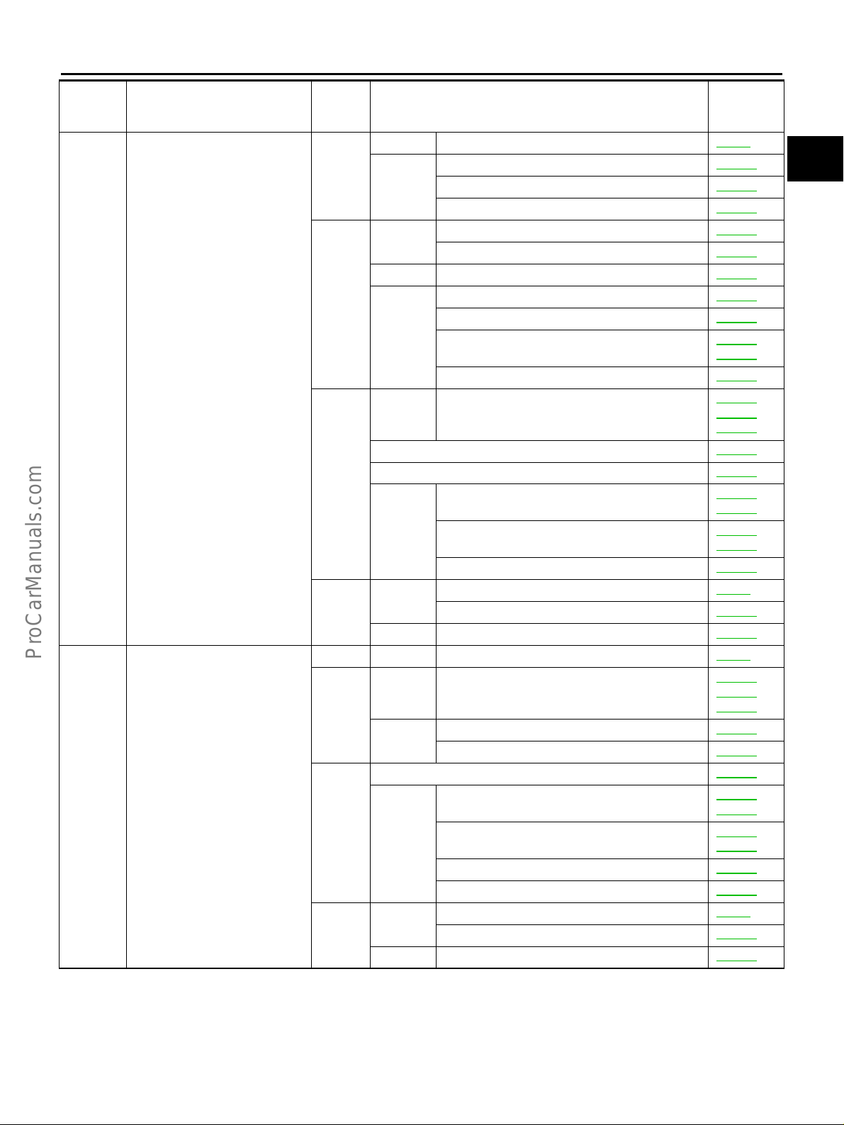
TROUBLE DIAGNOSIS
Warranty
symptom
code
AE
LACK OF POWER/POOR
ACCELERATION
Symptom
AF HIGH IDLE/LOW IDLE
Inspec-
tion
order
Ignition Incorrect ignition timing adjustment EC-82
1.
2.
3.
4.
1. Air Incorrect idle speed adjustment EC-82
2.
3.
4.
Engine
control
Fuel
Ignition Ignition circuit EC-479
Engine
control
Air Electric throttle co n t ro l
Main power supply and ground circuit EC-143
Air conditioner circuit ATC-32
Engine
control
Fuel
Air Positive crankcase ventilation system EC-619
Air Electric throttle control actuator
Engine
control
Air conditioner circuit ATC-32
Engine
control
Fuel
Air Positive crankcase ventilation system EC-619
Accelerator pedal position sensor circuit EC-186
Intake valve timing control solenoid valve circuit EC-429
VIAS control solenoid valve circuit EC-570
Fuel pump circuit EC-592
Injector circuit EC-579
Mass air flow sensor circuit EC-154
Heated oxygen sensor 1 circuit EC-197
Engine coolant temperature sensor circuit
Throttle position sensor circuit EC-178
Vehicle speed sensor circuit
ECM
Park/Neutral position switch circuit EC-555
Fuel pressure regulator system EC-48
Evaporative emission system EC-606
Throttle position sensor circuit EC-178
Accelerator pedal position sensor circuit EC-186
Engine coolant temperature sensor circuit
ECM
Intake valve timing control solenoid valve circuit EC-429
Refrigerant pressure sensor circuit EC-598
Fuel pressure regulator system EC-48
Evaporative emission system EC-606
Diagnostic Item
Reference
Page
EC-173
EC-193
EC-178
EC-443
EC-447
EC-400
EC-561
EC-409
EC-416
EC-178
EC-443
EC-447
EC-173,
EC-193
EC-409
EC-416
A
EC
C
D
,
E
F
,
,
G
,
,
H
I
J
,
,
K
L
M
,
Revision: 2004 April 2002 Q45
EC-89

TROUBLE DIAGNOSIS
Warranty
symptom
code
AG ROUGH IDLE/HUNTING
Symptom
Inspec-
tion
order
1.
2.
3.
4.
Diagnostic Item
Air Incorrect idle speed adjustment EC-82
Ignition Incorrect ignition timing adjustment EC-82
Fuel
Air Electric throttle control actuator
Ignition Ignition circuit EC-479
Engine
control
Main power supply and ground circuit EC-143
Air conditioner circuit ATC-32
Engine
control
Fuel
Air Positive crankcase ventilation system EC-619
Fuel pump circuit EC-592
Injector circuit EC-579
Mass air flow sensor circuit EC -154
Heated oxygen sensor 1 circuit EC-197
Engine coolant temperature sensor circu it
Throttl e positio n sensor cir cuit EC-178
Intake valve timing control solenoid valve circuit EC-429
ECM
Park/Neutral position switch circuit EC-555
Power steering pressure sensor circuit EC-404
Electrical load signal circuit EC-603
Fuel pressure regulator system EC-48
Evaporative emission system EC-606
Reference
Page
EC-178
EC-443
EC-447
EC-173
EC-193
EC-409
EC-416
,
,
,
,
Revision: 2004 April 2002 Q45
EC-90

TROUBLE DIAGNOSIS
Warranty
symptom
code
AH IDLING VIBRATION
Symptom
AJ SLOW /NO RETURN TO IDLE
AK
OVERHEATS/WATER TEMPERATURE HIGH
Inspec-
tion
order
1.
2.
3.
4.
1. Air Incorrect idle speed adjustment EC-82
2.
3.
4.
1.
2. Main power supply and ground circui t EC-143
3.
Air Incorrect idle speed adjustment EC-82
Ignition Incorrect ignition timing adjustment EC-82
Fuel
Air Electric throttle control actuator
Ignition Ignition circuit EC-479
Engine
control
Main power supply and ground circuit EC-143
Air conditioner circuit ATC-32
Engine
control
Fuel
Air Positive crankcase ventilation system EC-619
Air Electric throttle control actuator
Engine
control
Air conditioner circuit ATC-32
Engine
control
Fuel
Air Positive crankcase ventilation system EC-619
Engine
control
Engine
control
Fuel pump circuit EC-592
Injector circuit EC-579
Mass air flow sensor circuit EC-154
Heated oxygen sensor 1 circuit EC-197
Engine coolant temperature sensor circuit
Throttle position sensor circuit EC-178
Intake valve timing control solenoid valve circuit EC-429
ECM
Park/Neutral position switch circuit EC-555
Power steering pressure sensor circuit EC-404
Electrical load signal circuit EC-603
Fuel pressure regulator system EC-48
Evaporative emission system EC-606
Throttle position sensor circuit EC-178
Accelerator pedal position sensor circuit EC-186
Engine coolant temperature sensor circuit
ECM
Intake valve timing control solenoid valve circuit EC-429
Refrigerant pressure sensor circuit EC-598
Fuel pressure regulator system EC-48
Evaporative emission system EC-606
Radiator coolant temperature sensor circuit EC-435
Cooling fan speed control solenoid valve ci rcu it EC-534
ECM
Diagnostic Item
Reference
Page
EC-178
EC-443
EC-447
EC-173
EC-193
EC-409
EC-416
EC-178
EC-443
EC-447
EC-173
EC-193
EC-409
EC-416
EC-409
EC-416
A
EC
C
,
,
D
E
,
F
G
,
H
I
J
,
,
K
L
,
,
,
M
Revision: 2004 April 2002 Q45
EC-91
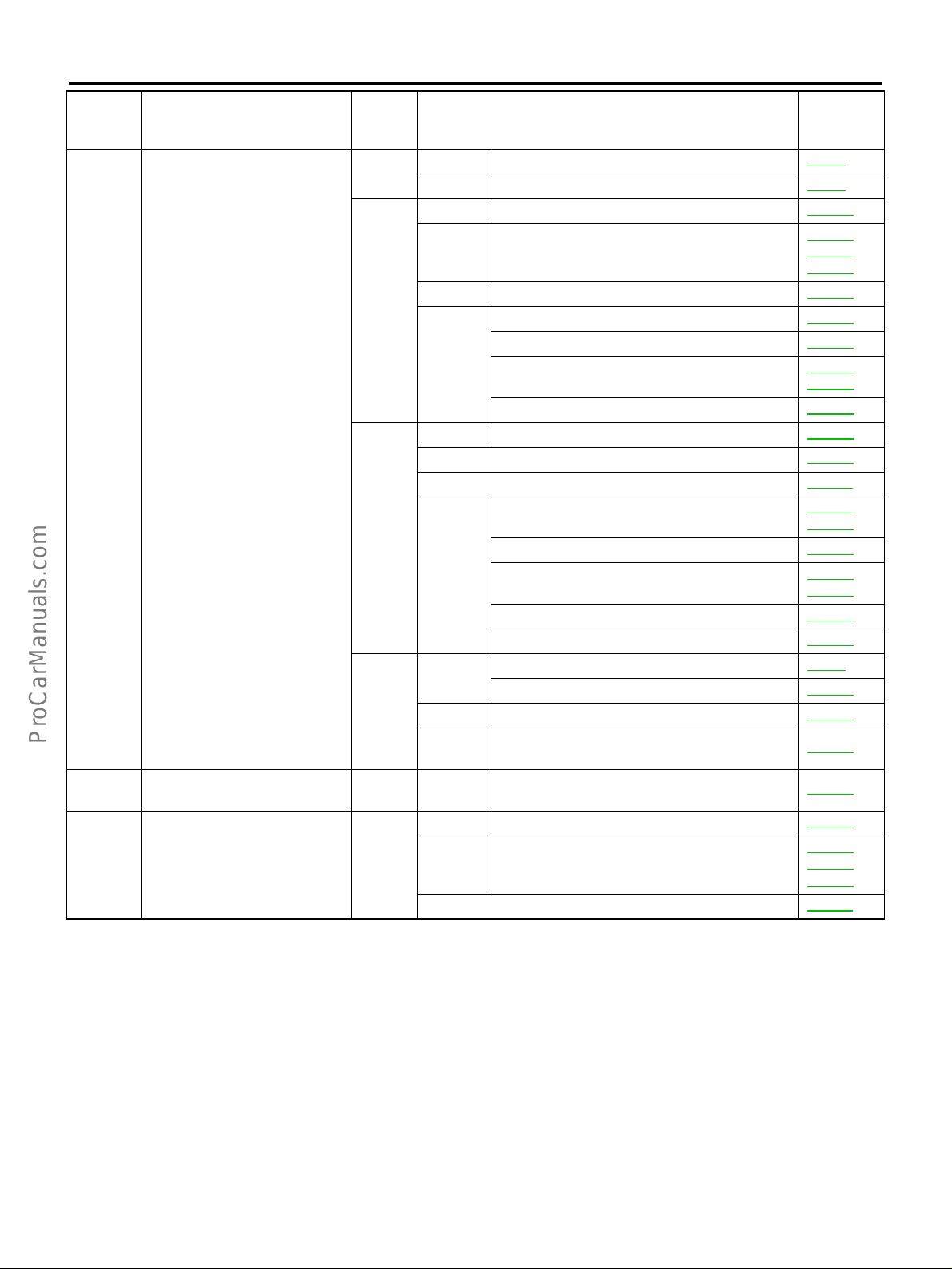
TROUBLE DIAGNOSIS
Warranty
symptom
code
AL
EXCESSIVE FUEL CONSUMPTION
Symptom
AM
HA
EXCESSIVE OIL CONSUMPTION
BATTER Y DEAD (UNDER
CHARGE)
Inspec-
tion
order
1.
2.
3.
4.
1. Air Positive crankcase ventilation system EC-619
2.
Air Incorrect idle speed adjustment EC-82
Ignition Incorrect ignition timing adjustment EC-82
Fuel Injector circuit EC-579
Air Electric throttle control actuator
Ignition Ignition circuit EC-479
Mass air flow sensor circuit EC -154
Engine
control
Fuel Fuel pump circuit EC-592
Main power supply and ground circuit EC-143
Air conditioner circuit ATC-32
Engine
control
Fuel
Air Positive crankcase ventilation system EC-619
Engine
control
Fuel Fuel pump circuit EC-592
Air Electric throttle control actuator
Air conditioner circuit ATC-32
Heated oxygen sensor 1 circuit EC-197
Engine coolant temperature sensor circu it
Throttl e positio n sensor cir cuit EC-178
Vehicle speed sensor circuit
Knock sensor circuit EC-327
ECM
Park/Neutral position switch circuit EC-555
Intake valve timing control solenoid valve circuit EC-429
Fuel pressure regulator system EC-48
Evaporative emission system EC-606
Refrigerant pressure sensor circuit EC-598
Diagnostic Item
Reference
Page
EC-178
EC-443
EC-447
EC-173
EC-193
EC-400
EC-561
EC-409
EC-416
EC-178
EC-443
EC-447
,
,
,
,
,
,
,
Revision: 2004 April 2002 Q45
EC-92

TROUBLE DIAGNOSIS
SYSTEM — ENGINE MECHANICAL & OTHER
Warranty
symptom
code
AA
Symptom
HARD/NO START/
RESTART (EXCP.
HA)
Inspec-
tion
order
1.
2. VDC/TCS/ABS control unit
3. Cranking Starter circuit SC-20
4. Cranking PNP switch AT-82
5.
Cranking
IVIS (Infiniti Vehicle Immobilizer System — N ATS) EC-65 or BL-146
Fuel
Air
Engine
Valve
mechanism
Exhaust
Lubrication
Cooling
Cranking Drive plate EM-67
6.
Engine
Diagnostic Item Reference Page
Battery SC-4
Alternator circuit SC-9
EC-462
or EC-463
or BRC-11
Fuel tank FL-6
Fuel piping FL-2
Valve deposit —
Poor fuel (Heavy weight gasoline, Low octane) —
Air leakage from air duct
(Mass air flow sensor —El ect ri c thr ot tle control
actuator)
Electric throttle control actuator, Throttle wire EM-17, ACC-2
Air leakage from intake manifold/Collector/Gasket EM-17
Cylinder head
Cylinder head gasket
Timing chain EM-45
Camshaft EM-34
Intake valve
Exhaust valve
Exhaust manifold/Tube/Muffler/Gasket EM-22
Three way catalyst EM-22
Oil pan/Oil strainer/Oil pump/Oil filter/Oil gallery EM-25
Oil level (L ow)/Filt h y o il LU-6
Radiator/Hose/Radiator filler cap CO-11
Thermostat CO-23
Water pump CO-21
Water gallery CO-7
Cooling fan CO-17
Coolant level (low)/Contaminated coolant CO-8
Cylinder block
Piston
Piston ring
Connecting rod
Bearing
Crankshaft
EM-15
EM-55
EM-55
, EX-3
, LU-10 , LU-9
EM-67
A
EC
C
D
E
F
G
H
I
J
K
L
M
Revision: 2004 April 2002 Q45
EC-93

TROUBLE DIAGNOSIS
Warranty
symptom
code
AB ENGINE STALL
Symptom
Inspec-
tion
order
1.
2. VDC/TCS/ABS control unit
5.
6. Engine
Cranking
IVIS (Infiniti Vehicle Immobilizer System — NATS) EC-65 or BL-146
Fuel
Air
Engine
Valve
mechanism
Exhaust
Lubrication
Cooling
Battery SC-4
Alternator circuit SC-9
Fuel tank FL-6
Fuel piping FL-2
V apor lock —
Valve deposit —
Poor fuel (Heavy weight gasoline, Low octane) —
Air duct
Air cleaner
Air leakage from air duct
(Mass air flow sensor — Electric throttle control
actuator)
Electric throttle control actuator, Throttle wire EM-17, ACC-2
Air leakage from intake manifold/Collector/Gasket EM-17
Cylinder head
Cylinder head gasket
Timing chain EM-45
Camshaft EM-34
Intake valve
Exhaust valve
Exhaust manifold/Tube/Muffler/Gasket EM-22
Three way catalyst EM-22
Oil pan/Oil strainer/O il pump /Oil filter/Oil gallery EM-25
Oil level (Low)/Filthy oil LU-6
Radiator/Hose/Radiator filler cap CO-11
Thermostat CO-23
Water pump CO-21
Water gallery CO-7
Cooling fan CO-17
Coolant level (low)/Contaminated coolant CO-8
Cylinder block
Piston
Piston ring
Connecting rod
Bearing
Crankshaft
Diagnostic Item Reference Page
EC-462
or EC-463
or BRC-11
EM-15
EM-15
EM-55
EM-55
, EX-3
, LU-10 , LU-9
EM-67
Revision: 2004 April 2002 Q45
EC-94

TROUBLE DIAGNOSIS
Warranty
symptom
code
AC
Symptom
HESITATION/SURGING/FLAT SPOT
Inspec-
tion
order
1. Cranking
2. VDC/TCS/ABS control unit
Fuel
Air
Engine
5.
6. Engine
Valve
mechanism
Exhaust
Lubrication
Cooling
Battery SC-4
Alternator circuit SC-9
Fuel piping FL-2
Valve deposit —
Poor fuel (Heavy weight gasoline, Low octane) —
Air duct
Air cleaner
Air leakage from air duct
(Mass air flow sensor — Electric throttle control
actuator)
Electric throttle control actuator, Throttle wire EM-17, ACC-2
Air leakage from intake manifold/Collector/Gasket EM-17
Cylinder head
Cylinder head gasket
Timing chain EM-45
Camshaft EM-34
Intake valve
Exhaust valve
Exhaust manifold/Tube/Muffler/Gasket EM-22
Three way catalyst EM-22
Oil pan/Oil strainer/Oil pump/Oil filter/Oil gallery EM-25, LU-10 , LU-9
Oil level (L ow)/Filt h y o il LU-6
Radiator/Hose/Radiator filler cap CO-11
Thermostat CO-23
Water pump CO-21
Water gallery CO-7
Cooling fan CO-17
Coolant level (low)/Contaminated coolant CO-8
Cylinder block
Piston
Piston ring
Connecting rod
Bearing
Crankshaft
Diagnostic Item Reference Page
EC-462
or EC-463
or BRC-11
EM-15
EM-15
EM-55
EM-55
, EX-3
EM-67
A
EC
C
D
E
F
G
H
I
J
K
L
M
Revision: 2004 April 2002 Q45
EC-95

TROUBLE DIAGNOSIS
Warranty
symptom
code
AD
Symptom
SPARK KNOCK/DETONATION
Inspec-
tion
order
2. VDC/TCS/ABS control unit
Fuel piping FL-2
Fuel
Air
Engine
Valve
5.
6. Engine
mechanism
Exhaust
Lubrication
Cooling
Valve deposit —
Poor fuel (Heavy weight gasoline, Low octane) —
Air leakage from air duct
(Mass air flow sensor — Electric throttle control
actuator)
Electric throttle control actuator, Throttle wire EM-17, ACC-2
Air leakage from intake manifold/Collector/Gasket EM-17
Cylinder head
Cylinder head gasket
Timing chain EM-45
Camshaft EM-34
Intake valve
Exhaust valve
Exhaust manifold/Tube/Muffler/Gasket EM-22
Three way catalyst EM-22
Oil pan/Oil strainer/O il pump /Oil filter/Oil gallery EM-25, LU-10 , LU-9
Oil level (Low)/Filthy oil LU-6
Radiator/Hose/Radiator filler cap CO-11
Thermostat CO-23
Water pump CO-21
Water gallery CO-7
Cooling fan CO-17
Coolant level (low)/Contaminated coolant CO-8
Cylinder block
Piston
Piston ring
Connecting rod
Bearing
Crankshaft
Diagnostic Item Reference Page
EC-462
or EC-463
or BRC-11
EM-15
EM-55
EM-55
, EX-3
EM-67
Revision: 2004 April 2002 Q45
EC-96

TROUBLE DIAGNOSIS
Warranty
symptom
code
AE
Symptom
LACK OF POWER/
POOR ACCELERATION
AF
HIGH IDLE/LOW
IDLE
Inspec-
tion
order
1. Cranking
2. VDC/TCS/ABS control unit
Fuel
Air
Engine
5.
6. Engine
5.
Valve
mechanism
Exhaust
Lubrication
Cooling
Air
Exhaust
Battery SC-4
Alternator circuit SC-9
Fuel piping FL-2
Valve deposit —
Poor fuel (Heavy weight gasoline, Low octane) —
Air duct
Air cleaner
Air leakage from air duct
(Mass air flow sensor — Electric throttle control
actuator)
Electric throttle control actuator, Throttle wire EM-17, ACC-2
Air leakage from intake manifold/Collector/Gasket EM-17
Cylinder head
Cylinder head gasket
Timing chain EM-45
Camshaft EM-34
Intake valve
Exhaust valve
Exhaust manifold/Tube/Muffler/Gasket EM-22
Three way catalyst EM-22
Oil pan/Oil strainer/Oil pump/Oil filter/Oil gallery EM-25, LU-10 , LU-9
Oil level (L ow)/Filt h y o il LU-6
Radiator/Hose/Radiator filler cap CO-11
Thermostat CO-23
Water pump CO-21
Water gallery CO-7
Cooling fan CO-17
Coolant level (low)/Contaminated coolant CO-8
Cylinder block
Piston
Piston ring
Connecting rod
Bearing
Crankshaft
Air leakage from air duct
(Mass air flow sensor — Electric throttle control
actuator)
Electric throttle control actuator, Throttle wire EM-17, ACC-2
Air leakage from intake manifold/Collector/Gasket EM-17
Exhaust manifold/Tube/Muffler/Gasket EM-22
Three way catalyst EM-22
Diagnostic Item Reference Page
EC-462
or EC-463
or BRC-11
EM-15
EM-15
EM-55
EM-55
, EX-3
EM-67
EM-15
, EX-3
A
EC
C
D
E
F
G
H
I
J
K
L
M
Revision: 2004 April 2002 Q45
EC-97

TROUBLE DIAGNOSIS
Warranty
symptom
code
AG
Symptom
ROUGH IDLE/HUNTING
Inspec-
tion
order
1. Cranking
Fuel
Air
Engine
5.
6. Engine
Valve
mechanism
Exhaust
Lubrication
Cooling
Diagnostic Item Reference Page
Battery SC-4
Alternator circuit SC-9
Fuel piping FL-2
Valve deposit —
Poor fuel (Heavy weight gasoline, Low octane) —
Air duct
Air cleaner
Air leakage from air duct
(Mass air flow sensor — Electric throttle control
actuator)
Electric throttle control actuator, Throttle wire EM-17, ACC-2
Air leakage from intake manifold/Collector/Gasket EM-17
Cylinder head
Cylinder head gasket
Timing chain EM-45
Camshaft EM-34
Intake valve
Exhaust valve
Exhaust manifold/Tube/Muffler/Gasket EM-22
Three way catalyst EM-22
Oil pan/Oil strainer/O il pump /Oil filter/Oil gallery EM-25, LU-10 , LU-9
Oil level (Low)/Filthy oil LU-6
Radiator/Hose/Radiator filler cap CO-11
Thermostat CO-23
Water pump CO-21
Water gallery CO-7
Cooling fan CO-17
Coolant level (low)/Contaminated coolant CO-8
Cylinder block
Piston
Piston ring
Connecting rod
Bearing
Crankshaft
EM-15
EM-15
EM-55
EM-55
, EX-3
EM-67
Revision: 2004 April 2002 Q45
EC-98

TROUBLE DIAGNOSIS
Warranty
symptom
code
AH IDLING VIBRATION
Symptom
AJ
HIGH IDLE/LOW
IDLE
Inspec-
tion
order
1. Cranking
Fuel
Air
Engine
5.
Valve
mechanism
Lubrication
Cooling
6. Engine
Air
5.
Exhaust
Cooling
Diagnostic Item Reference Page
Battery SC-4
Alternator circuit SC-9
Fuel piping FL-2
Valve deposit —
Poor fuel (Heavy weight gasoline, Low octane) —
Air duct
Air cleaner
Air leakage from air duct
(Mass air flow sensor — Electric throttle control
actuator)
Electric throttle control actuator, Throttle wire EM-17, ACC-2
Air leakage from intake manifold/Collector/Gasket EM-17
Cylinder head
Cylinder head gasket
Timing chain EM-45
Camshaft EM-34
Intake valve
Exhaust valve
Oil pan/Oil strainer/Oil pump/Oil filter/Oil gallery EM-25
Oil level (L ow)/Filt h y o il LU-6
Radiator/Hose/Radiator filler cap CO-11
Thermostat CO-23
Water pump CO-21
Water gallery CO-7
Cooling fan CO-17
Coolant level (low)/Contaminated coolant CO-8
Cylinder block
Piston
Piston ring
Connecting rod
Bearing
Crankshaft
Air leakage from air duct
(Mass air flow sensor — Electric throttle control
actuator)
Electric throttle control actuator, Throttle wire EM-17, ACC-2
Air leakage from intake manifold/Collector/Gasket EM-17
Exhaust manifold/Tube/Muffler/Gasket EM-22
Three way catalyst EM-22
Thermostat CO-23
Cooling fan CO-17
EM-15
EM-15
EM-55
EM-55
, LU-10 , LU-9
EM-67
EM-15
, EX-3
A
EC
C
D
E
F
G
H
I
J
K
L
M
Revision: 2004 April 2002 Q45
EC-99

TROUBLE DIAGNOSIS
Warranty
symptom
code
AK
AL
Symptom
OVERHEATS/
WATER TEMPERATURE HIGH
EXCESSIVE FUEL
CONSUMPTION
Inspec-
tion
order
Engine Cylinder hea d gasket EM-55
4.
1. Cranking
5.
6. Engine
Cooling
Fuel
Air
Engine
Valve
mechanism
Lubrication
Cooling
Diagnostic Item Reference Page
Radiator/Hose/Radiator filler cap CO-11
Thermostat CO-23
Water pump CO-21
Water gallery CO-7
Cooling fan CO-17
Coolant level (low)/Contaminated coolant CO-8
Battery SC-4
Alternator circuit SC-9
Fuel piping FL-2
Valve deposit —
Poor fuel (Heavy weight gasoline, Low octane) —
Air duct
Air cleaner
Air leakage from air duct
(Mass air flow sensor — Electric throttle control
actuator)
Electric throttle control actuator, Throttle wire EM-17, ACC-2
Air leakage from intake manifold/Collector/Gasket EM-17
Cylinder head
Cylinder head gasket
Timing chain EM-45
Camshaft EM-34
Intake valve
Exhaust valve
Oil pan/Oil strainer/O il pump /Oil filter/Oil gallery EM-25
Oil level (Low)/Filthy oil LU-6
Radiator/Hose/Radiator filler cap CO-11
Thermostat CO-23
Water pump CO-21
Water gallery CO-7
Cooling fan CO-17
Coolant level (low)/Contaminated coolant CO-8
Cylinder block
Piston
Piston ring
Connecting rod
Bearing
Crankshaft
EM-15
EM-15
EM-55
EM-55
, LU-10 , LU-9
EM-67
Revision: 2004 April 2002 Q45
EC-100
 Loading...