

Page 1

For your safety, read carefully and keep in this vehicle.
Q45
2001 OWNER’S MANUAL
Page 2

FOREWORD
Your INFINITI represents a new way of thinking
about vehicle design. It integrates advanced engineering and superior craftsmanship with a simple,
refined aesthetic sensitivity associated with traditional Japanese culture.
The result is a different notion of luxury and beauty.
The car itself is important, but so also is the sense
of harmony that the vehicle evokes in its driver, and
the sense of satisfaction you feel with the INFINITI
— from the way it looks and drives to the high level
of dealer service.
To ensure that you enjoy your INFINITI to the
fullest, we encourage you to read this Owner’s
Manual immediately. It explains all of the features,
controls and performance characteristics of your
INFINITI; it also provides important instructions and
safety information.
A separate Warranty Information Booklet is
to be found in your Owner’s literature portfolio. Always carry it with you when you take
your INFINITI to an authorized dealer. The
portfolio contents provide complete information about all warranties covering this
vehicle, the periodic maintenance required
to keep the warranties in effect as well as
the INFINITI Roadside Assistance program.
Additionally, a separate Customer Care and
Lemon Law Information Booklet will explain
how to resolve any concerns you may have
with your vehicle, as well as clarify your
rights under your state’s lemon law.
INFINITI is dedicated to providing a satisfying
ownership experience for as long as you own your
car. Should you have any questions regarding your
INFINITI or your INFINITI dealer, please contact our
Consumer Affairs department at 1-800-662-6200.
In Hawaii 1-808-836-0848 (Oahu number). In
Canada 1-800-387-0122. Thank you.
READ FIRST — THEN DRIVE
SAFELY
Before driving your vehicle please read your
Owner’s Manual carefully. This will ensure
familiarity with controls and maintenance requirements, assisting you in the safe operation of your vehicle.
WARNING
IMPORTANT SAFETY
INFORMATION
REMINDERS FOR SAFETY!
Follow these important driving rules
to help ensure a safe and comfortable trip for you and your passengers!
O NEVER drive under the influence
of alcohol or drugs.
O ALWAYS observe posted speed
limits and never drive too fast for
conditions.
O ALWAYS use your seat belts and
appropriate child restraint systems. Pre-teen children should be
seated in the rear seat.
O ALWAYS provide information
about the proper use of vehicle
Page 3

safety features to all occupants of
the vehicle.
O ALWAYS review this Owner’s
Manual for important safety information.
MODIFICATION OF YOUR
VEHICLE
This vehicle should not be modified.
Modification could affect its performance, safety or durability, and may
even violate governmental regulations. In addition, damage or performance problems resulting from
modification may not be covered
under INFINITI warranties.
WHEN READING THE
MANUAL
This manual includes information for all
options available on this model. Therefore, you may find some information
that does not apply to your vehicle.
All information, specifications and illustrations in this manual are those in effect at the
time of printing. INFINITI reserves the right to
change specifications or design at any time
without notice.
IMPORTANT INFORMATION
ABOUT THIS MANUAL
You will see various symbols in this manual.
They are used in the following ways:
WARNING
This is used to indicate the presence
of a hazard that could cause death or
serious personal injury. To avoid or
reduce the risk, the procedures must
be followed precisely.
CAUTION
This is used to indicate the presence
of a hazard that could cause minor or
moderate personal injury or damage
to your vehicle. To avoid or reduce
the risk, the procedures must be followed carefully.
Page 4

SII0151
If you see this symbol, it means Do not do
this or Do not let this happen.
© 2000 NISSAN MOTOR CO., LTD.
TOKYO, JAPAN
All rights reserved. No part of this Owner’s Manual may be
reproduced or stored in a retrieval system, or transmitted
in any form, or by any means, electronic, mechanical,
photocopying, recording or otherwise, without the prior
written permission of Nissan Motor Co., Ltd.
CALIFORNIA PROPOSITION 65
WARNING
WARNING
Engine Exhaust, some of its constituents, and certain vehiclecomponents
contain or emit chemicals known to
State of California to cause cancer
and birth defects or other reproductive harm.
Page 5

TABLE OF CONTENTS
SEATS, RESTRAINTS AND SUPPLEMENTAL AIR BAG SYSTEMS ................... 1-1
INSTRUMENTS AND CONTROLS .......................................................... 2-1
PRE-DRIVING CHECKS AND ADJUSTMENTS............................................ 3-1
HEATER, AIR CONDITIONER AND AUDIO SYSTEMS .................................. 4-1
STARTING AND DRIVING................................................................... 5-1
IN CASE OF EMERGENCY .................................................................. 6-1
APPEARANCE AND CARE................................................................... 7-1
DO-IT-YOURSELF ............................................................................ 8-1
MAINTENANCE ............................................................................... 9-1
TECHNICAL AND CONSUMER INFORMATION ......................................... 10-1
INDEX ........................................................................................ 11-1
Page 6

Page 7

1 SEATS, RESTRAINTS AND SUPPLEMENTAL AIR BAG SYSTEMS
Seats............................................................ 1-2
Front power seat adjustment ................. 1-2
Head restraint adjustment ...................... 1-4
Active head restraint (Front seats) ........ 1-5
Supplemental restraint system.................... 1-6
Precautions on supplemental restraint
system.................................................... 1-6
Supplemental air bag warning labels... 1-19
Supplemental air bag warning light..... 1-20
Seat bel ts .................................................. 1-21
Precautions on seat belt usage ........... 1-21
Child safety........................................... 1-24
Pregnant women .................................. 1-26
Injured persons .................................... 1-26
Three-point type seat belt with
retractor................................................ 1-26
Seat bel t extenders .............................. 1-30
Seat bel t maintenance ......................... 1-30
Child restraints .......................................... 1-30
Precautions on child restraints ............ 1-30
Installation on rear seat outboard or center
positions............................................... 1-33
Top tether strap child restraint ............ 1-38
Installation on front passenger seat.... 1-39
Page 8
SEATS, RESTRAINTS AND SUPPLEMENTAL AIR BAG SYSTEMS
SEATS
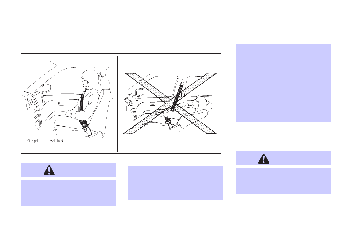
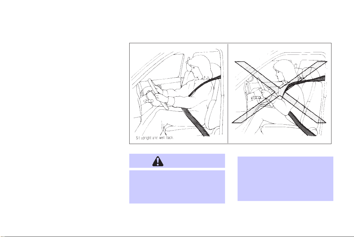
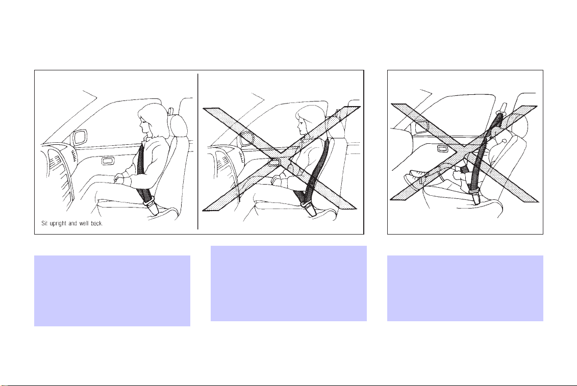
WARNING
O
Do not ride in a moving vehicle
when the seatback is reclined.
This can be dangerous. The
1-2
SIR0091
shoulder belt will not be against
your body. In an accident you
could bethrown into it and receive
neck or other serious inju-
ries. You could also slide under
the lap belt and receive serious
internal injuries.
O
For most effective protection
when the vehicle is in motion, the
seat should be upright. Always sit
well back in the seat and adjust
the seat belt properly. See “Precautions on seat belt usage” later
in this section.
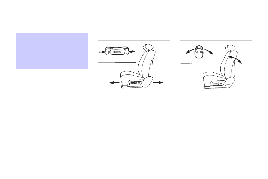
FRONT POWER SEAT ADJUSTMENT
WARNING
O
Do not adjust the driver’s seat
while driving so full attention may
be given to vehicle operation.
Page 9
SEATS, RESTRAINTS AND SUPPLEMENTAL AIR BAG SYSTEMS
O
Do not leave children unattended
inside the vehicle. They could
unknowingly activate switches or
controls. Unattended children
could become involved in serious
accidents.
Operating tips
O The motor has an auto-reset overload
protection circuit. If the motor stops during
operation, wait 30 seconds, then reactivate
the switch.
O Do not operate the power seat for a long
period of time when the engine is off. This
will discharge the battery.
Forward and backward
SIP0102 SIP0103
Moving the switch forward or backward will
slide the seat forward or backward to the
desired position.
Reclining
Move the recline switch backward until the
desired angle is obtained. To bring the seatback forward again, move the switch forward
and move your body forward. The seatback
will move forward.
1-3
Page 10
SEATS, RESTRAINTS AND SUPPLEMENTAL AIR BAG SYSTEMS
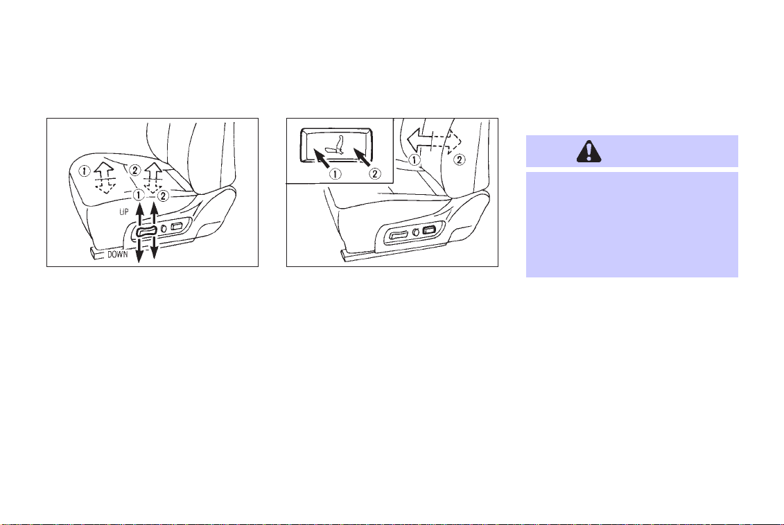
Seat lifter (Driver’s seat)
SIP0104 SIP0105
Push the front or rear end of the switch up or
down to adjust the angle and height of the seat
cushion.
1-4
Lumbar support (Driver’s seat)
Push either side of the switch to adjust the
seat lumbar area.
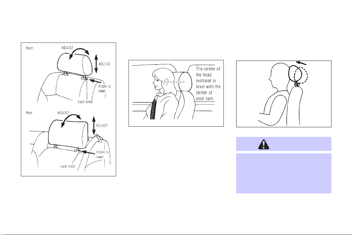
HEAD RESTRAINT ADJUSTMENT
WARNING
Head restraints should be adjusted
properly as they may provide significant protection against injury in an
accident. Donot remove them. Check
the adjustment after someone else
uses the seat.
Page 11
SEATS, RESTRAINTS AND SUPPLEMENTAL AIR BAG SYSTEMS
SIR0099
To raise the head restraint, simply pull it up.
To lower, push the lock knob and push the
head restraint down.
To adjust the head restraint forward and
backward, push it in the direction required.
SIR0144
Adjust the head restraints so the center is level
with the center of your ears.
ACTIVE HEAD RESTRAINT
(Front seats)
WARNING
O
Always adjust the head restraints
properly as specified in the previous section. Failure to do so can
reduce the effectiveness ofthe active head restraint.
SIR0113
1-5
Page 12

SEATS, RESTRAINTS AND SUPPLEMENTAL AIR BAG SYSTEMS
O
Active head restraints are designed to supplement other safety
systems. Always wear seat belts.
No system can prevent all injuries
in any accident.
O
Do not attach anything to the head
restraint stalks. Doing so could
impair active head restraint function.
The head restraint moves outward and forward
utilizing the force that the seatback receives
from the occupant in a rear-end collision. The
movement of the head restraint helps support
the occupant’s head by reducing its backward
movement and helping absorb some of the
forces that may lead to whiplash type injuries.
Active head restraints are effective for collisions at low to medium speeds in which it is
said that whiplash injury occurs most.
1-6
Active head restraints operate only in certain
rear-end collisions. After the collision, the
head restraints return to their original positions.
Properly adjust the active head restraints as
described in the previous section.
SUPPLEMENTAL
RESTRAINT SYSTEM
PRECAUTIONS ON SUPPLEMENTAL RESTRAINT SYSTEM
This Supplemental Restraint System (SRS)
section contains important information concerning the driver and passenger front impact
supplemental air bags, front seat side-impact
supplemental air bags and pre-tensioner seat
belt.
Front impact supplemental air bag system: This system can help cushion the
impact force to the face and chest of the driver
and front passenger in certain frontal collisions.
Side-impact supplemental air bag system: This system can help cushion the
impact force to the head and chest area of the
driver and front passenger in certain side
impact collisions. The front seat side-impact
supplemental air bag is designed to inflate on
the side where the vehicle is impacted.
These supplemental restraint systems are designed to supplement the crash protection
provided by the driver and front passenger
seat belts and are not a substitute for them.
Seat belts should always be correctly worn
and the driver and front passenger seated a
suitable distance away from the steering
wheel, instrument panel and front door finishers. (See “Seat belts” later in this section for
instructions and precautions on seat belt
usage.)
After turning the ignition key to the ON
position, the supplemental air bag
warning light illuminates. The supplemental air bag warninglight will turn off
Page 13
SEATS, RESTRAINTS AND SUPPLEMENTAL AIR BAG SYSTEMS
after about 7 seconds if the system is operational.
SIR0092
WARNING
O
The supplemental front air bags
ordinarily will not inflate in the
event of a side impact, rear impact, roll over, or lower severity
frontal collision. Always wear
your seat belts to help reduce the
risk or severity of injury in various
kinds of accidents.
O
The seat belts and the supple-
1-7
Page 14

SEATS, RESTRAINTS AND SUPPLEMENTAL AIR BAG SYSTEMS
mental front air bags are most
effective when you are sitting
well back and upright in the seat.
Front air bags inflate with great
force. If you are unrestrained,
leaning forward, sitting sideways
or out of position in any way, you
are at greater risk of injury or
death in a crash and may also
receive serious or fatal injuries
from the supplemental front air
bag if you are up against it when
it inflates. Always sit back
against the seatback and as far
away as practical from the steering wheel or instrument panel.
Always use the seat belts.
O
Keep hands on the outside of the
steering wheel. Placing them inside the steering wheel rim could
increase the risk that they are
1-8
injured when the supplemental
front air bag inflates.
Page 15

SEATS, RESTRAINTS AND SUPPLEMENTAL AIR BAG SYSTEMS
SIR0093 SIR0006
1-9
Page 16
SEATS, RESTRAINTS AND SUPPLEMENTAL AIR BAG SYSTEMS
SIR0007 SIR0008 SIR0009
1-10
Page 17
SEATS, RESTRAINTS AND SUPPLEMENTAL AIR BAG SYSTEMS
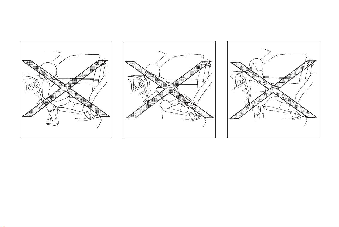
WARNING
O
Never let children ride unrestrained or extend their hands or
face out of the window. Do not attempt to hold them in your lap or
arms. Some examples of dangerous riding positions are shown in
the previous illustrations.
O
Children may be severely injured
or killed when the supplemental
SIR0010 SIR0011
front air bag or supplemental side
air bag inflates if they are not
properly restrained.
O
Also never install a rear facing
child restraint in the front seat.
An inflating supplemental front
air bag could seriously injure or
kill your child. See “Child re-
1-11
Page 18
SEATS, RESTRAINTS AND SUPPLEMENTAL AIR BAG SYSTEMS
straints” later in this section for
details.
SIR0094
SIR0121
1-12
SIR0059
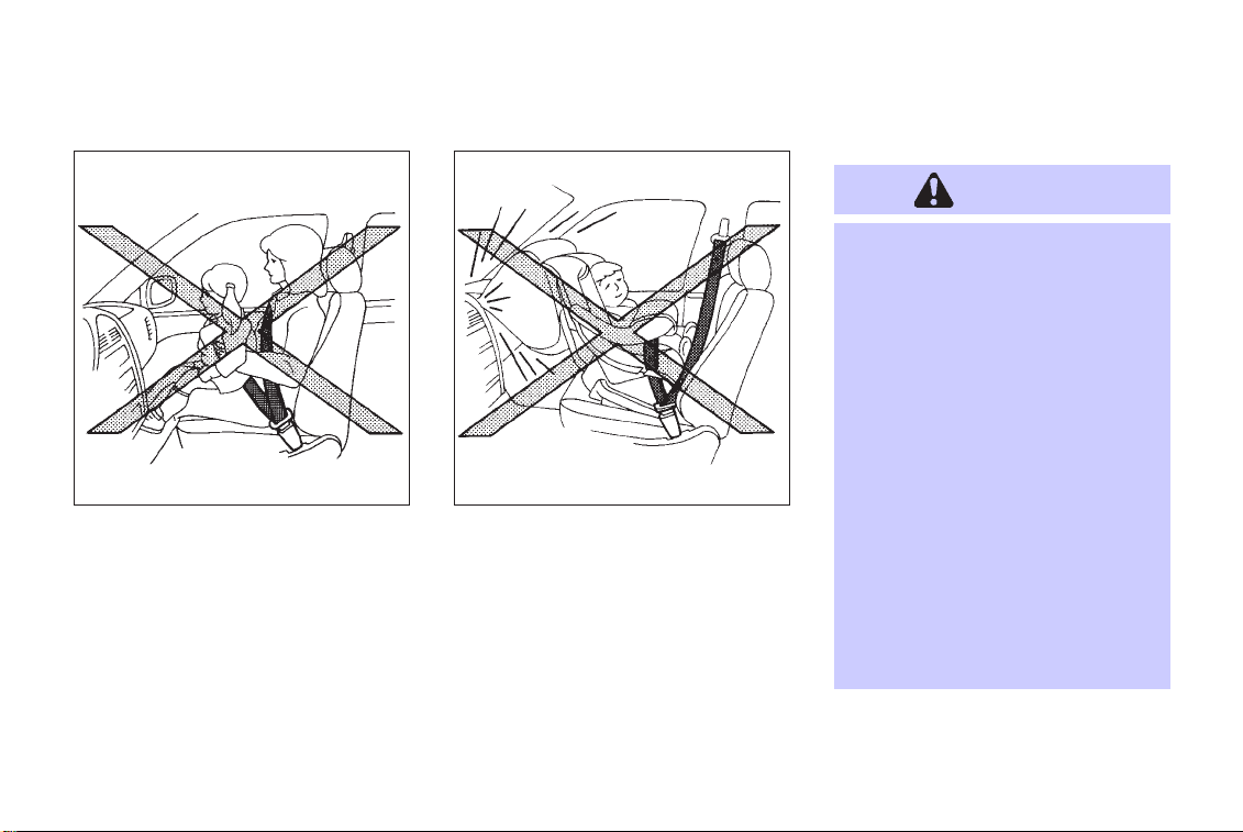
WARNING
Supplemental side air bag:
O
The supplemental side air bag
ordinarily will not inflate in the
SIR0122
Page 19

SEATS, RESTRAINTS AND SUPPLEMENTAL AIR BAG SYSTEMS
event of a frontal impact, rear impact or lower severity side collision. Always wear your seat belts
to help reduce the risk or severity
of injury in various kinds of accidents.
O
The seat belts and the supplemental side air bag are most
effective when you are sitting
well back and upright in the seat.
The side air bag inflates with
great force. Do not allow anyone
to place their hand, leg or face
near the side air bag on the side
of the seatback of the front seat.
Do not allow anyone sitting in the
front seat to extend their hand out
of the window or lean against the
door. Some examples of dangerous riding positions are shown in
the previous illustrations.
O
When sitting in the rear seat, do
not hold onto the seatback of the
front seat. If the supplemental
side air bag inflates, the occupant
may be seriously injured. Be especially careful with children,
who should always be properly
restrained.
O
Do not use seat covers on the
front seatbacks. They may interfere with supplemental side air
bag inflation.
1-13
Page 20
SEATS, RESTRAINTS AND SUPPLEMENTAL AIR BAG SYSTEMS
inflate in higher severity frontal collisions,
although they may inflate if the forces in
another type of collision are similar to those of
a higher severity frontal impact. They may not
inflate in certain frontal collisions. Vehicle
damage (or lack of it) is not always an
indication of proper supplemental air bag
operation.
When the supplemental front air bag inflates,
a fairly loud noise may be heard, followed by
release of smoke. This smoke is not harmful
and does not indicate a fire, but care should
be taken not to inhale it, as it may cause
irritation and choking. Those with a history of
a breathing condition should get fresh air
promptly.
Supplemental front air bags along with the use
of seat belts, help to cushion the impact force
on the face and chest of the front occupants.
They can help save lives and reduce serious
injuries. However, an inflating front air bag
may cause facial abrasions or other injuries.
Front air bags do not provide restraint to the
lower body.
Supplemental front air bag system
The driver supplemental air bag is located in
the center of the steering wheel; the front
passenger supplemental air bag is mounted in
the dashboard above the glove box. These
systems are designed to meet optional certi-
SIR0095B
fication requirements under U.S. regulations.
They are also permitted in Canada. The
optional certification allows front air bags to
be designed to inflate somewhat less forcefully than previously. However, all of the
information, cautions and warnings in
this manual still apply and must be
followed. The front air bags are designed to
1-14
Page 21

SEATS, RESTRAINTS AND SUPPLEMENTAL AIR BAG SYSTEMS
The seat belts should be correctly worn and
the driver and passenger seated upright as far
as practical away from the steering wheel or
dash board. Since the supplemental front air
bags inflate quickly in order to help protect the
front occupants, the force of the front air bag
inflating can increase the risk of injury if the
occupant is too close to or is against the air
bag module during inflation. The air bag will
deflate quickly after the collision is over.
After turning the ignition key to the ON
position, the supplemental air bag
warning light illuminates. The air bag
warning light will turn off after about 7
seconds if the system is operational.
WARNING
O
Do not place any objects on the
steering wheel pad or on the instrument panel.Also, do notplace
any objects between any occupant
and the steering wheel or instrument panel. Such objects may
become dangerous projectiles
and cause injury if the supplemental front air bag inflates.
O
Right after inflation, several air
bag system components will be
hot. Do not touch them; you may
severely burn yourself.
O
No unauthorized changes should
be made to any components or
wiring of the supplemental front
air bag system. This is to prevent
accidental inflation of the air bag
or damage to the air bag system.
O
Do not make unauthorized
changes to your vehicle’s electrical system, suspension system or
front end structure. This could
affect proper operation of the
supplemental front air bag system.
O
Tampering with the supplemental
front air bag system may result in
serious personal injury. Tampering includes changes to the steering wheel and the instrument
panel assembly by placing material over the steering wheel pad
and above the instrument panel,
or by installing additional trim
material around the air bag system.
O
Work around and on the supplemental front air bag system
should be done by an authorized
INFINITI dealer. Installation of
electrical equipment should also
be done by an authorized INFINITI
dealer. The yellow Supplemental
1-15
Page 22
SEATS, RESTRAINTS AND SUPPLEMENTAL AIR BAG SYSTEMS
Restraint System (SRS) wiring
should not be modified or disconnected. Unauthorized electrical
test equipment and probing devices should not be used on the
air bag system.
When selling your vehicle, we request that you
inform the buyer about the supplemental front
air bag system and guide the buyer to the
appropriate sections in this Owner’s Manual.
1-16
Supplemental side air bag system
SIR0129
The supplemental side air bags are located in
the outside of the seatback of the front seats.
The supplemental side air bag (on the driver
or front passenger seat) is designed to inflate
in higher severity side collisions, although it
may inflate if the forces in another type of
collision are similar to those of a higher
severity side impact. It is designed to inflate
on the side where the vehicle is impacted. It
may not inflate in certain side collisions.
Vehicle damage (or lack of it) is not always an
indication of proper supplemental side air bag
operation.
When the supplemental side air bag inflates, a
fairly loud noise may be heard, followed by
release of smoke. This smoke is not harmful
and does not indicate a fire, but care should
be taken not to inhale it, as it may cause
irritation and choking. Those with a history of
a breathing condition should get fresh air
promptly.
Supplemental side air bags along with the use
of seat belts, help to cushion the impact force
on the head and chest of the front occupants.
They can help save lives and reduce serious
injuries. However, an inflating side air bag
may cause abrasions or other injuries.
The seat belts should be correctly worn and
the driver and passenger seated upright as far
as practical away from the side air bag. Since
the side air bags inflate quickly in order to
help protect the front occupants, the force of
the side air bag inflating can increase the risk
of injury if the occupant is too close to or is
against the side air bag module during infla-
Page 23

SEATS, RESTRAINTS AND SUPPLEMENTAL AIR BAG SYSTEMS
tion. The side air bag will deflate quickly after
the collision is over.
After turning the ignition key to the ON
position, the supplemental air bag
warning light illuminates. The air bag
warning light will turn off after about 7
seconds if the system is operational.
WARNING
O
Do not place any objects near the
seatback of the front seats. Also,
do not place any objects (an umbrella, bag, etc.) between the
front door finisher and the front
seat. Such objects may become
dangerous projectiles and cause
injury if the side air bag inflates.
O
Right after inflation, several side
air bag system components will
be hot. Do not touch them; you
may severely burn yourself.
O
No unauthorized changes should
be made to any components or
wiring of this side air bag system.
This is to prevent accidental inflation of the side air bag or
damage to the side air bag system.
O
Do not make unauthorized
changes to your vehicle’s electrical system, suspension system or
side panel. This could affect
proper operation of the supplemental side air bag system.
O
Tampering with the supplemental
system may result in serious personal injury. Tampering includes
changes to the front seats assembly by placing material near the
seatback of the front seat, or by
installing additional trim material, such as seat covers, around
the side air bag system.
O
Work around and on the side air
bag system should be done by an
authorized INFINITI dealer. Installation of electrical equipment
should also be done by an authorized INFINITI dealer. The SRS
wiring harnesses* should not be
modified or disconnected. Unauthorized electrical test equipment
and probing devices should not
be used on the side air bag system.
* The SRS wiring harnesses are
covered with yellow insulation either just before the harness connectors or over the complete harness for easy identification.
1-17
Page 24

SEATS, RESTRAINTS AND SUPPLEMENTAL AIR BAG SYSTEMS
When selling your vehicle, we request that you
inform the buyer about the side air bag system
and guide the buyer to the appropriate sections in this Owner’s Manual.
Pre-tensioner seat belt system
(For front seats)
WARNING
O
The pre-tensionerseat belt cannot
be reused after activation. It must
be replaced together with the retractor as a unit.
O
If the vehicle becomes involved in
a frontal collision but the pretensioner is not activated, be sure
to have the pre-tensioner system
checked and, if necessary, replaced by your INFINITI dealer.
O
No unauthorized changes should
1-18
be made to any components or
wiring of the pre-tensioner seat
belt system. This is to prevent
accidental retraction of the pretensioner seat belt or damage to
the pre-tensioner seat belt operation. Tampering with the pretensioner seat belt system may
result in serious personal injury.
O
Work around and on the pretensioner system should be done by
an authorized INFINITI dealer. Installation of electrical equipment
should also be done by an authorized INFINITI dealer. Unauthorized electrical test equipment
and probing devices should not
be used on the pre-tensioner seat
belt system.
O
If you need to dispose of the
pre-tensioner or scrap the vehicle, contact an authorized
INFINITI dealer. Correct pretensioner disposal procedures
are set forth in the appropriate
INFINITI Service Manual. Incorrect disposal procedures could
cause personal injury.
The front seat pre-tensioner seat belt system
activates in conjunction with the supplemental
front air bag. Working with the seat belt
retractor, it helps tighten the seat belt the
instant the vehicle becomes involved in certain types of collisions, thereby restraining
seat occupants.
The pre-tensioner is encased with the seat
belt’s retractor. These seat belts are used the
same as conventional seat belts.
When the pre-tensioner seat belt activates,
smoke is released and a loud noise may be
Page 25
SEATS, RESTRAINTS AND SUPPLEMENTAL AIR BAG SYSTEMS
heard. The smoke is not harmful, but care
should be taken not to inhale it as it may
cause irritation and choking.
If any abnormality occurs in the pre-tensioner
system, the seat belt warning light
flash intermittently after the ignition key is
turned to the ON or START position. In this
case, the pre-tensioner seat belt will not
function properly.
When selling your vehicle, we request that you
inform the buyer about the pre-tensioner seat
belt system and guide the buyer to the
appropriate sections in this Owner’s Manual.
will
SUPPLEMENTAL AIR BAG
WARNING LABELS
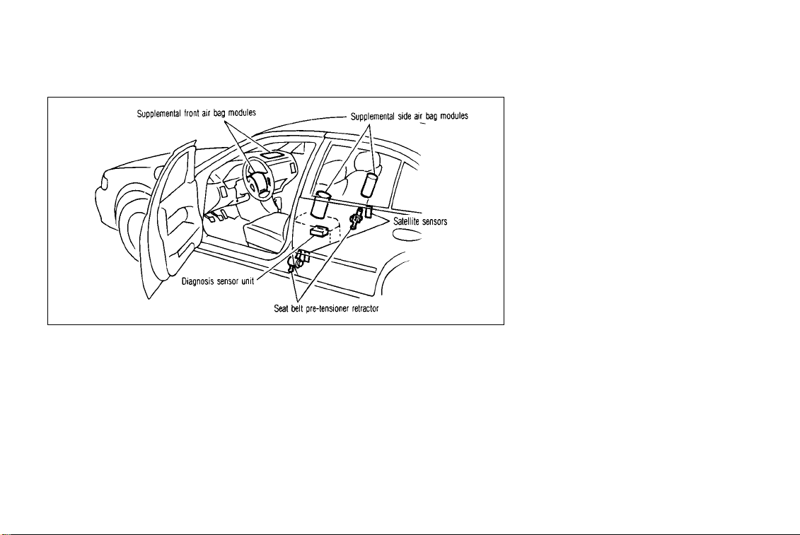
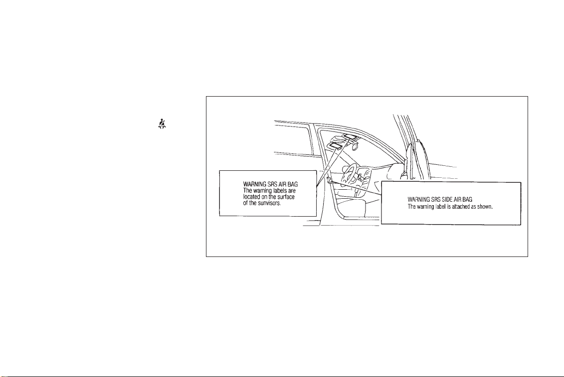
SIR0096D
Warning labels about the supplemental front
air bag system and supplemental side air bag
system are placed in the vehicle as shown in
the illustration.
1-19
Page 26

SEATS, RESTRAINTS AND SUPPLEMENTAL AIR BAG SYSTEMS
SUPPLEMENTAL AIR BAG
WARNING LIGHT
SIP0108
The supplemental air bag warning light, displaying AIR BAG in the instrument panel,
monitors the circuits of the supplemental front
air bag and supplemental side air bag systems. The circuits monitored by the air bag
warning light are the diagnosis sensor unit,
satellite sensors, front air bag modules, side
air bag modules and all related wiring.
After turning the ignition key to the ON
position, the supplemental air bag warning
1-20
light illuminates. The supplemental air bag
warning light will turn off after about 7
seconds if the system is operational.
If any of the following conditions occur, the
supplemental front air bag and supplemental
side air bag systems need servicing:
O The supplemental air bag warning light
remains on after approximately 7 seconds.
O The supplemental air bag warning light
flashes intermittently.
O The supplemental air bag warning light
does not come on at all.
Under these conditions, the supplemental
front air bags or supplemental side air bags
may not operate properly. They must be
checked and repaired. Take your vehicle to the
nearest authorized INFINITI dealer.
WARNING
If the supplemental air bag warning
light is on, it could mean that the
supplemental front air bag or supplemental side air bag system will not
operate in an accident.
Repair and replacement procedure
The supplemental front air bags or supplemental side air bags are designed to inflate on
a one-time-only basis. As a reminder, unless
it is damaged, the supplemental air bag
warning light will remain illuminated after
inflation has occurred. Repair and replacement
of these systems should be done only by
authorized INFINITI dealers.
To ensure long-term functioning, these
systems must be inspected 10 years after the date of manufacture noted on the
Page 27

SEATS, RESTRAINTS AND SUPPLEMENTAL AIR BAG SYSTEMS
certification label located on the driver
side center pillar.
When maintenance work is required on the
vehicle, the supplemental front air bags, side
air bags and related parts should be pointed
out to the person conducting the maintenance.
The ignition key should always be in the
LOCK position when working under the hood
or inside the vehicle.
WARNING
O
Once the supplemental front air
bag or side air bag has inflated,
the air bag module will not function again and must be replaced.
The air bag module should be replaced by an authorized INFINITI
dealer. The air bag modules cannot be repaired.
O
The supplemental front air bag
and side air bag systems should
be inspected by an authorized
INFINITI dealer if there is any
damage to the front end or side
portion of the vehicle.
O
If you need to dispose of these
supplemental systems or scrap
the vehicle, contact an authorized
INFINITI dealer.
Correct disposal procedures are
set forth in the appropriate
INFINITI Service Manual. Incorrect disposal procedures could
cause personal injury.
SEAT BEL TS
PRECAUTIONS ON SEAT BELT
USAGE
Your chances of being injured in an accident
and/or the severity of injury or killed may be
greatly reduced if you are wearing your seat
belt and it is properly adjusted. INFINITI
strongly encourages you and all of your
passengers to buckle up every time you drive,
even if your seating position includes a
supplemental air bag.
Most states, all provinces and territories requirethat seat beltsbe worn atall
times when a vehicle is being driven.
1-21
Page 28
SEATS, RESTRAINTS AND SUPPLEMENTAL AIR BAG SYSTEMS
ness of the entire restraint system
and increase the chance or severity of injuryinanaccident. Serious
injury or death can occur if the
seat belt is not worn properly.
O
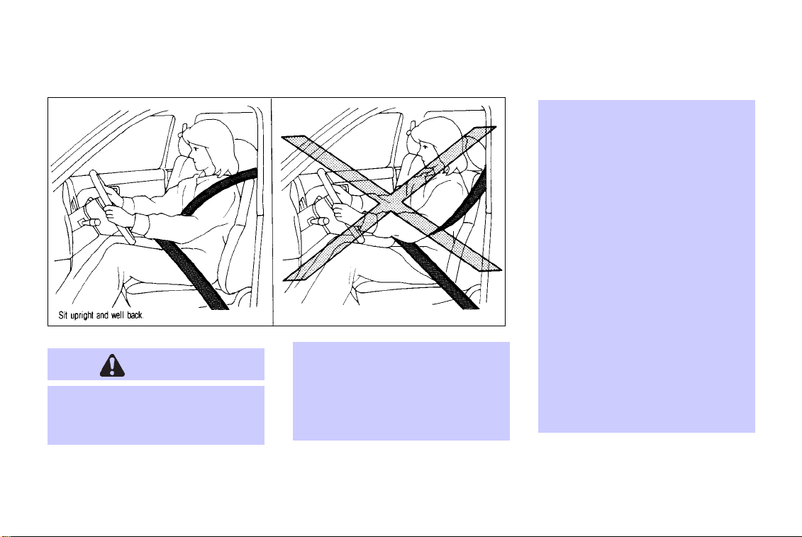
Always route the shoulder belt
over your shoulder and across
your chest. Never run the belt
behind your back, under your arm
or across your neck. The belt
should be away from your face
and neck, but not falling off your
shoulder.
O
Position the lap belt as low and
snug as possible AROUND THE
HIPS, NOT THE WAIST. A lap belt
worn too high could increase the
risk of internal injuries in an
accident.
WARNING
O
Every person who drives or rides
in this vehicle should use a seat
belt at all times. Children should
be properly restrained and, if appropriate, in a child restraint.
O
The belt should be properly adjusted to a snug fit. Failure to do
so may reduce the effective-
SIR0125
1-22
Page 29
SEATS, RESTRAINTS AND SUPPLEMENTAL AIR BAG SYSTEMS
SIR0102 SIR0016
O
Be sure the seat belt tongue is securely fastened to the proper
buckle.
O
Do not wear the belt inside out or
twisted. Doing so may reduce its
effectiveness.
O
Do not allow more than one per-
son to use the same belt.
O
Never carry more people in the
vehicle than there are seat belts.
O
If the seat belt warning light
glows continuously while the ignition is turned ON with all doors
closed and all seat belts fastened, it may indicate a malfunc-
1-23
Page 30

SEATS, RESTRAINTS AND SUPPLEMENTAL AIR BAG SYSTEMS
tion in the system. Have the system checked by your INFINITI
dealer.
O
Once the pre-tensioner has acti-
vated, it cannot be reused
1-24
SIR0014
and must be replaced together
with the retractor. See your
INFINITI dealer.
O
Removal and installation of the
pre-tensioner seat belt system
components should be done by an
authorized INFINITI dealer.
O
All seat belt assemblies including
retractors and attaching hardware
should be inspected after any collision by your INFINITI dealer.
INFINITI recommends that all
seat belt assemblies in use during a collision be replaced unless
the collision was minor and the
belts show no damage and continue to operate properly. Seat
belt assemblies not in use during
a collision should also be in-
spected and replaced if either
damage or improper operation is
noted.
CHILD SAFETY
Children need adults to help protect
them. They need to be properly restrained.
The proper restraint depends on the child’s
size. Generally, infants (up to about 1 year and
less than 20 lb (9 kg)) should be placed in
rear facing child restraints. Front facing child
restraints are available for children who outgrow rear facing child restraints.
WARNING
Infants and children need special
Page 31

SEATS, RESTRAINTS AND SUPPLEMENTAL AIR BAG SYSTEMS
protection. The vehicle’s seat belts
may not fit them properly. The
shoulder belt may come too close to
the face or neck. The lap belt may
not fit over their small hip bones. In
an accident, an improperly fitting
seat belt could cause serious or fatal
injury. Always use appropriate child
restraints.
All US states and provinces of Canada require
the use of approved child restraints for infants
and small children. (See “Child restraints”
later in this section.)
In addition, there are many types of child
restraints available for larger children which
should be used for maximum protection.
INFINITI recommends that all preteens
and children be restrained in the rear
seat if possible. According to accident
statistics, children are safer when prop-
erly restrained in the rear seat than in
the front seat.
This is especially important because
your vehicle has a supplemental restraint system (air bag system) for the
front passenger. See“Supplemental restraint system”earlier in this section for
precautions.
Infants and small children
INFINITI recommends that infants and small
children be placed in child restraints that
comply with Federal Motor Vehicle Safety
Standards or Canadian Motor Vehicle Safety
Standards. You should choose a child restraint which fits your vehicle and always
follow the manufacturer’s instructions for installation and use.
Larger children
Children who are too large for child restraints
should be seated and restrained by the seat
belts which are provided.
If the child’s seating position has a shoulder
belt that fits close to the face or neck, the use
of a booster seat (commercially available) may
help overcome this. The booster seat should
raise the child so that the shoulder belt is
properly positioned across the top, middle
portion of the shoulder and the lap belt is low
on the hips. The booster seat should fit the
vehicle seat and have a label certifying that it
complies with Federal Motor Vehicle Safety
Standards or Canadian Motor Vehicle Safety
Standards. Once the child has grown so the
shoulder belt is no longer on or near the face
and neck, use the shoulder belt without the
booster seat.
WARNING
Never let a child stand or kneel on
any seat and do not allow a child in
1-25
Page 32

SEATS, RESTRAINTS AND SUPPLEMENTAL AIR BAG SYSTEMS
the cargo areas while the vehicle is
moving. The child could be seriously
injured or killed in an accident or
sudden stop.
PREGNANT WOMEN
INFINITI recommends that pregnant women
use seat belts. The seat belt should be worn
snug, and always position the lap belt as low
as possible around the hips, not the waist, and
place the shoulder belt over your shoulder and
across your chest. Never run the lap/shoulder
belt over your abdominal area. Contact your
doctor for specific recommendations.
INJURED PERSONS
INFINITI recommends that injured persons
use seat belts, depending on the injury. Check
with your doctor for specific recommendations.
1-26
THREE-POINT TYPE SEAT BELT
WITH RETRACTOR
WARNING
O
Every person who drives or rides
in this vehicle should use a seat
belt at all times.
O
Do not ride in a moving vehicle
when the seatback is reclined.
This can be dangerous. The
shoulder belt will not be against
your body. In an accident you
could be thrown into it and receive neck or other serious injuries. You could also slide under
the lap belt and receive serious
internal injuries.
O
For most effective protection
when the vehicle is in motion, the
seat should be upright. Always sit
well back in the seat and adjust
the seat belt properly.
Fastening the seat belts
1. Adjust the seat.
SIR0126
Page 33

SEATS, RESTRAINTS AND SUPPLEMENTAL AIR BAG SYSTEMS
and allow you some freedom of movement in the seat.
SIR0127
SIR0019
2. Slowly pull the seat belt out of the retractor
and insert the tongue into the buckle until
it snaps.
The retractor is designed to lock during
a sudden stop or on impact. A slow pulling motion will permit the belt to move,
SIR0061
3. Position the lap belt portion low and
snug on the hips as shown.
4. Pull the shoulder belt portion toward the
retractor to take up extra slack.
The front passenger and rear seat belts have a
cinching mechanism for child restraint installation. It is referred to as the automatic locking
1-27
Page 34

SEATS, RESTRAINTS AND SUPPLEMENTAL AIR BAG SYSTEMS
mode. When the cinching mechanism is
activated the seat belt cannot be withdrawn
again until the seat belt tongue is detached
from the buckle and fully retracted. For additional information, see “Child restraints” later
in this section.
The automatic locking mode should be
used onlyfor child restraint installation.
During normal seat belt use by an occupant, thelocking modeshould not be activated. Ifit is activated it maycause uncomfortable seat belt tension.
1-28
Unfastening the seat belts
SIR0021
To unfasten the belt, press the button on the
buckle. The seat belt will automatically retract.
Checking seat belt operation
Your seat belt retractors are designed to lock
belt movement by two separate methods:
O when the belt is pulled quickly from the
retractor.
O when the vehicle slows down rapidly.
To increase your confidence in the belts,
check their operation as follows:
O grasp the shoulder belt and pull quickly
forward. The retractor should lock and
restrict further belt movement.
If the retractor does not lock during this check
or if you have any question about belt
operation, see your INFINITI dealer.
Page 35

SEATS, RESTRAINTS AND SUPPLEMENTAL AIR BAG SYSTEMS
Center of rear seat
Selecting correct set of seat belts:
SIR0097
The center seat belt buckle is identified by the
CENTER mark. The center seat belt tongue can
be fastened only into the center seat belt
buckle.
Shoulder belt height adjustment
(For front seats)
The shoulder belt anchor height should be
adjusted to the position best for you. See
earlier in “Seat belts” for precautions on seat
belt usage.
WARNING
O
After adjustment, release the adjustment button and try to move
the shoulder belt anchor up and
down to make sure it is securely
fixed in position.
O
The shoulder belt anchor height
should be adjusted to the position
best for you. Failure to do so may
reduce the effectiveness of the
entire restraint system and increase the chance or severity of
injury in an accident.
SIR0075
To adjust, pull the release knob, and then
move the shoulder belt anchor to the desired
position, so that the belt passes over the
center of the shoulder. The belt should be
away from your face and neck, but not falling
off of your shoulder. Release the adjustment
knob to lock the shoulder belt anchor into
position.
1-29
Page 36

SEATS, RESTRAINTS AND SUPPLEMENTAL AIR BAG SYSTEMS
SEAT BELT EXTENDERS
If, because of body size or driving position, it
is not possible to properly fit the lap-shoulder
belt and fasten it, an extender is available
which is compatible with the installed seat
belts. The extender adds approximately 8 in
(200 mm) of length and may be used for either
the driver or front passenger seating position.
See your INFINITI dealer for assistance if the
extender is required.
WARNING
O
Only INFINITI belt extenders,
made by the samecompany which
made the original equipment
belts, should be used with the
INFINITI belts.
O
Persons who can use the standard
seat belt should not use an ex-
1-30
tender. Such unnecessary use
could result in serious personal
injury in the event of an accident.
SEAT BELT MAINTENANCE
O To clean the seat belt webbings,
apply a mild soap solution or any noncaustic solution recommended for gently
cleaning cloth upholstery or carpets. Then
brush it, wipe with a cloth and allow it to
dry in the shade. Do not allow the seat
belts to retract until they are completely
dry.
O If dirt builds up in the shoulder belt guide
of the seat belt anchors, the seat belts may
retract slowly. Wipe the shoulder belt
guide with a clean, dry cloth.
O Periodically check to see that the
seat belt and the metal components
such as buckles, tongues, retractors, flex-
ible wires and anchors work properly. If
loose parts, deterioration, cuts or other
damage on the webbing are found, the
entire belt assembly should be replaced.
CHILD RESTRAINTS
PRECAUTIONS ON CHILD RESTRAINTS
WARNING
O
Infants and small children should
always be placed in an appropriate child restraint while riding in
the vehicle. Failure to use a child
restraint can result in serious injury or death.
O
Infants and small children should
never be carried on your lap. It is
not possible for even the strongest adult to resist the forces of a
Page 37

SEATS, RESTRAINTS AND SUPPLEMENTAL AIR BAG SYSTEMS
severe accident. The child could
be crushed between the adult and
parts of the vehicle. Also, do not
put the same seat belt around
both your child and yourself.
O
Never install a rear facing child
restraint in the front seat. An
inflating supplemental front air
bag could seriously injure or kill
your child. A rear facing child
restraint must only be used in the
rear seat.
O
INFINITI recommends that the
child restraint be installed in the
rear seat. According to accident
statistics, children are safer when
properly restrained in the rear
seat than in the front seat.
O
An improperly installed child restraint could lead to serious in
jury or death in an accident.
In general, child restraints are designed to be
installed with the lap portion of a three-point
type seat belt.
Child restraints for infants and children of various sizes are offered by several manufacturers.
When selecting any child restraint system,
keep the following points in mind:
O choose only a restraint with a label certi-
fying that it complies with Federal Motor
Vehicle Safety Standard 213 or Canadian
Motor Vehicle Safety Standard 213.
O check the child restraint in your vehicle to
be sure it is compatible with the vehicle’s
seat and seat belt system. Choose a child
restraint that meets the guidelines of the
Society of Automotive Engineers recommended practice J1819 for child restraint
installation.
O if the child restraint is compatible with
your vehicle, place your child in the child
restraint and check the various adjustments to be sure the child restraint is
compatible with your child. Always follow
all recommended procedures.
All US states and provinces of Canada
require that infants and small children
be restrained in approved child restraints at all times while the vehicle is
being operated.
WARNING
O
Improper use of a child restraint
can increase the riskor severity of
injury for both the infant or child
and other occupants in the vehicle.
O
Follow all of the child restraint
1-31
Page 38

SEATS, RESTRAINTS AND SUPPLEMENTAL AIR BAG SYSTEMS
manufacturer’s instructions for
installation and use. When purchasing a child restraint, be sure
to select one which will fit your
child and vehicle. It may not be
possible to properly install some
types of child restraints in your
vehicle.
O
If the child restraint is not anchored properly, the risk of a
child being injured in a collision
or a sudden stop greatly increases.
O
Adjustable seatbacks should be
positioned to fit the child restraint, but as upright as possible.
O
After attaching the child restraint,
test it before you place the child
in it. Tilt it from side to side. Try
1-32
to tug it forward and check to see
if the belt holds the restraint in
place. If the restraint is not secure, tighten the belt as necessary, or put the restraint in another seat and test it again.
O
For a front facing child restraint,
check to make sure the shoulder
belt does not go in front of the
child’s face or neck. If it does, put
the shoulder belt behind the child
restraint. If you must install a
front facing child restraint in the
front seat. See “Installation on
front passenger seat” later in this
section for details.
O
When your child restraint is not in
use, store it in the trunk or keep it
secured with a seat belt to prevent it from being thrown around
in case of a sudden stop or accident.
CAUTION
Remember that a child restraint left
in a closed vehicle can become very
hot. Check the seating surface and
buckles before placing your child in
the child restraint.
Page 39

SEATS, RESTRAINTS AND SUPPLEMENTAL AIR BAG SYSTEMS
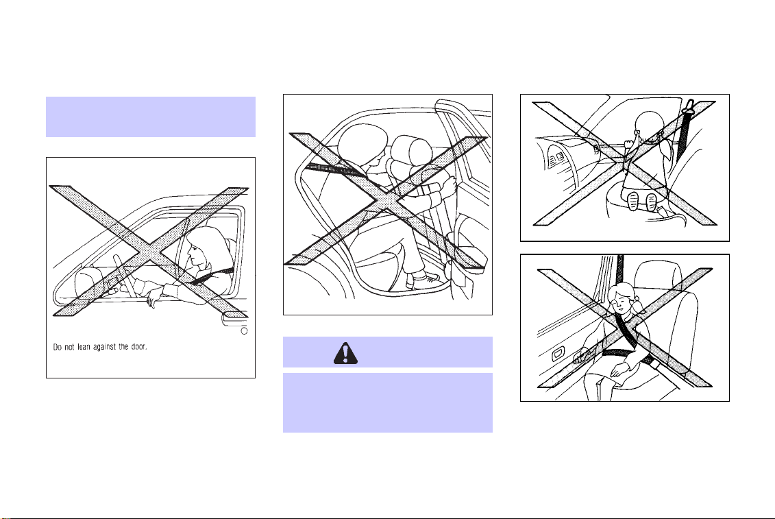
INSTALLATION ON REAR SEAT
CENTER OR OUTBOARD POSITIONS
Front facing
WARNING
O
The three-point belt on your vehicle is equipped with a locking
mode retractor which must be
used when installing a child restraint.
O
Failure to do so will result in the
child restraint not being properly
secured. It could tip over or otherwise be unsecured and cause
injury to the child in a sudden
stop or collision.
When you install a child restraint in a rear
outboard or center seat, follow these steps:
SIR0041A SIR0078
1. Position the child restraint on the seat. The
direction of the child restraint depends on
the type of the child restraint and the size
of the child. Always follow the restraint
manufacturer’s instructions.
1-33
Page 40

SEATS, RESTRAINTS AND SUPPLEMENTAL AIR BAG SYSTEMS
SIR0043 SIR0039A SIR0062
2. Route the seat belt tongue through the
child restraint and insert it into the buckle
until you hear and feel the latch engage. Be
sure to follow the child restraint manufacturer’s instructions for belt routing.
1-34
3. Pull on the shoulder belt until all of the
belt is fully extended. At this time, the belt
retractor is in the automatic locking mode
(child restraint mode). It reverts back to
emergency locking mode when the belt is
fully retracted.
4. Allow the belt to retract. Pull up on the belt
to remove any slack in the belt.
Page 41

SEATS, RESTRAINTS AND SUPPLEMENTAL AIR BAG SYSTEMS
SIR0042
5. Before placing the child in the child
restraint, use force to tilt the child restraint
from side to side, and tug it forward to
make sure that it is securely held in place.
6. Check that the retractor is in the automatic
locking mode by trying to pull more belt
out of the retractor. If you cannot pull any
more belt webbing out of the retractor, the
belt is in the automatic locking mode.
7. Check to make sure that the child restraint
is properly secured prior to each use. If the
lap belt is not locked, repeat steps 3
through 6.
After the child restraint is removed and the
seat belt is allowed to wind back into the
retractor, the automatic locking mode (child
restraint mode) is canceled; the seat belt only
locks during a sudden stop or impact.
Rear facing
WARNING
O
The three-point belt on your vehicle is equipped with a locking
mode retractor which must be
used when installing a child
restraint.
O
Failure to do so will result in the
child restraint not being properly
secured. It could tip over or otherwise be unsecured and cause
injury to the child in a sudden
stop or collision.
When you install a child restraint in a rear
outboard or center seat, follow these steps:
1-35
Page 42

SEATS, RESTRAINTS AND SUPPLEMENTAL AIR BAG SYSTEMS
SIR0044A SIR0079 SIR0046
1. Position the child restraint on the seat. The
direction of the child restraint depends on
the type of the child restraint and the size
of the child. Always follow the restraint
manufacturer’s instructions.
1-36
2. Route the seat belt tongue through the
child restraint and insert it into the buckle
until you hear and feel the latch engage. Be
sure to follow the child restraint manufacturer’s instructions for belt routing.
Page 43

SEATS, RESTRAINTS AND SUPPLEMENTAL AIR BAG SYSTEMS
SIR0045A SIR0047 SIR0048
3. Pull on the shoulder belt until all of the
belt is fully extended. At this time, the belt
retractor is in the automatic locking mode
(child restraint mode). It reverts back to
emergency locking mode when the belt is
fully retracted.
4. Allow the belt to retract. Pull up on the belt
to remove any slack in the belt.
5. Before placing the child in the child
restraint, use force to tilt the child restraint
from side to side, and tug it forward to
make sure that it is securely held in place.
6. Check that the retractor is in the automatic
locking mode by trying to pull more belt
out of the retractor. If you cannot pull any
1-37
Page 44

SEATS, RESTRAINTS AND SUPPLEMENTAL AIR BAG SYSTEMS
more belt webbing out of the retractor, the
belt is in the automatic locking mode.
7. Check to make sure that the child restraint
is properly secured prior to each use. If the
lap belt is not locked, repeat steps 3
through 6.
After the child restraint is removed and the
seat belt is allowed to wind back into the
retractor, the automatic locking mode (child
restraint mode) is canceled; the seat belt only
locks during a sudden stop or impact.
1-38
TOP TETHER STRAP CHILD RESTRAINT
SIR0100
If your child restraint has a top tether
strap, itmust be secured to the provided
anchor point. First, secure the child restraint with the rear seat belt.
Remove the anchor cover to which the top
tether strap stretches straight to.
Secure the top tether strap to the anchor
bracket.
Keep the removed cover in a secured place to
prevent loss or damage.
When you install a child restraint with a top
tether strap in a rear outboard seating position, the rear sun shade must be lowered
completely. See “Rear sun shade” in the “2.
Instruments and controls” section for rear sun
shade lowering information.
WARNING
The child restraint anchor points are
designed to withstand only those
loads imposed by correctly fitted
child restraints. Under no circumstances are they to be used for adult
seat belts or harnesses.
Page 45

SEATS, RESTRAINTS AND SUPPLEMENTAL AIR BAG SYSTEMS
Anchor point locations
SIR0128
Anchor points are located under the rear
parcel shelf finisher.
When installing a top strap child restraint on the rear seat for the first time,
consult your INFINITI dealer for details.
INSTALLATION ON FRONT
PASSENGER SEAT
WARNING
O
Never install a rear facing child
SIR0101
restraint in the front passenger
seat. Supplemental front air bags
inflate withgreat force. A rear fac-
1-39
Page 46

SEATS, RESTRAINTS AND SUPPLEMENTAL AIR BAG SYSTEMS
ing child restraint could be struck
by the air bag in a crash and
could seriously injure or kill your
child.
O
INFINITI recommends that child
restraints be installed in the rear
seat. However, if you must install
a forward facing child restraint in
the front passenger seat, move
the passenger seat to the rear
most position.
O
A child restraint with a top tether
strap should not be used in the
front passenger seat.
O
The three-point belt in your vehicle is equipped with a locking
mode retractor which must be
used when installing a child
restraint.
1-40
O
Failure to use the retractor’s locking mode will result in the child
restraint not being properly secured. The child restraint could
tip over or otherwise be unsecured and cause injury to the
child in a sudden stop or collision.
If you must install a child restraint in the front
seat, follow these steps:
SIR0103
1. Position the child restraint on the front
passenger seat. It should be placed in
a front facing direction only. Move the
seat to the rear most position. Always
follow the child restraint manufacturer’s
instructions. Child restraints for in-
fants must be used in the rear facing
direction and therefore must not be
Page 47

SEATS, RESTRAINTS AND SUPPLEMENTAL AIR BAG SYSTEMS
used in the front seat.
SIR0055
2. Route the seat belt tongue through the
child restraint and insert it into the buckle
until you hear and feel the latch engage. Be
sure to follow the child restraint manufacturer’s instructions for belt routing.
SIR0053A SIR0056
3. Pull on the shoulder belt until all of the
belt is fully extended. At this time, the belt
retractor is in the automatic locking mode
(child restraint mode). It reverts back to
emergency locking mode when the belt is
fully retracted.
4. Allow the belt to retract. Pull up on the belt
to remove any slack in the belt.
1-41
Page 48

SEATS, RESTRAINTS AND SUPPLEMENTAL AIR BAG SYSTEMS
more belt webbing out of the retractor, the
belt is in the automatic locking mode.
7. Check to make sure that the child restraint
is properly secured prior to each use. If the
lap belt is not locked, repeat steps 3
through 6.
After the child restraint is removed and the
seat belt is allowed to wind back into the
retractor, the automatic locking mode (child
restraint mode) is canceled; the seat belt only
locks during a sudden stop or impact.
SIR0063
5. Before placing the child in the child
restraint, use force to tilt the child restraint
from side to side, and tug it forward to
make sure that it is securely held in place.
6. Check that the retractor is in the automatic
locking mode by trying to pull more belt
out of the retractor. If you cannot pull any
1-42
Page 49

Page 50

2 INSTRUMENTS AND CONTROLS
Instrument panel ......................................... 2-2
Instrument panel (if so equipped) ............. 2-3
Meters and gauges ...................................... 2-4
Speedometer and odometer................... 2-5
Tachometer............................................. 2-5
Engine coolant temperature gauge ........ 2-6
Fuel gauge .............................................. 2-6
Warning/indicator lights and chimes .......... 2-8
Checking bulbs....................................... 2-8
Warning lights ........................................ 2-9
Indicator lights ..................................... 2-11
Chimes.................................................. 2-14
Security systems ....................................... 2-15
Vehicle security .................................... 2-15
Infiniti Vehicle Immobilizer System ..... 2-16
Windshield wiper and washer switch........ 2-17
Switch operation .................................. 2-17
Stopping position adjustment
mechanism ........................................... 2-18
Rear window and outside mirror defogger
switch ........................................................ 2-19
Headlight and turn signal switch............... 2-20
Xenon headlights.................................. 2-20
Headlight switch................................... 2-21
Turn signal switch................................ 2-24
Front fog light switch ................................ 2-24
Hazard warning flasher switch .................. 2-24
Horn........................................................... 2-25
Heated sea ts (if so equipped)................... 2-26
Traction control system (TCS) cancel
switch ........................................................ 2-27
Active damper suspension mode select
switch (if so equipped).............................. 2-27
Auto mode............................................ 2-27
Sport mode .......................................... 2-27
Power outlet .............................................. 2-28
Cigarette lighters and ashtrays.................. 2-29
Storage ...................................................... 2-30
Cup holders .......................................... 2-30
Glove box ............................................. 2-31
Console box.......................................... 2-31
Windows.................................................... 2-32
Power windows .................................... 2-32
Sunroof...................................................... 2-34
Page 51

Automatic sunroof................................ 2-34
Rear sun shade ......................................... 2-36
Clock.......................................................... 2-37
Adjusting the time................................ 2-37
Interior lights............................................. 2-37
Personal lights........................................... 2-38
Front..................................................... 2-38
Rear...................................................... 2-39
Vanity mirror lights ................................... 2-39
Trunk light ................................................. 2-39
Integrated HomeLinkT Universal
Transceiver ................................................ 2-39
Programming HomeLinkT.................... 2-41
Programming HomeLinkT for Canadian
customers ............................................ 2-41
Operating the integrated HomeLinkT
Universal Transceiver........................... 2-42
Programming trouble diagnosis .......... 2-42
Clearing the programmed
information........................................... 2-42
Rolling code programming .................. 2-42
Programming a single HomeLinkT
button................................................... 2-43
If your vehicle is stolen ....................... 2-43
Infiniti communicator (if so equipped) .... 2-44
Infiniti communicator purpose............. 2-45
Infiniti communicator outline............... 2-45
Safe operating recommendations ........ 2-45
Quick summary .................................... 2-45
Functions.............................................. 2-46
Function and description...................... 2-48
Infiniti communicator indicator
description............................................ 2-52
Payment for Infiniti communicator
use........................................................ 2-53
System limitations................................ 2-53
False activations and password
selections ............................................. 2-55
Steering wheel switch for cellular phone (Mod-
els with Infiniti Communicator)................. 2-56
Switch operations ................................ 2-56
Page 52

INSTRUMENTS AND CONTROLS
INSTRUMENT PANEL
2-2
See the page indicated in parentheses for operating details.
SII0212
Page 53

INSTRUMENT PANEL (if so equipped)
INSTRUMENTS AND CONTROLS
See the page indicated in parentheses for operating details.
SII0285
2-3
Page 54

INSTRUMENTS AND CONTROLS
METERS AND GAUGES
2-4
80
120
km/h
MPH
160
100
120
160
P
R
200
140
240
2
N
D
1
2
1
60
80
40
E
40
20
0
0
4
3
x1000r/min
0
5
6
7
CF
H
8
SII0213
Page 55

INSTRUMENTS AND CONTROLS
SPEEDOMETER AND ODOMETER
SII0214
Speedometer
The speedometer indicates vehicle speed.
Odometer/twin trip odometer
The odometer/twin trip odometer are displayed when the ignition key is in the ON
position.
The odometer records the total distance the
vehicle has been driven.
The twin trip odometer records the distance of
individual trips.
SII0181
Changing the display:
Pushing the reset knob changes the display as
follows:
ODO → TRIP A → TRIP B → ODO
Resetting the trip odometer:
Pushing the reset knob for more than 1
second resets the trip odometer to zero.
TACHOMETER
SII0182
The tachometer indicates engine speed in
revolutions per minute (r/min).
CAUTION
When engine speed approaches the
red zone, shift to a higher gear. Operating the engine in the red zone
may cause serious engine damage.
2-5
Page 56

INSTRUMENTS AND CONTROLS
ENGINE COOLANT TEMPERATURE GAUGE
The gauge indicates the engine coolant temperature.
SII0075
The engine coolant temperature will vary with
the outside air temperature and driving conditions.
If the gauge indicates engine coolant
temperature over the normal range,
stop the vehicle as soon as safely
possible. Ifthe engine is overheated,
continued operation of the vehicle
may seriously damage the engine.
See the “In case of emergency” section for immediate action required.
FUEL GAUGE
The gauge indicates the approximate fuel level
in the tank.
CAUTION
SII0076
The gauge may move slightly during braking,
turning, acceleration, or going up or down
hill.
The gauge needle is designed to remain in
approximately the same position, even when
the ignition key is turned OFF.
Refill thefuel tank before thegauge registers Empty.
The indicator light comes on when the fuel
tank is getting low. Refuel as soon as it is
convenient, preferably before the gauge
2-6
Page 57

reaches “E”. There will be a small reserve of
fuel in the tank when the fuel gauge needle
reaches “E”.
CAUTION
O
If the vehicle runs out of fuel, the
malfunction indicator lamp
(MIL) may come on. Refuel as
soon as possible. After a few driving trips, the
turn off. If the lamp remains on after a few drivingtrips, havethe vehicle inspected by an authorized
INFINITI dealer.
O
For additional information, see
“Malfunction indicator lamp
(MIL)” later in this section.
lamp should
INSTRUMENTS AND CONTROLS
2-7
Page 58

INSTRUMENTS AND CONTROLS
WARNING/INDICATOR LIGHTS AND CHIMES
Engine oil pressure warning light Stop/tail warning light Slip indicator light
Charge warning light Overdrive off indicator light
Door open warning light Turn signal/hazard indicator lights
Seat belt warning light High beam indicator light (Blue)
Supplemental air bag warning light Cruise main switch indicator light
Low washer fluid warning light Cruise set indicator light
or Brake warning light Malfunction indicator light (MIL)
or
Anti-lock brake system
warning light
Traction control system indicator light
Sport mode indicator light (if so
equipped)
Infiniti Communicator redial indicator
light (if so equipped)
Infiniti Communicator no service indicator light (if so equipped)
Infiniti Communicator “Mayday” emergency button indicator light (if so
equipped)
Infiniti Communicator “Information” button indicator light (if so equipped)
CHECKING BULBS
Apply the parking brake and turn the ignition
key to ON without starting the engine. The
following lights will come on:
, or , , ,
2-8
or , ,
The following lights come on briefly and then
go off:
, , , , ,
If any light fails to come on, it may indicate a
burned-out bulb or an open circuit in the
electrical system. Have the system repaired
promptly.
Page 59

INSTRUMENTS AND CONTROLS
WARNING LIGHTS
Engine oil pressure warning light
This light warns of low engine oil pressure. If
the light flickers or comes on during normal
driving, pull off the road in a safe area, stop
the engine immediately and call an INFINITI
dealer or other authorized repair shop.
The oil pressure warning light is not designed to indicate a low oil level. Use
the dipstick to check the oil level. See
“Engine oil” in the “8. Do-it-yourself” section.
CAUTION
Running the engine with the oil pressure warning light on could cause serious damage to the engine almost
immediately. Turn off the engine as
soon as it is safe to do so.
Charge warning light
If the light comes on while the engine is
running, it may indicate the charging system
is not functioning properly. Turn the engine
off and check the alternator belt. If the belt is
loose, broken, missing or if the light remains
on, see your INFINITI dealer immediately.
CAUTION
Do not continue driving if the belt is
loose, broken or missing. See “If
your vehicle overheats” in the “6. In
case of emergency” section.
Door open warning light
This light comes on when any of the doors are
not closed securely while the ignition key is
ON.
Seat belt warning light
and chime
The light and chime remind you to fasten seat
belts. The light illuminates whenever the
ignition key is turned to ON, and will remain
illuminated until the driver’s seat belt is
fastened. (When the ignition key is turned to
ON with the driver’s seat belt fastened, the
light will illuminate for about 7 seconds and
then go off.) At the same time, the chime will
sound for about 6 seconds unless the driver’s
seat belt is securely fastened.
See “Seat belts” in the “1. Seats, restraints
and supplemental air bag systems” section for
precautions on seat belt usage.
If the seat belt warning light blinks, there may
be something wrong with the pre-tensioner
seat belt. In this case, the pre-tensioner will
not operate properly. Have it checked by your
INFINITI dealer.
For additional information, see “Supplemental
2-9
Page 60

INSTRUMENTS AND CONTROLS
restraint system” in the “1. Seats, restraints
and supplemental air bag systems” section.
Supplemental air bag
warning light
After turning the ignition key to the ON
position, the supplemental air bag warning
light illuminates. The supplemental air bag
warning light will turn off after about 7
seconds if the supplemental front air bag and
supplemental side air bag systems are operational.
If any of the following conditions occur, the
supplemental front air bag and supplemental
side air bag needs servicing and your INFINITI
must be taken to your nearest authorized
INFINITI dealer.
O The supplemental air bag warning light
remains on after approximately 7 seconds.
O The supplemental air bag warning light
flashes intermittently.
2-10
O The supplemental air bag warning light
does not come on at all.
Unless checked and repaired, the supplemental restraint system may not function properly.
For additional information, see “Supplemental
restraint system” in the “1. Seats, restraints
and supplemental air bag systems” section.
WARNING
If the supplemental air bag warning
light is on, it could mean that the
supplemental air bag or supplemental side air bag systems will not operate in an accident.
Low washer fluid warning
light
This light comes on when the washer tank
fluid is at a low level. Add washer fluid as
necessary. See “Window washer fluid” in the
“8. Do-it-yourself” section.
or Brake warning
light
This light functions for both the parking brake
and the foot brake systems.
Parking brake indicator:
When the ignition key is in the ON position,
the light comes on when the parking brake is
applied.
Low brake fluid warning light:
When the ignition key is in the ON position,
the light warns of a low brake fluid level. If the
light comes on while the engine is running
with the parking brake not applied, stop the
vehicle and perform the following:
1. Check the brake fluid level. Add brake fluid
as necessary. See “Brake fluid” in the “8.
Do-it-yourself” section.
2. If the brake fluid level is correct:
Page 61

INSTRUMENTS AND CONTROLS
Have the warning system checked by an
INFINITI dealer.
WARNING
O
Your brake system may not be
working properly if the warning
light is on. Driving could be dangerous. If you judge it to be safe,
drive carefully to the nearest service station for repairs. Otherwise, have your vehicle towed.
O
Pressing the brake pedal with the
engine stopped and/or low brake
fluid level may increase your
stopping distance and braking
will require greater pedal effort
as well as pedal travel.
O
If the brake fluid level is below
the MINIMUM or MIN mark on the
brake fluid reservoir, do not drive
until the brake system has been
checked at an INFINITI dealer.
or Anti-lock brake
warning light
If the light comes on while the engine is
running, it may indicate the anti-lock brake
system is not functioning properly. In either
case, have the system checked by your INFINITI dealer.
If an abnormality occurs in the system, the
anti-lock function will cease but the ordinary
brakes will continue to operate normally.
If the light comes on while you are driving, contact your INFINITI dealer for repair.
Stop/tail warning light
If the light comes on with the engine running
and with the light switch on, or when the brake
pedal is depressed, one or more stop/tail light
bulbs are burned out. Replace the stop/tail
light bulb.
INDICATOR LIGHTS
Overdrive off indicator
light
This light comes on during driving when the
overdrive switch is pressed to prevent overdrive operation.
The O/D OFF indicator light comes on for 2
seconds each time the ignition key is turned
ON. This shows the light is functioning
properly.
If the O/D OFF indicator light blinks for approximately 8 seconds after coming on for 2 seconds,
have your INFINITI dealer check the transmission
and repair it if necessary.
The automatic transmission is equipped with
an electronic fail-safe mode. This system
allows the vehicle to be driven even in the
2-11
Page 62

INSTRUMENTS AND CONTROLS
event of damage to the electrical circuits. If
this occurs, the gears automatically engage
and lock into third gear.
See the “Driving the vehicle” in the “5.
Starting and driving” section for fail-safe
before visiting your INFINITI dealer.
Turn signal/hazard indicator lights
The light flashes when the turn signal switch
lever or hazard switch is turned on.
High beam indicator light
(Blue)
This light comes on when the headlight high
beam is on and goes out when the low beam
is selected.
Cruise main switch indicator light
The light comes on when the cruise control
main switch is pushed. The light goes out
when the main switch is pushed again. While
2-12
the cruise main switch indicator light comes
on, the cruise control system is operational.
Cruise set indicator light
The light comes on while the vehicle speed is
controlled by the cruise control system. If the
light flickers while the engine is running, it
may indicate the cruise control system is not
functioning properly. Have the system
checked by your INFINITI dealer.
Malfunction indicator
lamp (MIL)
If the malfunction indicator lamp comes on
steady or blinks while the engine is running,
it may indicate a potential emission control
malfunction.
The malfunction indicator lamp may also
come on steady if the fuel filler cap is loose or
missing, or if the vehicle runs out of fuel.
Check to make sure the fuel filler cap is
installed and closed tightly, and that the
vehicle has at least 3 US gallons (14 liters) of
fuel in the fuel tank.
After a few driving trips, the
should turn off if no other potential emission
control system malfunction exists.
Operation
The malfunction indicator lamp will come on
in one of two ways:
O Malfunction indicator lamp on steady —
An emission control system malfunction
has been detected. Check the fuel filler
cap. If the fuel filler cap is loose or
missing, tighten or install the cap and
continue to drive the vehicle. The
lamp should turn off after a few
driving trips. If the
turn off after a few driving trips, have the
vehicle inspected by an authorized
INFINITI dealer. You do not need to have
your vehicle towed to the dealer.
O Malfunction indicator lamp blinking — An
lamp does not
lamp
Page 63

INSTRUMENTS AND CONTROLS
engine misfire has been detected which
may damage the emission control system.
To reduce or avoid emission control system damage:
a) Do not drive at speeds above 45 MPH
(72 km/h).
b) Avoid hard acceleration or deceleration.
c) Avoid steep uphill grades.
d) If possible, reduce the amount of cargo
being hauled or towed.
The malfunction indicator lamp may stop
blinking and come on steady.
Have the vehicle inspected by an autho-
rized INFINITI dealer. You do not need to
have your vehicle towed to the dealer.
CAUTION
Continued vehicle operation without
having the emission control system
checked and repaired as necessary
could lead to poor driveability, reduced fuel economy, and possible
damage to the emission control
system.
Traction control system
indicator light
When the traction control system switch is off,
this light comes on. When the traction control
system indicator light and slip indicator light
come on with the traction control system
switch turned on, this light alerts the driver to
the fact that the traction control system’s
fail-safe mode is operating i.e. that the traction
control system is temporarily out of order.
Have the system checked by your INFINITI
dealer. If an abnormality occurs in the system,
the traction control function will be canceled
but the vehicle can still be driven. For
additional information, see “Traction control
system” in the “5. Starting and driving”
section.
Slip indicator light
This indicator will blink when the traction
control system is operating, thus alerting the
driver to the fact that the road surface is
slippery and the vehicle is nearing its traction
limits.
Sport mode indicator light
(if so equipped)
This light comes on when the active damper
suspension mode select switch is set to the
SPORT position.
Infiniti Communicator redial indicator light (if so
equipped)
After turning the ignition key to the ON
position, the redial indicator light will illuminate for up to 30 seconds and then turn off.
This indicator light comes on when the initial
2-13
Page 64

INSTRUMENTS AND CONTROLS
connection is not successful. The Infiniti
Communicator is attempting to redial to contact the Infiniti Response Center. The redial
indicator may blink before the button indicator
blinks. See “Infiniti Communicator” later in
this section.
Infiniti Communicator no
service indicator light (if
so equipped)
After turning the ignition key to the ON
position, the no service indicator light will
illuminate for up to 30 seconds and then turn
off.
This indicator light comes on when the
cellular phone is outside of cellular phone
transmission range. The Infiniti Communicator will not be able to contact the Infiniti
Response Center. See “Infiniti Communicator” later in this section.
2-14
Infiniti Communicator
“Mayday” emergency button indicator light (if so
equipped)
After turning the ignition key to the ON
position, the “Mayday” emergency button
indicator light will illuminate for up to 30
seconds and then turn off if the system is
operational.
This button indicator light comes on when the
“Mayday” emergency button is pressed. When
the light is blinking, Infiniti Communicator is
trying to acquire an available cellular channel.
When the light is ON, the system is connected
to a cell and is communicating information to
the Infiniti Response Center. See “Infiniti
Communicator” later in this section.
Infiniti Communicator “Information” button indicator light (if so equipped)
After turning the ignition key to the ON
position, the “Information” button indicator
light will illuminate for up to 30 seconds and
then turn off if the system is operational.
This button indicator light comes on when the
“Information” button is pressed. When the
light is blinking, Infiniti Communicator is
trying to acquire an available cellular channel.
When the light is ON, the system is connected
to a cell and is communicating information to
the Infiniti Response Center. See “Infiniti
Communicator” later in this section.
CHIMES
Key reminder chime
The chime will sound if the driver side door is
opened while the key is left in the ignition
switch (ignition switch is turned off). Remove
the key and take it with you when leaving the
vehicle.
Light reminder chime
A chime will sound when the driver side door
Page 65

INSTRUMENTS AND CONTROLS
is opened if the light switch is in the or
position (ignition switch is turned off).
Turn the light switch off when you leave the
vehicle.
Brake pad wear warning
The disc brake pads have audible wear warnings. When a brake pad requires replacement,
it will make a high pitched scraping sound
when the vehicle is in motion whether or not
the brake pedal is depressed. Have the brakes
checked as soon as possible if the warning
sound is heard.
SECURITY SYSTEMS
Your vehicle has two types of security systems, as follows:
O Vehicle security
O Infiniti Vehicle Immobilizer System
The security condition will be shown by the
security indicator light.
VEHICLE SECURITY
The vehicle security system provides visual
and audio alarm signals to deter theft of the
vehicle.
Security indicator light
SII0215
How to activate the vehicle security system
1. Close all windows.
The system can be activated even if the
windows are open.
2. Remove the key from the ignition switch.
3. Close and lock all doors, hood and trunk
lid. The doors can be locked either with a
key, multi-remote controller or door lock
knob.
4. Confirm that the security indicator light
comes on. The security light glows for
about 30 seconds and then blink. The
system is now activated. If, during this 30
second time period, the door or trunk lid is
unlocked by the key or the multi-remote
controller, or the ignition key is turned to
ACC or ON, the system will not activate.
However, when the trunk lid is closed after
being unlocked with a key or multi-remote
controller, the system returns to the armed
phase.
O If the key is turned slowly toward the
front of the vehicle when locking the
door, the system may not activate. If
the key is returned beyond the vertical position toward the rear of the ve-
2-15
Page 66

INSTRUMENTS AND CONTROLS
hicle to remove the key, the system
may be deactivated. When the indicator light fails to glow for 30 seconds, unlock the door once and lock
it again.
O Even when the driver and/or passen-
gers are in the vehicle, the system
will activate with alldoors,hood, and
trunk lid locked and ignition key off.
When turning the ignition toACC, the
system will be released.
Vehicle security system operation
The warning system will give the following
alarm:
O the headlights blink and the horn sounds
intermittently.
O the alarm automatically turns off after 2 to
3 minutes; however, the alarm will reactivate if the vehicle is tampered with again.
The alarm is activated by:
2-16
O Unlocking the door or opening the trunk
lid without using the key or multi-remote
controller. (Even if the door is opened by
releasing the door inside lock knob or the
trunk lid is opened by operating the trunk
lid release switch, the alarm is activated.)
O Opening the hood.
How to stop alarm
The alarm will stop by unlocking a door or
trunk lid with the key or by pushing either the
unlock or trunk lid release button on the multiremote controller. The alarm will not stopif the
ignition switch is turned to ACC or ON.
If the system does not operate as described above, have it checked by your
INFINITI dealer.
INFINITI VEHICLE IMMOBILIZER SYSTEM
The Infiniti Vehicle Immobilizer System will
not allow the engine to start without the use of
the registered Infiniti Vehicle Immobilizer System key.
If the engine fails to start using the registered
Infiniti Vehicle Immobilizer System key (for
example, when interference is caused by
another Infiniti Vehicle Immobilizer System
key, an automated toll road device or automated payment device on the key ring), restart
the engine using the following procedures:
1. Leave the ignition switch in the ON position for approximately 5 seconds.
2. Turn the ignition switch to the OFF or
LOCK position, and wait approximately 5
seconds.
3. Repeat step 1 and 2.
4. Restart the engine while holding the device
(which may have caused the interference)
separate from the registered Infiniti Vehicle
Immobilizer System key.
If the no start condition re-occurs, INFINITI
Page 67

INSTRUMENTS AND CONTROLS
recommends placing the registered Infiniti
Vehicle Immobilizer System key on a separate
key ring to avoid interference from other
devices.
Statement related to section 15 of FCC
rules for Infiniti Vehicle Immobilizer
System
(CONT ASSY - IMMOBILIZER, ANT ASSY
- IMMOBILIZER)
This device complies with part 15 of the
FCC Rules and RSS-210 of Industry
Canada. Operation is subject to the following two conditions;
(1) This device may not cause harmful
interference, and (2) this device must
accept any interference received, including interference that may cause undesired operation of the device.
CHANGES OR MODIFICATIONS NOT EXPRESSLY BY THE MANUFACTURE FOR
COMPLIANCE COULD VOID THE USER’S
AUTHORITY TO OPERATE THE EQUIPMENT.
Security indicator light
SII0215
This light blinks whenever the ignition switch
is in the LOCK, OFF or ACC position. This
function indicates the security systems
equipped on the vehicle are operational.
If the Infiniti Vehicle Immobiliser System is
malfunctioning, this light will remain on while
the ignition key is in the ON position.
If the light still remains on and/ortheen-
gine will not start, see your INFINITI
dealer for Infiniti Vehicle Immobiliser
System service as soon as possible.
Please bring all Infiniti Vehicle Immobiliser System keys that you have
when visiting your INFINITI dealer for
service.
WINDSHIELD WIPER AND
WASHER SWITCH
IIC041-A
SWITCH OPERATION
The windshield wiper and washer operates
2-17
Page 68

INSTRUMENTS AND CONTROLS
when the ignition key is in the ACC or ON
position.
Push the lever down to operate the wiper. Pull
the lever toward you to operate the washer.
The intermittent operation time can be adjusted by turning the knob as follows:
O While driving: from 0.4 to 12 seconds
O While stopped: from 4 to 20 seconds
WARNING
In freezing temperatures the washer
solution may freeze on the windshield and obscure your vision which
may leadto an accident.Warm windshield with the defroster before you
wash the windshield.
2-18
CAUTION
The following could damage the
washer system:
O
Do not operate the washer continuously for more than 30 seconds.
O
Do not operate the washer if the
reservoir tank is empty.
STOPPING POSITION ADJUSTMENT MECHANISM
SII0231
The stopping position of the windshield wiper
can be set manually, if necessary.
1. With the wiper stopped at the pre-set
position, hold part (A) that connects the
arm and the blade on each wiper set.
Page 69

INSTRUMENTS AND CONTROLS
2. Apply force to the moving direction of the
wiper, to the next locking position.
When the windshield wiper is used in
snow, the stopping position of the
blades may automatically be adjusted to
compensate for the snow accumulation
on the windshield. This should not be regarded as abnormal. In case the wiper
stops operating, turn the wiper switch
off, remove the accumulated snow, and
turn thewiper switch back on. The wiper
should function normally.
REAR WINDOW AND OUT SIDE MIRROR DEFOGGER
SWITCH
SII0216A
SII0286
To defog/defrost the rear window glass and
the outside mirrors, start the engine and push
the switch on. (The indicator light will come
on.) Push the switch again to turn the defogger off.
It will automatically turn off in approximately
15 minutes.
CAUTION
When cleaning the inner side of the
2-19
Page 70

INSTRUMENTS AND CONTROLS
rear window, be careful not to
scratch or damage the rear window
defogger.
HEADLIGHT AND TURN
SIGNAL SWITCH
XENON HEADLIGHTS
WARNING
HIGH VOLTAGE
O
When xenon headlights are on,
they produce a high voltage. To
prevent an electric shock, never
attempt to modify or disassemble. Always have your xenon
headlights replaced at an authorized INFINITI dealer.
2-20
O
Xenon headlights provide considerably more light than conventional headlights. If they are not
correctly aimed, they might temporarily blind an oncoming driver
or the driver ahead of you and
cause a serious accident. If headlights are not aimed correctly,
immediately take your vehicle to
an authorized INFINITI dealer and
have the headlights adjusted correctly.
When the xenon headlight is initially turned
on, its brightness or color varies slightly.
However, the color and brightness will soon
stabilize.
O The life of xenon headlights will be
shortened by frequent on-off operation. It is generally desirable not to
turn off the headlights for short inter-
vals, (for example, when the vehicle
stops at a traffic signal). Even when
the daytime running lights are active
(Canada only), the xenon headlights
do notturn on. Thisway the lifeof the
xenon headlights is not reduced.
O If the xenon headlightbulb is close to
burning out, the brightness will drastically decrease, the light will start
blinking, or the color of the light will
become reddish.If one or more ofthe
above signs appear, contact an
INFINITI dealer.
Page 71

INSTRUMENTS AND CONTROLS
HEADLIGHT SWITCH
Lighting
SII0079
Turn the switch to the AUTO position:
When the ignition key is in the ON position,
the parking light, headlight, instrument lights
and other lights turn on automatically, depending on the brightness of the surroundings. When the ignition key is turned to the
ACC, OFF or LOCK position with the autolamp
switch in the maximum short position, the
light will turn off automatically. See later in
this section for autolamp shut-off delay.
When the light switch is turned to the
position, the headlight low or high
beam will turn off.
Turn the switch to the
The parking, side marker, tail, license plate
and instrument lights will come on.
Turn the switch to the
Headlights will come on and all the other
lights remain on.
position:
position:
Headlight aiming control
SII0224
Depending on the number of occupants in the
vehicle and the load it is carrying, the headlight axis may be higher than desired. If the
vehicle is traveling on a hilly road, the
headlights may directly hit the rearview mirror
of the vehicle ahead or the windshield of the
oncoming vehicle. The light axis can be
lowered with the operation of the switch.
The larger the number designated on the
switch, the lower the axis.
2-21
Page 72

INSTRUMENTS AND CONTROLS
When traveling with no heavy load or on a flat
road, select position 0.
Xenon headlights are extremely bright
compared to conventional headlights. If
the xenon headlights hit the rearview
mirror of the vehicle ahead or the windshield of the oncoming vehicle, the
driver of these vehicles may have difficulty driving because of the brightness.
Use the headlight aiming control switch
to lower thelight axis.Seeearlier in this
section for information on xenon headlights.
2-22
Instrument brightness control
SII0085
The instrument brightness control operates
when the light switch is in the AUTO (ignition
key is in the ON),
Turn the control to adjust the brightness of
instrument panel lights and power window
switch lights.
When the control is turned in the upper
direction until a click sound is heard, the light
intensity will be at maximum. When the
control is turned in the lower direction until a
or position.
click sound is heard, the light will be turned
off.
Headlight beam select
SII0080
To select the high beam, push the lever
forward. Pull it back to select the low beam.
Passing signal
Pulling the lever toward you will flash the
headlight high beam.
Page 73

INSTRUMENTS AND CONTROLS
Daytime running light system
(Canada only)
The headlights automatically illuminate at a
reduced intensity when the engine is started
with the parking brake released. The daytime
running lights operate with the headlight
switch in the OFF position or in the
sition. Turn the headlight switch to the
position for full illumination when driv-
ing at night.
If the parking brake is applied before the
engine is started, the daytime running lights
do not illuminate. The daytime running lights
illuminate once the parking brake is released.
The daytime running lights will remain on
until the ignition switch is turned off.
po-
WARNING
When the daytime running light sys-
tem is active, tail lights on your
vehicle are not on. It is necessary at
dusk to turn on your headlights.
Failure to do so could cause an
accident injuring yourself and others.
Autolamp shut-off delay
SII0217
The length of time the autolamps stay on after
the ignition key is turned to OFF while
headlight switch is in the AUTO position
depends on how far the autolamp switch is
turned. If the switch is turned fully in the
above direction, the headlights will stay on for
a longer time (a few minutes).
SII0082
Be sure not to put anything on top of the
photo sensor located on the top lefthand side of the instrument panel. The
photo sensor controls the autolamp; if it
is covered, the photo sensor reacts as if
it is dark and the headlights will illuminate.
2-23
Page 74

INSTRUMENTS AND CONTROLS
TURN SIGNAL SWITCH
Turn signal
SII0083
Move the lever up or down to signal the
turning direction. When the turn is completed,
the turn signals cancel automatically.
Lane change signal
To indicate a lane change, move the lever up
or down to the point where lights begin
flashing.
2-24
FRONT FOG LIGHT SWITCH
SII0084
Turn the knob to activate the fog lights. The
fog lights can only be activated when the
headlight is turned on.
HAZARD WARNING
FLASHER SWITCH
SII0086A
Page 75

INSTRUMENTS AND CONTROLS
SII0261A
Push the switch on to warn other drivers when
you must stop or park under emergency conditions. All turn signal lights will flash.
WARNING
O
If stopping for an emergency, be
sure to move the vehicle well off
the road.
O
Do not use the hazard warning
flashers while moving on the
highway unless unusual circumstances force you to drive so
slowly that your vehicle might
become a hazard to other traffic.
O
Turn signals do not work when
the hazard warning flasher lights
are on.
The flasher can be actuated with the ignition
switch either off or on.
Some state laws may prohibit the use of
the hazard warning flasher switch while
driving.
HORN
SII0175
To sound the horn, push the center pad area
of the steering wheel.
2-25
Page 76

INSTRUMENTS AND CONTROLS
HEATED SEATS (if so
equipped)
SII0087
The front seats are warmed by built-in heaters.
The switches located on the center console
can be operated independently of each other.
1. Start the engine.
2-26
2. Push the low or high position of the
switch, as desired, depending on the temperature. The indicator light in the switch
will illuminate.
The heater is controlled by a thermostat,
automatically turning the heater on and off.
The indicator light will remain on as long
as the switch is on.
3. When the seat is warmed or before you
leave the vehicle, be sure to turn the switch
off.
CAUTION
O
Do not use the seat heater for extended periods or when no one is
using the seat.
O
Do not put anything on the seat
which insulates heat, such as a
blanket, cushion, seat cover, etc.
Otherwise, the seat may become
overheated.
O
Do not place anything hard or
heavy on the seat or pierce it with
a pin or similar object. This may
result in damage to the heater.
O
Any liquid spilled on the heating
seat should be removed immediately with a dry cloth.
O
When cleaning the seat, never
use benzine, thinner, or any similar materials.
O
If any abnormalities are found or
the heating seat does not operate, turn the switch off and have
the system checked by your
INFINITI dealer.
Page 77

INSTRUMENTS AND CONTROLS
O
The battery could run down if the
heater is operated while the engine is not running.
TRACTION CONTROL SYSTEM (TCS) CANCEL SWITCH
SII0218
To cancel the Traction Control System (TCS),
push the TCS cancel switch on. The indicator
will come on. Push it again to turn it
ON.
See “Traction control system” in the “5.
Starting and driving” section.
ACTIVE DAMPER SUSPENSION MODE SELECT SWITCH
(if so equipped)
SII0225
The active damper suspension controls damping force and restrains the movement of the
vehicle body. It assures stable driving when
the vehicle moves up and down on large
rolling roads or when the vehicle rolls at
cornering with a high centrifugal force.
The damping force of the shock absorbers can
be adjusted to the level you desire. Set the
switch to the position you desire while the
ignition switch is ON.
AUTO MODE
Set the switch to the AUTO position for normal
driving. The damping force will automatically
adjust according to the road surface and
driving conditions.
SPORT MODE
Set the switch to the SPORT position when
you desire a firm feeling all the time.
2-27
Page 78

INSTRUMENTS AND CONTROLS
POWER OUTLET
SII0177
This power outlet is used as a power source
for some commercially available car phones,
cellular phones, and other 12 volt electronic
devices.
The power outlet can be used when the
ignition key is in ON or ACC. Open the cap
when using the power outlet.
2-28
CAUTION
O
The outlet and plug may be hot
during or immediately after use.
O
This power outlet is not designed
for use with a cigarette lighter
unit.
O
Do not use with accessories that
exceed a 12 volt, 3.2A power
draw.
O
Do not use for extended periods
of time with the engine stopped.
This could result in a discharged
battery.
O
Push the plug in as far as it will
go. If good contact is not made,
the plug may overheat or the internal temperature fuse may
blow.
O
Before inserting or disconnecting
a plug, be sure to turn off the
power switch of the electrical accessory being used or the ACC
power of the vehicle.
O
When not in use, be sure to close
the cap. Do not allow water to
contact the outlet.
Page 79

INSTRUMENTS AND CONTROLS
CIGARETTE LIGHTERS AND
ASHTRAYS
SII0089
The cigarette lighter operates when the ignition switch is in the ACC or ON position.
Push the lighter in all the way, then release it.
When the lighter is heated, it will spring out.
Return the lighter to its original position after
use.
To empty the ashtray, pull up on the horizontal bar and remove the tray.
SII0090
WARNING
The cigarette lighter should not be
used while driving so full attention
may be given to vehicle operation.
CAUTION
The cigarette lighter socket is a
power source for the cigarette lighter
element only. The use of the cigarette lightersocket as apower source
for any other accessory is not
recommended.
2-29
Page 80

INSTRUMENTS AND CONTROLS
STORAGE
CUP HOLDERS
2-30
SII0091
SII0092
To open, push the cup holder opener switch.
To close, lower the cup holder lid and push
down lightly.
Use the cup holder properly and according to
the size of the cups.
The inner cases can be removed for cleaning.
WARNING
The cup holder should not be used
while driving so full attention may
be given to vehicle operation.
CAUTION
O
Avoid abrupt starting and braking
when the cup holder is being used
to prevent spilling the drink. If the
liquid is hot, it can scald you or
your passenger.
O
Use only soft cups in the cup
holder. Hard objects can injure
you in an accident.
Page 81

INSTRUMENTS AND CONTROLS
GLOVE BOX
SIP0096
When locking or unlocking the glove box, use
the master key and wallet key.
The glove box may be opened by pulling the
handle when unlocked.
WARNING
Keep the glove box lid closed while
driving to help prevent injury in an
accident or a sudden stop.
CONSOLE BOX
SII0093
Upper part:
O Push the button on the side of the lid to
open the upper part sideways.
O The lid can be opened from the driver and
front passenger seats.
O The dividing plates can be moved to the
desired positions.
O The front part is designed to be used as a
card case and coin case.
To open the lid, the right and left sides it must
be closed securely.
Lower part:
While pushing up the button, open the cover.
WARNING
O
The center console box should not
be usedwhile driving so fullattention may be given to vehicle
operation.
2-31
Page 82

INSTRUMENTS AND CONTROLS
O
Keep the center console box lid
closed while driving to prevent
injury in an accident or a sudden
stop.
controls and become trapped in a
window. Unattended children
could become involved in serious
accidents.
WINDOWS
POWER WINDOWS
WARNING
O
Make sure that all passengers
have their hands, etc. inside the
vehicle before closing the windows. Use the window lock switch
to prevent unexpected use of the
power windows.
O
Do not leave children unattended
inside the vehicle. They could
unknowingly activate switches or
2-32
The power windows operate when the ignition
key is in the ON position, or for about 45
seconds after the ignition key is turned to the
OFF position. If the driver’s or front passenger’s door is opened during this period of
about 45 seconds, power to the windows is
cancelled.
SII0094A
To open or close the window, push down or
pull up the switch and hold it. The main
switch (driver side switches) will open or
close all the windows.
Page 83

INSTRUMENTS AND CONTROLS
SII0095A
The passenger side switch will open or close
only the corresponding window. To open or
close the window, hold the switch down or up.
Locking passenger’s windows
When the lock button is pushed in, only the
driver side window can be opened or closed.
Push it in again to cancel.
Automatic operation
SII0287
SII0280
To fully open the window, completely push
down the switch and release it; it need not be
held. The window will automatically open all
the way. To stop the window, just pull up the
switch toward the close side.
A light press on the switch will cause the
window to open until the switch is released.
Auto-reverse function (For front
windows)
If the control unit detects something caught in
the front window as it is closing, the window
will be immediately lowered.
The auto-reverse function can be activated
when the front window is closed by automatic
operation when the ignition key is in the ON
position or for 45 seconds after the ignition
key is turned to the OFF position.
Depending on the environment or driving conditions, the auto-reverse function may be activated if an impact or
load similar to something being caught
in the window occurs.
2-33
Page 84

INSTRUMENTS AND CONTROLS
WARNING
There are some small distances immediately before the closed position
which cannot be detected. Make sure
that all passengers have their hands,
etc., inside the vehicle before closing the window.
To fully open the driver side window, completely press down the AUTO switch and
release it; it need not be held. The window will
automatically open all the way. To stop the
window, just pull up the switch toward the
close side.
2-34
SUNROOF
WARNING
O
In anaccident you could bethrown
from the vehicle through an open
sunroof. Always use seat beltsand
child restraints.
O
Do not allow anyone to stand up
or extend any portion of their
body out of the opening while the
vehicle is in motion or while the
sunroof is closing.
CAUTION
O
Remove water drops, snow, iceor
sand from the sunroof before
opening.
O
Do not place heavy objects on the
sunroof or surrounding area.
AUTOMATIC SUNROOF
The sunroof operates when the ignition key is
in the ON position, or for about 45 seconds
after the ignition key is turned to the OFF
position. If the driver’s, or passenger’s door is
opened during this period of about 45 seconds, power to the sunroof is canceled.
SII0288
Page 85

INSTRUMENTS AND CONTROLS
Sliding the sunroof
To open the roof, press and hold the switch to
the open side.
To close the roof, press and hold the switch to
the closed side.
Automatic operation:
To fully open the sunroof, completely press
the switch to the open side; it need not be
held. The sunroof will automatically open all
the way. To stop the sunroof, just press the
switch toward the close side, or press the up
or down side of the tilt switch.
Auto-reverse function (When
closing the sunroof)
If the control unit detects something caught in
the sunroof as it is closing, the sunroof will
immediately open backward.
The auto-reverse function can be activated
when the sunroof is closed by automatic
operation when the ignition key is in the ON
position or for 45 seconds after the ignition
key is turned to the OFF position.
Depending on the environment or driving conditions, the auto-reverse function may be activated if an impact or
load similar to something being caught
in the sunroof occurs.
Tilting the sunroof
To tilt up, first close the sunroof, then press
and hold the up side of the tilt switch. To tilt
down the sunroof, press and hold the down
side.
Sun shade
Open/close the sun shade by sliding it
backward/forward.
The shade will open automatically when the
sunroof is opened. However, it must be
closed manually.
If the sunroof does not close
Have your INFINITI dealer check and repair the
sunroof.
2-35
Page 86

INSTRUMENTS AND CONTROLS
REAR SUN SHADE
CAUTION
O
To avoid personal injury, keep
your hands, fingers and head
away from thesun shadearm, arm
rail and screen inlet port.
O
Do not allow children near the
rear sun shade system. They
could be injured.
O
Do not place objects on or near
the rear sun shade. This could
cause improper operation or
damage it.
O
Do not pull or push the rear sun
shade. This could cause improper
operation or damage it.
2-36
SII0226
The rear sun shade operates when the ignition
key is in the ACC or ON position.
To raise the screen, push the upper side of the
switch.
To lower the screen, push the lower side of
the switch.
The switch need not be held down.
You cannot use therear sun shade when
you install a child restraint with a top
strap in a rear outboard seat. To install
a child restraint, first lower the screen.
See “Child restraints” in the “1. Seats,
restraints andsupplemental air bag systems” section for top strap child restraints.
CAUTION
O
Do not place objects (such as
Page 87

INSTRUMENTS AND CONTROLS
newspapers, handkerchiefs, etc.)
on the screen inlet port. Doing so
may entangle these objects in the
screen when it is extending or
retracting, causing improper operation or damage to the screen.
O
Do not push the sun shade arm
with your hands, etc., as this may
deform it. Improper operation or
damage to the screen may result.
O
Do not put any object into the
screen inlet port as this may result in improper operation or
damage the screen.
O
Do not hang any object on the arm
rail as this may result in improper
operation or damage the screen.
O
Do not forcefully pull the screen.
Doing so may elongate the
screen. Improper operation or
damage to the screen may result.
CLOCK
SII0220
If the power supply is disconnected, the
clock will not indicate the correct time.
Readjust the time.
ADJUSTING THE TIME
To adjust the time, turn the adjusting knob.
INTERIOR LIGHTS
The interior light has a three-position switch.
SII0221
2-37
Page 88

INSTRUMENTS AND CONTROLS
While the switch is in the center O position,
the front and rear personal, console and
footwell lights will illuminate under the following conditions:
O driver’s door is unlocked.
— remain on for a maximum of 30
seconds.
O driver’s door is opened.
— remain on for a maximum of 30
seconds after driver’s door is closed.
O ignition key is removed from key cylinder.
— remain on for a maximum of 30
seconds.
The lights will go off when the ignition key is
in the ACC position, or the driver’s door is
closed and locked.
The lights will also go off after 30 minutes
while doors are open.
When some doors are opened, the door step
2-38
light for each open door and some personal
lights will come on, and the closed door’s
personal lights will darken. See “Personal
lights” later in this section.
CAUTION
Leaving the light switchin the ON position for extended periods of time
will result in a discharged battery.
PERSONAL LIGHTS
FRONT
SII0099
When the personal light switch is in the
ON position, the light will automatically
turn off 10 minutes after the ignition
switch has been turned to the OFF position.
Page 89

REAR
SII0222
The lights will turn on/off depending on what
side of the switch is pressed:
j
1
The light stays on when pressed to this
position.
j
2
When the door is opened, both the right
and left lights come on. They turn off when
the door is closed. If the interior light
switch is in OFF position, the personal
light will not turn on when the any of the
doors are opened. See “Interior lights”
earlier in this section.
j
3
When the switch is pressed, both right and
left lights come on.
INSTRUMENTS AND CONTROLS
VANITY MIRROR LIGHTS
SII0101
The light on the vanity mirror will turn on
when the cover on the vanity mirror is opened.
TRUNK LIGHT
The light illuminates when the trunk lid is
opened. When the trunk lid is closed, the light
will go off.
INTEGRATED HomeLinkT
UNIVERSAL TRANSCEIVER
The Integrated HomeLinkT Universal Trans-
2-39
Page 90

INSTRUMENTS AND CONTROLS
ceiver provides a convenient way to consolidate the functions of up to three individual
hand-held transmitters into one built-in device.
Integrated HomeLinkT Universal Transceiver:
O Will operate most Radio Frequency (RF)
devices such as garage doors, gates, home
and office lighting, entry door locks and
security systems.
O Is powered by your vehicle’s battery. No
separate batteries are required. If the vehicle’s battery is discharged or is disconnected, HomeLinkT will retain all programming.
Once the Integrated HomeLinkT Universal Transceiver is programmed, retain
the original transmitter for future programming procedures (i.e., newvehicle
purchases). Upon sale of the vehicle,
the programmed Integrated HomeLinkT
Universal Transceiverbuttons should be
2-40
erased for security purposes. For additional information, refer to “Clearing
the programmed information” later in
this section.
WARNING
O
Do not use the Integrated
HomeLink
with any garage door opener that
lacks safety stop and reverse features as required by federal safety
standards. (these standards became effective for models manufactured after April 1,1982.) A garage door opener which cannotdetect an object in the path of a closing garage door and then automatically stop and reverse the
door, does not meet current federal safety standards. Using a
T
Universal Transceiver
garage door opener without these
features increases the risk of serious injury or death.
O
During the programming procedure your garage door or security
gate will open and close (if the
transmitter is within range).
Make sure that people or objects
are clear of the garage door,
gate, etc. that you are programming.
O
Your vehicle’s engine should be
turned off while programming
your transmitter. The Integrated
HomeLink
may not work with older garage
door openers that do not meet
current Federal Consumer Safety
Standards.
T
Universal Transceiver
Page 91

INSTRUMENTS AND CONTROLS
SIP0198
PROGRAMMING HomeLink
1. With the ignition key in the OFF position,
press and hold the two outside buttons,
and release when the indicator light begins
to flash (approximately 20 seconds). This
procedure erases the factory set default
codes and does not have to be followed
when programming additional hand-held
transmitters.
2. Hold the end of the hand-held transmitter
(from the device you wish to train) approximately 2 to 5 inches (50 to 127 mm)
T
away from the surface of HomeLinkT
keeping the indicator light in view.
3. Using both hands, simultaneously push
the hand-held transmitter button and the
desired HomeLinkT button. Do not release
the buttons until step 4 has been completed.
NOTE:
Some garage door openers may re-
quire the procedures noted under
“Canadian Programming”.
4. The HomeLinkT indicator light will flash,
first slowly and then rapidly. When the
indicator light flashes rapidly, both buttons may be released. The rapid flashing
light indicates the Integrated HomeLinkT
Universal Transceiver has been successfully programmed.
To program the remaining two buttons, follow
steps 2 through 4.
If, after repeated attempts, you do not successfully program the Integrated HomeLinkT
Universal Transceiver to learn the signal of
the hand-held transmitter, refer to “Rolling
Code Programming” later in this section.
PROGRAMMING HomeLink
T
FOR CANADIAN CUSTOMERS
Prior to 1992, D.O.C. regulations required
hand-held transmitters to stop transmitting
after 2 seconds. To program your hand-held
transmitter to HomeLinkT, continue to press
and hold the HomeLinkT button (note steps 2
through 4 under “Programming HomeLinkT”)
while you press and re-press (“cycle”) your
hand-held transmitter every 2 seconds until
the indicator light flashes rapidly (indicating
successful programming).
NOTE:
If programming a garage door opener,
etc., it is advised to unplug the device
during the “cycling” process to prevent
2-41
Page 92

INSTRUMENTS AND CONTROLS
possible damage to the garage door
opener components.
OPERATING THE INTEGRATED
T
HomeLink
UNIVERSAL TRANS-
CEIVER
The Integrated HomeLinkT Universal Transceiver (once programmed) may now be used
to activate the garage door, etc. To operate,
simply press the appropriate programmed
Integrated HomeLinkT Universal Transceiver
button. The red indicator light will illuminate
while the signal is being transmitted.
PROGRAMMING TROUBLE DIAGNOSIS
If the HomeLinkT does not quickly learn the
hand-held transmitter information:
O replace the hand-held transmitter batteries
with new batteries.
O position the hand-held transmitter with its
2-42
battery area facing away from the
HomeLinkT surface.
O press and hold both the HomeLinkT and
hand-held transmitter buttons without interruption.
O position the hand-held transmitter 2 to 5
inches (50 to 127 mm) away from the
HomeLinkT surface. Hold the transmitter
in that position for up to 15 seconds. If
HomeLinkT is not programmed within that
time, try holding the transmitter in another
position - keeping the indicator light in
view at all times.
If you continue to have programming difficulties, please contact the INFINITI Consumer
Affairs Department. The phone numbers are
located in the Foreword of this Owner’s
Manual.
CLEARING THE PROGRAMMED
INFORMATION
Individual buttons cannot be cleared, however
to clear all programming, press and hold the
two outside buttons and release when the
indicator light begins to flash (approximately
20 seconds).
ROLLING CODE PROGRAMMING
Rolling code garage door openers (or other
rolling code devices) which are “code protected” and manufactured after 1996, may be
determined by the following.
A. Reference the garage door opener Owner’s
Manual for verification.
B. The hand-held transmitter appears to pro-
gram the Integrated HomeLinkT Universal
Transceiver but does not activate the garage door.
C. Press and hold the trained HomeLinkT
button. If the garage door opener has the
rolling code feature, the HomeLinkT indicator light will flash rapidly, then remains
on after 2 seconds.
Page 93

INSTRUMENTS AND CONTROLS
To program the Integrated HomeLinkT Universal Transceiver to a garage door opener
with the rolling code feature, follow these
instructions after completing the “Programming HomeLinkT” procedures earlier in this
section. The aid of a second person may make
the following procedures quicker and easier.
1. Locate the training button on the garage
door opener motor unit. Exact location and
color of the button may vary by garage
door opener brand. If there is difficulty
locating the training button, reference the
garage door opener Owner’s Manual.
2. Press the training button on the garage
door opener motor unit (which may activate a training light).
NOTE:
Following step 2, there are 30 sec-
onds in which to initiate step 3.
3. Firmly press and release the programmed
HomeLinkT button. Press and release the
HomeLinkT button a second time to complete the training process. (Some garage
door openers may require you to do this
procedure a third time to complete the
training.)
The garage door opener should now recognize
the Integrated HomeLinkT Universal Transceiver and activate when the HomeLinkT
button is pressed. The remaining two buttons
may now be programmed (if not yet programmed, follow steps 2 through 4 in the
“Programming HomeLinkT” procedures earlier in this section).
REPROGRAMMING A SINGLE
HomeLink
To reprogram an Integrated HomeLinkT Universal Transceiver button, complete the following.
1. Press and hold the desired HomeLinkT
button. Do not release the button until
step 4 has been completed.
T
BUTTON
2. When the indicator light begins to flash
slowly (after 20 seconds), position the
hand-held transmitter 2 to 5 inches (50 to
127 mm) away from the HomeLinkT surface.
3. Press and hold the hand-held transmitter
button.
4. The HomeLinkT indicator light will flash,
first slowly and then rapidly. When the
indicator light begins to flash rapidly,
release both buttons.
The Integrated HomeLinkT Universal Transceiver button has now been reprogrammed.
The new device can be activated by pushing
the HomeLinkT button that was just programmed. This procedure will not affect any
other programmed HomeLinkT buttons.
IF YOUR VEHICLE IS STOLEN
If your vehicle is stolen, you should change
the codes of any non-rolling code device that
has been programmed into HomeLinkT. Con-
2-43
Page 94

INSTRUMENTS AND CONTROLS
sult the Owner’s Manual of each device or call
the manufacturer or dealer of those devices for
additional information.
When your vehicle is recovered, you will
need to reprogram the Integrated
HomeLinkT Universal Transceiver with
your new transmitter information.
FCC Notice:
This device complies with FCC rules part
15. Operation is subject to the following
two conditions: (1) This device may not
cause harmful interference and (2) This
device must accept any interference that
may be received, including interference
that may cause undesired operation.
The transmitter has been tested and
complies with FCC and DOC/MDC rules.
Changes or modifications not expressly
approved by the party responsible for
compliance could void the user’s authority to operate the device.
2-44
DOC: ISTC 1763K1313
FCC I.D.: CB2V67690
INFINITI COMMUNICATOR
(if so equipped)
CAUTION
It is important that you fully understand the limitations of the Infiniti
Communicator system prior to use.
There are limitations to the Infiniti Communicator system. Please make sure you understand the limitations before using Infiniti
Communicator. See “System limitations” later
in this section.
SII0223
Page 95

INSTRUMENTS AND CONTROLS
INFINITI COMMUNICATOR
PURPOSE
The purpose of Infiniti Communicator is to
provide you with increased security by giving
you a convenient way of contacting the most
appropriate emergency assistance provider
during an emergency. You will have a choice
of functions depending on the service contract
you choose.
INFINITI COMMUNICATOR
OUTLINE
This system uses the Global Positioning
System (GPS), cellular phone technology and
the Infiniti Response Center to provide the
following functions:
O One touch “Mayday” emergency dialing
O One touch “Information” dialing
O Automatic supplemental air bag inflation
notification
O Remote door unlock
O Stolen vehicle tracking
O Alarm notification
SAFE OPERATING RECOMMENDATIONS
WARNING
O
The Infiniti Communicator system
should not be used while driving
so full attention may be given to
vehicle operation.
O
If you must make a call while your
vehicle is in motion, the handsfree cellular phone operational
mode is highly recommended.
Exercise extreme caution at all
times so full attention may be
given to vehicle operation.
O
If a conversation in a moving
vehicle requires you to take
notes, pull off the road to a safe
location and stop your vehicle
before doing so.
It is important that you read this Owner’s
Manual thoroughly to ensure the safe operation of your Infiniti Communicator system.
O The safest calls are those made when the
vehicle is stopped.
O Hands-free cellular phone operation is
highly recommended and is easily maintained by keeping the cellular telephone
handset in the cradle.
QUICK SUMMARY
O “Mayday” emergency and
2-45
Page 96

INSTRUMENTS AND CONTROLS
“Information” dialing can take place when
the ignition key is in the ON position or
about 3 minutes after it is turned OFF.
O There will be a delay of at least 25 seconds
from the time the
gency or
pressed until a Infiniti Response Center
operator answers the call. During the
delay, Infiniti Communicator is making the
connection and transmitting vehicle data to
the Infiniti Response Center. If the cellular
lines or landlines are busy, the delay may
be longer.
O Voice communication with the Infiniti Re-
sponse Center is all done through a
hands-free microphone. Audio is heard
through the right front door speaker. To
adjust the speaker volume, push the volume up/down switch in the steering switch
for the cellular phone.
O All indicators
2-46
“Mayday” emer-
“Information” button is
, , ,
show the condition of the system
(transmitting, redialing, etc.). For details
see “Infiniti Communicator indicator description” later in this section.
O All indicators
illuminate for up to 30 seconds
when the ignition switch is turned from
OFF to ON and the Infiniti Communicator
system performs a self check. However, no
indicators will illuminate when the ignition
switch is turned from ON to OFF to ON in
less than 3 minutes because the system
remains available.
O If the
“Information” button indicators do
not turn off after the ignition switch is
turned ON, or if both button indicators
illuminate any time while the ignition
switch is ON except immediately after the
ignition switch is turned ON, the system is
not working correctly. You will need to
take your car to your INFINITI dealer. The
, , ,
“Mayday” emergency and
Infiniti Communicator system may still
operate in some cases.
O When the Infiniti Communicator contacts
the Infiniti Response Center, vehicle data,
that includes the position of your car, is
sent to the Response Center.
FUNCTIONS
One touch “Mayday” emergency
dialing
If an emergency occurs, press the
“Mayday” emergency button. The indicator in
the button blinks and then stays on, indicating
the Infiniti Response Center is being contacted. When Infiniti Communicator connects
with the Infiniti Response Center, vehicle
information, including the type of call (Mayday) and vehicle position, is transmitted to the
Infiniti Response Center. Voice communication using the Infiniti Communicator system is
not possible when data is being transmitted.
After the data is transmitted, the Infiniti Re-
Page 97

INSTRUMENTS AND CONTROLS
sponse Center operator will come on-line to
speak with you. The Response Center operator
will contact emergency crews and send them
to your location, if you request them. If you do
not answer the operator, or if the operator
hears something that sounds like an emergency, emergency crews will be informed. If
no emergency exists, the Response Center
operator will ask you to give the prearranged
password. A false password will be interpreted
as a duress situation. This will prompt the
operator to dispatch emergency assistance.
The operator will also appear to end the call,
but will covertly monitor your vehicle until
assistance arrives.
One touch “Information” dialing
If the vehicle becomes disabled because of
engine or other trouble, press the
“Information” button for roadside service. The
indicator in the button blinks and then stays
on, indicating the Infiniti Response Center is
being contacted. When Infiniti Communicator
connects with the Infiniti Response Center,
vehicle information, including the type of call
(Information) and vehicle position, is transmitted to the Response Center. Voice communication using the system is not possible
when data is being transmitted. After the data
is transmitted, the Infiniti Response Center
operator will come on-line to speak with you.
This button may also be used to obtain more
information about your Infiniti Communicator
system. You may also use the “Information”
button to request services that may be added
in the future.
Automatic supplemental air bag
inflation notification
When the supplemental air bag inflates, it is
assumed that a collision has taken place.
Infiniti Communicator contacts the Infiniti
Response Center, even if the
emergency dialing button is not pressed. The
Infiniti Response Center notifies the appropriate local agencies. The Infiniti Response
“Mayday”
Center will attempt to contact you. If contact is
established, the Infiniti Response Center will
provide the responding emergency crews with
information about your condition. The Infiniti
Response Center will stay in contact until the
emergency crews arrive.
Remote door unlock
If you lock the keys in your car, you can call
the Infiniti Response Center by telephone.
Refer to your Infiniti Communicator Card for
the Infiniti Response Center telephone number. The Infiniti Consumer Affairs department
can also provide the telephone number for the
Infiniti Response Center. Keep this number
where it will be available when your vehicle is
locked. You are required to provide a prearranged password to confirm your identity.
Upon verification that you are the owner, the
Infiniti Response Center will instruct you how
to open the door.
2-47
Page 98

INSTRUMENTS AND CONTROLS
Stolen vehicle tracking
In some cases of theft, your car can be tracked
by the Infiniti Response Center. This function
allows the verified owner of the car to contact
the Infiniti Response Center to attempt to
locate the stolen car. If you have not done so,
the Infiniti Response Center operator will help
you file a stolen vehicle report with the
appropriate police department. A stolen vehicle report is often required before the
authorities will dispatch police officers to the
vehicle location. Call the Infiniti Response
Center by telephone. Refer to your Infiniti
Communicator Card for the Infiniti Response
Center telephone number. The Infiniti Consumer Affairs department can also provide the
telephone number for the Infiniti Response
Center. Keep this number where it will be
available when your vehicle is stolen. In order
to find the location of your stolen car, the
ignition switch must be in the ON position. If
the Infiniti Response Center successfully lo-
2-48
cates your vehicle, the operator has the ability
to covertly hear what is happening inside the
vehicle. The Infiniti Response Center operator
will report any important information to the
authorities. If you have any concerns about
this feature, you should contact the Infiniti
Response Center.
Alarm notification
If the vehicle’s theft warning system is activated and stays on for more than 7 seconds,
the Infiniti Communicator system automatically contacts the Infiniti Response Center.
Alarm notification functions regardless of the
ignition switch position. The Infiniti Response
Center will assess the situation and will
attempt to call you or your emergency contact,
if possible. If you are in the vehicle, the Infiniti
Response Center operator will request your
password to verify your identity. It is possible
for the Infiniti Response Center to covertly
hear what is going on inside the car when this
function is ON. If you have any concerns
about this feature, you should contact the
Infiniti Response Center.
FUNCTION AND DESCRIPTION
Automatic redial/auto reset to
ready
When Infiniti Communicator tries to contact
the Infiniti Response Center, but the cellular
network is busy, the system attempts to dial
for up to two hours. This time varies greatly
depending on the cellular network and cellular
signal strength. The system resets to ready
when the system completes the dialing attempts. You can press the button again if you
still need to contact the Infiniti Response
Center. Infiniti Communicator automatically
redials if communication between you and the
Infiniti Response Center is lost for some
reason. The only way for a transmission to be
officially terminated is for the Infiniti Response
Center to send an end transmission signal,
which turns off the indicator in the
or
Page 99

INSTRUMENTS AND CONTROLS
button. All information sent to the
Infiniti Response Center is recorded.
If cellular signal strength is low, it is possible
that Infiniti Communicator will not be able to
terminate the transmission. You may have to
repress the button if you still need to contact
the Infiniti Response Center.
If there is a natural disaster, such as an
earthquake, all of the Infiniti Response Center
phone lines may become busy. The Infiniti
Communicator system in your vehicle will not
attempt to recontact the Infiniti Response
Center.
Priority Communicator Response
Center dialing
If you are using the optional cellular phone
and the supplemental air bag inflates or the
“Mayday” or the “Information”
button is pressed, your phone transmission
will be cut so the Infiniti Communicator
system can contact the Infiniti Response
Center.
Roaming
If you have chosen a local cellular provider for
your optional handset and the company that
you have contracted with for your cellular
phone does not have a roaming agreement for
the area where your vehicle is within the 48
contiguous states, it may not be possible to
use the lines of a different cellular phone
company. Therefore, it is possible that Infiniti
Communicator will not be able to contact the
Infiniti Response Center.
Data transmission
During transmission to the Infiniti Response
Center, data will be collected on the type of
call, vehicle location, direction and speed at
the time of activation.
Global Positioning System functions
The Global Positioning System (GPS) is used
to obtain the vehicle location. GPS satellites
transmit radio waves and orbit around the
earth at an altitude of approximately 13,000
miles (21,000 km). The GPS receiver calculates the three-dimensional position (latitude,
longitude, and altitude from sea level) of the
vehicle by using the time differences of radio
waves arriving from several GPS satellites.
You cannot receive any Global Positioning
System (GPS) data in areas where radio
reception conditions are poor. In such cases,
the latest GPS data received will be transmitted to the Infiniti Response Center. Then, the
Infiniti Response Center will determine the
reliability of the GPS data. If the quality of the
data is too poor or if the data cannot be
located, the Infiniti Response Center operator
will ask you for your vehicle’s position.
Factors such as topography, electronic inter-
2-49
Page 100

INSTRUMENTS AND CONTROLS
ference or weather conditions may affect GPS
data and transmission.
O Since radio waves from the GPS satellites
may be obstructed when driving through
tunnels, near tall buildings near densely
planted trees, underneath double-deck expressways, or in-building parking lots, the
signals may not be received. That is, the
environment may prevent detection of vehicle position or cause errors.
O The US Department of Defense controls
the GPS satellite signals. Therefore, signal
transmission accuracy may drop or be
suspended.
O Avoid placing objects over the GPS an-
tenna installed inside the vehicle and do
not place portable telephones and hand
held wireless units near the Infiniti Communicator antennas. Also, keep the front
and/or rear windshield free of snow and
ice. Since the strength of radio waves from
2-50
SII0233
the GPS satellites is relatively small, signal
quality may drop, resulting in poor or no
signal reception.
Contract with Infiniti Response
Center
Since your phone number and cellular phone
programming are not known before your car is
purchased, your telephone must be properly
programmed to be able to contact the Infiniti
Response Center from your car. You may
want to ask your INFINITI dealer to help you
setup the Infiniti Communicator system.
When you move or change your cellular
phone number, please contact the Infiniti
Response Center at 888-870-9898 to have the
contents of the service contract changed. This
is necessary for Infiniti Communicator to
function properly.
When selling your car, ending your service
contract with Infiniti Response Center, or
transferring service, please contact the Infiniti
Response Center at 888-870-9898.
Activation
You must complete the activation process as
 Loading...