

Page 1

EDITION: OCTOBER 1999
REVISION: OCTOBER 1999
PUBLICATION NO. SM0E-1F33U1
QUICK REFERENCE INDEX
All rights reserved. No part of this Service Manual may be reproduced or stored in a retrieval system, or transmitted in any form, or by
any means, electronic, mechanical, photocopying, recording or otherwise, without the prior written permission of Nissan Motor
Company Ltd., Tokyo, Japan.
Page 2

FOREWORD
This manual contains maintenance and repair procedures for the
2000 INFINITI Q45.
In order to assure your safety and the efficient functioning of the
vehicle, this manual should be read thoroughly. It is especially
important that the PRECAUTIONS in the GI section be completely
understood before starting any repair task.
All information in this manual is based on the latest product information at the time of publication. The right is reserved to make
changes in specifications and methods at any time without notice.
IMPORTANT SAFETY NOTICE
The proper performance of service is essential for both the safety of
the technician and the efficient functioning of the vehicle.
The service methods in this Service Manual are described in such a
manner that the service may be performed safely and accurately.
Service varies with the procedures used, the skills of the technician
and the tools and parts available. Accordingly, anyone using service
procedures, tools or parts which are not specifically recommended
by INFINITI must first be completely satisfied that neither personal
safety nor the vehicle’s safety will be jeopardized by the service
method selected.
Page 3

PLEASE HELP MAKE THIS SERVICE MANUAL BETTER!
Your comments are important to INFINITI and will help us to improve our Service Manuals.
Use this form to report any issues or comments you may have regarding our Service Manuals.
Please print this form and type or write your comments below. Mail or fax to:
Nissan North America, Inc.
Technical Service Information
39001 Sunrise Drive, P.O. Box 9200
Farmington Hills, MI USA 48331
FAX: (248) 488-3910
SERVICE MANUAL: Model: Year:
PUBLICATION NO. (Please photocopy back cover):
VEHICLE INFORMATION VIN: Production Date:
Please describe any issues or problems in detail:
Page number(s)
Note: Please include a copy of each page, marked with your comments.
Are the trouble diagnosis procedures logical and easy to use? (circle your answer) YES NO
If no, what page number(s)?
Please describe the issue or problem in detail:
Is the organization of the manual clear and easy to follow? (circle your answer) YES NO
Please comment:
What information should be included in INFINITI Service Manuals to better support you in servicing or
repairing customer vehicles?
Note: Please include a copy of each page, marked with your comments.
DATE: YOUR NAME: POSITION:
DEALER: DEALER NO.: ADDRESS:
CITY: STATE/PROV./COUNTRY: ZIP/POSTAL CODE:
Page 4

INCH TO METRIC CONVERSION TABLE
(Rounded-off for automotive use)
inches mm inches mm
.100 2.54 .610 15.49
.110 2.79 .620 15.75
.120 3.05 .630 16.00
.130 3.30 .640 16.26
.140 3.56 .650 16.51
.150 3.81 .660 16.76
.160 4.06 .670 17.02
.170 4.32 .680 17.27
.180 4.57 .690 17.53
.190 4.83 .700 17.78
.200 5.08 .710 18.03
.210 5.33 .720 18.29
.220 5.59 .730 18.54
.230 5.84 .740 18.80
.240 6.10 .750 19.05
.250 6.35 .760 19.30
.260 6.60 .770 19.56
.270 6.86 .780 19.81
.280 7.11 .790 20.07
.290 7.37 .800 20.32
.300 7.62 .810 20.57
.310 7.87 .820 20.83
.320 8.13 .830 21.08
.330 8.38 .840 21.34
.340 8.64 .850 21.59
.350 8.89 .860 21.84
.360 9.14 .870 22.10
.370 9.40 .880 22.35
.380 9.65 .890 22.61
.390 9.91 .900 22.86
.400 10.16 .910 23.11
.410 10.41 .920 23.37
.420 10.67 .930 23.62
.430 10.92 .940 23.88
.440 11.18 .950 24.13
.450 11.43 .960 24.38
.460 11.68 .970 24.64
.470 11.94 .980 24.89
.480 12.19 .990 25.15
.490 12.45 1.000 25.40
.500 12.70 2.000 50.80
.510 12.95 3.000 76.20
.520 13.21 4.000 101.60
.530 13.46 5.000 127.00
.540 13.72 6.000 152.40
.550 13.97 7.000 177.80
.560 14.22 8.000 203.20
.570 14.48 9.000 228.60
.580 14.73 10.000 254.00
.590 14.99 20.000 508.00
.600 15.24
METRIC TO INCH CONVERSION TABLE
(Rounded-off for automotive use)
mm inches mm inches
1 .0394 51 2.008
2 .079 52 2.047
3 .118 53 2.087
4 .157 54 2.126
5 .197 55 2.165
6 .236 56 2.205
7 .276 57 2.244
8 .315 58 2.283
9 .354 59 2.323
10 .394 60 2.362
11 .433 61 2.402
12 .472 62 2.441
13 .512 63 2.480
14 .551 64 2.520
15 .591 65 2.559
16 .630 66 2.598
17 .669 67 2.638
18 .709 68 2.677
19 .748 69 2.717
20 .787 70 2.756
21 .827 71 2.795
22 .866 72 2.835
23 .906 73 2.874
24 .945 74 2.913
25 .984 75 2.953
26 1.024 76 2.992
27 1.063 77 3.031
28 1.102 78 3.071
29 1.142 79 3.110
30 1.181 80 3.150
31 1.220 81 3.189
32 1.260 82 3.228
33 1.299 83 3.268
34 1.339 84 3.307
35 1.378 85 3.346
36 1.417 86 3.386
37 1.457 87 3.425
38 1.496 88 3.465
39 1.535 89 3.504
40 1.575 90 3.543
41 1.614 91 3.583
42 1.654 92 3.622
43 1.693 93 3.661
44 1.732 94 3.701
45 1.772 95 3.740
46 1.811 96 3.780
47 1.850 97 3.819
48 1.890 98 3.858
49 1.929 99 3.898
50 1.969 100 3.937
Page 5

Attachment No.7
TEST VALUE AND TEST LIMIT (GST ONLY — NOT APPLICABLE TO CONSULT-II)
The following is the information specified in Mode 6 of SAE J1979.
The test value is a parameter used to determine whether a system/circuit diagnostic test is “OK” or “NG” while
being monitored by the ECM during self-diagnosis. The test limit is a reference value which is specified as the
maximum or minimum value and is compared with the test value being monitored.
Items for which these data (test value and test limit) are displayed are the same as SRT code items.
These data (test value and test limit) are specified by Test ID (TID) and Component ID (CID) and can be displayed on the GST screen.
SRT item Self-diagnostic test item DTC
(GST display)
TID CID
Test value
CATALYST
EVAP SYSTEM P1440 05H 03H Max. X -
HO2S
HO2S HTR
EGR SYSTEM
Three way catalyst function (Bank 1) P0420 01H 01H Max. X Three way catalyst function (Bank 2) P0430 03H 02H Max. X -
EVAP control system (Small leak)
EVAP control system purge flow monitoring P1447 06H 83H Min. X mV
Heated oxygen sensor 1(Bank 1)
Heated oxygen sensor 1(Bank 2)
Heated oxygen sensor 2(Bank 1)
Heated oxygen sensor 2(Bank 2)
Heated oxygen sensor 1 heater(Bank 1)
Heated oxygen sensor 2 heater(Bank 2)
Heated oxygen sensor 2 heater(Bank 1)
Heated oxygen sensor 2 heater(Bank 2)
EGR function
EGRC-BPT valve function
P0440 05H 03H Max. X -
P0133 09H 04H Max. X ms
P0131 0AH 84H Min. X mV
P0130 0BH 04H Max. X mV
P0132 0CH 04H Max. X mV
P0134 0DH 04H Max. X s
P0153 11H 05H Max. X ms
P0151 12H 85H Min. X mV
P0150 13H 05H Max. X mV
P0152 14H 05H Max. X mV
P0154 15H 05H Max. X s
P0139 19H 86H Min. X mV/500ms
P0137 1AH 86H Min. X mV
P0140 1BH 06H Max. X mV
P0138 1CH 06H Max. X mV
P0159 21H 87H Min. X mV/500ms
P0157 22H 87H Min. X mV
P0160 23H 07H Max. X mV
P0158 24H 07H Max. X mV
P0135 29H 08H Max. X mV
P0135 2AH 88H Min. X mV
P0155 2BH 09H Max. X mV
P0155 2CH 89H Min. X mV
P0141 2DH 0AH Max. X mV
P0141 2EH 8AH Min. X mV
P0161 2FH 0BH Max. X mV
P0161 30H 8BH Min. X mV
P0400 31H 8CH Min. X ℃
P0400 32H 8CH Min. X ℃
P0400 33H 8CH Min. X ℃
P0400 34H 8CH Min. X ℃
P1402 35H 0CH Max. X ℃
P0402 36H 0CH Max. X P0402 37H 8CH Min. X -
Te s t limit Application Unit
Applicable ・: Not applicable
Page 6

STEERING SYSTEM
GI
EXIT
EXIT
CONTENTS
PRECAUTIONS AND PREPARATION............................2
Supplemental Restraint System (SRS) ″AIR
BAG″ and ″SEAT BELT PRE-TENSIONER″...............2
Precautions for Steering System.................................2
Special Service Tools ..................................................3
Commercial Service Tools ...........................................4
NOISE, VIBRATION AND HARSHNESS (NVH)
TROUBLESHOOTING.....................................................5
NVH Troubleshooting Chart.........................................5
ON-VEHICLE SERVICE ..................................................6
Checking Steering Wheel Play....................................6
Checking Neutral Position on Steering Wheel ............6
Front Wheel Turning Angle ..........................................6
Checking Gear Housing Movement ............................7
Adjusting Rack Retainer ..............................................7
Checking and Adjusting Drive Belts (For power
steering) .......................................................................7
Checking Fluid Level ...................................................7
Checking Fluid Leakage ..............................................8
Bleeding Hydraulic System..........................................8
Checking Steering Wheel Turning Force (For
power steering) ............................................................9
Checking Hydraulic System.........................................9
STEERING WHEEL AND STEERING COLUMN.......... 11
Removal..................................................................... 11
SECTION
Installation..................................................................12
Disassembly and Assembly.......................................13
Inspection...................................................................14
POWER STEERING GEAR AND LINKAGE ................15
Removal and Installation ...........................................15
Disassembly...............................................................18
Inspection...................................................................18
Assembly ...................................................................20
Adjustment .................................................................25
POWER STEERING OIL PUMP....................................27
Pre-disassembly Inspection.......................................27
Disassembly...............................................................27
Inspection...................................................................28
Assembly ...................................................................28
TWIN ORIFICE POWER STEERING SYSTEM ............30
Hydraulic Circuit.........................................................30
Wiring Diagram ..........................................................31
TWIN ORIFICE POWER STEERING SYSTEM -
Trouble Diagnoses .......................................................33
Precautions ................................................................33
Diagnostic Procedure ................................................34
Control Unit Inspection Table ....................................37
SERVICE DATA AND SPECIFICATIONS (SDS) ..........38
General Specifications...............................................38
Inspection and Adjustment ........................................38
ST
MA
EM
LC
EC
FE
AT
PD
FA
RA
BR
RS
BT
HA
EL
IDX
Page 7

PRECAUTIONS AND PREPARATION
Supplemental Restraint System (SRS) “AIR
BAG” and “SEAT BELT PRE-TENSIONER”
The Supplemental Restraint System such as “AIR BAG” and “SEAT BELT PRE-TENSIONER” used along with
a seat belt, helps to reduce the risk or severity of injury to the driver and front passenger for certain types of
collision. The SRS system composition which is available to INFINITI Q45 is as follows:
! For a frontal collision
The Supplemental Restraint System consists of driver air bag module (located in the center of the steering wheel), front passenger air bag module (located on the instrument panel on passenger side), seat belt
pre-tensioners, a diagnosis sensor unit, warning lamp, wiring harness and spiral cable.
! For a side collision
The Supplemental Restraint System consists of front side air bag module (located in the outer side of front
seat), satellite sensor, diagnosis sensor unit (one of components of air bags for a frontal collision), wiring
harness, warning lamp (one of components of air bags for a frontal collision).
Information necessary to service the system safely is included in the RS section of this Service Manual.
WARNING:
! To avoid rendering the SRS inoperative, which could increase the risk of personal injury or death
in the event of a collision which would result in air bag inflation, all maintenance should be performed by an authorized INFINITI dealer.
! Improper maintenance, including incorrect removal and installation of the SRS, can lead to per-
sonal injury caused by intentional activation of the system. For removal of Spiral Cable and Air Bag
Module, see the RS section.
! Do not use electrical test equipment on any circuit related to the SRS unless instructed to in this
Service Manual. Spiral cable and wiring harnesses (except satellite sensor and side air bag module) covered with yellow insulation tape either just before the harness connectors or for the complete harness are related to the SRS.
EXIT
EXIT
Precautions for Steering System
! Before disassembly, thoroughly clean the outside of the unit.
! Disassembly should be done in a clean work area. It is important to prevent the internal parts from
becoming contaminated by dirt or other foreign matter.
! Place disassembled parts in order, on a parts rack, for easier and proper assembly.
! Use nylon cloths or paper towels to clean the parts; common shop rags can leave lint that might
interfere with their operation.
! Before inspection or reassembly, carefully clean all parts with a general purpose, non-flammable
solvent.
! Before assembly, apply a coat of recommended Genuine Nissan PSF II or equivalent to hydraulic
parts. Vaseline may be applied to O-rings and seals. Do not use any grease.
! Replace all gaskets, seals and O-rings. Avoid damaging O-rings, seals and gaskets during instal-
lation. Perform functional tests whenever designated.
ST-2
Page 8

PRECAUTIONS AND PREPARATION
Special Service Tools
The actual shapes of Kent-Moore tools may differ from those of special service tools illustrated here.
Tool number
(Kent-Moore No.)
Tool name
KV48103404
(—)
Torque adapter
Description
Measuring pinion rotating torque
GI
MA
EXIT
EXIT
ST27180001
(J25726-A)
Steering wheel puller
ST29020001
(J24319-01)
Pitman arm puller
KV48103500
(J26357 and J26357-10)
Pressure gauge
KV48102500
(J33914)
Pressure gauge adapter
NT236
NT544
NT694
NT547
Removing steering wheel
Removing ball joint
a: 34 mm (1.34 in)
b: 6.5 mm (0.256 in)
c: 61.5 mm (2.421 in) radius
Measuring oil pressure
Measuring oil pressure
EM
LC
EC
FE
AT
PD
FA
RA
BR
ST3127S000
(See J25765-A)
"
1 GG91030000
(J25765-A)
Torque wrench
"
2 HT62940000
(—)
Socket adapter
"
3 HT62900000
(—)
Socket adapter
KV48104400
(—)
Rack seal ring reformer
NT542
NT541
NT550
ST-3
Measuring turning torque
Reforming teflon ring
a: 50 mm (1.97 in) dia.
b: 36 mm (1.42 in) dia.
c: 100 mm (3.94 in)
RS
BT
HA
EL
IDX
Page 9

PRECAUTIONS AND PREPARATION
Tool name Description
Rear oil seal drift
Commercial Service Tools
Installing rear oil seal
EXIT
EXIT
Pinion oil seal drift
Oil pump attachment
NT063
NT063
NT179
a: 28 mm (1.10 in) dia.
Installing pinion oil seal
a: 35 mm (1.38 in) dia.
Disassembling and assembling oil pump
Unit: mm (in)
ST-4
Page 10

X: Applicable
Judder X X X X X X
Symptom STEERING
Vibration XXXXX X XX X
Shimmy X X X X X X X X
Noise XXXXXXXXX XXXXXXX
Shake X X X X XXXXX
SUSPECTED PARTS
Possible cause and
Reference page
Use the chart below to help you find the cause of the symptom. If necessary, repair or replace these parts.
NOISE, VIBRATION AND HARSHNESS (NVH) TROUBLESHOOTING
ST-5
IDX
EL
HA
BT
RS
BR
Fluid level
Air in hydraulic system
Tie-rod ball joint swinging force
Tie-rod ball joint rotating torque
Tie-rod ball joint end play
Steering gear fluid leakage
Steering wheel play
Steering gear rack sliding force
Drive belt looseness
Improper steering wheel or damage
Improper installation or looseness of tilt lock lever
Mounting rubber deterioration
Steering column deformation
Improper installation or looseness of steering column
Steering linkage looseness
PROPELLER SHAFT
DIFFERENTIAL
AXLE AND SUSPENSION
TIRES
ROAD WHEEL
DRIVE SHAFT
BRAKES
RA
FA
PD
AT
FE
EC
ST-7
ST-8
ST-19
ST-19
ST-19
ST-8
ST-6
ST-9
Refer to MA section.
—
ST-11
ST-7
ST-11
ST-11
ST-15
Refer to PD section.
Refer to PD section.
Refer to FA and RA sections.
Refer to FA section.
Refer to FA section.
Refer to RA section.
Refer to BR section.
LC
EM
MA
NVH Troubleshooting Chart
GI
EXIT
EXIT
Page 11

ON-VEHICLE SERVICE
Checking Steering Wheel Play
! With wheels in a straight-ahead position, check steering wheel
play.
Steering wheel play:
35 mm (1.38 in) or less
! If it is not within specification, check the following for loose or
worn components.
Steering gear assembly
Steering column
Front suspension and axle
SST489B
Checking Neutral Position on Steering Wheel
Pre-checking
! Make sure that wheel alignment is correct.
Wheel alignment:
Refer to FA section, SDS.
! Verify that the steering gear is centered before removing the
steering wheel.
Checking
SST490BA
1. Check that the steering wheel is in the neutral position when
driving straight ahead.
2. If it is not in the neutral position, remove the steering wheel and
reinstall it correctly.
3. If the neutral position is between two teeth, loosen tie-rods lock
nuts. Turn the tie-rods by the same amount in opposite directions on both left and right sides.
EXIT
EXIT
SMA127
SST307BA
Front Wheel Turning Angle
1. Rotate steering wheel all the way right and left; measure turning angle.
Turning angle of full turns:
Refer to FA section, SDS.
2. If it is not within specification, check rack stroke.
Rack stroke “S”:
Refer to SDS (ST-38).
ST-6
Page 12

ON-VEHICLE SERVICE
Checking Gear Housing Movement
1. Check the movement of steering gear housing during stationary steering on a dry paved surface.
! Apply a force of 49 N (5 kg, 11 lb) to steering wheel to check
the gear housing movement.
Turn off ignition key while checking.
Movement of gear housing:
±2 mm (±0.08 in) or less
2. If movement exceeds the limit, replace mount insulator after
confirming proper installation of gear housing clamps.
SST308B
Adjusting Rack Retainer
! Perform this driving test on a flat road.
1. Check whether vehicle moves in a straight line when steering
wheel is released.
2. Check whether steering wheel returns to neutral position when
steering wheel is released from a slightly turned (approx. 20°)
position.
! If any abnormality is found, correct it by resetting adjusting
screw.
GI
MA
EM
LC
EC
FE
EXIT
EXIT
SST839C
SMA898C
Checking and Adjusting Drive Belts (For power
steering)
Refer to MA section, “Checking Drive Belts”.
Checking Fluid Level
Check fluid level with dipstick on reservoir cap. Use “HOT” range
at fluid temperatures from 50 to 80°C (122 to 176°F). Use “COLD”
range at fluid temperatures from 0 to 30°C (32 to 86°F).
CAUTION:
! Do not overfill.
! Recommended fluid is Genuine Nissan PSF II or equiva-
lent.
AT
PD
FA
RA
BR
RS
BT
HA
EL
ST-7
IDX
Page 13

ON-VEHICLE SERVICE
Checking Fluid Leakage
Check the lines for improper attachment and for leaks, cracks,
damage, loose connections, chafing or deterioration.
1. Run engine at idle speed or 1,000 rpm.
Make sure temperature of fluid in oil tank rises to 60 to
80°C (140 to 176°F).
2. Turn steering wheel right-to-left several times.
3. Hold steering wheel at each “lock” position for five seconds
and carefully check for fluid leakage.
SST836C
CAUTION:
Do not hold the steering wheel in a locked position for more
than 15 seconds.
4. If fluid leakage at connectors is noticed, loosen flare nut and
then retighten.
Do not overtighten connector as this can damage O-ring,
washer and connector.
5. If fluid leakage from power steering pump is noticed, check
power steering pump. Refer to ST-27.
6. Check rack boots for accumulation of power steering fluid.
EXIT
EXIT
Bleeding Hydraulic System
1. Raise front end of vehicle until wheels clear ground.
2. Add fluid into oil tank to specified level. Meanwhile, quickly turn
steering wheel fully to right and left and lightly touch steering
stoppers.
Repeat steering wheel operation until fluid level no longer
decreases.
3. Start engine.
Repeat step 2 above.
! Incomplete air bleeding will cause the following to occur. When
this happens, bleed air again.
a. Generation of air bubbles in reservoir tank
b. Generation of clicking noise in oil pump
c. Excessive buzzing in oil pump
Fluid noise may occur in the valve or oil pump. This is common
when the vehicle is stationary or while turning the steering wheel
slowly. This does not affect performance or durability of the system.
ST-8
Page 14

ON-VEHICLE SERVICE
Checking Steering Wheel Turning Force (For
power steering)
1. Park vehicle on a level, dry surface and set parking brake.
2. Start engine.
3. Bring power steering fluid up to adequate operating temperature. [Make sure temperature of fluid is approximately 60 to
80°C (140 to 176°F).]
Tires need to be inflated to normal pressure.
4. Check steering wheel turning force when steering wheel has
SST491B
SST090B
been turned 360° from the neutral position.
Steering wheel turning force:
39 N (4 kg, 9 lb) or less
5. If steering wheel turning force is out of specification, check
rack sliding force.
a. Disconnect steering column lower joint and knuckle arms from
the gear.
b. Start and run engine at idle to make sure steering fluid has
reached normal operating temperature.
c. While pulling tie-rod slowly in the ±11.5 mm (±0.453 in) range
from the neutral position, make sure rack sliding force is within
specification.
Rack sliding force:
16 inch tire
17 inch tire
d. Check sliding force outside above range.
Rack sliding force:
Not more than 294 N (30 kg, 66 lb)
6. If rack sliding force is not within specification, overhaul steering gear assembly.
235 - 294 N (24 - 30 kg, 53 - 66 lb)
255 - 294 N (26 - 30 kg, 57 - 66 lb)
GI
MA
EM
LC
EC
FE
AT
PD
FA
RA
EXIT
EXIT
SST834-F
Checking Hydraulic System
Before starting, check belt tension, driving pulley and tire pressure.
1. Set Tool. Open shut-off valve. Then bleed air. Refer to “Bleeding Hydraulic System”, ST-8.
2. Run engine at idle speed or 1,000 rpm.
Make sure fluid temperature in reservoir tank rises to 60 to
80°C (140 to 176°F).
WARNING:
Warm up engine with shut-off valve fully opened. If engine is
started with shut-off valve closed, fluid pressure in the power
steering pump increases to maximum. This will raise fluid temperature abnormally.
3. Check pressure with steering wheel fully turned to left and right
positions with engine idling at 1,000 rpm.
CAUTION:
Do not hold the steering wheel in a locked position for more
than 15 seconds.
Power steering pump maximum operating pressure:
8,140 - 8,728 kPa (83 - 89 kg/cm
psi)
! If pressure reaches maximum operating pressure, system is
OK.
2
, 1,180 - 1,266
ST-9
BR
RS
BT
HA
EL
IDX
Page 15

ON-VEHICLE SERVICE
Checking Hydraulic System (Cont’d)
! If pressure increases above maximum operating pressure,
check power steering pump flow control valve. Refer to ST-27.
4. If power steering pressure is below the maximum operating
pressure, slowly close shut-off valve and check pressure
again.
CAUTION:
Do not close shut-off valve for more than 15 seconds.
! If pressure increases to maximum operating pressure, gear is
damaged. Refer to “Removal and Installation”, ST-15.
! If pressure remains below maximum operating pressure, pump
is damaged. Refer to “Disassembly”, ST-27.
5. After checking hydraulic system, remove Tool and add fluid as
necessary. Then completely bleed air out of system. Refer to
ST-8.
EXIT
EXIT
ST-10
Page 16

STEERING WHEEL AND STEERING COLUMN
GI
MA
EM
LC
EC
FE
EXIT
EXIT
SBF812E
SST675C
Removal
STEERING WHEEL
! Remove air bag module and spiral cable. Refer to RS section,
“Removal — Air Bag Module and Spiral Cable”.
AT
PD
FA
RA
BR
RS
BT
HA
EL
ST-11
IDX
Page 17

STEERING WHEEL AND STEERING COLUMN
Removal (Cont’d)
! Align spiral cable correctly when installing steering wheel.
a. Set the front wheels in the straight-ahead position.
b. Make sure that the spiral cable is in the neutral position.
The neutral position is detected by turning left about 2.5 or 3.5
revolutions from the right end position. Align the two marks
#
(
).
$
CAUTION:
! The spiral cable may snap due to steering operation if the
cable is installed in an improper position.
Also, with the steering linkage disconnected, the cable
may snap by turning the steering wheel beyond the limited
number of turns.
(The spiral cable can be turned up to about 2.5 or 3.5 turns
from the neutral position to both the right and left. The
number of turns depends on the spiral cable type. Always
confirm the number indicated on the caution label
attached to the spiral cable before starting work.)
! Always work from the side of air bag module.
EXIT
EXIT
SRS230
SST818C
SST687C
! Remove steering wheel with Tool.
Installation
STEERING WHEEL
Place combination switch assembly with the L-mark side facing
down.
SST688C
Align the protruding portions of combination switch assembly with
their corresponding holes in steering wheel, then install steering
wheel. Refer to the figure at left.
ST-12
Page 18

STEERING WHEEL AND STEERING COLUMN
Installation (Cont’d)
STEERING COLUMN
! When installing steering column, fingertighten all lower bracket
and clamp retaining bolts; then tighten them securely. Do not
apply undue stress to steering column.
! When attaching coupling joint, be sure tightening bolt faces
cutout portion.
CAUTION:
After installation, turn steering wheel to make sure it moves
smoothly. Ensure the number of turns are the same from
straight forward position to left and right locks.
SST800A
Be sure that the steering wheel is in a neutral position when
driving straight ahead.
GI
MA
EM
EXIT
EXIT
Disassembly and Assembly
LC
EC
FE
AT
PD
FA
RA
BR
ST-13
RS
BT
HA
EL
SST676C
IDX
Page 19

STEERING WHEEL AND STEERING COLUMN
Disassembly and Assembly (Cont’d)
! When disassembling and assembling, unlock steering lock
with key.
a. Install O-rings
Ensure that rounded surface of snap ring faces toward bearing when snap ring is installed.
b. Install snap ring on upper shaft.
SST677C
! Steering lock
a. Break self-shear type screws with a drill or other appropriate
tool.
b. Install new self-shear type screws and then cut off self-shear
type screw heads.
"
1 before inserting shaft into jacket tube.
EXIT
EXIT
SST678C
SST837C
SST315B
! After installing steering column, check tilt mechanism opera-
tion.
Inspection
! When steering wheel does not turn smoothly, check the steer-
ing column as follows and replace damaged parts.
a. Check column bearings for damage or unevenness. Lubricate
with recommended multi-purpose grease or replace steering
column as an assembly, if necessary.
b. Check steering column lower shaft for deformation or break-
age. Replace if necessary.
! When the vehicle is involved in a light collision, check steering
column length “L
If it is not within specifications, replace steering column as an
assembly.
Steering column length “L
633 - 668 mm (24.92 - 26.30 in)
Steering column lower shaft length “L
334.5 mm (13.17 in)
” and steering column lower shaft length “L2”.
1
”:
1
”:
2
ST-14
Page 20

POWER STEERING GEAR AND LINKAGE
Removal and Installation
GI
MA
EM
LC
EC
FE
EXIT
EXIT
SFA794BA
SST680C
CAUTION:
The rotation of the spiral cable (SRS “Air bag” component
part) is limited. If the steering gear must be removed, set the
front wheels in the straight-ahead direction. Do not rotate the
steering column while the steering gear is removed.
! Detach tie-rod outer sockets from knuckle arms with Tool.
! Install pipe connector.
"
1 Low-pressure side
: 40 - 44 N⋅m (4.1 - 4.5 kg-m, 30 - 33 ft-lb)
"
2 High-pressure side
: 15 - 25 N⋅m (1.5 - 2.5 kg-m, 11 - 18 ft-lb)
AT
PD
FA
RA
BR
RS
BT
HA
EL
IDX
SST966B
ST-15
Page 21

POWER STEERING GEAR AND LINKAGE
Removal and Installation (Cont’d)
! Observe specified tightening torque when tightening high-
pressure and low-pressure pipe connectors. Excessive tightening can damage threads or damaged connector O-ring.
! The O-ring in low-pressure pipe connector is larger than that
in high-pressure connector. Take care to install the proper
O-ring.
! Initially, tighten nut on tie-rod outer socket and knuckle arm to
64 to 69 N⋅m (6.5 to 7.0 kg-m, 47 to 51 ft-lb). Then tighten further to align nut groove with first pin hole so that cotter pin can
be installed.
CAUTION:
Tightening torque must not exceed 108 N⋅m (11.0 kg-m, 80 ftlb).
EXIT
EXIT
SST824A
SST681C
SST587C
! Before removing lower joint from gear, set gear in neutral
(wheels in straight-ahead position). After removing lower joint,
put matching marks on pinion shaft and pinion housing to
record neutral position.
! To install, set left and right dust boots to equal deflection, and
attach lower joint by aligning matchmarks of pinion shaft and
pinion housing.
! Tighten gear housing mounting bracket bolts in the order
shown.
ST-16
Page 22

POWER STEERING GEAR AND LINKAGE
GI
MA
EM
LC
EC
FE
EXIT
EXIT
AT
PD
FA
RA
BR
RS
BT
HA
ST-17
EL
IDX
SST682CB
Page 23

POWER STEERING GEAR AND LINKAGE
Disassembly
1. Prior to disassembling, measure pinion rotating torque. Record
the pinion rotating torque as a reference.
Refer to step 12 of “Adjustment” for reference torque data.
! Before measuring, disconnect cylinder tube and drain
fluid.
! Use soft jaws when holding steering gear housing. Handle
gear housing carefully, as it is made of aluminum. Do not
grip cylinder in a vise.
2. Remove pinion gear.
SST683C
! Be careful not to damage pinion gear when removing pin-
ion seal ring.
3. Remove tie-rod outer sockets and boots.
4. Loosen tie-rod inner socket by prying up staked portion, and
remove socket.
5. Remove retainer.
6. Remove pinion assembly.
7. Use a 2 to 2.5 mm (0.079 to 0.098 in) diameter drill to completely remove staked portion of gear housing end.
EXIT
EXIT
SST051C
SST052C
SST472A
8. Remove gear housing end cover assembly with Tool.
9. Draw out rack assembly.
10. Remove rack seal ring.
! Using a heat gun, heat rack seal to approximately 40°C
(104°F).
! Remove rack seal ring.
! Replace rack seal ring and O-ring with new ones.
Be careful not to damage rack.
11. Remove center bushing and rack oil seal using tape wrapped
socket and extension bar.
Do not scratch inner surfaces of pinion housing.
Inspection
Thoroughly clean all parts in cleaning solvent or Genuine Nissan PSF II or equivalent. Blow dry with compressed air, if
available.
BOOT
! Check condition of boot. If cracked excessively, replace it.
! Check boots for accumulation of power steering fluid.
RACK
Thoroughly examine rack gear. If damaged, cracked or worn,
replace it.
ST-18
Page 24

POWER STEERING GEAR AND LINKAGE
Inspection (Cont’d)
PINION ASSEMBLY
! Thoroughly examine pinion gear. If pinion gear is damaged,
cracked or worn, replace it.
! Check that all bearings roll freely. Ensure that balls, rollers and
races are not cracked, pitted or worn. Replace if necessary.
TIE-ROD OUTER AND INNER SOCKET
! Check ball joint for swinging force.
Tie-rod outer ball joint:
4.9 - 46.1 N
(0.5 - 4.7 kg, 1.1 - 10.4 lb)
Tie-rod inner ball joint:
7.8 - 65.7 N
(0.8 - 6.7 kg, 1.8 - 14.8 lb)
GI
MA
EM
LC
EC
FE
EXIT
EXIT
SST333B
SST882B
SST334B
! Check ball joint for rotating torque.
Tie-rod outer ball joint:
0.29 - 2.94 N⋅m
(3.0 - 30.0 kg-cm, 2.6 - 26.0 in-lb)
Tie-rod inner ball joint:
1.0 - 7.8 N⋅m (10 - 80 kg-cm, 8.7 - 69.4 in-lb)
! Check ball joint for axial end play.
Tie-rod outer ball joint:
0 mm (0 in)
Tie-rod inner ball joint:
0 mm (0 in)
! Check condition of dust cover. If cracked excessively, replace
it.
CYLINDER TUBES
Check cylinder tubes for scratches or other damage. Replace if
necessary.
AT
PD
FA
RA
BR
RS
BT
HA
EL
IDX
ST-19
Page 25

POWER STEERING GEAR AND LINKAGE
Assembly
1. Using a heat gun, heat new teflon rack seal ring to approximately 40°C (104°F). Then place it onto rack.
SST083B
! Using Tool, compress rack seal ring securely on rack.
Always insert the tool from the rack gear side.
EXIT
EXIT
SST885B
SST201A
SST830A
2. Insert rack oil seal.
! Place plastic film into rack oil seal to prevent damage by
rack teeth.
! Always remove plastic film after rack oil seal is positioned
properly.
! Make sure lips of rack oil seal face each other.
3. Install center bushing and rack oil seal with rack assembly.
SST321B
4. Insert rack oil seal and end cover assembly to rack then tighten
end cover assembly.
ST-20
Page 26

POWER STEERING GEAR AND LINKAGE
Assembly (Cont’d)
5. Fasten cylinder end cover assembly to gear housing by staking.
GI
MA
EXIT
EXIT
SST073B
SST307BA
SST322B
6. Set rack gear in neutral position.
Rack stroke “S”:
Refer to SDS (ST-38).
7. Coat seal lip of new pinion oil seal with multi-purpose grease.
Install it into pinion housing of gear with a suitable tool.
! Make sure lip of oil seal faces up when installed.
EM
LC
EC
FE
AT
PD
FA
RA
BR
SST074B
SST323B
8. Install pinion bearing adjusting shim(s).
! Whenever pinion assembly, gear housing and rear housing are
disassembled, replace shim(s) with new ones. Always use the
same number of shim(s) when replacing.
9. Install pinion seal ring on pinion gear assembly.
! Using a heat gun, heat pinion seal ring to approximately 40°C
(104°F) before installing it onto pinion gear assembly.
! Make sure pinion seal ring is properly settled in valve groove.
ST-21
RS
BT
HA
EL
IDX
Page 27

POWER STEERING GEAR AND LINKAGE
Assembly (Cont’d)
10. Apply a coat of multi-purpose grease to needle bearing roller
and oil seal lip.
SST075B
11. Install pinion assembly to pinion housing.
Be careful not to damage pinion oil seal.
EXIT
EXIT
SST324B
SST325B
SST685C
12. Apply a coat of multi-purpose grease to rear oil seal lip before
installing rear housing.
13. Ensure that the rack is centered. Install rear cover cap so that
protrusion of rear housing cover is positioned as shown in figure.
Be careful not to damage worm ring and oil seal.
SST684C
14. Install solenoid valve.
ST-22
Page 28

POWER STEERING GEAR AND LINKAGE
Assembly (Cont’d)
15. Install diaphragm spring at retainer.
! Always install retainer, spring washer and diaphragm spring in
that order.
! Make sure convex end (painted white) of diaphragm spring
faces outward when installing.
16. Install retainer spring and adjusting screw temporarily.
GI
MA
EXIT
EXIT
SST087B
SST022C
SST328B
CAUTION:
Ensure steering gear spacer is installed with rubber side facing rack.
! Attach lock plate
! Insert steering gear spacer
! Apply locking sealant to inner socket threads
Screw inner socket into rack
! Stake lock plate at two places.
17. Install steering gear spacer
"
2 to side rod inner socket"1 .
"
5 to rack"4 .
"
"
4 and tighten to specified torque.
"
5 to lock plate"2 .
3 .
EM
LC
EC
FE
AT
PD
FA
RA
BR
SST093B
SST307BA
18. Tighten outer socket lock nut.
Tie-rod length “L”:
Refer to SDS (ST-38).
19. Measure rack stroke.
Rack stroke “S”:
Refer to SDS (ST-38).
ST-23
RS
BT
HA
EL
IDX
Page 29

POWER STEERING GEAR AND LINKAGE
Assembly (Cont’d)
20. Before installing boot, coat the contact surfaces between boot
and tie-rod with grease.
SST329B
21. Install boot clamps.
! To install, wrap boot clamp around boot groove twice. To
tighten clamp, place a screwdriver through both rings. Twist
rings 4 to 4-1/2 turns while pulling with a force of approx. 98 N
(10 kg, 22 lb).
EXIT
EXIT
SST097B
SST741C
SST440A
! Install boot clamp so that it is to the rear of the vehicle when
gear housing is attached to the body. (This will prevent interference with other parts.)
! Twist boot clamp in the direction shown in figure at left.
SST126B
! After twisting boot clamp, bend twisted and diagonally so it
does not contact boot.
ST-24
Page 30

POWER STEERING GEAR AND LINKAGE
Adjustment
Adjust pinion rotating torque as follows:
1. Set gears to Neutral without fluid in the gear.
2. Coat the adjusting screw with locking sealant and screw it in.
3. Lightly tighten lock nut.
4. Tighten adjusting screw to a torque of 4.9 to 5.9 N⋅m (50 to 60
kg-cm, 43 to 52 in-lb).
5. Loosen adjusting screw, then retighten it to 0.05 to 0.20 N⋅m
(0.5 to 2 kg-cm, 0.43 to 1.74 in-lb).
6. Move rack over its entire stroke several times.
SST742C
7. Measure pinion rotating torque within the range of 180° from
neutral position.
Stop the gear at the point of maximum torque.
8. Loosen adjusting screw, then retighten it to 4.9 N⋅m (50 kg-cm,
43 in-lb).
9. Loosen adjusting screw by 50° to 110°.
GI
MA
EM
LC
EC
FE
EXIT
EXIT
SST683C
SST713C
SST090B
10. Prevent adjusting screw from turning, and tighten lock nut to
specified torque.
11. Check steering gear for rack sliding frictional force.
Around neutral point of rack stroke
±5.5 mm (±0.217 in):
122.6 - 166.7 N (12.5 - 17 kg, 27.6 - 37.5 lb)
Except for neutral point:
122.6 - 186.3 N (12.5 - 19 kg, 27.6 - 41.9 lb)
! If sliding frictional force is out of specification, repeat the
adjustment procedure, starting from No. 4.
! After the readjustment, if sliding force is still out of
specification, steering gear is damaged.
AT
PD
FA
RA
BR
RS
BT
HA
EL
ST-25
IDX
Page 31

POWER STEERING GEAR AND LINKAGE
Adjustment (Cont’d)
12. Measure pinion rotating torque within the range of ±100° from
the neutral point.
Average rotating torque
[(Max. measured value + Min. measured value) x 0.5]:
0.8 - 1.3 N⋅m (8 - 13 kg-cm, 6.9 - 11.3 in-lb)
Maximum torque increment:
Less than 0.4 N⋅m (4 kg-cm, 3.5 in-lb)
Except for above mentioned measuring range:
Maximum rotating torque
1.9 N⋅m (19 kg-cm, 16 in-lb)
SST683C
! If pinion rotating torque is not within specification, readjust it.
! After the readjustment, if pinion rotating torque is still out of
specification, steering gear is damaged.
Maximum torque increment
Less than 0.6 N⋅m (6 kg-cm, 5.2 in-lb)
EXIT
EXIT
SST090B
13. Check rack sliding force on vehicle as follows:
a. Install steering gear onto vehicle, but do not connect tie-rod to
knuckle arm.
b. Connect all piping and fill with steering fluid.
c. Start engine and bleed air completely.
d. Disconnect steering column lower joint from the gear.
e. Keep engine at idle and make sure steering fluid has reached
normal operating temperature.
f. Pull tie-rod slowly to move it from neutral position to ±11.5 mm
(±0.453 in) at speed of 3.5 mm (0.138 in)/s. Check that rack
sliding force is within specification.
Rack sliding force:
16 inch tire
235 - 294 N (24 - 30 kg, 53 - 66 lb)
17 inch tire
255 - 294 N (26 - 30 kg, 57 - 66 lb)
g. Check sliding force outside above range.
Rack sliding force:
Not more than 294 N (30 kg, 66 lb)
! If rack sliding force is not within specification, readjust by
repeating adjustment procedure from the beginning.
! If rack sliding force is still out of specification after
readjustment, gear assembly needs to be replaced.
ST-26
Page 32

POWER STEERING OIL PUMP
GI
MA
EM
LC
EC
FE
EXIT
EXIT
SST128B
SST686CB
Pre-disassembly Inspection
Disassemble the power steering oil pump only if the following items
are found.
! Oil leak from any point shown in the figure.
! Deformed or damaged pulley.
! Poor performance
Disassembly
CAUTION:
! Parts which can be disassembled are strictly limited.
Never disassemble parts other than those specified.
! Disassemble in as clean a place as possible.
! Clean your hands before disassembly.
! Do not use rags; use nylon cloths or paper towels.
! Follow the procedures and cautions in the Service
Manual.
! When disassembling and reassembling, do not let foreign
matter enter or contact the parts.
AT
PD
FA
RA
BR
RS
BT
HA
EL
IDX
ST-27
Page 33

POWER STEERING OIL PUMP
Disassembly (Cont’d)
! Remove snap ring, then draw drive shaft out.
Be careful not to drop drive shaft.
SST010B
! Remove oil seal.
Be careful not to damage front housing.
EXIT
EXIT
SST034A
SST036A
! Remove connector and flow control valve with spring.
Be careful not to drop flow control valve.
Inspection
! If pulley is cracked or deformed, replace it.
! If an oil leak is found around pulley shaft oil seal, replace the
seal.
! If serration on pulley or pulley shaft is deformed or worn,
replace it.
SST038A
Assembly
Assemble oil pump, noting the following instructions.
! Make sure O-rings and oil seal are properly installed.
! Always install new O-rings and oil seal.
! Be careful of oil seal direction.
! Cam ring, rotor and vanes must be replaced as a set if neces-
sary.
! Coat each part with Genuine Nissan PSF II or equivalent when
assembling.
ST-28
Page 34

POWER STEERING OIL PUMP
Assembly (Cont’d)
! Pay attention to rotor direction.
GI
MA
EXIT
EXIT
SST289A
SST843A
! When assembling vanes to rotor, rounded surfaces of vanes
must face cam ring side.
! Insert pin
plate. Then install cam ring
Cam ring:
"
2 into pin groove"1 of front housing and front side
"
3 as shown at left.
D
is less than D2.
1
EM
LC
EC
FE
AT
PD
FA
RA
BR
SST497A
RS
BT
HA
EL
IDX
ST-29
Page 35

TWIN ORIFICE POWER STEERING SYSTEM
Hydraulic Circuit
EXIT
EXIT
SST838C
Note: On models equipped with the active damper suspension system, the solenoid valve is controlled
by the active damper suspension control unit, as shown in the above drawing. For “Wiring Diagrams” and “Trouble Diagnoses” of these models, refer to FA section, “Active Damper Suspension”.
ST-30
Page 36

TWIN ORIFICE POWER STEERING SYSTEM
Wiring Diagram
GI
MA
EM
LC
EC
FE
EXIT
EXIT
AT
PD
FA
RA
BR
RS
BT
HA
ST-31
EL
IDX
TST002M
Page 37

TWIN ORIFICE POWER STEERING SYSTEM
Wiring Diagram (Cont’d)
EXIT
EXIT
ST-32
TST003M
Page 38

TWIN ORIFICE POWER STEERING SYSTEM — Trouble Diagnoses
Precautions
BEFORE DIAGNOSING THE POWER STEERING
SYSTEM, ENSURE THAT:
EXIT
EXIT
Vehicle stopped
a. Power steering components (gears, oil pump, pipes, etc.)
are free from leakage, and that oil level is correct.
b. Tires are inflated to specified pressure and are of speci-
fied size, and that steering wheel is a genuine Nissan part.
c. Suspension utilizes the original design, and is free of
modifications which increase vehicle weight.
d. Wheel alignment is adjusted properly.
Vehicle in operation
a. Understand the trouble symptoms.
b. Engine is operating properly.
PRELIMINARY KNOWLEDGE HELPFUL IN
CONDUCTING DIAGNOSES
The power steering system is a twin orifice type, which uses a
vehicle-speed sensing, electronic control design. Solenoid valve
sensitivity is controlled in response to vehicle speed to achieve
optimum steering effort.
GI
MA
EM
LC
EC
FE
AT
PD
FA
SST696CA
SST697CB
FAIL-SAFE FUNCTION
The fail-safe function operates to regulate solenoid valve operation
in response to engine speed, thereby maintaining the required
steering force.
Fail-safe input conditions
Fail-safe input conditions Release conditions
No vehicle speed signal is entered for
at least 10 seconds while driving at an
engine speed of greater than 1,500
rpm.
A vehicle speed signal of greater than
30 km/h (19 MPH) abruptly drops
below 2 km/h (1 MPH).
NOTE:
When the engine is revved up to 1,500 rpm or more for at least
10 seconds with the vehicle at standstill, the fail-safe function
operates; however, this is not a matter of concern.
The fail-safe function can be released by driving the vehicle of
a speed of greater than 1.4 km/h (0.9 MPH) or by turning the
ignition key from “OFF” to “ON”.
! A vehicle speed signal of greater
than 1.4 km/h (0.9 MPH) is entered.
! Ignition key is turned from “OFF” to
“ON”.
RA
BR
RS
BT
HA
EL
IDX
ST-33
Page 39

TWIN ORIFICE POWER STEERING SYSTEM — Trouble Diagnoses
Diagnostic Procedure
SYMPTOM:
! Heavy steering operation during stationary turns
! Light steering operation during high-speed driving
Raise rear wheels off ground and start
engine.
EXIT
EXIT
SST872C
SST567CB
&
CHECK SOLENOID VALVE VOLTAGE.
Measure voltage between solenoid valve
terminal
ground while driving vehicle from 0 to 100
km/h (0 to 62 MPH).
CHECK SOLENOID VALVE VOLTAGE.
Measure voltage between solenoid valve
terminal
ground with engine at idle speed, approx.
1,600 rpm, and approx. 3,100 rpm respectively.
CHECK VEHICLE SPEED SENSOR
INPUT SIGNAL.
Check speedometer for proper operation.
YES ... OK
NO ... NG
Check if vehicle speed signal is present at
power steering control unit.
While driving at very slow speeds, measure voltage between control unit harness
terminal
Malfunctioning power steering control unit
"
7 of data link connector and
Voltage:
0 km/h (0 MPH):
4.4 - 6.6V ... OK
100 km/h (62 MPH):
2.5V ... OK
Constant voltage ... NG
NG
&
"
7 of data link connector and
Voltage:
Idling:
4.4 - 6.6V ... OK
1,600 rpm (approx.):
3.0V ... OK
3,100 rpm (approx.):
2.0V ... OK
No voltage variations ... NG
OK
&
OK
&
"
3 and ground.
0V (Min.) and 5V (Max.) are
alternately repeated ... OK
No voltage is present ... NG
OK
&
OK
%
"
A
NG
%
"
B
NG
Malfunctioning vehicle
%
speed sensor or speedometer
NG
Improper connection
%
between speedometer and
power steering control unit
ST-34
Page 40

TWIN ORIFICE POWER STEERING SYSTEM — Trouble Diagnoses
Diagnostic Procedure (Cont’d)
"
A
&
NG
Improper connection
%
between power steering
control unit and solenoid
valve
SST702C
CHECK SOLENOID VALVE.
Disconnect power steering control unit connector and solenoid valve connector.
Check power steering control unit connector terminal
tor terminal
Continuity should exist.
"
7 and solenoid valve connec-
"
1 .
OK
GI
MA
EM
EXIT
EXIT
SST694C
&
Check solenoid valve connector terminal
"
2 and ground.
Continuity should exist.
OK
&
Measure solenoid valve resistance.
Disconnect solenoid valve connector, and
measure resistance between connector
terminals (on solenoid valve side).
Resistance:
4-6Ω [at 25°C (77°F)] ... OK
0Ω or infinite ... NG
Disconnect solenoid valve connector.
Apply voltage between connector terminals
(on solenoid valve side) and listen for
clicks (which indicate operation).
Clicks ... OK
No clicks ... NG
OK
&
Check steering is operating properly.
OK
&
INSPECTION END
NG
Improper connection
%
between solenoid valve and
body ground
NG
Malfunctioning solenoid
%
valve
NG
! Malfunctioning steering
%
gear assembly
! Malfunctioning oil pump
LC
EC
FE
AT
PD
FA
RA
BR
RS
BT
SST695C
HA
EL
IDX
ST-35
Page 41

TWIN ORIFICE POWER STEERING SYSTEM — Trouble Diagnoses
Diagnostic Procedure (Cont’d)
"
B
&
NG
Malfunctioning ignition
%
power circuit
NG
Improper connection
%
between power steering
control unit and body
ground
SST566CB
CHECK POWER STEERING CONTROL
UNIT POWER SUPPLY.
Check if power voltage is present at power
steering control unit.
YES (12V) ... OK
NG (0V) ... NG
OK
&
CHECK POWER STEERING CONTROL
UNIT GROUND CIRCUIT.
Check continuity between power steering
control unit connector terminal
"
2 and
ground.
Continuity should exist.
OK
EXIT
EXIT
SST595CA
SST565CB
&
CHECK ENGINE REVOLUTION SENSOR
INPUT SIGNAL.
Check engine revolution signal sent to
power steering control unit.
Voltage:
Idling:
5.2V ... OK
2,000 rpm (approx.):
5.2V ... OK
No voltage is present ... NG
OK
&
Return to item and re-check.
NG
ECM-to-power steering con-
%
trol unit harness or ECM
itself is faulty.
ST-36
Page 42

TWIN ORIFICE POWER STEERING SYSTEM — Trouble Diagnoses
Control Unit Inspection Table
The standard values (voltage), measured with an analog tester in
contact with the control unit terminal, are shown below:
EXIT
EXIT
Terminal No. Application Standard value
1 Power Approx. 12V
2 Ground 0V
0V (min.) and 5V (max.) are
3 Vehicle speed sensor input
5 Engine revolution signal input
7
Power steering solenoid valve
output
alternately repeated when
vehicle is driven at very slow
speeds.
Engine operating at idle or
2,000 rpm (approx.): 5.2V
0 km/h (0 MPH): 4.4 - 6.6V
100 km/h (62 MPH): 2.5V
Fail-safe
0 - 1,500 rpm: 4.4 - 6.6V
1,500 - 3,000 rpm: 3.0V
3,000 rpm or more: 2.0V
GI
MA
EM
LC
EC
FE
AT
PD
FA
SST995B
RA
BR
RS
BT
HA
EL
IDX
ST-37
Page 43

SERVICE DATA AND SPECIFICATIONS (SDS)
Steering model Power steering
Steering gear type PR26AE
Steering overall gear ratio 18.5
Turn of steering wheel
(Lock to lock)
Steering column type
STEERING WHEEL
Collapsible with automatic
3.26
drive positioner
General Specifications
Inspection and Adjustment
STEERING GEAR AND LINKAGE
EXIT
EXIT
Steering wheel axial play
mm (in)
Steering wheel play
mm (in)
STEERING COLUMN
Steering column length “L1”
Steering column lower shaft length “L
mm (in)
”
2
mm (in)
0 (0)
0 - 35 (0 - 1.38)
633 - 668
(24.92 - 26.30)
334.5 (13.17)
SST315B
Item
Tie-rod outer ball joint
Swinging force
(at cotter pin hole) N (kg, lb)
Rotating torque
Axial end play mm (in) 0 (0)
Tie-rod inner ball joint
Swinging force* N (kg, lb)
Rotating torque
Axial end play mm (in) 0 (0)
Tie-rod standard length “L”
*: Measuring point [!: 120 mm (4.72 in)]
Steering gear type
N⋅m (kg-cm, in-lb)
N⋅m (kg-cm, in-lb)
mm (in)
(0.5 - 4.7, 1.1 - 10.4)
(3.0 - 30.0, 2.6 - 26.0)
(0.8 - 6.7, 1.8 - 14.8)
(10 - 80, 8.7 - 69.4)
182.7 (7.19) or less
PR26AE
4.9 - 46.1
0.29 - 2.94
7.8 - 65.7
1.0 - 7.8
ST-38
SST488C
Rack stroke “S” mm (in) 67 (2.64)
SST307BA
Page 44

SERVICE DATA AND SPECIFICATIONS (SDS)
Inspection and Adjustment (Cont’d)
POWER STEERING
Tire size 16 inch 17 inch
Rack sliding force N (kg, lb)
Under normal operating
oil pressure
Range within ±11.5 mm
(±0.453 in) from the neutral
position
Except above range Not more than 294 (30, 66)
Retainer adjustment
Adjusting screw
Initial tightening torque
Retightening torque
after loosening
Tightening torque after
gear has settled
Returning angle degree 50° - 110°
Pinion gear preload without gear oil
Within 100° from the neutral
position
Average rotating torque
Maximum torque increment 0.4 (4, 3.5)
Except above range
Maximum rotating torque 1.9 (19, 16)
Maximum torque increment 0.6 (6, 5.2)
Steering wheel turning force
(Measured at one full turn from the
neutral position)
Fluid capacity (Approximate)
Oil pump maximum pressure
N⋅m (kg-cm, in-lb)
N⋅m (kg-cm, in-lb)
N (kg, lb)
! (US qt, Imp qt)
kPa (kg/cm
2
, psi)
235 - 294 (24
- 30, 53 - 66)
4.9 - 5.9 (50 - 60, 43 - 52)
0.20 (2.0, 1.74)
(8 - 13, 6.9 - 11.3)
39 (4, 9) or less
1.3 (1-3/8, 1-1/8)
(83 - 89, 1,180 - 1,266)
255 - 294 (26
- 30, 57 - 66)
4.9 (50, 43)
0.8 - 1.3
8,140 - 8,728
GI
MA
EM
LC
EC
FE
AT
PD
FA
RA
BR
RS
EXIT
EXIT
ST-39
BT
HA
EL
IDX
Page 45

NOTES
EXIT
EXIT
Page 46

RESTRAINT SYSTEM
GI
EXIT
EXIT
CONTENTS
PRECAUTION..................................................................2
Supplemental Restraint System (SRS) ″AIR
BAG″ and ″SEAT BELT PRE-TENSIONER″...............2
SEAT BELTS ...................................................................3
Front Seat Belt.............................................................4
Rear Seat Belt .............................................................5
Seat Belt Inspection.....................................................7
Tether Anchor Plate ...................................................10
SUPPLEMENTAL RESTRAINT SYSTEM (SRS)..........11
Precautions for SRS ″AIR BAG″ and ″SEAT
BELT PRE-TENSIONER″ Service ............................. 11
Special Service Tools ................................................ 11
Description .................................................................12
Seat Belt Pre-tensioner with Load Limiter.................13
Built-in Type Side Air Bag..........................................13
SRS Component Parts Location ...............................14
Maintenance Items ....................................................14
Removal and Installation - Diagnosis Sensor
Unit, Seat Belt Pre-tensioner and Satellite
Sensor........................................................................16
Removal - Driver Air Bag Module and Spiral
Cable..........................................................................18
SECTION
Removal - Front Passenger Air Bag Module ............19
Removal - Side Air Bag Module (Built-in type) ......... 20
Installation - Driver Air Bag Module and Spiral
Cable..........................................................................22
Installation - Front Passenger Air Bag Module .........23
Installation - Side Air Bag Module (Built-in type) ......23
Disposal of Air Bag Module and Seat Belt
Pre-tensioner .............................................................24
TROUBLE DIAGNOSES - Supplemental
Restraint System (SRS) ...............................................30
Trouble Diagnoses Introduction.................................30
How to Perform Trouble Diagnoses for Quick
and Accurate Repair ..................................................32
Schematic ..................................................................34
Wiring Diagram - SRS -.............................................35
Self-diagnosis ............................................................38
Trouble Diagnoses for Air Bag Warning Lamp..........56
Trouble Diagnosis for Seat Belt Pre-tensioner
Warning Lamp ...........................................................58
COLLISION DIAGNOSIS...............................................60
RS
MA
EM
LC
EC
FE
AT
PD
FA
RA
BR
ST
BT
HA
EL
IDX
Page 47

PRECAUTION
Supplemental Restraint System (SRS) “AIR
BAG” and “SEAT BELT PRE-TENSIONER”
The Supplemental Restraint System such as “AIR BAG” and “SEAT BELT PRE-TENSIONER” used along with
a seat belt, helps to reduce the risk or severity of injury to the driver and front passenger for certain types of
collision. The SRS composition which is available to INFINITI Q45 is as follows:
! For a frontal collision
The Supplemental Restraint System consists of driver air bag module (located in the center of the steering wheel), front passenger air bag module (located on the instrument panel on passenger side), seat belt
pre-tensioners, a diagnosis sensor unit, warning lamp, wiring harness and spiral cable.
! For a side collision
The Supplemental Restraint System consists of front side air bag module (located in the outer side of front
seat), satellite sensor, diagnosis sensor unit (one of components of air bags for a frontal collision), wiring
harness, warning lamp (one of components of air bags for a frontal collision).
WARNING:
! To avoid rendering the SRS inoperative, which could increase the risk of personal injury or death
in the event of a collision which would result in air bag inflation, all maintenance should be performed by an authorized INFINITI dealer.
! Improper maintenance, including incorrect removal and installation of the SRS, can lead to per-
sonal injury caused by unintentional activation of the system.
! Do not use electrical test equipment on any circuit related to the SRS unless instructed to in this
Service Manual. Spiral cable and wiring harnesses (except satellite sensor and side air bag module) covered with yellow insulation tape either just before the harness connectors or for the complete harness are related to the SRS.
EXIT
EXIT
RS-2
Page 48

SEAT BELTS
CAUTION:
! Before removing the seat belt pre-tensioner assembly, turn the ignition switch off, disconnect both
battery cables and wait at least 3 minutes.
! Do not use electrical test equipment for seat belt pre-tensioner connector.
! After replacing or reinstalling seat belt pre-tensioner assembly, or reconnecting seat belt pre-ten-
sioner connector, check the system function. Refer to “Self-diagnosis” (RS-39) for details.
! Do not use disassemble buckle or seat belt assembly.
! Replace anchor bolts if they are deformed or worn out.
! Never oil tongue and buckle.
! If any component of seat belt assembly is questionable, do not repair. Replace the whole seat belt
assembly.
! If webbing is cut, frayed, or damaged, replace seat belt assembly.
! When replacing seat belt assembly, use a genuine seat belt assembly.
AFTER A COLLISION
WARNING:
Inspect all seat belt assemblies including retractors and attaching hardware after any collision.
NISSAN recommends that all seat belt assemblies in use during a collision be replaced unless the
collision was minor and the belts show no damage and continue to operate properly. Failure to do so
could result in serious personal injury in an accident. Seat belt assemblies not in use during a collision should also be replaced if either damage or improper operation is noted. Seat belt pre-tensioner
should be replaced even if the seat belts are not in use during a frontal collision in which the air bags
are deployed.
Replace any seat belt assembly if:
! The seat belt was in use at the time of a collision (except for minor collisions and the belts, retractors and
buckles show no damage and continue to operate properly).
! The seat belt was damaged in an accident. (i.e. torn webbing, bent retractor or guide, etc.)
! The seat belt attaching point was damaged in an accident. Inspect the seat belt attaching area for dam-
age or distortion and repair as necessary before installing a new seat belt assembly.
! Anchor bolts are deformed or worn out.
! The seat belt pre-tensioner should be replaced even if the seat belts are not in use during the collision in
which the air bags are deployed.
GI
MA
EM
LC
EC
FE
AT
PD
FA
RA
EXIT
EXIT
BR
ST
BT
HA
EL
IDX
RS-3
Page 49

SEAT BELTS
Front Seat Belt
"
1 Slide the seat all the way forward and tilt the seatback toward the front.
"
2 Remove adjuster cover.
"
3 Slide the anchor cover.
"
4 Remove outer anchor bolt.
"
5 Remove shoulder anchor bolt.
"
6 Remove center pillar upper and lower garnish. Refer to BT section, “SIDE AND FLOOR TRIM” for details.
"
7 Disconnect seat belt pre-tensioner connector.
"
8 Remove the bolt securing seat belt pre-tensioner retractor, then remove seat belt and seat belt pre-ten-
sioner retractor.
"
9 Remove bolt securing seat belt adjuster, then remove seat belt adjuster.
EXIT
EXIT
RS-4
SRS751
Page 50

SEAT BELTS
Rear Seat Belt
"
1 Remove rear seat. Refer to BT section, “REAR SEAT” for details.
"
2 Remove rear parcel shelf finisher. Refer to BT section, “SIDE AND FLOOR TRIM” for details.
"
3 Remove inner anchor bolt.
"
4 Remove outer anchor bolt.
"
5 Remove bolt and anchor bolt securing rear seat belt retractor.
GI
MA
EM
LC
EC
FE
EXIT
EXIT
AT
PD
FA
RA
BR
ST
BT
HA
RS-5
SRS595
EL
IDX
Page 51

SEAT BELTS
Rear Seat Belt (Cont’d)
EXIT
EXIT
RS-6
SRS596-A
Page 52

SEAT BELTS
Seat Belt Inspection
AFTER A COLLISION
WARNING:
Inspect all seat belt assemblies including retractors and attaching hardware after any collision.
NISSAN recommends that all seat belt assemblies in use during a collision be replaced unless the
collision was minor and the belts show no damage and continue to operate properly. Failure to do so
could result in serious personal injury in an accident. Seat belt assemblies not in use during a collision should also be replaced if either damage or improper operation is noted. Seat belt pre-tensioner
should be replaced even if the seat belts are not in use during a frontal collision in which the air bags
are deployed.
Replace any seat belt assembly if:
! The seat belt was in use at the time of a collision (except for minor collisions and the belts, retractors and
buckles show no damage and continue to operate properly).
! The seat belt was damaged in an accident (i.e. torn webbing, bent retractor or guide, etc.).
! The seat belt attaching point was damaged in an accident. Inspect the seat belt attaching area for dam-
age or distortion and repair as necessary before installing a new seat belt assembly.
! Anchor bolts are deformed or worn out.
! The seat belt pre-tensioner should be replaced even if the seat belts are not in use during the collision in
which the air bags are deployed.
GI
MA
EM
LC
EC
FE
EXIT
EXIT
PRELIMINARY CHECKS
1. Check the seat belt warning lamp/chime for proper operation as follows:
a. Switch ignition ON. The seat belt warning lamp should illuminate. Also, the seat belt warning chime should
sound for about seven seconds.
b. Fasten driver’s seat belt. The seat belt warning lamp should go out and the chime (if sounding) should
stop.
c. If the seat belt warning lamp is blinking, conduct self-diagnosis using CONSULT-II, and seat belt warning
lamp. Refer to “Self-diagnosis”, “TROUBLE DIAGNOSES — Supplemental Restraint System (SRS)”,
RS-39.
2. Check that the seat belt retractor, seat belt anchor and buckle bolts are securely attached.
3. Check the shoulder seat belt guide and shoulder belt height adjuster for front seats. Ensure guide swivels freely and that belt lays flat and does not bind in guide. Ensure height adjuster operates properly and
holds securely.
4. Check retractor operation:
a. Fully extend the seat belt webbing and check for twists, tears
or other damage.
b. Allow the seat belt to retract. Ensure that belt returns smoothly
and completely into the retractor. If the seat belt does not
returns smoothly, wipe the inside of the loops with a clean
paper cloth etc. because dirt built up in the loops of the upper
anchors can cause the seat belts to retractor slowly.
c. Fasten the seat belt. Pull firmly on belt and buckle to ensure
belt remains latched. Unfasten seat belt. Ensure belt releases
SRS353
freely and buckle button returns to original position.
5. Repeat steps above as necessary to check the other seat
belts.
AT
PD
FA
RA
BR
ST
BT
HA
EL
RS-7
IDX
Page 53

SEAT BELTS
Seat Belt Inspection (Cont’d)
SEAT BELT RETRACTOR ON-VEHICLE CHECK
Emergency Locking Retractors (ELR) and Automatic Locking Retractors (ALR)
NOTE:
All seat belt retractors are of the Emergency Locking Retractors (ELR) type. In an emergency (sudden
stop) the retractor will lock and prevent the belt from extending any further. All 3-point type seat belt
retractors except the driver’s seat belt also have an Automatic Locking Retractors (ALR) mode. The
ALR mode (also called child restraint mode) is used when installing child seats. The ALR mode is
activated when the seat belt is fully extended. When the belt is then retracted partially, the ALR mode
automatically locks the seat belt in a specific position so the belt cannot be extended any further. To
cancel the ALR mode, allow the seat belt to fully wind back into the retractor.
Check the seat belt retractors using the following test(s) to determine if a retractor assembly is operating
properly.
ELR function stationary check
Grasp the shoulder belt and pull forward quickly. The retractor should lock and prevent the belt from extending further.
ALR function stationary check
1. Pull out entire length of seat belt from retractor until a click is heard.
2. Retract the belt partially. A clicking noise should be heard as the belt retracts indicating retractor is in the
Automatic Locking Retractors (ALR) mode.
3. Grasp the seat belt and try to pull out of retractor. Belt must lock and not extend further. If NG, replace the
retractor assembly.
4. Allow the entire length of belt to retract to cancel the ALR mode.
EXIT
EXIT
ELR function moving check
WARNING:
Perform the following test in a safe, open area clear of other vehicles and obstructions (for example,
a large, empty parking lot). Road surface must be paved and dry. DO NOT perform the following test
on wet or gravel roads or on public streets and highways. This could result in an accident and serious personal injury. The driver and passenger must be prepared to brace themselves in the event the
retractor does not lock.
1. Fasten driver’s seat belt. Buckle a passenger into the seat for the belt.
2. Proceed to the designated safe area.
3. Drive the vehicle at approximately 16 km/h (10 MPH). Notify any passengers of the pending sudden stop
and the driver and passenger must be prepared to brace themselves in the event the retractor does not
lock. Apply brakes firmly and make a very hard stop.
During the stop, seat belts should lock and not extend. If the seat belt retractor assembly does not lock, perform the retractor off-vehicle check.
RS-8
Page 54

SEAT BELTS
Seat Belt Inspection (Cont’d)
SEAT BELT RETRACTOR OFF-VEHICLE CHECK
1. Remove the seat belt retractor assembly.
2. Slowly pull out belt while tilting the retractor assembly forward from the mounted position without twisting
the retractor as shown in the illustration.
15 degrees or less tilt: Belt can be pulled out.
35 degrees or more tilt: Belt locks and cannot be pulled out.
GI
MA
EM
LC
EC
FE
EXIT
EXIT
If NG, replace the retractor assembly.
SRS404-B
AT
PD
FA
RA
BR
ST
BT
HA
RS-9
EL
IDX
Page 55

SEAT BELTS
Tether Anchor Plate
REMOVAL AND INSTALLATION
CAUTION:
Replace anchor bolts if they are deformed or worn out.
EXIT
EXIT
1. Remove tether anchor plate cover.
2. Remove tether anchor plate.
NOTE:
! To install, reverse the removal procedure sequence.
SRS766-A
RS-10
Page 56

SUPPLEMENTAL RESTRAINT SYSTEM (SRS)
Precautions for SRS “AIR BAG” and “SEAT
BELT PRE-TENSIONER” Service
! Do not use electrical test equipment to check SRS circuits unless instructed to in this Service Manual.
! Before servicing the SRS, turn ignition switch “OFF”, disconnect both battery cables and wait at least 3
minutes.
For approximately 3 minutes after the cables are removed, it is still possible for the air bag and seat belt
pre-tensioner to deploy. Therefore, do not work on any SRS connectors or wires until at least 3 minutes
have passed.
! Diagnosis sensor unit must always be installed with their arrow marks “!” pointing towards the front of
the vehicle for proper operation. Also check diagnosis sensor unit for cracks, deformities or rust before
installation and replace as required.
! The spiral cable must be aligned with the neutral position since its rotations are limited. Do not attempt to
turn steering wheel or column after removal of steering gear.
! Handle air bag module carefully. Always place driver and passenger air bag modules with the pad side
facing upward and side air bag module (built-in type) with the stud bolt side facing down.
! Conduct self-diagnosis to check entire SRS for proper function after replacing any components.
! After air bag inflates, the front instrument panel assembly should be replaced if damaged.
GI
MA
EM
LC
EC
EXIT
EXIT
Special Service Tools
The actual shapes of Kent-Moore tools may differ from those of special service tools illustrated here.
Tool number
(Kent-Moore No.)
Tool name
KV991072S0
(J38381-KIT)
Air bag deployment kit
KV99106400
(J38381)
Deployment tool
KV991065S0
(J38381-30)
Deployment tool
adapters
KV99105300
(J41246)
Air bag module bracket
Description
Disposing of air bag module
NT357
*Deployment tool adapters for seat belt
pre-tensioner and for passenger air bag
module with black connector are not necessary for servicing INFINITI Q45.
NT353
Anchoring air bag module
FE
AT
PD
FA
RA
BR
ST
BT
NT354
HT61961000 and
HT62152000 combined
(J38219)
*Special torx bit
NT361
KV99108200
(J38381-50)
Deployment tool adapters for
seat belt pre-tensioner
NT721
*: Special tool or commercial equivalent
RS-11
Use for special bolts
[TAMPER RESISTANT TORX (Size T50)]
a: 3.5 (0.138) dia.
b: 8.5 - 8.6 (0.335 - 0.339) dia.
c: approx. 10 (0.39) sq.
Unit: mm (in)
HA
EL
IDX
Page 57

SUPPLEMENTAL RESTRAINT SYSTEM (SRS)
Description
The air bag deploys if the diagnosis sensor unit activates while the ignition switch is in “ON” or “START” position.
EXIT
EXIT
SRS585-C
The collision modes for which supplemental restraint systems are activated are different among the SRS systems. For example, the driver air bag module and passenger air bag module are activated in a frontal collision but not in a side collision.
SRS configurations which are activated for some collision modes are as follows;
SRS configuration Frontal collision Left side collision Right side collision
Driver air bag module " ——
Passenger air bag module " ——
Seat belt pre-tensioner (LH) " ——
Seat belt pre-tensioner (RH) " ——
Side air bag module (LH) — " —
Side air bag module (RH) — — "
RS-12
Page 58

SUPPLEMENTAL RESTRAINT SYSTEM (SRS)
Seat Belt Pre-tensioner with Load Limiter
The seat belt pre-tensioner system with load limiter is installed to
both the driver’s seat and the front passenger’s seat. It operates
simultaneously with the SRS air bag system in the event of a frontal collision with an impact exceeding a specified level.
When the frontal collision with an impact exceeding a specified
level occurs, seat belt slack resulting from clothing or other factors
is immediately taken up by the pre-tensioner. Vehicle passengers
are securely restrained.
When passengers in a vehicle are thrown forward in a collision and
the restraining force of the seat belt exceeds a specified level, the
stopper-A pin will break, allowing the ring gear to rotate. At this
point, resistance force from the belt housing is applied to the wire
attached to the ring gear so that the wire keeps a constant level of
tension (resistance against further rotation of the ring gear in the
normal direction). As the ring gear stopper-A rotates and reaches
the stopper-B position, it will cease rotation, causing the seat belt
webbing to stop extending. By the mechanism, the load limiter
permits the specified extension of the seat belt, and a relaxation of
the chest-area seat belt web tension while maintaining force.
GI
MA
EM
LC
EC
FE
EXIT
EXIT
SRS501
SRS808
Built-in Type Side Air Bag
Side air bag is built-in type.
The front seat back with built-in type side air bag has the label
shown in the figure at left.
AT
PD
FA
RA
BR
ST
BT
HA
RS-13
EL
IDX
Page 59
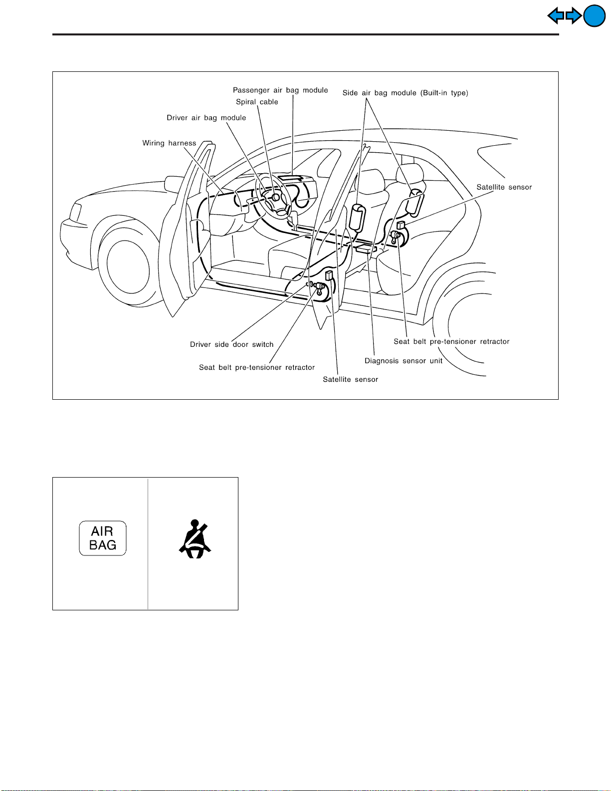
SUPPLEMENTAL RESTRAINT SYSTEM (SRS)
SRS Component Parts Location
EXIT
EXIT
SRS222
SRS768
Maintenance Items
CAUTION:
Do not use a circuit tester to check SRS circuit.
1. Check operation of “AIR BAG” and “SEAT BELT” warning
lamps.
After turning ignition key to “ON” position, both warning lamps
illuminate. The “AIR BAG” warning lamp will go off after about
7 seconds if no malfunction is detected. The “SEAT BELT”
warning lamp will also go off after about 7 seconds after seat
belt has been fastened and no malfunction is detected. (When
seat belt has not been fastened, the warning lamp continues
to illuminate until seat belt is fastened.)
If any of the following warning lamp conditions occur, immediately check the air bag or seat belt pre-tensioner system. Refer
to RS-38 or RS-39 for details.
! The “AIR BAG” or “SEAT BELT” warning lamp does not illumi-
nate when the ignition switch is turned “ON”.
! The “AIR BAG” or “SEAT BELT” (with seat belt fastened) warn-
ing lamp does not go off about 7 seconds after the ignition
switch is turned “ON”.
! The “AIR BAG” or “SEAT BELT” (with seat belt fastened) warn-
ing lamp blinks after about 7 seconds after the ignition switch
is turned “ON”.
RS-14
Page 60

SUPPLEMENTAL RESTRAINT SYSTEM (SRS)
Maintenance Items (Cont’d)
2. Visually check SRS components.
(1) Diagnosis sensor unit
! Check diagnosis sensor unit and bracket for dents, cracks and
deformities.
! Check connectors for damage and terminals for deformities.
(2) Air bag module and steering wheel
! Remove air bag module from steering wheel, instrument panel
or seatback. Check harness cover and connectors for damage,
terminals for deformities, and harness for binding.
! Install driver air bag module to steering wheel to check fit or
alignment with the wheel.
! Check steering wheel for excessive free play.
! Install passenger air bag module to instrument panel to check
fit or alignment with the instrument panel.
! Install side air bag module to seatback to check fit and align-
ment with the seat.
(3) Spiral cable
! Check spiral cable for dents, cracks and deformities.
! Check connectors and protective tape for damage.
! Check steering wheel for noise, binding and heavy operation.
GI
MA
EM
LC
EC
FE
EXIT
EXIT
(4) Main harness, air bag harness, body harness, side air bag
module sub-harness
! Check connectors for poor connections, damage, and termi-
nals for deformities.
! Check harnesses for binding, chafing and cuts.
(5) Seat belt pre-tensioner
! Check harness cover and connectors for damage, terminals
for deformities, and harness for binding.
! Check belts for damage and anchors for loose mounting.
! Check retractor for smooth operation.
! Perform self-diagnosis for seat belt pre-tensioner using seat
belt warning lamp or CONSULT-II. Refer to “Self-diagnosis” for
details. (RS-39)
(6) Satellite sensor
! Check satellite sensor (including bracket portion) for dents,
cracks or deformities.
! Check connectors for damage, and terminals for deformities.
CAUTION:
Replace previously used special bolts and ground bolt with
new ones.
AT
PD
FA
RA
BR
ST
BT
HA
RS-15
EL
IDX
Page 61

SUPPLEMENTAL RESTRAINT SYSTEM (SRS)
Removal and Installation — Diagnosis Sensor
Unit, Seat Belt Pre-tensioner and Satellite
Sensor
CAUTION:
! Before servicing SRS, turn the ignition switch off, disconnect both battery cables and wait at least
3 minutes.
! The special bolts are coated with bonding agent while the other bolt is for ground. Do not use old
bolts after removal; replace with new ones.
! Check diagnosis sensor unit, seat belt pre-tensioner and satellite sensor for proper installation.
! Check diagnosis sensor unit and satellite sensor to ensure they are free of deformities, dents,
cracks or rust. If they show any visible signs of damage, replace them with new ones.
! Check diagnosis sensor unit brackets to ensure they are free of deformities and rust.
! After replacement of diagnosis sensor unit, seat belt pre-tensioner and satellite sensor, check SRS
function and perform self-diagnosis for SRS. Refer to “Self-diagnosis” for details. (RS-38)
! Do not attempt to disassemble diagnosis sensor unit, seat belt pre-tensioner and satellite sensor.
! Replace diagnosis sensor unit, seat belt pre-tensioner and satellite sensor if it has been dropped
or sustained an impact.
! Do not expose seat belt pre-tensioner to temperatures exceeding 80°C (176°F).
EXIT
EXIT
SRS323-A
REMOVAL OF DIAGNOSIS SENSOR UNIT
1. Disconnect driver, passenger and side air bag module connectors. Also, disconnect seat belt pre-tensioner connector.
2. Remove console box. Refer to BT section, “INSTRUMENT
PANEL”.
3. Disconnect diagnosis sensor unit connector.
4. Remove ground bolt and also remove special bolts using the
TAMPER RESISTANT TORX (Size T50), from diagnosis sensor unit.
Then remove the diagnosis sensor unit.
NOTE:
! To install, reverse the removal procedure sequence.
REMOVAL OF SEAT BELT PRE-TENSIONER
For removal of seat belt pre-tensioner, refer to “Front Seat Belt” for
details. (RS-4)
NOTE:
! To install, reverse the removal procedure sequence.
SRS224-A
RS-16
Page 62
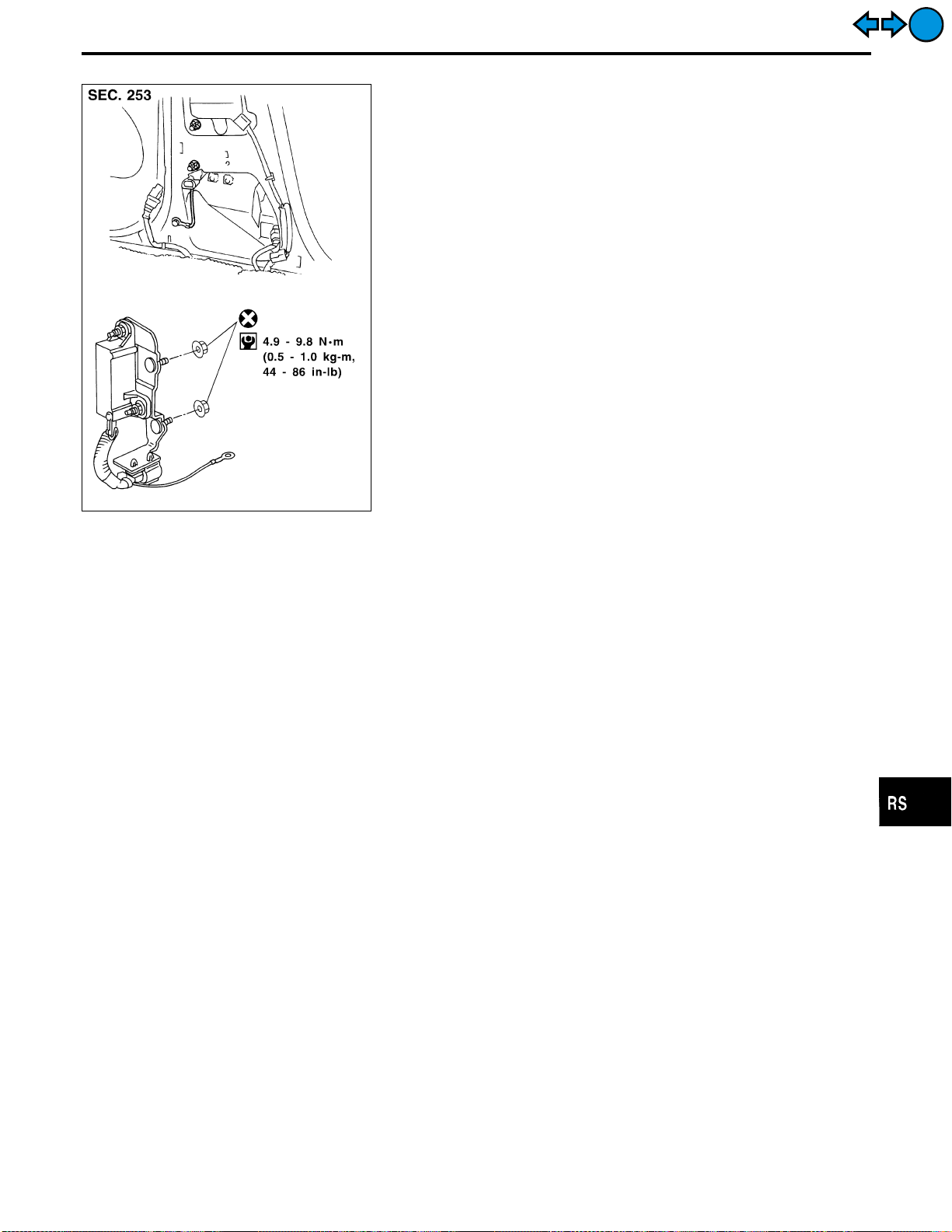
SUPPLEMENTAL RESTRAINT SYSTEM (SRS)
Removal and Installation — Diagnosis Sensor
Unit, Seat Belt Pre-tensioner and Satellite
Sensor (Cont’d)
REMOVAL OF SATELLITE SENSOR
1. Remove seat belt pre-tensioner. Refer to “REMOVAL OF SEAT
BELT PRE-TENSIONER” for details. (RS-16)
2. Disconnect satellite sensor connector.
3. Remove bolt and nuts from satellite sensor unit.
Then remove the satellite sensor.
NOTE:
! To install, reverse the removal procedure sequence.
GI
MA
EM
LC
EC
FE
EXIT
EXIT
SRS324-B
AT
PD
FA
RA
BR
ST
BT
HA
RS-17
EL
IDX
Page 63

SUPPLEMENTAL RESTRAINT SYSTEM (SRS)
Removal — Driver Air Bag Module and Spiral
Cable
EXIT
EXIT
SBF811E
SRS597-A
CAUTION:
! Before servicing SRS, turn the ignition switch off, discon-
nect both battery cables and wait at least 3 minutes.
! Always work from the side of air bag module.
1. Remove lower lid from steering wheel, and disconnect air bag
module connector.
2. Remove side lids, and remove ASCD switch and audio unit
steering switch (or TEL switch).
SBF812E
3. Using the TAMPER RESISTANT TORX (Size T50), remove left
and right special bolts. Air bag module can then be removed.
RS-18
Page 64

SUPPLEMENTAL RESTRAINT SYSTEM (SRS)
Removal — Driver Air Bag Module and Spiral
Cable (Cont’d)
CAUTION:
! Always place air bag module with pad side facing upward.
! Do not attempt to disassemble air bag module.
! The special bolts are coated with bonding agent. Do not
use old bolts after removal; replace with new ones.
! Do not insert any foreign objects (screwdriver, etc.) into
air bag module connector.
GI
MA
EXIT
EXIT
SRS226
SBF814E
SBF239F
! Replace air bag module if it has been dropped or sus-
tained an impact.
! Do not expose the air bag module to temperatures exceed-
ing 90°C (194°F).
! Do not allow oil, grease or water to come in contact with
the air bag module.
4. Set steering wheel in the neutral position.
5. Disconnect horn connector and remove nuts.
6. Remove dynamic damper. Then using steering wheel puller,
remove steering wheel. Be careful not to over-tighten puller
bolt on steering wheel.
CAUTION:
! Do not tap or bump the steering wheel.
7. Remove steering column cover.
EM
LC
EC
FE
AT
PD
FA
RA
BR
SRS384
SRS227
8. Unlock the spiral cable connector. Then disconnect connector
and remove the four screws. The spiral cable can then be
removed.
CAUTION:
! Do not attempt to disassemble spiral cable.
! Do not apply lubricant to the spiral cable.
Removal — Front Passenger Air Bag Module
CAUTION:
! Before servicing SRS, turn the ignition switch off, discon-
nect both battery cables and wait at least 3 minutes.
! Always work from the side of or under air bag module.
1. Remove lower instrument cover.
2. Remove connector bracket from air bag module and disconnect inflator connector from body harness air bag connector.
3. Remove glove box assembly. Refer to BT section, “INSTRUMENT PANEL” for details.
RS-19
ST
BT
HA
EL
IDX
Page 65

SUPPLEMENTAL RESTRAINT SYSTEM (SRS)
Removal — Front Passenger Air Bag Module
(Cont’d)
4. Remove special bolts from air bag module using TAMPER
RESISTANT TORX (Size T50).
5. Remove mounting bolts from back of instrument assembly.
6. Move air bag module upward, and remove it from instrument
assembly.
! The air bag module is heavy and should be supported using
both hands during removal.
SRS228-A
CAUTION:
! Always place air bag module with pad side facing upward.
! Do not attempt to disassemble air bag module.
! The special bolts are coated with bonding agent. Do not
use old bolts after removal; replace with new coated bolts.
! Do not insert any foreign objects (screwdriver, etc.) into
air bag module connector.
EXIT
EXIT
SRS229
SBF814E
! Replace air bag module if it has been dropped or sus-
tained an impact.
! Do not expose the air bag module to temperatures exceed-
ing 90°C (194°F).
! Do not allow oil, grease or water to come in contact with
the air bag module.
! After air bag inflates, the front instrument panel assembly
should be replaced if damaged.
Removal — Side Air Bag Module (Built-in type)
CAUTION:
! Before servicing SRS, turn the ignition switch off, discon-
nect both battery cables and wait at least 3 minutes.
! Always work from the rear of air bag module.
1. Remove seat back board.
! When using a clip removal tool to remove the seat back
board, take care not to damage the air bag harness.
2. Disconnect side air bag module connector.
SRS325
RS-20
Page 66

SUPPLEMENTAL RESTRAINT SYSTEM (SRS)
Removal — Side Air Bag Module (Built-in type)
(Cont’d)
GI
MA
EM
LC
EC
FE
EXIT
EXIT
SRS573
SRS809
3. Pull up the seat back trim.
4. Remove the nuts securing the inner cloth which covers side air
bag module. Then pull up the inner cloth.
5. Remove the screws securing the seat back finisher. Then
remove the seat back finisher.
6. Remove the torx nuts coated with bonding agent from side air
bag module.
7. Remove harness clips. Side air bag module can then be
removed.
CAUTION:
! Always place the air bag module with the stud bolt side
facing down.
! Do not attempt to disassemble air bag module.
! The torx nuts are coated with bonding agent. Do not use
old nuts after removal; replace with new coated nuts.
! Do not insert any foreign objects (screwdriver, etc.) into
air bag module connector.
! Replace air bag module if it has been dropped or sus-
tained an impact.
! Do not expose the air bag module to temperatures exceed-
ing 90°C (194°F).
! Do not allow oil, grease or water to come in contact with
the air bag module.
! After air bag inflates, all parts of front seat back (includ-
ing front seat back frame) should be replaced.
AT
PD
FA
RA
BR
ST
BT
HA
EL
IDX
SBF814E
RS-21
Page 67

SUPPLEMENTAL RESTRAINT SYSTEM (SRS)
Installation — Driver Air Bag Module and Spiral
Cable
1. Set the front wheels in the straight-ahead position.
2. Make sure that the spiral cable is in the neutral position.
The neutral position is detected by turning left about 2.5 revolutions from the right end position. Align the two marks (
CAUTION:
! The spiral cable may snap due to steering operation if the
cable is installed in an improper position.
Also, with the steering linkage disconnected, the cable
may snap by turning the steering wheel beyond the limited
number of turns.
The spiral cable can be turned up to about 2.5 turns from
the neutral position to both the right and left.
3. Connect and lock spiral cable connector and tighten with
screws. Install steering column cover.
EXIT
EXIT
#
).
$
SRS358
SRS231
SBF812EH
4. Install steering, wheel setting spiral cable pin guide, and pull
spiral cable through.
5. Connect horn connector and engage spiral cable with pawls in
steering wheel. Move air bag module connector away from
steering wheel lower lid opening.
6. Tighten nut.
: 29.4 - 39.2 N⋅m (3.0 - 4.0 kg-m, 22 - 28 ft-lb)
7. Install dynamic damper.
8. Position air bag module and tighten with new special bolts.
! Always service the air bag module from the side.
9. Connect air bag module connector.
10. Install steering switches and lid.
11. Go to “Self-diagnosis”, RS-38 and perform self-diagnosis to
ensure entire SRS operates properly. (Use CONSULT-II or
warning lamp check.)
Before performing self-diagnosis, connect both battery cables.
12. Turn steering wheel to the left end and then to the right end
fully to make sure that spiral cable is set in the neutral position.
If air bag warning lamp blinks or stays ON (at the User
mode), it shows the spiral cable may be snapped due to its
improper position. Perform self-diagnosis again (use CONSULT-II or warning lamp). If a malfunction is detected, replace
the spiral cable with a new one.
13. Perform self-diagnosis again to check that no malfunction is
detected.
RS-22
Page 68

SUPPLEMENTAL RESTRAINT SYSTEM (SRS)
Installation — Front Passenger Air Bag Module
! Always work from the side of or under air bag module.
1. Install front passenger air bag module on steering member.
! Ensure harness is not caught between rear of air bag module
and steering member.
2. Install glove box assembly. (Glove box lid is open.)
GI
MA
EXIT
EXIT
SRS228-A
SRS227
3. Connect air bag module connector to body harness connector.
4. Install lower instrument cover on instrument panel assembly.
5. Connect both battery cables.
6. Go to “Self-diagnosis”, RS-38 and perform self-diagnosis to
ensure entire SRS operates properly. (Use CONSULT-II or
warning lamp.)
Installation — Side Air Bag Module (Built-in
type)
EM
LC
EC
FE
AT
PD
FA
RA
BR
SRS809
1. Install side air bag module on front seat with new torx nuts
coated with bonding agent.
2. Secure the side air bag module harness with new harness
clips.
3. Install the seat back finisher with screws.
4. Secure the inner cloth which covers the side air bag module
and seat back finisher with nuts.
RS-23
ST
BT
HA
EL
IDX
Page 69

SUPPLEMENTAL RESTRAINT SYSTEM (SRS)
Installation — Side Air Bag Module (Built-in
type) (Cont’d)
5. Connect side air bag module connector.
6. Install seat back board with new clips.
! Ensure harness is not caught between seat back board
and seat back.
7. Connect both battery cables.
8. Go to “Self-diagnosis”, RS-38 and perform self-diagnosis to
ensure entire SRS operates properly. (Use CONSULT-II or air
bag warning lamp.)
EXIT
EXIT
SRS328
Disposal of Air Bag Module and Seat Belt
Pre-tensioner
! Before disposing of air bag module and seat belt pre-tensioner, or vehicles equipped with such systems,
deploy the systems. If such systems have already been deployed due to an accident, dispose of them as
indicated in “DISPOSING OF AIR BAG MODULE AND SEAT BELT PRE-TENSIONER” (RS-29).
! When deploying the air bag module and seat belt pre-tensioner, always use the Special Service Tool;
Deployment tool KV99106400 (Kent-Moore No. J38381).
! When deploying the air bag module and seat belt pre-tensioner, stand at least 5 m (16 ft) away from the
deployment component.
! When deploying air bag module and seat belt pre-tensioner, a fairly loud noise is made, followed by smoke
being released. The smoke is not poisonous, however, be careful not to inhale smoke since it irritates the
throat and can cause choking.
! Always activate one air bag module at a time.
! Due to heat, leave air bag module unattended for more than 30 minutes after deployment. Also leave seat
belt pre-tensioner unattended for move than 10 minutes after deployment.
! Be sure to wear gloves when handling a deployed air bag module and seat belt pre-tensioner.
! Never apply water to the deployed air bag module and seat belt pre-tensioner.
! Wash your hands clean after finishing work.
! Place the vehicle outdoors with an open space of at least 6 m (20 ft) on all sides when deploying air bag
module and seat belt pre-tensioner while mounted in vehicle.
! Use a voltmeter to make sure the vehicle battery is fully charged.
! Do not dispose of the air bag module and seat belt pre-tensioner un-deployed.
RS-24
Page 70

SUPPLEMENTAL RESTRAINT SYSTEM (SRS)
Disposal of Air Bag Module and Seat Belt
Pre-tensioner (Cont’d)
CHECKING DEPLOYMENT TOOL
Connecting to battery
CAUTION:
The battery must show voltage of 9.6V or more.
Remove the battery from the vehicle and place it on dry wood
blocks approximately 5 m (16 ft) away from the vehicle.
! Wait 3 minutes after the vehicle battery is disconnected before
proceeding.
SRS005-A
! Connect red clip of deployment tool to battery positive termi-
nal and black clip to negative terminal.
Make sure the polarity is correct. The right side lamp in the
tool, marked “deployment tool power”, should glow with a
green light. If the right side lamp glows red, reverse the connections to the battery.
GI
MA
EM
LC
EC
FE
EXIT
EXIT
SBF266H
Deployment tool check
Press the deployment tool switch to the “ON” position. The left side
lamp in the tool, marked “air bag connector voltage” should illuminate. If it does not illuminate, replace the tool.
Air bag deployment tool lamp illumination chart
(Battery connected)
Left side lamp, green*
Switch operation
OFF OFF ON
ON ON ON
*: If this lamp glows red, the tool is connected to the battery incorrectly.
Reverse the connections and make sure the lamp glows green.
“AIR BAG CONNECTOR
VOLTAGE”
Right side lamp, green*
“DEPLOYMENT TOOL
POWER”
AT
PD
FA
RA
BR
ST
BT
HA
RS-25
EL
IDX
Page 71

SUPPLEMENTAL RESTRAINT SYSTEM (SRS)
Disposal of Air Bag Module and Seat Belt
Pre-tensioner (Cont’d)
DEPLOYMENT PROCEDURES FOR AIR BAG MODULE
(OUTSIDE OF VEHICLE)
Unless the vehicle is being scrapped, deploying the air bag in the
vehicle is not recommended. This may cause damage to the
vehicle interior.
Anchor air bag module bracket [KV99105300 (J41246)] in a vise
secured to a firm foundation during deployment.
EXIT
EXIT
SRS232-C
SRS233
SRS234
Deployment of driver’s air bag module (outside of
vehicle)
1. Using wire, secure air bag module to air bag module bracket
[SST: KV99105300 (J41246)] at two places.
CAUTION:
Use wire of at least 1 mm (0.04 in) diameter.
2. Firmly secure air bag module bracket [SST: KV99105300
(J41246)] with air bag module attached, in a vise.
3. Connect deployment tool [SST: KV99106400 (J38381)] to air
bag module connector.
SRS235
SRS236
4. Connect red clip of deployment tool to battery positive terminal and black clip to negative terminal.
5. The lamp on the right side of the tool, marked “deployment tool
power”, should glow green, not red.
6. Press the button on the deployment tool. The left side lamp on
the tool, marked “air bag connector voltage”, will illuminate and
the air bag module will deploy.
CAUTION:
When deploying the air bag module, stand at least 5 m (16 ft)
away from the air bag module.
Deployment of passenger air bag module (outside of
vehicle)
1. Make an 8.5 mm (0.335 in) diameter hole in air bag module
bracket [SST: KV99105300 (J41246)] at the position shown in
figure at left.
RS-26
Page 72

SUPPLEMENTAL RESTRAINT SYSTEM (SRS)
Disposal of Air Bag Module and Seat Belt
Pre-tensioner (Cont’d)
2. Firmly secure air bag module bracket [SST: KV99105300
(J41246)] in a vise.
3. Match the two holes in air bag module bracket (held in vise)
and passenger air bag module and fix them with two bolts [M8
x 25 - 30 mm (0.98 - 1.18 in)].
CAUTION:
If a gap exists between passenger air bag module and air bag
module bracket, use a piece of wood inserted in the gap to
stabilize the air bag module.
SRS237
4. Connect deployment tool adapter [SST: KV991065S0 (J38381-
30)] to deployment tool [SST: KV99106400 (J38381)] connector and connector of air bag module.
5. Connect red clip of deployment tool to battery positive terminal and black clip to negative terminal.
6. The lamp on the right side of the tool, marked “deployment tool
power”, should glow green, not red.
7. Press the button on the deployment tool. The left side lamp on
the tool, marked “air bag connector voltage”, will illuminate and
the air bag module will deploy.
SRS239
CAUTION:
When deploying the air bag module, stand at least 5 m (16 ft)
away from the air bag module.
GI
MA
EM
LC
EC
FE
AT
PD
EXIT
EXIT
SRS490-A
Deployment of side air bag module (Built-in type)
(outside of vehicle)
1. Make 6.5 mm (0.256 in) diameter holes in air bag module
bracket [SST: KV99105300 (J41246)] at the position shown in
figure at left.
2. Firmly secure air bag module bracket [SST: KV99105300
(J41246)] in a vise.
3. Insert the stud bolts of side air bag module (built-in type) into
the two holes in air bag module bracket (held in vise) and fix
them with two M6 nuts.
CAUTION:
Side air bag module should be secured to air bag module
bracket [SST: KV99105300 (J41246)] in a vise with metal portion facing down.
FA
RA
BR
ST
BT
HA
EL
IDX
SRS491-A
RS-27
Page 73

SUPPLEMENTAL RESTRAINT SYSTEM (SRS)
Disposal of Air Bag Module and Seat Belt
Pre-tensioner (Cont’d)
4. Connect deployment tool [SST: KV99106400 (J38381)] to side
air bag module connector.
5. Connect red clip of deployment tool to battery positive terminal and black clip to negative terminal.
6. The lamp on the right side of the tool, marked “deployment tool
power”, should glow green, not red.
7. Press the button on the deployment tool. The left side lamp on
the tool, marked “air bag connector voltage”, will illuminate and
the air bag module will deploy.
SRS020-B
CAUTION:
When deploying the air bag module, stand at least 5 m (16 ft)
away from the air bag module.
EXIT
EXIT
SRS810
SRS811
SRS242
Deployment of seat belt pre-tensioner (outside of
vehicle)
1. Firmly grip pre-tensioner in a vise and cut the webbing off.
2. Connect deployment tool adapter [SST: KV99108200 (J38381-
50)] to deployment tool [SST: KV99106400 (J38381)] connector and seat belt pre-tensioner connector.
3. Connect red clip of deployment tool to battery positive terminal and black clip to negative terminal.
4. The lamp on the right side of the tool, marked “deployment tool
power”, should glow green, not red.
5. Press the button on the deployment tool. The left side lamp on
the tool, marked “seat belt pre-tensioner connector voltage”,
will illuminate and the seat belt pre-tensioner will deploy.
CAUTION:
When deploying the seat belt pre-tensioner, stand at least 5 m
(16 ft) away from the seat belt pre-tensioner.
RS-28
Page 74

SUPPLEMENTAL RESTRAINT SYSTEM (SRS)
Disposal of Air Bag Module and Seat Belt
Pre-tensioner (Cont’d)
DEPLOYMENT OF AIR BAG MODULE AND SEAT BELT
PRE-TENSIONER WHILE MOUNTED IN VEHICLE
When disposing of a vehicle, deploy air bag modules and seat belt
pre-tensioners while they are mounted in vehicle.
CAUTION:
When deploying air bag module or seat belt pre-tensioner,
ensure vehicle is empty.
1. Disconnect both vehicle battery cables and wait 3 minutes.
SRS006-A
2. Disconnect air bag modules and seat belt pre-tensioners connector.
3. Connect deployment tool [SST: KV99106400 (J38381)] to air
bag module or seat belt pre-tensioner.
For front passenger air bag module, attach deployment tool
adapter [SST: KV991065S0 (J38381-30)] to the tool connector.
For seat belt pre-tensioner, attach deployment tool adapter
[SST: KV99108200 (J38381-50)] to the tool connector.
4. Connect red clip of deployment tool to battery positive terminal and black clip to negative terminal.
5. The lamp on the right side of the tool, marked “deployment tool
power”, should glow green, not red.
6. Press the button on the deployment tool. The left side lamp on
the tool, marked “air bag connector voltage”, will illuminate and
the air bag module or seat belt pre-tensioner will deploy.
CAUTION:
Activate only one air bag module or seat belt pre-tensioner at
a time.
GI
MA
EM
LC
EC
FE
AT
PD
FA
EXIT
EXIT
SBF276H
DISPOSING OF AIR BAG MODULE AND SEAT BELT
PRE-TENSIONER
Deployed air bag modules and seat belt pre-tensioners are very
hot. Before disposing of air bag module, and seat belt pretensioner, wait at least 30 minutes, and 10 minutes, respectively.
Seal them in a plastic bag before disposal.
CAUTION:
! Never apply water to a deployed air bag module and seat
belt pre-tensioner.
! Be sure to wear gloves when handling a deployed air bag
module and seat belt pre-tensioner.
! No poisonous gas is produced upon air bag module
deployment. However, be careful not to inhale gas since it
irritates throat and can cause choking.
! Do not attempt to disassemble air bag module and seat
belt pre-tensioner.
! Air bag module and seat belt pre-tensioner cannot be re-
used.
! Wash your hands clean after finishing work.
RA
BR
ST
BT
HA
EL
IDX
RS-29
Page 75

TROUBLE DIAGNOSES — Supplemental Restraint System (SRS)
Trouble Diagnoses Introduction
CAUTION:
! Do not use electrical test equipment to check SRS harness connectors unless instructed to in this
Service Manual. Spiral cable and wiring harnesses (except satellite sensor and side air bag module) covered with yellow insulation tape either just before the harness connectors or for the complete harness are related to the SRS.
! Do not attempt to repair, splice or modify the SRS wiring harness. If the harness is damaged,
replace it with a new one.
! Keep ground portion clean.
DIAGNOSIS FUNCTION
The SRS self-diagnosis results can be read by using “AIR BAG” warning lamp, “SEAT BELT” warning lamp
and/or CONSULT-II. The reading of these results is accomplished using one of two modes — “User mode”
and “Diagnosis mode”.
The User mode is exclusively prepared for the customer (driver). This mode warns the driver of a system
malfunction through the operation of the “AIR BAG” warning lamp and/or “SEAT BELT” warning lamp.
The Diagnosis mode allows the technician to locate and inspect the malfunctioning part.
The mode applications for the “AIR BAG” warning lamp, “SEAT BELT” warning lamp and CONSULT-II are as
follows:
User mode Diagnosis mode Display type
“AIR BAG” warning lamp X X ON-OFF operation
“SEAT BELT” warning lamp X — ON-OFF operation
CONSULT-II — X Monitoring
EXIT
EXIT
DIAGNOSIS MODE FOR CONSULT-II
! “SELF-DIAG [CURRENT]”
A current Self-diagnosis result (also indicated by the warning lamp flashes in the Diagnosis mode) is displayed on the CONSULT-II screen in real time. This refers to a malfunctioning part requiring repairs.
! “SELF-DIAG [PAST]”
Diagnosis results previously stored in the memory (also indicated by the warning lamp flashes in the
Diagnosis mode) are displayed on the CONSULT-II screen. The stored results are not erased until memory
erasing is executed.
! “TROUBLE DIAG RECORD”
With TROUBLE DIAG RECORD, diagnosis results previously erased by a reset operation can be displayed
on the CONSULT-II screen.
! “ECU DISCRIMINATED NO.”
The diagnosis sensor unit for each vehicle model is assigned
with its own, individual classification number. This number will
be displayed on the CONSULT-II screen, as shown at left.
When replacing the diagnosis sensor unit, refer to the part
number for the compatibility. After installation, replacement
with a correct unit can be checked by confirming this classification number on the CONSULT-II screen.
For INFINITI Q45, the diagnosis sensor unit classification
number assigned is 2E.
SRS752
RS-30
Page 76

TROUBLE DIAGNOSES — Supplemental Restraint System (SRS)
Trouble Diagnoses Introduction (Cont’d)
HOW TO CHANGE SELF-DIAGNOSIS MODE
With CONSULT-II
From User mode to Diagnosis mode
After selecting AIR BAG on the “SELECT SYSTEM” screen, User mode automatically changes to Diagnosis
mode.
GI
MA
EM
LC
EXIT
EXIT
SRS769
From Diagnosis mode to User mode
To return to User mode from Diagnosis mode, touch “BACK” key of CONSULT-II until “SELECT SYSTEM”
appears, Diagnosis mode automatically changes to User mode.
SRS770
Without CONSULT-II
From User mode to Diagnosis mode
Diagnosis mode activates only when a malfunction is detected, by
pressing the driver’s door switch at least 5 times within 7 seconds
after turning the ignition “ON”. SRS will not enter Diagnosis mode
if no malfunction is detected.
EC
FE
AT
PD
FA
RA
BR
ST
BT
SRS247
From Diagnosis mode to User mode
After a malfunction is repaired, switch the ignition “OFF” for at least 1 second, then back “ON”. Diagnosis mode
returns to User mode.
If switching from Diagnosis mode to User mode is required while malfunction is being detected, switch the
ignition “OFF”, then back “ON” and press the driver’s door switch at least 5 times within 7 seconds.
RS-31
HA
EL
IDX
Page 77
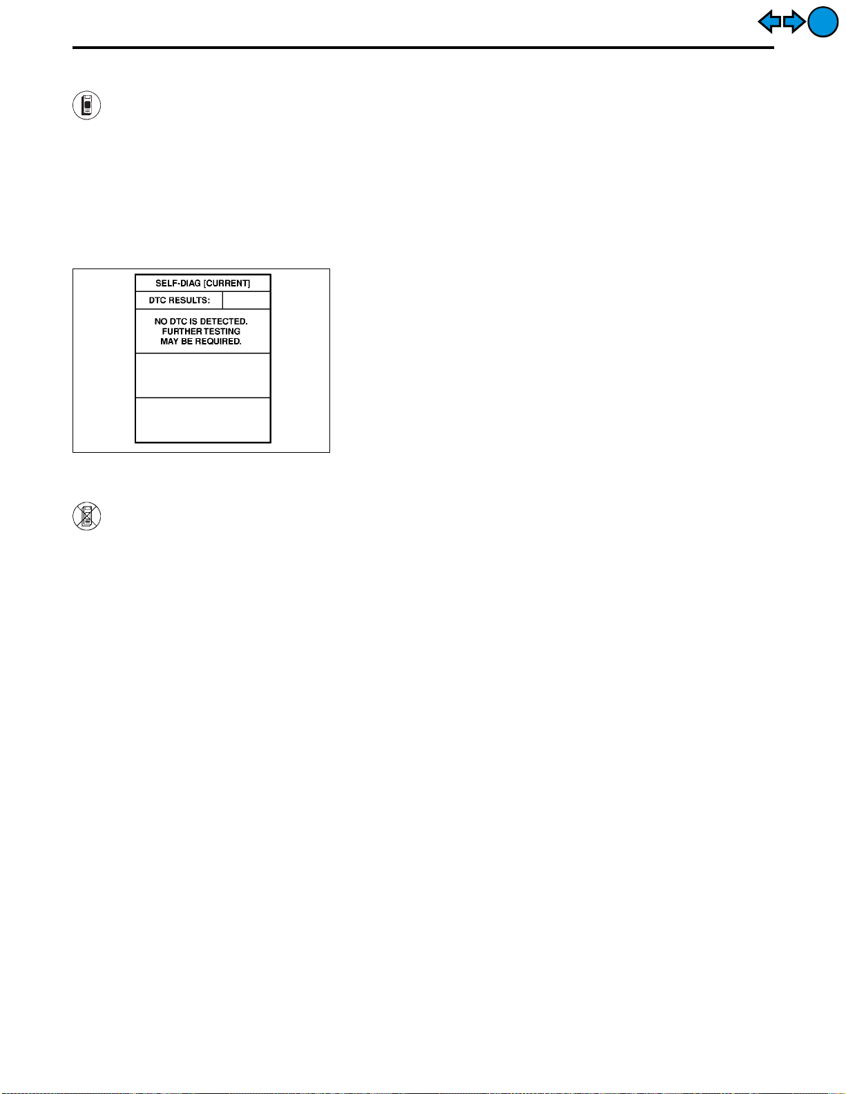
TROUBLE DIAGNOSES — Supplemental Restraint System (SRS)
Trouble Diagnoses Introduction (Cont’d)
HOW TO ERASE SELF-DIAGNOSIS RESULTS
With CONSULT-II
! “SELF-DIAG [CURRENT]”
A current self-diagnosis result is displayed on the CONSULT-II screen in real time. After the malfunction
is repaired completely, no malfunction is detected on “SELF-DIAG [CURRENT]”.
! “SELF-DIAG [PAST]”
Return to the “SELF-DIAG [CURRENT]” CONSULT-II screen by
pushing “BACK” key of CONSULT-II and select “SELF-DIAG [CURRENT]” in “SELECT DIAG MODE”. Touch “ERASE” in “SELF-DIAG
[CURRENT]” mode.
NOTE:
If the memory of the malfunction in “SELF-DIAG [PAST]” is not
erased, the User mode shows the system malfunction by the
operation of the warning lamp even if the malfunction is
repaired completely.
SRS701
EXIT
EXIT
! “TROUBLE DIAG RECORD”
The memory of TROUBLE DIAG RECORD cannot be erased.
Without CONSULT-II
After a malfunction is repaired, return from Diagnosis mode to User mode by switching the ignition “OFF” for
at least 1 second, then back “ON”. At that time, the self-diagnosis result is cleared.
How to Perform Trouble Diagnoses for Quick
and Accurate Repair
A good understanding of the malfunction conditions can make troubleshooting faster and more accurate.
In general, each customer feels differently about a malfunction. It is important to fully understand the symptoms or conditions for a customer complaint.
INFORMATION FROM CUSTOMER
WHAT ............ Vehicle model
WHEN ........... Date, Frequencies
WHERE ......... Road conditions
HOW .............. Operating conditions, Symptoms
PRELIMINARY CHECK
Check that the following parts are in good order.
! Battery (Refer to EL section, “BATTERY”.)
! Fuse (Refer to EL section, “Fuse”, “POWER SUPPLY ROUTING”.)
! System component-to-harness connections
RS-32
Page 78

TROUBLE DIAGNOSES — Supplemental Restraint System (SRS)
WORK FLOW
Listen to customer complaints and requests.
How to Perform Trouble Diagnoses for Quick
and Accurate Repair (Cont’d)
ACTION ITEM REFERENCE ITEM
Check in
'
GI
MA
EM
EXIT
EXIT
'
Perform preliminary check.
'
Check for any Service Bulletin.
'
Perform self-diagnosis using “AIR BAG” warning lamp and/or “SEAT
BELT” warning lamp. — User mode
'
Inspect malfunctioning part. — Diagnosis mode
&
Perform self-diagnosis using CONSULT-II.
---------------------------------------------------------------------------------------------------------------------------------------------------------------------------------------------------------------------------------- OR ---------------------------------------------------------------------------------------------------------------------------------------------------------------------------------------------------------------------------------Perform self-diagnosis using “AIR BAG” warning lamp.
'
Repair/Replace
NG
Final check — Diagnosis mode and User mode
CONSULT-II can only show one seat belt pre-tensioner malfunction as
self-diagnosis result at a time. Check self-diagnosis result with CONSULT-II whether other malfunctions are detected after repairing one
seat belt pre-tensioner malfunction.
'
OK
'
Check out
%
Preliminary check (RS-32)
LC
EC
FE
%
DIAGNOSTIC PROCEDURE 1
(RS-38)
AT
PD
%
DIAGNOSTIC PROCEDURE 2:
Using CONSULT-II (RS-40)
DIAGNOSTIC PROCEDURE 3:
Using “AIR BAG” warning lamp
(RS-44)
FA
RA
BR
ST
%
DIAGNOSTIC PROCEDURE 4:
Using CONSULT-II (RS-48)
DIAGNOSTIC PROCEDURE 5:
Using “AIR BAG” warning lamp
(RS-50)
BT
HA
RS-33
EL
IDX
Page 79

TROUBLE DIAGNOSES — Supplemental Restraint System (SRS)
Schematic
EXIT
EXIT
RS-34
TRS001M
Page 80

TROUBLE DIAGNOSES — Supplemental Restraint System (SRS)
Wiring Diagram — SRS —
GI
MA
EM
LC
EC
FE
EXIT
EXIT
AT
PD
FA
RA
BR
ST
BT
HA
RS-35
EL
IDX
TRS003M
Page 81

TROUBLE DIAGNOSES — Supplemental Restraint System (SRS)
Wiring Diagram — SRS — (Cont’d)
EXIT
EXIT
RS-36
TRS004M
Page 82

TROUBLE DIAGNOSES — Supplemental Restraint System (SRS)
Wiring Diagram — SRS — (Cont’d)
GI
MA
EM
LC
EC
FE
EXIT
EXIT
AT
PD
FA
RA
BR
ST
BT
HA
RS-37
EL
IDX
TRS098
Page 83

TROUBLE DIAGNOSES — Supplemental Restraint System (SRS)
Self-diagnosis
DIAGNOSTIC PROCEDURE 1
Checking SRS operation by using “AIR BAG” warning lamp —
User mode
1. After turning ignition switch from “OFF” to “ON”, “AIR BAG”
warning lamp operates.
2. Compare “AIR BAG” warning lamp operation to the chart
below.
SRS244
“AIR BAG” warning lamp operation — User mode — SRS condition Reference item
No malfunction is
detected.
No further action is necessary.
—
MRS095A
EXIT
EXIT
MRS096A
MRS097A
MRS098A
The system is malfunctioning and needs to be
repaired as indicated.
Air bag (and seat belt pretensioner) is deployed.
Air bag fuse, diagnosis
sensor unit or harness is
malfunctioning and needs
to be repaired.
One of the following has
occurred and needs to be
repaired.
! Meter fuse is blown.
! “AIR BAG” warning lamp
circuit has open or short.
! Diagnosis sensor unit is
malfunctioning.
Go to DIAGNOSTIC PROCEDURE 2 or 3 (RS-40 or
44).
Go to COLLISION DIAGNOSIS (RS-60).
Go to DIAGNOSTIC PROCEDURE 9 (RS-56).
Go to DIAGNOSTIC PROCEDURE 10 (RS-56).
NOTE:
If “AIR BAG” warning lamp operates differently from the
operations shown above, refer to “AIR BAG” warning lamp
operation — Diagnosis mode —, DIAGNOSTIC PROCEDURE 3
(step 4), RS-44.
RS-38
Page 84

TROUBLE DIAGNOSES — Supplemental Restraint System (SRS)
Self-diagnosis (Cont’d)
Checking seat belt pre-tensioner operation by using “SEAT
BELT” warning lamp — User mode
1. After turning ignition switch from “OFF” to “ON”, “SEAT BELT”
warning lamp operates.
2. Compare “SEAT BELT” warning lamp operation to the chart
below.
GI
MA
EXIT
EXIT
SRS245
“SEAT BELT” warning lamp operation SRS condition Reference item
! After driver’s seat belt has been fastened.
! When driver’s seat belt has not been fastened.
! After driver’s seat belt has been fastened.
! When driver’s seat belt has not been fastened.
! When driver’s seat belt is fastened.
MRS095A
SRS086
MRS096A
SRS344
MRS097A
No malfunction is
detected.
No further action is necessary.
! Seat belt pre-tensioner
circuit is opened, or
! Seat belt pre-tensioner
power supply or ground
circuit is shorted.
Seat belt pre-tensioner
(and air bag) is deployed.
Seat belt buckle switch,
harness, combination
meter assembly, diagnosis
sensor unit are malfunctioning and need to be
repaired.
Meter fuse, diagnosis sensor unit or “SEAT BELT”
warning lamp circuit is
shorted or open and needs
to be repaired.
—
! If CONSULT-II is
available, go to DIAGNOSTIC PROCEDURE
2 (RS-40).
! If CONSULT-II is not
available, repair the system as follows.*
1. Visually check the wiring harness connections.
2. Replace the harness if
it has visible damage.
3. Replace driver’s and
front passenger seat
belt assemblies.
(Before disposing, they
must be deactivated.)
4. Replace diagnosis sensor unit.
Go to COLLISION DIAGNOSIS (RS-60).
Go to DIAGNOSTIC PROCEDURE 12 (RS-58).
Go to DIAGNOSTIC PROCEDURE 13 (RS-59).
EM
LC
EC
FE
AT
PD
FA
RA
BR
ST
BT
HA
EL
IDX
MRS098A
* Follow the procedures in numerical order when repairing malfunctioning parts. Confirm whether malfunction is eliminated
using the seat belt warning lamp each time repair is finished. If malfunction is still observed, proceed to the next step. When
malfunction is eliminated, further repair work is not required.
RS-39
Page 85

TROUBLE DIAGNOSES — Supplemental Restraint System (SRS)
Self-diagnosis (Cont’d)
DIAGNOSTIC PROCEDURE 2 ( with CONSULT-II)
Inspecting SRS malfunctioning parts by using CONSULT-II —
Diagnosis mode
1. Turn ignition switch “OFF”.
2. Connect “CONSULT-II” to Data link connector.
SEF046TA
3. Turn ignition switch “ON”.
4. Touch “START”.
EXIT
EXIT
SRS695
SRS771
SRS697
5. Touch “AIR BAG”.
6. Touch “SELF-DIAG [CURRENT]”.
SRS772
7. Diagnostic codes are displayed on “SELF-DIAG [CURRENT]”.
RS-40
Page 86

TROUBLE DIAGNOSES — Supplemental Restraint System (SRS)
Self-diagnosis (Cont’d)
If no malfunction is detected on “SELF-DIAG [CURRENT]” but malfunction is indicated by the “AIR BAG” warning lamp, go to DIAGNOSTIC PROCEDURE 6, page RS-52, to diagnose the following
situations:
! Self-diagnostic result “SELF-DIAG [PAST]” (previously stored
in the memory) might not be erased after repair.
! The SRS system malfunctions intermittently.
GI
MA
EXIT
EXIT
SRS701
8. Touch “PRINT”.
9. Compare diagnostic codes to the CONSULT-II DIAGNOSTIC
CODE CHART, page RS-41.
10. Touch “BACK” key of CONSULT-II until “SELECT SYSTEM”
appears in order to return to User mode from Diagnosis mode.
11. Turn ignition switch “OFF”, then turn off and disconnect CONSULT-II and disconnect both battery cables.
12. Repair the system as outlined by the “Repair order” in CONSULT-II DIAGNOSTIC CODE CHART, that corresponds to the
self-diagnosis result. For replacement procedure of component
parts, refer to RS-16.
13. After repairing the system, go to DIAGNOSTIC PROCEDURE
4 for final checking, page RS-48.
CONSULT-II can only show one seat belt pre-tensioner malfunction as self-diagnosis result at a time. Check self-diagnosis result with CONSULT-II whether other malfunctions are
detected after repairing one seat belt pre-tensioner malfunction.
CONSULT-II DIAGNOSTIC CODE CHART (“SELF-DIAG [CURRENT]”)
Diagnostic item Explanation
NO DTC IS DETECTED When malfunction is indicated
AIRBAG MODULE
[OPEN]
AIRBAG MODULE
[VB-SHORT]
AIRBAG MODULE
[GND-SHORT]
AIRBAG MODULE
[SHORT]
by the “AIR BAG” warning lamp
in User mode
! No malfunction is detected. ! Go to DIAGNOSTIC PROCE-
! Driver’s air bag module circuit is open. (including the spiral cable) 1. Visually check the wiring har-
! Driver’s air bag module circuit is shorted to some power supply
circuit. (including the spiral cable)
! Driver’s air bag module circuit is shorted to ground. (including the
spiral cable)
! Driver’s air bag module circuits are shorted to each other.
! Self-diagnostic result “SELF-
DIAG [PAST]” (previously
stored in the memory) might
not be erased after repair.
! Intermittent malfunction has
been detected in the past.
Repair order
Recheck SRS at each
replacement.
! Go to DIAGNOSTIC PROCE-
DURE 6 (RS-52).
DURE 4 (RS-48).
ness connection.
2. Replace the harness if it has
visible damage.
3. Replace the spiral cable.
4. Replace driver’s air bag module.
(Before disposal of it, it must
be deployed.)
5. Replace the diagnosis sensor
unit.
6. Replace the related harness.
EM
LC
EC
FE
AT
PD
FA
RA
BR
ST
BT
HA
EL
IDX
RS-41
Page 87

TROUBLE DIAGNOSES — Supplemental Restraint System (SRS)
Self-diagnosis (Cont’d)
EXIT
EXIT
Diagnostic item Explanation
ASSIST A/B MODULE
[VB-SHORT]
ASSIST A/B MODULE
[OPEN]
ASSIST A/B MODULE
[GND-SHORT]
ASSIST A/B MODULE
[SHORT]
SIDE MODULE LH
[OPEN]
SIDE MODULE LH
[VB-SHORT]
SIDE MODULE LH
[GND-SHORT]
SIDE MODULE LH
[SHORT]
SIDE MODULE RH
[OPEN]
SIDE MODULE RH
[VB-SHORT]
SIDE MODULE RH
[GND-SHORT]
SIDE MODULE RH
[SHORT]
SATELLITE SENS LH
[UNIT FAIL]
SATELLITE SENS LH
[COMM FAIL]
SATELLITE SENS RH
[UNIT FAIL]
SATELLITE SENS RH
[COMM FAIL]
DRIVE PRE-TENSIONER
[OPEN/VB-SHORT]
DRIVE PRE-TENSIONER
[GND-SHORT]
! Front passenger air bag module circuit is shorted to some power
supply circuit.
! Front passenger air bag module circuit is open.
! Front passenger air bag module circuit is shorted to ground.
! Front passenger air bag module circuits are shorted to each
other.
! Side air bag module (LH) circuit is open. 1. Visually check the wiring har-
! Side air bag module (LH) circuit is shorted to some power supply
circuits.
! Side air bag module (LH) circuit is shorted to ground.
! Side air bag module (LH) circuits are shorted to each other.
! Side air bag module (RH) circuit is open. 1. Visually check the wiring har-
! Side air bag module (RH) circuit is shorted to some power supply
circuits.
! Side air bag module (RH) circuit is shorted to ground.
! Side air bag module (RH) circuits are shorted to each other.
! Satellite sensor (LH) 1. Visually check the wiring har-
! Satellite sensor (RH) 1. Visually check the wiring har-
! The circuit for the front LH pre-tensioner is open or shorted to
some power supply circuit.
! The circuit for the front LH pre-tensioner is shorted to ground.
Repair order
Recheck SRS at each
replacement.
1. Visually check the wiring harness connection.
2. Replace the harness if it has
visible damage.
3. Replace front passenger air
bag module.
(Before disposal of it, it must
be deployed.)
4. Replace the diagnosis sensor
unit.
5. Replace the related harness.
ness connection.
2. Replace the harness if it has
visible damage.
3. Replace side air bag module
(LH).
(Before disposal, it must be
deployed.)
4. Replace the diagnosis sensor
unit.
5. Replace the related harness.
ness connection.
2. Replace the harness if it has
visible damage.
3. Replace side air bag module
(RH).
(Before disposal, it must be
deployed.)
4. Replace the diagnosis sensor
unit.
5. Replace the related harness.
ness connection.
2. Replace the harness if it has
visible damage.
3. Replace the satellite sensor
(LH).
4. Replace the diagnosis sensor
unit.
5. Replace the related harness.
ness connection.
2. Replace the harness if it has
visible damage.
3. Replace the satellite sensor
(RH).
4. Replace the diagnosis sensor
unit.
5. Replace the related harness.
1. Visually check the wiring harness connections.
2. Replace the harness if it has
visible damage.
3. Replace the front LH seat
belt.
(Before disposing, it must be
deactivated.)
4. Replace the diagnosis sensor
unit.
5. Replace the related harness.
RS-42
Page 88

TROUBLE DIAGNOSES — Supplemental Restraint System (SRS)
Self-diagnosis (Cont’d)
EXIT
EXIT
Diagnostic item Explanation
ASSIST PRE-TENSIONER
[OPEN/VB-SHORT]
ASSIST PRE-TENSIONER
[GND-SHORT]
CONTROL UNIT ! Low battery voltage (Less than 9V) ! Go to DIAGNOSTIC PROCE-
* Follow the procedures in numerical order when repairing malfunctioning parts. Confirm whether malfunction is eliminated
using the air bag or seat belt warning lamp or CONSULT-II each time repair is finished. If malfunction is still observed, proceed to the next step. When malfunction is eliminated, further repair work is not required.
* CONSULT-II can only show one seat belt pre-tensioner malfunction as self-diagnosis result at a time. Check self-diagnosis
result with CONSULT-II whether other malfunctions are detected after repairing one seat belt pre-tensioner malfunction.
! The circuit for the front RH pre-tensioner is open or shorted to
some power supply circuit.
! The circuit for the front RH pre-tensioner is shorted to ground.
! Diagnosis sensor unit is malfunctioning. 1. Visually check wiring harness
1. Visually check the wiring har-
2. Replace the harness if it has
3. Replace the front RH seat
4. Replace the diagnosis sensor
5. Replace the related harness.
DURE 4 (RS-48) after charging battery.
2. Replace the harness if it has
3. Replace diagnosis sensor
4. Replae the related harness.
Repair order
Recheck SRS at each
replacement.
ness connections.
visible damage.
belt.
(Before disposing, it must be
deactivated.)
unit.
connections.
visible damage.
unit.
GI
MA
EM
LC
EC
FE
AT
PD
FA
RA
BR
ST
BT
HA
EL
IDX
RS-43
Page 89

TROUBLE DIAGNOSES — Supplemental Restraint System (SRS)
Self-diagnosis (Cont’d)
DIAGNOSTIC PROCEDURE 3 ( without CONSULTII)
Inspecting SRS malfunctioning parts by using “AIR BAG”
warning lamp — Diagnosis mode
NOTE:
SRS will not enter Diagnosis mode if no malfunction is
detected in User mode.
1. Open driver’s door.
2. Turn ignition switch from “OFF” to “ON”.
SRS247
No. “AIR BAG” warning lamp flash pattern — Diagnosis mode — SRS condition
1
2
3. Press driver’s door switch at least 5 times within 7 seconds
after turning ignition switch “ON”.
SRS is now in Diagnosis mode.
4. “AIR BAG” warning lamp operates in Diagnosis mode as follows:
NOTE:
If SRS does not enter Diagnosis mode even though malfunction is detected in User mode, go to DIAGNOSTIC PROCEDURE 11, page RS-57.
"
SRS333
SRS341
a
through
"
a
through
"
b
— Driver and passenger air
"
d
— Indicates malfunctioning
b
"
are repeated. ! Diagnosis
d
"
are repeated.
bag marker (For identifying
driver and/or passenger air
bag malfunctioning)
part. The number of flash
varies with malfunctioning
part (0.5 sec. ON and 0.5
sec. OFF is counted as one
flash.)
results (previously
stored in
the
memory)
might not
be erased
after repair.
! Intermittent
malfunction
has been
detected in
the past.
Go to DIAGNOSTIC PROCEDURE 7
(RS-52).
The system is
malfunctioning
and needs to
be repaired.
EXIT
EXIT
"
a
through
"
b
,
"
f
3
SRS342-A
— Indicates malfunctioning
"
f
c
"
,
part. The number of flash
varies with malfunctioning
part (0.5 sec. ON and 0.5
sec. OFF is counted as one
flash.)
are repeated.
d
"
— Side air bag marker
(For identifying side
air bag malfunctioning)
RS-44
Page 90

TROUBLE DIAGNOSES — Supplemental Restraint System (SRS)
Self-diagnosis (Cont’d)
5. Malfunctioning part is indicated by the number of flashes (part
"
"
d
or
f
). Compare the number of flashes to AIR BAG WARNING LAMP FLASH CODE CHART, page RS-45, and locate
malfunctioning part.
6. Turn ignition switch “OFF”, and disconnect both battery cables.
7. Repair the system as outlined by the “Repair order” in AIR BAG
WARNING LAMP FLASH CODE CHART that corresponds to
the flash code. For replacement procedure of component
parts, refer to RS-16.
8. After repairing the system, go to DIAGNOSTIC PROCEDURE
5, page RS-50.
AIR BAG WARNING LAMP FLASH CODE CHART (DIAGNOSIS MODE)
Flash pattern
! Diagnosis results
(previously stored in
the memory) might
not be erased after
repair.
! Intermittent malfunc-
tion has been
detected in the past.
SRS333
"
a
through
b
"
are repeated.
GI
MA
EM
LC
EC
FE
AT
PD
EXIT
EXIT
The driver’s air bag
module circuit is out of
order.
"
d
(
: 2 flashes)
Repair order
! Go to DIAGNOSTIC PROCEDURE 7 (RS-52).
Flash pattern
Repair order (“Recheck SRS at each replacement.”)
1. Visually check the wiring harness connection.
2. Replace the harness if it has visible damage.
3. Replace driver’s air bag module.
(Before disposal, it must be deployed.)
4. Replace the spiral cable.
5. Replace the diagnosis sensor unit.
6. Replace the related harness.
SRS334
"
a
through
"
d
— Two flashes indicate
d
"
are repeated.
malfunctioning driver’s
air bag module circuit.
FA
RA
BR
ST
BT
HA
EL
IDX
RS-45
Page 91

TROUBLE DIAGNOSES — Supplemental Restraint System (SRS)
The diagnosis sensor
unit is out of order.
"
d
(
: 7 flashes)
Self-diagnosis (Cont’d)
Flash pattern
Repair order (“Recheck SRS at each replacement.”)
1. Visually check the wiring harness connections.
2. Replace the diagnosis sensor unit.
3. Replace the related harness.
Flash pattern
SRS335
"
a
through
"
d
— Seven flashes indicate
d
"
are repeated.
malfunctioning diagnosis sensor unit.
"
a
through
d
"
— Eight flashes indicate
d
"
are repeated.
malfunctioning front
passenger air bag module circuit.
EXIT
EXIT
The front passenger air
bag module circuit is
out of order.
"
d
(
: 8 flashes)
The side air bag module
(RH) circuit is out of
order.
"
(
f
: 1 flash)
Repair order (“Recheck SRS at each replacement.”)
1. Visually check the wiring harness connection.
2. Replace the harness if it has visible damage.
3. Replace front passenger air bag module.
(Before disposal, it must be deployed.)
4. Replace the diagnosis sensor unit.
5. Replace the related harness.
Flash pattern
Repair order (“Recheck SRS at each replacement.”)
1. Visually check the wiring harness connection.
2. Replace the harness if it has visible damage.
3. Replace side air bag module (RH).
(Before disposal, it must be deployed.)
4. Replace the diagnosis sensor unit.
5. Replace the related harness.
SRS336
SRS338
"
a
through
"
f
— One flash indicates mal-
"
f
are repeated.
functioning side air bag
module (RH) circuit.
RS-46
Page 92

TROUBLE DIAGNOSES — Supplemental Restraint System (SRS)
Self-diagnosis (Cont’d)
Flash pattern
"
a
through
"
f
— Two flashes indicate
"
f
are repeated.
malfunctioning side air
bag module (LH) circuit.
GI
EXIT
EXIT
The side air bag module
(LH) circuit is out of
order.
"
(
f
: 2 flashes)
The satellite sensor
(RH) is out of order.
"
(
f
: 3 flashes)
Repair order (“Recheck SRS at each replacement.”)
1. Visually check the wiring harness connection.
2. Replace the harness if it has visible damage.
3. Replace side air bag module (LH).
(Before disposal, it must be deployed.)
4. Replace the diagnosis sensor unit.
5. Replace the related harness.
Flash pattern
SRS337
SRS340
"
a
through
"
f
— Three flashes indicate
"
f
are repeated.
malfunctioning satellite
sensor (RH) circuit.
MA
EM
LC
EC
FE
AT
PD
FA
RA
Repair order (“Recheck SRS at each replacement.”)
1. Visually check the wiring harness connection.
2. Replace the harness if it has visible damage.
3. Replace the satellite sensor (RH).
4. Replace the diagnosis sensor unit.
5. Replace the related harness.
Flash pattern
"
a
through
"
f
— Four flashes indicate
The satellite sensor
(LH) is out of order.
"
(
f
: 4 flashes)
SRS339-A
Repair order (“Recheck SRS at each replacement.”)
1. Visually check the wiring harness connection.
2. Replace the harness if it has visible damage.
3. Replace the satellite sensor (LH).
4. Replace the diagnosis sensor unit.
5. Replace the related harness.
* Follow the procedures in numerical order when repairing malfunctioning parts. Confirm whether malfunction is eliminated
using the air bag warning lamp (in User mode) or CONSULT-II each time repair is finished. If malfunction is still observed,
proceed to the next step. When malfunction is eliminated, further repair work is not required.
"
f
are repeated.
malfunctioning satellite
sensor (LH) circuit.
RS-47
BR
ST
BT
HA
EL
IDX
Page 93

TROUBLE DIAGNOSES — Supplemental Restraint System (SRS)
Self-diagnosis (Cont’d)
DIAGNOSTIC PROCEDURE 4 ( with CONSULT-II)
Final checking after repairing SRS by using CONSULT-II —
Diagnosis mode
1. After repairing SRS, connect both battery cables.
2. Connect CONSULT-II to Data link connector.
3. Turn ignition switch from “OFF” to “ON”.
SEF046TA
4. Touch “START”.
EXIT
EXIT
SRS695
SRS771
SRS697
5. Touch “AIR BAG”.
6. Touch “SELF-DIAG [CURRENT]”.
SRS701
7. If no malfunction is detected on “SELF-DIAG [CURRENT]”,
repair of SRS is completed. Go to step 8.
(When the malfunction was only in seat belt pre-tensioner
system, go to step 11.)
If any malfunction is detected on “SELF-DIAG [CURRENT]”,
the malfunctioning part is not repaired completely or another
malfunctioning part is detected. Go to DIAGNOSTIC PROCEDURE 2, page RS-40, and repair malfunctioning part completely.
RS-48
Page 94

TROUBLE DIAGNOSES — Supplemental Restraint System (SRS)
Self-diagnosis (Cont’d)
8. Touch “ERASE”.
NOTE:
Touch “ERASE” to clear the memory of the malfunction
(“SELF-DIAG [PAST]”).
If the memory of the malfunction is “SELF-DIAG [PAST]” is not
erased, the User mode shows the system malfunction by the
operation of the warning lamp even if the malfunction is
repaired completely.
GI
MA
EXIT
EXIT
SRS773
SRS771
SRS702
9. Touch “BACK” key of CONSULT-II to select “SELF-DIAG
[PAST]” in the “SELECT DIAG MODE” screen. Touch “SELFDIAG [PAST]”.
10. Check that no malfunction is detected on “SELF-DIAG
[PAST]”.
NOTE:
Past malfunction for seat belt pre-tensioner system will not be
displayed on “SELF-DIAG [PAST]”.
EM
LC
EC
FE
AT
PD
FA
RA
BR
11. Touch “BACK” key of CONSULT-II until SELECT SYSTEM
appears in order to return to User mode from Diagnosis mode.
12. Turn ignition switch “OFF” then turn off and disconnect CONSULT-II.
13. Go to DIAGNOSTIC PROCEDURE 1, page RS-38 to check
SRS operation by using “AIR BAG” warning lamp with User
mode.
RS-49
ST
BT
HA
EL
IDX
Page 95

TROUBLE DIAGNOSES — Supplemental Restraint System (SRS)
Self-diagnosis (Cont’d)
DIAGNOSTIC PROCEDURE 5 ( without CONSULTII)
Final checking after repairing SRS by using “AIR BAG” warning lamp — Diagnosis mode and User mode
1. After repairing SRS connect both battery cables.
2. Open driver’s door.
3. Turn ignition switch from “OFF” to “ON”.
4. “AIR BAG” warning lamp operates in Diagnosis mode as follows:
SRS247
No. “AIR BAG” warning lamp flash pattern — Diagnosis mode — SRS condition
"
a
through
1
b
"
are repeated. No malfunc-
tion is
detected or
repair is completed.
No further
action is necessary.
EXIT
EXIT
SRS333
"
a
through
"
b
— Driver and passenger air
"
d
2
SRS341
3
SRS342-A
— Indicates malfunctioning
"
a
through
"
"
b
,
"
f
— Indicates malfunctioning
d
"
are repeated.
bag marker (For identifying
driver and/or passenger air
bag malfunctioning)
part. The number of flashes
varies with malfunctioning
part (0.5 sec. ON and 0.5
sec. OFF is counted as one
flash.)
"
f
are repeated.
"
c
d
,
— Side air bag marker
(For identifying side
air bag malfunctioning)
part. The number of flashes
varies with malfunctioning
part (0.5 sec. ON and 0.5
sec. OFF is counted as one
flash.)
The system is
malfunctioning
and needs to
be repaired.
NOTE:
When diagnosis sensor unit is replaced with new one, “AIR
BAG” warning lamp will operate in User mode. Checking “AIR
BAG” warning lamp operation in Diagnosis mode is not
required. Go to step 6.
RS-50
Page 96

TROUBLE DIAGNOSES — Supplemental Restraint System (SRS)
Self-diagnosis (Cont’d)
5. If “AIR BAG” warning lamp operates as shown in No. 1 in chart
above, turn ignition switch “OFF” to reset from Diagnosis mode
to User mode and to erase the memory of the malfunction.
Then go to step 6.
EXIT
EXIT
If “AIR BAG” warning lamp operates as shown in No. 2 or No.
3 in chart above, the malfunctioning part is not repaired
completely, or another malfunctioning part is detected. Go to
DIAGNOSTIC PROCEDURE 3, page RS-44, and repair malfunctioning part completely.
6. Turn ignition switch “ON”. “AIR BAG” warning lamp operates in
User mode. Compare “AIR BAG” warning lamp operation to
the chart below.
NOTE:
If switching Diagnosis mode to User mode is required while
malfunction is being detected, turn ignition switch from “OFF”
to “ON”. Then press driver’s door switch at least 5 times
within 7 seconds after turning ignition switch “ON”.
SRS is now in User mode.
“AIR BAG” warning lamp operation — User mode — SRS condition Reference item
No malfunction is
detected.
No further action is necessary.
—
MRS095A
GI
MA
EM
LC
EC
FE
AT
PD
FA
MRS096A
MRS097A
MRS098A
The system is malfunctioning and needs to be
repaired as indicated.
Air bag is deployed. Go to COLLISION DIAG-
Air bag fuse, diagnosis
sensor unit or harness is
malfunctioning and needs
to be repaired.
One of the following has
occurred and needs to be
repaired.
! Meter fuse is blown.
! “AIR BAG” warning lamp
circuit has open or short.
! Diagnosis sensor unit is
malfunctioning.
Go to DIAGNOSTIC PROCEDURE 3 (RS-44).
NOSIS (RS-60).
Go to DIAGNOSTIC PROCEDURE 9 (RS-56).
Go to DIAGNOSTIC PROCEDURE 10 (RS-56).
RA
BR
ST
BT
HA
EL
IDX
RS-51
Page 97

TROUBLE DIAGNOSES — Supplemental Restraint System (SRS)
Self-diagnosis (Cont’d)
DIAGNOSTIC PROCEDURE 6 (Continued from
DIAGNOSTIC PROCEDURE 2) (
Inspecting SRS malfunctioning record
Is it the first time for maintenance of
SRS?
Yes
'
GO TO DIAGNOSTIC PROCEDURE 8
(RS-53).
No
DIAGNOSTIC PROCEDURE 7 (Continued from
DIAGNOSTIC PROCEDURE 3) (
II)
Inspecting SRS malfunctioning record
Is it the first time for maintenance of
SRS?
Yes
No
with CONSULT-II)
Self-diagnostic result
&
“SELF-DIAG [PAST]” (previously stored in the
memory) might not be
erased after repair.
Go to DIAGNOSTIC PROCEDURE 4 (RS-48).
without CONSULT-
Diagnosis results (previ-
&
ously stored in the
memory) might not be
erased after repair.
Go to DIAGNOSTIC PROCEDURE 5, step 5 (RS-
50).
EXIT
EXIT
'
GO TO DIAGNOSTIC PROCEDURE 8
(RS-53). Further inspection cannot be
performed without CONSULT-II.
RS-52
Page 98

TROUBLE DIAGNOSES — Supplemental Restraint System (SRS)
Self-diagnosis (Cont’d)
DIAGNOSTIC PROCEDURE 8 ( with CONSULT-II)
Inspecting SRS intermittent malfunction by using CONSULT-II
— Diagnosis mode
1. Turn ignition switch “OFF”.
2. Connect “CONSULT-II” to Data link connector.
GI
MA
EXIT
EXIT
SEF046TA
SRS695
SRS771
3. Turn ignition switch “ON”.
4. Touch “START”.
5. Touch “AIR BAG”.
EM
LC
EC
FE
AT
PD
FA
RA
BR
SRS697
SRS700
6. Touch “SELF-DIAG [PAST]”.
7. If diagnostic codes are displayed on “SELF-DIAG [PAST]”, go
to step 10.
RS-53
ST
BT
HA
EL
IDX
Page 99

TROUBLE DIAGNOSES — Supplemental Restraint System (SRS)
Self-diagnosis (Cont’d)
If no malfunction is detected on “SELF-DIAG [PAST]”, touch
“BACK” and go back to “SELECT DIAG MODE”.
NOTE:
Past malfunction for seat belt pre-tensioner system will not be
displayed on “SELF-DIAG [PAST]”.
SRS702
8. Touch “TROUBLE DIAG RECORD”.
NOTE:
With TROUBLE DIAG RECORD, diagnosis results previously
erased by a reset operation can be displayed.
EXIT
EXIT
SRS697
SRS704
9. Diagnostic code is displayed on “TROUBLE DIAG RECORD”.
10. Touch “PRINT”.
11. Compare diagnostic codes to the INTERMITTENT MALFUNCTION DIAGNOSTIC CODE CHART, page RS-55.
12. Touch “BACK” key of CONSULT-II until SELECT SYSTEM
appears.
13. Turn ignition switch “OFF”, then turn off and disconnect CONSULT-II and disconnect both battery cables.
14. Repair the system as outlined by the “Repair order” in INTERMITTENT MALFUNCTION DIAGNOSTIC CODE CHART, that
corresponds to the self-diagnosis result. For replacement procedure of component parts, refer to RS-16.
15. Go to DIAGNOSTIC PROCEDURE 4, page RS-48, for final
checking.
RS-54
Page 100

TROUBLE DIAGNOSES — Supplemental Restraint System (SRS)
Self-diagnosis (Cont’d)
INTERMITTENT MALFUNCTION DIAGNOSTIC CODE CHART (“SELF-DIAG [PAST] or
TROUBLE DIAG RECORD”)
Diagnostic item Explanation Repair order
NO DTC IS DETECTED ! No malfunction is detected. ! Go to DIAGNOSTIC PROCEDURE 4 (RS-48).
AIRBAG MODULE
[OPEN]
AIRBAG MODULE
[VB-SHORT]
AIRBAG MODULE
[GND-SHORT]
AIRBAG MODULE
[SHORT]
ASSIST A/B MODULE
[VB-SHORT]
ASSIST A/B MODULE
[OPEN]
ASSIST A/B MODULE
[GND-SHORT]
ASSIST A/B MODULE
[SHORT]
SIDE MODULE LH
[OPEN]
SIDE MODULE LH
[VB-SHORT]
SIDE MODULE LH
[GND-SHORT]
SIDE MODULE LH
[SHORT]
SIDE MODULE RH
[OPEN]
SIDE MODULE RH
[VB-SHORT]
SIDE MODULE RH
[GND-SHORT]
SIDE MODULE RH
[SHORT]
SATELLITE SENS LH
[UNIT FAIL]
SATELLITE SENS LH
[COMM FAIL]
SATELLITE SENS RH
[UNIT FAIL]
SATELLITE SENS RH
[COMM FAIL]
CONTROL UNIT ! Diagnosis sensor unit is malfunctioning. 1. Visually check the wiring harness connection.
* Follow the procedures in numerical order when repairing malfunctioning parts, then make the final system check.
! Driver’s air bag module circuit is open.
(including the spiral cable)
! Driver’s air bag module circuit is shorted to
some power supply circuit. (including the spiral cable)
! Driver’s air bag module circuit is shorted to
ground. (including the spiral cable)
! Driver’s air bag module circuits are shorted to
each other.
! Front passenger air bag module circuit is
shorted to some power supply circuit.
! Front passenger air bag module circuit is
open.
! Front passenger air bag module circuit is
shorted to ground.
! Front passenger air bag module circuits are
shorted to each other.
! Side air bag module (LH) circuit is open. 1. Visually check the wiring harness connection.
! Side air bag module (LH) circuit is shorted to
some power supply circuits.
! Side air bag module (LH) circuit is shorted to
ground.
! Side air bag module (LH) circuits are shorted
to each other.
! Side air bag module (RH) circuit is open. 1. Visually check the wiring harness connection.
! Side air bag module (RH) circuit is shorted to
some power supply circuits.
! Side air bag module (RH) circuit is shorted to
ground.
! Side air bag module (RH) circuits are shorted
to each other.
! Satellite sensor (LH) 1. Visually check the wiring harness connection.
! Satellite sensor (RH) 1. Visually check the wiring harness connection.
1. Visually check the wiring harness connection.
2. Replace the harness if it has visible damage.
3. If the harness check is OK, replace the spiral
cable, diagnosis sensor unit and driver air
bag module. (Before disposing the driver air
bag module, it must be deployed.)
1. Visually check the wiring harness connection.
2. Replace the harness if it has visible damage.
3. If the harness check is OK, replace the diagnosis sensor unit and passenger air bag
module. (Before disposing the passenger air
bag module, it must be deployed.)
2. Replace the harness if it has visible damage.
3. If the harness check is OK, replace the diagnosis sensor unit and side air bag module
(LH). (Before disposing the side air bag module (LH), it must be deployed.)
2. Replace the harness if it has visible damage.
3. If the harness check is OK, replace the diagnosis sensor unit and side air bag module
(RH). (Before disposing the side air bag module (RH), it must be deployed.)
2. Replace the harness if it has visible damage.
3. If the harness check is OK, replace the diagnosis sensor unit and satellite sensor (LH).
2. Replace the harness if it has visible damage.
3. If the harness check is OK, replace the diagnosis sensor unit and satellite sensor (RH).
2. Replace the harness if it has visible damage.
3. If the harness check is OK, replace the diagnosis sensor unit.
GI
MA
EM
LC
EC
FE
AT
PD
FA
RA
BR
ST
BT
HA
EL
IDX
EXIT
EXIT
RS-55
 Loading...