

Page 1

infiniti :: Infiniti Q45 V8-4130cc 4.1L DOHC MFI (
VH41) (1998)
Page 2

> Relays and Modules > Relays and Modules - Accessories and Optional Equipment > Alarm Horn Relay > Component Information > Locations
Alarm Horn Relay: Locations
Component Parts and Harness Connector Location
Page 3

> Relays and Modules > Relays and Modules - Accessories and Optional Equipment > Alarm Horn Relay > Component Information > Locations > Page 7
Q45 V8-4130cc 4.1L DOHC MFI (VH41) (1998)
Page 4

Luggage Compartment
Page 5

Page 6

> Relays and Modules > Relays and Modules - Accessories and Optional Equipment > Alarm Module, (Vehicle Antitheft) > Component Information > Technical Service Bulletins > Antitheft System - IVIS/NATS Key
Registration Procedure
Technical Service Bulletin # 99-046C
Antitheft System - IVIS/NATS Key Registration Procedure
Classification:EL99-021c
Reference:ITB99-046c
Date:November 20, 2002
ENGINE WILL NOT STARTIVIS/NATS SYSTEM DESCRIPTIONKEY REGISTRATION
This bulletin amends TTB99-046b updated Applied Vehicle information.Please discard all paper copies of that bulletin.
APPLIED VEHICLE(S):
1997 - 2001 Q45 (FY33)1999.5 - 2003 QX4 (JR50)2002 - 2003 I35 (CA33)2000 - 2001 I30 (CA33)1999 I30 (CA32)2000 - 2002 G20 (P11)
APPLIED VINS:All
APPLIED DATES:Start of production
Service Information
^
This bulletin covers two versions of the Infiniti Vehicle Immobilizer System/Nissan Anti-Theft System (IVIS/NATS). One of these systems, referredto as either "NATS V 2.0" or "NATS V 5.0", is standard equipment on the Applied Vehicles listed.
^
^
When the NATS ignition key, IMMU (Immobilizer control unit), or ECM (ECCS control unit) are replaced, C/U initialization is necessary. It is alsonecessary when registering keys and as part of many NATS Service Manual diagnostic procedures.
:IMPORTANT
The NATS "C/U Initialization and Key Registration" Procedures in this bulletin are only for the Applied Vehicles listed. Do not use theseprocedures on any other NATS equipped vehicles.
^
NATS V 2.0 and NATS V 5.0 are very similar except for the "C/U Initialization and Key Registration" Procedure. Each Version uses a differentProcedure.
:Special Service Notes
Page 7

> Relays and Modules > Relays and Modules - Accessories and Optional Equipment > Alarm Module, (Vehicle Antitheft) > Component Information > Technical Service
Bulletins > Antitheft System - IVIS/NATS Key Registration Procedure > Page 12
Q45 V8-4130cc 4.1L DOHC MFI (VH41) (1998)
NATS uses advanced anti-theft functions and requires CONSULT-II or CONSULT (where applicable) for service. This helps prevent "unauthorizedaccess" into the NATS registration procedure.
Key Registration Required
^
NATS will not allow the engine to start without the use of a registered ignition key. Infiniti models with NATS have a "transponder chip" in theignition key head.
^
If a vehicle will not start and the Dash Security lamp is ON solid, it is possible that the ignition keys were not properly registered into the vehicle'sImmobilizer control unit (IMMU).
^
When the NATS ignition key or IMMU are replaced, C/U Initialization and Key Registration MUST BE PERFORMED or THE VEHICLE WILLNOT START. This same procedure is also needed when registering new keys. It is part of many NATS Service Manual diagnostic procedures.
^ If any ignition keys need to be added or it any ignition key needs to be re-registered, ALL other ignition keys must be re-registered at the same time
Page 8

or they will no longer start the vehicle.
Other Important Information
^
The NATS key code is permanently encoded to the NATS key ID chip at the time of its manufacture and cannot be changed. Recommend only usingInfiniti service parts (key blanks).
^ NATS does not activate the vehicle theft warning system.
^ A maximum of five ignition keys can be registered to the NATS.
:NOTE
The Owner's Manual for the vehicle you are working on can tell you how many keys came with the vehicle. This number varies from vehicle tovehicle.
Transponders
^ If a NATS-equipped vehicle experiences an intermittent no start incident, interference from another transponder could also be the cause.
^
Other vehicle ignition keys that have transponders or transponders such as the Mobil Speedpass(R) (see illustration) may be a source of interference.They may be too close (3/4 to 1 inch) to the registered key being used to start the vehicle.
^ In these cases, there will be a "DIFFERENCE OF KEY" code stored in the Engine Control Module (ECM). The MIL will not turn "ON" for this.
^ Once the vehicle is started, transponder interference will not cause the engine to stall.
^ To avoid transponder interference occurrences, advise the customer to keep all other transponders on separate key rings.
Page 9

> Relays and Modules > Relays and Modules - Accessories and Optional Equipment > Alarm Module, (Vehicle Antitheft) > Component Information > Technical Service
Bulletins > Antitheft System - IVIS/NATS Key Registration Procedure > Page 13
Q45 V8-4130cc 4.1L DOHC MFI (VH41) (1998)
System Components
^ NATS ignition key (with transponder chip).
^ NATS antenna amplifier located around the ignition key cylinder.
^ NATS Immobilizer control unit (works directly with ECM).
^ Security indicator (Light Emitting Diode, or LED), located on the dash.
System Operation
^ The NATS uses a digital radio frequency (RF) to transmit a key code between the NATS key ID chip (which is "embedded" in the NATS ignition
Page 10

key) and the IMMU. When a registered NATS key transmits a valid code, the ECM will allow the engine to start.
^ If the correct code is not received, the IMMU will not transmit a valid code to the ECM. In which case the ECM will not let the engine start.
CONSULT-II NATS Program Card / NATS-E980U CONSULT Program Card usage:
^
For CONSULT-II use the NATS Program Card. CONSULT-II is fully compatible with early and later vehicles. This is the preferred tool for thisprocedure.
^
CONSULT is not compatible with some later vehicles. If CONSULT can and is to be used, the NATSE980U CONSULT program card must beloaded into CONSULT and initialized. The card must remain in CONSULT while servicing and diagnosing the NVIS or registering keys.
Information
prior to registration:Precautions
^ Collect all existing ignition keys from the customer.
:Note
ANY KEYS THAT ARE NOT REGISTERED AT THIS TIME WILL NO LONGER START THE VEHICLE.
^
Separate all NATS ignition keys and other transponders away from each other (take them off the key ring). Keep them separate during the whole keyregistration process.
^ Do not "crank" the engine/operate the starter during the key Registration Procedure.
^
Performing C/U initialization and key registration may not erase NATS DTC's stored in the ECM. YOU MUST CLEAR THE DTC's BYPRESSING ERASE IN THE SELF DIAGNOSTIC RESULTS DISPLAY OF CONSULT (step 7 in Key Confirmation, below).
^ It is recommended that you read through the entire service procedure before doing it for the first time.
NATS C/U Initialization and Key Registration Procedures:
This is sections divided into two procedures, NATS V 2.0 and NATS V 5.0.
Use the descriptions below to find which procedure applies to the vehicle being serviced.
Procedure 1; NATS V 2.0
For 1997-2001 Q45, 1999 I30,
1999.5 - 2000 QX4.
Procedure 2; NATS V 5.0
For 2002-2003 I35
2000-2001 I30,
2001-2003 QX4,
2000-2002 G20
Procedure 1
Registration:
Page 11

> Relays and Modules > Relays and Modules - Accessories and Optional Equipment > Alarm Module, (Vehicle Antitheft) > Component Information > Technical Service
Bulletins > Antitheft System - IVIS/NATS Key Registration Procedure > Page 14
Q45 V8-4130cc 4.1L DOHC MFI (VH41) (1998)
1.
Verify NATS software card is installed into software slot of the CONSULT-II unit. If CONSULT can and is being used, load and use the E980U(purple) card.
2. Connect CONSULT or CONSULT-II to the data link connector under the dash.
3.
Insert the ignition key and turn it to the "ON" position. Do not start the engine. CONSULT or CONSULT-II will load the NATS softwareautomatically. Wait for the START box to appear on CONSULT or CONSULT-II before proceeding.
4. Press the START box.
5. Select NATS V 2.0 if using CONSULT-II. If you are using CONSULT proceed to step 6.
Page 12

6. Select C/U INITIALIZATION.
7. Press the START box on CONSULT or CONSULT-II.
8. When C/U Initialization is completed for IMMU, turn key (1st key) to "OFF/LOCK" position and pull it out.
Keep this first key separate from ALL the other keys for right now. It will be used later in step 12 below. WAIT AT LEAST 5 SECONDS, then goto step 9.
:NOTE
^ The key that was lust used is automatically registered at this stage.
^
During this process do not mix up the "registered" keys and the "unregistered" keys. Keep them in different piles during this process.Accidentally inserting a key at this point that is already "registered" will drop the system out of the registration mode. If that happens youwill have to start all over again and go back to step 3 above.
9. Insert the next key to be registered into the ignition and turn the key to the "ON" position. Do not start the engine.
10. Wait at least 5 seconds (for example, until the Air Bag light goes out), turn the key to "OFF/LOCK" and remove it.
11.
Repeat steps 9 and 10 for all remaining "unregistered" keys needing to be registered into the system. Remember, a maximum of five keys can beregistered.
12.
After registering and removing the last key, re-insert the first key registered and turn it to the "ON" position. This will take the system out of thekey registration mode.
13. Turn the key to "OFF" and remove the key.
14. Wait for the Security Lamp to start to blink (approximately 5 seconds). This will indicate that the system has reset. Proceed to Key Confirmation.
15. If INITIALIZATION STOPPED or FAILED is displayed on CONSULT or CONSULT-II during the above procedure.
a. Perform NATS SELF DIAGNOSIS. Repair any codes indicated.
b. Once NO SELF DIAGNOSIS FAILURE INDICATED is displayed, return to step 3 above.
Key Confirmation:
1. Confirm that the NATS security indicator is blinking. This verifies the completion of the Key ID Registration sequence.
2.
NOTE
Insert each key that was initialized during the Key Registration process and confirm that ALL the keys will successfully start the vehicle. Wait forthe system to reset in between each key check (see , below). Watch for the Security Lamp to begin blinking (approximately 5 seconds)between each confirmation of key operation, indicating the system has reset.
:NOTE
You must wait for the system to reset between each key check or key operation will not be confirmed.
3. Press BACK on the CONSULT or CONSULT-II screen.
4. Press BACK on the CONSULT or CONSULT-II screen again.
Page 13

> Relays and Modules > Relays and Modules - Accessories and Optional Equipment > Alarm Module, (Vehicle Antitheft) > Component Information > Technical Service
Bulletins > Antitheft System - IVIS/NATS Key Registration Procedure > Page 15
Q45 V8-4130cc 4.1L DOHC MFI (VH41) (1998)
5. Put any registered key into the ignition and turn it to the "ON" position.
6. Select SELF-DIAGNOSIS RESULTS to check for DTC's.
7. Press the ERASE box in SELF DIAG RESULTS to clear any DTC's set prior to repairs.
8. Turn ignition key to "OFF/LOCK" and remove it.
9. Turn off the CONSULT or CONSULT-II, disconnect the Data Link Connector and remove CONSULT or CONSULT-II from the vehicle.
Procedure 2
Registration:
Page 14

1. Verify NATS software card is installed into software slot of the CONSULT-II unit.
2. Connect CONSULT-II to the data link connector under the dash.
3.
Insert the ignition key and turn it to the "ON" position. Do not start the engine. CONSULT-II will load the NATS software automatically. Wait forthe START box to appear on CONSULT-II before proceeding.
4. Press the START box.
5. Select NATS V 5.0.
6. Select C/U INITIALIZATION.
7. Input Password (PIN Code): 5523 (for North America)
8. Press the START box on CONSULT-II.
9.
When C/U Initialization is completed for IMMU, turn key to "OFF/LOCK" position and pull it out WAIT AT LEAST 5 SECONDS, then go tostep 10.
:NOTE
The key that was just used is NOT yet registered at this stage.
10. Insert the first key to be registered into the ignition and turn the key to the "ON" position. Do not start the engine.
11.
Wait at least 5 seconds (for example, until the Air Bag light goes out), turn the key to "OFF/LOCK" and remove it. Keep this first key separatefrom ALL the other keys for right now. It will be used later in step 13 below.
:NOTE
During this process do not mix up the "registered" keys and the "unregistered" keys. Keep them in different piles during this process.Accidentally inserting a key at this point that is already "registered" will drop the system out of the registration mode. If that happens you willhave to start all over again and go back to step 3 above.
12.
Repeat steps 10 and 11 for all remaining "unregistered" keys needing to be registered into the system. Remember, a maximum of five keys can beregistered.
13.
After registering and removing the last key, re-insert the first key registered and turn the key to the "ON" position. This will take the system out ofthe key registration mode.
14. Turn the key to "OFF" and remove the key.
15. Wait for the Security Lamp to start to blink (approximately 5 seconds). This will indicate that the system has reset. Proceed to Key Confirmation.
16. If INITIALIZATION STOPPED or FAILED is displayed on CONSULT-II during the above procedure:
a. Perform NATS SELF DIAGNOSIS. Repair any codes indicated.
b. Once NO SELF DIAGNOSIS FAILURE INDICATED is displayed, return to step 3 above.
Key Confirmation:
1. Confirm that the NATS security indicator is blinking. This verifies the completion of the Key ID Registration sequence.
Page 15

> Relays and Modules > Relays and Modules - Accessories and Optional Equipment > Alarm Module, (Vehicle Antitheft) > Component Information > Technical Service
Bulletins > Antitheft System - IVIS/NATS Key Registration Procedure > Page 16
Q45 V8-4130cc 4.1L DOHC MFI (VH41) (1998)
2.
NOTE
Insert each key that was initialized during the Key Registration process and confirm that ALL the keys will successfully start the vehicle. Wait forthe system to reset in between each key check (see , below). Watch for the Security Lamp to begin blinking (approximately 5 seconds)between each confirmation of key operation, indicating the system has reset.
:NOTE
You must wait for the system to reset between each key check or key operation will not be confirmed.
3. Press BACK on the CONSULT-II screen.
4. Press BACK on the CONSULT-II screen again.
5. Put any registered key into the ignition and turn it to the "ON" position.
Page 16

6. Select SELF-DIAGNOSIS RESULTS to check for DTC's.
7.
In rare cases "CHAIN OF ECM-IMMU" is stored during the Key Registration process. Press the ERASE box if it appears in SELF DIAGRESULTS to clear this code or any DTC's set prior to repairs.
8. Turn ignition key to "OFF/LOCK" and remove it.
9. Turn off the CONSULT-II, disconnect the Data Link Connector and remove CONSULT-II from the vehicle.
Page 17

Page 18

> Relays and Modules > Relays and Modules - Accessories and Optional Equipment > Alarm Module, (Vehicle Antitheft) > Component Information > Technical Service Bulletins > Page 17
Alarm Module: Service and Repair
How to Replace NATS Antenna Amp
:NOTE
^
If NATS antenna amp. is not installed correctly, NATS system will not operate properly and SELF-DIAG RESULTS on CONSULT screen willshow "LOCK MODE" or "CHAIN OF IMMU-KEY".
^ Initialization is not necessary only when NATS antenna amp. is replaced with a new one.
Installation
^
After inserting the NATS antenna amp. into the ignition key cylinder, check if the NATS antenna amp. is set in the latched position as shown inthe above illustration.
Page 19

Page 20

> Relays and Modules > Relays and Modules - Accessories and Optional Equipment > Antitheft Relay > Component Information > Locations
Antitheft Relay: Locations
Components Pars and Harness Connector Location
Page 21

> Relays and Modules > Relays and Modules - Accessories and Optional Equipment > Antitheft Relay > Component Information > Locations > Page 21
Q45 V8-4130cc 4.1L DOHC MFI (VH41) (1998)
Page 22

Engine Compartment
Page 23

Page 24

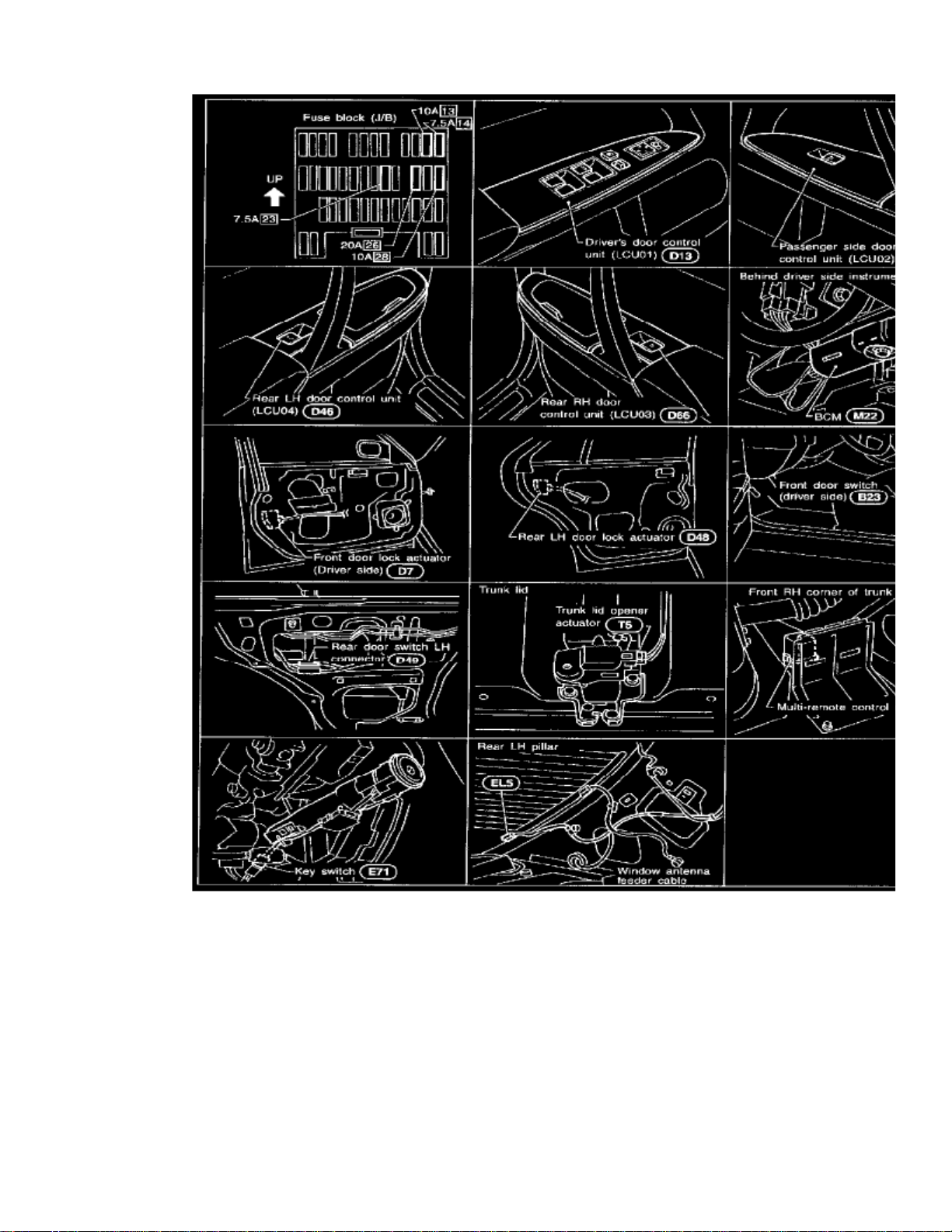
> Relays and Modules > Relays and Modules - Body and Frame > Door Module > Component Information > Locations
Door Module: Locations
Page 25

> Relays and Modules > Relays and Modules - Body and Frame > Door Module > Component Information > Locations > Page 26
Q45 V8-4130cc 4.1L DOHC MFI (VH41) (1998)
Page 26

Page 27

> Relays and Modules > Relays and Modules - Body and Frame > Door Module > Component Information > Locations > Page 27
Q45 V8-4130cc 4.1L DOHC MFI (VH41) (1998)
Page 28
Page 29

> Relays and Modules > Relays and Modules - Body and Frame > Door Module > Component Information > Locations > Page 28
Q45 V8-4130cc 4.1L DOHC MFI (VH41) (1998)
Page 30

Page 31

> Relays and Modules > Relays and Modules - Body and Frame > Door Module > Component Information > Locations > Page 29
Q45 V8-4130cc 4.1L DOHC MFI (VH41) (1998)
Page 32

Component Parts and Harness Connector Location
Page 33

Page 34

> Relays and Modules > Relays and Modules - Body and Frame > Power Seat Control Module > Component Information > Locations > Component Locations
Power Seat Control Module: Component Locations
Passenger Compartment
Page 35

> Relays and Modules > Relays and Modules - Body and Frame > Power Seat Control Module > Component Information > Locations > Component Locations > Page 34
Q45 V8-4130cc 4.1L DOHC MFI (VH41) (1998)
Page 36

Component Parts and Harness Connector Location
Page 37

Page 38

> Relays and Modules > Relays and Modules - Body and Frame > Power Seat Control Module > Component Information > Locations > Component Locations > Page 35
Power Seat Control Module: Connector Locations
Passenger Compartment
Page 39

> Relays and Modules > Relays and Modules - Body and Frame > Power Seat Control Module > Component Information > Locations > Component Locations > Page 36
Q45 V8-4130cc 4.1L DOHC MFI (VH41) (1998)
Page 40

Component Parts and Harness Connector Location
Page 41

Page 42

> Relays and Modules > Relays and Modules - Body and Frame > Sunroof / Moonroof Relay > Component Information > Locations
Sunroof / Moonroof Relay: Locations
Passenger Compartment
Page 43

Page 44

> Relays and Modules > Relays and Modules - Brakes and Traction Control > Brake Fluid Solenoid Valve Relay > Component Information > Locations
Brake Fluid Solenoid Valve Relay: Locations
Component Parts and Harness Connector Location
Page 45

Page 46

> Relays and Modules > Relays and Modules - Brakes and Traction Control > Electronic Brake Control Module > Component Information > Specifications
Electronic Brake Control Module: Specifications
TIGHTENING SPECIFICATIONS
Mounting Nut and Bolt ............................................................................................................................................... 3.9 - 5.9 Nm (34.7 - 52.1 inch lbs.)
Page 47

Page 48

> Relays and Modules > Relays and Modules - Brakes and Traction Control > Electronic Brake Control Module > Component Information > Specifications > Page 47
Electronic Brake Control Module: Locations
Component Parts and Harness Connector Location
Page 49

Page 50

> Relays and Modules > Relays and Modules - Brakes and Traction Control > Electronic Brake Control Module > Component Information > Specifications > Page 48
Electronic Brake Control Module: Service and Repair
CAUTION:
^ When disconnecting or connecting connectors, check terminals to ensure that they are not bent or otherwise damaged.
^ When installing trunk trim clips, be careful not to bend control unit bracket or bump control unit.
Location: Inside instrument panel on passenger's seat side, near front pillar
Page 51

Page 52

> Relays and Modules > Relays and Modules - Brakes and Traction Control > Traction Control Module > Component Information > Locations
Traction Control Module: Locations
Component Parts and Harness Connector Location
Page 53

Page 54

> Relays and Modules> Relays and Modules - Brakes and Traction Control > Traction Control Module > Component Information > Testing and Inspection > Component Tests and General Diagnostics
Traction Control Module: Component Tests and General Diagnostics
Self-Diagnosis For ABS/TCS Control Unit
FUNCTION
-
When a problem occurs in the ABS, the SLIP indicator on the instrument panel comes on. To start the self-diagnostic results mode, ground theself-diagnostic (check) terminal located on "Data Link Connector for CONSULT". The location of the malfunction is indicated by the SLIPindicator flashing.
SELF-DIAGNOSIS PROCEDURE
Page 55

> Relays and Modules> Relays and Modules - Brakes and Traction Control > Traction Control Module > Component Information > Testing and Inspection > Component
Tests and General Diagnostics > Page 54
Q45 V8-4130cc 4.1L DOHC MFI (VH41) (1998)
Page 56

HOW TO READ SELF-DIAGNOSTIC RESULTS (Malfunction codes)
- Determine the code No. by counting the number of times the SLIP indicator flashes on and off.
- When several malfunctions occur at one time, up to three code numbers can be stored; the latest malfunction will be indicated first.
The indication begins with the start code 12. After that a maximum of three code numbers appear in the order of the latest one first. The indicationthen returns to the start code 12 to repeat (the indication will stay on for five minutes at the most).
HOW TO ERASE SELF-DIAGNOSTIC RESULTS (Malfunction codes)
a. Under the self-diagnostic results mode, the malfunction memory erase mode starts when the check terminal is disconnected from the ground.
b. The self-diagnostic results (malfunction codes) can be erased by grounding the check terminal more than three times in succession within 12.5
seconds after the erase mode starts. (Each grounding must be longer than one second.)The SLIP indicator stays on while the self-diagnosis is in the erase mode, and goes out after the erase operation has been completed.
c. The self-diagnosis is also completed at the same time.
After the erase operation is completed, it is necessary to rerun the self-diagnostic mode to verify that malfunction codes no longer appear. Only thestart code (12) should be indicated when erase operation is completed and system is functioning normally.
Page 57

> Relays and Modules> Relays and Modules - Brakes and Traction Control > Traction Control Module > Component Information > Testing and Inspection > Component
Tests and General Diagnostics > Page 55
Q45 V8-4130cc 4.1L DOHC MFI (VH41) (1998)
The TCS OFF indicator and ABS warning lamp remain lighted.NOTE:
MALFUNCTION CODE/SYMPTOM CHART
Page 58

Page 59

> Relays and Modules> Relays and Modules - Brakes and Traction Control > Traction Control Module > Component Information > Testing and Inspection > Component
Tests and General Diagnostics > Page 56
Q45 V8-4130cc 4.1L DOHC MFI (VH41) (1998)
Self-Diagnosis For TAC Module
SELF-DIAGNOSIS PROCEDURE
Page 60

HOW TO READ SELF-DIAGNOSTIC RESULTS (Malfunction codes)
-
(TAC)
Count the number of Throttle Actuator Control module LED flashes (ten digits and unit digits). If multiple troubles occur, theircorresponding trouble code numbers will be stored in the memory. For indication pattern, start code number 12 will be indicated first. Followingstart code number 12, trouble code numbers will be indicated in numerical order, one at a time, and will be repeated.
- If there is no trouble, only trouble code 55 will be repeatedly indicated.
HOW TO ERASE SELF-DIAGNOSTIC RESULTS (Malfunction codes)
With accelerator pedal fully depressed (full-open throttle), turn neutral position switch "OFF", and place shift lever in any position other than "P"or "N".
After turning ignition switch "ON" (engine off), turn neutral position switch "ON", and place shift lever in "P" or "N". Release accelerator pedal(full-closed throttle).
-
Page 61

> Relays and Modules> Relays and Modules - Brakes and Traction Control > Traction Control Module > Component Information > Testing and Inspection > Component
Tests and General Diagnostics > Page 57
Q45 V8-4130cc 4.1L DOHC MFI (VH41) (1998)
Items indicated in the following table can be erased as per conditions without using erasure procedures outlined above. These items are erasedunder conditions outlined in the table.
Page 62

After the erase operation is completed, it is necessary to rerun the self-diagnostic mode to verify that malfunction codes no longer appear. Only theCode No. 55 should be indicated when erase operation is completed and system is functioning normally.
(TCS)
If the system becomes inoperative, the Traction Control System function will be suspended. The fail-safe system will then activate, illuminatingthe SLIP indicator and TCS OFF indicator. The motor throttle valve will act as one similar to a vehicle which is not equipped with a TCS.
CAUTION:
- If the motor throttle control system becomes inoperative, only the TCS function will be suspended. The ABS function will activate properly.
-
(TCM)
If the Transmission Control Module fail-safe system activates, the self-diagnostic procedure must be performed first on the ABS/TCScontrol system.
TCM FAIL SAFE
Page 63

> Relays and Modules> Relays and Modules - Brakes and Traction Control > Traction Control Module > Component Information > Testing and Inspection > Component
Tests and General Diagnostics > Page 58
Q45 V8-4130cc 4.1L DOHC MFI (VH41) (1998)
Page 64

Page 65

Page 66

> Relays and Modules > Relays and Modules - Brakes and Traction Control > Traction Control Module > Component Information > Testing and Inspection > Component Tests and General Diagnostics > Page 59
Traction Control Module: Scan Tool Testing and Procedures
Active Test Procedure
Page 67

> Relays and Modules> Relays and Modules - Brakes and Traction Control > Traction Control Module > Component Information > Testing and Inspection > Component
Tests and General Diagnostics > Page 60
Q45 V8-4130cc 4.1L DOHC MFI (VH41) (1998)
Active Test Procedure
Page 68

Active Test Mode
Page 69

> Relays and Modules> Relays and Modules - Brakes and Traction Control > Traction Control Module > Component Information > Testing and Inspection > Component
Tests and General Diagnostics > Page 61
Q45 V8-4130cc 4.1L DOHC MFI (VH41) (1998)
Data Monitor Procedure
Page 70

Page 71

> Relays and Modules> Relays and Modules - Brakes and Traction Control > Traction Control Module > Component Information > Testing and Inspection > Component
Tests and General Diagnostics > Page 62
Q45 V8-4130cc 4.1L DOHC MFI (VH41) (1998)
Data Monitor Procedure
Page 72

Page 73

> Relays and Modules> Relays and Modules - Brakes and Traction Control > Traction Control Module > Component Information > Testing and Inspection > Component
Tests and General Diagnostics > Page 63
Q45 V8-4130cc 4.1L DOHC MFI (VH41) (1998)
Data Monitor Mode
Self Diagnostic Procedure
Page 74

Page 75

> Relays and Modules> Relays and Modules - Brakes and Traction Control > Traction Control Module > Component Information > Testing and Inspection > Component
Tests and General Diagnostics > Page 64
Q45 V8-4130cc 4.1L DOHC MFI (VH41) (1998)
Self-Diagnosis Procedure
Page 76

Page 77

> Relays and Modules> Relays and Modules - Brakes and Traction Control > Traction Control Module > Component Information > Testing and Inspection > Component
Tests and General Diagnostics > Page 65
Q45 V8-4130cc 4.1L DOHC MFI (VH41) (1998)
Self Diagnostic Results Mode (Part 1 Of 2)
Page 78

Self Diagnostic Results Mode (Part 2 Of 2)
Active Test Procedure
Page 79

> Relays and Modules> Relays and Modules - Brakes and Traction Control > Traction Control Module > Component Information > Testing and Inspection > Component
Tests and General Diagnostics > Page 66
Q45 V8-4130cc 4.1L DOHC MFI (VH41) (1998)
Page 80

Page 81

> Relays and Modules> Relays and Modules - Brakes and Traction Control > Traction Control Module > Component Information > Testing and Inspection > Component
Tests and General Diagnostics > Page 67
Q45 V8-4130cc 4.1L DOHC MFI (VH41) (1998)
Active Test Procedure (Part 1 Of 2)
Page 82

Active Test Procedure (Part 2 Of 2)
Active Test Mode
Page 83

> Relays and Modules> Relays and Modules - Brakes and Traction Control > Traction Control Module > Component Information > Testing and Inspection > Component
Tests and General Diagnostics > Page 68
Q45 V8-4130cc 4.1L DOHC MFI (VH41) (1998)
Data Monitor Procedure
Page 84

Page 85

> Relays and Modules> Relays and Modules - Brakes and Traction Control > Traction Control Module > Component Information > Testing and Inspection > Component
Tests and General Diagnostics > Page 69
Q45 V8-4130cc 4.1L DOHC MFI (VH41) (1998)
Data Monitor Procedure
Page 86

Data Monitor Mode
Self Diagnostic Procedure
Page 87

> Relays and Modules> Relays and Modules - Brakes and Traction Control > Traction Control Module > Component Information > Testing and Inspection > Component
Tests and General Diagnostics > Page 70
Q45 V8-4130cc 4.1L DOHC MFI (VH41) (1998)
Page 88

Page 89

> Relays and Modules> Relays and Modules - Brakes and Traction Control > Traction Control Module > Component Information > Testing and Inspection > Component
Tests and General Diagnostics > Page 71
Q45 V8-4130cc 4.1L DOHC MFI (VH41) (1998)
Self Diagnostic Procedure
Page 90

Self Diagnostic Results Mode
Page 91

Page 92

> Relays and Modules > Relays and Modules - Brakes and Traction Control > Traction Control Module > Component Information > Testing and Inspection > Component Tests and General Diagnostics > Page 72
Traction Control Module: Pinout Values and Diagnostic Parameters
INSPECTION OF ABS/TCS CONTROL UNIT
-
Check that voltage between ABS/Traction Control System control unit terminals is within the following reference value.(TCS)
Page 93

> Relays and Modules> Relays and Modules - Brakes and Traction Control > Traction Control Module > Component Information > Testing and Inspection > Component
Tests and General Diagnostics > Page 73
Q45 V8-4130cc 4.1L DOHC MFI (VH41) (1998)
Page 94

Page 95

Page 96

> Relays and Modules > Relays and Modules - Brakes and Traction Control > Traction Control Module > Component Information > Service and Repair > Throttle Actuator Control (TAC) Control Unit
Traction Control Module: Service and RepairThrottle Actuator Control (TAC) Control Unit
CAUTION:
- When disconnecting or connecting connectors, check terminals to ensure that they are not bent or otherwise damaged.
When installing trunk trim clips, be careful not to bend control unit bracket or bump control unit.Location: Passenger side, behind dash side lower finisher
Page 97

Page 98

> Relays and Modules > Relays and Modules - Brakes and Traction Control > Traction Control Module > Component Information > Service and Repair > Throttle Actuator Control (TAC) Control Unit > Page 76
Traction Control Module: Service and RepairABS-TCS Module
CAUTION:
^ When disconnecting or connecting connectors, check terminals to ensure that they are not bent or otherwise damaged.
^ When installing trunk trim clips, be careful not to bend control unit bracket or bump control unit.
Location: Inside instrument panel on passenger's seat side, near front pillar
Page 99

Page 100

> Relays and Modules > Relays and Modules - Brakes and Traction Control > Traction Control Relay > Component Information > Locations
Traction Control Relay: Locations
Component Parts and Harness Connector Location
 Loading...