

Page 1

Foreword
Your INFINITI represents a new way of
thinking about vehicle design. It integrates advanced engineering and superior craftsmanship with a simple, refined
aesthetic sensitivity associated with traditional Japanese culture.
The result is a different notion of luxury
and beauty. The car itself is important,
but so is the sense of harmony that the
vehicle evokes in its driver, and the
sense of satisfaction you feel with the
INFINITI — from the way it looks and
drives to the high level of dealer service.
To ensure that you enjoy your INFINITI to
the fullest, we encourage you to read this
Owner’s Manual immediately. It explains
all of the features, controls and performance characteristics of your INFINITI; it
also provides important instructions and
safety information.
A separate Warranty Information Booklet is included in your Owner’s literature portfolio. The
INFINITI Service and Maintenance Guide explains details about maintaining and servicing
your vehicle. Alwayscarry it withyou when you
take your vehicle to an INFINITI dealer. The
Warranty Information Booklet contents provide complete information about all warranties
covering this vehicle,the requirements tokeep
the warranties in effect as well as the INFINITI
Roadside Assistance program.
Additionally, a separate Customer Care
and Lemon Law Information Booklet will
explain how to resolve any concerns you
may have with your vehicle, as well as
clarify your rights under your state’s
lemon law.
INFINITI is dedicated to providing a satisfying ownership experience for as long as
you own your car. Should you have any
questions regarding your INFINITI or your
INFINITI dealer, please contact our Consumer Affairs department at:
In U.S. 1-800-662-6200.
In Canada 1-800-361-4792.
READ FIRST — THEN DRIVE SAFELY
Before driving your vehicle, read your
Owner’s Manual carefully. This will ensure familiarity with controls and maintenance requirements, assisting you in the
safe operation of your vehicle.
WARNING
IMPORTANT SAFETY INFORMATION
REMINDERS FOR SAFETY!
Follow these important driving rules to help
ensure a safe andcomfortable trip for you and
your passengers!
O NEVER drive under the influence of al-
cohol or drugs.
O ALWAYS observe posted speed limits and
never drive too fast for conditions.
O ALWAYS give your full attention to driving
and avoid using vehicle features ortaking
other actions that could distract you.
O ALWAYS use your seat belts and appro-
priate child restraint systems. Pre-teen
children should be seated in the rear
seat.
O ALWAYS provide information about the
proper use of vehiclesafety features to all
occupants of the vehicle.
O ALWAYS review this Owner’s Manual for
important safety information.
MODIFICATION OF YOUR VEHICLE
This vehicle should notbe modified. Modification could affect its performance,
safety or durability, and may even violate
governmental regulations. In addition,
damage or performance problems resulting from modification will not be covered under the INFINITI warranties.
WHEN READING THE MANUAL
This manual includes information for all
options available on this model. Therefore, you may find some information that
does not apply to your vehicle.
Page 2
All information, specifications and illustrations in this manual are those in effect
at the time of printing. INFINITI reserves
the right to change specifications or design at any time without notice.
IMPORTANT INFORMATION ABOUT
THIS MANUAL
You will see various symbols in this
manual. They are used in the following
ways:
WARNING
This is used to indicate the presence of a
hazard that could cause death or serious
personal injury. To avoid or reduce the risk,
the procedures must be followed precisely.
CAUTION
This is used to indicate the presence of a
hazard that could cause minor or moderate
personal injury ordamage to your vehicle.To
avoid or reduce the risk, the procedures
must be followed carefully.
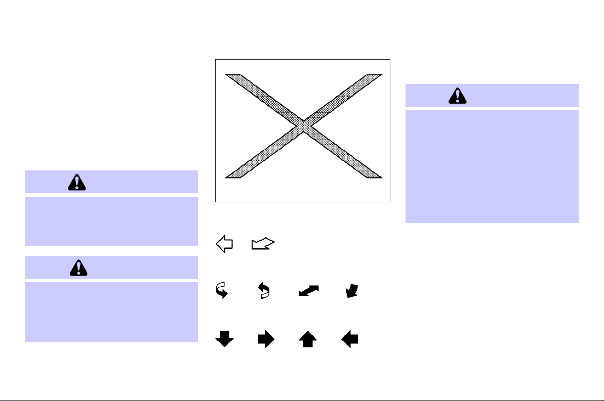
SIC0697
If you see the symbol above, it means
“Do not do this” or “Do not let this
happen”.
If you see a symbol similar to those
above in an illustration, it means the
arrow points to the front of the vehicle.
Arrows in an illustration that are similar
to those above indicate movement or action.
Arrows in an illustration that are similar
to those above call attention to an item
in the illustration.
CALIFORNIA PROPOSITION 65
WARNING
WARNING
Engine Exhaust, some of its constituents,
and certain vehicle components contain or
emit chemicals known to theState of California to causecancer and birthdefects or other
reproductive harm. In addition, certain fluids
contained in vehicles and certainproducts of
component wear contain or emit chemicals
known to the State of California to cause
cancer and birth defects or other reproductive harm.
CALIFORNIA PERCHLORATE
ADVISORY
Some vehicle parts, such as lithium batteries, may contain perchlorate material. The
following advisory is provided: “Perchlorate
Material — special handling may apply.
See www.dtsc.ca.gov/hazardouswaste/
perchlorate.”
Page 3

BLUETOOTH is a trademark
owned by Bluetooth SIG,
Inc., U.S.A. and licenced to
Xanavi Informatics Corporation.
© 2006 NISSAN MOTOR CO., LTD.
All rights reserved. No part of this Owner’s
Manual may be reproduced or stored in a retrieval system, or transmitted in any form, or by
any means, electronic, mechanical, photocopying, recording or otherwise, without the prior
written permission of Nissan Motor Co., Ltd.
Page 4

Table of
Illustrated table of contents
0
Contents
Safety — Seats, seat belts and supplemental restraint system
Instruments and controls
Pre-driving checks and adjustments
Monitor, climate, audio, phone and voice recognition systems
Starting and driving
In case of emergency
Appearance and care
Maintenance and do-it-yourself
Technical and consumer information
Index
1
2
3
4
5
6
7
8
9
10
Page 5

0 Illustrated table of contents
Seats, seat belts and supplemental restraint
system (SRS) .................................................... 0-2
Exterior front .................................................... 0-3
Exterior rear ..................................................... 0-4
Passenger compartment ................................... 0-5
Cockpit............................................................. 0-7
Instrument panel.............................................. 0-8
Meters and gauges........................................... 0-9
Engine compartment ....................................... 0-10
VK45DE engine .......................................... 0-10
VQ35DE engine........................................... 0-11
Page 6
SEATS, SEAT BELTS AND SUPPLEMENTAL
RESTRAINT SYSTEM (SRS)
7. Rear armrest (P.1-7)
8. LATCH (Lower Anchor and Tethers for
CHildren) System (P.1-18)
9. Supplemental side-impact air bags
(P.1-36)
10. Front armrest (P.1-6)
11. Supplemental front-impact air bags
(P.1-36)
SSI0223
1. Top tether strap anchors (P.1-20)
2. Head restraints (P.1-5)
3. Seat belts (P.1-8)
0-2 Illustrated table of contents
4. Supplemental curtain side-impact air
bags (P.1-36)
5. Seats (P.1-2)
6. Front passenger air bag status light
(P.1-44)
Page 7
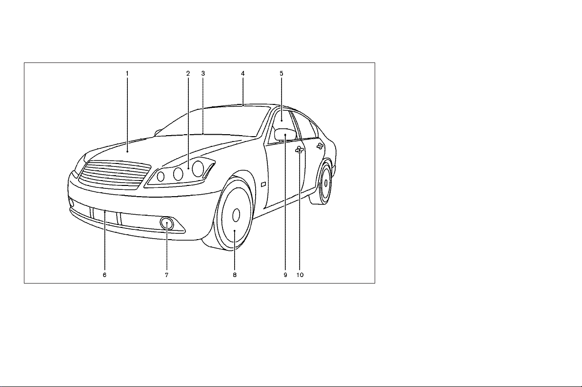
EXTERIOR FRONT
6. Recovery hook (P.6-14)
7. Fog lights (P.2-31)
8. Tires
— Wheel and tires (P.8-34, P.9-8)
— Flat tire (P.6-2)
9. Outside mirrors (P.3-24)
10. Doors
— Keys (P.3-2)
— Door locks (P.3-5)
— Intelligent Key system (P.3-8)
— Remote keyless entry system
(P.3-14)
SSI0088
1. Hood (P.3-17)
2. Headlight and turn signal
— Operation (P.2-26)
— Bulb replacement (P.8-30)
— Adaptive Front lighting System (AFS)
(if so equipped) (P.2-29)
3. Windshield wiper and washer
— Operation (P.2-25)
— Blade replacement (P.8-24)
4. Sunroof (P.2-46)
5. Power windows (P.2-44)
Illustrated table of contents 0-3
Page 8
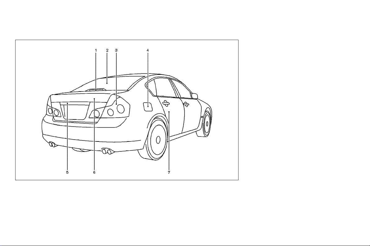
EXTERIOR REAR
6. Trunk
— Intelligent Key system (P.3-8)
— Remote keyless entry system
(P.3-14)
— Trunk lid (P.3-18)
7. Child safety locks (P.3-7)
SSI0233
1. High-mounted stop light (Bulb replacement) (P.8-30)
2. Rear window defroster switch (P.2-26)
3. Rear combination light (Bulb replace-
ment) (P.8-30)
0-4 Illustrated table of contents
4. Fuel-filler door
— Operation (P.3-20)
— Fuel recommendation (P.9-3)
5. Rear view camera (P.4-19)
Page 9
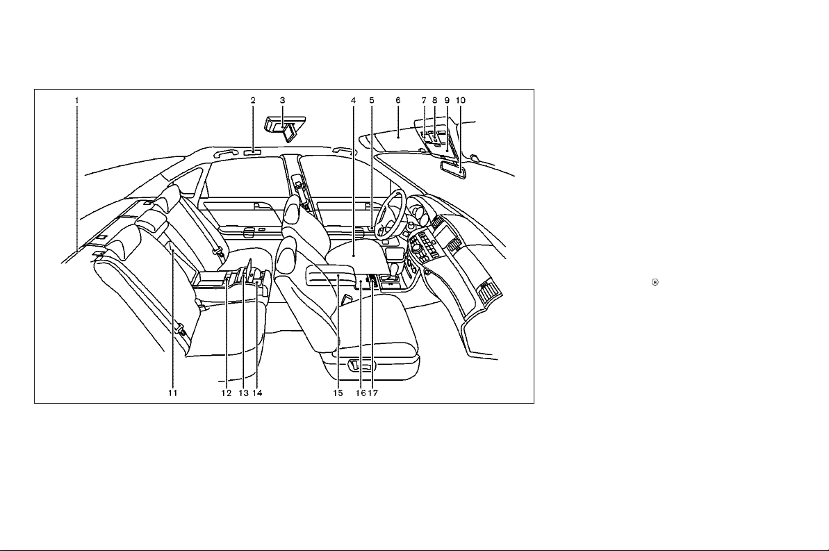
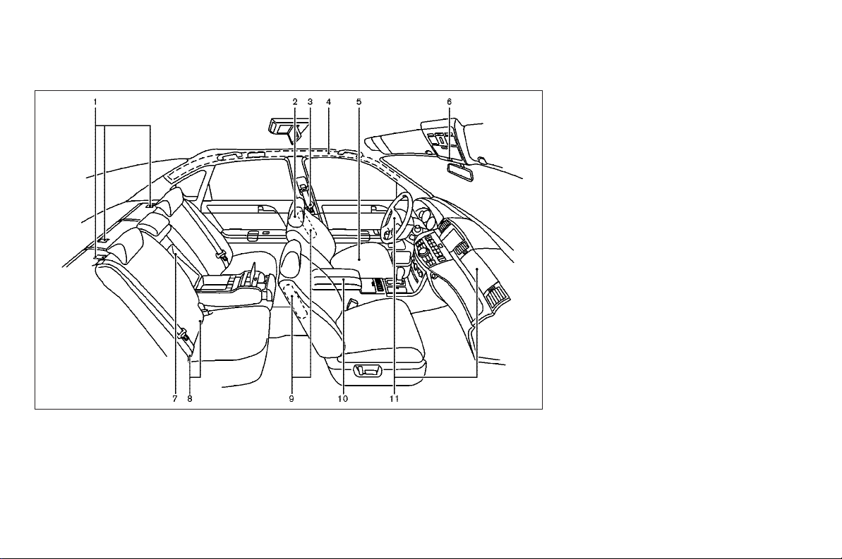
PASSENGER COMPARTMENT
1. Rear sunshade (if so equipped)
(P.2-48)
2. Rear personal light (P.2-50)/Coat
hooks (P.2-43)
SSI0226
3. Mobile entertainment system (MES) (if
so equipped) (P.4-46)
— Flip-down screen (P.4-48)
— Digital Versatile Disc (DVD) drive
(P.4-47)
— Headphones (P.4-49)
— DVD remote controller (P.4-50,
P.4-56)
4. Seats (P.1-2)
5. Power windows (P.2-44)
6. Sun visors (P.3-22)
7. Map light (P.2-49)
8. Sunroof (P.2-46)
9. Sunglasses holder (P.2-41)
10. Inside rearview mirror
— Anti-glare adjustment (P.3-23)
— HomeLink
— Compass (P.2-8)
11. Trunk pass-through (P.1-7)/Rear arm-
rest (P.1-7)
12. Rear seat controls (if so equipped)
— Rear power seat adjust switch
(P.1-4)
— Heated seat ON/OFF switch
(P.2-33)
— Automatic return ON/CANCEL
switch (P.1-4)
— Rear sunshade control switch
(P.2-49)
(P.2-52)
Illustrated table of contents 0-5
Page 10

13. Rear passenger control switches (if so
equipped)
— For air conditioner (P.4-27)
— For audio (P.4-45)
14. Rear cup holders (P.2-39)
15. Front console (P.2-42)/Front armrest
(P.1-6)
16. Front cup holders (P.2-39)
17. Front seat controls (if so equipped)
— Climate controlled seat adjusting
knob (P.2-34)
— Rear sunshade control switch
(P.2-49)
— Rear passenger controls
ON/CANCEL switch (P.2-48)
— SNOW MODE ON/OFF switch
(P.2-36)
0-6 Illustrated table of contents
Page 11
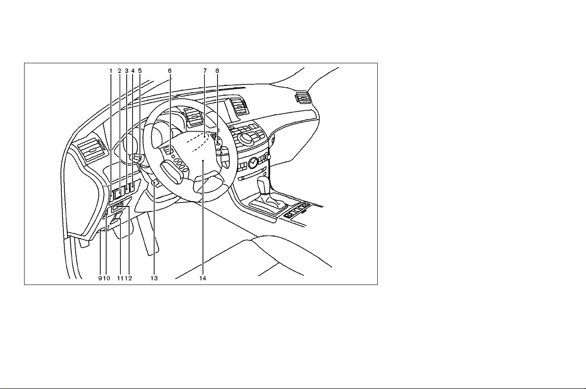
COCKPIT
1. Instrument brightness control switch
(P.2-30)
2. Outside mirror remote control (P.3-24)
3. Adaptive Front lighting System (AFS)
switch (if so equipped) (P.2-29)
SSI0090
4. Vehicle Dynamic Control (VDC) OFF
switch (P.2-36)
5. Headlight, fog light and turn signal
switch (P.2-26)
6. Steering-wheel-mounted controls (Left
side)
— ENTER switch (P.4-5, P.4-43)
— BACK switch (P.4-43)
— TALK switch (P.4-68)/Phone switch
(P.4-61)
— Volume control switches (P.4-44)
— Source select switch (P.4-43)
7. Windshield wiper and washer switch
(P.2-25)
8. Steering-wheel-mounted controls
(Right side)
— Cruise control switches (P.5-19)
— Intelligent Cruise Control (ICC)
switches (if so equipped) (P.5-21)
9. Hood release handle (P.3-17)
10. Trunk lid release switch (P.3-18)
11. Lane Departure Warning (LDW) switch
(if so equipped) (P.2-35, P.5-15)
12. Intelligent Key port (P.5-8)
13. Tilting/telescopic steering wheel
switch (P.3-22)
14. Steering wheel
— Horn (P.2-32)
— Driver supplemental air bag
(P.1-36)
Illustrated table of contents 0-7
Page 12
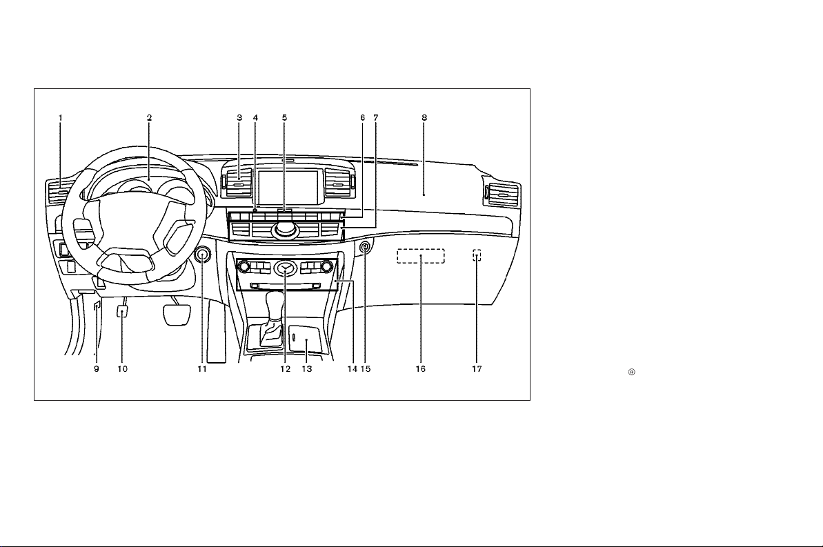
INSTRUMENT PANEL
1. Side ventilator (P.4-23)
2. Meters and gauges (P.2-4)
3. Center ventilator (P.4-23)
4. Security indicator light (P.2-24)
0-8 Illustrated table of contents
SSI0091
5. Hazard warning flasher switch
(P.2-32)
6. Automatic climate control system
(P.4-24)
7. Center multi-function control panel
— Navigation system (if so equipped)
— Vehicle information and setting but-
tons (P.4-6)
— Phone system (P.4-60)
— Audio system (P.4-29)
8. Front passenger supplemental air bag
(P.1-36)
9. Fuse box cover (P.8-26)
10. Parking brake pedal
— Parking (P.5-45)
— Maintenance (P.8-25)
11. Push-button ignition switch (P.5-8)
12. Clock (P.2-37)
13. Cigarette lighter and ashtrays
(P.2-38)
14. Audio system (P.4-29)
15. Glove box lid release button (P.2-41)
16. Bluetooth
module (P.4-60)/DVD drive for navigation system (if so equipped)
17. Trunk release power cancel switch
(P.3-19)
in-vehicle phone
Page 13
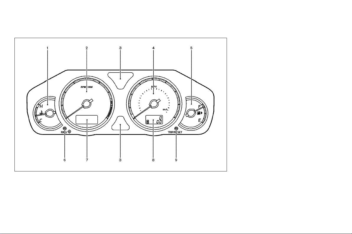
METERS AND GAUGES
9. TRIP/RESET knob for twin trip
odometer (P.2-5)
SSI0092
1. Engine coolant temperature gauge
(P.2-6)
2. Tachometer (P.2-5)
3. Warning/indicator lights (P.2-11)
4. Speedometer (P.2-5)
5. Fuel gauge (P.2-6)
6. Meter illumination control knob (P.2-7)
7. Dot matrix liquid crystal display
(P.2-20)
8. Odometer/twin trip odometer (P.2-5)
Illustrated table of contents 0-9
Page 14
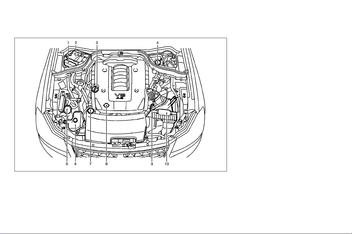
ENGINE COMPARTMENT
8. Radiator filler cap (P.8-10)
9. Engine oil dipstick (P.8-13)
10. Air cleaner (P.8-22)
* Shown with the engine compartment
access panels removed. For removal
and replacement instructions, see “Engine compartment check locations” in
the “8. Maintenance and do-it-yourself”
section.
SSI0097
VK45DE ENGINE*
1. Fuse/fusible link holder (P.8-26)
2. Battery (P.8-18)
3. Engine oil filler cap (P.8-13)
0-10 Illustrated table of contents
4. Brake fluid reservoir (P.8-17)
5. Window washer fluid reservoir
(P.8-18)
6. Coolant reservoir (P.8-10)
7. Power steering fluid reservoir (P.8-17)
Page 15
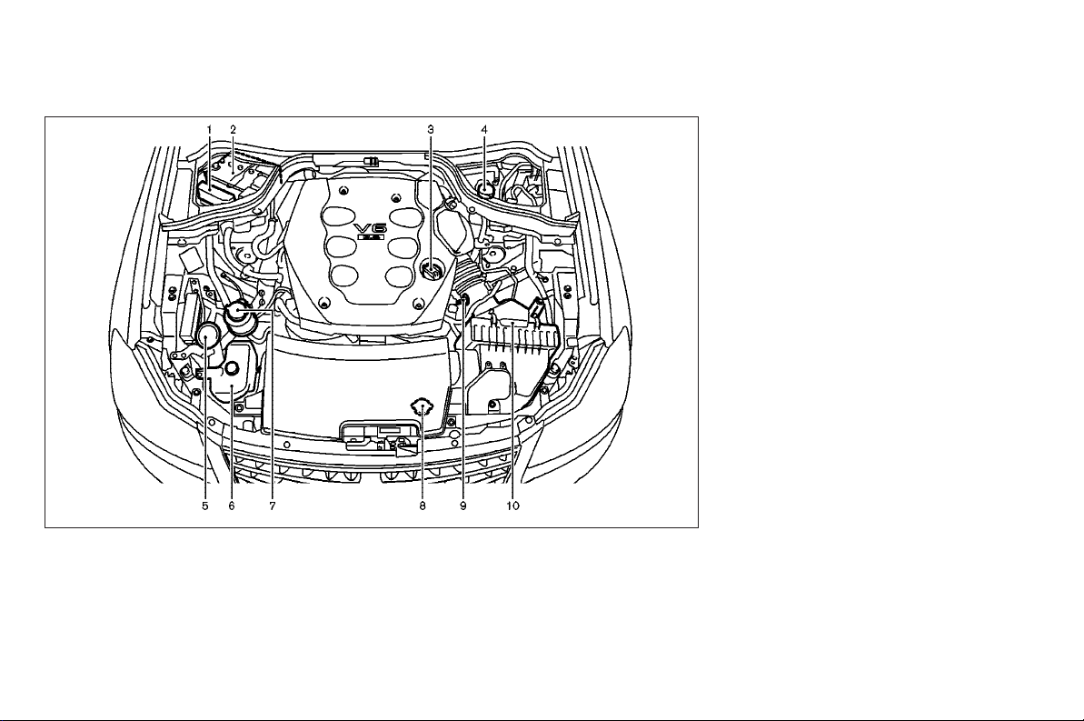
SSI0098
8. Radiator filler cap (P.8-10)
9. Engine oil dipstick (P.8-13)
10. Air cleaner (P.8-22)
* Shown with the engine compartment
access panels removed. For removal
and replacement instructions, see “Engine compartment check locations” in
the “8. Maintenance and do-it-yourself”
section.
VQ35DE ENGINE*
1. Fuse/fusible link holder (P.8-26)
2. Battery (P.8-18)
3. Engine oil filler cap (P.8-13)
4. Brake fluid reservoir (P.8-17)
5. Window washer fluid reservoir
(P.8-18)
6. Coolant reservoir (P.8-10)
7. Power steering fluid reservoir (P.8-17)
Illustrated table of contents 0-11
Page 16

MEMO
0-12 Illustrated table of contents
Page 17

1
Safety — Seats, seat belts and supplemental
restraint system
Seats ................................................................ 1-2
Front seats................................................... 1-2
Rear seats ................................................... 1-4
Head restraint.............................................. 1-5
Armrest........................................................ 1-6
Seat belts ......................................................... 1-8
Precautions on seat belt usage.................... 1-8
Child safety................................................ 1-10
Pregnant women......................................... 1-11
Injured persons........................................... 1-11
Pre-crash seat belts (front seats) (if so
equipped)................................................... 1-12
Three-point type seat belt .......................... 1-12
Seat belt extenders .................................... 1-15
Seat belt maintenance ............................... 1-16
Child restraints................................................ 1-16
Precaution on child restraints..................... 1-16
Lower anchors and tethers for children
system (LATCH) .......................................... 1-18
Top tether strap child restraint .................. 1-20
Child restraint installation using LATCH...... 1-21
Child restraint installation using the seat
belts .......................................................... 1-25
Booster seats.................................................. 1-32
Precautions on booster seats .................... 1-32
Booster seat installation ............................ 1-34
Supplemental restraint system........................ 1-36
Precautions on supplemental restraint
system....................................................... 1-36
INFINITI advanced air bag system (front
seats) ........................................................ 1-42
Supplemental side air bag and curtain
side-impact air bag system ........................ 1-47
Pre-tensioner seat belt system (front
seats) ........................................................ 1-49
Supplemental air bag warning labels ......... 1-50
Supplemental air bag warning light ........... 1-50
Repair and replacement procedure ............. 1-51
Page 18
SEATS
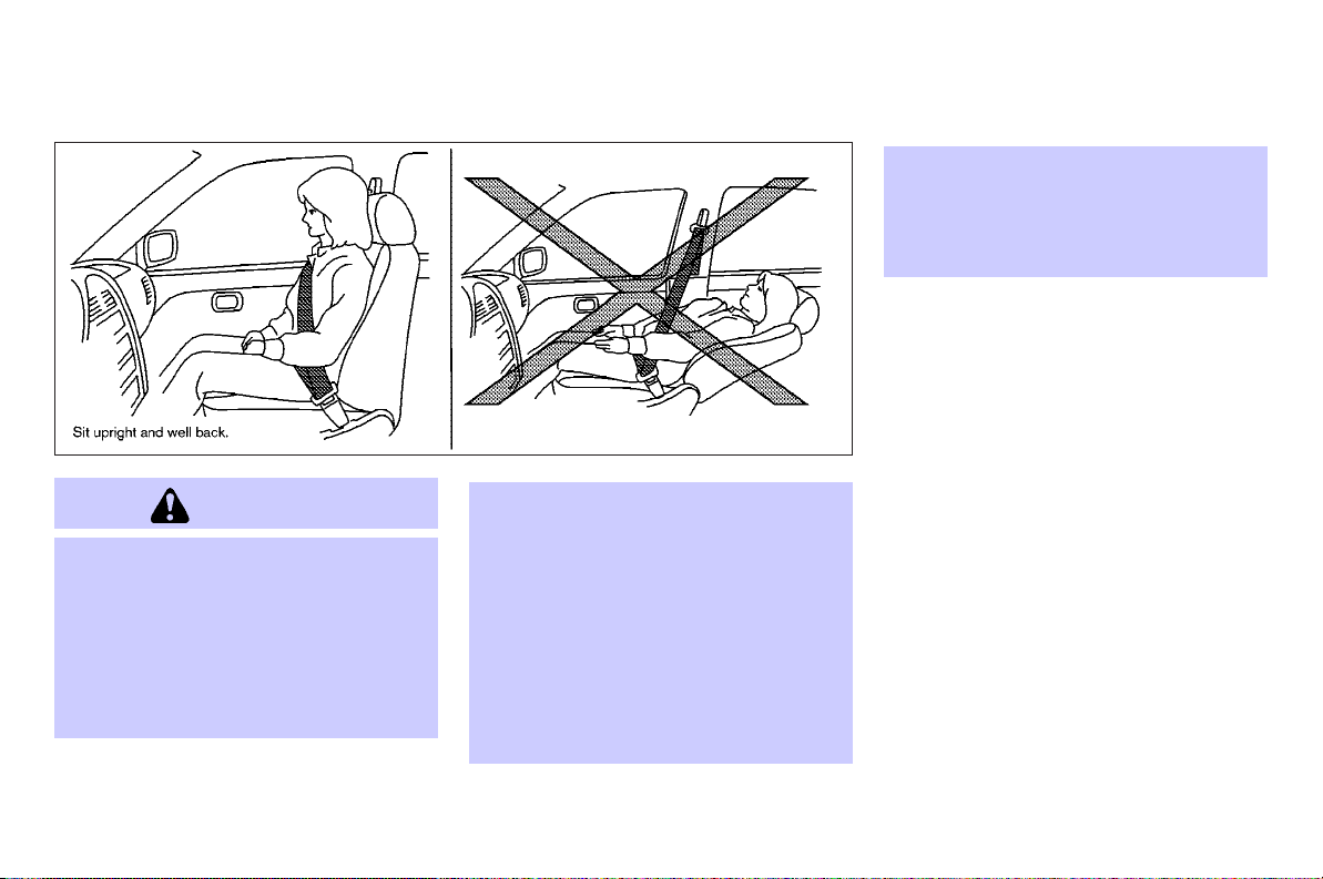
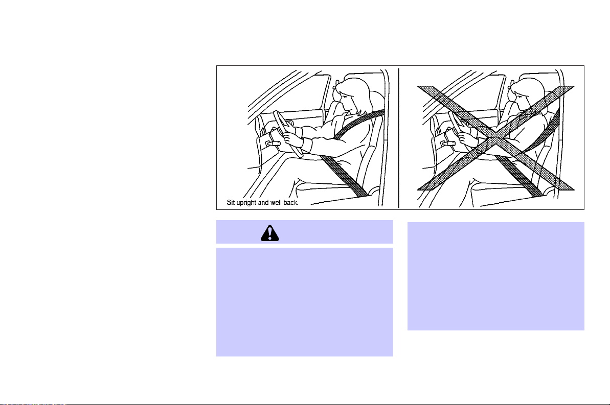
WARNING
O Do not ride in a moving vehicle when the
seatback is reclined. This can be dangerous. The shoulder belt will not be
against your body. In an accident, you
could be thrown into it and receive neck
or other serious injuries. You could also
slide under the lap belt and receive serious internal injuries.
SSS0133
For the most effective protection when
O
the vehicle is in motion, the seat should
be upright. Always sit well back in the
seat with both feet onthe floor and adjust
the seat belt properly. See “Precautions
on seat belt usage” later in this section.
O Do not adjust the driver’s seat while
driving so full attention may be given to
vehicle operation. The seat may move
suddenly and could cause loss of control
of the vehicle.
O Do not leave children unattended inside
the vehicle. They could unknowingly activate switches or controls. Unattended
children could become involved in serious accidents.
FRONT SEATS
Front power seat adjustment
Operating tips:
O The seat motor has an auto-reset over-
load protection circuit. If the motor
stops during operation, wait 30 seconds, then reactivate the switch.
O Do not operate the power seat for a
long period of time when the engine is
off. This will discharge the battery.
See “Automatic drive positioner” in the
“3. Pre-driving checks and adjustments”
section for automatic drive positioner operation.
1-2 Safety — Seats, seat belts and supplemental restraint system
Page 19
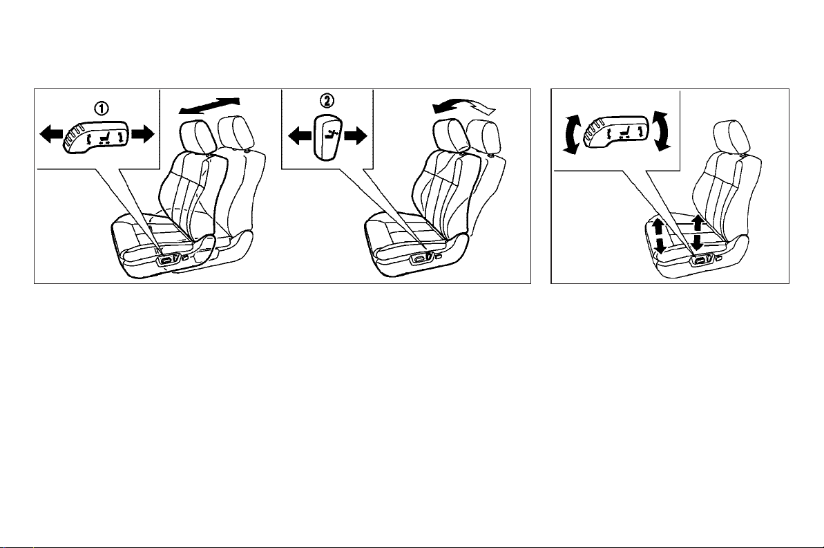
SSS0474 SSS0475
Forward and backward:
forward.
1
forward or back-
q
2
q
backward
Moving the switch
ward will slide the seat forward or backward to the desired position.
Reclining:
Move the recline switch
until the desired angle is obtained. To
bring the seatback forward again, move
the switch
The reclining feature allows adjustment of
the seatback for occupants of different
sizes for added comfort and to help obtain proper seat belt fit. (See “Precautions
q
2
on seat belt usage” later in this section.)
The seatback may also be reclined to
allow occupants to rest when the vehicle
is parked.
Safety — Seats, seat belts and supplemental restraint system 1-3
Seat lifter:
Push the front or rear end of the switch
up or down to adjust the height and angle
of the seat.
Page 20
SSS0476 SSS0631 SSS0478
Lumbar support:
The lumbar support feature provides
lower back support. Push the front
2
back
seat lumbar area.
end of the switch to adjust the
q
q
1
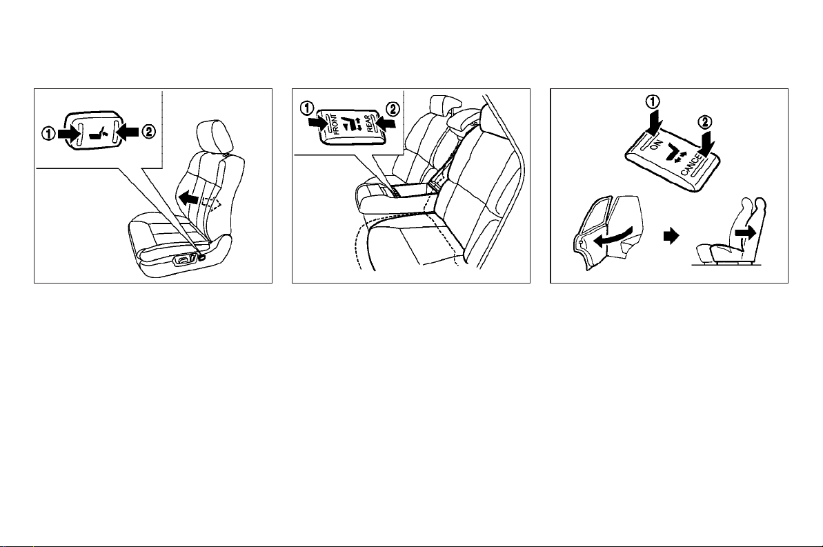
REAR SEATS
Rear power seat adjustment (if so
or
equipped)
Forward and backward:
Push the front
switch to move the rear outboard seats
forward or backward. The seats move continuously while the switch is being
pushed.
1-4 Safety — Seats, seat belts and supplemental restraint system
q
1
or back
2
end of the
q
Entry/exit assist (automatic return):
Pushing the ON side
cated on the rear center armrest, the automatic return function will activate.
When a rear door is opened, the rear seat
of the corresponding side automatically
slides all the way back, facilitating ease
of entry and exit.
Pushing the CANCEL side
will deactivate the automatic return function.
1
of the switch lo-
q
2
of the switch
q
Page 21
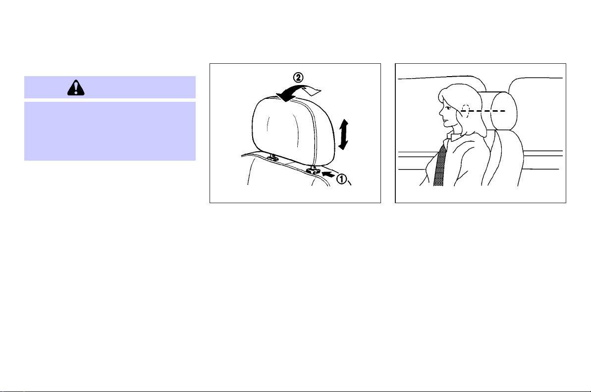
HEAD RESTRAINT
WARNING
Head restraints should be adjusted properly
as they may provide significant protection
against injury in an accident. Do not remove
them. Check the adjustment after someone
else uses the seat.
SSS0228A SSS0287
Adjustment
To raise the head restraint, pull it up.
To lower, push the lock knob
the head restraint down.
To adjust the head restraint angle
push it in the direction required (front
seat head restraints).
1
and push
q
2
q
Safety — Seats, seat belts and supplemental restraint system 1-5
Adjust the head restraint so the center is
level with the center of your ears.
,
Page 22
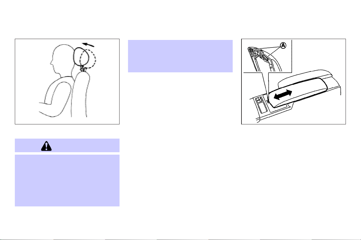
SPA1278 SIC2783
Active head restraint (front seats)
WARNING
O Always adjust the head restraints prop-
erly as specified in the previous section.
Failure to do so can reduce the effectiveness of the active head restraint.
O Active head restraints are designed to
supplement other safety systems. Always wear seat belts. No system can
prevent all injuries in any accident.
O Do not attach anything to the head re-
straint stalks. Doing so could impair active head restraint function.
The active head restraint moves forward
utilizing the force that the seatback receives from the occupant in a rear-end
collision. The movement of the head restraint helps support the occupant’s head
by reducing its backward movement and
helping absorb some of the forces that
may lead to whiplash type injuries.
Active head restraints are effective for collisions at low to medium speeds in which
it is said that whiplash injury occurs
most.
Active head restraints operate only in certain rear-end collisions. After the collision, the head restraints return to their
original positions.
Properly adjust the active head restraints
as described in the previous section.
ARMREST
Front armrest
Pull the lever
or passenger’s armrest forward and backward.
Slide the armrest to the original position
when using the front cup holders.
A
q
up and slide the driver’s
1-6 Safety — Seats, seat belts and supplemental restraint system
Page 23
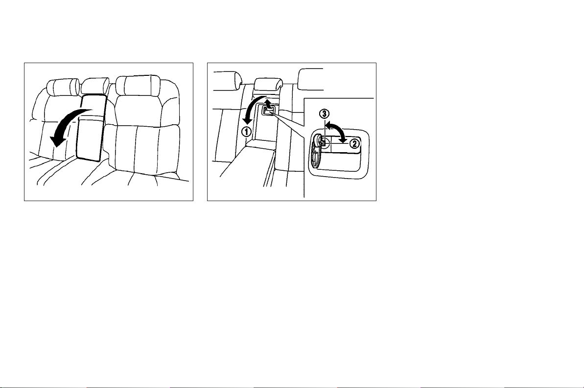
SSS0520 SSS0479
the “3. Pre-driving checks and adjustments” section.
Make sure that the mechanical key is removed from the trunk pass-through lid
key cylinder before opening or closing the
lid. Otherwise the lid and the rear armrest
may be damaged.
Rear armrest
Pull the armrest forward until it is horizontal.
Trunk pass-through
The rear center seatback can be folded to
allow trunk access from inside of the vehicle.
To access the trunk, pull down the rear
center armrest and pull out the trunk
pass-through lid
To lock the lid, use the mechanical key
and turn it to the LOCK position
unlock, turn the mechanical key to the
UNLOCK position
key usage, see “Keys (Intelligent Key)” in
1
.
q
3
. For the mechanical
q
Safety — Seats, seat belts and supplemental restraint system 1-7
q
2
.To
Page 24
SEAT BELTS
PRECAUTIONS ON SEAT BELT
USAGE
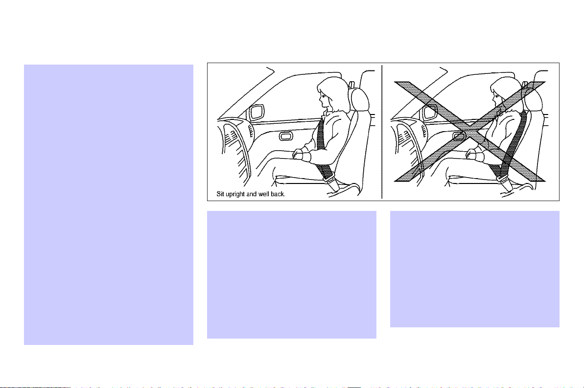
If you are wearing your seat belt properly
adjusted, and you are sitting upright and
well back in your seat with both feet on
the floor, your chances of being injured or
killed in an accident and/or the severity
of injury may be greatly reduced. INFINITI
strongly encourages you and all of your
passengers to buckle up every time you
drive, even if your seating position includes a supplemental air bag.
Most U.S. states and Canadian provinces
or territories specify that seat belts be
worn at all times when a vehicle is being
driven.
WARNING
O Every person who drives or rides in this
vehicle should use a seat belt at all
times. Children should be properly restrained in the rear seat and, if appropriate, in a child restraint.
O The seat belt should be properly ad-
justed to a snug fit. Failure to do so may
reduce the effectiveness of the entire restraint system and increase the chance
SSS0136
or severity of injury in an accident. Serious injury or death can occur if the seat
belt is not worn properly.
O Always route the shoulder belt over your
shoulder and across your chest. Never
run the belt behind your back, under
your arm or across your neck. The belt
should be away from your face and neck,
but not falling off your shoulder.
1-8 Safety — Seats, seat belts and supplemental restraint system
Page 25
O Position the lap belt as low and snug as
possible AROUND THE HIPS, NOT THE
WAIST. A lap belt worn too high could increase the risk of internal injuries in an
accident.
O Be sure the seat belt tongue is securely
fastened to the proper buckle.
O Do not wear the seat belt inside out or
twisted. Doing so may reduce its effectiveness.
O Do not allow more than one person to
use the same seat belt.
O Never carry more people in the vehicle
than there are seat belts.
O If the seat belt warning light glows con-
tinuously while the ignition is turned ON
with all doors closed and all seat belts
fastened, it may indicate a malfunction
in the system. Have the system checked
by an INFINITI dealer.
O Once the pre-tensioner seat belt has ac-
tivated, it cannot be reused and must be
replaced together with the retractor. See
an INFINITI dealer.
O Removal and installation of the pre-
tensioner seat belt system components
should be done by an INFINITI dealer.
O All seat belt assemblies, including re-
tractors and attaching hardware, should
be inspected after any collision by an
INFINITI dealer. INFINITI recommends
that all seat belt assemblies in use
during a collision be replaced unless the
collision was minor and the belts show
no damage and continue to operate
properly.
SSS0134
Seat belt assemblies not in use during a
collision should also be inspected and
replaced if either damage or improper
operation is noted.
O All child restraints and attaching hard-
ware should be inspected after any collision. Always follow the restraint manufacturer’s inspection instructions and replacement recommendations. The child
restraints should be replaced if they are
damaged.
Safety — Seats, seat belts and supplemental restraint system 1-9
Page 26
CHILD SAFETY
Children need adults to help protect them.
They need to be properly restrained.
In addition to the general information in
this manual, child safety information is
available from many other sources, including doctors, teachers, government
traffic safety offices, and community organizations. Every child is different, so be
sure to learn the best way to transport
your child.
SSS0016
SSS0014
There are three basic types of child restraint systems:
O Rear facing child restraint
O Front facing child restraint
O Booster seat
The proper restraint depends on the
child’s size. Generally, infants (up to
about 1 year and less than 20 lb (9 kg))
should be placed in rear facing child restraints. Front facing child restraints are
available for children who outgrow rear
facing child restraints and are at least 1
year old. Booster seats are used to help
position a vehicle lap/shoulder belt on a
child who can no longer use a front facing
child restraint.
1-10 Safety — Seats, seat belts and supplemental restraint system
WARNING
Infants and children needspecial protection.
The vehicle’s seat belts may not fit them
properly. The shoulder belt may come too
close to the face or neck. The lap belt may
not fit over their small hip bones. In an accident, an improperly fitting seat belt could
cause serious or fatal injury. Always use appropriate child restraints.
All U.S. states and Canadian provinces or
territories require the use of approved
child restraints for infants and small children. (See “Child restraints” later in this
section.)
Also, there are other types of child restraints available for larger children for
additional protection.
INFINITI recommends that all pre-teens
and children be restrained in the rear seat.
According to accident statistics, children
are safer when properly restrained in the
rear seat than in the front seat. This is especially important because your vehicle
has a supplemental restraint system (air
bag system) for the front passenger. See
Page 27

“Supplemental restraint system” later in
this section.
Infants
Infants up to at least one year old should
be placed in a rear facing child restraint.
INFINITI recommends that infants be
placed in child restraints that comply with
Federal Motor Vehicle Safety Standards or
Canadian Motor Vehicle Safety Standards.
You should choose a child restraint which
fits your vehicle and always follow the
manufacturer’s instructions for installation and use.
Small children
Children that are over one year old and
weigh at least 20 lbs (9 kg) can be placed
in a forward facing child restraint. Refer to
the manufacturer’s instructions for
minimum and maximum weight and
height recommendations. INFINITI recommends that small children be placed in
child restraints that comply with Federal
Motor Vehicle Safety Standards or Canadian Motor Vehicle Safety Standards. You
should choose a child restraint that fits
your vehicle and always follow the manufacturer’s instructions for installation and
use.
Larger children
Children who are too large for child restraints should be seated and restrained
by the seat belts which are provided. The
seat belt may not fit properly if the child
is less than 4 ft 9 in (142.5 cm) tall and
weighs between 40 lb (18 kg) and 80 lb
(36 kg). A booster seat should be used to
obtain proper seat belt fit.
INFINITI recommends that a child be
placed in a commercially available
booster seat if the shoulder belt in the
child’s seating position fits close to the
face or neck or if the lap portion of the
seat belt goes across the abdomen. The
booster seat should raise the child so
that the shoulder belt is properly positioned across the top, middle portion of
the shoulder and the lap belt is low on
the hips. A booster seat can only be used
in seating positions that have a threepoint type seat belt. The booster seat
should fit the vehicle seat and have a
label certifying that it complies with Federal Motor Vehicle Safety Standards or
Canadian Motor Vehicle Safety Standards.
Once the child has grown so the shoulder
belt is no longer on or near the face and
neck, use the shoulder belt without the
booster seat.
Safety — Seats, seat belts and supplemental restraint system 1-11
WARNING
Never let a child stand or kneel on any seat
and do not allow a child in the cargo areas
while the vehicle is moving. The child could
be seriously injured or killed in an accident
or sudden stop.
PREGNANT WOMEN
INFINITI recommends that pregnant
women use seat belts. The seat belt
should be worn snug, and always position
the lap belt as low as possible around the
hips, not the waist, and place the
shoulder belt over your shoulder and
across your chest. Never run the
lap/shoulder belt over your abdominal
area. Contact your doctor for specific recommendations.
INJURED PERSONS
INFINITI recommends that injured persons
use seat belts, depending on the injury.
Check with your doctor for specific recommendations.
Page 28
PRE-CRASH SEAT BELTS (front
THREE-POINT TYPE SEAT BELT
seats) (if so equipped)
The pre-crash seat belt tightens the seat
belt to help restrain front seat occupants
under emergency braking. This can help
reduce the risk of injury when a collision
occurs.
Pre-crash seat belts will not be activated
when:
O the brake pedal is not depressed
O the seat belt is not fastened
O the selector lever is in the reverse po-
sition
O the vehicle speed is under 10 MPH (15
km/h)
Always wear your seat belt correctly and
sit upright and well back.
If the seat belt warning light blinks even if
the driver’s and front passenger’s seat
belts are fastened, it may indicate the
pre-crash seat belt system has a malfunction. Have your INFINITI dealer check and
repair the system.
O Every person who drives or rides in this
vehicle should use a seat belt at all
times.
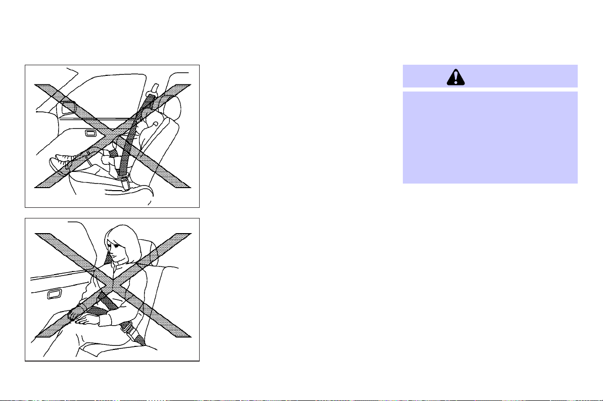
O Do not ride in a moving vehicle when the
seatback is reclined. This can be dangerous. The shoulder belt will not be
against your body. In an accident, you
could be thrown into it and receive neck
or other serious injuries. You could also
slide under the lap belt and receive serious internal injuries.
O For the most effective protection when
the vehicle is in motion, the seat should
be upright. Always sit well back in the
seat with both feet on the floor and adjust the seat belt properly.
1-12 Safety — Seats, seat belts and supplemental restraint system
WARNING
SSS0292
Front seat
Fastening the seat belts
1. Adjust the seat. See “Seats” earlier in
this section.
2. Slowly pull the seat belt out of the retractor and insert the tongue into the
buckle until it clicks.
O The retractor is designed to lock during
a sudden stop or on impact. A slow
pulling motion will permit the belt to
move, and allow you some freedom of
movement in the seat.
O If the seat belt cannot be pulled from
its fully retracted position, firmly pull
Page 29
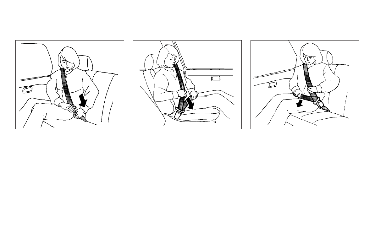
Rear seat
SSS0293
the belt and release it. Then smoothly
pull the belt out of the retractor.
Front seat
SSS0290
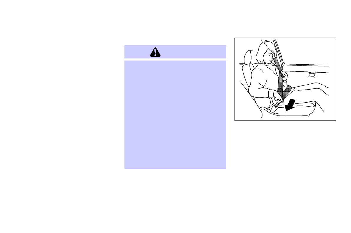
3. Position the lap belt portion low and
snug on the hips as shown.
4. Pull the shoulder belt portion toward
the retractor to take up extra slack.
Make sure the shoulder belt is routed
over your shoulder and across your
chest.
The front passenger and rear seat belts
have a locking mechanism for child restraint installation. It is referred to as the
automatic locking mode or child restraint
mode.
When the automatic locking mechanism is
Safety — Seats, seat belts and supplemental restraint system 1-13
Rear seat
SSS0291A
activated the seat belt cannot be extended again until the seat belt tongue is
detached from the buckle and fully retracted. Once retracted, the seat belt is in
the emergency locking mode. For additional information, see “Child restraints”
later in this section.
The automatic locking mode should be
used only for child restraint installation.
During normal seat belt use by an occupant, the locking mode should not be activated. If it isactivated it maycause uncomfortable seat belt tension. It can also
change the operation of the front passenger air bag. See “Front passenger air
Page 30
bag and status light” later in this section.
WARNING
When fastening the seat belts, be certain
that seatbacks are completely secured in
the latched position. If they are not completely secured, passengers may be injured
in an accident or sudden stop.
To increase your confidence in the seat
belts, check the operation as follows:
O grasp the shoulder belt and pull for-
ward quickly. The retractor should lock
and restrict further belt movement.
If the retractor does not lock during this
check or if you have any question about
belt operation, see an INFINITI dealer.
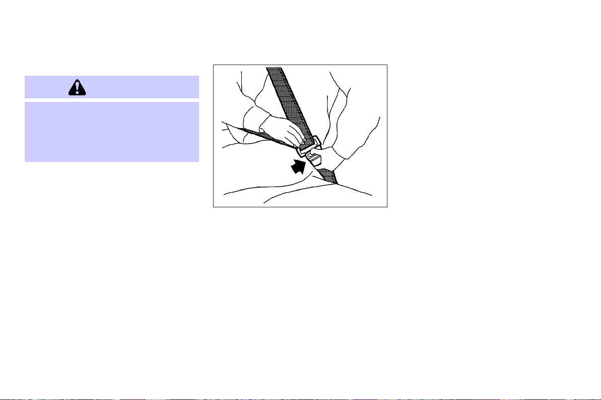
SSS0326
Unfastening the seat belts
To unfasten the belt, push the button on
the buckle. The seat belt will automatically retract.
Checking seat belt operation
Your seat belt retractors are designed to
lock belt movement by two separate
methods:
O when the belt is pulled quickly from
the retractor.
O when the vehicle slows down rapidly.
1-14 Safety — Seats, seat belts and supplemental restraint system
Page 31

SPA1836 SSS0294A
Center of rear seat
Selecting correct set of seat belts:
The center seat belt buckle is identified
by the CENTER mark
belt tongue can be fastened only into the
center seat belt buckle.
A
q
. The center seat
Shoulder belt height adjustment
(front seats)
The shoulder belt anchor height should
be adjusted to the position best for you.
See “Precautions on seat belt usage” earlier in this section.
WARNING
O After adjustment, release the adjust-
ment button and try to move the
shoulder belt anchor up and down to
make sure it issecurely fixed inposition.
O The shoulder belt anchor height should
be adjusted to the position best for you.
Failure to doso may reduce theeffectiveness of the entire restraint system and
increase the chance or severity of injury
in an accident.
Safety — Seats, seat belts and supplemental restraint system 1-15
To adjust, push the button
move the shoulder belt anchor to the desired position, so that the belt passes
over the center of the shoulder. The belt
should be away from your face and neck,
but not falling off of your shoulder. Release the button to lock the shoulder belt
anchor into position.
A
q
, and then
SEAT BELT EXTENDERS
If, because of body size or driving position, it is not possible to properly fit the
lap-shoulder belt and fasten it, an extender is available. The extender adds approximately 8 in (200 mm) of length and
Page 32

CHILD RESTRAINTS
may be used for either the driver or front
passenger seating position. See an
INFINITI dealer for assistance if the extender is required.
WARNING
O Only INFINITI belt extenders, made by
the same company which made the
original equipment seat belts, should be
used with the INFINITI seat belts.
O Adults and children who can use the
standard seat belt should not use an extender. Such unnecessary use could result in serious personal injury in the
event of an accident.
O Never use seat belt extenders to install
child restraints. If the child restraint is
not secured properly, the child could be
seriously injured in a collision or a
sudden stop.
Then brush it, wipe with a cloth and allow it to dry in the shade. Do not allow
the seat belts to retract until they are
completely dry.
O If dirt builds up in the shoulder belt
guide of the seat belt anchors, the
seat belts may retract slowly. Wipe the
shoulder belt guide with a clean, dry
cloth.
O Periodically check to see that the seat
belt and the metal components such as
buckles, tongues, retractors, flexible
wires and anchors work properly. If
loose parts, deterioration, cuts or
other damage on the webbing are
found, the entire belt assembly should
be replaced.
SEAT BELT MAINTENANCE
O
To clean the seat belt webbings, apply a
mild soap solution or any non-caustic
solution recommended for gently
cleaning cloth upholstery or carpets.
1-16 Safety — Seats, seat belts and supplemental restraint system
SSS0099
PRECAUTION ON CHILD
RESTRAINTS
WARNING
O Infants and small children should al-
ways be placed in an appropriate child
restraint while riding in the vehicle. Failure to use a child restraint can result in
serious injury or death.
O Infants and small children should never
be carried on your lap. It is not possible
Page 33

SSS0100
for even the strongest adult to resist the
forces of a severe accident. The child
could be crushed between the adult and
parts of the vehicle. Also, do not put the
same seat belt around both your child
and yourself.
O Even with the INFINITI Advanced Air Bag
System, never install a rear-facing child
restraint in the front seat. An inflating
supplemental front air bag could seriously injure or kill your child. A rearfacing child restraint must only be used
in the rear seat.
O INFINITI recommends that the child re-
straint be installed in the rear seat. According to accident statistics, children
are safer when properly restrained in the
rear seat than in the front seat. If you
must install a front facing child restraint
in the front seat, see “Child restraint installation using the seat belts” in this
section.
O Improper use or improper installation of
a child restraint can increase the risk or
severity of injury for both the child and
other occupants of the vehicle and can
lead to serious injury or death in an accident.
O Follow all of the child restraint manufac-
turer’s instructions for installation and
use. When purchasing a child restraint,
be sure to select one which will fit your
child and vehicle. It may not be possible
to properly installsome types ofchild restraints in your vehicle.
O If the child restraint is not anchored
properly, the risk of a child being injured
in a collision or a sudden stop greatly increases.
O Child restraint anchor points are de-
signed to withstand only those loads imposed by correctly fitted child restraints.
Under no circumstances are they to be
used for adult seat belts or harnesses.
O Adjustable seatbacks should be posi-
tioned to fit the child restraint, but as
upright as possible.
O After attaching the child restraint, test it
before you place the child in it. Push it
from side to side while holding the seat
near the LATCH attachment or by the
seat belt path. Try to tug it forward and
check to see if the belt holds the restraint in place. The child restraint
should not move more than 1 in (25 mm).
If the restraint is not secure, tighten the
belt as necessary, or put the restraint in
another seat and test it again. You may
need to try a differentchild restraint. Not
all child restraints fit in all types of vehicles.
O When your child restraint is not in use,
keep it secured with the LATCH System
or a seat belt to prevent it from being
thrown around in case of a sudden stop
or accident.
Safety — Seats, seat belts and supplemental restraint system 1-17
Page 34

restraint, keep the following points in
CAUTION
Remember that a child restraint left in a
closed vehicle can become very hot. Check
the seating surface and buckles before placing your child in the child restraint.
This vehicle is equipped with a universal
child restraint lower anchor system, referred to as the Lower Anchors and
Tethers for CHildren System or LATCH.
Some child restraints include two rigid or
webbing-mounted attachments that can
be connected to these lower anchors. For
details, see “Lower Anchors and Tethers
for CHildren System (LATCH)” in this section.
If you do not have a LATCH compatible
child restraint, the vehicle seat belts can
be used. See “Child restraint installed using the seat belts” later in this section. In
general, child restraints are also designed
to be installed with the lap portion of a
lap/shoulder seat belt.
Several manufacturers offer child restraints for infants and small children of
various sizes. When selecting any child
mind:
O Choose only a restraint with a label
certifying that it complies with Federal
Motor Vehicle Safety Standard 213 or
Canadian Motor Vehicle Safety Standard 213.
O Check the child restraint in your ve-
hicle to be sure it is compatible with
the vehicle’s seat and seat belt
system.
O If the child restraint is compatible with
your vehicle, place your child in the
child restraint and check the various
adjustments to be sure the child restraint is compatible with your child.
Choose a child restraint that is designed for your child’s height and
weight. Always follow all recommended procedures.
All U.S. states and Canadian provinces or
territories require that infants and small
children be restrained in anapproved child
restraint at all times while the vehicle is
being operated.
1-18 Safety — Seats, seat belts and supplemental restraint system
Lower Anchors and Tethers for
CHildren SYSTEM (LATCH)
Your vehicle is equipped with special anchor points that are used with Lower Anchors and Tethers for CHildren System
(LATCH) compatible child restraints. This
system may also be referred to as the
ISOFIX or ISOFIX compatible system. With
this system, you do not have to use a vehicle seat belt to secure the child restraint.
The LATCH anchor points are provided to
install child restraints in the rear outboard seating positions only. Do not attempt to install a child restraint in the
center position using the LATCH anchors.
Page 35

LATCH label location
SSS0567
LATCH lower anchor point
locations
The LATCH anchors are located at the rear
of the seat cushion near the seatback. A
label is attached to the seatback to help
you locate the LATCH anchors.
LATCH lower anchor location (Type A)
SSS0659
WARNING
O Attach LATCH compatible child re-
straints only at the locations shown in
the illustration. If a child restraint is not
secured properly, your child could be seriously injured or killed in an accident.
O Do not secure a child restraint in the
center rear seating position using the
LATCH anchors. The child restraint will
not be secured properly.
Safety — Seats, seat belts and supplemental restraint system 1-19
LATCH lower anchor location (Type B)
SSS0637
O Child restraint anchor points are de-
signed to withstand only those loads imposed by correctly fitted child restraints.
Under no circumstance are they to be
used for adult seat belts or harnesses.
Page 36

LATCH webbing-mounted attachment
Installing child restraint LATCH
anchor attachments
LATCH compatible child restraints include
two rigid or webbing-mounted attachments that can be connected to two anchors located at certain seating positions
in your vehicle. With this system, you do
not have to use a vehicle seat belt to secure the child restraint. Check your child
restraint for a label stating that it is compatible with LATCH. This information may
also be in the instructions provided by
the child restraint manufacturer.
SSS0643
LATCH rigid attachment
LATCH child restraints generally require
the use of a top tether strap. See “Top
tether strap child restraint” in this section
for installation instructions.
When installing a child restraint, carefully
read and follow the instructions in this
manual and those supplied with the child
restraint. See “Child restraint installation
using LATCH” in this section.
1-20 Safety — Seats, seat belts and supplemental restraint system
SSS0644
SSS0568
TOP TETHER STRAP CHILD
RESTRAINT
If the manufacturer of your child restraint
requires the use of a top tether strap, it
must be secured to an anchor point.
WARNING
Child restraint anchor pointsare designed to
withstand only those loads imposed by correctly fitted child restraints. Under no circumstances are they to be used for adult
Page 37

seat belts or harnesses.
CHILD RESTRAINT INSTALLATION
USING LATCH
Top tether anchor point locations
Anchor points are located on the rear parcel shelf.
Installing top tether strap
First, secure the child restraint with the
seat belt or LATCH (rear outboard seat positions only), as applicable.
Flip up the anchor cover from the anchor
point which is located directly behind the
child seat. Position the top tether strap
over the top of the seatback and secure it
to the tether anchor bracket that provides
the straightest installation. Tighten the
strap according to the manufacturer’s instructions to remove any slack.
If you have any questions when installing
a top tether strap child restraint on the
rear seat, consult your INFINITI dealer for
details.
WARNING
O Attach LATCH compatible child re-
straints only at the locations shown. For
the LATCH lower anchor locations, see
“Lower Anchors and Tethers for CHildren
System (LATCH)” in this section. If a
child restraint is not secured properly,
your child could be seriously injured or
killed in an accident.
O The LATCH anchors are designed to
withstand only those loads imposed by
correctly fitted child restraints. Underno
circumstance are they to be used for
adult seat belts or harnesses.
O Inspect the lower anchors by inserting
your fingers into the lower anchor area
and feeling tomake sure there areno obstructions over the LATCH anchors, such
as seat belt webbingor seat cushion material. The child restraint will not be secured properly if the LATCH anchors are
obstructed.
Safety — Seats, seat belts and supplemental restraint system 1-21
Front facing — step 3
SSS0645
Front-facing
Follow these steps to install a front-facing
child restraint using LATCH:
1. If your vehicle is equipped with rear
power seat adjustment, adjust the rear
outboard seats to the uplight and rearmost position.
O Do not move the rear outboard seats
with the child restraints attached to
them.
2. Position the child restraint on the
seat. Always follow the child restraint
manufacturer’s instructions.
Page 38

proper child restraint fit, try another
seating position or a different child restraint.
Front facing − step 3
SSS0646
3. Secure the child restraint anchor attachments to the LATCH lower anchors.
4. The back of the child restraint should
be secured against the vehicle seatback. If necessary, adjust or remove
the head restraint to obtain the correct child restraint fit. See “Head restraint adjustment” in this section. If
the head restraint is removed, store it
in a secure place. Be sure to install
the head restraint when the child restraint is removed. If the seating position does not have an adjustable head
restraint and it is interfering with the
1-22 Safety — Seats, seat belts and supplemental restraint system
Front facing − step 5
SSS0647
5. For child restraints that are equipped
with webbing mounted attachments,
remove any additional slack from the
anchor attachments. Press downward
and rearward firmly in the center of
the child restraint with your knee to
compress the vehicle seat cushion and
seatback while tightening the webbing
of the anchor attachments.
6. If the child restraint is equipped with
a top tether strap, route the top tether
strap and secure the tether strap to
the tether anchor point. See “Top
tether strap child restraint” in this
section.
Page 39

straint. Not all child restraints fit in all
types of vehicles.
8. Check to make sure the child restraint
is properly secured prior to each use.
If the child restraint is loose, repeat
steps 4 through 7.
Front facing − step 7
SSS0638
7. Before placing the child in the child
restraint, hold child restraint near the
LATCH attachment and use force to
push the child restraint from side to
side, and tug it forward to make sure
that it is securely held in place. It
should not move more than 1 in (25
mm). If it does move more than 1 in
(25 mm), pull again on the anchor attachments to further tighten the child
restraint. If you are unable to properly
secure the restraint, move the restraint to another seating position and
try again, or try a different child re-
Rear facing − step 3
SSS0648
Rear-facing
Follow these steps to install a rear-facing
child restraint using LATCH:
1. If your vehicle is equipped with rear
power seat adjustment, adjust the rear
outboard seats to the uplight and rearmost position.
O Do not move the rear outboard seats
with the child restraints attached to
them.
2. Position the child restraint on the
seat. Always follow the child restraint
manufacturer’s instructions.
Safety — Seats, seat belts and supplemental restraint system 1-23
Page 40

3. Secure the child restraint anchor at-
Rear facing − step 3
tachments to the LATCH lower anchors.
SSS0649
Rear facing − step 4
4. For child restraints that are equipped
with webbing mounted attachments,
remove any additional slack from the
anchor attachments. Press downward
and rearward firmly in the center of
the child restraint with your hand to
compress the vehicle seat cushion and
seatback while tightening the webbing
of the anchor attachments.
1-24 Safety — Seats, seat belts and supplemental restraint system
SSS0639
Rear facing − step 5
SSS0650
5. Before placing the child in the child
restraint, hold the child restraint near
the LATCH attachment and use force to
push the child restraint from side to
side, and tug it forward to make sure
that it is securely held in place. It
should not move more than 1 in (25
mm). If it does move more than 1 in
(25 mm), pull again on the anchor attachments to further tighten the child
restraint. If you are unable to properly
secure the restraint, move the restraint to another seating position and
try again, or try a different child re-
Page 41

straint. Not all child restraints fit in all
types of vehicles.
6. Check to make sure the child restraint
is properly secured prior to each use.
If the child restraint is loose, repeat
steps 4 through 5.
SSS0100
CHILD RESTRAINT INSTALLATION
USING THE SEAT BELTS
WARNING
O Even with the INFINITI Advanced Air Bag
System, never install a rear-facing child
restraint in the front passenger seat.
Supplemental front air bags inflate with
great force. A rear-facing child restraint
could be struck by the supplemental
front air bag in a crash and could seri-
ously injure or kill your child.
O INFINITI recommends that child re-
straints be installed in the rear seat.
However, if you must install a forward
facing child restraint in the front passenger seat, move the passenger seat to
the rearmost position. Also, be sure the
front passenger air bag status light is illuminated to indicate the passenger air
bag is OFF. See “Front passenger air bag
and status light” in this section for details.
O The three-point seat belt in your vehicle
is equipped with an automatic locking
mode retractor which must be used
when installing a child restraint.
O Failure to use the retractor’s locking
mode will result inthe child restraint not
being properly secured. The restraint
could tip over or otherwise be unsecured
and cause injury to the child in a sudden
stop or collision. Also, it can change the
operation of the front passenger air bag.
See “Front passenger air bag and status
light” in this section.
Safety — Seats, seat belts and supplemental restraint system 1-25
Page 42

O A child restraint with a top tether strap
should not be used in the front passenger seat.
The instructions in this section apply to
child restraint installation using the vehicle seat belts in the rear seat or the
front passenger seat.
Front facing (front passenger seat) — step 2
Front-facing
Follow these steps to install a front-facing
child restraint using the vehicle seat belt
in the rear seat or in the front passenger
seat:
1. If your vehicle is equipped with rear
power seat adjustment, adjust the rear
outboard seats to the uplight and rearmost position.
O Do not move the rear outboard seats
with the child restraints attached to
them.
2. If you must install a child restraint in
1-26 Safety — Seats, seat belts and supplemental restraint system
SSS0640
the front seat, it should be placed in a
front-facing direction only. Move the
seat to the rearmost position. Child restraints for infants must be used in the
rear-facing direction and therefore
must not be used in the front seat.
3. Position the child restraint on the
seat. Always follow the child restraint
manufacturer’s instructions.
The back of the child restraint should
be secured against the seatback. If
necessary, adjust or remove the head
restraint to obtain the correct child restraint fit. See “Head restraint adjustment” in this section.
If the head restraint is removed, store
it in a secure place. Be sure to install
the head restraint when the child restraint is removed. If the seating position does not have an adjustable head
restraint and it is interfering with the
proper child restraint fit, try another
seating position or a different child restraint.
Page 43

Front facing — step 4
SSS0360B
4. Route the seat belt tongue through the
child restraint and insert it into the
buckle until you hear and feel the
latch engage. Be sure to follow the
child restraint manufacturer’s instructions for belt routing.
Front facing — step 5
SSS0651
5. Pull the shoulder belt until the belt is
fully extended. At this time, the seat
belt retractor is in the automatic locking mode (child restraint mode). It reverts to emergency locking mode
when the seat belt is fully retracted.
Safety — Seats, seat belts and supplemental restraint system 1-27
Front facing — step 6
SSS0652
6. Allow the seat belt to retract. Pull up
on the shoulder belt to remove any
slack in the belt.
Page 44

straint. Not all child restraints fit in all
types of vehicles.
10. Check that the retractor is in the automatic locking mode by trying to pull
more seat belt out of the retractor. If
you cannot pull any more belt webbing out of the retractor, the retractor
is in the automatic locking mode.
11. Check to make sure the child restraint
is properly secured prior to each use.
If the seat belt is not locked, repeat
steps 4 through 9.
7. Remove any additional slack from the
Front facing — step 7
seat belt; press downward and rearward firmly in the center of the child
restraint with your knee to compress
the vehicle seat cushion and seatback
while pulling up on the seat belt.
8. If the child restraint is equipped with
a top tether strap, route the top tether
strap and secure the tether strap to
the tether anchor point (rear seat installation only). See “Top tether strap
child restraint” in this section. Do not
install child restraints equipped with a
top tether strap to seating positions
that do not have a top tether anchor.
SSS0653
Front facing — step 9
9. Before placing the child in the child
restraint, hold the child restraint near
the seat belt path and use force to
push the child restraint from side to
side, and tug it forward to make sure
that it is securely held in place. It
should not move more than 1 in (25
mm). If it does move more than 1 in
(25 mm), pull again on the shoulder
belt to further tighten the child restraint. If you are unable to properly
secure the restraint, move the restraint to another seating position and
try again, or try a different child re-
1-28 Safety — Seats, seat belts and supplemental restraint system
SSS0641
Page 45

therefore must not be used in the front
seat. Position the child restraint on
the seat. Always follow the restraint
manufacturer’s instructions.
Front facing — step 12
SSS0481
12. If the child restraint is installed in the
front passenger seat, push the ignition switch to the ON position. The
front passenger air bag status light
should illuminate. If this light is
not illuminated, see “Front passenger
air bag and status light” in this section. Move the child restraint to an-
other seating position. Have the
system checked by an INFINITI dealer.
After the child restraint is removed and
the seat belt is fully retracted, the automatic locking mode (child restraint mode)
is canceled.
SSS0100
Rear-facing
Follow these steps to install a rear-facing
child restraint using the vehicle seat belt
in the rear seat:
1. If your vehicle is equipped with rear
power seat adjustment, adjust the rear
outboard seats to the uplight and rearmost position.
O Do not move the rear outboard seats
with the child restraints attached to
them.
2. Child restraints for infants must be
used in the rear-facing direction and
Safety — Seats, seat belts and supplemental restraint system 1-29
Page 46

3. Route the seat belt tongue through the
Rear facing — step 3
child restraint and insert it into the
buckle until you hear and feel the
latch engage. Be sure to follow the
child restraint manufacturer’s instructions for belt routing.
SSS0654
Rear facing — step 4
4. Pull the shoulder belt until the entire
belt is fully extended. At this time, the
seat belt retractor is in the automatic
locking mode (child restraint mode). It
reverts to emergency locking mode
when the seat belt is fully retracted.
1-30 Safety — Seats, seat belts and supplemental restraint system
SSS0655
Rear facing — step 5
DDS0656
5. Allow the seat belt to retract. Pull up
on the shoulder belt to remove any
slack in the belt.
Page 47

Rear facing — step 6
SSS0657
6. Remove any additional slack from the
child restraint; press downward and
rearward firmly in the center of the
child restraint with your hand to compress the vehicle seat cushion and
seatback while pulling up on the seat
belt.
Rear facing — step 7
SSS0658
7. Before placing the child in the child
restraint, hold the child restraint near
the seat belt path and use force to
push the child restraint from side to
side, and tug it forward to make sure
that it is securely held in place. It
should not move more than 1 in (25
mm). If it does move more than 1 in
(25 mm), pull again on the shoulder
belt to further tighten the child restraint. If you are unable to properly
secure the restraint, move the restraint to another rear seating position
and try again, or try a different child
restraint. Not all child restraints fit in
Safety — Seats, seat belts and supplemental restraint system 1-31
all types of vehicles.
8. Check that the retractor is in the automatic locking mode by trying to pull
more seat belt out of the retractor. If
you cannot pull any more seat belt
webbing out of the retractor, the retractor is in the automatic locking
mode.
9. Check to make sure that the child restraint is properly secured prior to
each use. If the belt is not locked, repeat steps 4 through 7.
After the child restraint is removed and
the seat belt fully retracted, the automatic
locking mode (child restraint mode) is
canceled.
Page 48

BOOSTER SEATS
SSS0099
PRECAUTIONS ON BOOSTER SEATS
WARNING
O Infants and small children should al-
ways be placed in an appropriate child
restraint while riding in the vehicle. Failure to use a child restraint or booster
seat can result in serious injury or death.
O Infants and small children should never
be carried on your lap. It is not possible
for even the strongest adult to resist the
forces of a severe accident. The child
could be crushed between the adult and
parts of the vehicle. Also, do not put the
same seat belt around both your child
and yourself.
O INFINITI recommends that the booster
seat be installed in the rear seat. According to accident statistics, children
are safer when properly restrained inthe
rear seat than in the front seat. If you
must install a booster seat in the front
seat, see “Booster seat installation” in
this section.
O A booster seat must only be installed in
a seating position that has a
lap/shoulder belt. Failure to use a threepoint type seat belt with a booster seat
can result in a serious injury in sudden
stop or collision.
O Improper use or improper installation of
a booster seat can increase the risk or
severity of injury for both the child and
other occupants of the vehicle and can
lead to serious injury or death in an
accident.
O Do not use towels, books, pillows or
other items in place of a booster seat.
Items such as these may move during
normal driving or a collision and result
in serious injury or death. Booster seats
are designed to be used with a
lap/shoulder belt. Booster seats are designed to properly route the lap and
shoulder portions of the seat belt over
the strongest portions of a child’s body
to provide the maximum protection
during a collision.
O Follow all of the booster seat manufac-
turer’s instructions for installation and
use. When purchasing a boosterseat, be
sure to select one which will fit your
child and vehicle. It may not be possible
to properly install some types of booster
seats in your vehicle.
O If the booster seat and seat belt is not
used properly, the risk of a child being
injured in a collision or a sudden stop
greatly increases.
O Adjustable seatbacks should be posi-
tioned to fit the booster seat, but as up-
1-32 Safety — Seats, seat belts and supplemental restraint system
Page 49

right as possible.
O After placing the child in the booster
seat and fastening the seat belt, make
sure the shoulder portion of the belt is
away from the child’s face and neck and
the lap portion of the belt does not cross
the abdomen.
O Do not put the shoulder belt behind the
child or under the child’s arm. If you
must install a booster seat in the front
seat, see “Booster seat installation”
later in this section.
O When your booster seat is not in use,
keep it secured with a seat belt to prevent it from being thrown around in case
of a sudden stop or accident.
CAUTION
Remember that a booster seat left in a
closed vehicle can become very hot. Check
the seating surface and buckles before
placing your child in the booster seat.
LRS0455 LRS0453
Booster seats of various sizes are offered
by several manufacturers. When selecting
any booster seat, keep the following
points in mind:
O Choose only a booster seat with a
label certifying that it complies with
Federal Motor Vehicle Safety Standard
213 or Canadian Motor Vehicle Safety
Standard 213.
Safety — Seats, seat belts and supplemental restraint system 1-33
O Check the booster seat in your vehicle
to be sure it is compatible with the vehicle’s seat and seat belt system.
O Make sure the child’s head will be
properly supported by the booster
seat or vehicle seat. The seat back
must be at or above the center of the
child’s ears. For example, if a low back
booster seat
seat back must be at or above the
center of the child’s ears. If the seat
back is lower than the center of the
child’s ears, a high back booster seat
2
should be used.
q
1
is chosen, the vehicle
q
Page 50

or the front passenger seat.
BOOSTER SEAT INSTALLATION
WARNING
INFINITI recommends that booster seats be
installed in the rear seat. However, if you
must install a booster seat in the front passenger seat, move the passenger’s seat to
the rearmost position.
LRS0464 SSS0640
O If the booster seat is compatible with
your vehicle, place your child in the
booster seat and check the various
adjustments to be sure the booster
seat is compatible with your child. Always follow all recommended procedures.
All U.S. states and Canadian provinces or
territories require that infants and small
children be restrained in anapproved child
restraint at all times while the vehicle is
being operated.
The instructions in this section apply to
booster seat installation in the rear seats
Do not use the lap/shoulder belt automatic
locking mode when using a booster seat
with the seat belts.
Follow these steps to install a booster
seat in the rear seat or in the front passenger seat:
1-34 Safety — Seats, seat belts and supplemental restraint system
CAUTION
1. If your vehicle is equipped with rear
power seat adjustment, adjust the rear
outboard seats to the uplight and rearmost position.
O Do not move the rear outboard seats
with the booster seat attached to
them.
2. If you must install a booster seat in the
front seat, move the seat to the rearmost position.
3. Position the booster seat on the seat.
Only place it in a front facing direction. Always follow the booster seat
manufacturer’s instructions.
Page 51

Center position
LRS0451
4. The booster seat should be positioned
on the vehicle seat so that it is stable.
If necessary, adjust or remove the
head restraint to obtain the correct
booster seat fit. See “Head restraint”
earlier in this section. If the head restraint is removed, store it in a secure
place. Be sure to install the head restraint when the booster seat is removed. If the seating position does
not have an adjustable head restraint
and it is interfering with the proper
booster seat fit, try another seating
position or a different booster seat.
Outboard position
LRS0452
5. Position the lap portion of the seat
belt low and snug on the child’s hips.
Be sure to follow the booster seat
manufacturer’s instructions for adjusting the belt routing.
6. Pull the shoulder belt portion of the
seat belt toward the retractor to take
up extra slack. Be sure the shoulder
belt is positioned across the top,
middle portion of the child’s shoulder.
Be sure to follow the booster seat
manufacturer’s instructions for adjusting the belt routing.
Safety — Seats, seat belts and supplemental restraint system 1-35
Front seat
LRS0454
7. Follow the warnings, cautions and instructions for properly fastening a seat
belt shown in the “Three-point seat
belt with retractor” earlier in this section.
Page 52

SUPPLEMENTAL RESTRAINT SYSTEM
PRECAUTIONS ON SUPPLEMENTAL
RESTRAINT SYSTEM
This Supplemental Restraint System (SRS)
section contains important information
concerning the driver and passenger front
impact supplemental air bags (INFINITI
Advanced Air Bag System), front seat
side-impact supplemental air bags, curtain side-impact air bags and front seat
pre-tensioner seat belts.
Supplemental front air bag system: The
INFINITI advanced air bag system can help
SSS0481
8. If the booster seat is installed in the
front passenger seat, push the ignition switch to the ON position. The
front passenger air bag status light
may or may not illuminate depending on the size of the child and
the type of booster seat used. See
“Front passenger air bag and status
light” in this section.
cushion the impact force to the face and
chest of the driver and front passenger in
certain frontal collisions.
Supplemental side air bag system: This
system can help cushion the impact force
to the chest and pelvis area of the driver
and front passenger in certain side impact
collisions. The front seat side-impact
supplemental air bags are designed to inflate on the side where the vehicle is impacted.
Supplemental curtain side-impact air bag
system: This system can help cushion the
impact force to the head of occupants in
front and rear outboard seating positions
in certain side impact collisions. The curtain side-impact air bags are designed to
1-36 Safety — Seats, seat belts and supplemental restraint system
inflate on the side where the vehicle is
impacted.
These supplemental restraint systems are
designed to supplement the crash protection provided by the driver and passenger
seat belts and are not a substitute for
them. Seat belts should always be correctly worn and the occupant seated a
suitable distance away from the steering
wheel, instrument panel and door finishers. (See “Seat belts” earlier in this
section for instructions and precautions
on seat belt usage.)
The supplemental air bags operate only
when the ignition switch is in the ON position.
After pushing the ignition switch to the ON
position, the supplemental air bag
warning light illuminates. The supplemental air bag warning light will turn off
after about 7 seconds if the systems are
operational.
Page 53

SSS0131
SSS0132
WARNING
O The supplemental front air bags ordi-
narily will not inflate in the event of a
side impact, rear impact, rollover, or
lower severity frontal collision. Always
wear your seat belts to help reduce the
risk or severity of injury in various kinds
of accidents.
O The front passenger air bag will not in-
flate if the passenger air bag status light
is lit or if the front passenger seat is unoccupied. See “Front passenger air bag
and status light” later in this section.
O The seat belts and the supplemental
front air bags are most effective when
you are sitting well back and upright in
the seat. Supplemental front air bags inflate with great force. Even with the
INFINITI advanced air bag system, if you
are unrestrained, leaning forward, sitting sideways or out of position in any
way, you are at greater risk of injury or
death in a crash. You may also receive
serious or fatal injuries from the supple-
Safety — Seats, seat belts and supplemental restraint system 1-37
Page 54

mental front air bag if you are up against
it when it inflates. Always sit back
against the seatback and as far-away as
practical from the steering wheel or instrument panel. Always use the seat
belts.
O The driver and front passenger seat belt
buckles are equipped with sensors that
detect if the seat belts are fastened. The
air bag system monitors the severityof a
collision and seat belt usage then inflates the air bags. Failure to properly
wear seat belts can increase the risk or
severity of injury in an accident.
O The front passenger seat is equipped
with an occupant classification sensor
(pressure sensor) that turns the front
passenger air bag OFF under some conditions. This sensor is only used in this
seat. Failure to be properly seated and
wearing the seat belt can increase the
risk or severity of injury in an accident.
See “Front Passenger air bag and status
light” later in this section.
O Keep hands on the outside of the
steering wheel. Placing them inside the
steering wheel rim could increase the
risk of injury if thesupplemental front air
bag inflates.
SSS0007
SSS0006
1-38 Safety — Seats, seat belts and supplemental restraint system
Page 55

SSS0008
SSS0099
WARNING
O Never let children ride unrestrained or
extend their hands or face out of the
window. Do not attempt to hold them in
your lap or arms. Some examples of dangerous riding positions are shown in the
illustrations.
O Children may be severely injured or
killed when the supplemental front air
bags, side air bags or curtain sideimpact air bags inflate if they are not
properly restrained. Pre-teens and children should be properly restrained in
the rear seat, if possible.
O Even with the INFINITI Advanced Air Bag
System, never install a rear facing child
restraint in the front seat. An inflating
supplemental front air bag could seriously injure or kill your child. See “Child
restraints” earlier in this section for details.
SSS0009
SSS0100
Safety — Seats, seat belts and supplemental restraint system 1-39
Page 56

SSS0059A
SSS0188A
1-40 Safety — Seats, seat belts and supplemental restraint system
SSS0140
SSS0162
SSS0159
WARNING
Supplemental side air bag and curtain sideimpact air bag:
O The supplemental side air bag and cur-
tain side-impact air bag ordinarily will
not inflate in the event of a frontal impact, rear impact, rollover or lower severity side collision. Always wear your
seat belts to help reduce the risk or severity of injury in various kinds of accidents.
Page 57

O The seat belts, the supplemental side air
bags and curtain side-impact air bags
are most effective when you are sitting
well back and upright in the seat. The
side air bag and curtain side-impact air
bag inflate with great force. Do not allow
anyone to place their hand, leg or face
near the side air bag on the side of the
seatback of the front seat or near the
side roof rails. Do not allow anyone sitting in the front seats or rear outboard
seats to extend their hand out of the
window or lean against the door. Some
examples of dangerous riding positions
are shown in the previous illustrations.
O When sitting inthe rear seat, donot hold
onto the seatback of the frontseat. If the
supplemental side air bag inflates, you
may be seriously injured. Be especially
careful with children,who shouldalways
beproperlyrestrained.Someexamplesof
dangerous riding positions are shown in
the illustrations.
O Do not use seat covers on the front seat-
backs. They may interfere with supple-
mental side air bag inflation.
Safety — Seats, seat belts and supplemental restraint system 1-41
Page 58

1. Crash zone sensor
2. Supplemental front air bag modules
(INFINITI advanced air bags)
3. Supplemental side air bag modules
4. Occupant classification system control
unit
5. Occupant classification sensor
6. Supplemental curtain side-impact air
bags
7. Supplemental curtain side-impact air
bag modules
8. Diagnosis sensor unit
1-42 Safety — Seats, seat belts and supplemental restraint system
SSS0480
9. Satellite sensors
10. Seat belt pre-tensioner retractor
INFINITI ADVANCED AIR BAG
SYSTEM (front seats)
This vehicle is equipped with the INFINITI
advanced air bag system for the driver
and front passenger seats. This system is
designed to meet certification requirements under U.S. regulations. It is also
permitted in Canada. However, all of the
information, cautions and warnings in this
manual still apply and must be followed.
The driver supplemental air bag is located
in the center of the steering wheel; the
front passenger supplemental air bag is
mounted in the instrument panel above
the glove box. The front air bags are designed to inflate in higher severity frontal
collisions, although they may inflate if the
forces in another type of collision are
similar to those of a higher severity
frontal impact. They may not inflate in
certain frontal collisions. Vehicle damage
(or lack of it) is not always an indication
of proper supplemental air bag operation.
The INFINITI advanced air bag system has
dual stage inflators for both the driver
and passenger air bags. The system moni-
Page 59

tors information from the crash zone sensor, the diagnosis sensor unit, seat belt
buckle switches, occupant classification
sensor (pressure sensor) and passenger
seat belt tension sensor. Inflator operation is based on the severity of a collision
and whether the seat belts are being
used. For the front right passenger, it additionally monitors the weight of an occupant or object on the seat and seat belt
tension. Based on information from the
sensors, only one front air bag may inflate in a crash, depending on the crash
severity and whether the front occupants
are belted or unbelted. Additionally, the
front right passenger air bag may be automatically turned OFF under some conditions, depending on the weight detected
on the passenger seat and how the seat
belt is used. If the front passenger air bag
is OFF, the passenger air bag status light
will be illuminated (if the seat is unoccupied, the light will not be illuminated, but
the air bag will be off). See “Front passenger air bag and status light” later in
this section for further details. One front
air bag inflating does not indicate improper performance of the system.
If you have any questions about your air
bag system, contact an INFINITI dealer. If
you are considering modification of your
vehicle due to a disability, you may also
contact an INFINITI dealer. Contact information is contained in the front of this
Owner’s Manual.
When the supplemental front air bag inflates, a fairly loud noise may be heard,
followed by release of smoke. This smoke
is not harmful and does not indicate a
fire. Care should be taken not to inhale it,
as it may cause irritation and choking.
Those with a history of a breathing condition should get fresh air promptly.
Supplemental front air bags, along with
the use of seat belts, help to cushion the
impact force on the face and chest of the
front occupants. They can help save lives
and reduce serious injuries. However, an
inflating front air bag may cause facial
abrasions or other injuries. Front air bags
do not provide restraint to the lower
body.
Even with INFINITI advanced air bags, seat
belts should be correctly worn and the
driver and passenger seated upright as
far as practical away from the steering
wheel or instrument panel. The supplemental front air bags inflate quickly in or-
Safety — Seats, seat belts and supplemental restraint system 1-43
der to help protect the front occupants.
Because of this, the force of the front air
bag inflating can increase the risk of injury if the occupant is too close to, or is
against the air bag module during inflation.
The air bag will deflate quickly after a collision.
The supplemental front air bags operate
only when the ignition switch is in the ON
position.
After pushing the ignition switch to the ON
position, the supplemental air bag
warning light illuminates. The supplemental air bag warning light will turn off
after about 7 seconds if the system is operational.
Page 60

follow all instructions in this manual concerning the use of seats,seat belts and child
restraints can increase the risk or severity of
injury in an accident.
Status light:
The front passenger air bag status light
is located on the overhead console.
The light operates as follows:
Front passenger air bag status light
SSS0481
Front passenger air bag and
status light
WARNING
The front passenger air bag is designed to
automatically turn OFF under some conditions. Read this section carefully to learn
how it operates. Proper use of the seat, seat
belt and child restraints is necessary for
most effective protection. Failure to
O Unoccupied passenger seat: The
O Passenger seat occupied by a small
O Occupied passenger seat and the pas-
Front passenger air bag:
The front passenger air bag is designed to
is OFF and the front passenger
air bag is OFF and will not inflate in a
crash.
adult, child or child restraint as outlined in this section: The
nates to indicate that the front passenger air bag is OFF and will not inflate in a crash.
senger meets the conditions outlined
in this section: The light
indicate that the front passenger air
bag is operational.
1-44 Safety — Seats, seat belts and supplemental restraint system
illumi-
is OFF to
automatically turn OFF when the vehicle is
operated under some conditions as described below as permitted by U.S. regulations. If the front passenger air bag is
OFF, it will not inflate in a crash. The
driver air bag and other air bags in your
vehicle are not part of this system.
The purpose of the regulation is to help
reduce the risk of injury or death from an
inflating air bag to certain front passenger
seat occupants, such as children, by requiring the air bag to be automatically
turned OFF. Certain sensors are used to
meet the requirements.
One sensor used is the occupant classification sensor (pressure sensor). It is in
the bottom of the front passenger seat
cushion and is designed to detect an occupant and objects on the seat by weight.
It works together with seat belt sensors
described later. For example, if a child is
in the front passenger seat, the advanced
air bag system is designed to turn the
passenger air bag OFF. Also, if a child restraint of the type specified in the regulations is on the seat, its weight and the
child’s weight can be detected and cause
the air bag to turn OFF. The occupant classification sensor operation can vary de-
Page 61

pending on the front passenger seat belt
sensors.
The front passenger seat belt sensors are
designed to detect if the seat belt is
buckled and the amount of tension on the
seat belt, such as when it is in the automatic locking mode (child restraint mode).
Based on the weight on the seat detected
by the occupant classification sensor and
the belt tension detected on the seat belt,
the advanced air bag system determines
whether the front passenger air bag
should be automatically turned OFF as required by regulations.
Front passenger seat adult occupants who
are properly seated and using the seat
belt as outlined in this manual should not
cause the passenger air bag to be automatically turned OFF. For small adults it
may be turned OFF, however, if the occupant takes his/her weight off the seat
cushion (for example, by not sitting upright, by sitting on an edge of the seat, or
by otherwise being out of position), this
could cause the sensor to turn the air bag
OFF. In addition, if the occupant improperly uses the seat belt in the automatic
locking mode (child restraint mode), this
could cause the air bag to be turned OFF.
Always be sure to be seated and wearing
the seat belt properly for the most effective protection by the seat belt and
supplemental air bag.
INFINITI recommends that pre-teens and
children be properly restrained in a rear
seat. INFINITI also recommends that appropriate child restraints and booster
seats be properly installed in a rear seat.
If this is not possible, the occupant classification sensor and seat belt sensors
are designed to operate as described
above to turn the front passenger air bag
OFF for specified child restraints as required by regulations. Failing to properly
secure child restraints and to use the automatic locking mode (child restraint
mode) may allow the restraint to tip or
move in an accident or sudden stop. This
can also result in the passenger air bag
inflating in a crash instead of being OFF.
See “Child restraints” earlier in this section for proper use and installation.
If the front passenger seat is not occupied, the passenger air bag is designed
not to inflate in a crash. However, heavy
objects placed on the seat could result in
air bag inflation, because of the object’s
weight detected by the occupant classification sensor. Other conditions could also
result in air bag inflation, such as if a
Safety — Seats, seat belts and supplemental restraint system 1-45
child is standing on the seat, or if two
children are on the seat, contrary to the
instructions in this manual. Always be
sure that you and all vehicle occupants
are seated and restrained properly.
Using the passenger air bag status light,
you can monitor when the front passenger air bag is automatically turned OFF
with the seat occupied. The light will not
illuminate when the front passenger seat
is unoccupied.
If an adult occupant is in the seat but the
passenger air bag status light is illuminated (indicating that the air bag is OFF),
it could be that the person is a small
adult, or is not sitting on the seat properly or is not using the seat belt properly.
If a child restraint must be used in the
front seat, the passenger air bag status
light may or may not be illuminated, depending on the size of the child and the
type of child restraint being used. If the
air bag status light is not illuminated (indicating that the air bag might inflate in a
crash), it could be that the child restraint
or seat belt is not being used properly.
Make sure that the child restraint is installed properly, the seat belt is used
properly and the occupant is positioned
Page 62

properly. If the air bag status light is still
not illuminated, reposition the occupant
or child restraint in a rear seat.
If the passenger air bag status light will
not illuminate even though you believe
that the child restraint, the seat belts and
the occupant are properly positioned, the
system may be sensing an unoccupied
seat (in which case the air bag is OFF).
Your INFINITI dealer can check that the
system is OFF by using a special tool.
However, until you have confirmed with
your dealer that your air bag is working
properly, reposition the occupant or child
restraint in a rear seat.
The INFINITI advanced air bag system and
passenger air bag status light will take a
few seconds to register a change in the
passenger seat status. For example, if a
large adult who is sitting in the front passenger seat exits the vehicle, the passenger air bag status light will change from
OFF to ON for a few seconds and then to
OFF. This is normal system operation and
does not indicate a malfunction.
If a malfunction occurs in the front passenger air bag system, the supplemental
air bag warning light
meter and gauges area will blink. Have
, located in the
the system checked by an INFINITI dealer.
Other supplemental front air bag
precautions
O Do not place any objects on the steering
wheel pad or on the instrument panel.
Also, do not place any objects between
any occupant and the steering wheel or
instrument panel. Such objects may become dangerous projectiles and cause
injury if the supplemental front air bag
inflates.
O Immediately after inflation, several front
air bag system components will be hot.
Do not touch them; you may severely
burn yourself.
O No unauthorized changes should be
made to any components or wiring of the
supplemental air bag system. This is to
prevent accidental inflation of the
1-46 Safety — Seats, seat belts and supplemental restraint system
WARNING
supplemental air bag or damage to the
supplemental air bag system.
O Do not make unauthorized changes to
your vehicle’s electrical system, suspension system or front end structure. This
could affect proper operation of the
supplemental front air bag system.
O Tampering with the supplemental air
bag system may result in serious personal injury. Tampering includes
changes to the steering wheel and the
instrument panel assembly by placing
material over the steeringwheel pad and
above the instrument panel or by installing additional trim material around the
air bag system.
O Modifying or tampering with the front
passenger seat may result in serious
personal injury. For example, do not
change the front seats by placing material on the seat cushion or by installing
additional trim material, such as seat
covers, on the seat. Additionally, do not
stow any objects under the front passenger seat or the seat cushion and
Page 63

seatback. Such objects may interfere
with the proper operation of the occupant classification sensor (pressuresensor).
O No unauthorized changes should be
made to any components or wiringof the
seat belt system. This may affect the
supplemental front air bag system. Tampering with the seat belt system may result in serious personal injury.
O Work around and on the supplemental
front air bag system should be done by
an INFINITI dealer. Installation of electrical equipment should also bedone by an
INFINITI dealer. The yellow and orange
Supplemental Restraint System (SRS)
wiring and connectors should not be
modified or disconnected. Unauthorized
electrical test equipment and probing
devices should not be used on the air
bag system.
O A cracked windshield should be re-
placed immediately by a qualified repair
facility. A cracked windshield could affect the function of the supplemental air
bag system.
O The SRS wiring harness connectors are
yellow and orange for easy
identification.
When selling your vehicle, we request
that you inform the buyer about the
supplemental front air bag system and
guide the buyer to the appropriate sections in this Owner’s Manual.
SSS0521
SUPPLEMENTAL SIDE AIR BAG AND
CURTAIN SIDE-IMPACT AIR BAG
SYSTEM
The supplemental side air bags are located in the outside of the seatback of
the front seats. The supplemental curtain
side-impact air bags are located in the
side roof rails. These systems are designed to meet voluntary guidelines to
help reduce the risk of injury to out-ofposition occupants. However, all of the in-
formation, cautions and warnings in this
manual still apply and must be followed.
The supplemental side air bags and cur-
Safety — Seats, seat belts and supplemental restraint system 1-47
Page 64

tain side-impact air bags are designed to
inflate in higher severity side collisions,
although they may inflate if the forces in
another type of collision are similar to
those of a higher severity side impact.
They are designed to inflate on the side
where the vehicle is impacted. They may
not inflate in certain side collisions on the
side where the vehicle is impacted. Vehicle damage (or lack of it) is not always
an indication of proper supplemental side
air bag and curtain side-impact air bag
operation.
When the supplemental side air bag and
curtain side-impact air bag inflate, a fairly
loud noise may be heard, followed by release of smoke. This smoke is not harmful
and does not indicate a fire. Care should
be taken not to inhale it, as it may cause
irritation and choking. Those with a history of a breathing condition should get
fresh air promptly.
Supplemental side air bags, along with
the use of seat belts, help to cushion the
impact force on the chest and pelvis of
the front occupants. Curtain side-impact
air bags help to cushion the impact force
to the head of occupants in the front and
rear outboard seating positions. They can
help save lives and reduce serious injuries. However, an inflating side air bag
and curtain side-impact air bag may
cause abrasions or other injuries. Supplemental side air bags and curtain sideimpact air bags do not provide restraint
to the lower body.
The seat belts should be correctly worn
and the driver and passenger seated upright as far as practical away from the
side air bag. Rear seat passengers should
be seated as far away as practical from
the door finishers and side roof rails. The
side air bags and curtain side-impact air
bag inflate quickly in order to help protect
the out-of-position occupants. Because of
this, the force of the side air bag and curtain side-impact air bag inflating can increase the risk of injury if the occupant is
too close to, or is against, these air bag
modules during inflation. The side air bag
and curtain side-impact air bag will deflate quickly after the collision is over.
After pushing the ignition switch to the ON
position, the supplemental air bag
warning light illuminates. The air bag
warning light willturn off after about7 seconds if the systems are operational.
1-48 Safety — Seats, seat belts and supplemental restraint system
WARNING
O Do not place any objects near the seat-
back of the front seats. Also, do not
place any objects (an umbrella, bag,
etc.) between the front door finisher and
the front seat. Such objects may become
dangerous projectiles and cause injury if
the supplemental side air bag inflates.
O Right after inflation, several side air bag
and curtain side-impact air bag system
components will be hot. Do not touch
them; you may severely burn yourself.
O No unauthorized changes should be
made to any components or wiring of
this side air bag and curtain air bag
system. This is to prevent accidental inflation of the side air bag and curtain
side-impact air bag or damage to the
side air bag and curtain side-impact air
bag system.
O Do not make unauthorized changes to
your vehicle’s electrical system, suspension system or side panel. This could affect proper operation of the supple-
Page 65

mental side air bag and curtain sideimpact air bag system.
O Tampering with the supplemental air
bag system may result in serious personal injury. For example, do not change
the front seat by placing material near
the seatback or by installing additional
trim material, such as seat covers,
around the side air bag.
O Work around and on the side air bag and
curtain side-impact air bag system
should be done by an INFINITI dealer. Installation of electrical equipment should
also be done by an INFINITI dealer. The
SRS wiring harnesses* should not be
modified or disconnected. Unauthorized
electrical test equipment and probing
devices should not be used on the side
air bag system.
* The SRS wiring harnesses connectors
are yellow and orange for easy
identification.
When selling your vehicle, we request
that you inform the buyer about the side
air bag and curtain side-impact air bag
system and guide the buyer to the appropriate sections in this Owner’s Manual.
PRE-TENSIONER SEAT BELT
SYSTEM (front seats)
WARNING
O The pre-tensioner seat belt cannot be re-
used after activation.It must bereplaced
together with the retractor and buckle
as a unit.
O If the vehicle becomesinvolved in a fron-
tal collision but the pre-tensioner is not
activated, be sure to have the pretensioner system checked and, if necessary, replaced by an INFINITI dealer.
O No unauthorized changes should be
made to any components or wiringof the
pre-tensioner seat belt system. This is to
prevent accidental activation of the pretensioner seat belt or damageto the pretensioner seat belt operation. Tampering with the pre-tensioner seat belt
system may result in serious personal
injury.
Safety — Seats, seat belts and supplemental restraint system 1-49
O Work around and on the pre-tensioner
system should be done by an INFINITI
dealer. Installation of electrical equipment should also be done by an INFINITI
dealer. Unauthorized electrical test
equipment and probing devices should
not be used on the pre-tensioner seat
belt system.
O If you need to dispose of the pre-
tensioner or scrap the vehicle, contact
an INFINITI dealer. Correct pre-tensioner
disposal procedures are set forth in the
appropriate INFINITI Service Manual. Incorrect disposal procedures could cause
personal injury.
The front seat pre-tensioner seat belt system activates in conjunction with the
supplemental air bag systems. Working
with the seat belt retractor, it helps
tighten the seat belt when the vehicle becomes involved in certain types of collisions, helping to restrain front seat occupants.
The pre-tensioner is encased with the
seat belt’s retractor. These seat belts are
used the same as conventional seat belts.
Page 66

When the pre-tensioner seat belt activates, smoke is released and a loud noise
may be heard. The smoke is not harmful,
but care should be taken not to inhale it
as it may cause irritation and choking.
Those with a history of a breathing condition should get fresh air promptly.
If any abnormality occurs in the pretensioner system, the supplemental air
bag warning light
will flash intermittently or will turn on for
7 seconds and remain on after the ignition switch has been pushed to the ON
position. In this case, the pre-tensioner
seat belt may not function properly. They
must be checked and repaired. Take your
vehicle to the nearest INFINITI dealer.
When selling your vehicle, we request
that you inform the buyer about the pretensioner seat belt system and guide the
buyer to the appropriate sections in this
Owner’s Manual.
will not come on,
SUPPLEMENTAL AIR BAG WARNING
LABELS
Warning labels about the supplemental
front air bag and supplemental sideimpact air bag systems are placed in the
vehicle as shown in the illustration.
1
q
SRS air bag
The warning labels are located on the surface of the sun visors.
2
q
SRS side-impact air bag
The warning label is located on the side
of the passenger’s side center pillar.
1-50 Safety — Seats, seat belts and supplemental restraint system
SSS0330 SPA1097
SUPPLEMENTAL AIR BAG WARNING
LIGHT
The supplemental air bag warning light,
displaying
monitors the circuits of the supplemental
front air bag, supplemental side air bag
and curtain side-impact air bag systems,
and pre-tensioner seat belt. The circuits
monitored by the supplemental air bag
warning light are the diagnosis sensor
unit, satellite sensors, crash zone sensor,
front air bag modules, side air bag modules, curtain side-impact air bag modules,
in the instrument panel,
Page 67

and all related wiring, and pre-tensioner
seat belt.
After pushing the ignition switch to the
ON position, the supplemental air bag
warning light illuminates. The supplemental air bag warning light will turn off after
about 7 seconds if the system is operational.
If any of the following conditions occur,
the supplemental front air bag, supplemental side air bag and curtain sideimpact air bag systems, and pre-tensioner
seat belt need servicing:
O The supplemental air bag warning
light remains on after approximately 7
seconds after pushing the ignition
switch to the ON position.
O The supplemental air bag warning
light flashes intermittently.
O The supplemental air bag warning
light does not come on at all.
Under these conditions, the supplemental
front air bags, supplemental side air
bags, curtain side-impact air bags and/or
pre-tensioner seat belt may not operate
properly. They must be checked and repaired. Take your vehicle to the nearest
INFINITI dealer.
WARNING
If the supplemental air bag warning light is
on, it could mean that the supplemental
front air bag, supplemental side air bag, curtain side-impact air bag systems and/or pretensioner seat belt will not operate in an accident. To help avoid injury to yourself or
others, have your vehicle checked by a
dealer as soon as possible.
REPAIR AND REPLACEMENT
PROCEDURE
The supplemental front air bags, supplemental side air bags, curtain side-impact
air bags and pre-tensioner seat belt are
designed to activate on a one-time-only
basis. As a reminder, unless it is damaged, the supplemental air bag warning
light will remain illuminated after inflation
has occurred. Repair and replacement of
these systems should be done only by an
INFINITI dealer.
When maintenance work is required on
the vehicle, the supplemental front air
bags, side air bags, curtain side-impact
air bags, related parts and pre-tensioner
Safety — Seats, seat belts and supplemental restraint system 1-51
seat belt should be pointed out to the
person conducting the maintenance. The
ignition switch should always be in the
LOCK position when working under the
hood or inside the vehicle.
WARNING
O Once a supplemental front air bag, side
air bag orcurtain side-impact airbag has
inflated, the air bag module will not
function again and must be replaced.
Additionally, if any of the supplemental
front air bags inflate, the activated pretensioner seat belt must also be replaced. The air bag module and pretensioner seat belt system should be replaced by an INFINITI dealer. The air bag
modules and pre-tensioner seat belt
system cannot be repaired.
O The supplemental front air bag, side air
bag and curtain side-impact air bag systems and pre-tensioner seat belt system
should be inspected by an INFINITI
dealer if there is any damage to the front
end or side portion of the vehicle.
Page 68

O If you need to dispose of the supplemen-
tal air bag, pre-tensioner seat belt
system or scrap the vehicle, contact an
INFINITI dealer.
Correct supplemental air bag and pretensioner seat belt system disposal procedures are set forth in the appropriate
INFINITI Service Manual. Incorrect disposal procedures could cause personal
injury.
1-52 Safety — Seats, seat belts and supplemental restraint system
Page 69

MEMO
Safety — Seats, seat belts and supplemental restraint system 1-53
Page 70

2 Instruments and controls
Cockpit ........................................................... 2-2
Instrument panel .............................................. 2-3
Meters and gauges........................................... 2-4
Speedometer and odometer ........................ 2-5
Tachometer ................................................. 2-5
Engine coolant temperature gauge .............. 2-6
Fuel gauge .................................................. 2-6
Meter/ring illumination and needle
sweep ......................................................... 2-7
Compass .......................................................... 2-8
Warning/indicator lights and audible
reminders ........................................................ 2-11
Checking bulbs........................................... 2-11
Warning lights ........................................... 2-12
Indicator lights........................................... 2-17
Audible reminders ..................................... 2-19
Dot matrix liquid crystal display ..................... 2-20
Indicators for operation ............................. 2-21
Security systems ............................................ 2-22
Vehicle security system ............................. 2-22
INFINITI Vehicle Immobilizer System .......... 2-24
Windshield wiper and washer switch .............. 2-25
Rear window and outside mirror defroster
switch............................................................. 2-26
Headlight and turn signal switch .................... 2-26
Xenon headlights (if so equipped)............. 2-26
Headlight switch........................................ 2-27
Turn signal switch...................................... 2-31
Fog light switch ......................................... 2-31
Hazard warning flasher switch........................ 2-32
Horn ............................................................... 2-32
Heated seats (Rear seats) (if so equipped) ..... 2-33
Climate controlled seats (Front seats) (if so
equipped)....................................................... 2-34
Lane departure warning (LDW) switch (if so
equipped) ....................................................... 2-35
SNOW mode switch (if so equipped)............... 2-36
Vehicle Dynamic Control (VDC) off switch ....... 2-36
Clock .............................................................. 2-37
Adjusting the time..................................... 2-37
Power outlet ................................................... 2-37
Cigarette lighter and ashtrays ........................ 2-38
Front ......................................................... 2-38
Rear .......................................................... 2-39
Storage........................................................... 2-39
Cup holders .............................................. 2-39
Sunglasses holder .................................... 2-41
Glove box .................................................. 2-41
Page 71

Console box .............................................. 2-42
Coat hooks................................................ 2-43
Cargo net (if so equipped)......................... 2-44
Windows......................................................... 2-44
Power windows ......................................... 2-44
Sunroof .......................................................... 2-46
Automatic sunroof..................................... 2-46
Rear control cancel switch (if so equipped) .... 2-48
Rear sunshade (if so equipped) ...................... 2-48
Interior lights ................................................ 2-49
Map lights................................................. 2-49
Rear personal lights .................................. 2-50
Interior light control switch ....................... 2-50
Vanity mirror lights ......................................... 2-51
Trunk light....................................................... 2-51
HomeLink Universal Transceiver .................... 2-52
Programming HomeLink
Programming HomeLink
........................... 2-52
for Canadian
customers ................................................. 2-54
Operating HomeLink
Universal
Transceiver................................................ 2-54
Programming trouble diagnosis................. 2-54
Clearing the programmed information ....... 2-55
Reprogramming a single HomeLink
button ....................................................... 2-55
If your vehicle is stolen ............................. 2-55
Page 72

COCKPIT
1. Instrument brightness control switch
(P.2-30)
2. Outside mirror remote control (P.3-24)
3. Adaptive Front lighting System (AFS)
switch (if so equipped) (P.2-29)
2-2 Instruments and controls
SSI0090
4. Vehicle Dynamic Control (VDC) OFF
switch (P.2-36)
5. Headlight, fog light and turn signal
switch (P.2-26)
6. Steering-wheel-mounted controls (Left
side)
— ENTER switch (P.4-5, P.4-43)
— BACK switch (P.4-43)
— TALK switch (P.4-68)/Phone switch
(P.4-61)
— Volume control switches (P.4-44)
— Source select switch (P.4-43)
7. Windshield wiper and washer switch
(P.2-25)
8. Steering-wheel-mounted controls
(Right side)
— Cruise control switches (P.5-19)
— Intelligent Cruise Control (ICC)
switches (if so equipped) (P.5-21)
9. Hood release handle (P.5-17)
10. Trunk lid release switch (P.3-18)
11. Lane Departure Warning (LDW) switch
(if so equipped) (P.2-35, P.5-15)
12. Intelligent Key port (P.5-8)
13. Tilting/telescopic steering wheel
switch (P.3-22)
14. Steering wheel
— Horn (P.2-32)
— Driver supplemental air bag
(P.1-36)
Page 73

INSTRUMENT PANEL
1. Side ventilator (P.4-23)
2. Meters and gauges (P.2-4)
3. Center ventilator (P.4-23)
4. Security indicator light (P.2-24)
SSI0091
5. Hazard warning flasher switch
(P.2-32)
6. Automatic climate control system
(P.4-24)
7. Center multi-function control panel
— Navigation system (if so equipped)
— Vehicle information and setting but-
tons (P.4-6)
— Phone system (P.4-60)
— Audio system (P.4-29)
8. Front passenger supplemental air bag
(P.1-36)
9. Fuse box cover (P.8-26)
10. Parking brake pedal
— Parking (P.5-45)
— Maintenance (P.8-25)
11. Push-button ignition switch (P.5-8)
12. Clock (P.2-37)
13. Cigarette lighter and ashtrays (P.2-38)
14. Audio system (P.4-29)
15. Glove box lid release button (P.2-41)
16. Bluetooth
module (P.4-60)/DVD drive for navigation system (if so equipped)
17. Trunk release power cancel switch
(P.3-19)
in-vehicle phone
Instruments and controls 2-3
Page 74

METERS AND GAUGES
*: The needle indicators in the speedom-
eter, tachometer, engine coolant temperature gauge and fuel gauge may
move slightly after the ignition switch is
pushed to the LOCK position. This is not
a malfunction.
SSI0092
1. Engine coolant temperature gauge*
2. Tachometer*
3. Warning/indicator lights
4. Speedometer*
5. Fuel gauge*
2-4 Instruments and controls
6. Meter illumination control knob
7. Dot matrix liquid crystal display
8. Odometer/twin trip odometer
9. Change/reset knob for twin trip
odometer
Page 75

SIC2760 SIC2761
SPEEDOMETER AND ODOMETER
Speedometer
The speedometer indicates vehicle speed.
Odometer/twin trip odometer
The odometer
2
are displayed when the ignition switch
q
is in the ON position.
The odometer records the total distance
the vehicle has been driven.
The twin trip odometer records the dis-
tance of individual trips.
1
and twin trip odometer
q
Changing the display:
3
Pushing the TRIP/RESET knob
the display as follows:
TRIP A → TRIP B → TRIP A
Resetting the trip odometer:
Push the TRIP/RESET knob for more than 1
second to reset the currently displayed
trip odometer to zero.
Average fuel economy and distance to
empty information is also available. Refer
to “How to use status button” in the
“4. Monitor, climate, audio, phone and
voice recognition systems” section later
in this manual.
q
changes
TACHOMETER
The tachometer indicates engine speed in
revolutions per minute (RPM). Do not rev
the engine into the red zone
q
A
.
CAUTION
When engine speed approaches the red
zone, shift to a higher gear. Operating the
engine in thered zone may causeserious engine damage.
Instruments and controls 2-5
Page 76

CAUTION
If the gauge indicates engine coolant temperature near the hot (H) end of the normal
range, reduce vehicle speed to decrease
temperature. If gauge is over the normal
range, stop the vehicle as soon as safely
possible. If the engine is overheated, continued operation of the vehicle may seriously
damage the engine. See “If your vehicle
overheats” in the “6. In case of emergency”
SIC2762 SIC2763
section for immediate action required.
ENGINE COOLANT TEMPERATURE
GAUGE
The gauge indicates the engine coolant
temperature.
The engine coolant temperature is in the
normal range when the gauge needle
points within the zone
lustration.
The engine coolant temperature will vary
with the outside air temperature and driving conditions.
A
q
shown in the il-
2-6 Instruments and controls
FUEL GAUGE
The gauge indicates the approximate fuel
level in the tank.
The gauge may move slightly during braking, turning, acceleration, or going up or
down hill.
The gauge needle returns to E (Empty) after the ignition switch is pushed to LOCK.
Refill the fuel tank before the gauge registers “E” (Empty).
The low fuel warning light
when the fuel tank is getting low. Refuel
A
q
comes on
Page 77

as soon as it is convenient, preferably before the gauge reaches “E”. There will be
a small reserve of fuel in the tank when
the fuel gauge needle reaches “E”.
The
is located on the passenger’s side of the
vehicle.
indicates that the fuel-filler door
CAUTION
O If the vehicle runs out of fuel, the
malfunction indicator light (MIL)
may come on. Refuel as soon as possible. After a few driving trips, the
lamp should turn off. If the lamp
remains on after a few driving trips,have
the vehicle inspected by an INFINITI
dealer.
O For additional information, see “Mal-
function indicator lamp (MIL)” later in
this section.
SIC2874
METER/RING ILLUMINATION AND
NEEDLE SWEEP
The ring illumination surrounding meters
and gauges illuminates when the driver’s
door is closed after getting into the vehicle with the Intelligent Key carried in.
When the engine is started, the indicator
needles will sweep in the speedometer
and tachometer and the ring illumination
will be brightened gradually.
Meter illumination control knob
The meter illumination control knob
q
operates when the headlight switch is in
the AUTO (not lighting) or OFF position
with the ignition switch in the ON position.
To adjust the brightness of the meters,
push the control knob several times until
the desired brightness is achieved.
To turn the ring illumination and needle
sweep on and off, push the control knob
and hold it for 1 second.
1
Instruments and controls 2-7
Page 78

COMPASS
SIC3181
If the display reads “C”, calibrate the
compass by driving the vehicle in 3 complete circles at less than 5 MPH (8 km/h).
You can also calibrate the compass by
driving your vehicle on your everyday
route. The compass will be calibrated
once it has tracked 3 complete circles.
To turn on and off the compass manually,
push the
tion switch is in the ON position.
switch
A
q
while the igni-
When the ignition switch is pushed to the
ON position, the compass display
indicate the direction of the vehicle’s
heading.
q
B
will
2-8 Instruments and controls
Page 79

Zone map
SIC0611B
Zone variation change procedure
The difference between magnetic north
and geographical north is known as variance. In some areas, this difference can
sometimes be great enough to cause
false compass readings. Follow these instructions to set the variance for your particular location if this happens:
1. Push the
seconds. The current zone number will
appear in the display.
2. Find your current location and variance number on the zone map.
3. Push the
the new zone number appears in the
display, then release the switch. After
you release the switch, the display
will show a compass direction within a
few seconds.
O If the compass deviates from the cor-
rect indication soon after repeated adjustment, have the compass checked
at an INFINITI dealer.
O The compass may not indicate the cor-
rect compass point in tunnels or while
driving up or down a steep hill.
(The compass returns to the correct
compass point when the vehicle
switch for more than 3
switch repeatedly until
Instruments and controls 2-9
Page 80

moves to an area where the geomagnetism is stabilized.)
CAUTION
O Do not install a ski rack, antenna, etc.,
which are attached to the vehicle by
means of a magnet. They affect the operation of the compass.
O When cleaning the mirror, use a paper
towel or similar material dampened with
glass cleaner. Do not spray glass
cleaner directly on the mirror as it may
cause the liquid cleaner to enter the mirror housing.
2-10 Instruments and controls
Page 81

WARNING/INDICATOR LIGHTS AND
AUDIBLE REMINDERS
All-Wheel Drive (AWD) warning light (AWD
models)
or
Automatic transmission check warning light
or Brake warning light
Charge warning light Seat belt warning light
Door open warning light Supplemental air bag warning light Malfunction Indicator Light (MIL)
Engine oil pressure warning light
Intelligent Cruise Control (ICC) system warning
light (Orange; if so equipped)
Intelligent Key warning light Cruise main switch indicator light (Green)
Low fuel warning light
Anti-lock Braking System (ABS)
warning light
CHECKING BULBS
Apply the parking brake and push the ignition switch to the ON position without
starting the engine. The following lights
will come on:
Low tire pressure warning light Front passenger air bag status light
Low washer fluid warning light High beam indicator light (Blue)
Preview Function warning light (Orange; if so
equipped)
Rear Active Steer warning light (if so
equipped)
Adaptive Front lighting System (AFS) indicator
light (if so equipped)
Automatic transmission position indicator
light
Cruise set switch indicator light
, or , , , ,
, , ,
The following lights come on briefly and
then go off (if so equipped):
, or , , , ,
Intelligent Cruise Control (ICC) system MAIN
switch indicator light (Green; if so equipped)
Intelligent Cruise Control (ICC) system set
switch indicator light (if so equipped)
Lane Departure Warning (LDW) system indicator light (Orange; if so equipped)
Slip indicator light
Turn signal/hazard indicator lights
Vehicle Dynamic Control (VDC) off indicator
light
, , ,
If any light does not come on, it may indicate a burned-out bulb or an open circuit
in the electrical system. Have the system
checked by an INFINITI dealer.
Instruments and controls 2-11
Page 82

WARNING LIGHTS
All-Wheel Drive (AWD)
warning light (AWD models)
The warning light comes on when
the ignition switch is pushed to ON. It
turns off soon after the engine is started.
If the AWD system malfunctions, or the diameter of the front and the rear wheels
are different, the warning light will either
remain illuminated or blink. See “AllWheel Drive (AWD)” in the “5. Starting
and driving” section.
CAUTION
O If the warning light comes on while
driving there may bea malfunction in the
AWD system. Reduce the vehicle speed
and have your vehicle checked by an
INFINITI dealer as soon as possible.
O If the AWD warning light blinks on when
you are driving:
- blinks rapidly (about twice a second):
Pull off the road in a safe area, and
2-12 Instruments and controls
idle the engine. The driving mode will
change to 2WD to prevent the AWD
system from malfunctioning. If the
warning light turns off, you can drive
again.
- blinks slowly (about once every 2 seconds):
Pull off the road in a safe area, and
idle the engine. Check that all tire
sizes are the same, tire pressure is
correct and tires are not worn.
O If the warning light is still on after the
above operations, have your vehicle
checked by an INFINITI dealer as soon as
possible.
or Anti-lock Braking
System (ABS)
warning light
When the ignition switch is in the ON position, the Anti-lock Braking System (ABS)
warning light illuminates and then turns
off. This indicates the ABS is operational.
If the ABS warning light illuminates while
the engine is running, or while driving, it
may indicate the ABS is not functioning
properly. Have the system checked by an
INFINITI dealer.
If an ABS malfunction occurs, the antilock funcition is turned off. The brake
system then operates normally, but
without anti-lock assistance. See “Brake
system” in the “5. Starting and driving”
section.
Automatic transmission
check warning light
When the ignition switch is pushed to the
ON position, the light comes on for 2 seconds. If the light comes on at any other
time, it may indicate the transmission is
not functioning properly. Have your
INFINITI dealer check and repair the transmission.
or Brake warning
light
This light functions for both the parking
brake and the foot brake systems.
Parking brake indicator:
When the ignition switch is in the ON position, the light comes on when the parking brake is applied.
Page 83

Low brake fluid warning light:
When the ignition switch is in the ON position, the light warns of a low brake fluid
level. If the light comes on while the engine is running with the parking brake not
applied, stop the vehicle and perform the
following:
1. Check the brake fluid level. Add brake
fluid as necessary. See “Brake fluid” in
the “8. Maintenanceand do-it-yourself”
section.
2. If the brake fluid level is correct, have
the warning system checked by an
INFINITI dealer.
Anti-lock Braking System (ABS) warning
indicator:
When the parking brake is released and
the brake fluid level is sufficient, if both
the brake warning light and the Anti-lock
Braking System (ABS) warning light illuminate, it may indicate the ABS is not
functioning properly. Have the brake
system checked, and if necessary repaired, by an INFINITI dealer promptly.
Avoid high-speed driving and abrupt
braking. (See “Anti-lock Braking System
(ABS) warning light” earlier in this section.)
WARNING
O Your brake system may not be working
properly if the warning light is on.
Driving could be dangerous. If you judge
it to be safe, drive carefully to the
nearest service station for repairs. Otherwise, have your vehicle towed because
driving it could be dangerous.
O Pressing the brake pedal withthe engine
stopped and/or low brakefluid level may
increase your stopping distance and
braking will require greater pedal effort
as well as pedal travel.
O If the brake fluid level is below the
minimum or MIN mark on the brake fluid
reservoir, do not drive until the brake
system has been checked at an INFINITI
dealer.
Charge warning light
If the light comes on while the engine is
running, it may indicate the charging system is not functioning properly. Turn the
engine off and check the alternator belt. If
the belt is loose, broken, missing or if the
light remains on, see an INFINITI dealer
immediately.
CAUTION
Do not continue driving if the alternator belt
is loose, broken or missing.
Door open warning light
This light comes on when any of the
doors are not closed securely while the
ignition switch is in the ON position.
Engine oil pressure warning
light
This light warns of low engine oil pressure. If the light flickers or comes on during normal driving, pull off the road in a
safe area, stop the engine immediately
and call an INFINITI dealer or other authorized repair shop.
The engine oil pressure warning light is
not designed to indicate a low oil level.
Use the dipstick to check the oil level. See
“Engine oil” in the “8. Maintenance and
do-it-yourself” section.
Instruments and controls 2-13
Page 84

CAUTION
Running the engine with the engine oil pressure warning light on could cause serious
damage to the engine almost immediately.
Such damage isnot covered by warranty.Turn
off the engine as soon as it is safe to do so.
Intelligent Cruise Control
(ICC) system warning light
(Orange; if so equipped)
This light comes on if there is a malfunction in the Intelligent Cruise Control (ICC)
system.
Intelligent Key warning
light
After the ignition switch is pushed to the
ON position, this light comes on for about
2 seconds and then turns off.
This light warns of a malfunction with the
electrical steering lock system or the Intelligent Key system.
If the light comes on while the engine is
stopped, it may be impossible to free the
steering lock or to start the engine. If the
light comes on while the engine is run-
2-14 Instruments and controls
ning, you can drive the vehicle. However
in these cases, contact an INFINITI dealer
for repair as soon as possible.
Low fuel warning light
This light comes on when the fuel in the
tank is getting low. Refuel as soon as it is
convenient, preferably before the fuel
gauge reaches “E” (Empty).
There will be a small reserve of fuel remaining in the tank when the fuel gauge
needle reaches “E” (Empty).
Low tire pressure warning
light
Your vehicle is equipped with a tire pressure
monitoring system (TPMS) that monitors the
tire pressure of all tires except the spare.
The low tire pressure warning light warns
of low tire pressure or indicates that the
TPMS is not functioning properly.
After the ignition switch is turned ON, this
light illuminates for about 1 second and
turns off.
Low tire pressure warning:
If the vehicle is being driven with low tire
pressure, the warning light will illuminate.
The LOW PRESSURE information will also
be indicated on the display.
When the low tire pressure warning light
illuminates, you should stop and adjust
the tire pressure to the recommended
COLD tire pressure shown on the Tire and
Loading Information label.
The low tire pressure warning light does
not automatically turn off when the tire
pressure is adjusted. After the tire is inflated to the recommended pressure, the
vehicle must be driven at speeds above
16 MPH (25 km/h) to activate the TPMS
and turn off the low tire pressure warning
light. Use a tire pressure gauge to check
the tire pressure.
For additional information, see “Tire pressure monitoring system (TPMS)” in the “5.
Starting and driving” section and in the
“6. In case of emergency” section.
TPMS malfunction:
If the TPMS is not functioning properly,
the low tire pressure warning light will
flash for approximately 1 minute when the
ignition switch is pushed ON. The light
will remain on after the 1 minute. Have
the system checked by an INFINITI dealer.
For additional information, see “Tire pressure monitoring system (TPMS)” in the “5.
Starting and driving” section.
Page 85

WARNING
O If the light does not illuminate with the
ignition switch pushed ON, have the vehicle checked by an INFINITI dealer as
soon as possible.
O If the light illuminates while driving,
avoid sudden steering maneuvers or
abrupt braking, reduce vehicle speed,
pull off the road to a safe location and
stop the vehicle as soon as possible. Serious vehicle damage could occur and
may lead to an accident and could result
in serious personal injury. Check the tire
pressure for all four tires. Adjust the tire
pressure to the recommended COLD tire
pressure shown on the Tire and Loading
Information label to turn the low tire
pressure warning light OFF. If the light
still comes on while driving after adjusting the tire pressure, a tire may be
flat. If you have a flat tire, replace it with
a spare tire as soon as possible.
O Immediately after tire rotation is per-
formed, tire pressure will not be indi-
cated on the display and the TPMS will
not function. Resetthe system by driving
the vehicle at over 25 MPH (40 km/h) for
approximately 10 minutes. If tire pressure is notindicated after performingthe
resetting procedure above, contact an
INFINITI dealer as soon as possible.
O When a spare tire is mounted or a wheel
is replaced, tire pressure willnot be indicated, the TPMSwill not functionand the
low tire pressure warninglight will flash.
Contact your INFINITI dealer as soon as
possible for tire replacement and/orsystem resetting.
O Replacing tires with those not originally
specified by INFINITI could affect the
proper operation of the TPMS.
CAUTION
O The TPMS is not a substitute for the
regular tire pressure check. Be sure
tocheck the tire pressure regularly.
O If the vehicle is being driven at speeds of
less than 16 MPH (25 km/h), the TPMS
may not operate correctly.
O Be sure to install the specified size of
tires to the front and rear.
Low washer fluid warning
light
This light comes on when the washer tank
fluid is at a low level. Add washer fluid as
necessary. See “Window washer fluid” in
the “8. Maintenance and do-it-yourself”
section.
Preview Function warning
light (Orange; if so
equipped)
The light comes on if there is a malfunction in the Brake Assist (with Preview
Function) system.
Rear Active Steer warning
light (if so equipped)
If the light comes on while the engine is
running, it may indicate that there is a
malfunction with the Rear Active Steer
portion of the steering system. Have the
Instruments and controls 2-15
Page 86

system checked by an INFINITI dealer.
For further information about the Rear Ac-
tive Steer system, see “Rear Active Steer
system” in the “5. Starting and driving”
section.
If a malfunction occurs in the system, the
Rear Active Steer function will cease but
driving can be continued.
If the light comes on while you are driving,
contact an INFINITI dealer for repair.
Seat belt warning light and
chime
The light and chime remind you to fasten
the driver’s seat belt. The light illuminates
whenever the ignition switch is pushed to
the ON position, and will remain illuminated until the driver’s seat belt is fastened. At the same time, the chime will
sound for about 6 seconds unless the
driver’s seat belt is securely fastened.
The seat belt warning light may also illuminate if the front passenger’s seat belt
is not fastened when the front passenger’s seat is occupied. For 5 seconds after
the ignition switch is pushed to the ON
position, the system does not activate the
warning light for the front passenger.
2-16 Instruments and controls
If the light blinks or illuminates even if
the driver’s and front passenger’s seat
belts are fastened, it may indicate that
the pre-crash seat belt system (if so
equipped) has a malfunction. Have an
INFINITI dealer check and repair the
system.
See “Seat belts” in the “1. Safety —
Seats, seat belts and supplemental restraint system” section for precautions on
seat belt usage.
Supplemental air bag
warning light
After pushing the ignition switch to the
ON position, the supplemental air bag
warning light will illuminate. The supplemental air bag warning light will turn off
after about 7 seconds if the supplemental
front air bag and supplemental side air
bag, curtain side-impact air bag systems
and/or pre-tensioner seat belt are operational.
If any of the following conditions occur,
the supplemental front air bag, supplemental side air bag, supplemental curtain
side-impact air bag and pre-tensioner
seat belt needs servicing and your vehicle
must be taken to your nearest INFINITI
dealer.
O The supplemental air bag warning
light remains on after approximately 7
seconds.
O The supplemental air bag warning
light flashes intermittently.
O The supplemental air bag warning
light does not come on at all.
Unless checked and repaired, the Supplemental Restraint Systems and/or the pretensioner seat belt may not function properly.
For additional information, see “Supplemental restraint system” in the “1. Safety
— Seats, seat belts and supplemental restraint system” section.
WARNING
If the supplemental air bag warning light is
on, it could mean that the supplemental
front air bag, supplemental side air bag, curtain side-impact air bag systems and/or pretensioner seat belt will not operate in an accident. To help avoid injury to yourself or
others, have your vehicle checked by a
dealer as soon as possible.
Page 87

INDICATOR LIGHTS
Adaptive Front lighting
System (AFS) indicator light
(if so equipped)
When the ignition switch is pushed to the
ON position, the Adaptive Front lighting
System (AFS) indicator light will illuminate. The light will turn off in about 1 second if the AFS is operational.
This light also comes on when the AFS is
turned off by pushing the AFS OFF switch.
If the AFS indicator light blinks, it may indicate the AFS is not functioning properly.
Have the system checked by an INFINITI
dealer.
See “Adaptive Front lighting System
(AFS)” later in this section.
Automatic transmission
position indicator light
When the ignition switch is pushed to the
ON position, the indicator shows the automatic selector shift position. See “Driving with automatic transmission” in the
“5. Starting and driving” section.
Cruise main switch
indicator light (Green)
The light comes on when the cruise control main switch is pushed. The light goes
out when the main switch is pushed
again. When the cruise control main
switch indicator light comes on, the
cruise control system is operational.
Cruise set switch indicator
light
The light comes on while the vehicle
speed is controlled by the cruise control
system. If the light blinks while the engine is running, it may indicate the cruise
control system is not functioning properly. Have the system checked by an
INFINITI dealer.
Front passenger air bag
status light
The front passenger air bag status light
(
) will be lit and the passenger front
air bag will be OFF depending on how the
front passenger seat is being used.
For front passenger air bag status light
operation, see “INFINITI advanced air bag
system” in the “1. Safety — Seats, seat
belts and supplemental restraint system”
section of this manual.
High beam indicator light
(Blue)
This light comes on when the headlight
high beam is on and goes out when the
low beam is selected.
Intelligent Cruise Control
(ICC) system MAIN switch
indicator light (Green; if so
equipped)
The light comes on when the Intelligent
Cruise Control (ICC) system MAIN switch is
pushed. The light goes out when the MAIN
switch is pushed again. While the MAIN
switch indicator light comes on, the ICC
system is operational.
Lane Departure Warning
(LDW) system indicator light
(Orange; if so equipped)
The light will blink and a warning tone
will sound if the vehicle is traveling close
to either the left or the right of the traveling lane with detectable lane markers.
The light also illuminates if there is a malfunction in the Lane Departure Warning
(LDW) system.
Instruments and controls 2-17
Page 88

See “Lane departure warning system” in
the “5. Starting and driving” section.
Malfunction Indicator Light
(MIL)
If the malfunction indicator light comes
on steady or blinks while the engine is
running, it may indicate a potential emission control malfunction.
The malfunction indicator light may also
come on steady if the fuel-filler cap is
loose or missing, or if the vehicle runs out
of fuel. Check to make sure the fuel-filler
cap is installed and closed tightly, and
that the vehicle has at least 3 US gallons
(14 liters) of fuel in the fuel tank.
After a few driving trips, the
should turn off if no other potential emission control system malfunction exists.
If this indicator light remains on for 20
seconds and then blinks for 10 seconds
when the engine is not running, it indicates that the vehicle is not ready for an
emission control system inspection/
maintenance test. See “Readiness for
inspection/maintenance (I/M) test” in the
“9. Technical and consumer information”
section of this manual.
light
2-18 Instruments and controls
Operation
The malfunction indicator light will come
on in one of two ways:
O Malfunction indicator light on steady
— An emission control system malfunction has been detected. Check the
fuel-filler cap. If the fuel-filler cap is
loose or missing, tighten or install the
cap and continue to drive the vehicle.
The
few driving trips. If the
not turn off after a few driving trips,
have the vehicle inspected by an
INFINITI dealer. You do not need to
have your vehicle towed to the dealer.
O Malfunction indicator light blinking —
An engine misfire has been detected
which may damage the emission control system.
To reduce or avoid emission control
system damage:
a) Do not drive at speeds above 45
b) Avoid hard acceleration or decel-
c) Avoid steep uphill grades.
d) If possible, reduce the amount of
light should turn off after a
light does
MPH (72 km/h).
eration.
cargo being hauled or towed.
The malfunction indicator light may
stop blinking and remain on.
Have the vehicle inspected by an
INFINITI dealer. You do not need to
have your vehicle towed to the dealer.
CAUTION
Continued vehicle operation without having
the emission control system checked and repaired as necessary could lead to poor driveability, reduced fuel economy, and possible
damage to the emission control system.
Slip indicator light
This indicator will blink when the VDC
system or the traction control system is
operating, thus alerting the driver to the
fact that the road surface is slippery and
the vehicle is nearing its traction limits.
Turn signal/hazard indicator
lights
The light flashes when the turn signal
switch lever or hazard switch is turned
on.
Page 89

Vehicle Dynamic Control
(VDC) off indicator light
The light comes on when the vehicle dynamic control off switch is pushed to OFF.
This indicates that the vehicle dynamic
control system and traction control
system are not operating. When the vehicle dynamic control off indicator light
and slip indicator light come on with the
vehicle dynamic control system turned on,
this light alerts the driver to the fact that
the vehicle dynamic control system’s failsafe mode is operating, for example the
vehicle dynamic control system may not
be functioning properly. Have the system
checked by an INFINITI dealer. If an abnormality occurs in the system, the vehicle
dynamic control system function will be
canceled but the vehicle is still driveable.
For additional information, see “Vehicle
Dynamic Control (VDC) system” in the “5.
Starting and driving” section of this
manual.
AUDIBLE REMINDERS
Key reminder chime
A chime will sound if the driver side door
is opened while the ignition switch is
pushed to the ACC position or pushed to
the LOCK position with the Intelligent Key
left in the Intelligent Key port. Make sure
the ignition switch is pushed to the LOCK
position, and take the Intelligent Key with
you when leaving the vehicle.
Light reminder chime
A chime will sound when the driver side
door is opened with the light switch in
the
tion switch is pushed to the ACC or LOCK
position.
Turn the light switch off when you leave
the vehicle.
or position, and the igni-
Brake pad wear warning
The disc brake pads have audible wear
warnings. When a brake pad requires replacement, it will make a high pitched
scraping sound when the vehicle is in motion and the brake pedal is not depressed.
Have the brakes checked as soon as possible if the warning sound is heard.
Lane Departure Warning (LDW)
chime (if so equipped)
If the vehicle is traveling close to either
the left or the right of a traveling lane
with detectable lane markers, the LDW
system will blink the LDW indicator light
and sound a chime.
Instruments and controls 2-19
Page 90

DOT MATRIX LIQUID CRYSTAL DISPLAY
SIC2764
The dot matrix liquid crystal display
located under the tachometer to display
the automatic transmission position indicator, the Intelligent Cruise Control (ICC)
system (if so equipped) information and
the Intelligent Key operation information.
For details about the automatic transmission position indicator, see “Indicator
lights” earlier in this section. For details
about the ICC system, see “Intelligent
cruise control system” in the “5. Starting
and driving” section. For the details about
the Intelligent Key system, see “Intelligent Key system” in the “3. Pre-driving
checks and adjustments” section.
q
1
2-20 Instruments and controls
is
SIC2765
Page 91

INDICATORS FOR OPERATION
1. Engine start operation indicator
(ignition switch in the LOCK or
ACC position)
This indicator appears when the ignition
switch is in the LOCK or ACC position with
the selector lever in the “P” position.
This indicator means that the engine will
start by pushing the ignition switch with
the brake pedal depressed.
2. Engine start operation indicator
(ignition switch in the ON
position)
This indicator appears when the ignition
switch is in the ON position with the selector lever in the “P” position.
This indicator means that the engine will
start by pushing the ignition switch with
the brake pedal depressed.
3. Steering lock release
malfunction indicator
This indicator appears when the steering
wheel cannot be released from the LOCK
position.
If this indicator appears, push the pushbutton ignition switch while lightly
turning the steering wheel right and left.
4. Intelligent Key insertion
indicator
This indicator appears when the Intelligent Key needs to be inserted into the Intelligent Key port. (For example, the Intelligent Key battery is discharged.)
If this indicator appears, insert the Intelligent Key into the Intelligent Key port in
the correct direction. See “Push-button ignition switch” in the “5. Starting and driving” section.
5. Intelligent Key removal
indicator
This indicator appears when the driver’s
door is opened with the ignition switch in
the LOCK position and the Intelligent Key
placed in the Intelligent Key port. A key
reminder chime also sounds.
If this indicator appears, remove the Intelligent Key from the Intelligent Key port
and take it with you when leaving the vehicle.
6. NO KEY warning
This warning appears when the door is
closed with the Intelligent Key left outside
the vehicle and the ignition switch in the
ACC or ON position.
If this warning appears, make sure the Intelligent Key is returned to the inside of
the vehicle.
When all the doors are closed, an outside
chime and inside warning chime will also
sound. See “Intelligent Key system” in
the “3. Pre-driving checks and adjustments” section.
7. SHIFT “P” warning
This warning appears when the ignition
switch is pushed to stop the engine with
the selector lever in any position except
the P position.
If this warning appears, the ignition
switch is in the ACC position instead of
the LOCK position. Move the selector
lever to the “P” position or push the ignition switch to the ON position.
An inside warning chime will also sound.
See “Intelligent Key system” in the
“3. Pre-driving checks and adjustments”
section.
Instruments and controls 2-21
Page 92

SECURITY SYSTEMS
8. “LOCK” warning
This warning appears when the selector
lever is moved to the “P” position with
the ignition switch in the ACC position after the SHIFT “P” warning appears.
To push the ignition switch to the LOCK
position, perform the following procedure:
SHIFT “P” warning → (Move the selec-
tor lever to “P”) → LOCK warning →
(Push the ignition switch → ignition
switch position is turned to ON) →
LOCK warning → (Push the ignition
switch → ignition switch position is
turned to LOCK)
9. NO KEY ID indicator
This indicator appears when the ignition
switch is pushed and the Intelligent Key
cannot be recognized by the system with
the ignition switch in the LOCK position.
If this indicator appears, you cannot start
the engine. Check for the following
causes and perform remedies:
O The battery of the Intelligent Key car-
ried with you is discharged completely. Replace the battery with a new
one.
2-22 Instruments and controls
O The Intelligent Key carried with you is
not registered to the system. Use the
registered Intelligent Key.
O You do not have an Intelligent Key
with you. Carry an Intelligent Key with
you.
10. Intelligent Key battery
discharge indicator
This indicator appears when the Intelligent Key battery is running out of power.
If this indicator appears, replace the battery with a new one. See “Intelligent Key
battery replacement” in the “8. Maintenance and do-it-yourself” section.
SIC2132
Your vehicle has two types of security
systems, as follows:
O Vehicle security
O INFINITI Vehicle Immobilizer System
The security condition will be shown by
the security indicator light.
VEHICLE SECURITY SYSTEM
The vehicle security system provides visual and audio alarm signals if someone
opens the doors, hood, or trunk lid when
the system is armed. It is not, however, a
motion detection type system that acti-
Page 93

vates when a vehicle is moved or when a
vibration occurs.
The system helps deter vehicle theft but
cannot prevent it, nor can it prevent the
theft of interior or exterior vehicle components in all situations. Always secure your
vehicle even if parking for a brief period.
Never leave your Intelligent Key(s) in the
vehicle, and always lock it when unattended. Be aware of your surroundings,
and park in secure, well-lit areas whenever possible.
Many devices offering additional protection, such as component locks, identification markers, and tracking systems, are
available at auto supply stores and specialty shops. Your INFINITI dealer may
also offer such equipment. Check with
your insurance company to see if you may
be eligible for discounts for various theft
protection features.
SIC2766
How to arm the vehicle security
system
1. Close all windows.
The system can be armed even if the windows are open.
2. Push the ignition switch to the LOCK
position.
3. Remove the Intelligent Key from the
vehicle.
4. Close all doors, hood and trunk. Lock
all doors. The doors can be locked
with the Intelligent Key, door handle
request switch, power door lock
switch or mechanical key.
5. Confirm that the security indicator
light
indicator light glows for about 30
seconds and then blinks. The system
is now armed. If, during this 30 second
time period, the door is unlocked, or
the ignition switch is pushed to ACC or
ON, the system will not be armed.
Even when the driver and/or passengers
are in the vehicle, the system will activate
with all doors, hood, and trunk lid locked
with the ignition switch in the LOCK position. When pushing the ignition switch to
the ACC or ON position, the system will be
released.
A
q
comes on. The security
Vehicle security system activation
The vehicle security system will give the
following alarm:
O The headlights blink and the horn
sounds intermittently.
O The alarm automatically turns off after
approximately 1 minute. However, the
alarm reactivates if the vehicle is tampered with again.
Instruments and controls 2-23
Page 94

The alarm is activated by:
O Unlocking the door or opening the
trunk lid without using the button on
the Intelligent Key, the door handle request switch or the mechanical key.
(Even if the door is opened by releasing the door inside lock knob, the
alarm will activate.)
O Opening the hood.
How to stop an activated alarm
The alarm will stop by unlocking a door by
pushing the unlock button on the Intelligent Key, thedoor handle requestswitch or
using the mechanical key. The alarm will
not stop if the ignition switch is pushed to
the ACC or ON position.
If the system does not operate as described above, have it checked by an
INFINITI dealer.
INFINITI VEHICLE IMMOBILIZER
SYSTEM
The INFINITI Vehicle Immobilizer System
will not allow the engine to start without
the use of the registered Intelligent Key.
Statement related to section 15 of FCC
rules for INFINITI Vehicle Immobilizer
2-24 Instruments and controls
System (CONT ASSY - CARD SLOT)
This device complies with part 15 of the
FCC Rules and RSS-210of Industry Canada.
Operation is subject to the following two
conditions;
(1) This device may not cause harmful interference, and (2) this device must accept
any interference received, including interference that may cause undesired operation of the device.
CHANGES OR MODIFICATIONS NOT EXPRESSLY APPROVED BY THE PARTY RESPONSIBLE FOR COMPLIANCE COULD VOID
THE USER’S AUTHORITY TO OPERATE THE
EQUIPMENT.
SIC2766
Security indicator light
This light
switch was pushed to the LOCK position.
This function indicates the security systems equipped on the vehicle are operational.
If the INFINITI Vehicle Immobilizer System
is malfunctioning, this light will remain on
while the ignition switch is in the ON position.
If the light still remains on and/or the engine will not start, see an INFINITI dealer
for INFINITI Vehicle Immobilizer System
A
q
blinks after the ignition
Page 95

service as soon as possible. Please bring
all Intelligent Keys thatyou have when visiting an INFINITI dealer for service.
WINDSHIELD WIPER AND WASHER SWITCH
WARNING
In freezing temperatures the washer solution may freeze on the windshield and obscure your vision which may lead to an accident. Warm windshield with the defroster
before you wash the windshield.
CAUTION
The following could damage the washer system:
O Do not operate the washer continuously
for more than 30 seconds.
O Do not operate the washer if the reser-
voir tank is empty.
SIC2821
The windshield wiper and washer operates when the ignition switch is in the ON
position.
Push the lever down to operate the wiper
at the following speed:
1
Intermittent — intermittent operation
q
can be adjusted by turning the knob
toward
When the speed sensing wiper interval
function is turned on, the intermittent
operation speed varies in accordance
with the vehicle speed. (For example,
when the vehicle speed is high, the intermittent operation speed will be
A
q
(Slower) or
q
B
(Faster).
Instruments and controls 2-25
Page 96

faster.) To turn this function on and
off, see “How to use SETTING button”
in the “4. Monitor, climate, audio,
phone and voice recognition systems”
section.
2
Low — continuous low speed opera-
q
tion
3
High — continuous high speed opera-
q
tion
Push the lever up
operation of the wiper.
Pull the lever toward you
the washer. Then the wiper will also operate several times.
4
to have one sweep
q
5
to operate
q
REAR WINDOW AND OUTSIDE MIRROR
DEFROSTER SWITCH
SIC2767
To defog/defrost the rear window glass
and outside mirrors, start the engine and
push the switch
B
q
will come on. Push the switch again to
turn the defroster off.
It will automatically turn off in approxi-
mately 15 minutes.
A
q
on. The indicator light
CAUTION
When cleaning the inner sideof the rear window, be careful not to scratch or damage the
rear window defroster.
HEADLIGHT AND TURN SIGNAL SWITCH
XENON HEADLIGHTS (if so
equipped)
WARNING
HIGH VOLTAGE
O When xenon headlights are on, theypro-
duce a high voltage. To prevent an electric shock, never attempt to modify or
disassemble. Always have your xenon
headlights replaced at an INFINITI
dealer.
O Xenon headlights provide considerably
more light than conventional headlights. If they are not correctly aimed,
they might temporarily blind an oncoming driver or the driver ahead of you
and cause a serious accident. If headlights are not aimed correctly, immediately take your vehicle to an INFINITI
dealer and have the headlights adjusted
correctly.
When the xenon headlight is initially
turned on, its brightness or color varies
2-26 Instruments and controls
Page 97

slightly. However, the color and brightness will soon stabilize.
O The life of xenon headlights will be
shortened by frequent on-off operation. It is generally desirable not to
turn off the headlights for short intervals (for example, when the vehicle
stops at a traffic signal). Even when the
daytime running lights are active
(Canada only), the xenon headlights do
not turn on. This way the life of the
xenon headlights is not reduced.
O If the xenon headlight bulb is close to
burning out, the brightness will drastically decrease, the light will start
blinking, or the color of the light will
become reddish. If one or more of the
above signs appear, contact anINFINITI
dealer.
HEADLIGHT SWITCH
Lighting
1
Turn the switch to the position:
q
The front park, side marker, tail, license plate and instrument lights will
come on.
2
Turn the switch to the position:
q
Headlights will come on and all the
other lights remain on.
SIC2411 SIC2412
Autolight system
The autolight system allows the headlights to be set so they turn on and off
automatically.
To set the autolight system:
1. Make sure the headlight switch is in
the AUTO position
2. Push the ignition switch to the ON position.
3. The autolight system automatically
turns the headlights on and off.
To turn the autolight system off, turn the
Instruments and controls 2-27
q
1
.
Page 98

switch to the OFF, ,or position.
The autolight system can turn on the
headlights automatically when it is dark
and turn off the headlights when it is
light.
If the ignition switch is pushed to the
LOCK position and one of the doors is
opened and this condition is continued,
the headlights remain on for 5 minutes.
Automatic headlights off delay
You can keep the headlights on for up to
180 seconds after you push the ignition
switch to LOCK and open any door then
close all the doors.
You can adjust the period of the automatic headlights off delay from 0 seconds
(OFF) to 180 seconds.
For automatic headlights off delay setting,
see “Automatic headlights off delay” in
the “4. Monitor, climate, audio, phone
and voice recognition systems” section.
SAA0642A SIC2413
Be sure not to put anything on top of the
photo sensor
instrument panel. The photo sensor controls the autolight; if it is covered, the
photo sensor reacts as if it is dark and the
headlights will illuminate.
A
q
located on the top of the
Headlight beam select
1
To select the low beam, put the lever
q
in the neutral position as shown.
2
To select the high beam, push the
q
lever forward while the switch is in the
position. Pull it back to select
the low beam.
3
Pulling the lever toward you will flash
q
the headlight high beam even when
the headlight switch is in the OFF position.
2-28 Instruments and controls
Page 99

Battery saver system
O When the headlight switch is in the
O When the headlight switch remains in
or position while the ignition switch is in the ON position, the
lights will automatically turn off 5 minutes after the ignition switch has been
pushed to the LOCK position.
the
lights automatically turn off, the lights
will turn on when the ignition switch is
pushed to the ON position.
or position after the
CAUTION
O When you turn on the headlight switch
again after the lights automatically turn
off, the lights will not turn off automatically. Be sure to turn the light switch to
the OFF position when you leave the vehicle for extended periods of time, otherwise the battery will be discharged.
O Never leave the light switch on when the
engine is not running for extended periods of time even if the headlights turn
off automatically.
Daytime running light system
(Canada only)
The daytime running lights automatically
illuminate at a reduced intensity when the
engine is started with the parking brake
released. The daytime running lights operate with the headlight switch in the OFF
position or in the
headlight switch to the
full illumination when driving at night.
If the parking brake is applied before the
engine is started, the daytime running
lights do not illuminate. The daytime running lights illuminate once the parking
brake is released. The daytime running
lights will remain on until the ignition
switch is pushed to the LOCK position.
position. Turn the
position for
WARNING
When the daytime running light system is
active, tail lights on your vehicle are not on.
It is necessary at dusk to turn on your headlights. Failure to do so could cause an accident injuring yourself and others.
Adaptive Front lighting System
(AFS) (if so equipped)
The Adaptive Front lighting System (AFS)
will automatically adjust the headlights
(low beam) toward the turning direction to
improve the driver’s view. When the headlight switch is ON and the driver operates
the steering wheel in a turn, the AFS system will be activated.
The AFS will operate:
O when the headlight switch is ON.
O when the selector lever is in any posi-
tion other than P (Park) or R (Reverse).
O when the vehicle is driven at above 16
MPH (25 km/h) for the left-side headlight. Note that the right-side low
beam headlight will swivel but the left
side will not swivel when the vehicle
is at a stop and the steering wheel is
turned. The vehicle must attain a
speed above 16 MPH (25 km/h) before
AFS activates the left-side headlight.
Instruments and controls 2-29
Page 100

the system checked by an INFINITI dealer.
When the engine is started, the head-
lights will vibrate to check the system
condition. This is not a malfunction.
SIC2645 SIC2566
To turn the AFS off, push the OFF side of
the AFS OFF switch. (The AFS OFF indicator light will illuminate.) Push the ON
side of the switch to turn the system on
again.
AFS will also adjust the headlight to a
proper axis automatically, depending on
the number of occupants in the vehicle,
the load the vehicle is carrying and the
road conditions.
If the AFS OFF indicator light blinks after
the ignition switch has been pushed to
the ON position, this may indicate that
the AFS is not functioning properly. Have
2-30 Instruments and controls
Instrument brightness control
The instrument brightness control operates when the light switch is in the AUTO
(when lighting),
with the ignition switch in the ON position.
Turn the control to the darkening direc-
A
q
tion
adjust the brightness of instrument panel
lights.
When the control is turned to the upper
end, the light intensity will be at
maximum. When the control is turned to
or the brightening direction
or position
B
q
to
 Loading...