

Page 1

2013 M35h HYBRID
Dismantling Guide
1
Page 2

Foreword
This manual describes dismantling operations and important safety related warnings and cautions for this
vehicle.
This vehicle is equipped with a high voltage Lithium-ion (Li-on) battery pack. Failure to follow
recommended practices during dismantling will cause death or serious personal injury.
Please read this manual in advance in order to understand the features of this vehicle and to help you deal
with dismantling operations involving this vehicle. Follow the procedures in order to help assure a
successful dismantling operation.
INFINITI EMERGENCY CONTACT INFORMATION
• 1-800-662-6200 (US) or 1-800-361-4792 (Canada)
• Hours of operation are 8am-5pm (Monday-Friday) Eastern, Central and Pacific time zones
IMPORTANT INFORMATION ABOUT THIS MANUAL
You may see various symbols in this manual. They have the following meanings:
This symbol is used to inform you of an operation which will result in death or serious personal injury if
instructions are not followed.
Example: Touching high voltage components without using the appropriate protective equipment will result
in electrocution.
This symbol is used to inform you of an operation which may cause death or serious personal injury if
instructions are not followed.
This symbol is used to inform you of an operation which may cause personal injury or component damage if
instructions are not followed.
Please note that there may be differences between this manual and the vehicle specification due to
specification changes. In such a case, follow this manual.
2
Page 3

Table of Contents
FOREWORD . . . . . . . . . . . . . . . . . . . . . . . . . . . . . . . . . . . . . . . . . . . . . . . . . . . . . . . . . . . . . . . . . . . . . . . 2
INFINITI EMERGENCY CONTACT INFORMATION . . . . . . . . . . . . . . . . . . . . . . . . . . . . . . . . . . . . . . . 2
IMPORTANT INFORMATION ABOUT THIS MANUAL . . . . . . . . . . . . . . . . . . . . . . . . . . . . . . . . . . . . . 2
1. ABOUT THE INFINITI M35H HYBRID . . . . . . . . . . . . . . . . . . . . . . . . . . . . . . . . . . . . . . . . . . . . . . . . . . 5
1-1 M35H HYBRID IDENTIFICATION . . . . . . . . . . . . . . . . . . . . . . . . . . . . . . . . . . . . . . . . . . . . . . . . . 6
1-1.1. EXTERIOR AND ENGINE COMPARTMENT . . . . . . . . . . . . . . . . . . . . . . . . . . . . . . . . . . . 6
1-1.2. INTERIOR . . . . . . . . . . . . . . . . . . . . . . . . . . . . . . . . . . . . . . . . . . . . . . . . . . . . . . . . . . . . . . 7
1-2 VEHICLE IDENTIFICATION NUMBER (VIN) LAYOUT . . . . . . . . . . . . . . . . . . . . . . . . . . . . . . . . . . 8
1-3 WARNING AND INDICATOR LAMP INFORMATION . . . . . . . . . . . . . . . . . . . . . . . . . . . . . . . . . . 9
2. BASIC HIGH VOLTAGE INFORMATION . . . . . . . . . . . . . . . . . . . . . . . . . . . . . . . . . . . . . . . . . . . . . . . 11
2-1 BATTERY INFORMATION . . . . . . . . . . . . . . . . . . . . . . . . . . . . . . . . . . . . . . . . . . . . . . . . . . . . . . 11
2-1.1. 12V BATTERY . . . . . . . . . . . . . . . . . . . . . . . . . . . . . . . . . . . . . . . . . . . . . . . . . . . . . . . . . . 11
2-1.2. LI-ION BATTERY . . . . . . . . . . . . . . . . . . . . . . . . . . . . . . . . . . . . . . . . . . . . . . . . . . . . . . . 11
2-2 HIGH VOLTAGE-RELATED AND 12V-RELATED COMPONENT LOCATIONS AND
DESCRIPTIONS . . . . . . . . . . . . . . . . . . . . . . . . . . . . . . . . . . . . . . . . . . . . . . . . . . . . . . . . . . . . . 12
2-3 LI-ION BATTERY PACK SPECIFICATIONS . . . . . . . . . . . . . . . . . . . . . . . . . . . . . . . . . . . . . . . . 13
2-4 HIGH VOLTAGE SAFETY MEASURES . . . . . . . . . . . . . . . . . . . . . . . . . . . . . . . . . . . . . . . . . . . . 14
2-4.1. WARNING LABEL . . . . . . . . . . . . . . . . . . . . . . . . . . . . . . . . . . . . . . . . . . . . . . . . . . . . . . 14
2-5 HIGH VOLTAGE SAFETY SYSTEM . . . . . . . . . . . . . . . . . . . . . . . . . . . . . . . . . . . . . . . . . . . . . . 15
2-6 HIGH VOLTAGE CIRCUIT SHUT-OFF SYSTEM . . . . . . . . . . . . . . . . . . . . . . . . . . . . . . . . . . . . . 16
2-7 PREVENTING ELECTRICAL SHOCK . . . . . . . . . . . . . . . . . . . . . . . . . . . . . . . . . . . . . . . . . . . . . 16
3. PREPARATION FOR DISMANTLING . . . . . . . . . . . . . . . . . . . . . . . . . . . . . . . . . . . . . . . . . . . . . . . . . . 17
3-1 PREPARATION ITEMS . . . . . . . . . . . . . . . . . . . . . . . . . . . . . . . . . . . . . . . . . . . . . . . . . . . . . . . . 18
3-2 DISCHARGE PROCEDURES . . . . . . . . . . . . . . . . . . . . . . . . . . . . . . . . . . . . . . . . . . . . . . . . . . . 18
3-3 HOW TO HANDLE A DAMAGED VEHICLE . . . . . . . . . . . . . . . . . . . . . . . . . . . . . . . . . . . . . . . . 20
3-3.1. HIGH VOLTAGE SYSTEM SHUT-DOWN PROCEDURE . . . . . . . . . . . . . . . . . . . . . . . . . 20
3-3.2. CUTTING THE VEHICLE BODY . . . . . . . . . . . . . . . . . . . . . . . . . . . . . . . . . . . . . . . . . . . 30
3-3.3. WATER SUBMERSION . . . . . . . . . . . . . . . . . . . . . . . . . . . . . . . . . . . . . . . . . . . . . . . . . . 33
3-3.4. VEHICLE FIRE . . . . . . . . . . . . . . . . . . . . . . . . . . . . . . . . . . . . . . . . . . . . . . . . . . . . . . . . . 33
3-3.5. LI-ION BATTERY DAMAGE AND FLUID LEAKS . . . . . . . . . . . . . . . . . . . . . . . . . . . . . . . 34
4. JUMP STARTING . . . . . . . . . . . . . . . . . . . . . . . . . . . . . . . . . . . . . . . . . . . . . . . . . . . . . . . . . . . . . . . . . 35
4-1 JUMP STARTING PROCEDURES . . . . . . . . . . . . . . . . . . . . . . . . . . . . . . . . . . . . . . . . . . . . . . . 36
4-2 SHIFT SELECTOR LEVER LOCK RELEASE . . . . . . . . . . . . . . . . . . . . . . . . . . . . . . . . . . . . . . . . 37
5. STORING THE VEHICLE . . . . . . . . . . . . . . . . . . . . . . . . . . . . . . . . . . . . . . . . . . . . . . . . . . . . . . . . . . . 38
3
Page 4

6. DISMANTLING INFORMATION . . . . . . . . . . . . . . . . . . . . . . . . . . . . . . . . . . . . . . . . . . . . . . . . . . . . . . 39
6-1 PRECAUTIONS FOR HANDLING HIGH VOLTAGE LITHIUM-ION (LI-ION) BATTERY . . . . . . . 39
6-2 PPE (PERSONAL PROTECTIVE EQUIPMENT) AND INSULATED TOOLS . . . . . . . . . . . . . . . . 40
6-2.1. PPE (PERSONAL PROTECTIVE EQUIPMENT) PROTECTIVE WEAR CONTROL . . . . . 40
6-2.2. DAILY INSPECTION . . . . . . . . . . . . . . . . . . . . . . . . . . . . . . . . . . . . . . . . . . . . . . . . . . . . . 40
6-2.3. INSULATED TOOLS . . . . . . . . . . . . . . . . . . . . . . . . . . . . . . . . . . . . . . . . . . . . . . . . . . . . . 40
6-3 LITHIUM-ION (LI-ION) BATTERY PACK REMOVAL . . . . . . . . . . . . . . . . . . . . . . . . . . . . . . . . . . 41
6-3.1. EXPLODED VIEW . . . . . . . . . . . . . . . . . . . . . . . . . . . . . . . . . . . . . . . . . . . . . . . . . . . . . . 41
6-3.2. REMOVAL PROCEDURE . . . . . . . . . . . . . . . . . . . . . . . . . . . . . . . . . . . . . . . . . . . . . . . . . 41
6-4 LI-ION BATTERY RECYCLING . . . . . . . . . . . . . . . . . . . . . . . . . . . . . . . . . . . . . . . . . . . . . . . . . . 51
4
Page 5

1. About the INFINITI M35h HYBRID
This hybrid electric vehicle (HEV) uses two types of batteries. One is a 12V battery that is the same as the
battery in vehicles powered by internal combustion engines. The 12V battery is located behind the rear seat
back with battery cable access through the trunk area. The other is the Lithium-ion (Li-ion) battery (high
voltage) for the traction motor which propels the vehicle. The Li-ion battery is located behind the rear seat
back with service plug access through the trunk area.
The high voltage Li-ion battery is recharged with an on-board DC/DC converter and generator powered by
the engine. Additionally, the vehicle system can recharge the Li-ion battery by converting driving force
into electricity while the vehicle is decelerating or being driven downhill. This is called regenerative charging.
5
Page 6
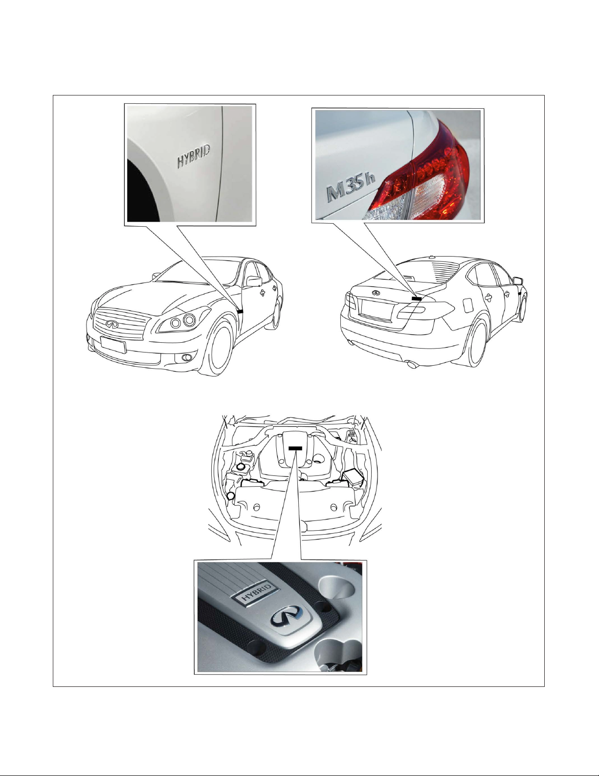
1-1 M35h HYBRID IDENTIFICATION
1-1.1 Exterior and Engine Compartment
AAYIA0003ZZ
6
Page 7
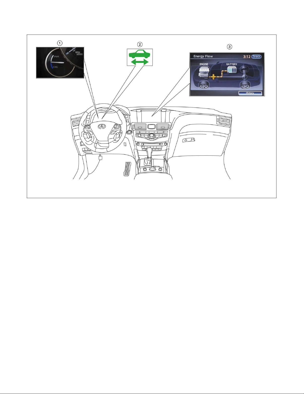
1-1.2 Interior
1. Assist charge gauge 2. READY indicator (green) 3. Energy flow display *1
*1: This screen may not be displayed due to customer settings.
AAYIA0081ZZ
7
Page 8
1-2 Vehicle Identification Number (VIN) Layout
In exterior appearance the M35h HYBRID is nearly identical to the conventional INFINITI M series vehicles.
The vehicle identification number can be located as follows:
Example VIN : JN1EY1APXCM005523
The M35h HYBRID is identified by the 4th alphanumeric character: E
E = M35h HYBRID
AAYIA0005ZZ
1. VIN plate (visible through windshield) 2. Vehicle certification plate (lower center pillar)
8
Page 9
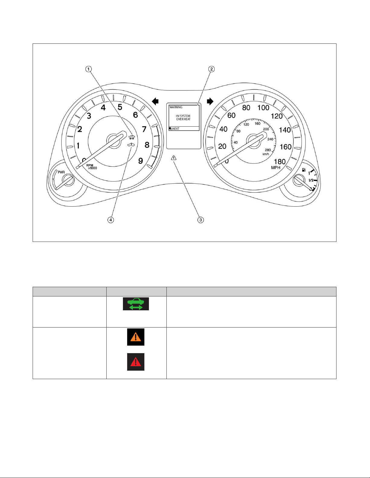
1-3 Warning and Indicator Lamp Information
AAYIA0010GB
1. READY Indicator (Green) 2. HV System Overheat Warning (Dot Matrix Liquid
Crystal Display)
3. Master Warning Lamp (Orange or Red) 4. Hybrid System Warning Lamp (Orange)
Lamp Name Icon Description
READY Indicator
(Green)
Master Warning Lamp
(Orange or Red)
This lamp is on when the high voltage system is powered
up and the vehicle is ready to drive.
This lamp is on when another warning lamp or message is
displayed in the instrument cluster.
9
Page 10

Lamp Name Icon Description
Hybrid System Warning
Lamp *1
(Orange)
This lamp is on or blinking when:
• Malfunction has occurred in the high voltage system
and/or
• High voltage leak to vehicle chassis and/or
• Emergency shut-off system has been activated. The
shut-off system activates in the following conditions:
– Front and side collisions in which the air bags are
deployed.
– Certain rear collisions.
– Certain high voltage system malfunctions.
*1: When this lamp is ON, the READY Indicator will turn OFF.
10
Page 11
2. Basic High Voltage Information
2-1 Battery Information
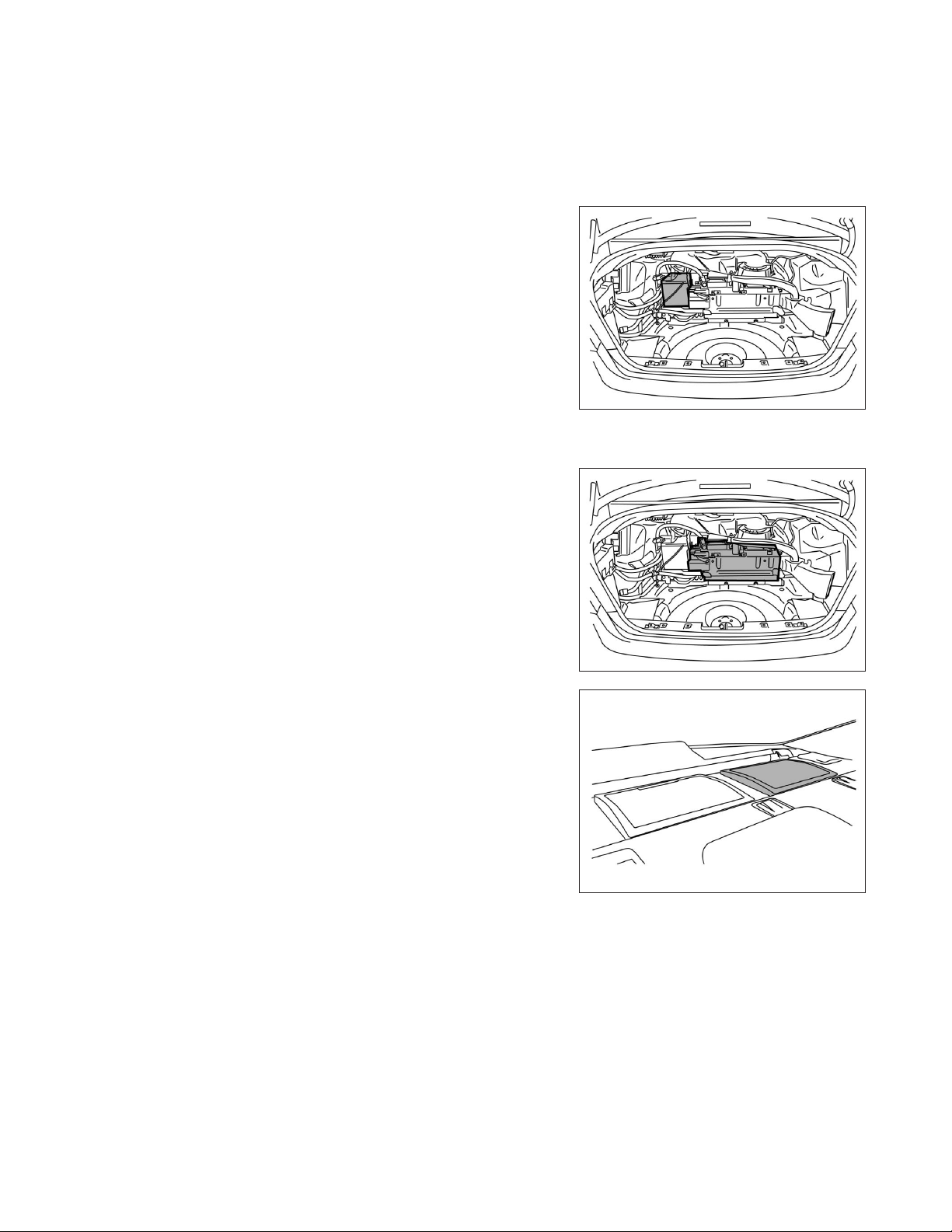
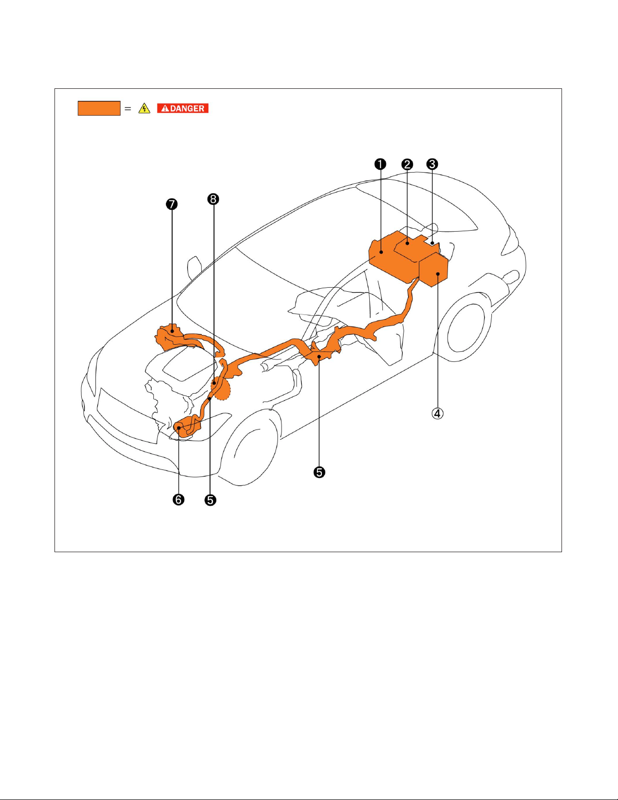
The M35h HYBRID utilizes two batteries in order to supply both high and low voltage.
2-1.1 12V Battery
• The M35h HYBRID contains a conventional lead-acid 12V
battery.
• The 12V battery is located in the trunk, left of Li-ion battery,
concealed by trim cover.
• The 12V battery is charged by the Li-ion battery through
the DC/DC converter.
2-1.2 Li-ion Battery
• The M35h HYBRID contains a Li-ion high voltage battery.
• The high voltage battery is mounted in the trunk area
behind the rear seat, enclosed in a metal case and
concealed by trim cover.
• The high voltage battery stores approximately 346 volts DC
(400V max.).
• The high voltage battery exhausts gases directly outside
the vehicle through a vent hose.
AAYIA0064ZZ
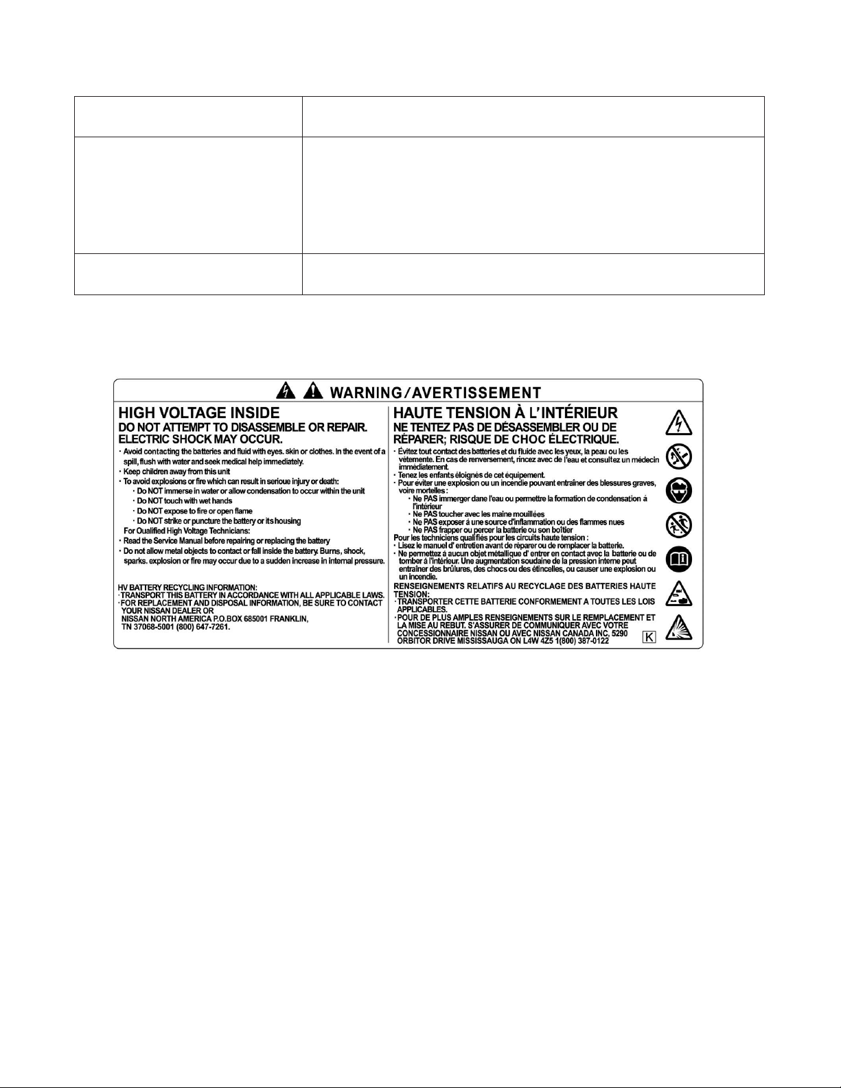
• An air vent is located on the rear parcel shelf for battery
cooling.
The high voltage battery supplies power to the following:
• High voltage harnesses
• DC/DC converter
• Traction motor inverter
• Traction motor
• Electric air conditioner compressor
AAYIA0065ZZ
AAYIA0066ZZ
11
Page 12
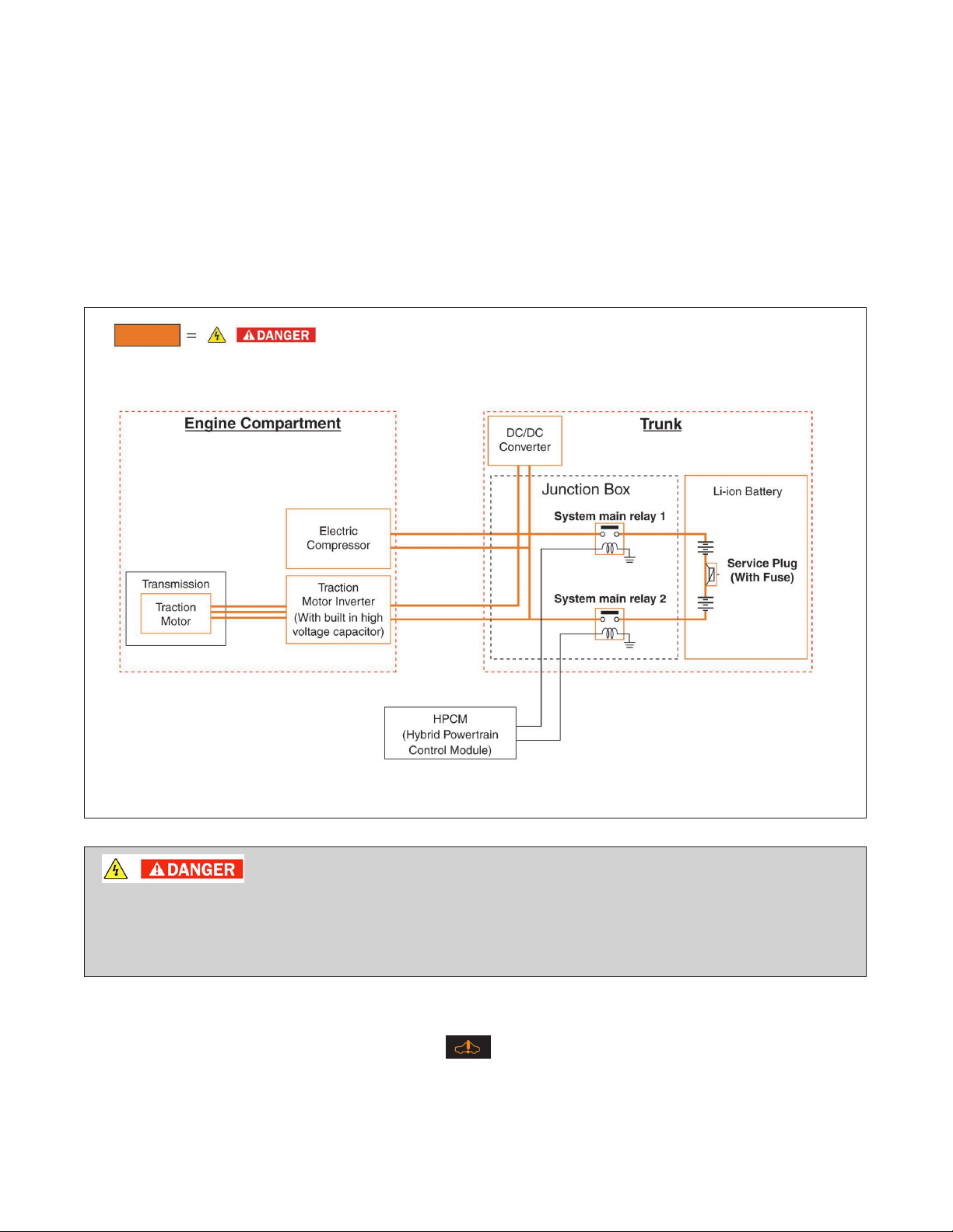
2-2 High Voltage-Related and 12V-Related Component Locations and
Descriptions
NOTE:
Components with white number in black background are high voltage components.
12
AAYIA0006ZZ
Page 13

No. Component Location Description
a Lithium-ion (Li-ion)
Battery
b DC/DC Converter Trunk area (mounted
c Service Plug Trunk area (below
d 12V Battery Trunk area (below
e High Voltage Har-
nesses
f Electric Air Condi-
tioner Compressor
g Traction Motor
Inverter
h Traction Motor Built-into the trans-
Trunk area (behind
rear seat back)
to top of Li-ion battery)
parcel shelf; behind
access door in trim
panel)
parcel shelf; behind
trim panel left of
Li-ion battery)
Trunk area (on Li-ion
battery), under floor
pan, engine compartment
Engine compartment (front driver
side)
Engine compartment (rear passenger side)
mission
The Li-ion battery stores and outputs DC
power (Maximum voltage 400V) needed to
propel the vehicle.
The DC/DC converter reduces the voltage of
the Li-ion battery to provide power to the 12V
battery in order to operate the vehicle’s electric
components (headlights, audio system, etc.).
This is used to disable the high voltage system.
A lead-acid battery that supplies power to the
low voltage devices.
Orange-colored power cables carry high DC
voltage between each of the high voltage components.
Air conditioner compressor
Converts the DC power stored in the Li-ion
battery to three-phase AC power and controls
motor torque (revolution) by regulating the
motor current. The inverter has a built in high
voltage capacitor.
Converts three-phase alternating current (AC)
power to drive power (torque) which propels
the vehicle.
2-3 Li-ion Battery Pack Specifications
Li-ion Battery Specifications
Li-ion battery voltage 346V (400V max.)
Number of Li-ion battery modules in the pack 12
Li-ion battery module voltage 28.8V each
Li-ion battery dimensions 33.35 x 17.83 x 15.43 in. (847 x 453 x 392 mm)
Li-ion battery weight 121.28 lbs (55 kg)
13
Page 14
2-4 High Voltage Safety Measures
Circuit insulation The high voltage positive (+) and negative (-) circuits are insulated
from the metal chassis.
Reducing the risk of electrocution The high voltage components and harnesses have insulated cases or
orange-colored coverings which provide insulation and easy identification.
The high voltage battery case is electrically connected to the vehicle
ground. This connection helps protect the vehicle occupants and
vehicle dismantlers
Identification The high voltage components are labeled “WARNING” similar to label
shown below. All high voltage harnesses are coated in orange.
2-4.1 Warning Label
from high voltage electrical shock.
14
AAYIA0010ZZ
Page 15
2-5 High Voltage Safety System
The high voltage safety system is intended to help keep vehicle occupants and emergency responders safe
from high voltage electricity.
• A high voltage fuse provides short circuit protection inside the high voltage battery.
• The high voltage safety system is insulated from the metal chassis.
• Positive and negative high voltage power cables are connected to the high voltage battery and are
controlled by normally open system main relays (SMR1 and SMR2). When the vehicle is shut off,
the relays stop electrical flow from leaving the high voltage battery. However, it can take up to
ten (10) minutes for the high voltage capacitor to fully discharge.
AAYIA0001GB
• The high voltage system and high voltage capacitor may remain powered for up to 10
minutes after the vehicle is shut off.
• The high voltage battery retains high voltage at all times.
• A ground fault monitor continuously monitors for high voltage leakage to the metal chassis while the
vehicle is running. If a malfunction is detected, the HPCM (hybrid powertrain control module) will
illuminate the hybrid system warning lamp
in the instrument cluster.
• The high voltage battery relays (SMR1 and SMR2) will automatically open to stop the electrical flow
in a frontal collision that is sufficient enough to activate the supplemental restraint system (SRS).
15
Page 16

2-6 High Voltage Circuit Shut-Off System
This vehicle is equipped with a system to shut off the current from the Li-ion battery by the following
methods:
Service plug Positioned in the center area of the Li-ion battery, this plug shuts off the out-
put of high voltage when manually removed.
System main relays Controlled by the ignition switch, these relays are powered by the 12V sys-
tem and shut off high voltage from the Li-ion battery.
Emergency shut-off system
In the case of a collision (air bag deployment, etc.) or certain system malfunctions this system shuts off the high voltage from the Li-ion battery.
2-7 Preventing Electrical Shock
1. If it is necessary to touch any of the high voltage harnesses or components, always wear
appropriate PPE (refer to
3-3.1 High Voltage System Shut-Down Procedure.
2.
To avoid the risk of electrocution, do not touch the inside of the Li-ion battery with bare hands
after shutting off the high voltage system. The Li-ion battery maintains charge even though the
high voltage system is shut down.
3. Cover damaged high voltage components with insulated tape.
3-1 Preparation Items). Shut off the high voltage system by referring to
16
Page 17

3. Preparation for Dismantling
• Failure to properly shut down the high voltage electrical system before the
Dismantling Procedures are performed will result in serious injury or death from
electrical shock. To prevent serious injury or death, DO NOT touch high voltage
harnesses or components without always wearing appropriate PPE.
• If it is necessary to touch any of the high voltage harnesses or components you must
always wear appropriate PPE to avoid electrical shock. Shut down the high voltage
system by following the steps outlined in
dure. Wait at least ten (10) minutes for complete discharge of the high voltage capacitor
after the high voltage system has been shut down.
• NEVER assume the M35h HYBRID is shut OFF simply because it is quiet.
• If it becomes necessary for the dismantler to leave the vehicle, place a “DANGER” sign
(for example, refer to 5. Storing the Vehicle) on the vehicle to alert other people that the
vehicle contains a high voltage battery.
• If the READY
• If possible, be sure to check the READY indicator on the instrument cluster and
verify that the READY indicator is OFF and the high voltage system is stopped.
indicator is ON the high voltage system is active.
3-3.1 High Voltage System Shut-Down Proce-
17
Page 18

3-1 Preparation Items
Preparation Items Specification Purpose
PPE (personal protective
equipment):
Insulated gloves
Insulated shoes
Safety shield
Up to 1,000V
–
–
For protection from high voltage electrical shock
Wrenches
Size:10mm
Solvent resistant protection gloves
Solvent resistant
protection shoes
Absorbent pad The same pad used for internal com-
bustion engine fluids can be used.
Standard fire fighting
equipment
Insulated tape Insulating
Standard fire fighting equipment.
Depending on type of fire (vehicle or
battery) use standard fire fighting
equipment (water or extinguisher).
–
–
3-2 Discharge Procedures
To remove the 12V battery terminal
bolt.
To utilize in the event of a Li-ion battery
electrolytic solution leak.
To absorb any Li-ion battery electrolytic
solution leakage.
To extinguish a fire.
To cover any damaged harnesses to
protect from and prevent electrical
shock. Tape should cover all bare or
damaged wire.
Failure to properly discharge the Li-ion battery before the dismantling procedures are
performed will result in serious injury or death from electrical shock.
Li-ion battery discharging must take place before dismantling. Sufficient discharging can be achieved by
following these steps.
1. Place the shift selector into the Park (P) position
2. Apply the parking brake.
3. Set wheel chocks to ensure the vehicle is completely stopped.
18
Page 19

4. Apply foot brake and press the ignition switch to turn the system ON. Confirm READY
indicator in instrument cluster turns ON.
a. If the engine starts, leave the engine on until idling stops.
b. If the engine does NOT start, move on to next step.
5. Remove the shift lock cover (A) using a suitable tool.
6. Push down the shift lock (B) as shown in the illustration.
7. Push the shift selector button (C) and move the shift
selector to Neutral (N) position (D) while holding down
the shift lock.
NOTE:
DO NOT press accelerator or foot brake after
moving the shift selector to the Neutral (N)
position. Otherwise Li-ion battery will start to be
AAYIA0067ZZ
charged.
8. Release the parking brake.
9. Turn ON electric devices such as headlamps, A/C (set to the coldest temperature) and rear
window defogger to discharge the high voltage battery. Allow approximately 15 minutes to
discharge. Discharge is complete when the READY
indicator (B) (green) turns OFF and
the hybrid system warning indicator (C) (orange) turns ON.
10. Press the ignition switch (A) to turn the system OFF.
Please contact following number if the vehicle could not be discharged.
• 1-800-662-6200 (US) or 1-800-361-4792 (Canada)
• Hours of operation are 8am-5pm (Monday-Friday) Eastern, Central and Pacific time zones.
AAYIA0033ZZ
19
Page 20

3-3 How to Handle a Damaged Vehicle
3-3.1 High Voltage System Shut-Down Procedure
Any of the following procedures can shut down the high voltage system. The dismantling operation can only
begin after shutting down the high voltage system. If the vehicle is heavily damaged, for example the Li-ion
battery is deformed, broken or cracked, appropriate PPE must always be used and the Li-ion battery and
high voltage components must not be touched.
• Failure to properly shut down the high voltage system before the dismantling
procedures are performed will result in serious injury or death from electrical shock.
To prevent serious injury or death, DO NOT touch high voltage harnesses or
components without always wearing appropriate PPE.
• When contact with high voltage components or high voltage harnesses is
unavoidable, or when there is risk of such contact, you must always wear appropriate
PPE.
20
Page 21

• The vehicle contains parts that contain powerful magnets. If a person who is wearing
a pacemaker or other medical device is close to these parts, the medical device may be
affected by the magnets. Such persons must not perform work on the vehicle.
• Be sure to check the READY indicator (1) in the instrument cluster, and verify that the
READY indicator is off and the high voltage system is stopped.
• After the high voltage system is shut down, please wait for ten (10) minutes for complete
discharge of the high voltage capacitor. While waiting, do not operate any vehicle
functions.
NOTE:
The high voltage full discharge takes ten (10) minutes, but after five (5) minutes the voltage
has dropped below 60V.
• Remove the 12V battery negative (-) terminal and wait for three (3) minutes to discharge
the air bag capacitor. Even though the 12V battery negative (-) is disconnected, the
Supplemental Restraint System (SRS) air bag maintains voltage for three (3) minutes.
There is a possibility of sudden SRS air bag inflation due to harness short circuit or
damage and it may cause serious injuries.
• The 12V system will remain active even after the 12V battery negative (-) terminal is
removed while the high voltage system is active. This is because the DC/DC converter will
not shut down and power will be supplied to the 12V system and high voltage system
continuously.
Before disconnecting the 12V battery terminal, if necessary, lower the windows, adjust the steering column,
adjust the seats, unlock the doors, open the trunk, etc. as required. Once the 12V battery is disconnected,
power controls will not operate.
Powering Down the High Voltage System
The high voltage system can be shut down with any 1 of the following procedures:
• Turn OFF the power switch and disconnect the 12V battery. Refer to
• Remove the fuse for the high voltage control system and disconnect the 12V battery. Refer to Alter-
nate Procedure 1.
• Remove the service plug and disconnect the 12V battery. Refer to Alternate Procedure 2.
Primary Procedure.
21
Page 22

Primary Procedure
NOTE:
Before disconnecting the 12V battery terminal, if necessary, lower the windows, adjust the
steering column, adjust the seats, unlock the doors, etc. Once 12V battery is disconnected,
power controls will not operate.
1. Check the READY indicator (A) status in the instrument cluster. If it is on, the high voltage system
is active.
AAYIA0062ZZ
2. Place the shift selector in the Park (P) position.
3. Push the ignition switch (B) once to turn OFF the high voltage system. Then verify whether the
READY indicator (A) is off.
If the READY indicator (A) does not turn off, continue to the next steps to open the trunk for 12V
battery negative cable access.
4. If possible, keep the INFINITI Intelligent Key™ at least 5
meters (16 feet) away from the vehicle (except as noted
below).
AAYIA0068ZZ
22
Page 23

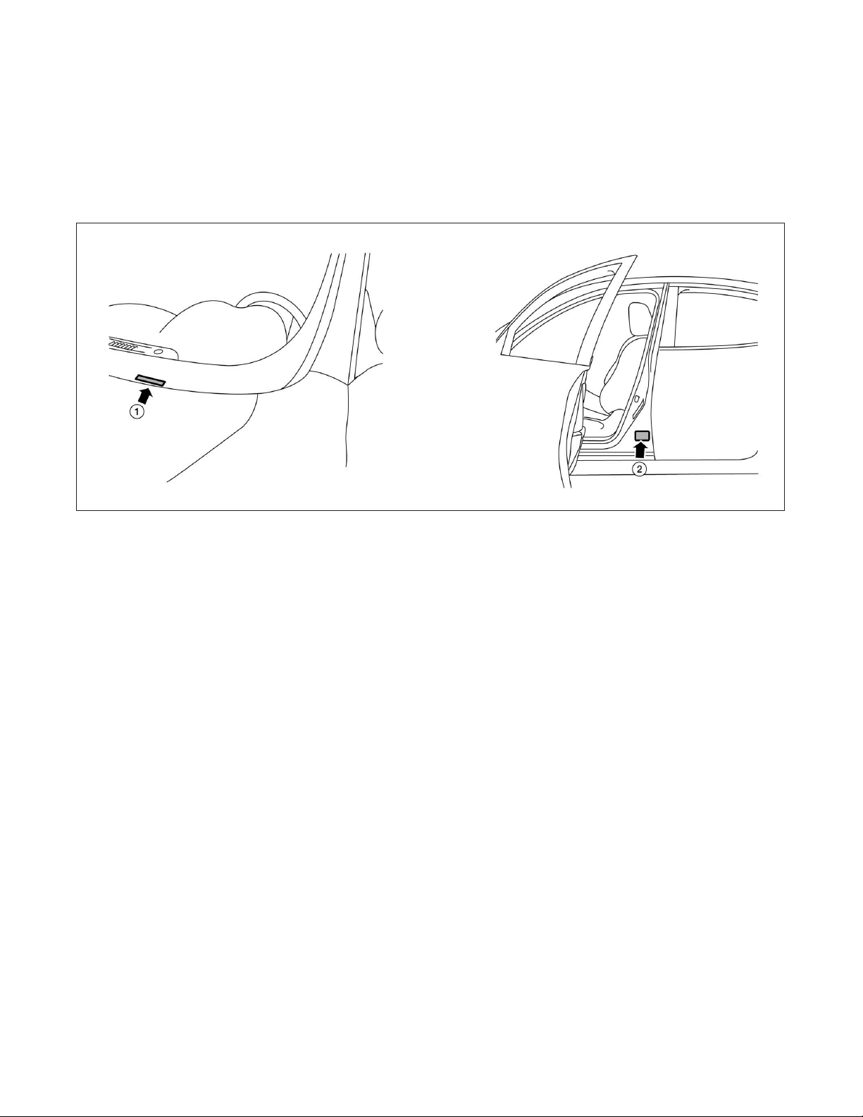
5. Open the trunk using any of the following:
a. push-button switch (C) on the lower LH side of the instrument panel.
b. trunk button (D) on the INFINITI Intelligent Key™ [press for longer than one (1) second].
c. trunk open request switch (E) (located above license plate)*.
d. with the mechanical key (F) housed inside the INFINITI Intelligent Key™.
Method Shift Selector Position Ignition Switch Status
a P or N Any
b P OFF
c* Any Any
d Any Any
* You must have the INFINITI Intelligent Key™ within approximately 1 meter (3 feet) range of trunk request
switch to use the trunk open request switch function.
23
Page 24

24
AAYIA0034ZZ
6. Open the 12V battery service access cover (G).
7. Disconnect negative (-) battery cable (H) and cover it with insulated tape.
8. Wait ten (10) minutes for complete discharge of the high voltage capacitor after the battery cable
has been disconnected.
9. Perform the dismantling operation. Refer to 6. Dismantling Information.
Page 25

Alternate Procedure 1
NOTE:
Before removing any fuses, if necessary, lower the windows, adjust the steering column,
adjust the seats, unlock the doors, etc. Once fuses are removed, power controls will not
operate.
1. Pull release handle (A) to open the hood.
2. Remove fuse box cover (B).
3. Remove 80A fuse (C) (black).
4. If you cannot identify the fuse (C), remove all fuses in the fuse box.
AAYIA0004GB
25
Page 26

AAYIA0011GB
5. Open the trunk. The trunk can be opened with the push-button switch (D) on the lower LH side of
the instrument panel or with the mechanical key (E) housed inside the INFINITI Intelligent Key™.
6. Open the 12V battery service access cover (F).
7. Disconnect negative (-) battery cable (G) and cover it with insulated tape.
8. Wait ten (10) minutes for complete discharge of the high voltage capacitor after the fuse is pulled
and battery cable has been disconnected.
9. Perform the dismantling operation. Refer to 6. Dismantling Information.
26
Page 27

Alternate Procedure 2
• Do not remove the service plug without always wearing appropriate PPE to help
protect the dismantler from serious injury or death by electrical shock.
• Immediately cover the service plug socket with insulated tape. To avoid electric shock,
DO NOT touch the terminals inside the socket.
To avoid unintended reinstallation and risk of electrical shock and severe personal injury
or death, the dismantler should carry the service plug on his/her person while work is
in progress.
NOTE:
Before disconnecting the 12V battery terminal, if necessary, lower the windows, adjust the
steering column, adjust the seats, unlock the doors, etc. Once 12V battery is disconnected,
power controls will not operate.
1. Check the READY indicator (A) status in the instrument cluster. If it is on, the high voltage system
is active.
AAYIA0062ZZ
2. Place the shift selector in the Park (P) position.
3. Push the ignition switch (B) once to turn OFF the high voltage system. Then verify whether the
READY indicator (A) is off.
If the READY indicator (A) does not turn off, continue to the next steps to open the trunk for 12V
battery negative cable access.
27
Page 28

4. If possible, keep the INFINITI Intelligent Key™ at least 5
meters (16 feet) away from the vehicle (except as noted
below).
5. Open the trunk using any of the following:
a. push-button switch (C) on the lower LH side of the instrument panel.
b. trunk button (D) on the INFINITI Intelligent Key™ [press for longer than one (1) second].
c. trunk open request switch (E) (located above license plate)*.
d. with the mechanical key (F) housed inside the INFINITI Intelligent Key™.
Method Shift Selector Position Ignition Switch Status
a P or N Any
b P OFF
c* Any Any
d Any Any
AAYIA0068ZZ
* You must have the INFINITI Intelligent Key™ within approximately 1 meter (3 feet) range of trunk request
switch to use the trunk open request switch function.
28
Page 29

AAYIA0035ZZ
6. Open the 12V battery service access cover (G).
7. Disconnect negative (-) battery cable (H) and cover it with insulated tape.
8. Open service plug access cover (J).
9. Remove the service plug (K) by pressing the locking tab (L) and rotating the handle (M) fully
outward (N). Using the handle, pull the service plug (P) completely out of its socket.
10. Cover the service plug socket with insulated tape.
29
Page 30

11. Wait ten (10) minutes for complete discharge of the high voltage capacitor after the service plug
has been removed.
12. Perform the dismantling operation. Refer to 6. Dismantling Information.
3-3.2 Cutting the Vehicle Body
• Do not cut into high voltage related areas to avoid severe personal injury or death.
•
Do not cut into the Li-ion battery to avoid severe personal injury or death.
• When removing parts, DO NOT touch the high voltage parts or the insides of the
exposed orange-colored high voltage cables to avoid severe personal injury or death.
Do not cut air bag parts to avoid unintended deployment of the air bags and the risk of
severe personal injury or death.
If ten (10) minutes have passed since the rescuer shut down the high voltage system (refer to 3-3.1 High
Voltage System Shut-Down Procedure), then the dismantler can cut the vehicle except for the Li-ion battery.
DO NOT cut the Li-ion battery due to possible electrocution risk and electrolyte solution
leakage.
30
Page 31

SRS Air Bag System Components Location
The SRS air bag system must not be cut as there is a risk of short circuit and unintentional deployment of
the SRS However, the vehicle can be cut (except inflators) under the following conditions:
• The front, side and curtain air bags have deployed.
• At least three (3) minutes have passed after the 12V battery negative (-) cable has been
disconnected and the high voltage system has been shut down.
1. Crash zone sensor 2. Supplemental front air bag
modules (INFINITI Advanced Air
3. Front seat-mounted sideimpact supplemental air bags
Bags)
4. Occupant classification sensor
(pattern sensor)
7. Roof-mounted curtain side-
impact supplemental air bags
5. Occupant classification system
control unit
8. Roof-mounted curtain sideimpact supplemental air bag infla-
6. RH seat belt with pretensioner
9. RH satellite sensor
tors
10. Air bag control unit (ACU) 11. LH seat belt with pretensioner 12. LH Satellite sensor
13. Lap outer pretensioner (if so
equipped)
14. Front door satellite sensor LH
(RH similar)
AAYIA0020ZZ
31
Page 32

32
Vehicle Cut Sheet
AAYIA0005GB
Page 33

3-3.3 Water Submersion
Damage level of submerged vehicle may not be apparent. Handling a submerged vehicle
without appropriate PPE will result in serious injury or death from electrical shock.
• The ignition switch of the submerged vehicle must be turned OFF first, if possible.
Then the vehicle must be completely out of the water and drained to avoid electrical
shock.
• Always wear appropriate PPE and remove/drain water before removing the service
plug when working on a vehicle after a fire or submersion to avoid electrical shock.
• If the vehicle is in the water, to avoid electrical shock do not touch the high voltage
components, harnesses or service plug.
3-3.4 Vehicle Fire
• Always utilize full PPE and self-contained breathing apparatus during fire fighting
operations. Smoke from a M35h HYBRID vehicle fire is similar to smoke from a
conventional vehicle fire.
• In the case of extinguishing a fire with water, large amounts of water from a fire hydrant
(if possible) must be used. DO NOT extinguish fire with a small amount of water.
In the event of a small fire, a Type ABC fire extinguisher may be used for an electrical fire
caused by wiring harnesses, electrical components, etc. or oil fire.
In case of vehicle fire, contact fire department immediately and extinguish the fire if possible. If you must
walk away from the vehicle, notify an appropriate responder or a rescue person of the fact that the vehicle is
a hybrid vehicle that contains a high voltage system and warn all others.
33
Page 34

3-3.5 Li-ion Battery Damage and Fluid Leaks
In cases of battery case breach or electrolyte leakage, contact the fire department immediately. If you must
walk away from the vehicle, notify an appropriate responder of the fact that the vehicle is an electric car and
contains a high voltage system and warn all others.
Li-ion Battery Electrolyte Solution Characteristics:
• Clear in color
• Sweet odor
• Similar viscosity to water
• Skin irritant
• Eye irritant – If contact with eyes, rinse with plenty of water and see a doctor immediately.
• If electrolyte leak occurs, wear appropriate solvent resistant PPE and use a dry cloth to clean up the
spilled electrolyte. Be sure to adequately ventilate the area.
• Highly flammable
• Electrolyte liquid or fumes that have come into contact with water vapors in the air will create an
oxidized substance. This substance may irritate skin and eyes. In these cases, rinse with plenty of
water and see a doctor immediately.
• Electrolyte fumes (when inhaled) can cause respiratory irritation and acute intoxication. Move to
fresh air and wash mouth with water. See a doctor immediately.
• Since the Li-ion battery is made up of many small sealed battery modules, electrolyte solution
leakage should be minimal.
34
Page 35

4. Jump Starting
To start the hybrid system with a booster battery, the instructions and precautions below must be followed.
If done incorrectly, jump starting can lead to a 12V battery explosion, resulting in severe
personal injury or death. It could also damage your vehicle.
Jump starting provides power to the 12V system to allow the electrical systems to operate. The electrical
systems must be operating to allow the Li-ion battery to be charged. Jump starting does not charge the
Li-ion battery.
Discharged 12V battery may cause the following issues:
• The instrument cluster cannot be displayed while the ignition switch is turned ON. (The hybrid
system cannot start.)
• Headlamps, horn, etc. are weak.
• To avoid electrical shock, the high voltage Li-ion battery CANNOT be jump started.
• Explosive hydrogen gas is always present in the vicinity of the 12V battery. Keep all
sparks and flames away from the 12V battery.
• Do not allow battery fluid to come into contact with eyes, skin, clothing or painted
surfaces. Battery fluid is a corrosive sulfuric acid solution that can cause severe burns. If
the fluid comes into contact with anything, immediately flush the contacted area with
water.
• The booster battery must be rated at 12 volts. Use of an improperly rated battery can
damage the vehicle.
• Whenever working on or near a 12V battery, always wear suitable eye protectors (for
example, goggles or industrial safety spectacles) and remove rings, metal bands, or any
other jewelry. Do not lean over the 12V battery when jump starting.
• Do not attempt to jump start a frozen battery. It could explode and cause serious injury.
• M35h HYBRID is equipped with an automatic cooling fan. It could come on at any time.
Keep hands and other objects away from it.
• Always follow the jump starting instructions below. Failure to do so could result in
damage to the DC/DC converter and cause personal injury.
35
Page 36

4-1 Jump Starting Procedures
NOTE:
AAYIA0069ZZ
Jumper cable connections under the hood of the M35h HYBRID are not connected directly
to a battery. They are connected to chassis ground and a fuse box terminal. Refer to the
following instructions and the above illustration.
1. If the booster battery is in another vehicle (A), position the two vehicles (A and B) to bring the
12V battery and fuse box into close proximity to each other.
DO NOT allow the two vehicles to touch.
2. Apply the parking brake. Move the selector lever the P (Park) position. Switch off all unnecessary
electrical systems (headlights, heater, air conditioner, etc.).
3. Remove fuse box cover on the M35h HYBRID and connect jumper cables in the sequence as
illustrated (a→b→c→d).
For models with a steering wheel lock mechanism:
If the 12V battery is disconnected or discharged, the steering wheel will lock and cannot be
turned. Supply power using jumper cables before pushing the ignition switch and disengaging
the steering lock.
• Always connect positive (+) to positive (+) and negative (-) to body ground (for example,
as illustrated), not to the 12V battery.
• Make sure the jumper cables do not touch moving parts in the engine compartment and
that the cable clamps do not contact any other metal.
• If the hybrid system does not start right away, push the ignition switch to the OFF
position and wait ten (10) seconds before trying again.
36
4. Start the engine of the booster vehicle (A) and let it run for a few minutes.
5. Start the hybrid system of the vehicle being jump started (B).
Page 37

6. After starting the hybrid system, carefully disconnect the negative cable and then the positive
cable (d→c→b→a).
7. Reinstall the fuse box cover.
NOTE:
If it is not possible to turn the hybrid system ON by following this procedure, contact
an INFINITI retailer immediately.
4-2 Shift Selector Lever Lock Release
If the 12V battery is low or discharged, the selector lever cannot be moved from the Park (P) position. If a booster battery is not available, the selector lever lock can be manually released. To manually release the selector lever lock, perform
the following procedure:
1. Push the ignition switch to the LOCK or OFF position.
2. Apply the parking brake.
3. Remove the shift lock cover (A) using a suitable tool.
4. Push down the shift lock (B) as shown in the illustration.
5. Push the selector lever button (C) and move the selector
lever to the Neutral (N) position (D) while holding down
the shift lock.
AAYIA0067ZZ
37
Page 38

5. Storing the Vehicle
If the M35h HYBRID needs to be stored or left unattended, the high voltage system must be shut down by
removing the service plug (refer to
hybrid vehicle with high voltage dangers. For example:
Alternate Procedure 2) and a sign put on the vehicle indicating it is a
38
AAYIA0020GB
Page 39

6. Dismantling Information
Removal or repair of the high voltage battery requires special tools and specific training. INFINITI strongly
recommends that only certified INFINITI retailer technicians perform these operations.
6-1 Precautions for Handling High Voltage Lithium-ion (Li-ion) Battery
• Because M35h HYBRID contains a high voltage (Li-ion) battery, there is the risk of
electric shock, electric leakage, or similar accidents if the high voltage components or
vehicle is handled incorrectly. Be sure to follow the correct work procedures when
performing inspection and dismantling.
• The colors of the high voltage harnesses and connectors are all orange. Orange (High
Voltage( labels are applied to the Li-ion battery and other high voltage devices. Do not
touch the Li-ion battery or other high voltage devices without always wearing appropriate
PPE.
• Clearly identify the persons responsible for high voltage work and ensure that other
persons do not touch the vehicle. When not working, cover high voltage parts with an
insulating cover sheet and sign or similar item to prevent other persons from contacting
them.
•
The high voltage battery retains high voltage at all times.
• Be sure to always wear appropriate PPE before beginning work on the high voltage
system.
• If it is necessary to touch any of the high voltage harnesses or components you must
always wear appropriate PPE and properly shut-down the high voltage system by
removing the service plug.
•
Be sure to remove the service plug in order to shut-down the high voltage system
before performing inspection or dismantling of high voltage system harnesses and parts.
• Be sure to put the removed service plug in your pocket and carry it with you so
another person does not accidentally reinstall it while work is in progress.
•
Immediately insulate disconnected high voltage connectors and terminals with
insulated tape.
• The vehicle contains parts that contain powerful magnets. If a person who is wearing
a pacemaker or other medical device is close to these parts, the medical device may be
affected by the magnets. Such persons must not perform work on the vehicle.
•
Because this vehicle uses components that contain high voltage and powerful
magnetism, do not carry any metal products which may cause short circuits, or any
magnetic media (cash cards, credit cards, etc.) which may be damaged when working on
the vehicle.
• Keep removed Li-ion battery packs away from rain to avoid electric shock.
•
If the vehicle is heavily damaged, for example the Li-ion battery is deformed, broken,
or cracked; appropriate PPE must always be used at all times to avoid electrical shock.
• Do not heat removed battery packs higher than 158° F (70° C).
39
Page 40

There is the possibility of a hybrid system malfunction occurring if the vehicle is changed to
READY
status while the service plug is removed.
6-2 PPE (Personal Protective Equipment) and Insulated Tools
6-2.1 PPE (Personal Protective Equipment) Protective Wear Control
Perform an inspection of the PPE items before beginning work. Do not use any damaged PPE items.
6-2.2 Daily Inspection
This inspection is performed before and after use. The worker who will be using the items should perform
the inspection and check for deterioration and damage.
• Insulated rubber gloves should be inspected for scratches, holes and tears. (Visual check and air
leakage test)
• Insulated safety boots should be inspected for holes, damage, nails, metal pieces, wear or other
problems on the soles. (Visual check)
• Insulated rubber sheet should be inspected for tears. (Visual check)
6-2.3 Insulated Tools
When performing work at locations where high voltage is applied (such as terminals), use insulated tools
meeting 1,000V/300A specifications.
40
Page 41

6-3 Lithium-ion (Li-ion) Battery Pack Removal
6-3.1 Exploded View
AAYIA0036ZZ
1. Battery inlet duct A 2. Li-ion battery assembly 3. DC/DC converter outlet duct
4. Battery outlet duct B 5. Battery outlet duct A 6. Battery inlet duct B
7. Battery cooling fan 8. DC/DC converter inlet duct
6-3.2 Removal Procedure
1. Remove the service plug. Refer to
2.
Insert an appropriate tool into the gap between the trunk lamp case and front trunk trim panel to
Alternate Procedure 2.
remove the trunk lamp case.
3. Disconnect the trunk lamp harness connector.
4. Remove the trunk lid weather strip.
5. Remove the front trunk trim retainer clips.
41
Page 42

6. Remove the front trunk trim panel (1) and remove the trunk floor trim panel (2).
AAYIA0070ZZ
7. Remove the battery inlet duct A (1), DC/DC converter outlet duct (2) and battery outlet duct B
(3).
8. Remove the DC/DC harness (1), the 12V battery vent
tube (2) and the high voltage harness clip (A).
Grip the tip of the tube to remove the 12V battery vent
tube.
42
AAYIA0071ZZ
JSCIA0011ZZ
Page 43

9. Remove the mounting bolts (A) and then remove the 12V
battery cover (1).
10. Disconnect the fusible link connectors (2) that are
integrated with the 12V positive battery cable (1).
11. Remove 12V battery by removing the negative battery
cable (1), positive battery cable (2) and frame (3).
AAYIA0072ZZ
AAYIA0073ZZ
To prevent damage to the parts:
a) Disconnect the negative battery cable first
b) Immediately cover the battery cables with insulated
tape.
12. Remove the terminal cover bolts (A) and nut (B), then
remove the terminal cover (1).
Touching high voltage components without wearing
appropriate PPE will cause electrocution.
AAYIA0074ZZ
JSCIA0013ZZ
43
Page 44

13. Disconnect the high voltage harness connectors (A).
Touching high voltage components without wearing
appropriate PPE will cause electrocution.
• Touching high voltage components without
wearing appropriate PPE will cause
electrocution.
• Immediately cover the terminals of the
disconnected high voltage harness connectors
using insulated tape so that they are not
exposed.
• Immediately protect the terminals of the
disconnected battery junction box using
insulated tape so that they are not exposed.
14. Grasp the rubber base of the gas discharge tube (1) and
remove from the vehicle-side discharge port (body
member).
JSCIA0014ZZ
AAYIA0075ZZ
Touching high voltage components without wearing
appropriate PPE will cause electrocution.
15. Hook approximately 15mm (A) from the end of the gas
discharge tube (1) onto the tube base on the battery and
check that the flange on the end of the tube does not
come off from the tube base.
Touching high voltage components without wearing
appropriate PPE will cause electrocution.
JSCIA0015ZZ
JSCIA0016ZZ
44
Page 45

16. Remove the mounting nut (A) and then disconnect the
harness from the fuse box on the left side of the trunk
room.
17. Disconnect the brake power supply backup unit harness
connector (A) and remove the ground cable mounting
bolts (B).
: Vehicle front
18. Disconnect the high voltage harness connector (A) and
harness connector (B).
JSCIA0279ZZ
JSCIA0280ZZ
: Vehicle front
Touching high voltage components without wearing
appropriate PPE will cause electrocution.
Immediately protect the terminals of the disconnected
high voltage harness connector socket using
insulated tape so that they are not exposed.
JSCIA0281ZZ
AAYIA0043ZZ
45
Page 46

19. Disconnect the Li-ion battery cooling fan motor harness connector.
20. Release the two rear seat cushion retainers.
AAYIA0044ZZ
21. Lift up and pull out the rear seat cushion (1) and then remove the rear seat back nuts (3). Lift up
the rear seat back (2) and remove it.
46
AAYIA0045ZZ
Page 47

22. Remove the 4 clips ( ) and the HPCM cover (1).
AAYIA0076ZZ
23. Disconnect the HPCM harness connectors (1), and remove the HPCM mounting bolts, nuts and
then the HPCM (2).
24. Remove the high voltage battery pack mounting bolts (A)
from the passenger compartment side.
: Vehicle front
NOTE:
It is possible to access the mounting bolts (1)
when the noise insulation sheet that is attached
to the body panel behind the rear seat back is
removed.
Touching high voltage components without wearing
appropriate PPE will cause electrocution.
AAYIA0047ZZ
JSCIA0017ZZ
JSCIA0022ZZ
47
Page 48

25. Remove the high voltage battery pack mounting bolts (A)
from the trunk side.
: Vehicle front
Touching high voltage components without wearing
appropriate PPE will cause electrocution.
26. Place a plywood panel (A) on top of the spare tire, then
lift the high voltage battery pack upwards (1) and slide a
cardboard panel (B) underneath it (2).
Touching high voltage components without wearing
appropriate PPE will cause electrocution.
JSCIA0018ZZ
JSCIA0019ZZ
27. Pull the cardboard (A) together with the high voltage
battery pack (1) toward the rear of the vehicle.
Touching high voltage components without wearing
appropriate PPE will cause electrocution.
JSCIA0020ZZ
48
Page 49

28. Follow the procedure below to remove the high voltage battery pack from the trunk room.
Touching high voltage components without wearing appropriate PPE will cause
electrocution.
a. Attach carabiners (A) in the positions as shown in the figure, and then connect a slinger (B)
to them.
JSCIA0021ZZ
b. Using an engine crane (A) to lift up the high voltage battery pack (1) and remove it from the
trunk room.
JSCIA0284ZZ
49
Page 50

• Be careful that the engine crane does not contact
the trunk lid.
• Apply protection so that no scratches or other
damage occurs on the vehicle body or trunk lid.
29. Remove the DC/DC converter inlet duct clips (A) and
then the DC/DC converter inlet duct (1).
Touching high voltage components without wearing
appropriate PPE will cause electrocution.
30. Remove the battery cooling fan mounting bolts (A) and
remove the battery cooling fan (1).
JSCIA0282ZZ
AAYIA0048ZZ
Touching high voltage components without wearing
appropriate PPE will cause electrocution.
AAYIA0049ZZ
50
Page 51

31. Confirm that the insulated tape is still securely in place on the high voltage battery pack as shown
in the figure.
: Insulated tape
AAYIA0077ZZ
32. Dismantling the remainder of the M35h HYBRID may be performed like conventional INFINITI
vehicles once the high voltage system is properly shut down and discharged.
6-4 Li-ion Battery Recycling
The high voltage battery is recyclable. For information regarding recycling of the high voltage battery,
contact the nearest INFINITI retailer or INFINITI Consumer Affairs at: United States: 1-800-662-6200 or in
Canada: 1-800-361-4792.
51
Page 52

© 2012 NISSAN NORTH AMERICA, INC.
All rights reserved.
This document may not be altered without the written permission of NISSAN NORTH AMERICA, INC.
Pub. No. DG3E-1Y51U1
52
 Loading...