

Page 1

Edition: January 2005
Revision: January 2006
Publication No. SM6E-1Y50U2
QUICK REFERENCE INDEX
A
GENERAL INFORMATION
B ENGINE
C TRANSMISSION/
TRANSAXLE
D DRIVELINE/AXLE
E SUSPENSION
F BRAKES
G STEERING
H RESTRAINTS
I BODY
J AIR CONDITIONER
K ELECTRICAL
L MAINTENANCE
M INDEX
GI
General Information
EM
Engine Mechanical
LU
Engine Lubrication System
CO
Engine Cooling System
EC
Engine Control System
FL
Fuel System
EX
Exhaust System
ACC
Accelerator Control System
AT
Automatic Transmission
TF
Transfer
PR
Propeller Shaft
FFD
Front Final Drive
RFD
Rear Final Drive
FAX
Front Axle
RAX
Rear Axle
FSU
Front Suspension
RSU
Rear Suspension
WT
Road Wheels & Tires
BR
Brake System
PB
Parking Brake System
BRC
Brake Control System
PS
Power Steering System
STC
Steering Control System
SB
Seat Belts
SRS
Supplemental Restraint System
(SRS)
BL
Body, Lock & Security System
GW
Glasses, Window System & Mirrors
RF
Roof
EI
Exterior & Interior
IP
Instrument Panel
SE
Seat
ATC
Automatic Air Conditioner
SC
Starting & Charging System
LT
Lighting System
DI
Driver Information System
WW
Wiper, Washer & Horn
BCS
Body Control System
LAN
LAN System
AV
Audio-Visual System
ACS
Auto Cruise Control System
PG
Power Supply, Ground & Circuit Elements
MA
Maintenance
IDX
Alphabetical Index
A
B
C
D
E
F
G
H
I
J
K
L
M
All rights reserved. No part of this Service Manual may be reproduced or stored in a retrieval system, or
transmitted in any form, or by any me ans, ele ctronic , me cha nic al, rec ordin g or oth erwise, wit hout th e prior
written permission of Nissan Motor Company Ltd., Tokyo, Japan.
Page 2

This manual contains maintenance and repair procedure for the 2006
INFINITI M35/M45.
In order to assure your safety and the efficient functioning of the vehicle,
this manual should be read thoroughly. It is especially important that the
PRECAUTIONS in the GI section be completely understood before starting
any repair task.
All information in this manual is based on the latest product information
at the time of publication. The right is reserved to make changes in specifications and methods at any time without notice.
IMPORTANT SAFETY NOTICE
The proper performance of service is essential for both the safety of
the technician and the efficient functioning of the vehicle.
The service methods in this Service Manual are described in such a
manner that the service may be performed safely and accurately.
Service varies with the procedures used, the skills of the technician
and the tools and parts available. Accordingly, anyone using service
procedures, tools or parts which are not specifically recommended
by NISSAN must first be completely satisfied that neither personal
safety nor the vehicle’s safety will be jeopardized by the service
method selected.
Page 3

QUICK REFERENCE CHART M35/M45
2006
QUICK REFERENCE CHART M35/M45 PFP:00000
ENGINE TUNE-UP DATA (VQ35DE) ELS0003W
Engine model VQ35DE
Firing order 1-2-3-4-5-6
Idle speed
A/T (In “P” or “N” position)
Ignition timing (BTDC at idle speed)
A/T (In “P” or “N” position)
CO% at idle 0.7 - 9.9% and engine runs smoothly
Deflection adjustment Unit: mm (in) Tension adjustment Unit: N (kg, lb)
Drive Belt
Limit After adjustment Limit After adjustment
Alternator and power
steering oil pump belt
A/C compresor belt 12 (0.47)
Applied pushing force 98N (10kg, 22lb) —
Radiator cap relief pressure
Cooling system leakage testing pres sure
Compression pressure
Spark plug Standard type PLFR5A-11
7 (0.28)
Standard 78 - 98 (0.8 - 1.0, 11 - 14)
Limit 59 (0.6, 9)
Standard 1,275 (13.0, 185) /300
Minimum 981 (10.0, 142) /300
Hot type PLFR4A-11
Cold type PLFR6A-11
Used belt
4 - 5
(0.16 - 0. 20)
9 - 10
(0.35 - 0. 39)
kPa (kg/cm
kPa (kg/cm
kPa (kg/cm2 , psi)/rpm
2
, psi)
2
, psi)
rpm
New belt
3.5 - 4.5
(0.138 - 0. 177)
8 - 9
(0.31 - 0.35)
650 ± 50
294 (30, 66)
196 (20, 44)
157 (1.6, 23)
15° ± 5°
Used belt
730 - 818
(74.5 - 83.5,
164 - 184)
348 - 436
( 35.5 - 44.5,
78 - 98)
New belt
838 - 926
(85.5 - 94.5,
188 - 208)
470 - 559
(48 - 57,
106 - 126)
Page 4

QUICK REFERENCE CHART M35/M45
ENGINE TUNE-UP DATA (VK45DE)
Engine model VK45DE
Firing order 1-8-7-3-6-5-4-2
Idle speed
A/T (In “P” or “N” position) rpm
Ignition timing
(BTDC at idle speed)
CO% at idle 0.7 - 9.9% and engine runs smoothly
Tens io ns of drive belts Auto adjustment by auto tensioner
Radiator cap relief pressure
Limit 59 (0.6, 9)
Cooling system leakage testing pressure
kPa (kg/cm
Compression pressure
Minimum 1,130 (11.5, 164) /300
Spark plug Standard type PLFR5A-11
Hot type PLFR4A-11
Cold type PLFR6A-1 1
2
, psi)
kPa (kg/cm
kPa (kg/cm
2
, psi)
2
7 8 - 98 (0.8 - 1.0 , 11 - 14)Standard
, psi)/rpm
650 ± 50
12° ± 5°
157 (1.6, 23)
1,320 (13.5, 191) /300Standard
2006
FRONT WHEEL ALIGNMENT (Unl aden* )
Axle 2WD AWD
Tire P245/45R 18 245/40R19 245/45R18
Minimum – 1° 00′ (– 1.00°)
Camber
Degree minute (Decimal degree)
Caster
Degree minute (Decimal degree)
Kingpin inclination
Degree minute (Decimal degree)
Distance (A – B)
Total toe-in
Angle (left plus right)
Degree minute
(Degree)
Nominal – 0° 15′ (– 0.25°)
Maximum 0° 30′ (0.50°)
Left and right difference 33′ (0.55°) or less
Minimum 3° 45′ ( 3.75° )3° 50′ (3.83°)3° 05′ ( 3.08° )
Nominal 4° 30′ ( 4.50° )4° 35′ (4.58°)3° 50′ ( 3.83° )
Maximum 5° 15′ ( 5.25° )5° 20′ (5.33°)4° 35′ ( 4.58° )
Left and right difference 39′ (0.65°) or less
Minimum 6° 30′ (6.50°)
Nominal 7° 15′ (7.25°)
Maximum 8° 00′ (8.00°)
Minimum 0 mm (0 in)
Nominal 1 mm (0.04 in)
Maximum 2 mm (0.08 in)
Minimum 0′ (0°)
Nominal 3′ (0.05°)
Maximum 6′ (0.10°)
ELS0003X
Page 5

QUICK REFERENCE CHART M35/M45
Axle 2WD AWD
Tire P245/45R 18 245/40R19 245/45R18
Inside
Degree minute
Wheel turning
angle (Full turn)
* : Fuel, engine coolant and engine oil full. Spare tire, jack, hand tools and mats in designa te d posi tions.
(Decimal degree)
Outside
Degree minute
(Decimal degree)
Minimum 36°20′ (36.3°)39°45′ (39.8°)
Nominal 39°20′ (39.3°)42°45′ (42.8°)
Maximum 40°20′ (40.3°)43°45′ (43.8°)
Nominal 33° 25′ (33.4°)33° 20′ (33.3°)32° 30′ (32.5°)
2006
REAR WHEEL ALIGNMENT (Unladen*) ELS0003Y
Axle 2WD AWD
Tire P245/45R18 245/40R19 245/45R18
Minimum – 1° 10′ (– 1.17°)– 1° 20′ (– 1.33°)– 1° 40′ (– 0.67°)
Camber
Degree minute (Decimal degree)
Distance ( A – B )
Total toe-in
Angle (left plus right )
Degree minute
(Decimal degree)
* : Fuel, engine coolant and engine oil full. Spare tire, jack, hand tools and mats in designa te d posi tions.
Nominal – 0° 40′ (– 0.67°)– 0° 50′ (– 0.83°)– 0° 10′ (– 0.17°)
Maximum – 0° 10′ (– 0.17°)– 0° 20′ (– 0.33°) 0° 20′ (0.33° )
Minimum 0.1 mm (0.004 in)
Nominal 2.8 mm (0.110 in)
Maximum 5.5 mm (0.217 in)
Minimum 0′ (0°)
Nominal 7′ (0.12°)
Maximum 14′ (0.23°)
BRAKE ELS0003Z
Front brake Pad wear limit 2.0 mm (0.079 in)
Rotor repair limit 26.0 mm (1.024 in)
Rear brake Pad wear limit 2.0 mm (0.079 in)
Rotor repair limit 14.0 mm (0.551 in)
Pedal free height 157 - 167 mm (6.18 - 6.57 in)
Pedal depressed height* 90 mm (3.54 in) or more
* : Under force of 490 N ( 50 kg, 110 lb ) with engine running.
REFILL CAPACITIES ELS00040
UNIT Liter US measure
Fuel tank 76 20 gal
Coolant ( With reservoir tank )
Engine (VQ35DE)
Engine (VK45DE)
VQ35DE 8.9 9 - 3/8 qt
VK45DE 10.4 11 qt
Drain and refill
With oil filter change 4.7 5 qt
Without oil filter change 4.4 4 - 5/8 qt
Dry engine (Overhaul) 5.4 5 - 3/4 qt
Drain and refill
With oil filter change 5.5 5 - 3/4 qt
Without oil filter change 4.9 5 - 1/8 qt
Dry engine (Overhaul) 6.7 7 - 1/8 qt
Page 6

QUICK REFERENCE CHART M35/M45
UNIT Liter US measure
Transmission A/T 10.3 10 - 7/8 qt
Transfer 1.25 2 - 5/8 pt
Differential carrier
Power steering system 1.0 1 - 1/8 qt
Air conditioning system
Front 0.65 1 - 3/8 pt
Rear 1.4 3 pt
Compressor oil 0.15 5.03 fl oz
Refrigerant 0.55 kg 1.21 lb
2006
Page 7

GENERAL INFORMA TION
A GENERAL INFORMATION
GI
B
SECTION GI
CONTENTS
PRECAUTIONS .......................................................... 3
Description ............................................................... 3
Precautions for Supplemental Restraint Syst em
(SRS) “AIR BAG” and “SEAT BELT PRE-TEN-
SIONER” .................................................................. 3
Precautions for NVIS/IVIS (NISSAN/INFINITI
VEHICLE IMMOBILIZER SYSTEM - NATS) (If
Equipped) ................. ................................................ 3
Precautions Necessary for Steering Wheel Rotation
After Battery Disconnect .......................................... 4
OPERATION PROCEDURE ................................. 4
Precautions for Procedures without Cowl Top Cover ..... 4
General Precautions ................................................ 4
Precautions for Three Way Catalyst ......................... 6
Precaution s for Fuel (Unl eaded Premium Gasoline
Recommended) ........ ............. ............. ............. ......... 6
Precaution s for Fuel (Unl eaded Premium Gasoline
Required) ................................................................. 6
Precautions for Multiport Fuel Injection System or
Engine Control System ............................................ 7
Precautions for Hoses .............................................. 7
HOSE REMOVAL AND INSTALLATION ............... 7
HOSE CLAMPING ................................................ 7
Precautions for Engine Oils ...................................... 8
HEALTH PROTECTION PRECAUTIONS ............. 8
Precautions for Air Conditioning ............................... 8
HOW TO USE THIS MANUAL ................................... 9
Description ............................................................... 9
Terms ....................................................................... 9
Units ......................................................................... 9
Contents ...................................... ............................. 9
Relation between Illustrations and Desc ript ion s .... 10
Components ................................ ............................11
SYMBOLS ................... .........................................11
How to Follow Trouble Diagnoses .......................... 12
DESCRIPTION ................................ .................... 12
HOW TO FOLLOW TEST GROUPS IN TROU-
BLE DIAGNOSES ............................................... 12
HARNESS WIRE COLOR AND CONNECTOR
NUMBER INDICATION ....................................... 13
GENERAL INFORMATION
KEY TO SYMBOLS SIGNIFYING MEASURE-
MENTS OR PROCEDURES ............................... 14
How to Read Wiring Diagrams ............................... 16
CONNECTOR SYMBOLS ...................................16
SAMPLE/WIRING DIAGRAM - EXAMPL - ..........17
DESCRIPTION ............................ ........................18
Abbreviations ........ ................................. ................. 24
SERVICE INFORMATION FOR ELECTRICAL INCI-
DENT .............................. ........................................... 25
How to Check Terminal ........................................... 25
CONNECTOR AND TERMINAL PIN KIT ............25
HOW TO PROBE CONNECTORS ......................25
How to Perform Efficient Diagnosis for an Electrical
Incident ........................ ...........................................28
WORK FLOW ......................................................28
INCIDENT SIMULATION TESTS ........................28
CIRCUIT INSPECTION .......................................31
Control Units and Electrical Parts ...........................36
PRECAUTIONS .................................................. 36
CONSULT-II CHECKING SYSTEM .......................... 38
Description ................... ...... ....... ...... ........................ 38
Function and System Application ........................... 38
Nickel Metal Hydride Battery Replacement ............39
Checking Equipment ..............................................39
CONSULT-II Start Procedure ................. ...... ....... .... 39
CONSULT-II Data Link Connector (DLC) Circuit .... 40
INSPECTION PROCEDURE ..............................40
CIRCUIT DIAGRAM ............................................41
LIFTING POINT .........................................................42
Special Service Tools .............................................42
Garage Jack and Safety Stand and 2-Pole Lift ....... 42
Board-On Lift ..........................................................43
TOW TRUCK TOWING .............................................44
Tow Truck Towing ................................................... 44
2WD MODELS .................................................... 44
AWD MODELS ....................................................45
Vehicle Recovery (Freeing a Stuck Vehicle) ........... 45
FRONT ................................................................ 45
REAR ..................................................................45
AUTOMA TIC TRANSMISSION ...........................46
C
D
E
F
G
H
I
J
K
L
M
Revision: 2006 January 2006 M35/M45
GI-1
Page 8

TIGHTENING TORQUE OF STANDARD BOLTS ....47
Tightening Torque Table .........................................47
RECOMMENDED CHEMICAL PRODUCTS AND
SEALANTS ...............................................................48
Recommended Chemical Products and Sealants ...48
IDENTIFICATION INFORMATION ............................49
Model Variation ....................................................... 49
IDENTIFICATION NUMBER ................................50
IDENTIFICATION PLATE ....................................51
ENGINE SERIAL NUMBER .................................51
AUTOMATIC TRANSMISSION NUMBER ...........51
Dimensions .............................................................52
Wheels & Tires ........................................................52
TERMINOLOGY ........................................................53
SAE J1930 Terminology List ...................................53
Revision: 2006 January 2006 M35/M45
GI-2
Page 9

PRECAUTIONS
PRECAUTIONS PFP:00001
Description NAS00073
Observe the following precautions to ensure safe and proper servicing. These precautions are not
described in each individual section.
Precautions for Supplemental Restraint System (SRS) “AIR BAG” and “SEAT
BELT PRE-TENSIONER”
The Supplemental Rest raint System such as “AIR BAG” and “SEAT BELT PRE-TENSIONER”, us ed along
with a front seat belt, helps to redu ce th e risk or se verit y of i njury to the driv er and front passenge r for ce rtain
types of collision. This system includes seat belt switch inputs and dual s tage front ai r bag modules. The SRS
system uses the seat belt switches to determine the front air bag deployment, and may only deploy one front
air bag, depending on the severity of a collision and whether the front occupants are belted or unbelted.
Information necessary to service the system safely is included in the SRS and SB section of this Service Manual.
WARNING:
● To avoid rendering the SRS inopera tive, which c ould increa se the risk of perso nal injury or dea th
in the event of a collision which would result in air bag inflation, all maintenance must be performed by an authorized NISSAN/INFINITI dealer.
● Improper maintenance, inc luding incorrect removal and installation of the SRS, can lead to per-
sonal injury ca use d by unintentional activ ation of the system. For removal of Spiral Cable and A ir
Bag Module, see the SRS section.
● Do not use electrical test equ ipment o n any circu it related to the SRS unless in structed to in this
Service Manual. SRS wiring harnesses can be identified by yellow and/or orange harnesses or
harness connectors.
NAS00074
GI
B
C
D
E
F
G
H
Precautions for NVIS/IVIS (NISSAN/INFINITI VEHICLE IMMOBILIZER SYSTEM NATS) (If Equipped)
NVIS/IVIS (N ATS) will immob il iz e th e e ng ine if s ome on e tri es t o s t ar t it wit h ou t t he r e gi ste re d ke y o f NVI S /IV I S
(NATS).
Both of the originally supplied ignition key IDs have been NVIS/IVIS (NATS) registered.
The security indic ator i s lo cated on the in strum ent panel. T he in di cato r blin ks wh en th e im mobi lizer sys tem i s
functioning.
Therefore, NVIS/IVIS (NATS) warns outsiders that the ve hicle is equipped with the anti-theft system.
● When NVIS/IVIS (NATS) detects trouble, the security i ndicator lamp lights up while ignition switch is in
"ON" position.
This lighting up indicates that the anti-theft is not functioning, so prompt service is required.
● When servicin g NVIS/IVIS (NATS) (trouble diag noses, syst em initializatio n and addition al registration of
other NVIS/IVIS (NATS) ignition key IDs), CONSULT-II hardware and CONSULT-II NVIS/IVIS (NATS)
software is necessary.
Regarding the procedures of NVI S/IVIS (NATS) initialization and NVIS/I VIS (NATS) ignition key ID re gistration, refer to CONSULT-II operation manual, NVIS/IVIS (NATS).
Therefore, CONSULT-II NVIS/IVIS (NAT S) software (pro gram card an d operatio n manual) m ust be kept
strictly confidential to maintain the integrity of the anti-theft function.
● When servicin g NVIS/IVIS (NATS) (trouble diag noses, syst em initializatio n and addition al registration of
other NVIS/IVIS (NATS) ignition key IDs), it may be necessary to re-register original key identification.
Therefore, be sure to receive all keys from vehicle owner. A maximum of four or five key IDs can be registered into NVIS/IVIS (NATS).
● When failing to start the engine first time using the key of NVIS/IVIS (NATS), start as follows.
1. Leave the ignition key in "ON" position for approximately 5 seconds.
2. Turn ignition key to "OFF" or "LOCK" position and wait approximat ely 5 seconds.
3. Repeat step 1 and 2 again.
4. Restart the engine while keeping the key separate from any others on key-chain.
NAS00075
I
J
K
L
M
Revision: 2006 January 2006 M35/M45
GI-3
Page 10

PRECAUTIONS
Precautions Necessary for Steering Wheel Rotation After Battery Disconnect
NAS0008J
NOTE:
● This Procedure is appl ied only to models with Intel ligent Key system and NVI S/IVIS (NISSAN/INFINITI
VEHICLE IMMOBILIZER SYSTEM - NATS).
● Remove and install all control units after disconnect ing both battery cables with the ignition knob in the
″LOCK″ position.
● Always use CONSULT-II to perform self-diagnosis as a part of each function inspection after finishing
work. If DTC is detected, perform trouble diagnosis according to self- diagnostic results.
For models equipped with the Intelligent Key system and NVIS/IVIS, an electrically controlled steering lock
mechanism is adopted on the key cylinder.
For this reason, if the battery is disconnected or if the battery is discharged, the steering wheel will lock and
steering whee l rotation will become impossible.
If steering wh eel rotation is required when battery power is interrupted, follow th e procedure below before
starting the repair operation.
OPERATION PROCEDURE
1. Connect both battery cables.
NOTE:
Supply power using jumper cables if battery is discharged .
2. Use the Intelligent Key or mechanical key to turn the ignition switch to the ″ACC″ position. At this time, the
steering lock will be released.
3. Disconnect both battery cables. The steering lock will remain released and the steering wheel can be
rotated.
4. Perform the necessary repair operation.
5. When the repair work is completed, return t he ignition switch to the ″LOCK″ positi on before connec ting
the battery cables. (At this time, the steering lock mechanism will engage.)
6. Perform a self-diagnosis check of all control units using CONSULT-II.
Precautions for Procedures with out Cowl Top Cover NAS00077
When performi ng the pr oced ure af ter remo ving cowl t op cove r, cover
the lower end of windshield with uretha ne, etc.
PIIB3706J
General Precautions NAS00078
● Do not ope rate t he en gine f or an exte nded perio d of t ime wi thou t
proper exhaust ventilation.
Keep the work area well ventilated and free of any flammable
materials. S pecia l car e sh ould be t ake n when hand lin g any flammable or poisonous materials, such as gasoline, refrigerant gas,
etc. When working in a pit or other enclosed area, be sure to
properly ventilate the area before working with hazardous materials.
Do not smoke while working on the vehicle.
SGI285
Revision: 2006 January 2006 M35/M45
GI-4
Page 11

PRECAUTIONS
● Before jackin g up the vehicle, ap ply wheel chocks or other tire
blocks to the wheels to prevent the vehicle from moving . After
jacking up the vehicle, support the vehicle weight with safety
stands at the points design ated for proper lift ing before working
on the vehicle.
These operat ions should be done on a level surface.
● When removing a heavy component such as the engine or tran-
saxle/transmission, be caref ul not to lose your balance and drop
them. Also, do not allow them to strike adjacent parts, especially
the brake tubes and master cylinder.
● Before starting repairs which do not require battery power:
Turn off ignition switch.
Disconnect the nega tiv e battery terminal.
● If the battery terminals are disconnected, recorded memory of
radio and each control unit is erased.
● Battery posts, terminals and related accessories contain lead
and lead compounds. Wash hands after handling.
GI
B
C
SGI231
D
E
F
G
SEF289H
● To prevent serious burns:
Avoid contact with hot metal parts.
Do not remove the radiator cap when the engine is hot.
● Dispose of or recy cle dr a in ed oi l or th e solv en t us ed fo r cle an in g
parts in an appropriat e manner.
● Do not attempt to top off the fuel tank after the fuel pu mp no zz le
shuts off automatically.
Continued refueling may cause fuel overflow, resulting in fuel
spray and possibly a fire.
● Clean all disassembled parts in the designated liquid or solvent
prior to inspection or assemb ly.
● Replace oil seals, gaskets, packings, O-rings, locking washers, cotter pins, self-locking nuts, etc. with new
SGI233
ones.
● Replace inner and outer races of tapered roller bearings and needle bearings as a set.
● Arrange the disassembled parts in accordance with their assembled locations and sequence.
● Do not touch the terminals of electrical components which use microcomputers (such as ECM).
Static electricity may damage internal elec tronic components.
● After disconnecting vacuum or air hoses, attach a tag to indicate the proper connect ion.
● Use only the fluids and lubricants specified in this manual.
● Use approved bonding agent, sealants or their equivalents when required.
● Use hand tools, power tools (disassembly only) and recom-
mended special tools where specified for safe and efficient service repairs.
● When repairing the fu el, oil, wate r, vacuum or exhaust sys tems,
check all affected lines for leaks.
H
I
J
K
L
M
PBIC0190E
Revision: 2006 January 2006 M35/M45
GI-5
Page 12

PRECAUTIONS
● Before servicing the vehicle:
Protect fenders, uph olstery and carpet ing with appropria te covers.
Take caution that keys, buckles or buttons do not scratch paint.
SGI234
WARNING:
To prevent ECM from storing the diagnostic tro uble codes, d o not carelessly disconnect th e harness
connectors which are related to the engine control system and TCM (transmission control module)
system. The connectors should be disconnected only when working according to the WORK FLOW of
TROUBLE DIAGNOSES in EC and AT sections.
Precautions for Three Way Catalyst NAS00079
If a large amount of un bu rne d fu el flows into the catalys t, th e c ataly st te m pe r atu re wi ll b e ex c es si ve ly high. To
prevent this, follow the instructions.
● Use unleaded gasoline only. Leaded gasoline will seriously damage the three way cat alyst.
● When checking for i gnition spark or measuri ng engine compressio n, make tests quickly a nd only when
necessary.
● Do not run engine when the fuel tank level is lo w, otherwise the engine may m isfire, causin g damage to
the catalyst.
Do not place the vehi cle on flammab le material. Keep flam mable material off the exhaust pipe and the three
way catalyst.
Precautions for Fuel (Unleaded Premium Gasoline Recommended) NAS0007A
Use unleaded reg ular gaso line with an oc tane rati ng of at le ast 8 7 AKI (Anti-Kn ock Index ) num ber (Re searc h
octane numb er 91).
For improved ve hicle performance, NISSAN/INFINITI recommend the use o f unleaded premium gasoline with
an octane rating of at least 91 AKI number (Research octane number 96).
CAUTION:
Do not use leaded gasoline. Using leaded gasoline will damage the three way catalyst. Do not use E-85
fuel (85% fuel ethanol, 15% unleaded gasoline) unless the vehicle is specifically designed for E-85 fuel
(i.e. Flexible Fuel Vehicle - FFV models). Using a fuel othe r than that specified could ad versely affect
the emission control devices and systems, and could also affect the warranty coverage validity.
Precautions for Fuel (Unleaded Premium Gasoline Required) NAS0007B
Use unleaded premiu m gas olin e wit h an o ct ane ratin g of at le ast 91 A KI ( Anti- Knoc k Ind ex) numbe r (Res ear ch
octane numb er 96).
If unleaded premium gasoline is not avai lable, unleade d regular gasoli ne with an octane rating of at least 87
AKI number (Research oct ane number 91) can be used, but only under the following p recautions:
● have the fuel tank filled on ly partially with unleaded re gular gasoline, and fil l up with unleaded prem ium
gasoline as soon as possible.
● avoid full throttle driving and abrupt acceleration.
However, for maximum vehicle performance, the use of unleade d premi um ga sol ine is recom mende d.
CAUTION:
Do not use leaded gasoline. Using leaded gasoline will damage the three way catalyst. Do not use E-85
fuel (85% fuel ethanol, 15% unleaded gasoline) unless the vehicle is specifically designed for E-85 fuel
Revision: 2006 January 2006 M35/M45
GI-6
Page 13

PRECAUTIONS
(i.e. Flexible Fuel Vehicle - FFV models). Using a fuel other than that specified could adversely affect
the emission control devi ces and systems, and could also affect the wa rranty cover age validity.
Precautions for Multiport Fuel Injection System or Engine Control System NAS0007C
GI
● Before connecting or disconnecting any harness connector for
the multiport fuel injection system or ECM:
Turn ignition switch to “OFF” position.
Disconnect negative battery terminal.
Otherwise, there ma y be damage to ECM.
● Before disconnecting pressurized fuel line from fuel pump to
injectors, be sure to release fuel pressure.
● Be careful not to jar components such as ECM and mass air
flow sensor.
SGI787
Precautions for Hoses NAS0007D
HOSE REMOVAL AND INSTALLATION
● To p revent damage to rubb er hose, do not pry off rubber hose
with tapered tool or screwdriv er.
SMA019D
B
C
D
E
F
G
H
I
● To reinstall the rubber hose secu rel y, make sure that hose inser-
tion length and orientation is correct. (If tube is equipped with
hose stopper, insert rubber hose into tube until it butts up
against hose stopper.)
HOSE CLAMPING
● If old rubber hose is re-used, install hose clamp in its original
position (at the indentation where the old clamp was). If there is
a trace of tube bulging left on the old rubber hose, align rubber
hose at that position.
● Discard old clamps; repla ce with new ones.
SMA020D
SMA021D
J
K
L
M
Revision: 2006 January 2006 M35/M45
GI-7
Page 14

PRECAUTIONS
● After installing plate clam ps, apply f orce to th em in the d irectio n
of the arrow, tightening rubber h ose equally all around.
SMA022D
Precautions for Engine Oils NAS0007E
Prolonged and re peated con tact with use d engine oil m ay cause s kin cancer. Try to avoid direct skin co ntact
with used oil.
If skin contact is made, wash thoroughly with soap or hand cleaner as soon as possible.
HEALTH PROTECTION PRECAUTIONS
● Avoid prolonged and repeated contact with oils, particularly used engine oils.
● Wear protective clot hing, including impervious gloves where pr acticable.
● Do not put oily rags in pockets.
● Avoid contaminating clothes, particularly underpants, with oil.
● Heavily soiled clothing and oil-impregnated footwear should not be worn. Overalls must be cleaned regu-
larly.
● First aid treatment should be obtained immediately for open cuts and wounds.
● Use barrier creams, app lying them bef ore each work period, to help the removal of oil from the skin.
● Wash with soap and water to ens ure all oil is remo ved (ski n cle anse rs and nail brush es wil l help ). Prepa-
rations con taining lanolin replace the natural skin o ils which have been removed.
● Do not use gasoline, kerosen e, die s el fue l, gas oil , t hin ne rs or solv en ts for clea ni ng skin .
● If skin disorders develop, obtain medical advice without delay.
● Where pract ical, degrease component s prior to handling.
● Where there is a risk of eye contact, eye protection should be worn, for example, chemical goggles or face
shields; in additio n an eye was h fac il ity sho ul d be pro vi de d.
Precautions for Air Conditioning NAS0007F
Use an approved refrigerant recov ery unit any tim e the air conditi oning sys tem must be dis charged. Refer to
ATC/MTC section “HFC-134a (R-134a) Service Procedure”, “REFRIGERANT LINES” for specific instructions.
Revision: 2006 January 2006 M35/M45
GI-8
Page 15

HOW TO USE THIS MANUAL
HOW TO USE THIS MANUAL PFP:00008
Description NAS0007G
This volume exp lains “Removal, Disassembly, Installation, Inspecti on and Adjustment” and “Trouble Diagnoses”.
Terms NAS0007H
GI
B
● The captions WARNING and CAUTION warn you of steps that must be followed to prevent personal
injury and/or damage to some part of the vehicle.
WARNING indicates the possibility of personal injury if instructions are not followed.
CAUTION indicates the possibilit y of component damage if instructions are not followed.
BOLD TYPED STATEMENTS except WARNING and CAUTION give you helpful information.
Standard value:Tolerance at inspection and adjustment.
Limit value:The maximum or minimum limit value that should not be exceeded at inspection and adjustment.
Units NAS0007I
● The UNITS given in this manual are primarily expressed as the SI UNIT (International System of Unit),
and alternatively expressed in the metric system and in the yard/pound system.
Also with regard t o ti gh te nin g t orq ue of bolts and nuts, there are de s cri pti on s both about range and a bo ut
the standard tightening torque.
“Example”
Range
Outer Socket Lock Nut : 59 - 78 N·m (6.0 - 8.0 kg-m, 43 - 58 ft-lb)
Standard
Drive Shaft Installation Bolt : 44.3 N·m (4.5 kg-m, 33 ft-lb)
Contents NAS0007J
● ALPHABETICAL INDEX is provided at the en d of this manual so that you can rapidly find the item an d
page you are searching for.
C
D
E
F
G
H
I
J
● A QUICK REFERENCE INDEX, a black tab (e .g. ) is provided on th e first page. You can quickly find
the first page of each section by matching it to the section's black tab.
● THE CONTENTS are listed on the first page of each section.
● THE TITLE is indicated on the upper portion of each page and shows the part or system.
● THE PAGE NUMBER of each sectio n cons ists of two or th ree lett ers whic h desig nate th e particul ar sec-
tion and a number (e.g. “BR-5”).
● THE SMALL ILLUSTRATIONS show the important steps such as inspection, use of special tools, knacks
of work and hidden or tricky st eps which are not shown in the previous large illustrations.
Assembly, inspection and adjustment procedures for the complicated units such as the automatic transaxle or transmission, etc. are presented in a step-by-step format where nec essary.
K
L
M
Revision: 2006 January 2006 M35/M45
GI-9
Page 16

HOW TO USE THIS MANUAL
Relation between Illustrations and Descriptions NAS0007K
The following sample explains the ralationship between the part description in an illustration, the part name in
the text and th e service procedures.
SAIA0519E
Revision: 2006 January 2006 M35/M45
GI-10
Page 17

HOW TO USE THIS MANUAL
Components NAS0007L
● THE LARGE ILLUSTRATIONS are exploded views (see the following) and contain tightening torques,
lubrication points, section number of the P ARTS CATALOG (e. g. SE C. 440) and ot her in for matio n neces -
sary to perform repairs.
The illustrations should be used in reference to service matters only. When ordering parts, refer to the
appropriate PARTS CATALOG .
Components shown in an illustration may be identified by a circled number. When this style of illustration
is used, the text description of the components will follow the illustration.
GI
B
C
D
E
F
G
1. Union bolt 2. Copper washer 3. Brake hose
4. Cap 5. Bleed valve 6. Sliding pin bolt
7. Piston seal 8. Piston 9. Piston boot
10. Cylinder body 11. Sliding pin 12. Torque member mounting bolt
13. Washer 14. Sliding pin boot 15. Bushing
16. Torque member 17. Inner shim cover 18. Inner shim
19. Inner pad 20. Pad retainer 21. Pad wear sensor
22. Outer pad 23. Out er shi m 24. Oute r shim cover
1: PBC (Poly Butyl Cuprysil) grease
or silicone-based grease
Refer to GI section for additional symbol defi ni tions .
2: Rubber grease : Brake fluid
SYMBOLS
SFIA2959E
H
I
J
K
L
M
SAIA0749E
Revision: 2006 January 2006 M35/M45
GI-11
Page 18
HOW TO USE THIS MANUAL
How to Follow Trouble Diagnoses NAS0007M
DESCRIPTION
NOTICE:
Trouble diagnoses indi cate work proce dures req uired to diag nose proble ms effec tivel y. Observe the following
instructions before diagnosing.
1. Before performing trouble diagnoses, read the “ Preliminary Check”, the “Sy mptom Chart” or the
“Work Flow”.
2. After repairs, re-check that the problem has been complete ly eli min ate d.
3. Refer to Component Parts and Harn ess Connector Location for the Systems de scribed in each
section for identification/location of components and harness connectors.
4. Refer to the Circuit Diagram for quick pinpoint check.
If you need to check circuit continuity between harness connectors in more detail, such as when a
sub-harness is used, refer to Wiring Diagram in each individual section and Harness Layout in PG
section for identification of harness connectors.
5. When checking circuit continuity, ignition switch should be OFF.
6. Before checking voltage at connectors, check battery voltage.
7. After accomplishing the Diagnostic Procedures and Electrical Components Inspection, make sure
that all harness connectors are reconnected as they were.
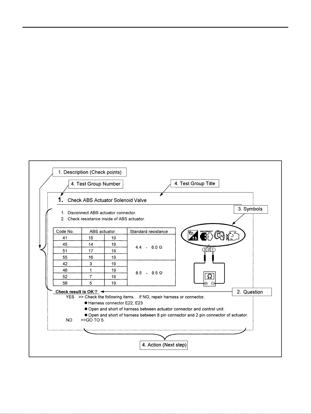
HOW TO FOLLOW TEST GROUPS IN TROUBLE DIAGNOSES
SAIA0256E
1. Work a nd diagnostic procedure
Start to diagnose a problem using procedures indicated in enclosed test groups.
2. Questions and required results
Questions and required results are indicated in bold type in test group.
The meaning of are as follows:
Revision: 2006 January 2006 M35/M45
GI-12
Page 19

HOW TO USE THIS MANUAL
a. Battery voltage → 11 - 14V or approximately 12V
b. Voltage : Approxima tely 0V → Less than 1V
3. Symbol used in illustration
Symbols included in illustrations refer to measurements or procedures. Before diagnosing a problem,
familiarize y ourself with ea ch symbol. R efer to "Connec tor Symbols" in GI Section a nd "KEY TO SYMBOLS SIGNIFYING MEASUREMENTS OR PROCEDURES" below.
4. Action items
Next action for ea ch te st gr o up is ind ic at e d base d on r es ult o f e ach qu es ti o n. Test group n umber i s sh own
in the left upper portion of each test group.
HARNESS WIRE COLOR AND CONNECTOR NUMBER INDICATION
There are two types of harness wire color and connector number indication.
TYPE 1: Harness Wire Color and Connector Number are Shown in Illustration
● Letter designations next to test meter probe indicate harness
wire color.
● Connector numbers in a single circle (e.g. M33) indicate har-
ness connectors.
● Connector numbers in a double circle (e.g. F211) indicate com-
ponent connectors.
GI
B
C
D
E
F
G
H
AGI070
I
J
K
L
M
Revision: 2006 January 2006 M35/M45
GI-13
Page 20

HOW TO USE THIS MANUAL
TYPE 2: Harness Wire Color and Connector Number are Shown in Text
KEY TO SYMBOLS SIGNIFYING MEASUREMENTS OR PROCEDURES
SGI144A
SAIA0750E
Revision: 2006 January 2006 M35/M45
GI-14
Page 21

HOW TO USE THIS MANUAL
GI
B
C
D
E
F
G
H
K
M
I
J
L
SAIA0751E
Revision: 2006 January 2006 M35/M45
GI-15
Page 22

HOW TO USE THIS MANUAL
How to Read Wiring Diagrams NAS0007N
CONNECTOR SYMBOLS
Most of connector symbols in wir ing diagrams are shown from the terminal sid e.
● Connector symbols shown from the terminal side are enclosed
by a single line and followed by the direction mark.
● Connector symbols shown from the harness side are enclosed
by a double line and followed by the direction mark.
● Certain systems and components, especially those related to
OBD, may use a new style slide-locking type harness connector.
For description and how to disconnect, refer to PG section,
“Description”, “HARNESS CONNECTOR”.
● Male and female terminals
Connector guides for male terminals are shown in black and
female terminals in white in wiring diagrams.
SAIA0257E
SGI363
Revision: 2006 January 2006 M35/M45
GI-16
Page 23

HOW TO USE THIS MANUAL
SAMPLE/WIRING DIAGRAM - EXAMPL -
● For detail, refer to following “DESCRIPTION”.
GI
B
C
D
E
F
G
H
K
M
I
J
L
SGI091A
Revision: 2006 January 2006 M35/M45
GI-17
Page 24

Optional Splice
HOW TO USE THIS MANUAL
DESCRIPTION
Num-
ber
1 Power condition
2 Fusible link
Fusible link/fuse loca-
3
tion
4Fuse
5 Current ra ting
6 Connectors
7 Optional splice
8 Splice
9 Page crossing
10 Common connector
11 Option abbreviation
12 Relay
13 Connectors
SGI942
Item Description
● This shows the condition when the system receives battery positive voltage (can be oper-
ated).
● The doubl e line shows that this is a fusible link.
● The open ci rc le sh ow s cur ren t flow in, and the shaded circle shows current flow out.
● This sho w s the loca tion of the fusibl e l ink or fuse in the fusi bl e link or fuse bo x. F or arrange-
ment, refer to PG section, POWER SUPPLY ROUTING.
● The sing le line shows that this is a fuse.
● The open ci rc le sh ow s cur ren t flow in, and the shaded circle shows current flow out.
● This sho w s the current rati ng of the fu si ble link or fuse .
● This sho ws tha t con nect or E3 is fem ale and connector M1 is male.
● The G/R wire is located in the 1A terminal of both connectors.
● Terminal number with an alphabet (1A, 5B, etc.) indicates that the connector is SMJ connec-
tor. Refer to PG section, SMJ (SUPER MULTIPLE JUNCTION).
● The open ci rc le sh ow s th at the spli ce is optional depending on vehicle application.
● The shaded circle shows that the splice is always on the vehicle.
● This arrow shows that the circuit continues to an adjacent page.
● The A will match with the A on the pre ceding or next page.
● The dotted lines between terminals show that these terminals are part of the same connector.
● This sho w s tha t the circu it is op tiona l dep endi ng on vehicle application.
● This sho ws an in ternal rep res entation of the relay. For details, refer to PG section, STAN-
DARDIZED RELAY.
● This sho w s tha t the conn ect or is connected to the body or a terminal with bolt or nut.
Revision: 2006 January 2006 M35/M45
GI-18
Page 25

HOW TO USE THIS MANUAL
Num-
ber
Item Description
14 Wire color
15 Option description
16 Switch
17 Assembly parts
18 Cell code
19 Current flow arrow
20 System branch
21 Page crossing
22 Shielded line
Component box in
23
wave line
24 Component name
25 Connector number
26 Ground (GND)
27 Ground (GND)
28 Connector views
29 Common component
30 Connector color
● This shows a code fo r th e color of the wire .
B = Black
W = White
R = Red
G = Green
L = Blue
Y = Yellow
LG = Light Green
BR = Brown
OR or O = Orange
P = Pink
PU or V (Violet) = Purple
GY or GR = Gray
SB = Sky Blue
CH = Dark Brown
DG = Dark Green
When the wire color is striped, the base color is given first, followed by the stripe color as shown
below:
Example: L/W = Blue with White Stripe
● This shows a description of the option abbreviation used on the page.
● This shows that cont i nui ty exi sts between te rmi nal s 1 and 2 w hen the sw i tch is in the A posi-
tion. Continuity exists between terminals 1 and 3 when the switch is in the B positio n.
● Conne cto r term i nal in component shows that it is a harness incorporated assembly.
● This ident ifies each page of the wiring diagram by section, system and wiring diagr am page
number.
● Arrow indicates electric current flow, especially where the direction of standard flow (vertically
downward or horizontally from left to right) is difficult to follow.
● A double arrow “ ” shows that current can flow in either direction depending on cir-
cuit operation.
● This shows that the system branches to another system ident i fied by ce ll code (section and
system).
● This arrow show s that the circuit continues to another page identified by cell code.
● The C will match with the C on another page within the system other than the next or preced-
ing pages.
● The line enclosed by broken line circle shows shield wire.
● This shows that anot her part of the component is also shown on another page (indicated by
wave line) within the system.
● This shows the nam e of a com ponent.
● This shows the con nect or number.
● The letter show s w hich harness the connector is located in.
● Example: M : main harness. For detail and to locate the connector, refer to PG section "Main
Harness", “Harness Layout”. A coordina te grid is included for complex harnesses to aid in
locating connectors.
● The line splice d and gr ounded under wire color shows that ground line is spliced at the
grounded connector.
● This shows the ground connection. For detailed ground distribution information, refer to
"Ground Distribution" in PG section.
● This area show s t he connector faces of the components in the wiring diagram on the page.
● Conne cto rs encl osed in broken line show that these connectors belong to the same compo-
nent.
● This shows a code for the color of the connector. For code meaning, refer to wire color codes,
Number 14 of this chart.
GI
B
C
D
E
F
G
H
I
J
K
L
M
Fusible link and fuse
31
box
32 Reference area
Revision: 2006 January 2006 M35/M45
● This shows the arrangement of fusible link(s) and fuse(s), use d for connector views of
"POWER SUPPLY ROUTING" in PG section.
The open square shows current flow in, and the shaded square shows current flow out.
● This shows that more information on the Super Multiple Junction (SMJ) and Joint Connectors
(J/C) exists on the PG section. Refer to "Reference Area" for details.
GI-19
Page 26

HOW TO USE THIS MANUAL
Harness Indication
● Letter designations next to test meter probe indicate harness
(connector) wire color.
● Connector numbers in a sing le circ le M3 3 indic ate ha rness co n-
nectors.
Component Indication
Connector numbers in a double circle F211 indicate component connectors.
Switch Positions
Switches are shown in wiring diagrams as if the vehicle is in the “normal” condition.
A vehicle is in the “normal” condition when:
● ignition switch is “OFF”,
● doors, hood and trunk lid/b ac k door are closed,
● pedals are not depressed, and
● parking brake is released.
AGI070
SGI860
Revision: 2006 January 2006 M35/M45
GI-20
Page 27

HOW TO USE THIS MANUAL
Detectable Lines and Non-Detectable Lines
In some wiring diagrams, two kind s of lin es , rep res en tin g w ire s, with different weight are used.
● A line with regula r weight (wider line) represents a “detectable
line for DTC (Diagnostic Trouble Code)”. A “detectable line for
DTC” is a circu it in which ECM can detect its malf unctions with
the on board diagnostic system.
● A line with less weight (thinner line) represents a “non-detect-
able line for DTC”. A “non-dete ctable line for DT C” is a circuit in
which ECM cannot detect its malfunctions with the on board
diagnostic system.
GI
B
C
D
E
F
G
SGI862-B
H
I
J
K
L
M
Revision: 2006 January 2006 M35/M45
GI-21
Page 28

HOW TO USE THIS MANUAL
Multiple Switch
The continuity of multiple switch is described in two ways as shown below.
● The switch ch art is used in schematic diagrams.
● The switch diagram is used in wiring diagrams.
SGI875
Revision: 2006 January 2006 M35/M45
GI-22
Page 29

HOW TO USE THIS MANUAL
Reference Area
The Reference Area of the wiring diagram contains references to additional electrical reference pages at the
end of the manual. If connector numbers and titles are shown in the Reference Area of the wiring diagram,
these connector symbols are not shown in the Connector Area.
GI
B
C
D
E
F
G
SGI092A
H
I
J
K
L
M
Revision: 2006 January 2006 M35/M45
GI-23
Page 30

HOW TO USE THIS MANUAL
Abbreviations NAS0007O
The followi ng ABBREVIATIONS are used:
ABBREVIATION DESCRIPTION
A/C Air Conditioner
A/T Automat ic Transaxle/Transmission
ATF Automatic Transmission Fluid
D
1 Drive range 1st gear
2 Drive range 2nd gear
D
3 Drive range 3rd gear
D
D
4 Drive range 4th gear
FR, RR Fro n t, Re ar
LH, RH Left-Hand, Right-Hand
M/T Manual Transaxle/Transmission
OD Overdrive
P/S Power Steering
SAE Society of Automotive Engineers, Inc.
SDS Service Data and Specifications
SST Special Service Tools
2WD 2-Wheel D rive
2 2nd range 2nd gear
2
1 2nd range 1st gear
2
2 1st range 2nd gear
1
1 1st range 1st gear
1
Revision: 2006 January 2006 M35/M45
GI-24
Page 31

SERVICE INFORMATION FOR ELECTRICAL INCIDENT
SERVICE INFORMATION FOR ELECTRICAL INCIDENT PFP:00000
How to Check Terminal NAS0007P
CONNECTOR AND TERMINAL PIN KIT
Use the connector and terminal pin kits listed below when replacing connectors or terminals.
The connector and terminal pin kits contain some of the most commonly used NISSAN/INFINITI connectors
and terminals. For detailed connector and terminal pin replacement procedures, refer to the latest NISSAN/
INFINITI CONNECTOR AND TERMINAL PIN SERVICE MANUAL.
Too l number
(Kent-Moore No.)
Tool name
(J38751-95NI)
Connector and terminal
pin kit (NISSAN)
(J38751-95INF)
Connector and terminal
pin kit (INFINITI)
(J42992-98KIT)
OBD and terminal repair
kit
(J42992-2000UPD)
OBD-II Connector Kit
Update
Description
WAIA0004E WAIA0005E
GI
B
C
D
E
F
G
H
HOW TO PROBE CONNECTORS
Connector damage and an intermittent connection can result from improperly probing of the connector during
circuit checks.
The probe of a digital multimeter (DMM) may not correctly fit the connector cavity. To correctly probe the connector, follow the procedures belo w using a “T” pin. For the b est contact grasp the “T” pin using an alligat or
clip.
Probing from Harness Side
Standard type (not waterproof type) connector should be probed
from harness side with “T” pin.
● If the connector has a rear cover such as a ECM connector,
remove the rear cover before probing the terminal.
● Do not probe waterproof connector from harness side. Damage
to the seal between wire and connector may result.
SGI841
Probing from Terminal Side
FEMALE TERMINAL
● There is a small notch abov e each fe male te rminal. Pro be each
terminal with the “T” pin through the notch.
Do not insert any ob ject other th an the same type male termin al
into female terminal.
I
J
K
L
M
SEL265V
Revision: 2006 January 2006 M35/M45
GI-25
Page 32

SERVICE INFORMATION FOR ELECTRICAL INCIDENT
● Some connectors do not have a notch above ea ch terminal . To
probe each terminal, remove the connector retainer to make
contact space for prob ing.
MALE TERMINAL
Carefully pr obe the cont act surface of each terminal using a “T” pin.
Do not bend terminal.
SEL266V
SEL267V
How to Check Enlarged Contact Spring of Terminal
An enlarged contact spring of a terminal may create intermittent signals in the circuit.
If the intermittent open circuit occurs, follow the procedure below to inspect for open wires and enlarged contact spring of female terminal.
1. Assemble a male terminal and approx. 10 cm (3.9 in) of wire.
Use a male terminal which matches the female terminal.
2. Disconnect the suspected faulty connector and hold it terminal
side up.
SEL270V
3. While holding the wire of the male terminal, try to insert the male
terminal into the female terminal.
Do not force the male terminal into the female terminal with
your hands.
SEL271V
Revision: 2006 January 2006 M35/M45
GI-26
Page 33

SERVICE INFORMATION FOR ELECTRICAL INCIDENT
4. While moving the connector, check whether the male terminal
can be easily inserted or not.
● If the male terminal can be easily inserted into the female termi-
nal, replace the female terminal.
GI
B
C
SEL272V
D
E
F
G
SEL273V
Waterproof Connector Inspection
If water enters the connector, it can short interior circuits. This may lead to intermittent problems.
Check the following items to maintain the original waterproof characteristics.
RUBBER SEAL INSPECTION
● Most waterproof connectors are provided with a rubber seal
between the male and female connectors. If the seal is missing,
the waterpro of performanc e may not meet specifications.
● The rubber seal may come off when connectors are discon-
nected. Whenev er connectors are reco nnected, make sure the
rubber seal is properly installed on either side of male or female
connector.
SEL275V
WIRE SEAL INSPECTION
The wire seal mu st be installed o n the wire insertion ar ea of a wate rproof conn ector. Be sure that the sea l is
installed properly.
Terminal Lock Inspection
Check for unlocked termina ls by pulling wire at the end of connector.
An unlocked terminal may create intermittent signals in the circuit.
H
I
J
K
L
M
SEL330V
Revision: 2006 January 2006 M35/M45
GI-27
Page 34

SERVICE INFORMATION FOR ELECTRICAL INCIDENT
How to Perform Efficient Diagnosis for a n Electrical I ncident NAS0007Q
WORK FLOW
SGI838
STEP DESCRIPTION
Get detailed information about the conditions and the environment when the incident occurred.
The following are key pieces of information required to make a good analysis:
WHAT Vehicle Model, Engine, Transmission/Transaxle and the System (i.e. Radio).
STEP 1
STEP 2
STEP 3
STEP 4
STEP 5 Repair or replace the incident circuit or component .
STEP 6
WHEN Date, Time of Day, Weather Conditions, Frequency.
WHERE Road Conditions, Altitude and Traffic Situation.
HOW
Operate the system, road test if necessary.
Verify the parameter of the incident.
If the problem cannot be duplicated, refer to “Inc id ent Simul ation Tests”.
Get the proper diagnosis materials tog eth er incl udi ng:
● Powe r Supply Rout i ng
● Syste m Oper at io n De scr ip tions
● Applicable Service Manual Sections
● Chec k fo r any Service Bul l etins
Identify where to begin diagnosis base d upon your knowledge of the system operation and the cu st om er com m ents.
Inspect the system for mechanical bi nding, loo se connectors or wiring damage.
Determine which circuits and components are involved and diagnose using the Power Supply Routing and Harness
Layouts.
Operate the system in all modes. Verify the system works properly under all conditions. Make sure you have not inadvertently created a new incident during your diagnosis or repair steps.
System Symptoms, Operating Conditi ons (Ot her Components Interaction).
Service History and if any After Market Accessories have been installed.
INCIDENT SIMULATION TESTS
Introduction
Sometimes the symptom is not present when the vehicle is brought in for service. If possible, re-create the
conditions present at the time of the incident. Doing so may help avoid a No Trouble Found Diagnosis. The following section illustrates ways to simulate the conditions/environment under which the owner experiences an
electrical incident.
The section is broken into the six following topics:
● V ehicle vibration
● Heat sensitive
Revision: 2006 January 2006 M35/M45
GI-28
Page 35

SERVICE INFORMATION FOR ELECTRICAL INCIDENT
● Freezing
● Water intrusion
● Electrical load
● Cold or hot start up
Get a thorough description of the incident from the customer. It is important for simulating the conditions of the
problem.
GI
B
Vehicle Vibration
The problem may occu r or be com e wors e wh ile dr iving on a roug h road or whe n eng ine i s vibrat in g (idl e with
A/C on). In such a case , you w ill wan t to ch eck f or a vib rati on rel ated con ditio n. Re fer to th e foll owing i llu stration.
CONNECTORS & HARNESS
Determine which con necto rs an d wirin g ha rness woul d affect t he elec trical s yste m yo u are insp ecti ng. G entl y
shake each connect or and harness while monit oring the system for the inciden t you are trying to duplicate.
This test may indicate a loose or poor electrical connection.
HINT
Connectors can be exposed to moi sture. It is possibl e to get a thin film of corrosion on the co nnector terminals. A visual inspection may not reveal this without disconnecting the connector. If the problem occurs intermittently, perhaps the problem is ca used by corrosi on. It is a good i dea to disco nnect, inspec t and clean the
terminals on related connectors in the system.
SENSORS & RELAYS
Gently apply a slight vibration to sensors and relays in the system you are inspecting.
This test may indicate a loose or poorly mounted sensor or relay.
C
D
E
F
G
H
I
J
SGI839
ENGINE COMPARTMENT
There are several reasons a vehicle or engine vibration could cause an electrical complaint. Some of the
things to check for are:
● Connectors not full y se ate d.
● Wiring harness not long enou gh and is being st ressed due to engine vibrations or rocking.
● Wires laying across brackets or moving components.
● Loose, dirty or corroded ground wires.
● Wires routed too clos e to ho t components.
To inspect componen t s u nd er th e ho od, start by ve rif yi ng t h e i nte gr it y o f gro un d con ne ct i ons. ( Re fer t o Gr ou nd
Inspection described later.) First check that the system is properly grounded. Then check for loose connection
by gently shak ing the wiring or comp onents as previously explained. Using th e wiring diagrams inspe ct the
wiring for continuity.
BEHIND THE INSTRUMENT PANEL
An improperly routed or improperly clamped harness can become pinched during accessory installation. Vehicle vibration can aggravate a harness which is routed along a bracket or near a screw.
K
L
M
Revision: 2006 January 2006 M35/M45
GI-29
Page 36

SERVICE INFORMATION FOR ELECTRICAL INCIDENT
UNDER SEATING AREAS
An unclamped or loose harness can cause wiring to be pinched by seat components (such as slide guides)
during vehicle vibrat ion. If the wiring runs under seating are as, inspect wire routing for possible damage or
pinching.
Heat Sensitive
The customer's concern may occur during h ot weather or after car
has sat for a short time. In such cases you will want to check for a
heat sensitiv e condition.
To determine if an electrical component is heat sensitive, heat the
component with a heat gun or equivalent.
Do not heat compo nents above 60°C (140°F). If incident occurs
while heating th e unit, either repla ce o r p rop erl y ins u late the component.
SGI842
Freezing
The customer may indicate the incident goes away after the car
warms up (wint e r tim e) . T he c au se co ul d be r el a ted to wa te r fr ee zi ng
somewhere in the wiring/electrical system.
There are two me thods to check for this. The first is to arra nge for
the owner to leave his car overnight. Make sure it will get cold
enough to demonstrate his complaint. Leave the car parked outside
overnight. In the morning, do a quick and thorough diagnosis of
those electrical components which could be affected.
The second m ethod is to put the sus pect component int o a freezer
long enough for any water to freeze. Reinstall the part into the car
and check for the re occurrence of the inci dent. If it o ccurs, repair or
replace the compone nt .
SGI843
Water Intrusion
The incident may occur only during high humidity or in rainy/snowy
weather. In such cases the in cident could be c aused by wa ter intrusion on an electrical part. This can be simulated by soaking the car
or running it through a car wash.
Do not spray water directly on any electrical components.
Electrical Load
The incident may be electrical load sensitive. Perform diagnosis with
all accessories (including A/C, rear window defogger, radio, fog
lamps) turned on.
SGI844
SGI845
Revision: 2006 January 2006 M35/M45
GI-30
Page 37

SERVICE INFORMATION FOR ELECTRICAL INCIDENT
Cold or Hot Start Up
On some occas ions an elec trical incide nt may occur on ly when the ca r is started col d, or it may oc cur when
the car is restarted hot shortly after being turned off. In these cases you may have to keep the car overnight to
make a proper diagno sis.
CIRCUIT INSPECTION
Introduction
In general, testing electrical circuits is an easy task if it is approached in a logical and organized method.
Before beginning it is important to have all available information on the system to be tested. Also, get a thorough understanding of system opera tion. Then you will be able to use the approp riate equipm ent and follow
the correct test procedure.
Yo u may hav e to sim ulate vehi cle v ibr ation s whil e test ing e lectri cal c ompo nents. Ge ntly s hak e the wi ring h arness or electrical component to do this.
GI
B
C
D
OPEN A circ ui t is open when there is no continuity through a section of the circuit.
There are two types of shorts.
SHORT
● SHORT CIRCUIT
● SHORT TO GROUND When a circuit contacts a ground source and grounds the circuit .
When a circuit contacts another circuit and causes the norm al resistanc e to
change.
NOTE:
Refer to “How to Check Terminal” to probe or check terminal.
Testing for “Opens” in the Circuit
Before you begin to diagnose and test the system, you should rough sketch a schematic of the system. This
will help you to logically walk through the diagnosis process. Drawing the sketch will also reinforce your working knowledge of the system.
SGI846-A
CONTINUITY CHECK METHOD
The continuity check is used to find an open in the circuit. The digital multimeter (DMM) set on the resistance
function will indicate an open circuit as over limit (no beep tone or no ohms symbol). Make sure to always start
with the DMM at the highest resistance level.
To help in understanding the diagnosis of open circuits, please refer to the previous schematic.
● Disconnect the ba tte ry ne gative cable.
● Start at one end of the circuit and work your way to the other end. (At the fuse block in this example)
● Connect one probe of the DMM to the fuse block terminal on the load side.
● Connect the ot her probe to the fuse b lock (power) side of SW1. Little or no resis tance will indicate th at
portion of the circuit has good continuity. If there were an open in the circuit, the DMM would indicate an
over limit or infinite resistance condition. (point A)
● Connect the prob es be tw ee n SW 1 an d th e re la y. Little or no resistance wil l ind ic at e th at p ort ion of th e c ir-
cuit has good conti nuity. If there were an open in the circuit, the DMM would in dicate an over limi t or infinite resist ance condition. (point B )
● Connect the probes between the relay and the solenoid. Little or no resistance will indicate that portion of
the circuit ha s g oo d co nt inu it y. If there were an open in t he cir cu it , th e DM M w o uld i n di ca te an ov er l im it o r
infinite resi stance condition. (point C)
Any circuit can be diagnosed using the approach in the previous example.
E
F
G
H
I
J
K
L
M
Revision: 2006 January 2006 M35/M45
GI-31
Page 38

SERVICE INFORMATION FOR ELECTRICAL INCIDENT
VOLTAGE CHECK METHOD
To help in understanding the diagnosis of open circuits please refer to the pre vious schemati c.
In any powered circu it, an open can b e fou nd by method ical ly ch ecki ng the syste m for t he p res ence of volt a ge.
This is done by switching the DMM to the voltage function.
● Connect o ne probe of the DMM to a known good ground.
● Begin probing at one end of t he circuit and work your way to the other end.
● With SW1 open, probe at SW1 to check for voltage.
voltage; open is further down the circuit than SW1.
no voltage; open is between fuse block and SW1 (point A).
● Close SW1 and probe at relay.
voltage; open is furth er down the circ uit than the relay.
no voltage; open is between SW1 and relay (point B).
● Close the relay and probe at the solenoid.
voltage; open is further down the circuit than the solenoid.
no voltage; open is between relay and solenoid (point C).
Any powered circuit can be diagnosed using the approach in the previous example.
Testing for “Shorts” in the Circuit
To simplify the discussion of shorts in the system, please refer to the following schematic.
SGI847-A
RESISTANCE CHECK METHOD
● Disconnect the battery negative cable and remove the blown fuse.
● Disconnect all loads (SW1 open, relay disconnected and solenoid disconnected) powered through the
fuse.
● Connect one probe of the DMM to the load side of the fuse terminal. Connect the other probe to a known
good ground.
● With SW1 open, check for continuity.
continuity; short is between fuse terminal and SW1 (point A).
no continuity; short is further down the circuit than SW1.
● Close SW1 and disconn ect the relay. Put probes at the load side of fuse terminal and a known good
ground. Then, check for continuity.
continuity; short is between SW1 and the relay (point B).
no continuity; short is further down the circuit than the relay.
● Close SW1 and jump the relay contacts with jumpe r wire. Put probes at the load side of fuse terminal and
a known good ground. Then, check for continuity.
continuity; short is between relay and solenoid (point C).
no continuity; check solenoid, retrace steps.
VOLTAGE CHECK METHOD
● Remove the bl own fus e and d is con ne ct al l loa ds (i. e. SW 1 ope n, rel ay d is con nect e d an d sole no id di scon-
nected) powered through the fuse.
● Turn the ignition key to the O N or START position. Verify battery voltage at the ba ttery + s ide of the fuse
terminal (on e l ead on th e b at ter y + term in al side of th e fus e b lo ck a nd on e lead on a kn own goo d g rou nd ).
● With SW1 open and the DMM leads across both fuse terminals, check for voltage.
voltage; short is between fuse block and SW1 (point A).
Revision: 2006 January 2006 M35/M45
GI-32
Page 39

SERVICE INFORMATION FOR ELECTRICAL INCIDENT
no voltage; short is further down the circuit than SW1 .
● With SW1 closed, relay and solenoid disconnected and the DMM leads across both fuse terminals, check
for voltage.
voltage; short is between SW1 and the relay (point B).
no voltage; short is further down the circuit than the relay.
● With SW1 closed, relay contacts jumped with fused jumper wire check for voltage.
voltage; short is down the circuit of the relay or between the relay and the disconnected solenoid (point C).
no voltage; retrace steps and check power to fuse block.
Ground Inspection
Ground connections are very important to the proper operation of electrical and electronic circuits. Ground
connections are often exposed to moisture, dirt and other corrosive elements. The corrosion (rust) can
become an unwant ed resistance. This unwanted resistance can change the way a circuit works.
Electronical ly cont rol l ed ci rcui t s a r e ve ry se ns it ive to prop er gr ou ndin g. A lo ose or co r rod ed gro un d ca n d rast ically affect an elec tronically controlled circui t. A poor or corroded ground c an easily affect the circuit. Eve n
when the groun d connection lo oks clean, there can be a thin film of rust on the surface.
When inspecting a ground connection follow these rules:
● Remove the ground bolt or screw.
● Inspect all mating surfaces for tarnish, dirt, rust, etc.
● Clean as required to assure good contact.
● Reinstall bolt or screw securely.
● Inspect for “add-on” accessories which may be interfering with the ground circuit.
● If several wires are crimped into one ground eyelet terminal, check for proper crimps. Make sure all of the
wires are clean, securely fastened and providing a good ground path. If multiple wires are cased in one
eyelet make sure no ground wires have excess wire insulation.
For detailed ground distribution information, refer to “Ground Distribution” in PG section.
GI
B
C
D
E
F
G
H
SGI853
Vo ltage Drop Tests
Voltage drop tests are often used to find co mponents or circuits whic h have excessiv e resistance. A voltage
drop in a circuit is caused by a resistance when the circuit is in operation.
Check the wire in the illustration. When measuring resistance with DMM, contact by a single strand of wire will
give reading of 0 ohms. This would indicate a good circuit. When the circuit operates, this single strand of wire
is not able to carry the current. The single strand will have a high resistance to the current. This will be picked
up as a slight voltage drop.
Unwanted resistance can be caused by many situations as follows:
● Undersized wiring (single strand example)
● Corrosion on switch contacts
● Loose wire connec tions or splic es.
I
J
K
L
M
Revision: 2006 January 2006 M35/M45
GI-33
Page 40

SERVICE INFORMATION FOR ELECTRICAL INCIDENT
If repairs are needed always use wire that is of the same or larger gauge.
MEASURING VOLTAGE DROP — ACCUMULATED METHOD
● Connect the DMM ac ross the co nnector or part of the circ uit you wa nt to check. The posit ive lead of t he
DMM should be closer to power and the negative lead closer to ground.
● Operate the circuit.
● The DMM will indicate how many volts are being used to “push” current through that p art of the circuit.
Note in the illustration that there is an excessive 4.1 volt drop between the battery and the bulb.
SGI974
MEASURING VOLTAGE DROP — STEP-BY-STEP
The step-by-step method is most useful for isolating excessive drops in low voltage systems (such as those in
“Computer Controlled Systems”).
Circuits in the “Computer Controlled System” operate on very low amperage.
The (Computer Controlled) system operations can be adversely affected by any variation in resistance in the
system. Such resistance variation may be caused by poor connection, improper installation, improper wire
gauge or corros ion.
The step by step v oltage drop test can identi fy a component or wire with too much resistance.
SAIA0258E
Revision: 2006 January 2006 M35/M45
GI-34
Page 41

SERVICE INFORMATION FOR ELECTRICAL INCIDENT
Control Unit Circuit Test
System Description:When the switch is ON, the control unit lights up the lamp.
GI
B
C
D
MGI034A
INPUT-OUTPUT VOLTAGE CHART
Pin
No.
1 Switch
2Lamp
The voltage value is based on the body ground.
*:If high resistance exists in the switch side circu it (caused by a single stran d), terminal 1 doe s not detect ba ttery voltage. Control unit
does not detect the s witch is ON even i f the switch does n ot turn ON . Therefore, the contro l unit doe s not su pply power t o light up the
lamp.
Item Condition
Switch ON Battery voltage Lower than battery voltage Approx. 8 (Example)
Switch OFF Approx. 0 Approx. 0
Switch ON Battery voltage Approx. 0 (Inoperative lamp)
Switch OFF Approx. 0 Approx. 0
Voltage
value [V]
In case of high resistance such as single strand [V ] *
MGI035A
E
F
G
H
I
J
K
L
INPUT-OUTPUT VOLTAGE CHART
Pin
No.
1 Lamp
2Switch
The voltage value is based on the body ground.
*:If high resistance exists in the swi tch side circuit ( caused by a s ingle stran d), ter minal 2 does not dete ct approx. 0V. Control unit d oe s
not detect the switch is ON even if the switch does not turn O N. Ther ef ore , the cont r ol unit does not control ground to light up the lamp.
Item Condition
Switch ON Approx. 0 Battery voltage (Inoperative lamp)
Switch OFF Battery voltage Batte ry vo ltage
Switch ON Approx. 0 Higher than 0 Approx. 4 (Example)
Switch OFF Approx. 5 Approx. 5
Revision: 2006 January 2006 M35/M45
Voltage
value [V]
In case of high resistance such as single strand [V] *
GI-35
M
Page 42

SERVICE INFORMATION FOR ELECTRICAL INCIDENT
Control Units and Electrical Parts NAS0008L
PRECAUTIONS
● Never reverse polarity of battery terminals.
● Install only parts specified for a vehicle.
● Before replacing the control unit, check the input and output and
functions of the component parts.
● Do not apply excessive force when disconnecting a connector.
● If a connector is ins talled by tigh tenin g bo lts, loos en bo lt mo unt-
ing it, then take it out by hand.
SAIA0251E
● Before installing a connecto r, make sure the terminal is not ben t
or damaged, and then correc t ly conne c t it .
When installing a con nector by tightening bolts, fix it b y tightening the mount ing bolt u ntil the pain ted projec tion of th e connec tor becomes even with the surface.
● For removal of the l ever type connector, pull the leve r up to th e
direction pointed to by the arrow A in the figure, and then
remove the connector.
● For installation of the lever type connector, pull down the lever to
the direction poin ted by the ar row B in th e figure , and the n push
the connector until a clicking noise is heard.
SAIA0252E
SAIA0253E
SAIA0254E
Revision: 2006 January 2006 M35/M45
GI-36
Page 43

SERVICE INFORMATION FOR ELECTRICAL INCIDENT
● Do not apply excessive shock to the control unit by dropping or
hitting it.
● Be careful to prevent condensation in the control unit due to
rapid temperatur e c ha ng es an d do not let water or rain get o n it .
If water is found in the control unit, dry it fully and then install it in
the vehicle.
● Be careful not to let oil to get on the control unit connector.
● Avoid clea ning the control unit with volatile oil.
● Do not disassemble the control unit, and do not remove the
upper and low er covers.
● When using a DMM, be careful not to let test probes get close to
each other to prevent the power transistor in the control unit
from damaging battery voltage because of short circuiting.
● When checking input and output signals of the control unit, use
the specified check adapter.
GI
B
C
SAIA0255E
D
E
F
G
SEF348N
H
I
J
K
L
M
Revision: 2006 January 2006 M35/M45
GI-37
Page 44

CONSULT-II CHECKING SYSTEM
CONSULT-II CHECKING SYSTEM PFP:00000
Description NAS0007S
● CONSULT-II i s a han d-hel d typ e tes ter. When it is connected with a diagno sti c conn ect or equi pped on th e
vehicle side, it will communicate with the control unit equipped in the vehicle and then enable various
kinds of diagnosti c tes ts.
● Refer to “CONSULT-II Software Operation Manual” for more information.
Function and Sys tem Application NAS0007T
Diagnostic test
mode
This mode enables a technician to adjust
Work support
Self-diagnostic
results
Trouble diagnostic record
Data monitor Input/Output data in the ECU can be read. x x - x x x x - x x x x x x x x x x
CAN diagnosis
support monitor
Active test
DTC & SRT confirmation
DTC work support
ECU (ECM/TCM)
part number
ECU discriminated No.
Function test
Control unit initialization
AV COMM monitor
x: Applicable
*: NISSAN Anti-Theft System (INFINITI/NISSAN Vehicle Immobilizer System)
some devices faster and more accurat el y by
following the indications on CONSULT-II.
Self-diagnostic results can be read and
erased quickly.
Current self-diagnostic results and all trouble
diagnostic records previously st or ed can be
read.
The condition of CAN communica tion lin e
can be read.
Diagnostic Test Mode in which CONSULT -II
drives some actuators apart from the ECUs
and also shifts some parameters in a specified range.
The results of SRT (System Readiness T est)
and the self-diagnosis status/result can be
confirmed.
The operating condition to confirm Diagnosis
Trouble Codes can be selected.
ECU (ECM/TCM) part number can be read. x x - - x x x - - x x x x x x x x x
Classification number of a replacemen t ECU
can be read to prevent an incorrect ECU from
being installed.
This mode can show results of self-diagnosis
of ECU with either 'OK' or 'NG'. For engines,
more practical tests regarding sensors/
switches and/or actuators are available.
All registered ignition key IDs in NATS components can be initialized and new IDs can
be registered.
The condition of AV communication can be
Indicated.
Function
A/T
ENGINE
x---xxx-- x-xxx-x- -
xxxxxxxxxxxxxxxxxx
--x---------------
xx-xxxx- xxxxxxxxxx
x- --xxx-xxxxxxxx--
x-----------------
xx----------------
--x---------------
xxx---x-----------
-------x----------
-----------------x
AIR BAG
METER A/C AMP
BCM
AUTO DRIVE POS.
ABS (Including VDC)
ICC
IPDM E/R
NATS (IVIS/NATS) *
INTELLIGENT KEY
ALL MODE AWD/4WD
LDW
RAS/HICAS
ADAPTIVE LIGHT
AIR PRESSURE MONITOR
MULT I AV
PRECRASH SEATBELT
Revision: 2006 January 2006 M35/M45
GI-38
Page 45

CONSULT-II CHECKING SYSTEM
Nickel Metal Hydride Battery Replacement NAS0007U
CONSULT-II contains a nickel metal hydride battery. When replacing the battery obey the following:
WARNING:
Replace the nickel metal hydride battery with Genuine CONSULT-II battery only. Use of another battery may present a risk of fi re or explos ion. The battery may present a f ire or che mical bu rn hazard if
mistreated. Do not recharge, disassemble or dispose of in fire.
Keep the battery out of reach of children and discard used battery conforming to the local regulations.
Checking Equipment NAS0007V
When ordering the following equipment, contact your NISSAN/INFINITI distributor.
Tool nam e Description
GI
B
C
D
NISSAN CONSULT-II
1.CONSULT-II unit (Tes te r internal sof t: Resi dent
version 3.3.0) and accessories
2.Program card UED05B and AEN04A-1 (For
NATS)
3.CONSULT-II CONVERTER
4.“CONSULT-II Pigtail” Cable
SAIA0363E
NOTE:
● The CONSULT-II must be used in conj unction with a p rogram card.
CONSULT-II does not require loading (Initialization) procedure.
● Be sure the CONSULT-II is turned off before installing or removing a program card.
CAUTION:
● If CONSULT-II is used with no connection of CONSULT-II CONVERTER, malfunctions might be
detected in self-diagnosis depending on control unit which carry out CAN communication.
● If CONSULT-II CONVERTER is not connected with CONSULT-II, vehicle occur the “FAIL SAFE
MODE” which is “LIGHT UP the HEAD LIGHT” and/or “COOLING FAN ROTATING” when CONSULT-II is started.
● Previous CONSULT-II “I” and “Y” DLC-I and DLC-II cables should NOT b e used a nymore beca use
their DDL connector pins can be damaged during cable swapping.
CONSULT-II Start Procedure NAS0007W
E
F
G
H
I
J
K
L
NOTE:
Turning ignition switch off when performing CAN diagnosis could cause CAN memory to be erased.
1. Connect CONSULT-II and CONSULT-II CONVERTER to the
data link co nnector.
PAIA0070E
Revision: 2006 January 2006 M35/M45
GI-39
M
Page 46

CONSULT-II CHECKING SYSTEM
2. If necessary, turn on the ignition switch.
3. Touch “START (NISSAN BASED VHCL)” or “System Shortcut”
(eg: ENGINE) on the scree n .
4. Touch necessary system on "SELECT SYSTEM" screen.
If necessary system is not indicated, check power supply and
ground of system control unit. If it is normal, refer to GI-40,
"CONSULT-II Data Link Connector (DLC) Circuit" .
SAIA0450E
BCIA0030E
5. Select the desired part to be diagnosed on the "SELECT DIAG
MODE" screen.
BCIA0031E
CONSULT-II Data Link Connector (DLC) Circuit NAS0007X
INSPECTION PROCEDURE
If the CONSULT-II cannot diagnose the system properly, check the following items.
Symptom Check item
CONSULT-II cannot access
any system.
CONSULT-II cannot access
individual system. (Other systems can be accessed.)
● CONSULT-II DLC power supply circuit (Terminal 8) and ground circuit (Terminal 4) (For detailed
circuit, refer to “MIL & Data Link Connectors Wiring Diagram” in EC section.)
● CONSULT-II DLC cable and CONSULT-II CONVERTER
● CONSULT-II program card (Check the appropriate CONSULT-II program card for the system.
Refer to "Checking Equipment".)
● Power supply and ground circuit for the control unit of the system (For detailed circuit, refer to wir-
ing diagram for each system.)
● Open or short circuit between the system and CONSULT-II DLC (For detailed circuit, refer to wiring
diagram for each system.)
● Open or short circuit CAN communication line. Refer to LAN-7, "Precautions When Using CON-
SULT-II" .
NOTE:
The DDL1 and DDL2 circuits from DLC pins 12, 13, 14 and 15 may be connected to more than on e system. A
short in a DDL circuit connected to a control unit in one system may affect CONSULT-II access to other systems.
Revision: 2006 January 2006 M35/M45
GI-40
Page 47

CIRCUIT DIAGRAM
CONSULT-II CHECKING SYSTEM
GI
B
C
D
E
F
G
H
K
M
I
J
L
TAWT0033E
Revision: 2006 January 2006 M35/M45
GI-41
Page 48

LIFTING POINT
LIFTING POINT PFP:00000
Special Service Tools NAS0007Y
The actual shapes of Kent-Moore tools may differ from those of special service tools illustrated here.
Too l number
(Kent-Moore No.)
Tool name
LM4086-0200
( - )
Board on at tachment
LM4519-0000
( - )
Safety stan d attachmen t
Description
S-NT001
S-NT002
CAUTION:
● Every time the vehicle is lifted up, maintain the complete vehicle curb condition.
● Since the vehicle's center of gravity change s w he n remo vi ng ma in parts on the front side (engine,
transmission, suspension etc.), support a jack up point on the rear side garage jack with a mission
jack or equivalent.
● Since the veh icle's cen ter o f grav it y chan ges when remov ing m ain p arts on the rear side (rear axl e,
suspension, etc.), support a jack up point on the front side garage jack with a mission jack or
equivalent.
● Be careful not to smash or do not do anything that would affect piping parts.
Garage Jack and Safety Stand and 2-Pole Lift NAS0007Z
WARNING:
● Park the vehicle on a level surface when using the jack. Make sure to avoid damaging pipes,
tubes, etc. under the vehicle.
● Never get under the ve hic le while it is supp or ted only by the jack. Al w ay s u se s afe ty stands when
you have to get under the vehicle.
● Place wheel chocks at both front and back of the wheels on the ground.
● When lifting the vehicle, open the lift arms as wide as possible and ensure that the front and rear
of the vehicle are well balanced.
● When setting the lift arm, do not allow the arm to contact the brake tubes, brake cable, fuel lines
and sill spoiler.
Revision: 2006 January 2006 M35/M45
GI-42
Page 49

LIFTING POINT
1. Safety stand point and lift up point (front) 2. Safety stand point and lift up point
(rear)
4. Garage jack point (rear)
GI
B
C
D
E
F
PIIB3129E
3. Garage jack point (front)
G
CAUTION:
There is canister just behind Garage jack point rear. Jack up be carefully.
Board-On Lift NAS00080
CAUTION:
Make sure vehicle is empty when lifting.
● The board-on lift attachment (LM408 6-0200) s et at front en d
of vehicle should be set on the front of the sill u nder the
front door opening.
● Position attachments at front and rear ends of board-on lift.
AGI016
H
I
J
K
L
M
Revision: 2006 January 2006 M35/M45
GI-43
Page 50

TOW TRUCK TOWING
TOW TRUCK TOWING PFP:00000
Tow Tr uck Towing NAS00081
CAUTION:
● All applicable state or Provi ncial (in Cana da) laws and lo cal laws rega rding the tow ing operation
must be obeyed.
● It is necessary to use prop er towing equipment to avoid possible damage to the vehicle during
towing operation. Towing is in accordance with Towing Procedure Manual at dealer.
● Always attach safety chains befor e towing.
● When towing, make sure that the transmissio n, ste erin g system and po we rtrai n are in good order.
If any unit is damaged, dollies must be used.
● Never tow an automatic transmissi on model from the rear (that is b ackward) with four wheels on
the ground. This may cause serious and expensive damage to the transmission.
2WD MODELS
PIIB6402E
INFINITI recommends that vehicle be towed with the driving (rear) wheels off the ground or that a dolly be
used as illustrated.
CAUTION:
● Never tow automatic transmission m odels with the rear wheels on the ground or four wheels on
the ground (forward or backward), as thi s may caus e serious a nd expe nsive dam age to the trans mission.
If it is necessary to tow the vehicle with the front wheels raised, always use towing dollies under
the rear wheels.
● When towing rear wheel drive models with the front wheels on the ground or on towing dollies:
– Turn the ignition key to the OFF position , and secure the ste ering whee l in a straight ahead posi-
tion with a rop e or si milar dev ice.N ever secur e the ste ering wh eel by tu rnin g the i gniti on key to th e
LOCK position. This may damage the steering lock mechanism.
– Move the selector lever to the N (Neutral) position.
● When the battery of vehicle equ ipped with the Intel ligent Key system is discharged , your vehicle
should be towed with the front wheels on towing dollies or place the vehicle on a flat bed truck.
If the speed or distance must necessarily be greater, remove the propeller shaft before towing to prevent damage to the transmission.
Revision: 2006 January 2006 M35/M45
GI-44
Page 51

AWD MODE LS
TOW TRUCK TOWING
GI
B
C
D
E
F
PIIB6403E
INFINITI recommends that a dolly be used as illustrated when towing AWD models.
CAUTION:
Never tow AWD models with any of the wheels on the grou nd as this may cause serious and expensive damage to the powertrain.
Vehicle Recovery (Freein g a Stuck Vehicle) NAS00082
FRONT
Securely install the vehicle recovery hook stored with jacking tools.
Make sure that the hook is properly secured in the stored place after
use.
WARNING:
● Stand clear of a stuck vehicle.
● Do not spin your tires at high speed. This could cause them
to explode and result in serious injury. Parts of your vehicle
could also overheat and be damaged.
CAUTION:
● Tow chains or cables must be attached only to the vehicle
recovery hook s or main str uctural memb ers of the vehic le.
Otherwise, the vehicle body will be damaged.
● Do not use the vehicle tie downs to free a vehicle stuck in sand, sn ow, mud, etc. Never tow the
vehicle using the vehicle tie dow ns or recove ry hook s.
● Always pull the cable straight out from the front of the vehicle. Never pull on the hook at an angle.
● Pulling devices should be routed so they do not touc h any part of the suspension, steering, brake
or cooling systems.
● Pulling devices such as ropes or canvas straps are not recommended for use in vehicle towing or
recovery.
PIIB3130E
G
H
I
J
K
L
M
REAR
WARNING:
● Rear hook is not available.
Revision: 2006 January 2006 M35/M45
GI-45
Page 52

TOW TRUCK TOWING
AUTOMATIC TRANSMISSION
To tow a vehicle equipped with an automatic transmission, an appropriate vehicle dolly MUST be placed
under the towed vehicle's drive w h ee ls . Always follow the dolly manufacture's recommendations when using
their produ c t.
If the vehicle is stuck in sand, snow, mud, etc., use the following procedure:
1. Turn off the Vehicle Dynamic Control System.
2. Make sure the area in front and behind the vehicle is clear of obstructions.
3. Turn the steering wheel right and left to clear an area around the front tires.
4. Slowly rock the vehicle forward and backward.
Shift back and forth between R (reverse) and D (drive).
Apply the acc elerator as little as possible to maintain the rocking motion.
Release the accelerator pe dal before shifting between R and D.
Do not spin the tires above 35 mph (55 km/h).
5. If the vehicle can not be freed after a few tries, contact a professional towing service to remove the vehicle.
Revision: 2006 January 2006 M35/M45
GI-46
Page 53

TIGHTENING TORQUE OF STANDARD BOLTS
TIGHTENING TORQUE OF STANDARD BOLTS PF P:00000
Tightening Torque Table NAS00083
GI
Bolt diam-
Grade Bolt size
M6 6.0 1.0 5.5 0.56 4 49 7 0.71 5 62
M8 8.0
4T
7T
9T
*: Nominal diameter
1. Special parts are excluded.
2. This standard is applicable to bolts having the following marks embossed on the bolt head.
M10 10.0
M12 12.0
M14 14.0 1.5 80 8.2 59 — 100 10 74 —
M6 6.0 1.0 9 0.92 7 80 11 1.1 8 97
M8 8.0
M10 10.0
M12 12.0
M14 14.0 1.5 130 13 96 — 170 17 125 —
M6 6.0 1.0 11 1.1 8 — 13.5 1.4 10 —
M8 8.0
M10 10.0
M12 12.0
M14 14.0 1.5 170 17 125 — 210 21 155 —
eter *
mm
Pitch
mm
N·m kg-m ft-lb in-lb N·m kg-m ft-lb in-lb
1.25 13.5 1.4 10 — 17 1.7 13 —
1.0 13.5 1.4 10 — 17 1.7 13 —
1.5282.921—353.626—
1.25 28 2.9 21 — 35 3.6 26 —
1.75 45 4.6 33 — 55 5.6 41 —
1.25 45 4.6 33 — 65 6.6 48 —
1.25 22 2.2 16 — 28 2.9 21 —
1.0222.216—282.921—
1.5454.633—555.641—
1.25 45 4.6 33 — 55 5.6 41 —
1.75 80 8.2 59 — 100 10 74 —
1.25 80 8.2 59 — 100 10 74 —
1.25 28 2.9 21 — 35 3.6 26 —
1.0282.921—353.626—
1.5555.641—808.259—
1.25 55 5.6 41 — 80 8.2 59 —
1.75 100 10 74 — 130 13 96 —
1.25 100 10 74 — 130 13 96 —
Hexagon head bolt Hexagon flange bolt
Tightening torque (Without lubricant)
B
C
D
E
F
G
H
I
J
K
L
M
MGI044A
Revision: 2006 January 2006 M35/M45
GI-47
Page 54

RECOMMENDED CHEMICAL PRODUCTS AND SEALANTS
RECOMMENDED CHEMICAL PRODUCTS AND SEALANTS PFP:00000
Recommended Chemical Products and Sealants NAS00084
Refer to the fo llowing chart for help in selecting the appr opriate chemical product or sealant.
Product Description Purpose
Rear View Mirror
1
Adhesive
Anaerobic Liquid Gas-
2
ket
High Performance
3
Thread Sealant
4 Silicone RTV
High Temperature,
5
High Strength Thread
Locking Sealant (Red)
Medium Strength
6
Thread Locking Sealant (Blue)
Used to permanently
remount rear view mirrors
to windows.
For metal-to-metal flange
sealing.
Can fill a 0.38 mm (0.015
inch) gap and provide
instant sealing for most
powertrain applications.
Provides instant sealing on
any threaded straight or
parallel threaded fitting.
(Thread sealant only, no
locking ability.)
● Do not use on plastic.
Gasket Maker
Gasket Maker for Maxi ma /
Quest 5-speed automatic
transmission
(RE5F22A)
Threadlocker 999MP-AM004P 999MP-AM 004P
Threadlocker (service tool
removable)
Nissan North America
Part No. (USA)
999MP-AM000P 99998-50505 Permatex 81844
999MP-AM001P 99998-5 0503
999MP-AM002P 999MP-AM002P Permatex 56521
999MP-AM003P
(Ultra Grey)
––
999MP-AM005P 999MP-AM005P
Nissan Canada Part
No. (Canada)
99998-50506
(Ultra Grey)
Aftermarket Cross-
reference Part Nos.
Permatex 51813 and
51817
Permatex Ultra Grey
82194;
Three Bond
1207,1215, 1216,
1217F, 1217G and
1217H
Nissan RTV Part No.
999MP-A7007
Three Bond 1281B
or exact equivalent
in its quality
Permatex 27200;
Three Bond 1360,
1360N, 1305 N&P,
1307N, 1335,
1335B, 1363B,
1377C, 1386B, D&E
and 1388
Loctite 648
Permatex 24200,
24206, 24240,
24283 and 09178;
Three Bond 1322,
1322N, 1324 D&N,
1333D, 1361C,
1364D, 1370C and
1374
Revision: 2006 January 2006 M35/M45
GI-48
Page 55

IDENTIFICATION INFORMATION
IDENTIFICATION INFORMATION PFP:00010
Model Variation NAS00085
GI
Body Engine Transmission G rade Axle
Sedan
VQ35DE
VK45DE 2-wheel drive BPHALRN-EUA BPHALRN-ENA
RE5R05A
(5A/T)
Base
Prefix and suffix designations:
Destination
USA CANADA
2-wheel drive BLJALRN-EUA BLJALRN-ENA
All-wheel drive BLJNLRN-EUA BLJNLRN-ENA
B
C
D
E
F
G
H
SAIA0758E
I
J
K
L
M
Revision: 2006 January 2006 M35/M45
GI-49
Page 56

IDENTIFICATION INFORMATION
IDENTIFICATION NUMBER
1. Vehicle identification number plate 2. Vehicle identification number (Chassis num ber)
3. Emission control information label 4. Vehicle identification plate
5. Air conditioner specification label 6. Tire and loading information label
7. FMVSS certification label
SAIA0902E
VEHICLE Identification Number ARRANGEMENT
SAIA0760E
Revision: 2006 January 2006 M35/M45
GI-50
Page 57

IDENTIFICATION PLATE
IDENTIFICATION INFORMATION
GI
B
C
ENGINE SERIAL NUMBER
SGI315
PAIA0110E
PAIA0111E
D
E
F
G
H
I
J
K
AUTOMATIC TRANSMISSION NUMBER
PAIA0054E
Revision: 2006 January 2006 M35/M45
GI-51
L
M
Page 58

IDENTIFICATION INFORMATION
Dimensions NAS00086
Unit: mm (in)
Overall length
Overall width 1,798 (70.8)
Overall height 1, 508 (5 9.4 )*1, 1,523 (6 0. 0)* 2
Front tread 1,537 (60.5)*1, 1,551 (61.1)*2
Rear tread 1,550 (61.0)*1, 1,543 (60.7)*2
Wheelbase 2, 900 (114.2)
*1: 2-wheel drive model
*2: All-wheel drive model
without front license plate 4,893 (192.6)
with front license plate 4, 899 (1 92. 9)
Wheels & Tires NAS00087
Conventional Spare
Road wheel/offset mm (in)
Tire size
*: 2-wheel drive model
18 X 8JJ Aluminum/47 (1.85)
19 X 8.5JJ Aluminum/50 (1.97)*
P245/45R18
245/40R19*
17x4T/30 (1.18)
T145/80D17
Revision: 2006 January 2006 M35/M45
GI-52
Page 59

TERMINOLOGY
TERMINOLOGY PFP:00011
SAE J1930 Terminology List NAS00088
All emission related terms us ed in this pu blic ation in acco rdance wi th SAE J 1930 are liste d. Acco rding ly, new
terms, new acronyms/abbreviations and old terms are listed in the following chart.
NEW TERM
Air cleaner ACL Air cleaner
Barometric pressure BARO ***
Barometric pressure sensor-BCDD BAROS-BCDD BCDD
Camshaft position CMP ***
Camshaft position sensor CMPS Crank angle sensor
Canister *** Canister
Carburetor CARB Carburetor
Charge air cooler CAC Intercooler
Closed loop CL Closed loop
Closed throttle position switch CTP switch Idle switch
Clutch pedal position switch CPP switch Clutch switch
Continuous fuel injection system C F I syste m ***
Continuous trap oxidizer system CTOX system ***
Crankshaft position CKP ***
Crankshaft position sensor CKPS ***
Data link connector DLC ***
Data link connector for CONSULT-II DLC for CONSULT-II Diagnostic connector for CONSULT-II
Diagnostic test mode DTM Diagnostic mode
Diagnostic test mode selector DTM selector Diagnostic mode selector
Diagnostic test mode I DTM I Mode I
Diagnostic test mode II DTM II Mode II
Diagnostic trouble code DTC Malfunction code
Direct fuel injection system DFI system ***
Distributor ignition system DI system Ignition timing control
Early fuel evaporation-mixture heater EFE-mixture heater Mixture heater
Early fuel evaporation system EFE system Mixture heater control
Electrically erasable programmable rea d
only memory
Electronic ignition system EI system Ignition timing control
Engine con t rol EC ***
Engine control module ECM ECCS control un it
Engine coolant temperature ECT Engine temperature
Engine coolant temperature sensor ECTS Engine temperature sensor
Engine mo dification EM ***
Engine speed RPM Engine speed
Erasable programmable read only memo ry EPROM ***
Evaporative emission canister EVAP canister Canister
Evaporative emission system EV AP system Canister control solenoid valve
Exhaust gas recirculation valve EGR va lv e EGR valve
EEPROM ***
NEW ACRONYM /
ABBREVIATION
OLD TERM
GI
B
C
D
E
F
G
H
I
J
K
L
M
Revision: 2006 January 2006 M35/M45
GI-53
Page 60

TERMINOLOGY
NEW TERM
Exhaust gas recirculation control-BPT
valve
Exhaust gas recirculation control-solen oi d
valve
Exhaust gas recirculation temperature sensor
EGR temperature sensor
Flash electrically erasable programmabl e
read only memo ry
Flash erasable programmable read only
memory
Flexible fuel sensor FFS ***
Flexible fuel system FF system ***
Fuel pressure regulator *** Pres sur e regulator
Fuel pressure regulator control solenoid
valve
Fuel trim FT ***
Heated Oxygen sensor HO2S Exhaust gas sensor
Idle air control system IAC syst em Id le sp eed control
Idle air control valve-air regulator IAC V-air regulator Air regulator
Idle air control valve-auxiliary air control
valve
Idle air control valve-FICD solenoid valve IACV-FICD solenoid valve FICD solenoid valve
Idle air control valve-idle up control sole-
noid valve
Idle speed control-FI pot ISC-FI pot FI pot
Idle speed control system ISC system ***
Ignition control IC ***
Ignition control module I C M ***
Indirect fuel injection system IFI system ***
Intake air IA Air
Intake air temperature sensor IAT sensor Air temperature sensor
Knock *** Detonation
Knock sensor KS Detonation sensor
Malfunction indicator lamp MIL Check engine light
Manifold absolute pressure MAP ***
Manifold absolute pressure sensor MAPS ***
Manifold differential pressure MDP ***
Manifold differential pressure sensor MDPS ***
Manifold surface temperature MST ***
Manifold surface temperature sensor MSTS ***
Manifold vacuum zone MVZ ***
Manifold vacuum zone sensor MVZS ***
Mass air flow sensor MAFS Air flow meter
Mixture control solenoid valve M C sol enoi d valve Air-fuel ratio control solenoid valve
Multiport fuel injection System MFI system Fuel injection control
EGRC-BPT valve BPT valve
EGRC-solenoid valve EGR control solenoid valve
EGRT sensor Exhaust gas tempera ture sensor
FEEPROM ***
FEPROM ***
*** PRVR control solenoid valve
IACV-AAC valve Auxiliary air control (AAC) valve
IACV-idle up control solenoid valve Idle up control solenoid valve
NEW ACRONYM /
ABBREVIATION
OLD TERM
Revision: 2006 January 2006 M35/M45
GI-54
Page 61

TERMINOLOGY
NEW TERM
Nonvolatile random access mem ory NVRAM ***
On board diagnostic system OBD system Self-diagnosis
Open loop OL Open loop
Oxidation catalyst OC Catalyst
Oxidation catalytic converter system OC system ***
Oxygen sensor O2S Exhaust gas sensor
Park position switch *** Park switch
Park/neutral position switch PNP switch
Periodic trap oxidizer system PTOX system ***
Positive crankcase ventilation PCV Positive crankc ase ventilation
Positive crankcase ventilation valve PCV valve PCV valve
Powertrain control module PCM ***
Programmable read only memory PROM ***
Pulsed secondary air injection control sole-
noid valve
Pulsed secondary air injection system PAIR system Air induction valve (AIV) control
Pulsed secondary air injection valve PAIR valve Air induction valve
Random access memory RAM ***
Read only memory ROM ***
Scan tool ST ***
Secondary air injection pump AIR pump ***
Secondary air injection system AIR system ***
Sequential multiport fuel injection system SFI system Sequential fuel injection
Service reminder indicator SR I ***
Simultaneous multiport fuel injection sys-
tem
Smoke puff limiter system SPL system ***
Supercharger SC ***
Supercharger bypass SCB ***
System readiness test SRT ***
Thermal vacuum valve TVV Thermal vacuum valve
Three way catalyst TWC Catalyst
Three way catalytic converter system TWC system ***
Three way + oxidation catalyst TWC + OC Catalyst
Three way + oxidation catalytic converter
system
Throttle body TB
Throttle body fuel injection system TBI system Fuel injection control
Throttle position TP Throttle position
Throttle position sensor TPS Thr ottle sensor
Throttle position switch TP switch Throttle switch
Torque converter clutch solenoid valve TCC solenoid valve
PAIRC solenoid va lve A IV control s o lenoid va lve
*** Simultaneous fuel injection
TWC + OC system ***
NEW ACRONYM /
ABBREVIATION
Park/neutral switch
Inhibitor switch
Neutral position switch
Throttle chamber
SPI body
Lock-up cancel solenoid
Lock-up solenoid
OLD TERM
GI
B
C
D
E
F
G
H
I
J
K
L
M
Revision: 2006 January 2006 M35/M45
GI-55
Page 62

TERMINOLOGY
NEW TERM
Transmission control module TCM A/T control unit
Turbocharger TC Turbocharger
Vehicle speed sensor VSS Vehicle speed sensor
Volume air flow sensor VAFS Air flow meter
Warm up oxidation catalyst WU-OC Catalyst
Warm up oxidation catalytic converter sys-
tem
Warm up three way catalyst WU-TWC Catalyst
Warm up three way catalytic converter sys-
tem
Wide open throttle position switch WO TP switch Full switch
***: Not applicable
WU-OC system ***
WU-TWC system ***
NEW ACRONYM /
ABBREVIATION
OLD TERM
Revision: 2006 January 2006 M35/M45
GI-56
Page 63

ACCELERATOR CONTROL SYSTEM
B ENGINE
A
ACC
SECTION ACC
ACCELERATOR CONTROL SYSTEM
CONTENTS
PRECAUTIONS .......................................................... 2
Precautions for Supplemental Restraint Syst em
(SRS) “AIR BAG” and “SEAT BELT PRE-TEN-
SIONER” .................................................................. 2
ACCELERATOR CONTROL SYSTEM ...................... 3
Components ............................................................. 3
Removal and Installation .......................................... 3
REMOVAL ............................................................. 3
INSTALLATION ..................................................... 4
INSPECTION AFTER INSTALLATION ..................4
C
D
E
F
G
H
I
J
K
M
L
Revision: 2006 January 2006 M35/M45
ACC-1
Page 64

PRECAUTIONS
PRECAUTIONS PFP:00001
Precautions for Supplemental Restraint System (SRS) “AIR BAG” and “SEAT
BELT PRE-TENSIONER”
The Supplemental Restraint System such as “AIR BAG” and “SEAT BELT PRE-TENSIONER”, used along
with a front sea t belt , helps t o redu ce th e r isk or s everi ty of injury to th e driv er an d front passenge r for c ertain
types of collisi on . Thi s s ys te m in cludes seat belt swi tch inp uts an d du al stag e front air bag modules. The SRS
system uses the seat belt switches to determine the front air bag deployment, and may only deploy one front
air bag, depending on the severity of a collision and whether the front occupants are belted or unbelted.
Information ne ce ss ary t o se rvi ce th e sy stem saf e ly is i nclu de d in th e SR S and SB se ct i on of th is Ser vic e Manual.
WARNING:
● To avoid rendering the SRS inoperative, wh ich could incr ease the risk of personal injury or de ath
in the event of a collision which would result in air bag inflation, all maintenance must be performed by an authorized NISSAN/INFINITI dealer.
● Improper maintenance, incl uding incorrect removal and installation of the SRS, can lead to pe r-
sonal injury caused by unintentional activation of th e system. For removal of Spiral Cable and Ai r
Bag Module, see the SRS section.
● Do not use electrical test equipment on any circ uit related to the SRS unless instructed to in this
Service Manual. SRS wiring harnesses can be identified by yellow and/or orange harnesses or
harness connectors .
NBS005RO
Revision: 2006 January 2006 M35/M45
ACC-2
Page 65

ACCELERATOR CONTROL SYSTEM
ACCELERATOR CONTROL SYSTEM PFP:18005
Components NBS005RP
A
ACC
C
D
E
F
G
PBIC3203E
Accelerator pedal bracket and lever
1.
assembly
4. Accelerator pedal pad 5. Pin
2. Accelerator pedal stopper cover 3. Cap
Removal and Installation NBS005RQ
REMOVAL
1. Disconnect accelerator pedal position sensor harness connector.
2. Remove front ki cking plate and dash side finisher . Refer to EI-37, "
3. Remove th e cap and the inside mountin g nut, and then disassemb le the accele rator pedal pad from the
floor carpet.
4. Press the pin (1) with long-nose pliers and pull them out in the
direction shown b y the a rrow ( ). Then remove the acce lerato r
pedal pad (2 ).
CAUTION:
Do not disengage the part (the link) other than pins.
BODY SIDE TRIM" .
H
I
J
K
L
M
KBIA3594J
5. Remove accelerator pedal stopper cover.
Revision: 2006 January 2006 M35/M45
ACC-3
Page 66

ACCELERATOR CONTROL SYSTEM
6. Pull up the floor carpet.
7. Remove mounting nuts of accelerator pedal bracket.
8. Remove accelerator pedal br acket and lever assembly.
CAUTION:
● Do not disassemble accelerato r lever. Do not remove accelera tor pedal position sensor from
accelerator lever.
● Avoid impact from dropping etc. during handling.
● Be careful to keep accelerator lever away from water.
INSTALLATION
Installat ion is the reverse order of removal.
INSPECTION AFTER INSTALLATION
● Make sure accelerator pedal moves smoothly within the whole operation range when it is fully depressed
and released.
● Make sure accelerator pedal securely returns to the fully released position.
● For the electrical insp ection of accelerator pedal position sensor, refer to the following.
– VQ35DE
EC-626, "
– VK45DE
EC-1358, "
CAUTION:
When harness connector of acce lerator pe dal positio n sens or is disc onnec ted, perform “Ac celerator Pedal Released Position Learning”. Refer to EC-95, "
Learning" (VQ35DE) or EC-806, "Accelerator Pedal Releas ed Positio n Lea rning " (VK45DE).
DTC P2122, P2123 APP SENSOR".
DTC P2122, P2123 APP SENSOR".
Accelerator Pedal Released Position
Revision: 2006 January 2006 M35/M45
ACC-4
Page 67

AUTO CRUISE CONTROL SYSTEM
K ELECTRICAL
A
B
SECTION ACS
AUTO CRUISE CONTROL SYSTEM
CONTENTS
ASCD
AUTOMA TIC SPEED CONTROL DEVICE (ASCD) ..... 3
Description ............................................................... 3
ICC
PRECAUTIONS .......................................................... 4
Precautions for Supplemental Restraint Syst em
(SRS) “AIR BAG” and “SEAT BELT PRE-TEN-
SIONER” .................................................................. 4
Precautions for ICC System Service ........................ 4
PREPARATION ................. .................... ...................... 5
Special Service Tools ............................................... 5
DESCRIPTION ......................... ................................... 6
Outline ...................... ................................................ 6
VEHICLE-TO-VEHICLE DIST ANCE CONTROL
MODE ................................................................... 6
CONVENTIONAL (FIXED SPEED) CRUISE
CONTROL MODE ................................................. 6
BRAKE ASSIST (WITH PREVIEW FUNCTION) ..... 6
System Diagram ....................................................... 6
Components Description .......................................... 7
CAN Communication ................................................ 7
CAN COMMUNICATION UNIT ............................. 7
Switch Operation ...................................................... 8
IN VEHICLE-TO-VEHICLE DISTANCE CON-
TROL MODE ......................................................... 8
IN CONVENTIONAL (FIXED SPEED) CRUISE
CONTROL MODE ................................................. 8
ICC System Display ................................. ....... ......... 9
IN VEHICLE-TO-VEHICLE DISTANCE CON-
TROL MODE ......................................................... 9
IN CONVENTIONAL (FIXED SPEED) CRUISE
CONTROL MODE ................................................. 9
ACTION TEST ............................................ ....... ....... 10
ICC System Running Test ...................................... 10
VEHICLE-TO-VEHICLE DIST ANCE CONTROL
MODE ................................................................. 10
CONVENTIONAL (FIXED SPEED) CRUISE
CONTROL MODE ................................................11
LASER BEAM AIMING ADJUSTMENT ...................13
Outline ....................................................................13
Preparation ........................ .....................................13
Outline of Adjustment Procedure ............................ 13
Setting the ICC Target Board .................................. 13
ADJUSTING HEIGHT OF THE TARGET ............13
ADJUSTING THE RIGHT-LEFT POSITION OF
THE TARGET ......................................................14
SETTING THE TARGET ..................................... 14
Aiming Adjustment ..................................................16
CHECK AFTER THE ADJUSTMENT ..................18
ELECTRICAL UNITS LOCATION ............................ 19
Component Parts and Harness Connector Location ...19
WIRING DIAGRAM ...................................................20
Schematic .................... ....................................... ....20
Wiring Diagram — ICC — ...................................... 21
TERMINALS AND REFERENCE VALUE .................26
T erminals and Reference Value for ICC Sensor Inte-
grated Unit ..............................................................26
TROUBLE DIAGNOSIS - GENERAL DESCRIP-
TION ..........................................................................27
Fail-Safe Function .................... ...... ....... ...... ....... ....27
Work Flow ...............................................................27
CONSULT-II Function (ICC) ........................ ....... .... 28
DESCRIPTION ............................ ........................28
CONSULT-II BASIC OPERATION .......................28
WORK SUPPORT ...............................................29
SELF-DIAGNOSTIC RESULTS ...........................30
DATA MONITOR ................................................. 30
ACTIVE TEST ..................................................... 33
Self-Diagnostic Function .........................................34
WITH CONSULT-II ..............................................34
WITHOUT CONSULT-II ....................................... 34
SELF-DIAGNOSIS BY DOT MA TRIX LCD WILL
NOT RUN ............................................................36
TROUBLE DIAGNOSIS FOR SELF-DIAGNOSTIC
ITEMS ............................. ............. ............. ............. .... 39
Diagnostic Trouble Code (DTC) Chart ...................39
DTC 0 CONTROL UNIT ......................................... 41
DTC 1 POWER SUPPLY CIR, DTC 2 POWER SUP-
C
D
E
F
G
H
I
J
ACS
L
M
Revision: 2006 January 2006 M35/M45
ACS-1
Page 68

PLY CIR 2 ...............................................................41
DTC 3 VHCL SPEED SE CIRC ..............................42
DTC 4 ABS/TCS/VDC CIRC . ...... ....... ...... ....... .......42
DTC 5 BRAKE SW/STOP L SW ............................. 43
DTC 6 OPERATION SW CIRC .... ....... ...... ....... .......47
DTC 12 LASER BEAM OFFCNTR .................. .......48
DTC 13 STOP LAMP RLY FIX ...............................49
DTC 14 ECM CIRCUIT .......... ...... ....... ...... ....... ....... 55
DTC 15 GEAR POSITION ........... ...........................56
DTC 16 RADAR STAIN .......................................... 57
DTC 18 LASER AIMING INCMP ........ ...... ....... .......57
DTC 21 UNIT HIGH TEMP .....................................57
DTC 24 NP RANGE ...............................................58
DTC 25 SHIFT RANGE IND ...................................58
DTC 26 ECD MODE MALF ....................................59
DTC 27 ECD PWR SUPLY CIR .............................. 59
DTC 100 CAN COMM CIRCUIT .............................60
DTC 110 CONTROL UNIT (CAN) ...........................60
TROUBLE DIAGNOSIS FOR SYMPTOMS ..............61
Symptom Chart .......................................................61
Symptom 1: MAIN Switch Does Not Turn ON*
2
MAIN Switch Does Not Turn OFF*
........................62
1
,
Symptom 2: ICC System Cannot Be Set (MAIN
Switch Turns ON/OFF) ............................................63
Symptom 3: ICC System Cannot Be Operated by
CANCEL Switch, RESUME/ACCELERATE Switch
or DISTANCE Switch ............................. ...... ....... ....64
Symptom 4: ICC System Is Not Cancelled When
the A/T Selector Lever Is In Other Than “D” and “M” ...64
Symptom 5: Chime Does Not Sound ......................65
Symptom 6: Driving Force Is Hunting .....................66
Symptom 7: ICC System Frequently Cannot Detect
the Vehicle Ahead/ Detection Zone Is Short ...........66
Symptom 8: The System Does Not Detect the Vehi-
cle Ahead at All .......................................................67
ELECTRICAL COMPONENT INSPECTION .............68
ICC Steering Switch ................................................68
ICC Brake Hold Relay .............................................68
ICC Brake Switch and Stop Lamp Switch ...............68
REMOVAL AND INSTALLATION ..............................69
ICC Sensor Integrated Unit .....................................69
REMOVAL ........................................................ ....69
INSTALLATION .. ..................................................69
ICC Steering Switch ................................................69
Revision: 2006 January 2006 M35/M45
ACS-2
Page 69

AUTOMATIC SPEED CONTROL DEVICE (ASCD)
[ASCD]
[ASCD]
AUTOMATIC SPEED CONTROL DEVICE (ASCD) PFP:18930
Description NKS004CB
Regarding the information for ASCD system, refer to EC-36, "AUTOMATIC SPEED CONTROL DEVICE
(ASCD)" (VQ35DE), EC-746, "AUTOMATIC SPEED CONTROL DEVICE (ASCD)" (VK45DE).
A
B
C
D
E
F
G
H
I
J
ACS
L
M
Revision: 2006 January 2006 M35/M45
ACS-3
Page 70

PRECAUTIONS
[ICC]
[ICC]
PRECAUTIONS PFP:00001
Precautions for Supplemental Restraint System (SRS) “AIR BAG” and “SEAT
BELT PRE-TENSIONER”
The Supplemental Restraint System such as “AIR BAG” and “SEAT BELT PRE-TENSIONER”, used along
with a front sea t belt , helps t o redu ce th e r isk or s everi ty of injury to th e driv er an d front passenge r for c ertain
types of collisi on . Thi s s ys te m in cludes seat belt swi tch inp uts an d du al stag e front air bag modules. The SRS
system uses the seat belt switches to determine the front air bag deployment, and may only deploy one front
air bag, depending on the severity of a collision and whether the front occupants are belted or unbelted.
Information ne ce ss ary t o se rvi ce th e sy stem saf e ly is i nclu de d in th e SR S and SB se ct i on of th is Ser vic e Manual.
WARNING:
● To avoid rendering the SRS inoperative, wh ich could incr ease the risk of personal injury or de ath
in the event of a collision which would result in air bag inflation, all maintenance must be performed by an authorized NISSAN/INFINITI dealer.
● Improper maintenance, incl uding incorrect removal and installation of the SRS, can lead to pe r-
sonal injury caused by unintentional activation of th e system. For removal of Spiral Cable and Ai r
Bag Module, see the SRS section.
● Do not use electrical test equipment on any circ uit related to the SRS unless instructed to in this
Service Manual. SRS wiring harnesses can be identified by yellow and/or orange harnesses or
harness connectors .
NKS004CC
Precautions for ICC System Service NKS004CD
● Do not look straight into the laser beam discharger when adjusting laser beam aiming.
● Turn the MAIN switch OFF in conditions similar to driving, such as free rollers or a chassis dynamometer.
● Do not use the ICC sensor int egrated unit removing from vehicle. Never disassemble and remodel.
● Erase DTC when replacing parts of ICC system, then check the operation of ICC system after adjusting
laser beam ai ming if necessary.
Revision: 2006 January 2006 M35/M45
ACS-4
Page 71

PREPARATION
[ICC]
PREPARATION PFP:00002
Special Service Tools NKS004CE
The actual shapes of Kent-Moore tools may differ from those of special service tools illustrated here.
To ol nu mb er
(Kent - Moore No.)
To ol na me
KV99110100
(J-45718)
ICC target board
Description
Uses for laser beam aiming adjustment
A
B
C
D
PKIA0358J
E
F
G
H
I
J
ACS
L
Revision: 2006 January 2006 M35/M45
ACS-5
M
Page 72

DESCRIPTION
[ICC]
DESCRIPTION PFP:00000
Outline NKS004CF
The Intelligent Cruise Control (ICC) system automatically maintains a selected distance from the vehicle
ahead accordi ng to that vehicle's speed, or at the set speed, if the road ahead is clear.
The ICC function has two cruise control modes and brake assist (with preview function).
VEHICLE-TO-VEHICLE DISTANCE CONTROL MODE
Vehicle-to-vehicle distance control mode, the driver can maintain the same speed as other vehicles without
the constant need to adjus t the set speed as the driver would with a normal cruise control system.
The system is in tended to enhance the op eration of the vehicle when f ollowing the vehicle trave ling in the
same lane and direction.
If the ICC sens or in te gra ted un it detects a slower m oving vehicle ahea d, t he sy st em will reduce speed so that
the vehicle ahead can be followed at the select ed distance.
The system automatically controls the throttle and applies the brakes (up to 25% of vehicle braking power) if
necessary.
The detection range of the sensor is approximately 390 ft (120 m) ahead.
Refer to Owner's Manual for Intelligent Cruise Control System operating instructions.
CONVENTIONAL (FIXED SPEED) CRUISE CONTROL MODE
Conventional (fixed speed) cr uise control mode is cruising at preset speeds.
Refer to Owner's Manual for Intelligent Cruise Control System operating instructions.
BRAKE ASSIST (WITH PREVIEW FUNCTION)
When the force applie d to brake p edal exc eeds a certain lev el, the Brak e Assist is activated and gene rates a
greater braking force than that of a conventional brake booster even with light pedal force.
When the Preview Fun ct ion identifies the nee d to app ly the sud de n b r ak e by se ns in g th e vehicle ahead in the
same lane and the distance and relative speed from it, it applies the brake pre-pressure before driver
depresses the brake pedal and improves brake response by reducing its free play.
Refer to Owner's Manual for BRAKE ASSIST (WITH PREVIEW FUNCTION) operating instructions.
System Diagram NKS004CG
PKIB8345E
Revision: 2006 January 2006 M35/M45
ACS-6
Page 73

DESCRIPTION
[ICC]
Components Description NKS004CH
Vehicle-to-
Component
ICC sensor integrated unit ×××
ECM ×××
ABS actuator and electric
unit (control unit)
BCM ×
TCM ××
Unified meter and A/C amp. ×××
ICC brake switch ×××
Stop lamp switch ×××
vehicle
distance
control mode
×××
Conventional
(fixed speed)
cruise
control mode
Brake assist
(with pre-
view func-
tion)
Description
● Controls vehicle distance by operating electric throttle
control actuator based on that sensor signals and
CAN communication data.
● Controls vehicle distance by transmitting deceleration
degree commandment value signal to ABS actu ator
and electric unit (control unit) when deceleration wi th
brake is needed.
● Irradi ates la ser beam, and receives reflected laser
beam to measure distance from preceding vehicl e.
Transmits accelerator pedal position signal, ICC brake
switch signal, stop lamp switch signal and ICC st eer i ng
switch signal to ICC sensor integrated unit through CAN
communication.
● Transmits vehicle speed signa l (whe el speed ) and
stop lamp switch signal to ICC sensor integr at ed unit
through CAN communication.
● Rece iv es De celeration degree commandment valu e
signal from ICC sensor integrated unit, and co ntrol s
brake fluid pressure with the ABS motor.
Transmits front wiper request signal to ICC sensor integrated unit through CAN communicati on.
Transmits gear position signal and output shaft revolution signal to ICC sensor integrated unit through CAN
communication.
Receives meter display signal, ICC warning lamp signal
and buzzer output signal from ICC sensor inte gra te d
unit through CAN communication.
Transmits operating signal to ECM when depressing
brake pedal. ICC sensor integrated unit cancels cruise
system at driver's brake operation.
Transmits operating signal to ECM and ABS actuator
and electric unit (control unit) when depressing brake
pedal. ICC sensor integrated unit cancels cruise system
at driver's brake operation.
A
B
C
D
E
F
G
H
I
J
ACS
L
CAN Communication NKS004CI
CAN (Controller Area Network) is a serial communication line for real time application. It is an on-vehicle multiplex communication line with high data communication speed and excellent error detection ability. Many electric control units are equipped onto a vehicle, and each control unit shares information and links with other
control units during opera tion (not independent). In CA N communication, cont rol units are connected with 2
communicatio n lines ( CAN H lin e, CAN L li ne) all owi ng a high ra te of in forma tion tr ans missi on wit h less wir ing.
Each control unit transmit s/receives data but selectively reads required data on ly.
CAN COMMUNICATION UNIT
Refer to LAN-34, "CAN Communication Unit" .
Revision: 2006 January 2006 M35/M45
ACS-7
M
Page 74

DESCRIPTION
[ICC]
Switch Operation NKS004CJ
The system is operated by MAIN switch and four control switches, all mount ed on the steering wheel.
PKIB8346E
IN VEHICLE-TO-VEHICLE DISTANCE CONTROL MODE
No. Switch name Description
1 RESUME/ACCELERATE switch Resumes set speed or increases speed incrementally.
2 SET/COAST switch Sets desired cruise speed, reduces spe ed incre me ntally.
3 CANCEL switch Deactivates system without erasing set speed.
4 DISTANCE switch Changes the following distance from: Long, Middle, Short.
5 MAIN switch Master switch to activate the sys te m ( p ress for less than 1.5 seconds)
IN CONVENTIONAL (FIXED SPEED) CRUISE CONTROL MODE
No. Switch name Description
1 RESUME/ACCELERATE switch Resumes set speed or increases speed incrementally.
2 SET/COAST switch Sets desired cruise speed, reduces spe ed incre me ntally.
3 CANCEL switch Deactivates system without erasing set speed.
4 DISTANCE switch Ineffective in this mode
5 MAIN switch Master switch to activate the system ( pre ss fo r more t han 1. 5 sec onds)
Revision: 2006 January 2006 M35/M45
ACS-8
Page 75

DESCRIPTION
[ICC]
ICC System Display NKS004CK
The status of ICC system is displayed by dot matrix LCD, MAIN switch indicator lamp and ICC system warning
lamp on the combination meter.
A
IN VEHICLE-TO-VEHICLE DISTANCE CONTROL MODE
No. Display i tems Description
1 Set vehicle speed indicator Indicates the set vehicle speed.
2 Vehicle ahead detection indicat or Indicates whether it detects a vehicle ahead.
3 Set distance indicator
4 Ow n vehi cle in di cat or Indicates the base vehicle.
5 MAIN switc h in dicator la mp (Green) Indicates that the MAIN sw i tch is ON.
Intelligent cruise control system warning
6
lamp (Orange)
Indicates the selected distance between vehicles set with the D ISTANCE
switch.
The light comes on if there is a malfunction in the ICC system.
IN CONVENTIONAL (FIXED SPEED) CRUISE CONTROL
MODE
PKIB8347E
B
C
D
E
F
G
H
I
No. Display i tems Description
1 Set switch indicator
2 MAIN switc h in dicator la mp (Green) Indicates that the MAIN sw i tch is ON.
Intelligent cruise control system warning
3
lamp (Orange)
Indicates that the set conventional (fixed speed) cruise control mode is controlled.
The light comes on if there is a malfunction in the ICC system.
PKIB4982J
J
ACS
L
M
Revision: 2006 January 2006 M35/M45
ACS-9
Page 76

ACTION TEST
[ICC]
ACTION TEST PFP:00000
ICC System Running Test NKS004CL
NOTE:
ICC system can set VEHICLE-TO-VEHICLE DISTANCE CONTROL MODE and CONVENTIONAL (FIXED
SPEED) CRUISE CONTROL MODE when selector lever is in “D” and “M” position.
VEHICLE-TO-VEHICLE DISTANCE CONTROL MODE
NOTE:
● When there is no vehicle ahead, drive at th e set speed steadily.
● When there is a vehicle ahead, control to maintain distance from the vehicle ahead, watching its speed.
Set Checking
1. Press the MAIN switch for less t han 1.5 seconds.
2. Drive the vehicle between 25 MPH (40 km/h for CANADA models) and 90 MPH (144 km/h for CANADA
models).
3. Push down the SET/COAST switch.
4. Confirm that the desired speed is set as hand is released from the SET/COAST switch.
NOTE:
The set vehicle speed is displayed on the dot matrix LCD in the combination meter.
Check For Increase Of Cruising Speed
1. Set vehicle-to-vehicle distance co ntrol mode at de sired speed.
2. Check if the set speed increases by 1 MPH (1 km/h for CANADA models) as RESUME/ACCELERATE
switch is pushed up.
NOTE:
The maximum set speed of the vehicle-to-vehicle distance control mode is 90 MPH (144 km/h for CANADA
models).
Check For Decrease Of Cruising Speed
1. Set vehicle-to-vehicle distance co ntrol mode at de sired speed.
2. Check if the set speed decreases by 1 MPH (1 km/h for CANADA models) as SET/COAST switch is
pushed down.
NOTE:
● Vehicle-to-vehi cle distance control mo de is automatical ly cancelled whe n the driving speed lowe rs to 20
MPH (32 km/h for CANADA models) due to the deceleration of the vehicle ahead.
● The minimum set speed of the vehicle-to-vehi cl e distance control mode is 25 MPH (40 km /h fo r CAN AD A
models).
Check For Cancellation Of Vehicle-To-Vehicle Distance Control Mode (Normal Driving Condition) In The Following Cases:
1. When the brake pedal is depressed after the system is turned ON.
2. When the selector lever is shifted to the “N” (Neutral) position.
3. When the MAIN switch is turned OFF.
4. When CANCEL switch is operated.
Check For Restoring Speed That Is Set By Vehicle-To-Vehicle Distance Control Mode Before
Cancellation
1. Cancel the system by depressing the brake pedal. Then, check if the speed before cancellation is
restored when pushing up RESUME/ACCELERATE switch with 25 MPH (40 km/h for CANADA models)
or above.
2. Cancel the syst em by shifting the selector le ver to “N”. Then, che ck if the spee d set before the ca ncellation is restored when RESUME/ACCELERA TE switch is pushed up.
3. Check if the speed previously set is restored when RESUME/ACCELERATE switch is operated with driving 25 MPH (40 km/ h for CANADA mode ls), after cancel ing vehicle-to-veh icle distance contro l mode by
operating the CANCEL switch.
Revision: 2006 January 2006 M35/M45
ACS-10
Page 77

ACTION TEST
Check For MAIN Switch
1. Start engine. Then, check if the following operations are performed correctly.
2. Vehicle-to-vehicle distance control mode is displayed in combination meter and “CRUISE” is illuminated when MAIN switch is
pressed “ON” for less than 1.5 seconds and ready for operation.
The illumination goes off when MAIN switch is turned to OFF.
3. “CRUISE” illumi nation and dot matrix LC D go off when th e ignition switch is turned to OFF while MAIN switch is ON (“CRUISE”
illumination is ON and vehicle-to-vehicle distance control mode
is ready for operation).
Check For RESUME/ACCELERATE, SET/COAST, CANCEL Switches
1. Check if RESUME/ACCELERATE, SET/COAST, CANCEL switches are operated smoothly.
2. Check if switches come up as hand i s released from the switches.
Check For Distance Switch
1. Start engine.
2. Press the MAIN switch for less than 1.5 seconds.
3. Press the D ISTANCE switch.
4. Check if the set di stance indicator changes display in order of:
(Long)→(Middle)→(Short).
NOTE:
The set distance indicator shows (Long) immediately after the engine starts.
[ICC]
PKIB8348E
A
B
C
D
E
F
G
H
PKIB8349E
CONVENTIONAL (FIXED SPEED) CRUISE CONTROL MODE
Set Checking
1. Press the MAIN switch for more than 1.5 seconds.
2. Drive the vehicle between 25 MPH (40 km/h for CANADA models) and 90 MPH (144 km/h for CANADA
models).
3. Push down the SET/COAST switch.
4. Confirm that the desired speed is set as hand is released from the SET/COAST switch.
NOTE:
The set vehicle speed is not displayed on the dot matrix LCD in the combination meter.
I
J
ACS
L
M
Revision: 2006 January 2006 M35/M45
ACS-11
Page 78

ACTION TEST
[ICC]
Check For Increase Of Cruising Speed
1. Set the conventional (fixed speed) cruise control mode at desired speed.
2. Check if the set speed increases by 1 MPH (1.6 km/h for CANADA models) as RESUME/ACCELERATE
switch is pushed up.
NOTE:
● If the RESUME/ACCELERATE switch is kept pushing up during cruise control driving, the vehicle speed
increases until the switch is released.
● The maximum set speed is 90 MPH (144 km/h for CANADA models).
Check For Decrease Of Cruising Speed
1. Set the conventional (fixed speed) cruise control mode at desired speed.
2. Check if the set speed decreases by 1 M PH (1.6 km/h for CANADA models) as SET/COAST sw itch is
pushed down.
NOTE:
● Conventional (fixed speed) cruise control mode is automatically cancelled when the driving speed lowers
to 20 MPH (32 km/h for CANADA models).
● The lowest set speed is 25 MPH (40 km/h for CANADA models).
Check For Cancellation Of Conventional (Fixed Speed) Cruise Control Mode (Normal Driving
Condition) In The Following Cases:
Refer to ACS-10, "Check For Cancellat io n Of Vehicle-To-Vehi cl e Dis t an ce Cont ro l Mo de (No r ma l Dri vi ng Con-
dition) In Th e Following Ca ses:" .
Check For Restoring Speed That Is Set By Conventional (Fixed Speed) Cruise Control Mode
Before ICC Cancellation
Refer to ACS-10, "Check For Restoring Speed That Is Set By Vehicle-To-Vehicle Distance Control Mode
Before Cancellation" .
Check For MAIN Switch
1. Start engine. Then, check if the following operations are performed correctly.
2. “CRUISE” lamp illuminates and dot matrix LCD goes off when
MAIN switch is pressed “ON” for more than 1.5 seconds, and
then ready for operatio n. The illumination goes off when MA IN
switch is turned to OFF.
3. “CRUISE” illumination go off when the ignition switch is turned to
OFF while MAIN switch is ON.
PKIB5342J
Check For RESUME/ACCELERATE, SET/COAST, CANCEL Switches
1. Check if RESUME/ACCELERATE, SET/COAST, CANCEL switches are operated smoothly .
2. Check if switches come up as hand is released from the switches.
Revision: 2006 January 2006 M35/M45
ACS-12
Page 79

LASER BEAM AIMING ADJUSTMENT
[ICC]
LASER BEAM AIMING ADJUSTMENT PFP:00026
Outline NKS004CM
Adjust the laser beam aiming every time the ICC sensor integrated unit is removed or installed.
CAUTION:
● Adjust laser beam aiming at a horizontal place as far a s 12 m (39 ft) forward the vehicle can be
seen.
● Adjust laser beam aiming 5 seconds after starting engine.
● Never view ICC sensor integrated unit body window directly during laser beam aiming adjustment.
● Follow the CONSULT-II when adj usting the laser beam aiming (laser be am aim ing adjus tm ent can-
not be operated without CONSULT-II).
● Never ride on vehicle during laser beam aiming adjustment.
● Idle and turn headlamps OFF during laser beam aiming adjustment.
Preparation NKS004CN
● Adjust the tire pressu re to the spe ci fie d va lu e.
● See that there is no load in the vehicle.
● Coolant, engine oil filled up to correct level and full fuel tank.
● Shift the gear into “P” position and release the parking brake.
● Clean the ICC sensor int egrated unit with a soft cloth .
● Remove the front bu mper grille. Refer to EI-13, "Removal and
Installation of Front Bumper Grille" .
A
B
C
D
E
F
G
H
PKIB8350E
Outline of Adjustment Procedure NKS004CO
1. Set up the ICC target board [KV99110100 (J-45718)].
2. Adjust the sensor following the procedure on CONSULT-II. (Turn manually the screw for up-down position
adjustment. IC C sensor integrated unit aut omatically adjust the right-left position.)
Setting the ICC Target Board NKS004CP
Accurate ICC target board setting is requ ired for the laser beam aiming adjustment.
CAUTION:
ICC system does not function normally if laser beam aiming is not accurate.
ADJUSTING HEIGHT OF THE TARGET
1. Attach a triangle scale at 28 mm (1.10 in) below the center.
PKIB8351E
I
J
ACS
L
M
Revision: 2006 January 2006 M35/M45
ACS-13
Page 80

LASER BEAM AIMING ADJUSTMENT
2. Adjust the height of the target board with aligning the upside tip
of the triangle scale with the center of laser beam axis.
NOTE:
The center of laser beam axi s is located at 92 mm (3.62 in) from
the right edge and 22 m m (0 .87 i n) from the top of th e IC C se nsor integrated unit from a fr ont view of vehi cle.
[ICC]
PKIB4486J
ADJUSTING THE RIGHT-LEFT POSITION OF THE TARGET
1. Attach a scale [at least 350 mm (14 in) or longer] or stick as
shown in the figure.
2. Suspend a thread with weight on the tip of the thread to 266 mm
(10.47 in) right side of the target board from the center of the
target board on top.
PKIB8352E
PKIB8353E
PKIB8354E
SETTING THE TARGET
1. Suspend a thread with weight on tip to splice the center of the front and rear bumpers. Then, mark the
center point on the ground as each weight points.
2. Link the front and rear bumpers center p oints marked on the ground , and mark a point 3.9 m (12 .8 ft)
ahead of the front bumper, on the extended line of the previous link li ne of the bumper center points.
Then, adjus t th e p os it ion of t he t ar g et bo ar d so t ha t th e w e ight co me on the to p o f th e ma rk ed po in t [3 . 9 m
(12.8 ft) ahead of the front bumper] and face to the vehicle.
Revision: 2006 January 2006 M35/M45
ACS-14
Page 81

LASER BEAM AIMING ADJUSTMENT
3. Adjust t he positi on of the target board so that th e extend ed line
that links the center of the rear window glass (the center of the
rear window def ogger pattern) and the c enter of the wind shield
(the setting part of th e room mirror) align with the weight s uspended from the board.
4. Remove the thread suspended to the right side of board and
suspend a thread with weight on tip on the center of the target
board. Then mark the point of weight on the ground.
5. Pivot the edge of the target board 25° to either side.
NOTE:
Approx. 90 mm (3.54 in) shift rates the 25° movement.
[ICC]
A
B
C
PKIB8355E
D
E
F
G
PKIB8356E
NOTE:
The distance between center of laser beam axis and target board is 4 m (13 ft).
6. Do not place anything in the space shown in the figure (vi ew from top).
NOTE:
In case the space s hown in the figure is not available, ma ke a space by covering the side of the target
board with a 1400 mm (4.6 ft)-size frosted black board or black cloth.
PKIB8357E
PKIB8358E
H
I
J
ACS
L
M
Revision: 2006 January 2006 M35/M45
ACS-15
Page 82

LASER BEAM AIMING ADJUSTMENT
[ICC]
Aiming Adjustment NKS004CQ
CAUTION:
● Complete all necessary wo rk for las er beam adjustm ent until the ad just ment co mplete s as shown
in the procedure. If the procedure does not complete, the ICC system is inoperable.
● If CONSULT-II is used with no connection of CONSULT-II CONVERTER, malfunctions might be
detected in self-diagnosis depe nd ing on con trol unit wh ich carry out CAN comm unic at ion.
1. Turn ignition switch OFF.
2. Connect CONSULT-II and CONSULT-II CONVERTER to the
data link connector.
SKIB3794E
3. Start engine, wait for at least 10 seconds, and touch “START
(NISSAN BASED VHCL)”.
4. Touch “ICC”.
If “ICC” is not indicated, go to GI-40, "
Connector (DLC) Circuit" .
5. Touch “WORK SUPPORT”.
BCIA0029E
CONSULT-II Data Link
BCIA0030E
BCIA0031E
Revision: 2006 January 2006 M35/M45
ACS-16
Page 83

LASER BEAM AIMING ADJUSTMENT
6. Touch “LASER BEAM ADJUST”.
7. Touch “START”.
CAUTION:
If the adjustment sc reen d oes not a ppear o n the C ONSULTII screen in 10 seconds. After touching “LASER BEAM
ADJUST” screen, the following causes may be considered:
● Target is not set accurately.
● There is not enough space beside the target.
● The range of laser beam aiming exceeds for improper
installation position.
– Deformat ion of vehic le body.
– Deformation of unit.
– Deformation of bracket.
● The area is not suitable for the adjustment work.
● ICC sensor integrated unit is not clean.
8. After the CONSULT-II displays “ADJUST THE VERTICAL OF
LASER BEAM AIMING” turn the up-down direction adjusting
screw until “U/D CORRECT” value is set in the range of ±4.
CAUTION:
Turn the screw slowly. The value change on display is
slower than actual movement of the ICC sensor integrated
unit. Wait for 2 seconds every time the screw is turned half
a rotation.
NOTE:
Turning the screw clockwise to laser beam is downward and
counterclockwise to laser beam is upward.
[ICC]
SKIA6191E
PKIB8359E
PKIB8360E
A
B
C
D
E
F
G
H
I
J
ACS
L
PKIB8361E
9. When “U/D CORRECT” value indicates ±4, confirm that the margin of value remains within ±4 at least for
2 seconds with no equipment or hand touching the ICC sensor integrated uni t.
Revision: 2006 January 2006 M35/M45
ACS-17
M
Page 84

LASER BEAM AIMING ADJUSTMENT
When “COMPLETED THE VERTICAL AIMING OF LASER
BEAM” appears on screen, touch “END”.
CAUTION:
Be sure that the margin of “U/D CORRECT” is within ±4 with
ICC sensor integrated unit is untouched.
10. Confirm that “ADJUSTING AUTOMATIC HORIZONTAL LASER
BEAM AIMING” is on screen and wait fo r a while (max imum : 10
seconds).
[ICC]
PKIB8362E
PKIB8363E
11. Confirm that “NORMALLY COMPLETED” is displaye d on CONSULT-II and close the aiming adjustment procedure by touching
“END”.
CAUTION:
Complete all the procedures once “LASER BEAM ADJUST”
mode is entered in CONSULT-II. When the procedure is discontinued, the ICC system is inoperable.
PKIB8364E
CHECK AFTER THE ADJUSTMENT
Test the ICC system operation by ICC system running test. Refer to ACS-10, "ICC System Running Test" .
Revision: 2006 January 2006 M35/M45
ACS-18
Page 85

ELECTRICAL UNITS LOCATION
[ICC]
ELECTRICAL UNITS LOCATION PFP:25230
Component Parts and Harness Connector Location NKS004CR
A
B
C
D
E
F
G
H
I
J
ACS
L
M
PKIB8131E
Revision: 2006 January 2006 M35/M45
ACS-19
Page 86

WIRING DIAGRAM
[ICC]
WIRING DIAGRAM PFP:00000
Schematic NKS004CS
TKWT3224E
Revision: 2006 January 2006 M35/M45
ACS-20
Page 87

WIRING DIAGRAM
[ICC]
Wiring Diagram — ICC — NKS004CT
A
B
C
D
E
F
G
H
I
J
ACS
L
M
TKWT3225E
Revision: 2006 January 2006 M35/M45
ACS-21
Page 88

WIRING DIAGRAM
[ICC]
TKWT3226E
Revision: 2006 January 2006 M35/M45
ACS-22
Page 89

WIRING DIAGRAM
[ICC]
A
B
C
D
E
F
G
H
I
J
ACS
L
M
TKWT3227E
Revision: 2006 January 2006 M35/M45
ACS-23
Page 90

WIRING DIAGRAM
[ICC]
TKWT3228E
Revision: 2006 January 2006 M35/M45
ACS-24
Page 91

WIRING DIAGRAM
[ICC]
A
B
C
D
E
F
G
H
I
J
ACS
L
M
TKWT3229E
Revision: 2006 January 2006 M35/M45
ACS-25
Page 92

TERMINALS AND REFERENCE VALUE
[ICC]
TERMINALS AND REFERENCE VALUE PFP:00000
Terminals and Reference Value for ICC Sensor Integrated Unit NKS004CU
Terminals
(Wire color)
+–
1 (G/B)
2 (G) Stop lamp drive output signal ON
Ground
3 (L) CAN−H———
4 (B/Y) Ground ON — Approx. 0
6 (P) CAN−L — — —
Ignition switch ON or START ON — Battery voltage
Item
Ignition
switch
Condition
Operation
At “STOP LAMP” test on
“ACTIVE TEST”
— Approx. 0
Voltage (V)
Approx.12
Revision: 2006 January 2006 M35/M45
ACS-26
Page 93

TROUBLE DIAGNOSIS - GENERAL DESCRIPTION
[ICC]
TROUBLE DIAGNOSIS - GENERAL DESCRIPTION PFP:00000
Fail-Safe Function NKS004CV
When a malfunction occurs in ICC system, a chime sounds a beep, the system is released and ICC system
warning lamp in combination meter illuminates. System setting is not accepted when malfunction is detected.
Work Flow NKS004CW
A
B
C
D
E
F
G
H
I
J
ACS
L
M
SKIA1227E
● Reference 1··· Refer to ACS-34, "Self-Diagnostic Function" .
● Reference 2··· Refer to ACS-39, "Diagnostic Trouble Cod e (DTC) Chart" .
● Reference 3··· Refer to ACS-61, "Symptom Chart" .
● Reference 4··· Refer to GI- 40, "CONSULT-II Data Link Connector (DLC) Circuit" /ACS-36, "SELF-DIAG-
NOSIS BY DOT MATRIX LCD WILL NOT RUN" .
Revision: 2006 January 2006 M35/M45
ACS-27
Page 94

TROUBLE DIAGNOSIS - GENERAL DESCRIPTION
[ICC]
CONSULT-II Function (ICC) NKS004CX
DESCRIPTION
CONSULT-II can display each diagnostic item using the diagnostic test modes shown following.
Test mode Function Reference page
WORK SUPPORT
SELF-DIAGNOSTIC RESULTS Displays malfunctioning system memorized in ICC sensor integrated unit. ACS-30
DATA MONITOR Displays real-time input/output data of ICC sensor integrated unit. ACS-30
CAN DIAG SUPPORT MNTR The results of transmit/receive diagnosis of CAN communication can be read. LAN-20
ACTIVE TEST Enables operation check of electrical loads by sending driving signal to them. ACS-33
ECU PART NUMBER Displays part number of ICC se nsor integr ated uni t . —
CONSULT-II BASIC OPERATION
CAUTION:
If CONSULT-II is used with no connection of CONSULT-II CONVERTER, malfunctions might be
detected in self-diagnosis depending on control unit which carry out CAN communication.
1. Turn ignition switch OFF.
2. Connect CONSULT-II and CONSULT-II CONVERTER to the
data link connector.
3. Turn ignition swit ch ON.
● Monit ors aimi ng di rec tion to fac ilitate laser beam ai ming operation.
● Indicat es causes of automatic cancellation of the ICC sys te m.
ACS-29
4. Touch “START (NISSAN BASED VHCL)”.
5. Touch “ICC” on “SELECT SYSTEM” screen.
If “ICC” is not indicated, go to GI-40, "
CONSULT-II Data Link
Connector (DLC) Circuit" .
SKIB3794E
BCIA0029E
BCIA0030E
Revision: 2006 January 2006 M35/M45
ACS-28
Page 95

TROUBLE DIAGNOSIS - GENERAL DESCRIPTION
6. Touch any of “WORK SUPPORT”, “SELF-DIAG RESULTS”,
“DATA MONITOR”, “CAN DIAG SUPPORT MNTR”, “ACTIVE
TEST” and “ECU PART NUMBER” on selection screen.
WORK SUPPORT
Work Item
[ICC]
A
B
C
BCIA0031E
D
Operation Function
CAUSE OF AUTO-CANCEL Indicates causes of automatic cancellation of the ICC system.
LASER BEAM ADJUST Outputs laser beam, calculates dislocation of the beam, and indicates adjustment direction.
Cause of Auto-Cancel
1. Touch “WORK SUPPORT” on the “SELECT DIAG MODE”
screen.
2. Touch “CAUSE OF AUTO-CANCEL” on the “SELECT WORK
ITEM” screen.
3. Cause of automatic cancellation screen will be shown.
NOTE:
● Last five cancel (system cancel) causes are displayed.
● “CAUSE OF AUTO-CANCEL” displays tim es of ignit ion swi tch
ON/OFF up to 254 maximum. 254 is kept though the number
exceeds 254. The number returns to 0 when detecting the
same cancella tion causes.
E
F
G
H
I
SKIA6191E
J
ACS
L
Revision: 2006 January 2006 M35/M45
ACS-29
M
Page 96

TROUBLE DIAGNOSIS - GENERAL DESCRIPTION
Display Item List
Cause of cancellation Description
OPERATING WIPER Windshield wipers were operated at HI or LO speed operation.
OPERATING ABS ABS function was operated.
OPERATING TCS TCS function was operated.
OPERATING VDC VDC function was operated.
OPE SW VOLT CIRC Outside the standard control switch input voltage was detected.
ECM CIRCUIT ECM did not permit ICC operation.
LASER SUN BEAM Intense light such as sunlight entered ICC sensor integrated unit light sensing part.
LASER TEMP Temperature around ICC sensor integrated unit became low.
OP SW DOUBLE TOUCH ICC steering switches were pressed at the same time.
WHL SPD ELEC NOISE Wheel speed sensor signal caught electromagnetic noise.
VDC/TCS OFF SW VDC OFF switch was pressed.
WHEEL SPD UNMATCH Wheel speed became different from A/T vehicle speed.
TIRE SLIP Wheel slipped.
IGN LOW VOLT Power supply voltage became low.
SNOW MODE SW Snow mode switch was pressed.
VHCL SPD DOWN Vehicl e speed becomes 20 MPH (32 km/h for CANADA models) and under.
VHCL SPD UNMATCH Vehicle speed becomes unusual.
NO RECORD —
[ICC]
Laser Beam Adjust
For details, refer to ACS-13, "LASER BEAM AIMING ADJUSTMENT" .
SELF-DIAGNOSTIC RESULTS
For details, refer to ACS-39, "Diagnostic Trouble Code (DTC) Chart" .
DATA MONITOR
Operation Procedure
1. Touch “DATA MONITOR” on “SELECT DIAG MODE” screen.
2. Touch any of “MAIN SIGNALS” and “SELECTION FROM
MENU” on selection screen.
3. Touch “START”.
4. Display the data monitor.
5. Touch “COPY” to print data if necessary.
Monitored Item
Monitored Item [unit]
VHCL SPEED SE
[km/h] or [mph] ××
SET VHCL SPD
[km/h] or [mph]
THRTL OPENING
[%] ××
MAIN
SIGNALS
××Indicates set vehicle speed memorized in ICC sensor integrated unit.
SELEC-
TION FROM
MENU
Indicates vehicle speed calculated from ICC sensor integrated unit through
CAN communication [ABS actuator and electric unit (control unit) transmits
vehicle speed signal (wheel speed) through CAN communication].
Indicates throttle position read from ICC sensor integrated unit through CAN
communication (ECM transmits accelerator pedal position signal through
CAN communication).
PKIB8365E
×: Applica ble
Description
Revision: 2006 January 2006 M35/M45
ACS-30
Page 97

TROUBLE DIAGNOSIS - GENERAL DESCRIPTION
[ICC]
Monitored Item [unit]
THRTL SENSOR
[deg]
SET DISTANCE
[SHOR/MID/LONG]
MAIN SW
[ON/OFF]
SET/COAST SW
[ON/OFF]
CANCEL SW
[ON/OFF]
RESUME/ACC SW
[ON/OFF]
DISTANCE SW
[ON/OFF]
CRUISE OPE
[ON/OFF]
BRAKE SW
[ON/OFF]
STOP LAMP SW
[ON/OFF]
CRUISE LAMP
[ON/OFF]
CLUTCH SW SIG
[ON/OFF]
NP SW SIG
[ON/OFF]
STP LMP DRIVE
[ON/OFF]
PWR SUP MONI
[V]
IDLE SW
[ON/OFF] ×
OWN VHCL
[ON/OFF]
VHCL AHEAD
[ON/OFF]
ICC WARNING
[ON/OFF]
BUZZER O/P
[ON/OFF]
ENGINE RPM
[rpm] ×
WIPER SW
[OFF/LOW/HIGH]
YAW RAT E
[deg/s]
D RANGE SW
[ON/OFF]
MAIN
SIGNALS
××
××Indicates set distance memorized in ICC sens or int egrated unit.
××
××
××
××
××Indicates whether controlling or not (ON means “controlling”).
××
××
××Indicates [ON/OFF] status of MAIN switch indicator lamp output.
××
××
××Indicates [ON/OFF] status of ICC brake hold relay drive output.
××Indicates IGN voltage input by ICC sensor integrat ed unit.
SELEC-
TION FROM
MENU
Description
NOTE:
This item is displayed, but cannot monitor.
Indicates [ON/OFF] status as judged from ICC steering switch signal (ECM
transmits ICC steering switch signal through CAN com m uni cation).
Indicates [ON/OFF] status as judged from ICC steering switch signal (ECM
transmits ICC steering switch signal through CAN com m uni cation).
Indicates [ON/OFF] status as judged from ICC steering switch signal (ECM
transmits ICC steering switch signal through CAN com m uni cation).
Indicates [ON/OFF] status as judged from ICC steering switch signal (ECM
transmits ICC steering switch signal through CAN com m uni cation).
×
× Indicates [O N /OFF] status of own ve hic le indicator output.
× Indicates [O N /OFF] status of vehic le ahead detection indicator output.
× Indicates [O N /OFF] status of ICC syst em warni ng lam p out put .
× Indicates [O N /OFF] status of ICC warning chi m e out put .
×
×
×
Indicates [ON/OFF] status as judged from ICC steering switch signal (ECM
transmits ICC steering switch signal through CAN com m uni cation).
Indicates [ON/OFF] status as judged from ICC brake swit ch signal (ECM
transmits ICC brake switch signal through CA N com mu ni cat ion).
Indicates [ON/OFF] status as judged from stop lam p switch signal (ECM
transmits stop lamp switch signal through CAN com m uni cat i on) .
NOTE:
This item is displayed, but cannot monitor.
NOTE:
This item is displayed, but cannot monitor.
Indicates [ON/OFF] status of idle switch read from ICC sen sor integr at ed
unit through CAN communication (EC M transmits ON/OFF status through
CAN communication).
Indicates engine speed read from ICC sensor integrated unit through CAN
communication (ECM transmits engine speed through CAN communication).
Indicates wiper [OFF/LOW/HIGH] status (BCM transmits front wiper request
signal through CAN communication).
NOTE:
This item is displayed, but cannot monitor.
Indicates [ON/OFF] status of “D” and “M” positions read fro m IC C sensor
integrated unit through CAN communication; ON when position “D” and “M”
(TCM transmits A/T position indicator lamp signal thro ugh CA N com m uni cation).
A
B
C
D
E
F
G
H
I
J
ACS
L
M
Revision: 2006 January 2006 M35/M45
ACS-31
Page 98

TROUBLE DIAGNOSIS - GENERAL DESCRIPTION
[ICC]
Monitored Item [unit]
NP RANGE SW
[ON/OFF] ×
VHCL SPD AT
[km/h] or [mph] ×
GEAR
[1, 2, 3, 4, 5] ×
MODE SIG
[OFF, ICC, ASCD]
SET DISP IND
[ON/OFF]
DISTANCE
[m]
RELATIVE SPD
[m/s]
MAIN
SIGNALS
SELEC-
TION FROM
MENU
Description
Indicates A/T position indicator lamp signal read from ICC sensor integrated
unit through CAN communication (TCM transmits A/T position indicator
lamp signal through CAN communi cat ion).
Indicates vehicle speed calculated from A/T vehicle speed sensor read from
ICC sensor integrated unit through CAN communication (TCM transmits A/
T vehicle speed sensor signal through CA N co mmunication).
Indicates A/T gear position read from ICC senso r integrat ed un it through
CAN communication (TCM tran sm its curre nt gear po sition si gnal through
CAN communication).
×
× Indicates [ON/OFF] status of SET switch indicator output.
× Indica tes the distanc e from the ve hic le ahead.
× Indicates the relative speed of the vehicle ahead.
Indicates the active mode from ICC or ASCD (conventional (fixed speed)
cruise control mode).
Revision: 2006 January 2006 M35/M45
ACS-32
Page 99

TROUBLE DIAGNOSIS - GENERAL DESCRIPTION
ACTIVE TEST
CAUTION:
● Never perform the active test while driving.
● “ACTIVE TES T” cannot be started while ICC system warning lamp illuminates.
1. Touch “ACTIVE TEST” on “SELECT DIAG MODE” screen.
2. Touch any of “ICC BUZZER”, “METER LAMP” and “STOP
LAMP” on selection screen.
3. Touch necessary item and “START”.
4. “ACTIVE TEST” screen will be shown.
[ICC]
A
B
C
D
E
PKIB8366E
ICC BUZZER
Touch “TEST START” and “RESET” in “MODE2” to check if ICC
warning chime operates as in the following chart.
BUZZER O/P ON OFF
Buzzer sound Beep Not activated
METER LAMP
● Start engine.
● Touch “ON” and “OFF” to check if MAIN switch indicator lamp
and ICC system warning lamp illuminate as in the following
chart.
METER LAMP ON OFF
MAIN switch indicator lamp
ICC system warning lam p
Illuminated OFF
F
G
H
I
PKIB8368E
J
ACS
L
M
PKIB8370E
STOP LAMP
Touch “ON” and “OFF” to check if stop lamp operates as in the following chart.
STP LMP DRIVE ON OFF
Stop lamp Lamp ON Lamp OFF
PKIB8369E
Revision: 2006 January 2006 M35/M45
ACS-33
Page 100

TROUBLE DIAGNOSIS - GENERAL DESCRIPTION
[ICC]
Self-Diagnostic Function NKS004CY
WITH CONSULT-II
1. Go to operation check after asking the customer for symptom information. Refer to ACS-10, "ACTION
TEST" .
2. Stop vehicle, turn ignition switch OFF, then connect CONSULT-II and CONSULT-II CONVERTER to data
link connector.
3. With engine started, to uch “START (NISSAN BASED VHCL)”, “ICC”, “SELF-DIA G RESULTS” on CONSUL T-II screen in this order.
CAUTION:
If “ICC” cannot be shown after several attempts, the ICC sensor integrated unit may have had malfunction. Repair or replace it. Refer to GI-40, "
4. “DTC RESULTS” and “TIME” are indicated on “SELF-DIAG RESULTS”. “TIME” is used as a reference
data of diagnosis. It shows w hen malfunction is detected.
NOTE:
“TIME” shows the following.
● 0: malfunction is detected at present ( from malfunction detection to ignition switch OFF).
CAN communication ([U1000], [U1010])
● 1 ~ 39: Displays when it is normal at present and finds malfunction in the past. It increases like
0→1→2...38→39 after ret urning to the norm al condition wh enever IGN OFF →ON. If it is over 39, it is
fixed to 39 u nt il t h e s el f- di ag no stic r es ul t s a re er a sed . I t re t urn s t o 0 wh en ma lfu nc ti on i s d etec t ed ag ain
in the process.
Other than CAN communic a tio n (oth er tha n [U10 00 ], [U 10 10 ])
● 1 ~ 49: Displays when it is normal at present and finds malfunction in the past. It increases like
0→1→2...48→49 after ret urning to the norm al condition wh enever IGN OFF →ON. If it is over 49, it is
fixed to 49 u nt il t h e s el f- di ag no stic r es ul t s a re er a sed . I t re t urn s t o 0 wh en ma lfu nc ti on i s d etec t ed ag ain
in the process.
If “NO DTC...” is shown, check ICC system warning lamp. If any malfunction is indicated, GO TO step 5.
5. According to ACS-39, "
Diagnostic Trouble Code (DTC) Chart" , perform appropriate check, and repair or
replace malf unctioning part as necessary.
6. Turn ignition switch OFF.
7. Start engine and touch “START (NISSAN BASED VHCL)”, “ICC”, “SELF-DIAG RESULTS” and “ERASE”
on CONSULT-II display in turn to erase the memory.
CAUTION:
If the memory does not erase, go to 5.
8. Perform ICC system running test (drive vehicle with ICC system ON), and make sure that ICC system
warning lamp does not illuminate.
CONSULT-II Data Link Connector (DLC) Circuit" .
WITHOUT CONSULT-II
1. Go to operation check after asking the customer for symptom information. Refer to ACS-10, "ACTION
TEST" .
2. Stop the vehicle and turn ignit ion switch OFF.
3. Start engine.
4. From 5 seconds through 15 seconds after start engine, press
RESUME/ACCELERATE switch 5 times, and SET/COAST
switch 5 times.
CAUTION:
● Never turn the MAIN switch ON.
● When operation above is not comp leted from 5 seconds
through 15 seconds, start again from above go to 3.
● If self-diagnosis mode cannot be started after several
attempts, the ICC sensor integrated unit may have had
malfunction. Repair or replace it. Refer to ACS-36, "
DIAGNOSIS BY DOT MATRIX LCD WILL NOT RUN" .
Revision: 2006 January 2006 M35/M45
ACS-34
SELF-
PKIB8371E
 Loading...