


MAINTENANCE
Revision: 2009 February 2008 M35/M45
A
B
SECTION MA
CONTENTS
SERVICE INFORMATION ............................2
PREPARATION ...................................................2
Special Service Tool .................................................2
Commercial Service Tool ..........................................2
GENERAL MAINTENANCE ................................ 3
Explanation of General Maintenance ........................3
PERIODIC MAINTENANCE ................................5
Introduction of Periodic Maintenance ........................5
Schedule 1 ................................................................5
Schedule 2 ................................................................7
RECOMMENDED FLUIDS AND LUBRI-
CANTS .................................................................
Fluids and Lubricants ................................................9
Engine Oil Recommendation ....................................9
Anti-Freeze Coolant Mixture Ratio ..........................10
ENGINE MAINTENANCE (VQ35DE ENGINE) ....11
Checking Drive Belts ...............................................11
Tension Adjustment ................................................11
Changing Engine Coolant .......................................13
Checking Fuel Line .................................................15
Changing Air Cleaner Filter .....................................15
Changing Engine Oil ...............................................16
Changing Oil Filter ..................................................17
Changing Spark Plugs (Platinum-Tipped Type) ......18
Checking EVAP Vapor Line ....................................19
MAINTENANCE
Checking Fuel Line ..................................................23
Changing Air Cleaner Filter ................................ .....23
Changing Engine Oil .................. ..............................23
Changing Oil Filter ........................... ... ... .... ... ...........24
Changing Spark Plugs (Platinum-Tipped Type) ......25
Checking EVAP Vapor Line .....................................26
CHASSIS AND BODY MAINTENANCE ...........27
Checking Exhaust System .......................................27
Checking A/T Fluid ..................................................27
Changing A/T Fluid ..................................................28
Checking Transfer Fluid ..........................................29
Changing Transfer Fluid ..........................................29
Checking Propeller Shaft .........................................30
9
Checking Differential Gear Oil .................................30
Changing Differential Gear Oil ...... ... ... ... .... ... ...........30
Balancing Wheels (Bonding Weight Type) ..............31
Rotation ...................................................................33
Checking Brake Fluid Level and Leaks ...................33
Checking Brake Line and Cables ....................... .....33
Changing Brake Fluid ..............................................33
Checking Disc Brake ...............................................34
Checking Steering Gear and Linkage ......................34
Checking Power Steering Fluid and Line ................35
Axle and Suspension Parts .....................................35
Drive Shaft ...............................................................36
Lubricating Locks, Hinges and Hood Latch .............36
Checking Seat Belt, Buckles, Retractors, Anchors
and Adjusters ...................... ... .... ... ... ........................
C
D
E
F
G
H
I
J
K
MA
M
N
37
ENGINE MAINTENANCE (VK45DE ENGINE) ....20
Checking Drive Belts ...............................................20
Tension Adjustment ................................................20
Changing Engine Coolant .......................................20
SERVICE DATA AND SPECIFICATIONS
(SDS) .................................................................
Standard and Limit ... .... ... ........................................38
MA-1
O
38
P
PREPARATION
Revision: 2009 February 2008 M35/M45
< SERVICE INFORMATION >
SERVICE INFORMATION
PREPARATION
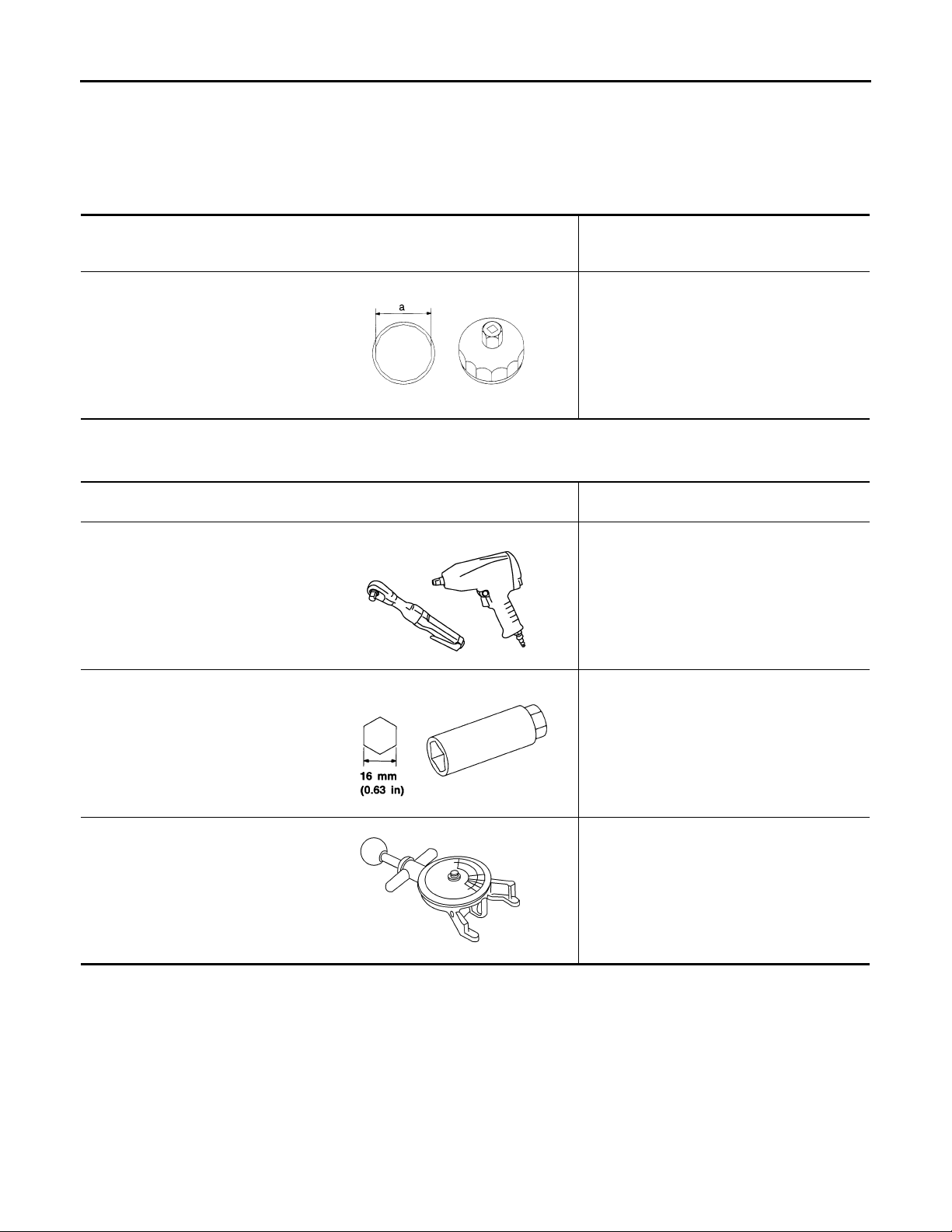
Special Service Tool INFOID:0000000002957328
The actual shapes of Kent-Moore tools may differ from those of special service tools illustrated here.
Tool number
(Kent-Moore No.)
Tool name
KV10115801
(J38956)
Oil filter wrench
S-NT375
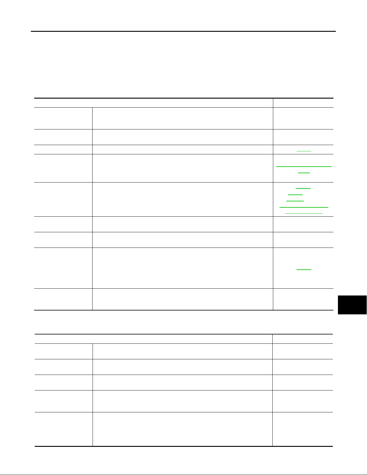
Commercial Service Tool INFOID:0000000002957329
Description
Removing and installing oil filter
a: 64.3 mm (2.531 in)
Tool name
(Kent-Moore No.)
Power tool
(—)
Spark plug wrench
(—)
Belt tension gauge
(BT3373-F)
Description
Loosening nuts and bolts
PBIC0190E
Removing and installing spark plug
S-NT047
Checking drive belt tension (VQ35DE)
AMA126
MA-2
< SERVICE INFORMATION >
Revision: 2009 February 2008 M35/M45
GENERAL MAINTENANCE
GENERAL MAINTENANCE
Explanation of General Maintenance INFOID:0000000002957330
General maintenance includes those items which should be checked during the normal day-to-day operation
of the vehicle. They are essential if the vehicle is to continue operating properly. The owners can perform
checks and inspections themselves or they can have their INFINITI dealers do them.
OUTSIDE THE VEHICLE
The maintenance items listed here should be performed from time to time, unless otherwise specified.
Item Reference page
Tires Check the pressure with a gauge often and always prior to long distance trips.
Adjust the pressure in all tires, including the spare, to the pressure specified.
Check carefully for damage, cuts or excessive wear.
Wheel nuts When checking the tires, make sure no nuts are missing, and check for any
loose nuts. Tighten if necessary.
Tire rotation Tires should be rotated every 12,000 km (7,500 miles). MA-33
Tire Pressure Moni-
toring System (TPMS)
transmitter components
Wheel alignment and
balance
Windshield
Windshield wiper
blades
Doors and engine
hood
Lamps Make sure that the headlamps, stop lamps, tai l lamps, turn signal lamps, and
Replace the TPMS transmitter g rommet seal, valve co re and cap when the tire s
are replaced due to wear or age.
If the vehicle pulls to either side while driving on a straight and level road, or if
you detect uneven or abnormal tire wear, there may be a need for wheel alignment. If the steering wheel or seat vibrates at normal highway speeds, wheel
balancing may be needed.
Clean the windshield on a regular basis. Chec k the windshield at least every six
months for cracks or other damage. Repair as necessary.
Check for cracks or wear if they do not wipe properly. —
Check that all doors and the en gine hood operat e properl y as well as the t runk
lid. Also make sure that all latches lock securely. Lubricate if necessary. Make
sure that the secondary latch keeps the hood from opening when the primary
latch is released.
When driving in areas using road salt or other corrosive materials, check lubrication frequently.
other lamps are all operating properly and installed securely. Also check headlamp aim. Clean the headlamps on a regular basis.
WT-11, "
RSU-5, "
—
—
System Compo-
nent"
MA-31
,
FSU-5
(2WD),
FSU-22
(AWD),
Wheel Align-
ment Inspection"
—
MA-36
—
A
B
C
D
E
F
G
H
I
J
K
MA
INSIDE THE VEHICLE
The maintenance items listed here should be checked on a regular basis, such as when performing periodic maintenance, cleaning the vehicle,
etc.
Item Reference page
Warning lamps and
chimes
Windshield wiper and
washer
Windshield defroster Check that the air comes out of the defroster outlets properly and in sufficient
Steering wheel Check that it has the specifie d play . Check for changes in the steering condi-
Seats Check seat position controls such as seat adjusters, seatback recliner, etc. to
Make sure that all warning lamps and chimes are operating properly. —
Check that the wipers and washer operate pr operly and that the wipe rs do not
streak.
quantity when operating the heater or air conditioner.
tion, such as excessive play, hard steering or strange noises.
Free play: Less than 35 mm (1.38 in )
make sure they operate smoothly an d that all latche s lock securely i n every position. Check that the head restrains move up and down smoothly and that the
locks (if equipped) hold securely in all latched positions. Check that the latches
lock securely for folding-down rear seatbacks.
MA-3
—
—
—
—
M
N
O
P
GENERAL MAINTENANCE
Revision: 2009 February 2008 M35/M45
< SERVICE INFORMATION >
Item Reference page
Seat belts Check that all parts of the seat belt system (e.g. buckles, anchors, adjusters
and retractors) operate properly and smoothly, and are installed securely.
Check the belt webbing for cuts, fraying, wear or damage.
Accelerator pedal Check the pedal for smooth operation and make sure the pedal does not catch
or require uneven effort. Keep the floor mats away from the pedal.
Brakes Check that the brake does not pull the vehicle to one side when applied. —
Brake pedal and
booster
Parking brake Check that the pedal has the proper travel and make sure that the vehicle is
Automatic transmission “Park” mechanism
UNDER THE HOOD AND VEHICLE
The maintenance items listed here should be checked periodically (e.g. each time you check the engine oil or refuel).
Item Reference page
Windshield washer
fluid
Engine coolant level Check the coolant level when the engine is cold. MA-13
Radiator and hoses Check the front of the radiator and clean off any dirt, insects, leaves, etc., that
Brake fluid level Make sure that the brake flu id level is between the “M AX” and “MIN” lines on the
Battery Check the fluid level in each cell. It should be between the “MAX” and “MIN”
Engine drive belts Make sure that no belt is frayed, worn, cracked or oily. MA-11, MA-20
Engine oil level Check the level on the oil level gauge after parking the vehicle on a level spot
Power steering fluid
level and lines
Exhaust system Make sure there are no loose supports, cracks or holes. If the sound of the ex-
Underbody The underbody is frequently exposed to corrosive substances such as those
Fluid leaks Check under the vehicle for fuel, oil, water or other fluid leaks after the vehicle
Check the pedal for smooth ope ration and make sure it ha s the proper distan ce
under it when depressed fully. Check the brake booster function. Be sure to
keep the floor mats away from the pedal.
held securely on a fairly steep hill when only the parking brake is applied.
Check that the lock release button o n the sele ctor lever o perates pro perly an d
smoothly. On a fairly steep hill check that the vehicle is held securely with the
selector lever in the P (Park) position without applying any brakes.
Check that there is adequate fluid in the tank. —
may have accumulated. M ake su re the hoses h ave no cracks, defo rmatio n, deterioration or loose connections.
reservoir.
lines. Vehicles operated in high temperatur es or under severe conditions require frequent checks of the battery fluid level.
and turning off the en gine.
Check the level on the dipstick with the engine off. Check the lines for improper
attachment, leaks, cracks, etc.
haust seems unusual or there is a smell of exhaust fumes, immediately locate
the trouble and correct it.
used on icy roads or to control dust. It is very important to remove these substances, otherwise rust will form on the floor pan, frame, fuel lines and around
the exhaust system. At the end of winter, the underbody should be thoroug hly
flushed with plain water, being careful to clean those areas where mud and di rt
can easily accumulate.
has been parked for a while. Water dripping from the air conditioner after use is
normal. If you should notice any le aks or g asoline fumes are eviden t, check for
the cause and correct it immediately.
MA-37
BR-6
PB-3
MA-33
MA-16
MA-35
MA-27
—
, BR-17
—
, MA-20
—
SC-4
, MA-23
—
—
MA-4

< SERVICE INFORMATION >
Revision: 2009 February 2008 M35/M45
PERIODIC MAINTENANCE
PERIODIC MAINTENANCE
Introduction of Periodic Maintenance INFOID:0000000002957331
Two different maintenance schedules are provided, and should be used, depending upon the conditions in
which the vehicle is mainly operated. After 60,000 miles (96,000 km) or 48 months, continue the periodic
maintenance at the same mileage/time intervals.
Follow Periodic Maintenance Schedule 1 if the driving habits frequently include
one or more of the following driving conditions:
• Repeated short trips of less than 5 miles (8 km).
• Repeated short trips of less than 10 miles (16 km) with outside temperatures
remaining below freezing.
Schedule 1
Schedule 2
• Operating in hot weather in stop-and-go “rush hour” traffic.
• Extensive idling and/or low sp eed driving for long dist ances, such as police, ta xi
or door-to-door delivery use.
• Driving in dusty conditions.
• Driving on rough, muddy, or salt spread roads.
• Towing a trailer, using a camper or a car-top carrier.
Follow Periodic Maintenance Schedule 2 if none of driving conditions shown in
Schedule 1 apply to the driving ha bits.
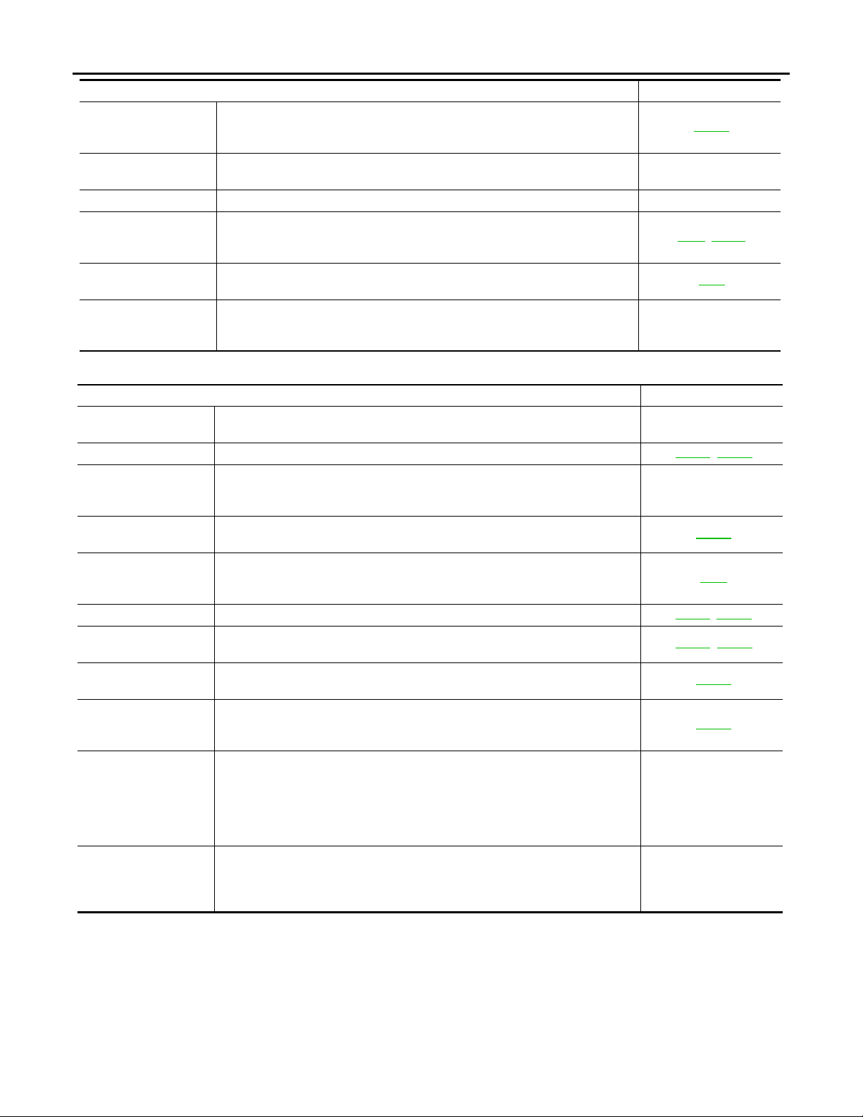
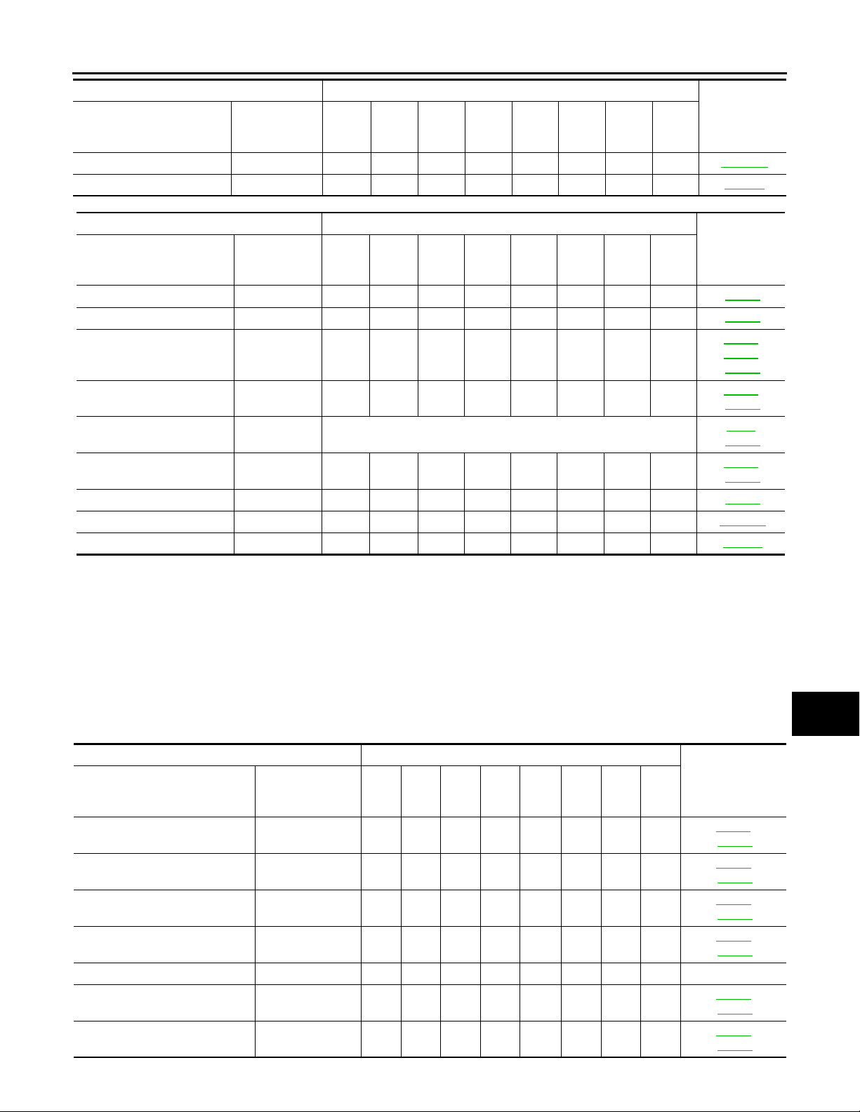
Schedule 1 INFOID:0000000002957332
EMISSION CONTROL SYSTEM MAINTENANCE
Abbreviations: R = Replace. I = Inspect. Correct or replace if necessary. [ ]: At the mileage intervals only
MAINTENANCE OPERATION MAINTENANCE INTERVAL
18.75
Perform at number of miles,
kilometers or months, whichever comes first.
Drive belts NOTE (1)
Air cleaner filter NOTE (2) [R]
EVAP vapor lines I*
Fuel lines I*
Fuel filter NOTE (3) —
Engine coolant NOTE (4)
Engine oil R R R R R R R R
Engine oil filter (Use genuine
NISSAN engine oil filter or
equivalent.)
Spark plugs (Platinum-tipped
type)
Intake & exhaust valve clearance*
Miles x 1,000
(km x 1,000)
Months
NOTE (5)
3.75
(6)
7.50
(12)
3
R RRRRRRR
11.25
(18)
6
Replace every 105,000 miles (169,000 km).
15
12
(30)
15
(24)
9
Emission Control System Maintenance
Chassis and Body
Maintenance
Emission Control System Maintenance
Chassis and Body
Maintenance
26.25
22.5
18
(42)
21
(36)
30
(48)
24
MA-5
MA-5
MA-7
MA-7
Reference
Section -
Page or -
Content Title
MA-11
,
MA-20
,
MA-15
MA-23
,
MA-19
MA-26
,
MA-15
MA-23
,
MA-13
MA-20
,
MA-16
MA-23
MA-17
,
MA-24
MA-18,
MA-25
EM-92
,
EM-222
A
B
C
D
E
F
G
H
I
J
K
MA
M
N
O
P
MA-5
< SERVICE INFORMATION >
Revision: 2009 February 2008 M35/M45
PERIODIC MAINTENANCE
MAINTENANCE OPERATION MAINTENANCE INTERVAL
Perform at number of miles,
kilometers or months, whichever comes first.
Drive belts NOTE (1) I*
Air cleaner filter NOTE (2) [R]
EVAP vapor lines I*
Fuel lines I*
Fuel filter NOTE (3) —
Engine coolant NOTE (4) R*
Engine oil R R R R R R R R
Engine oil filter (Use genuine
NISSAN engine oil filter or
equivalent.)
Spark plugs (Platinum-tipped
type)
Intake & exhaust valve clearance*
NOTE:
(1) After 60,000 miles (96,000 km ) or 48 mont h s, in sp ect e very 15 ,000 mi les (24 , 000 km ) or 12 mo nt hs. Rep lace the dri ve belts if found
damaged or if the auto belt tensioner reading (only for VK45DE engine) reaches the maximum limit.
(2) If operating mainly in dusty conditions, more frequent maintenance may be required.
(3) Maintenance-free item. For servi ce procedures, refer to FL section.
(4) After 60,000 miles (96,000 km) or 48 months, replace every 30,000 miles (48,000 km) or 24 months.
(5) Periodic maintenance is not required. However, if valve noise increases, inspect valve clearance.
* Maintenance items and intervals with “*” are recommen ded by INFINITI for reliable vehicle operation. The owner need not perform
such maintenance in order to maintain the e missio n warran ty or manu factu rer reca ll lia bilit y. Other maintenance items and intervals are
required.
Miles x 1,000
(km x 1,000)
Months
NOTE (5)
33.75
(54)
27
37.5
(60)
R RRRRRRR
41.25
(66)
30
Replace every 105,000 miles (169,000 km).
33
45
(72)
36
48.75
(78)
39
52.5
(84)
42
56.25
(90)
45
60
(96)
48
Reference
Section -
Page or -
Content Title
MA-11
,
MA-20
,
MA-15
MA-23
,
MA-19
MA-26
,
MA-15
MA-23
MA-13,
MA-20
,
MA-16
MA-23
MA-17
,
MA-24
MA-18
,
MA-25
EM-92,
EM-222
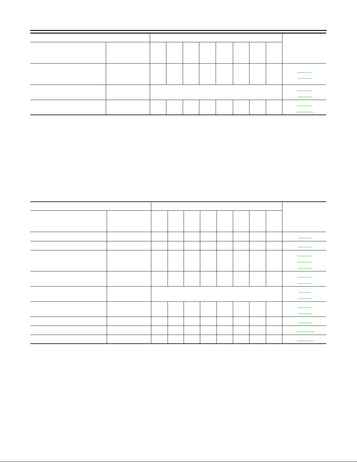
CHASSIS AND BODY MAINTENANCE
Abbreviations: R = Replace. I = Inspect. Correct or replace if necessary.
MAINTENANCE OPERATION MAINTENANCE INTERVAL
30
(48)
24
18
26.25
(42)
21
18.75
Perform at number of miles,
kilometers or months,
whichever comes first.
Brake lines & cables I I MA-33
Brake pads & rotors I I I I MA-34
Automatic transmission &
transfer fluid & differential
gear oil
Steering gear & linkage,
axle & suspension parts
Tire rotation NOTE (2)
Propeller shaft (AWD m od-
els) and drive shaft boots
Exhaust system I I I I MA-27
Miles x 1,000
(km x 1,000)
Months
NOTE (1) I I
3.75
(6)
7.50
(12)
3
11.25
(18)
6
IIII
IIII
9
15
(24)
12
(30)
22.5
(36)
15
MA-6
Reference
Section -
Page or - Con-
tent Title
MA-27,
MA-29
,
MA-30
MA-34,
MA-35
,
MA-3
MA-33
MA-36,
MA-30
< SERVICE INFORMATION >
Revision: 2009 February 2008 M35/M45
PERIODIC MAINTENANCE
MAINTENANCE OPERATION MAINTENANCE INTERVAL
Perform at number of miles,
kilometers or months,
whichever comes first.
In-cabin microfilter R R ATC-120
Climate controlled seat f ilt e r R SE-147
MAINTENANCE OPERAT ION MAINTENANCE INTERVAL
Perform at number of miles,
kilometers or months,
whichever comes first.
Brake lines & cables I I MA-33
Brake pads & rotors I I I I MA-34
Automatic transmission &
transfer fluid & diffe rential
gear oil
Steering gear & linkage,
axle & suspension parts
Tire rotation NOTE (2)
Propeller shaft (AWD mod-
els) and drive shaft boots
Exhaust system I I I I MA-27
In-cabin microfilter R R ATC-120
Climate controlled seat filter R SE-147
NOTE:
(1) If towing a trailer, using a camper or a car-top carrier, or driving on rough or muddy roads, cha nge (not just i nspe ct) flu id (A/T, transfer)/oil at every 30,000 miles (48,000 km) or 24 mo nths. Using automatic transmission flui d other than Genuine NISSAN Matic S
ATF or Matic J AT F will cause deterioration in driveability an d automatic transmission durability, and may damage the automatic transmission, which is not covered by the INFINITI new vehicle limited warranty.
(2) Refer to “Tire rotation” under the “GENERAL MAINTENANCE” heading earlier in this section.
Miles x 1,000
(km x 1,000)
Months
Miles x 1,000
(km x 1,000)
Months
NOTE (1) I I
3.75
(6)
3
33.75
(54)
27
7.50
(12)
37.5
(60)
11.25
(18)
6
30
IIII
IIII
9
41.25
(66)
33
15
(24)
12
45
(72)
36
18.75
(30)
15
48.75
(78)
39
22.5
(36)
18
52.5
(84)
42
26.25
(42)
21
56.25
(90)
45
30
(48)
24
60
(96)
48
Reference
Section -
Page or - Con-
tent Title
Reference
Section - Page
or - Content
Title
MA-27,
MA-29
,
MA-30
MA-34
,
MA-35
,
MA-3
MA-33
MA-36,
MA-30
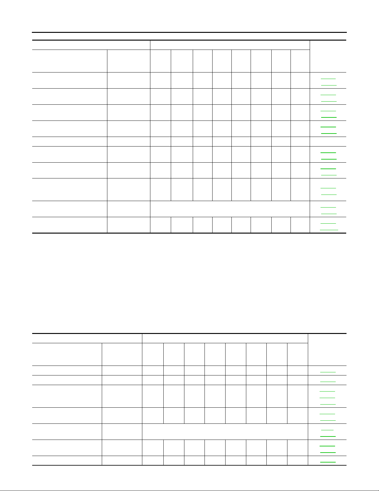
Schedule 2 INFOID:0000000002957333
A
B
C
D
E
F
G
H
I
J
K
EMISSION CONTROL SYSTEM MAINTENANCE
Abbreviations: R = Replace. I = Inspect. Correct or replace if necessary. [ ]: At the mileage intervals only
MAINTENANCE OPERATION MAINTENANCE INTERVAL
52.5
30
45
(72)
36
(84)
42
37.5
18
30
(48)
24
(60)
Perform at number of miles, kilometers or months, whichever
comes first.
Drive belts NOTE (1) I*
Air cleaner filter [R] [R]
EVAP vapor lines I* I*
Fuel lines I* I*
Fuel filter NOTE (2) —
Engine coolant NOTE (3) R*
Engine oil R R R R R R R R
Miles x 1,000
(km x 1,000)
Months
7.5
(12)
6
(24)
12
(36)
22.5
15
60
(96)
48
Reference Sec-
tion - Page or -
Content Title
MA-7
MA-11
MA-20
MA-15
MA-23
MA-19
MA-26
MA-15
MA-23
MA-13
MA-20
MA-16
MA-23
MA
M
,
,
N
O
,
,
,
,
P
< SERVICE INFORMATION >
Revision: 2009 February 2008 M35/M45
PERIODIC MAINTENANCE
MAINTENANCE OPERATION MAINTENANCE INTERVAL
Perform at number of miles, kilometers or months, whichever
comes first.
Engine oil filter (Use genuine
NISSAN engine oil filter or equivalent.)
Spark plugs (Platinum-tipped
type)
Intake & exhaust valve clearance*
NOTE:
(1) After 60,000 miles (96,000 km ) or 48 mont h s, in sp ect e very 15 ,000 mi les (24 , 000 km ) or 12 mo nt hs. Rep lace the dri ve belts if found
damaged or if the auto belt tensioner reading (only for VK45DE engine) reaches the maximum limit.
(2) Maintenance-free item. For servi ce procedures, refer to FL section.
(3) After 60,000 miles (96,000 km) or 48 months, replace every 30,000 miles (48,000 km) or 24 months.
(4) Periodic maintenance is not required. However, if valve noise increases, inspect valve clearance.
* Maintenance items and intervals with “*” are recommen ded by INFINITI for reliable vehicle operation. The owner need not perform
such maintenance in order to maintain the e missio n warran ty or manu factu rer reca ll lia bilit y. Other maintenance items and intervals are
required
Miles x 1,000
(km x 1,000)
Months
NOTE (4)
7.5
15
22.5
(12)
(24)
(36)
6
12
RRRRRRRR
Replace every 105,000 miles (169,000 km).
18
30
(48)
24
37.5
(60)
30
45
(72)
36
52.5
(84)
42
60
(96)
48
Reference Sec-
tion - Page or -
Content Title
MA-17
,
MA-24
MA-18,
MA-25
EM-92,
EM-222
CHASSIS AND BODY MAINTENANCE
Abbreviations: R = Replace. I = Inspect. Correct or replace if necessary.
MAINTENANCE OPERATION MAINTENANCE INTERVAL
52.5
30
45
(72)
36
(84)
42
37.5
18
30
(60)
(48)
24
II
Perform at number of miles, kilometers or months, whichever
comes first.
Brake lines & cables I I I I MA-33
Brake pads & rotors I I I I MA-34
Automatic transmission & transfer fluid & differential gear oil
Steering gear & linkage, axle &
suspension parts
Tire rotation NOTE (2)
Propeller shaft (AWD models)
and drive shaft boots
Exhaust system I I MA-27
In-cabin microfilter R R R R ATC-120
Climate controlled seat filter R R SE-147
NOTE:
(1) Using automatic transmission fluid other than Genuine NISSAN Matic S ATF or Matic J ATF will cause deterioration in drive-
ability and automatic transmission durability, and may damage the automatic transmission, which is not covered by the
INFINITI new vehicle limited warranty.
(2) Refer to “Tire rotation” under the “GENERAL MAINTENANCE” heading earlier in this section.
Miles x 1,000
(km x 1,000)
Months
NOTE (1) IIII
7.5
(12)
6
(36)
(24)
12
IIII
22.5
15
60
(96)
48
Reference Sec-
tion - Page or -
Content Title
,
MA-27
MA-29
,
MA-30
MA-34
,
MA-35
,
MA-3
MA-33
MA-36,
MA-30
MA-8
RECOMMENDED FLUIDS AND LUBRICANTS
Revision: 2009 February 2008 M35/M45
< SERVICE INFORMATION >
RECOMMENDED FLUIDS AND LUBRICANTS
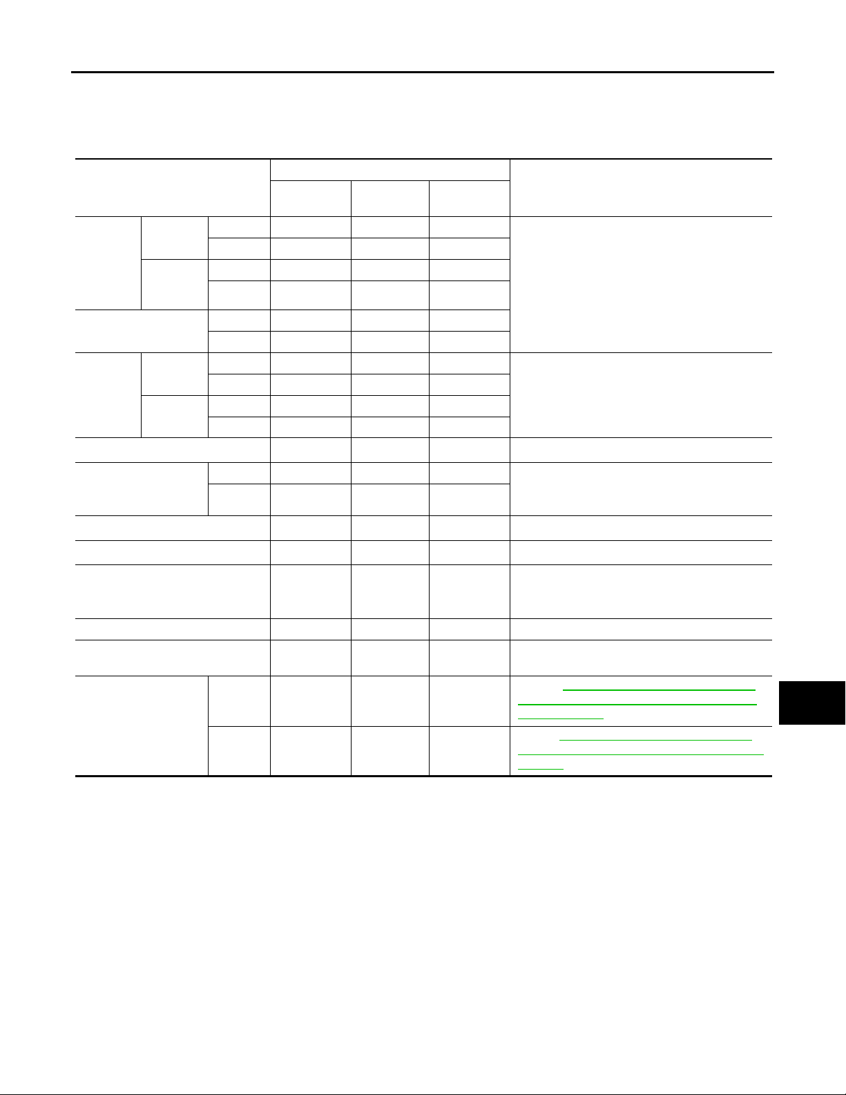
Fluids and Lubricants INFOID:0000000002957334
Capacity (Approximate)
US measure
With oil fil-
Engine oil
Drain and
refill
Dry engine (Overhaul)
Cooling
system
Automatic transmission fluid 10-7/8 qt 9-1/8 qt 10.3
Differential gear oil
Transfer fluid 2-5/8 pt 2-1/4 pt 1.25
Power steering fluid (PSF) 1-1/8 qt 7/8 qt 1.0
Brake fluid — — —
Multi-purpose grease — — — NLGI No. 2 (Lithium soap base)
Windshield washer fluid — — —
Fuel recommendation
*1: For further details, see “Engine Oil Recommendation”.
*2: If Genuine NISSAN Matic S ATF is not available, Genuine NISSAN Matic J ATF may also be used. Using automatic transmission fluid other than genuine NISSAN Matic S ATF or Matic J ATF will cause deterioration in driveability and automatic transmission durability, and may damage the automatic transmission, which is not covered by the INFINITI new veh icle limited
warranty.
*3: For hot climates, viscosity SAE 90 is suitable for ambient temperatures above 0°C (32°F).
*4: If Genuine NISSAN Matic J ATF is not available, Genuine NISSAN Matic D ATF or Canada NISSAN Automatic Transmission Fluid or
equivalent (if available) may also be used.
*5: DEXRON
*6: Available in mainland U.S.A. through an INFINITI dealer.
ter change
Without oil
filter
change
With reservoir tank
Reservoir
tank
TM
VI type ATF or Canada NISSAN Automatic Transmission Fluid may also be used.
VQ35DE 5 qt 4-1/8 qt 4.7
VK45DE 5-3/4 qt 4-7 /8 qt 5.5
VQ35DE 4-5/8 qt 3-7/8 qt 4.4
VK45DE 5-1/8 qt 4-1 /4 qt 4.9
VQ35DE 5-3/4 qt 4-3/4 qt 5.4
VK45DE 7-1/8 qt 5-7 /8 qt 6.7
VQ35DE 9-3/8 qt 7-7/8 qt 8.9
VK45DE 11 qt 9-1/8 qt 10.4
VQ35DE 7/8 qt 3/4 qt 0.8
VK45DE 7/8 qt 3/4 qt 0.8
Front 1-3/8 pt 1-1/8 pt 0.65 Genuine NISSAN Differential Oil Hypoid Super
Rear 3 pt 2-1/2 pt 1.40
VQ35DE———
VK45DE — — —
Imp mea-
sure
Liter
Recommended Fluids/Lubricants
Engine oil with API Certification Mark
Viscosity SAE 5W-30
Genuine NISSAN Long Life Antifreeze/ Coolant
or equivalent
Genuine NISSAN Matic S ATF
GL-5 80W-90 or API GL-5, Viscosity SAE 80W-
*3
90
Genuine NISSAN Matic J ATF
Genuine NISSAN PSF or equivalent
Genuine NISSAN Super Heavy Duty Brake Flu-
*6
id
or equivalent
DOT 3 (US FMVSS No. 116)
Genuine NISSAN Windshield Washer Concentrate Cleaner & Antifreeze or equivalent
Refer to GI-5, "
Premium Gasoline Recommended) (VQ35DE
Engine Models)".
Refer toGI-5, "
Premium Gasoline Required) (VK45DE Engine
Models)".
Precaution for Fuel (Unleaded
Precaution for Fuel (Unleaded
*1
*2
*4
*5
A
B
C
D
E
F
G
H
I
J
K
MA
M
N
O
P
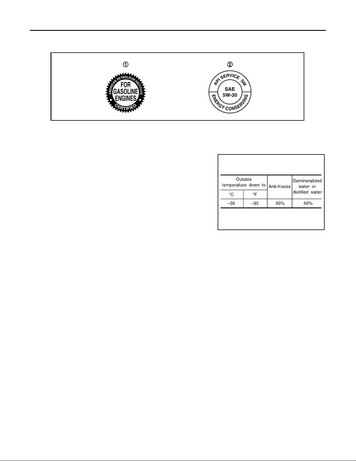
Engine Oil Recommendation INFOID:0000000002957335
NISSAN recommends the use of an energy conserving oil in order to improve fuel economy.
Select only engine oils that meet the American Petroleum Institute (API) certification and International Lubricant Standardization and Approval Committee (ILSAC) certification and SAE viscosity standard. These oils
MA-9
RECOMMENDED FLUIDS AND LUBRICANTS
Revision: 2009 February 2008 M35/M45
< SERVICE INFORMATION >
have the API certification mark on the front of the container. Oils which do not have the specified quality label
should not be used as they could cause engine damage.
SAIA1514E
1. API certification mark 2. API service symbol
Anti-Freeze Coolant Mixture Ratio INFOID:0000000002957336
The engine cooling system is filled at the factory with a high-quality,
year-round, anti-freeze coolant solution. The anti-freeze solution
contains rust and corrosion inhibitors. Therefore, additional cooling
system additives are not necessary.
CAUTION:
When adding or replacing coolant, be sure to use only genuine
NISSAN Long Life Antifreeze/ Coolant or equivalent with the
proper mixture ratio of 50% anti-freeze and 50% demineralized
water/distilled water.
Other types of coolant solutions may damage your cooling system.
SMA947CA
MA-10

ENGINE MAINTENANCE (VQ35DE ENGINE)
Revision: 2009 February 2008 M35/M45
< SERVICE INFORMATION >
ENGINE MAINTENANCE (VQ35DE ENGINE)
Checking Drive Belts INFOID:0000000002957337
WARNING:
Be sure to perform when engine is stopped.
1. Inspect belts for cracks, fraying, wear and oil. If necessary, replace.
2. Inspect drive belt deflection or tension at a point on belt midway
between pulleys.
1 : Power steering oil pump
2 : Alternator
3 : Idler pulley
4 : Crankshaft pulley
5: A/C compressor
• Inspection should be done only when engine is cold, or over
30 minutes after engine is stopped.
• Measure the belt tension with belt tension gauge (Commercial
service tool: BT3373-F or equivalent) (A) at points marked
shown in the figure.
• When measuring the deflection, apply 98 N (10 kg, 22 lb) at
the marked point.
• Adjust if the belt deflection exceeds the limit or if the belt ten-
sion is not within specifications.
CAUTION:
• When checking the belt deflection or the tension immedi-
ately after installation, first adjust it to the specified value.
Then, after turning crankshaft two turns or more, re-adjust
to the specified value to avoid variation in deflection
between pulleys.
• Tighten idler pulley lock nut by hand and measure the deflection or the tension without loose-
ness.
Belt Deflection and Tension
Deflection adjustment Unit: mm (in) Tension adjustment* Unit: N (kg, lb)
Limit
Used belt
After adjust-
(0.28 - 0.31)
(0.35 - 0.39)
ment
7 - 8
9 - 10
New belt
6 - 7
(0.24 - 0.28)
8 - 9
(0.31 - 0.35)
294 (30, 66)
196 (20, 44)
Items
Alternator and power steering oil
pump belt
A/C compressor belt 12 (0.47)
Applied pushing force 98 N (10 kg, 22 lb) —
*: If belt tension gauge cannot be installed at check points shown, check drive be lt tension at different location on belt.
12 (0.47)
Limit
Used belt
After adjust-
ment
730 - 818
(74.5 - 83.4,
164 - 184)
348 - 436
(35.5 - 44.5,
78 - 98)
JPBIA0421ZZ
JPBIA0422ZZ
New belt
838 - 926
(85.5 - 94.5,
188 - 208)
470 - 559
(47.9 - 57.0,
106 - 126)
A
B
C
D
E
F
G
H
I
J
K
MA
M
N
O
Tension Adjustment INFOID:0000000002957338
Portion Belt tightening method for adjustment
Alternator and power steering oil pump belt Adjusting bolt on idler pulley
A/C compressor belt Adjusting bolt on idler pulley
CAUTION:
MA-11
P
ENGINE MAINTENANCE (VQ35DE ENGINE)
Revision: 2009 February 2008 M35/M45
< SERVICE INFORMATION >
• When belt is replaced with a new one, adjust it to value for “New belt” to accommodate for insufficient adaptability with pulley grooves.
• When deflection or tension of belt being used exceeds “Limit”, adjust it to value for “After adjustment”.
• When checking belt deflection or tension immediately after installation, first adjust it to the specified
value. Then, after turning crankshaf t two turns or more, re-adjust to the specified value to avoid variation in deflection between pulleys.
• When installing belt, check that it is correctly engaged with pulley grooves.
• Keep engine oil, working fluid and engine coolant away from belt and pulley grooves.
• Never twist or bend belt excessively.
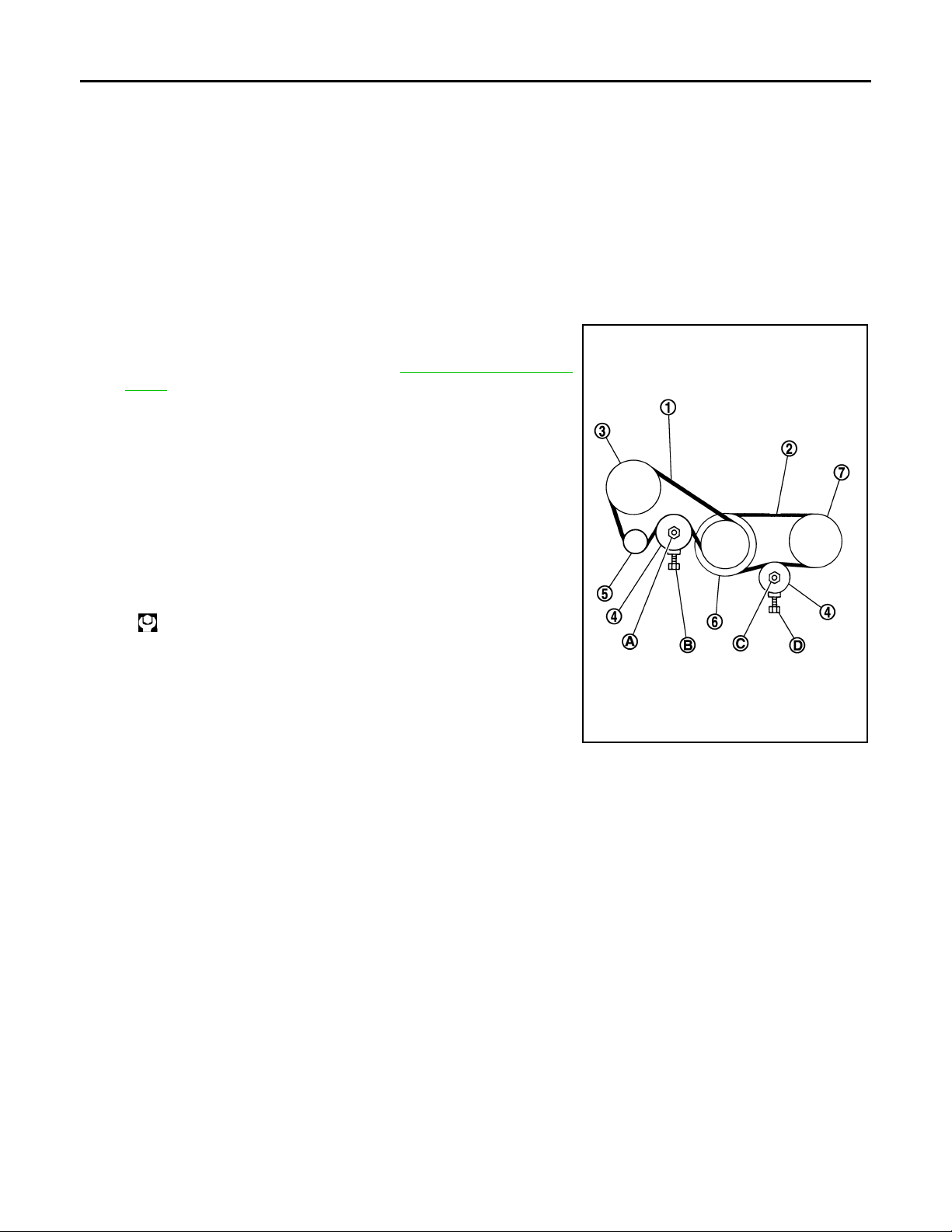
ALTERNATOR AND POWER STEERING OIL PUMP BELT
1. Remove front engine undercover with power tool.
2. Loosen idler pulley lock nut (A) and adjust tension by turning
adjusting bolt (B).
• For the specified belt tension, refer to MA-11, "
Belts".
1 : Alternator and power steering oil pump belt
2: A/C compressor belt
3 : Power steering oil pump
4 : Idler pulley
5: Alternator
6 : Crankshaft pulley
7: A/C compressor
3. Tighten idler pulley lock nut.
Checking Drive
: 34.8 N·m (3.5 kg-m, 26 ft-lb)
A/C COMPRESSOR BELT
1. Remove front engine undercover with power tool.
JPBIA0423ZZ
MA-12

ENGINE MAINTENANCE (VQ35DE ENGINE)
Revision: 2009 February 2008 M35/M45
< SERVICE INFORMATION >
2. Loosen idler pulley lock nut (C) and adjust tension by turning
adjusting bolt (D).
• For the specified belt tension, refer to MA-11, "
Belts".
3. Tighten idler pulley lock nut.
: 34.8 N·m (3.5 kg-m, 26 ft-lb)
Checking Drive
A
B
C
D
E
F
JPBIA0423ZZ
Changing Engine Coolant INFOID:0000000002957339
WARNING:
• To avoid being scalded, never change engine coolant when the engine is hot.
• Wrap a thick cloth around radiator cap and carefully remove radiator cap. First, turn radiator cap a
quarter of a turn to release built-up pressure. Then turn radiator cap all the way.
• Be careful not to allow engine coolant to contact drive belts.
DRAINING ENGINE COOLANT
1. Remove engine room cover (RH and LH). Refer to EM-14.
2. Remove air duct (inlet). Refer to EM-18
3. Open radiator drain plug at the bottom of radiator, and then
remove radiator cap.
1 : Radiator drain plug hole
2 : Front engine under cover
: Engine front
.
PBIC3395E
G
H
I
J
K
MA
M
N
When draining all of engine coolant in the system, open water drain plugs on cylinder block. Refer
to EM-124, "
Disassembly and Assembly".
4. Remove reservoir tank as necessary, and drain engine coolant and clean reservoir tank before installing.
5. Check drained engine coolant for contaminants such as rust, corrosion or discoloration.
If contaminated, flush the engine cooling system. Refer to CO-10, "
Changing Engine Coolant".
REFILLING ENGINE COOLANT
1. Install reservoir tank if removed, and radiator drain plug.
CAUTION:
Be sure to clean drain plug and install with new O-ring.
MA-13
O
P

ENGINE MAINTENANCE (VQ35DE ENGINE)
Revision: 2009 February 2008 M35/M45
< SERVICE INFORMATION >
Radiator drain plug:
: 1.2 N·m (0.12 kg-m, 11 in-lb)
If water drain plugs on cylinder block are removed, close and tighten them. Refer to EM-124, "Dis-
assembly and Assembly".
2. Check that each hose clamp has been firmly tightened.
3. Remove air relief plug on heater hose.
4. Fill radiator, and reservoir tank if removed, to specified level.
• Pour engine coolant through engine coolant filler neck
slowly of less than 2 (2-1/8 US qt, 1-3/4 lmp qt) a minute
to allow air in system to escape.
• Use Genuine NISSAN Long Life Antifreeze/Coolant or
equivalent mixed with water (distilled or demineralized).
Refer to MA-9
.
SBIA0445E
Engine coolant capacity
(With reservoir tank at “MAX” level)
: Approximately 8.9 (9-3/8 US qt, 7-7/8 lmp qt)
SMA182B
Reservoir tank engine coolant capacity
(At “MAX” level)
: 0.8 (7/8 US qt, 3/4 lmp qt)
• When engine coolant overflows air relief hole on heater hose,
install air relief plug with new O-ring.
Air relief plug:
: 1.2 N·m (0.12 kg-m, 11 ft-lb)
SMA412B
5. Install radiator cap.
6. Warm up engine until opening thermostat. Standard for warming-up time is approximately 10 minutes at
3,000 rpm.
• Check thermostat opening condition by touching radiator hose (lower) to see a flow of warm water.
CAUTION:
Watch water temperature gauge so as not to overheat engine.
7. Stop the engine and cool down to less than approximately 50°C (122°F).
• Cool down using fan to reduce the time.
• If necessary, refill radiator up to filler neck with engine coolant.
8. Refill reservoir tank to “MAX” level line with engine coolant.
9. Repeat steps 4 through 7 two or more times with radiator cap installed until engine coolant level no l onger
drops.
10. Check cooling system for leaks with engine running.
11. Warm up the engine, and check for sound of engine coolant flow while running engine from idle up to
3,000 rpm with heater temperature controller set at several position between “COOL” and “WARM”.
MA-14

ENGINE MAINTENANCE (VQ35DE ENGINE)
Revision: 2009 February 2008 M35/M45
< SERVICE INFORMATION >
• Sound may be noticeable at heater unit.
12. Repeat step 11 three times.
13. If sound is heard, bleed air from cooling system by repeating step 4 through 7 until engine coolant level no
longer drops.
FLUSHING COOLING SYSTEM
1. Install reservoir tank if removed, and radiator drain plug.
CAUTION:
Be sure to clean drain plug and install with new O-ring.
A
B
C
Radiator drain plug:
: 1.2 N·m (0.12 kg-m, 11 in-lb)
If water drain plugs on cylinder block are removed, close and tighten them. Refer to EM-124, "
Dis-
assembly and Assembly".
2. Remove air relief plug on heater hose.
SBIA0445E
3. Fill radiator with water until water spills from the air relief hole, then close air relief plug. Fill radiator and
reservoir tank with water and reinstall radiator cap.
Air relief plug:
: 1.2 N·m (0.12 kg-m, 11 ft-lb)
4. Run the engine and warm it up to normal operating temperature.
5. Rev the engine two or three times under no-load.
6. Stop the engine and wait until it cools down.
7. Drain water from the system. Refer to CO-10, "
Changing Engine Coolant".
8. Repeat steps 1 through 7 until clear water begins to drain from radiator.
D
E
F
G
H
I
J
K
MA
Checking Fuel Line INFOID:0000000002957340
Inspect fuel lines, filler cap and tank for improper attachment, leaks,
cracks, damage, loose connections, chafing or deterioration.
If necessary, repair or replace damaged parts.
Changing Air Cleaner Filter INFOID:0000000002957341
VISCOUS PAPER TYPE
The viscous paper type filter does not need cleaning between replacement intervals. Refer to MA-5.
MA-15
M
N
O
P
SMA803A

ENGINE MAINTENANCE (VQ35DE ENGINE)
Revision: 2009 February 2008 M35/M45
< SERVICE INFORMATION >
Changing Engine Oil
INFOID:0000000002957342
WARNING:
• Be careful not to burn yourself, as engine oil may be hot.
• Prolonged and repeated contact with used engine oil may cause skin cancer. Try to avoid direct skin
contact with used engine oil. If skin contact is made, wash thoroughly with soap or hand cleaner as
soon as possible.
1. Warm up the engine, and check for engine oil leakage from engine components. Refer to LU-5, "
Inspec-
tion".
2. Stop the engine and wait for 10 minutes.
3. Loosen oil filler cap.
4. Remove mounting bolts, and then pull down the rear of front
engine under cover (1) and secure it using clip.
5. Remove drain plug (2) and then drain engine oil.
KBIA3593J
6. Install drain plug with new washer . Refer to EM-30
.
CAUTION:
Be sure to clean drain plug and install with new washer.
Oil pan drain plug:
: 34.3 N·m (3.5 kg-m, 25 ft-lb)
7. Refill with new engine oil.
Engine oil specification and viscosity:
Refer to MA-9
Engine oil capacity (Approximate):
Drain and refill
Dry engine (Overhaul) 5.4 (5-3/4, 4-3/4)
.
Unit: (US qt, lmp qt)
With oil filter change 4.7 (5, 4-1/8)
Without oil filter change 4.4 (4-5/8, 3-7/8)
CAUTION:
• When filling engine oil, never pull out oil level gauge.
• The refill capacity depends on the engine oil temperature and drain time. Use these specifications for reference only.
• Always use oil level gauge to determine the proper amount of engine oil in engine.
8. Warm up the engine and check area around drain plug and oil filter for engine oil leakage.
9. Stop the engine and wait for 10 minutes.
10. Check the engine oil level.
MA-16
PBIC0249E

ENGINE MAINTENANCE (VQ35DE ENGINE)
Revision: 2009 February 2008 M35/M45
< SERVICE INFORMATION >
Changing Oil Filter INFOID:0000000002957343
REMOVAL
WARNING:
Be careful not to get burned when the engine and engine oil may be hot.
1. Remove front engine undercover with power tool.
2. Using oil filter wrench (SST), remove oil filter.
CAUTION:
• Oil filter is provided with relief valve. Use Genuine NISSAN engine oil filter or equivalent.
• When removing, prepare a shop cloth to absorb any
engine oil leakage or spillage.
• Never allow engine oil to adhere to drive belts.
• Completely wipe off any engine oil that adheres to engine
and vehicle.
A
B
C
D
E
INSTALLATION
1. Remove foreign materials adhering to oil filter installation surface.
2. Apply engine oil to the oil seal contact surface of new oil filter.
SBIA0454E
SBIA0455E
F
G
H
I
J
K
MA
M
3. Screw oil filter manually until it touches the installation surface,
then tighten it by 2/3 turn. Or tighten to the specification.
Oil filter:
: 17.7 N·m (1.8 kg-m, 13 ft-lb)
INSPECTION AFTER INSTALLATION
1. Check the engine oil level. Refer to MA-16, "Changing Engine Oil".
MA-17
SMA010
N
O
P
SMA229B

ENGINE MAINTENANCE (VQ35DE ENGINE)
Revision: 2009 February 2008 M35/M45
< SERVICE INFORMATION >
2. Start the engine, and check there is no leak of engine oil.
3. Stop the engine and wait for 10 minutes.
4. Check the engine oil level, and adjust the level. Refer to MA-16, "
Changing Engine Oil".
Changing Spark Plugs (Platinum-Tipped Type) INFOID:0000000002957344
REMOVAL
1. Remove engine cover with power tool. Refer to EM-20.
2. Remove ignition coil. Refer to EM-43
3. Remove spark plug with a spark plug wrench (commercial service tool).
CAUTION:
Never drop or shock spark plug.
INSPECTION AFTER REMOVAL
Use the standard type spark plug for normal condition.
The hot type spark plug is suitable when fouling occurs with the standard type spark plug under conditions
such as:
• Frequent engine starts
• Low ambient temperatures
The cold type spark plug is suitable when spark knock occurs with the standard type spark plug under conditions such as:
• Extended highway driving
• Frequent high engine revolution
.
SEM294A
Make NGK
Standard type PLFR5A-11
Hot type PLFR4A-11
Cold type PLFR6A-11
Gap (Nominal) : 1.1 mm (0.043 in)
CAUTION:
• Never drop or shock spark plug.
• Never use a wire brush for cleaning.
• If plug tip is covered with carbon, spark plug cleaner may be
used.
Cleaner air pressure:
2
Less than 588 kPa (6 kg/cm
, 85 psi)
Cleaning time:
Less than 20 seconds
SMA773C
MA-18

ENGINE MAINTENANCE (VQ35DE ENGINE)
Revision: 2009 February 2008 M35/M45
< SERVICE INFORMATION >
• Checking and adjusting plug gap is not required between
change intervals.
INSTALLATION
Install in the reverse order of removal.
A
B
C
SMA806CA
D
: 24.5 N·m (2.5 kg-m, 18 ft-lb)
Checking EVAP Vapor Line INFOID:0000000002957345
1. Visually inspect EVAP vapor lines for improper attachment and for cracks, damage, loose connections,
chafing and deterioration.
2. Inspect fuel tank filler cap vacuum relief valve for clogging, sticking, etc.
Refer to EC-40
.
E
F
G
H
I
J
K
MA
MA-19
M
N
O
P

ENGINE MAINTENANCE (VK45DE ENGINE)
Revision: 2009 February 2008 M35/M45
< SERVICE INFORMATION >
ENGINE MAINTENANCE (VK45DE ENGINE)
Checking Drive Belts INFOID:0000000002957346
PBIC3822E
WARNING:
Be sure to perform when the engine is stopped.
• Remove air duct (inlet) when inspecting drive belt for alternator, water pump and A/C compressor.
• Remove front engine undercover with power tool when inspecting power steering oil pump belt.
• Check that indicator (single line notch) of each auto tensioner is within the allowable working range
(between three line notches).
NOTE:
• Check auto tensioner indication when engine is cold.
• When new drive belt is installed, the range should be “A”.
• The indicator notch is located on the moving side of the tensioner for alternator , water pump and A/C com-
pressor belt, while it is found on the fixed side for power steering oil pump belt.
• Visually check entire belt for wear, damage or cracks.
• If the indicator is out of allowable working range or belt is damaged, replace belt.
Tension Adjustment INFOID:0000000002957347
Belt tensioning is not necessary, as it is automatically adjusted by auto tensioner.
Changing Engine Coolant INFOID:0000000002957348
WARNING:
• To avoid being scalded, never change engine coolant when engine is hot.
• Wrap a thick cloth around radiator cap and carefully remove radiator cap. First, turn radiator cap a
quarter of a turn to release built-up pressure. Then turn radiator cap all the way.
• Be careful not to allow engine coolant to contact drive belts.
DRAINING ENGINE COOLANT
1. Remove engine room cover (RH and LH). Refer to EM-171.
2. Remove engine cover with power tool. Refer to EM-177
.
MA-20

ENGINE MAINTENANCE (VK45DE ENGINE)
Revision: 2009 February 2008 M35/M45
< SERVICE INFORMATION >
3. Open radiator drain plug at the bottom of radiator, and then
remove radiator cap.
1 : Radiator drain plug hole
2 : Front engine undercover
: Engine front
PBIC3395E
When draining all of engine coolant in the system, open water drain plugs on cylinder block. Refer
to EM-250, "
4. Remove reservoir tank as necessary, and drain engine coolant and clean reservoir tank before installing.
5. Check drained engine coolant for contaminants such as rust, corrosion or discoloration.
If contaminated, flush the engine cooling system. Refer to "FLUSHING COOLING SYSTEM".
REFILLING ENGINE COOLANT
1. Install reservoir tank if removed, and radiator drain plug.
CAUTION:
Be sure to clean radiator drain plug and install with new O-ri ng.
Disassembly and Assembly".
A
B
C
D
E
F
G
Radiator drain plug:
: 1.2 N·m (0.12 kg-m, 11 in-lb)
If water drain plugs on cylinder block are removed, close and tighten them. Refer to EM-250, "
assembly and Assembly".
2. Check that each hose clamp has been firmly tightened.
3. Remove air relief plug (1) on heater hose.
: Engine front
4. Fill thermostat housing and reservoir tank to specified level.
• Refill engine coolant up to filler neck of thermostat housing.
• Pour engine coolant through engine coolant filler neck slowly of less than 2 (2-1/8 US qt, 1-3/4
Imp qt) a minute to allow air in system to escape.
• Use Genuine NISSAN Long Life Antifreeze/Coolant or equivalent mixed with water (distilled or
demineralized). Refer to MA-9
.
H
Dis-
I
J
K
MA
PBIC3394E
M
N
Engine coolant capacity
(With reservoir tank at “MAX” level):
Approx. 10.4 (11 US qt, 9-1/8 Imp qt)
MA-21
O
P

ENGINE MAINTENANCE (VK45DE ENGINE)
Revision: 2009 February 2008 M35/M45
< SERVICE INFORMATION >
Reservoir tank engine coolant capacity
(At “MAX” level):
0.8 (7/8 US qt, 3/4 lmp qt)
• When engine coolant overflows air relief hole on heater hose,
install air relief plug.
Air relief plug:
: 1.2 N·m (0.12 kg-m, 11 in-lb)
SMA412B
5. Install radiator cap.
6. Warm up until opening thermostat. Standard for warming-up time is approximately 10 minutes at 3,000
rpm.
• Check thermostat opening condition by touching radiator hose (lower) to see a flow of warm water.
CAUTION:
Watch water temperature gauge so as not to overheat engine.
7. Stop engine and cool down to less than approximately 50°C (122°F).
• Cool down using a fan to reduce the time.
• If necessary, refill engine coolant up to filler neck of thermostat housing.
8. Refill reservoir tank to “MAX” level line with engine coolant.
9. Repeat steps 4 through 7 two or more times with radiator cap installed until engine coolant level no l onger
drops.
10. Check cooling system for leaks with engine running.
11. Warm up engine, and check for sound of engine coolant flow while running engine from idle up to 3,000
rpm with heater temperature controller set at several position between “COOL” and “WARM”.
• Sound may be noticeable at heater unit.
12. Repeat step 11 three times.
13. If sound is heard, bleed air from cooling system by repeating steps 4 through 7 until engine coolant level
no longer drops.
FLUSHING COOLING SYSTEM
1. Install reservoir tank, and radiator drain plug.
CAUTION:
Be sure to clean drain plug and install with new O-ring.
Radiator drain plug:
: 1.2 N·m (0.12 kg-m, 11 in-lb)
If water drain plugs on cylinder block are removed, close and tighten them. Refer to EM-250, "Dis-
assembly and Assembly".
2. Remove air relief plug (1) on heater hose.
: Engine front
PBIC3394E
3. Fill thermostat housing with water until water spills from the air relief hole, then close air relief plug. Fill
thermostat housing and reservoir tank with water and reinstall radiator cap.
MA-22

ENGINE MAINTENANCE (VK45DE ENGINE)
Revision: 2009 February 2008 M35/M45
< SERVICE INFORMATION >
Air relief plug:
: 1.2 N·m (0.12 kg-m, 11 in-lb)
4. Run engine and warm it up to normal operating temperature.
5. Rev engine two or three times under no-load.
6. Stop engine and wait until it cools down.
7. Drain water from the system. Refer to CO-38, "
Changing Engine Coolant".
8. Repeat steps 1 through 7 until clear water begins to drain from radiator.
Checking Fuel Line INFOID:0000000002957349
Inspect fuel lines, fuel filler cap and fuel tank for improper attachment, leaks, cracks, damage, loose connections, chafing or deterioration.
If necessary, repair or replace damaged parts.
SMA803A
Changing Air Cleaner Filter INFOID:0000000002957350
A
B
C
D
E
F
G
H
VISCOUS PAPER TYPE
The viscous paper type filter does not need cleaning between replacement intervals. Refer to MA-5.
Changing Engine Oil INFOID:0000000002957351
WARNING:
• Be careful not to burn yourself, as engine oil may be hot.
• Prolonged and repeated contact with used engine oil may cause skin cancer. Try to avoid direct skin
contact with used engine oil. If skin contact is made, wash thoroughly with soap or hand cleaner as
soon as possible.
1. Warm up engine, put vehicle horizontally and check for engine oil leakage from engine components. Refer
to LU-23, "
2. Stop engine and wait for 15 minutes.
3. Loosen oil filler cap.
4. Remove mounting bolts, and then pull down the rear of front engine undercover and secure it using clip.
5. Remove drain plug and then drain engine oil.
6. Install drain plug with new washer. Refer to EM-185
CAUTION:
Be sure to clean drain plug and install with new washer.
Inspection".
PBIC0993E
.
I
J
K
MA
M
N
O
P
MA-23

ENGINE MAINTENANCE (VK45DE ENGINE)
Revision: 2009 February 2008 M35/M45
< SERVICE INFORMATION >
Oil pan drain plug:
: 34.3 N·m (3.5 kg-m, 25 ft-lb)
7. Refill with new engine oil.
Engine oil specification and viscosity:
Refer to MA-9
Engine oil capacity (Approximate):
Unit: (US qt, Imp qt)
Drain and refill
Dry engine (engine overhaul) 6.7 (7-1/8, 5-7/8)
CAUTION:
• The refill capacity depends on the engine oil temperature and drain time. Use these specifications for reference only.
• Always use oil level gauge to determine the proper amount of engine oil in the engine.
8. Warm up engine and check area around drain plug and oil filter for oil leakage.
9. Stop engine and wait for 15 minutes.
10. Check the engine oil level.
.
With oil filter change 5.5 (5-3/4, 4-7/8)
without oil filter change 4.9 (5-1/8, 4-1/4)
PBIC0801E
Changing Oil Filter INFOID:0000000002957352
REMOVAL
WARNING:
Be careful not to get burned when the engine and engine oil may be hot.
1. Remove front engine undercover with power tool.
2. Using the oil filter wrench (SST), remove the oil filter.
CAUTION:
• Oil filter is provided with relief valve. Use Genuine NISSAN engine oil filter or equivalent.
• When removing, prepare a shop cloth to absorb any
engine oil leakage or spillage.
• Never allow engine oil to adhere to drive belts.
• Completely wipe off any engine oil that adhere to engine
and vehicle.
PBIC1525E
INSTALLATION
1. Remove foreign materials adhering to oil filter installation surface.
MA-24

ENGINE MAINTENANCE (VK45DE ENGINE)
Revision: 2009 February 2008 M35/M45
< SERVICE INFORMATION >
2. Apply new engine oil to the oil seal circumference of the new oil
filter.
3. Screw oil filter manually until it touches the installation surface,
then tighten it by 2/3 turn. Or tighten to specification.
Oil filter:
: 17.7 N·m (1.8 kg-m, 13 ft-lb)
A
B
C
SMA010
D
E
F
G
SMA229B
INSPECTION AFTER INSTALLATION
1. Check the engine oil level. Refer to MA-23, "Changing Engine Oil".
2. Start engine, and check there is no leaks of engine oil.
3. Stop engine and wait for 15 minutes.
4. Check the engine oil level and add engine oil. Refer to MA-23, "
Changing Engine Oil".
Changing Spark Plugs (Platinum-Tipped Type) INFOID:0000000002957353
REMOVAL
1. Remove engine cover with power tool. Refer to EM-171.
2. Remove ignition coil. Refer to EM-189
3. Remove spark plug with spark plug wrench (commercial service
tool).
CAUTION:
Never drop or shock spark plug.
INSPECTION AFTER REMOVAL
Use standard type spark plug for normal condition.
.
SEM294A
H
I
J
K
MA
M
N
O
Hot type spark plug is suitable when fouling occurs with standard type spark plug under conditions such as:
• Frequent engine starts
• Low ambient temperatures
Cold type spark plug is suitable when spark plug knock occurs with standard type spark plug under conditions such as:
• Extended highway driving
• Frequent high engine revolution
MA-25
P

ENGINE MAINTENANCE (VK45DE ENGINE)
Revision: 2009 February 2008 M35/M45
< SERVICE INFORMATION >
Make NGK
Stan dard type PLFR5A-11
Hot type PLFR4A-11
Cold type PLFR6A-11
Gap (Nominal) : 1.1 mm (0.043 in)
CAUTION:
• Never drop or shock spark plug.
• Never use wire brush for cleaning.
• If plug tip is covered with carbon, spark plug cleaner may be
used.
Cleaner air pressure:
Less than 588 kPa (6 kg/cm
Cleaning time:
Less than 20 seconds
2
, 85 psi)
SMA773C
• Checking and adjusting plug gap is not required between
change intervals.
SMA806CA
INSTALLATION
Install in the reverse order of removal.
Spark plug:
: 24.5 N·m (2.5 kg-m, 18 ft-lb)
Checking EVAP Vapor Line INFOID:0000000002957354
1. Visually inspect EVAP vapor lines for improper attachment and for cracks, damage, loose connections,
chafing and deterioration.
2. Inspect fuel tank filler cap vacuum relief valve for clogging, sticking, etc.
Refer to EC-662
.
MA-26

CHASSIS AND BODY MAINTENANCE
Revision: 2009 February 2008 M35/M45
< SERVICE INFORMATION >
CHASSIS AND BODY MAINTENANCE
Checking Exhaust System INFOID:0000000002957355
Check exhaust pipes, muffler and mounting for improper attachment,
leaks, cracks, damage, chafing or deterioration.
• If anything is found, repair or replace damaged parts.
SMA211A
Checking A/T Fluid INFOID:0000000002957356
1. Warm up engine.
2. Check for A/T fluid leakage.
3. Loosen the level gauge bolt.
4. Before driving, A/T fluid level can be checked at A/T fluid temperatures of 30 to 50°C (86 to 122°F) using “COLD” range on A/
T fluid level gauge as follows.
a. Park vehicle on level surface and set parking brake.
b. Start engine and move selector lever through each gear posi-
tion. Leave selector lever in “P” position.
c. Check A/T fluid level with engine idling.
d. Remove A/T fluid level gauge and wipe clean with lint-free
paper.
CAUTION:
When wiping away the A/T fluid level gauge, always use
lint-free paper, not a cloth one.
e. Re-insert A/T fluid level gauge into A/T fluid charging pipe as far as it will go.
CAUTION:
To check A/T fluid level, insert the A/T fluid level gauge until the cap contacts the end of the A/T
fluid charging pipe, with the A/T fluid level gauge reversed from the normal attachment conditions.
f. Remove A/T fluid level gauge and note reading. If reading is at low side of range, add ATF to the A/T fluid
charging pipe.
CAUTION:
Do not overfill.
5. Drive vehicle for approximately 5 minutes in urban areas.
6. Make the A/T fluid temperature approximately 65°C (149°F).
NOTE:
SCIA4835E
A
B
C
D
E
F
G
H
I
J
K
MA
M
N
MA-27
O
P

CHASSIS AND BODY MAINTENANCE
Revision: 2009 February 2008 M35/M45
< SERVICE INFORMATION >
A/T fluid level will be greatly affected by temperature as shown in figure. Therefore, be certain to
perform operation while checking data with CONSULT-III.
SLIA0016E
a. Select “DATA MONITOR”.
b. Read out the value of “A TF TEMP 1”.
7. Re-check A/T fluid level at A/T fluid temperatures of approximately 65°C (149°F) using “HOT” range on A/
T fluid level gauge.
CAUTION:
• When wiping away the A/T fluid level gauge, always use lint-free paper, not a cloth one.
• To check A/T fluid level, insert the A/T fluid level gauge
until the cap contacts the end of the A/T fluid charging
pipe, with the A/T fluid level gauge reversed from the normal attachment conditions as shown.
8. Check A/T fluid condition.
• If ATF is very dark or smells burned, check operation of A/T.
Flush cooling system after repair of A/T.
• If A/T fluid contains frictional material (clutches, bands, etc.),
replace radiator and flush cooler line using cleaning solvent
and compressed air after repair of A/T. Refer to CO-13
VQ35DE engine), CO-41
(for VK45DE engine) and AT-14, "A/
T Fluid Cooler Cleaning".
9. Install the removed A/T fluid level gauge in the A/T fluid charging
pipe.
10. Tighten level gauge bolt.
(for
SCIA2899E
Level gauge bolt
: 5.1 N·m (0.52 kg-m, 45 in-lb)
Changing A/T Fluid INFOID:0000000002957357
1. Warm up ATF.
2. Stop engine.
MA-28
SCIA4896E

CHASSIS AND BODY MAINTENANCE
Revision: 2009 February 2008 M35/M45
< SERVICE INFORMATION >
3. Loosen the level gauge bolt.
4. Drain ATF from drain plug and refill with new ATF. Always refill
same volume with drained A T F.
• To replace the ATF, pour in new ATF at the A/T fluid charging
pipe with the engine idling and at the same time drain the old
ATF from the radiator cooler hose return side.
• When the color of the ATF coming out is about the same as
the color of the new ATF, the replacement is complete. The
amount of new ATF to use should be 30 to 50% increase of
the stipulated amount.
ATF: Genuine NISSAN Matic S ATF
Fluid capacity:
10.3 (10-7/8 US qt, 9-1/8 lmp qt)
A
B
C
SCIA4896E
D
CAUTION:
• Use Genuine NISSAN Matic S ATF.
• If Genuine NISSAN Matic S ATF is not available, Genuine NISSAN Matic J ATF may also be used.
Using ATF other than Genuine NISSAN Matic S ATF or Matic J ATF will cause deterioration in
driveability and automatic transmission durability, and may damage the automatic transmission,
which is not covered by the INFINITI new vehicle limited warranty.
• When filling ATF, take care not to scatter heat generating parts such as exhaust.
• Do not reuse drain plug gasket.
Drain plug
: 34 N·m (3.5 kg-m, 25 ft-lb)
5. Run engine at idle speed for 5 minutes.
6. Check A/T fluid level and condition. Refer to AT-12, "
Checking A/T Fluid". If A TF is still dirty, repeat step 2.
through 5.
7. Install the removed A/T fluid level gauge into A/T fluid charging pipe.
8. Tighten the level gauge bolt.
Level gauge bolt
: 5.1 N·m (0.52 kg-m, 45 in-lb)
Checking Transfer Fluid INFOID:0000000002957358
Check for fluid leakage and fluid level.
(For details, refer to TF-10, "
CAUTION:
Never start engine while checking fluid level.
Inspection".)
E
F
G
H
I
J
K
MA
M
Filler plug:
: 35 N·m (3.6 kg-m, 26 ft-lb)
Changing Transfer Fluid INFOID:0000000002957359
CAUTION:
When draining fluid, protect exhaust tube flange with cover.
1. Drain fluid from drain plug and refill with new gear fluid.
(For details, refer to TF-10, "
Replacement".)
MA-29
SDIA2028E
N
O
P

CHASSIS AND BODY MAINTENANCE
Revision: 2009 February 2008 M35/M45
< SERVICE INFORMATION >
2. Check fluid level.
CAUTION:
Carefully fill the fluid. (Fill up for Approx. 3 minutes.)
Fluid grade:
Genuine NISSAN Matic J ATF
Refer to MA-9
.
Fluid capacity:
: Approx. 1.25 (2-5/8 US pt, 2-1/4 lmp pt)
Drain plug:
SDIA2087E
: 29.4 N·m (3.0 kg-m, 22 ft-lb)
Filler plug:
: 35 N·m (3.6 kg-m, 26 ft-lb)
Checking Propeller Shaft INFOID:0000000002957360
Check propeller shaft for damage, looseness or grease leakage.
Tightening torque:
Refer to PR-7
SMA118A
Checking Differential Gear Oil INFOID:0000000002957361
Check for oil leakage.
(For details, refer to FFD-9, "
RFD-9, "
Checking Differential Gear Oil".)
Checking Differential Gear Oil" and
SMA012C
Changing Differential Gear Oil INFOID:0000000002957362
1. Drain oil from drain plug and refill with new gear oil.
(For details, refer to FFD-9, "
Changing Differential Gear Oil" and RFD-9, "Changing Differential Gear Oil ".)
MA-30

CHASSIS AND BODY MAINTENANCE
Revision: 2009 February 2008 M35/M45
< SERVICE INFORMATION >
2. Check oil level.
Oil grade and Viscosity:
Refer to MA-9
Capacity:
Front final drive (F160A)
0.65 (1 - 3/8 US pt, 1 - 1/8 lmp pt)
Rear final drive (R200)
1.4 (3 US pt, 2 - 1/2 lmp pt)
Filler plug:
Front final drive
.
A
B
C
SDIA1151E
D
: 34.5 N-m (3.5 kg-m, 25 ft-lb)
Rear final drive
: 34.5 N-m (3.5 kg-m, 25 ft-lb)
Drain plug:
Front final drive
: 34.5 N-m (3.5 kg-m, 25 ft-lb)
Rear final drive
: 34.5 N-m (3.5 kg-m, 25 ft-lb)
Balancing Wheels (Bonding Weight Type) INFOID:0000000002957363
REMOVAL
1. Remove inner and outer balance weights from the road wheel.
CAUTION:
Be careful not to scratch the road wheel during removal.
2. Using releasing agent, remove double-faced adhesive tape from the road wheel.
CAUTION:
• Be careful not to scratch the road wheel during removal.
• After removing double-faced adhesive tape, wipe clean traces of releasing agent from the road
wheel.
E
F
G
H
I
J
K
MA
WHEEL BALANCE ADJUSTMENT
• If a tire balance machine has adhesion balance weight mode settings and drive-in weight mode setting,
select and adjust a drive-in weight mode suitable for road wheels.
1. Set road wheel on tire balance machine using the center hole as a guide. Start the tire balance machine.
2. When inner and outer unbalance values are shown on the tire balance machine indicator, multiply outer
unbalance value by 5/3 to determine balance weight that should be used. Select the outer balance weight
with a value closest to the calculated value above and install it to the designated outer position of, or at the
designated angle in relation to the road wheel.
CAUTION:
• Do not install the inner balance weight before installing the outer balance weight.
MA-31
M
N
O
P

CHASSIS AND BODY MAINTENANCE
Revision: 2009 February 2008 M35/M45
< SERVICE INFORMATION >
• Before installing the balance weight, be sure to clean the
mating surface of the road wheel.
Indicated unbalance value × 5/3 = balance weight to be installed
Calculation example:
23 g (0.81 oz) × 5/3 = 38.33 g (1.35 oz) ⇒ 40 g (1.41 oz) balance weight (closer to calculated balance weight value)
Note that balance weight value must be closer to the calculated
balance weight value.
Example:
37.4 ⇒ 35 g (1.23 oz)
37.5 ⇒ 40 g (1.41 oz)
a. Install balance weight in the position shown in the figure.
b. When installing balance weight (1) to road wheels, set it into the
grooved area (A) on the inner wall of the road wheel as shown in
the figure so that the balance weight center (B) is aligned with
the tire balance machine indication position (angle) (C).
CAUTION:
• Always use genuine NISSAN adhesion balance weights.
• Balance weights are unreusable; always replace with new
ones.
• Do not install more than three sheets of balance weight.
SMA054D
c. If calculated balance weight value exceeds 50 g (1.76 oz), install
two balance weight sheets in line with each other as shown in
the figure.
CAUTION:
Do not install one balance weight sheet on top of another.
3. Start tire balance machine again.
4. Install drive-in balance weight on inner side of road wheel in the
tire balance machine indication position (angle).
CAUTION:
Do not install more than two balance weights.
5. Start tire balance machine. Make sure that inner and outer residual unbalance values are 7 g (0.25 oz) each or below.
• If either residual unbalance value exceeds 7 g (0.25 oz), repeat installation procedures.
Maximum allowable unbalance
Dynamic (At rim flange) Less than 7 g (0.25 oz) (one side)
Static (At rim flange) Less than 14 g (0.49 oz)
JPEIC0040ZZ
PEIA0033E
MA-32

CHASSIS AND BODY MAINTENANCE
Revision: 2009 February 2008 M35/M45
< SERVICE INFORMATION >
Rotation INFOID:0000000002957364
• Follow the maintenance schedule for tire rotation service intervals.
Refer to MA-3
• Do not include the spare tire when rotating the tires.
CAUTION:
• When installing wheels, tighten them diagonally by dividing
the work two to three times in order to prevent the wheels
from developing any distortion.
• Be careful not to tighten wheel nut at torque exceeding the
criteria for preventing strain of disc rotor.
• Use NISSAN genuine wheel nuts for aluminum wheels.
Tightening torque of wheel nut
.
SMA829C
A
B
C
D
: 108 N·m (11 kg-m, 80 f t-lb)
Checking Brake Fluid Level and Leaks INFOID:0000000002957365
• If fluid level is extremely low, check brake system for leaks.
SBR451D
Checking Brake Line and Cables INFOID:0000000002957366
• Check brake fluid lines and parking brake cables for improper
attachment, leaks, chafing, abrasions, deterioration, etc.
E
F
G
H
I
J
K
MA
Changing Brake Fluid INFOID:0000000002957367
1. Drain brake fluid from each bleed valve.
2. Refill until new brake fluid comes out from each bleed valve.
Use same procedure as in bleeding hydraulic system to refill
brake fluid.
Refer to BR-10, "
Bleeding Brake System".
• Refill with recommended genuine Nissan Super Heavy Duty
Brake Fluid or equivalent DOT 3 (US FMVSS No. 116).
Refer to MA-9
.
• Never reuse drained brake fluid.
• Be careful not to splash brake fluid on painted areas.
MA-33
M
SBR389C
N
O
P
SBR419C

CHASSIS AND BODY MAINTENANCE
Revision: 2009 February 2008 M35/M45
< SERVICE INFORMATION >
Checking Disc Brake
ROTOR
Check condition, wear, and damage.
Front Rear
Stan dard thickness 28.0 mm (1.102 in) 16.0 mm (0.631 in)
Runout limit (with it attached to the vehicle) 0.035 mm (0.0014 in) 0.055mm (0.0022 in)
Wear limit 26.0 mm (1.024 in) 14.0 mm (0.551 in)
CALIPER
• Check for leakage.
INFOID:0000000002957368
SMA922A
PAD
• Check for wear or damage.
Front Rear
Standard thickness 11.0 mm (0.433 in) 8.5 mm (0.335 in)
Repair limit thickness 2.0 mm (0.079 in) 2.0 mm (0.079 in)
BRA0010D
Checking Steering Gear and Linkage INFOID:0000000002957369
STEERING GEAR
• Check gear housing and boots for looseness, damage and grease
leakage.
• Check connection with steering column for looseness.
STEERING LINKAGE
Check ball joint, dust cover and other component parts for looseness, wear, damage and grease leakage.
MA-34
SLIA0014E

CHASSIS AND BODY MAINTENANCE
Revision: 2009 February 2008 M35/M45
< SERVICE INFORMATION >
Checking Power Steering Fluid and Line INFOID:0000000002957370
Check fluid level in reservoir tank with engine off.
Use “HOT” range at fluid temperatures of 50 to 80°C (122 to 176°F)
or “COLD” range at fluid temperatures of 0 to 30°C (32 to 86°F).
CAUTION:
• Do not overfill.
• Recommended fluid is genuine NISSAN PSF or equivalent.
Refer to MA-9
.
PGIA0007J
A
B
C
D
• Check lines for improper attachment, leaks, cracks, damage,
loose connections, chafing and deterioration.
• Check rack boots for accumulation of power steering fluid.
SST851C
Axle and Suspension Parts INFOID:0000000002957371
Check front and rear axle and suspension parts for excessive play,
cracks, wear or other damage.
• Shake each wheel to check for excessive play.
• Check wheel bearings for smooth operation.
• Check axle and suspension nuts and bolts for looseness.
• Check strut (shock absorber) for oil leakage or other damage.
• Check suspension ball joint for grease leakage and ball joint dust
cover for cracks or other damage.
SMA525A
E
F
G
H
I
J
K
MA
MA-35
SFA392B
M
N
O
P

CHASSIS AND BODY MAINTENANCE
Revision: 2009 February 2008 M35/M45
< SERVICE INFORMATION >
Drive Shaft
INFOID:0000000002957372
Check boot and drive shaft for cracks, wear, damage and grease
leakage.
SFA108A
Lubricating Locks, Hinges and Hood Latch INFOID:0000000003457792
PIIB6450E
MA-36

CHASSIS AND BODY MAINTENANCE
Revision: 2009 February 2008 M35/M45
< SERVICE INFORMATION >
Checking Seat Belt, Buckles, Retractors, Anchors and Adjusters INFOID:0000000002957374
A
B
C
D
E
F
G
PIIB3436E
CAUTION:
• After any collision, inspect all seat belt assemblies, including retractors and other attached hardwares (I.e. anchor bolt, guide rail set). Nissan recommends to replace all seat belt assemblies in use
during a collision, unless not damaged and properly operating after minor collision.
Also inspect seat belt assemblies not in use during a collision, and replace if damaged or improperly
operating.
Seat belt pre-tensioner should be replaced even if the seat belts are not in use during a frontal collision where the driver and passenger air bags are deployed.
• If any component of seat belt assembly is questionable, do not repair.
Replace as seat belt assembly.
• If webbing is cut, frayed, or damaged, replace belt assembly.
• Never oil tongue and buckle.
• Use a genuine NISSAN seat belt assembly.
For details, refer to SB-30, "
Seat Belt Inspection" in SB section.
• Check anchors for loose mounting
• Check belts for damage
• Check retractor for smooth operation
• Check function of buckles and tongues when buckled and released
H
I
J
K
MA
M
N
O
MA-37
P

SERVICE DATA AND SPECIFICATIONS (SDS)
Revision: 2009 February 2008 M35/M45
< SERVICE INFORMATION >
SERVICE DATA AND SPECIFICATIONS (SDS)
Standard and Limit INFOID:0000000002957375
BELT DEFLECTION AND TENSION (VQ35DE)
Deflection adjustment Unit: mm (in) Tension adjustment* Unit: N (kg, lb)
Alternator and
power steering
oil pump belt
A/C compressor
belt
Applied pushing
force
Used belt
Limit After adjustment Limit After adjustment
12 (0.47)
12 (0.47)
7 - 8
(0.28 - 0.31)
9 - 10
(0.35 - 0.39)
98 N (10 kg, 22 lb) —
New belt
6 - 7
(0.24 - 0.28)
8 - 9
(0.31 - 0.35)
294 (30, 66)
196 (20, 44)
Used belt
730 - 818
(74.5 - 83.4,
164 - 184)
348 - 436
(35.5 - 44.5,
78 - 98)
New belt
838 - 926
(85.5 - 94.5,
188 - 208)
470 - 559
(47.9 - 57.0,
106 - 126)
PBIC5323E
*: If belt tension gauge can not be installed at check points shown, check drive belt tension at different location on the belt.
BELT DEFLECTION AND TENSION (VK45DE)
Tension of drive belts Auto-adjustment by auto tensioner
ENGINE COOLANT CAPACITY (APPROXIMATE) (VQ35DE)
Unit: (US qt, lmp qt)
Engine coolant capacity (With reservoir tank at “MAX” level) 8.9 (9-3/8, 7-7/8)
Reservoir tank engine coolant capacity (At “MAX” level) 0.8 (7/8, 3/4)
ENGINE COOLANT CAPACITY (APPROXIMATE) (VK45DE)
Unit: (US qt, lmp qt)
Engine coolant capacity (With reservoir tank at “MAX” level) 10.4 (11, 9-1/8)
Reservoir tank engine coolant capacity (At “MAX” level) 0.8 (7/8, 3/4)
RADIATOR
Unit: kPa (kg/cm2, psi)
Cap relief pressure
Leakage testing pressure 157 (1.6, 23)
Standard 78 - 98 (0.8 - 1.0, 11 - 14)
Limit 59 (0.6, 9)
ENGINE OIL CAPACITY (APPROXIMATE) (VQ35DE)
MA-38

SERVICE DATA AND SPECIFICATIONS (SDS)
Revision: 2009 February 2008 M35/M45
< SERVICE INFORMATION >
Unit: (US qt, lmp qt)
Drain and refill
Dry engine (Overhaul) 5.4 (5-3/4, 4-3/4)
ENGINE OIL CAPACITY (APPROXIMATE) (VK45DE)
Drain and refill
Dry engine (Overhaul) 6.7 (7-1/8, 5-7/8)
With oil filter change 5.5 (5-3/4, 4-7/8)
Without oil filter change 4.9 (5-1/8, 4-1/4)
SPARK PLUG (PLATINUM-TIPPED TYPE) (VQ35DE)
With oil filter change 4.7 (5, 4-1/8)
Without oil filter change 4.4 (4-5/8, 3-7/8)
Unit: (US qt, lmp qt)
A
B
C
D
Make NGK
Standard PLFR5A-11
Type
Spark plug gap Nominal: 1.1mm (0.043 in)
Hot PLFR4A-11
Cold PLFR6A-11
SPARK PLUG (PLATINUM-TIPPED TYPE) (VK45DE)
Make NGK
Standard PLFR5A-11
Type
Spar k plug gap Nominal: 1.1mm (0.043 in)
Hot PLFR4A-11
Cold PLFR6A-11
WHEEL BALANCE
Maximum allowable unbalance
Dynamic (At rim flange) Less than 7 g (0.25 oz) (one side)
Static (At rim flange) Less than 14 g (0.49 oz)
E
F
G
H
I
J
K
MA
MA-39
M
N
O
P
 Loading...