

Page 1

FOREWORD
Your INFINITI represents a new way of thinking
about car design. It integrates advanced engineering and superior craftsmanship with a simple,
refined aesthetic sensitivity associated with traditional Japanese culture.
The result is a different notion of luxury and beauty.
The car itself is important, but so also is the sense
of harmony that the car evokes in its driver, and the
sense of satisfaction you feel with the INFINITI
—from the way it looks and drives to the high level
of dealer service.
To ensure that you enjoy your INFINITI to the
fullest, we encourage you to read this Owner’s
Manual immediately. It explains all of the features,
controls and performance characteristics of your
INFINITI; it also provides important instructions and
safety information.
A separate Warranty Information Booklet is to be
found in your Owner’s literature portfolio. Always
carry it with you when you take your INFINITI to an
authorized dealer. The portfolio contents provide
complete information about all warranties covering
this vehicle, the periodic maintenance required to
keep the warranties in effect as well as the INFINITI
Roadside Assistance program.
INFINITI is dedicated to providing a satisfying
ownership experience for as long as you own your
car. Should you have any questions regarding your
INFINITI or your INFINITI dealer, please contact our
Consumer Affairs department at 1-800-662-6200.
In Hawaii 1-808-836-0848 (Oahu number). In
Canada 1-800-363-4520. Thank you.
WHEN READING THE
MANUAL
This manual includes information for
all options available on this model.
Therefore, you may find some information that does not apply to your vehicle.
All information, specifications and illustrations in this manual are those in effect at the
time of printing. INFINITI reserves the right to
change specifications or design at any time
without notice.
MODIFICATION OF YOUR
VEHICLE
This vehicle should not be modified.
Modification could affect its
performance, safety or durability,
and may even violate governmental
regulations. In addition, damage or
performance problems resulting
from modification may not be covered under INFINITI warranties.
READ FIRST — THEN DRIVE
SAFELY
Before driving your vehicle please read your
Owner’s Manual carefully. This will ensure
familiarity with controls and maintenance requirements, assisting you in the safe operation of your vehicle.
Page 2

WARNING
IMPORTANT SAFETY
INFORMATION
REMINDERS FOR SAFETY!
Follow these five important driving
rules to help ensure a safe and
comfortable trip for you and your
passengers!
● NEVER drive under the influence
of alcohol or drugs.
● ALWAYS observe posted speed
limits and never drive too fast for
conditions.
● ALWAYS use your seat belts and
appropriate child restraint systems.
● ALWAYS provide information
about the proper use of vehicle
safety features to all occupants of
the vehicle.
● ALWAYS review this Owner’s
Manual for important safety information.
IMPORTANT INFORMATION
ABOUT THIS MANUAL
You will see the various symbols in this
manual. They are used in the following ways:
WARNING
This is used to indicate the presence
of a hazard that could cause death or
serious personal injury. To avoid or
reduce the risk, the procedures must
be followed precisely.
CAUTION
This is used to indicate the presence
of a hazard that could cause minor or
moderate personal injury or damage
to your vehicle. To avoid or reduce
the risk, the procedures must be
followed carefully.
SII0151
If you see this symbol, it means ‘‘Do not do
this’’ or ‘‘Do not let this happen’’.
© 1996 NISSAN MOTOR CO., LTD.
TOKYO, JAPAN
All rights reserved. No part of this Owner’s Manual may be
reproduced or stored in a retrieval system, or transmitted
in any form, or by any means, electronic, mechanical,
photocopying, recording or otherwise, without the prior
written permission of Nissan Motor Co., Ltd.
Page 3

Page 4

TABLE OF CONTENTS
INSTRUMENTS AND CONTROLS .......................................................... 1-1
PRE-DRIVING CHECKS AND ADJUSTMENTS............................................ 2-1
HEATER/AIR CONDITIONER/AUDIO ....................................................... 3-1
STARTING AND DRIVING................................................................... 4-1
IN CASE OF EMERGENCY .................................................................. 5-1
APPEARANCE AND CARE................................................................... 6-1
DO-IT-YOURSELF ............................................................................ 7-1
MAINTENANCE ............................................................................... 8-1
TECHNICAL AND CONSUMER INFORMATION........................................... 9-1
INDEX ........................................................................................ 10-1
Page 5

Page 6

1 INSTRUMENTS AND CONTROLS
Meters and gauges .................................... 1-3
Warning/indicator light and chime ............. 1-6
Windshield wiper and washer switch ...... 1-12
Rear window and outside door mirror
defogger switch ....................................... 1-13
Headlight and turn signal switch ............. 1-13
Instrument brightness control ................. 1-15
Hazard warning flasher switch ................. 1-15
Heated seat .............................................. 1-16
Cigarette lighters and ashtrays ................ 1-17
Cup holder ............................................... 1-18
Book holder .............................................. 1-19
Cargo net ................................................. 1-19
Power window ......................................... 1-20
Power window automatic switch ............. 1-21
Sunroof .................................................... 1-21
Clock ........................................................ 1-22
Interior light ............................................. 1-22
Vanity mirror light .................................... 1-23
Personal light ........................................... 1-23
Console light ............................................ 1-23
Page 7
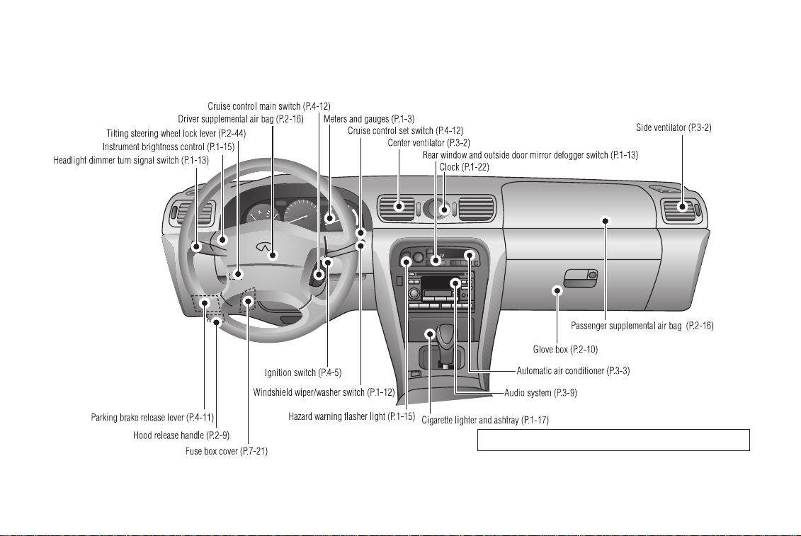
INSTRUMENTS AND CONTROLS
See the page indicated in parentheses for operating details.
SII0122
1-2
Page 8
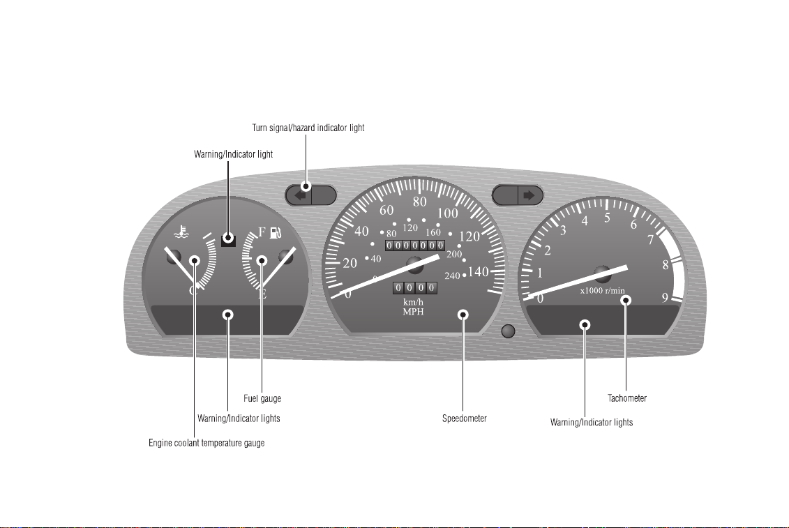
METERS AND GAUGES
H
INSTRUMENTS AND CONTROLS
SII0153
1-3
Page 9
SII0027
SPEEDOMETER
The speedometer indicates vehicle speed.
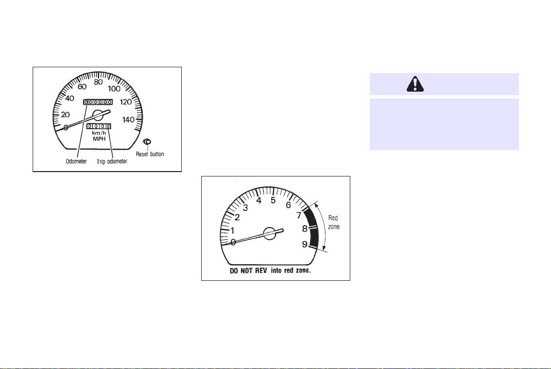
ODOMETER
The odometer records the total mileage the
vehicle has been driven.
INSTRUMENTS AND CONTROLS
TRIP ODOMETER
The trip odometer records the distance of
individual trips. Before each trip, set the trip
odometer to zero by pushing the RESET
button.
TACHOMETER
The tachometer indicates engine speed in
revolutions per minute (r/min).
IIC023M
CAUTION
When engine speed approaches the
red zone, shift to a higher gear.
Operating the engine in the red zone
may cause serious engine damage.
1-4
Page 10
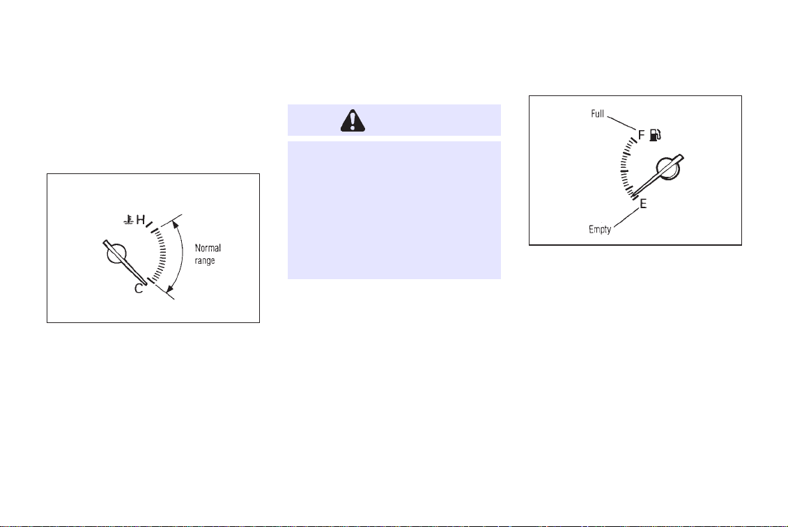
ENGINE COOLANT TEMPERATURE GAUGE
The gauge indicates engine coolant temperature.
IIC024M
Engine coolant temperature will vary with the
outside air temperature and driving conditions.
INSTRUMENTS AND CONTROLS
CAUTION
If the gauge indicates over the normal range, stop the vehicle as soon
as safely possible. If the engine is
overheated, continued operation of
the vehicle may seriously damage
the engine. See ‘‘In case of emergency’’ section for immediate action
required.
FUEL GAUGE
The gauge indicates the APPROXIMATE fuel
level in the tank.
IIC025M
The gauge may move slightly during braking,
turning, acceleration, or going up or down
hill.
The gauge needle is designed to remain in
approximately the same position, even when
the ignition key is turned ‘‘OFF’’.
Refill the fuel tank before the gauge
registers Empty.
1-5
Page 11
INSTRUMENTS AND CONTROLS
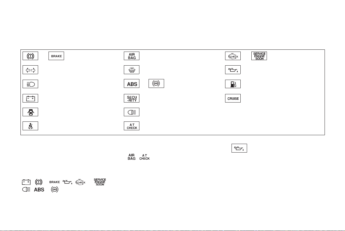
WARNING/INDICATOR LIGHT AND CHIME
or Brake warning light Supplemental air bag warning light or Malfunction indicator light.
Turn signal/hazard indicator lights Low washer fluid warning light Engine oil pressure warning light
High beam indicator light (Blue)
Charge warning light Theft warning light CRUISE indicator light
Door open warning light Stop/tail warning light
Seat belt warning light A/T check light
Checking bulbs
Apply the parking brake and turn the ignition
key to ‘‘ON’’ without starting the engine. The
following lights will come on:
, or , , or ,
, or
The following lights come on briefly and then
or
Anti-lock brake system
warning light
go off:
,
If any light fails to come on, it may indicate a
burned-out bulb or an open circuit in the
electrical system. Have the system repaired
promptly.
1-6
Low fuel warning light
Engine oil pressure warning light
This light warns of low engine oil pressure. If
the light flickers or comes on during normal
driving, pull off the road in a safe area, stop
the engine immediately and call an INFINITI
dealer or other authorized repair shop.
Page 12

INSTRUMENTS AND CONTROLS
The oil pressure warning light is not
designed to indicate a low oil level.
Use the dipstick to check the oil level.
See ‘‘Engine oil’’ in the ‘‘Do-it-yourself’’ section.
CAUTION
Running the engine with the oil pressure warning light on could cause
serious damage to the engine almost immediately. Turn off the engine as soon as it is safe to do so.
See section 5, In case of emergency.
Charge warning light
If the light comes on while the engine is
running, it may indicate that there is something wrong with the charging system. Turn
the engine off and check the alternator belt. If
the belt is loose, broken, missing or if the
light remains on, see your INFINITI dealer
immediately.
CAUTION
Do not continue driving if the belt is
loose, broken or missing. See section 5, In case of emergency.
Low fuel warning light
This light comes on when the fuel in the tank
is getting low. Refuel as soon as it is
convenient, preferably before the fuel gauge
reaches ‘‘E’’.
There should be a small reserve of fuel
remaining in the tank when the fuel
gauge needle reaches ‘‘E’’.
Door open warning light
This light comes on when any of the doors are
1-7
not closed securely while the ignition key is
‘‘ON’’.
Supplemental air bag
warning light
When the ignition key is in the ‘‘ON’’ or
‘‘START’’ position, the supplemental air bag
light will illuminate for about 7 seconds and
then turn off. This means the system is
operational.
If any of the following conditions occur, the
supplemental air bag needs servicing and
your INFINITI must be taken to your nearest
authorized INFINITI dealer.
1. The supplemental air bag light goes off
within 7 seconds.
2. The supplemental air bag light flashes
intermittently or remains on (after 7 seconds).
3. The supplemental air bag light does not
come on at all.
Page 13

INSTRUMENTS AND CONTROLS
Unless checked and repaired, the Supplemental Restraint System may not function properly.
For additional details on the Supplemental Air
Bag System, see section 2.
WARNING
If the supplemental air bag warning
light is on, it could mean that the
supplemental air bag system will not
operate in an accident.
Seat belt warning light
and chime
The light and chime remind you to fasten seat
belts. The light illuminates whenever the
ignition key is turned to ‘‘ON’’, and will remain
illuminated until the driver’s seat belt is
fastened. (When the ignition key is turned to
‘‘ON’’ with the driver’s seat belt fastened, the
light will illuminate for about 7 seconds and
then go off.) At the same time, the chime will
sound for about six seconds unless the
driver’s seat belt is securely fastened.
Refer to ‘‘Seat belts’’ in the ‘‘Pre-driving
checks and adjustments’’ section for precautions on seat belt usage.
If the seat belt warning light blinks, there may
be something wrong with the pre-tensioner
seat belt. In this case, the pre-tensioner will
not operate properly. Have it checked by your
INFINITI dealer.
For additional details on the pre-tensioner
seat belt system, see section 2.
Low washer fluid warning
light
This light comes on when the washer tank
fluid is at a low level. Add washer fluid as
necessary. See the ‘‘Do-it-yourself’’ section.
1-8
or Brake warning
light
This light functions for both the parking brake
and the foot brake systems.
Parking brake indicator:
The light comes on when the parking brake is
applied.
Low brake fluid warning:
The light warns of a low brake fluid level. If the
light comes on while the engine is running
with the parking brake not applied, stop the
vehicle and perform the following:
1. Check the brake fluid level. Add brake fluid
as necessary. See ‘‘Brake and clutch fluid’’
in the ‘‘Do-it-yourself ’’ section.
2. If the brake fluid level is correct:
Have the warning system checked by an
INFINITI dealer.
Page 14

INSTRUMENTS AND CONTROLS
WARNING
●
Your brake system may not be
working properly if the warning
light is on. Driving could be dangerous. If you judge it to be safe,
drive carefully to the nearest service station for repairs. Otherwise, have your vehicle towed.
●
Pressing the brake pedal with the
engine stopped could increase
your stopping distance and require greater pedal effort as well
as pedal travel.
●
If the level is below the MINIMUM
mark on the brake fluid reservoir,
do not drive until the brake system has been checked at an
INFINITI dealer.
or Anti-lock brake
warning light
If the light comes on while the engine is
running, it may indicate there is something
wrong with the anti-lock portion of the brake
system. In either case, have the system
checked by your INFINITI dealer.
If an abnormality occurs in the system, the
anti-lock function will cease but the ordinary
brakes will continue to operate normally.
If the light comes on while you are
driving, contact your INFINITI dealer for
repair.
A/T check
When the ignition switch is turned ON, the
light comes on for 2 seconds. If the light
blinks for approximately 8 seconds, it may
indicate that there is something wrong with
the transmission. Have your INFINITI dealer
check and repair the transmission.
1-9
Turn signal/hazard indicator lights
The light flashes when the turn signal switch
lever or hazard switch is turned on.
Stop/tail warning light
If the light comes on with the engine running
and with the light switch on, or when the brake
pedal is depressed, one or more stop/tail light
bulbs are burned out. Replace the stop/tail
light bulb.
High beam indicator light
(Blue)
This light comes on when the headlight high
beam is on and goes out when the low beam
is selected.
CRUISE indicator light
The light comes on while the vehicle speed is
controlled by the cruise control system.
Page 15

INSTRUMENTS AND CONTROLS
Key reminder chime
The chime will sound if the driver side door is
opened while the key is left in the ignition
switch. Remove the key and take it with you
when leaving the vehicle.
Light reminder chime
A chime will sound when the driver side door
is opened if the light switch is turned on
(ignition switch is turned off).
Turn the light switch off when you leave the
vehicle.
Brake pad wear warning
The disc brake pads have audible wear warnings. When a brake pad requires replacement,
it will make a high pitched scraping sound
when the vehicle is in motion whether or not
the brake pedal is depressed. Have the brakes
checked as soon as possible if the warning
sound is heard.
or Malfunction indi-
cator light (MIL)
If the Malfunction indicator light comes on
steady or blinks while the engine is running,
it may indicate a potential emission control
problem.
The Malfunction indicator light will come on
in one of two ways:
● Malfunction indicator light on steady —
An emission control system malfunction
has been detected. Have the vehicle
inspected by an authorized INFINITI
dealer. You do not need to have your
vehicle towed to the dealer.
● Malfunction indicator light blinking — An
engine misfire has been detected which
may damage the emission control system.
To reduce or avoid emission control system damage:
* do not drive at speeds above 45 MPH
(72 km/h).
1-10
* avoid hard acceleration or deceleration.
* avoid steep uphill grades.
* if possible, reduce the amount of cargo
being hauled or towed.
The malfunction indicator light may stop
blinking and come on steady.
Have the vehicle inspected by an authorized INFINITI dealer. You do not need to
have your vehicle towed to the dealer.
CAUTION
Continued vehicle operation without
having the emission control system
checked and repaired as necessary
could lead to poor driveability, reduced fuel economy, and possible
damage to the emission control system, which may affect your warranty
coverage.
Page 16

INSTRUMENTS AND CONTROLS
Some conditions may cause the malfunction
indicator light to come on steady or blink. For
example, running the vehicle out of fuel,
which causes the engine to misfire, may cause
the malfunction indicator light to come on
steady or blink.
If you suspect that you experienced such a
condition, drive the vehicle to an authorized
INFINITI dealer and have the vehicle inspected. Avoid any unnecessary diagnosis
during the service by informing the dealer of
the condition that may have occurred.
THEFT WARNING
The theft warning system provides visual and
audio alarm signals if parts of the vehicle are
disturbed.
How to activate the theft warning system
1. Close all windows.
2. Remove the key from the ignition switch.
3. Close and lock all doors, hood and trunk
lid. The doors can be locked either with or
without the key.
The system can be activated even if the
windows are open.
4. Confirm that the indicator light comes on.
The light will glow for about 30 seconds
and then go out. The system is now
activated. If, during this 30 second time
period, the door is unlocked or the ignition
key is turned to ‘‘ACC’’ or ‘‘ON’’, the system
will not activate.
● If the key is turned slowly toward the
front of the vehicle when locking the
door, the system may not activate. If
the key is returned beyond the vertical position toward the rear of the
vehicle to remove the key, the system may be deactivated. When the
indicator light fails to glow for 30
seconds, unlock the door once and
lock it again.
1-11
● Even when the driver and/or passengers are in the vehicle, the system
will activate with all doors, hood and
trunk lid locked and ignition key off.
Turn the ignition key to ‘‘ACC’’ to
turn the system off.
Theft warning system operation
The warning system will give the following
alarm:
● The headlights blink and the horn sounds
intermittently. In addition, the starter motor
will not operate.
● The alarm automatically turns off after 2 to
4 minutes; however, the alarm will reactivate if the vehicle is tampered with again.
The alarm is activated by:
● Unlocking the door or opening the trunk
lid without using the key or multi-remote
controller. (Even if the door is opened by
releasing the door inside lock knob or the
Page 17
INSTRUMENTS AND CONTROLS
trunk lid is opened by operating the trunk
lid release switch, the alarm is activated.)
● Opening the hood.
● Pushing in or pulling out of the key
cylinder on the door or trunk lid.
How to stop alarms
The alarm will stop only by unlocking a door
or trunklid with the key.The alarm willnot stop
if the ignition switch is turned to ‘‘ACC’’ or
‘‘ON’’.
If the system does not operate as described above, have it checked by your
INFINITI dealer.
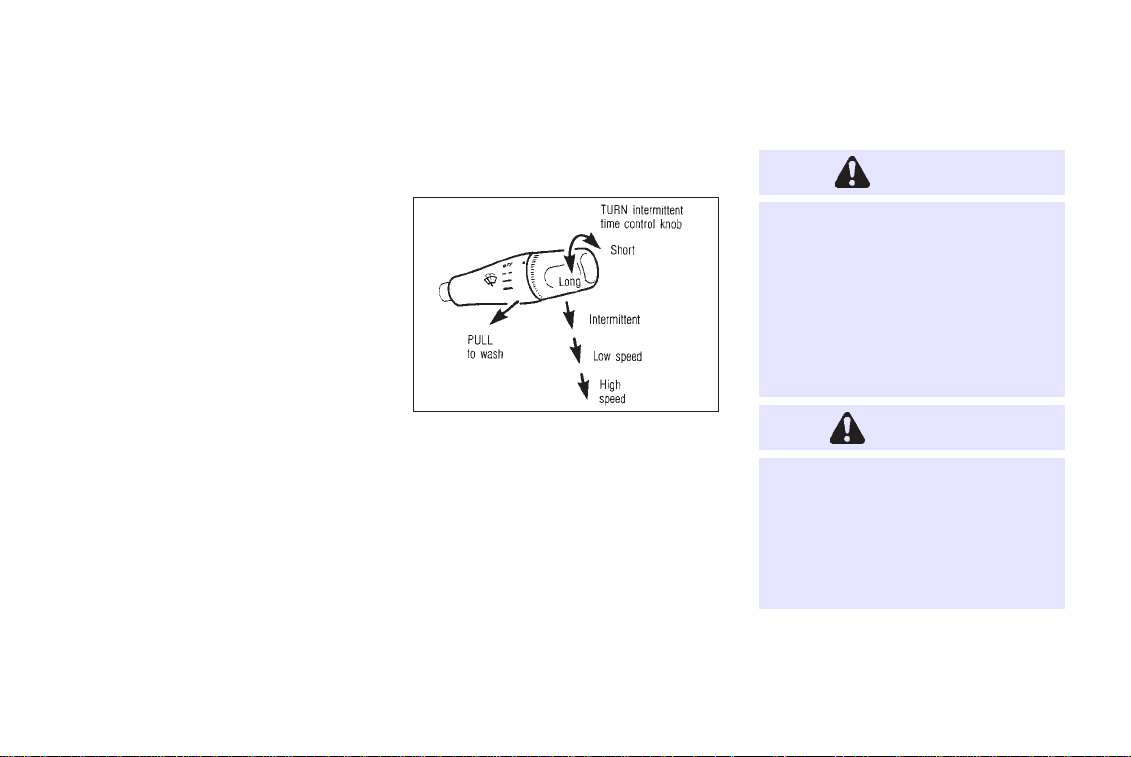
WINDSHIELD WIPER AND
WASHER SWITCH
IIC026MA
The windshield wiper and washer operates
when the ignition key is in the ‘‘ACC’’ or ‘‘ON’’
position.
Push the lever down to operate the wiper. Pull
the lever toward you to operate the washer.
Intermittent operation can be adjusted from 4
to 12 seconds by turning the knob.
1-12
CAUTION
The following could damage the
washer system:
●
Do not operate the washer continuously for more than 30 seconds.
●
Do not operate the washer if the
reservoir tank is empty.
WARNING
In freezing temperatures the washer
solution may freeze on the windshield and obscure your vision which
may lead to an accident. Warm the
windshield with the defroster before
you wash the windshield.
Page 18
INSTRUMENTS AND CONTROLS
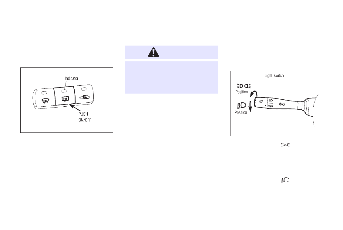
REAR WINDOW AND OUTSIDE DOOR MIRROR DEFOGGER SWITCH
IIC027M
To defog the rear window glass and the
outside door mirrors, start the engine and
push the switch on. (The indicator light will
come on.) Push the switch again to turn the
defogger off.
It will automatically turn off in approximately
15 minutes.
CAUTION
When cleaning the inner side of the
rear window, be careful not to
scratch or damage the rear window
defogger.
1-13
HEADLIGHT AND TURN
SIGNAL SWITCH
Lighting
SII0014
Turn the switch to the ‘‘ ’’ position:
The parking, front and rear side marker, tail,
license plate and instrument lights will come
on.
Turn the switch to the ‘‘
Headlights will come on and all the other
lights remain on.
’’ position:
Page 19
INSTRUMENTS AND CONTROLS
Daytime running light system
(For Canada)
The headlights automatically illuminate at a
reduced intensity when the engine is started
with the parking brake released. The daytime
running lights operate with the headlight
switch in the ‘‘OFF’’ position or in the ‘‘
position. Turn the headlight switch to the
‘‘
’’ position for full illumination when
driving at night.
If the parking brake is applied before the
engine is started, the daytime running lights
do not illuminate. The daytime running lights
illuminate once the parking brake is released.
The daytime running lights will remain on
until the ignition switch is turned off.
WARNING
When the daytime running light system is active, tail lights on your
vehicle will not be on. It is necessary
’’
at dusk to turn on your headlights.
Failure to do so could cause an
accident injuring yourself and others.
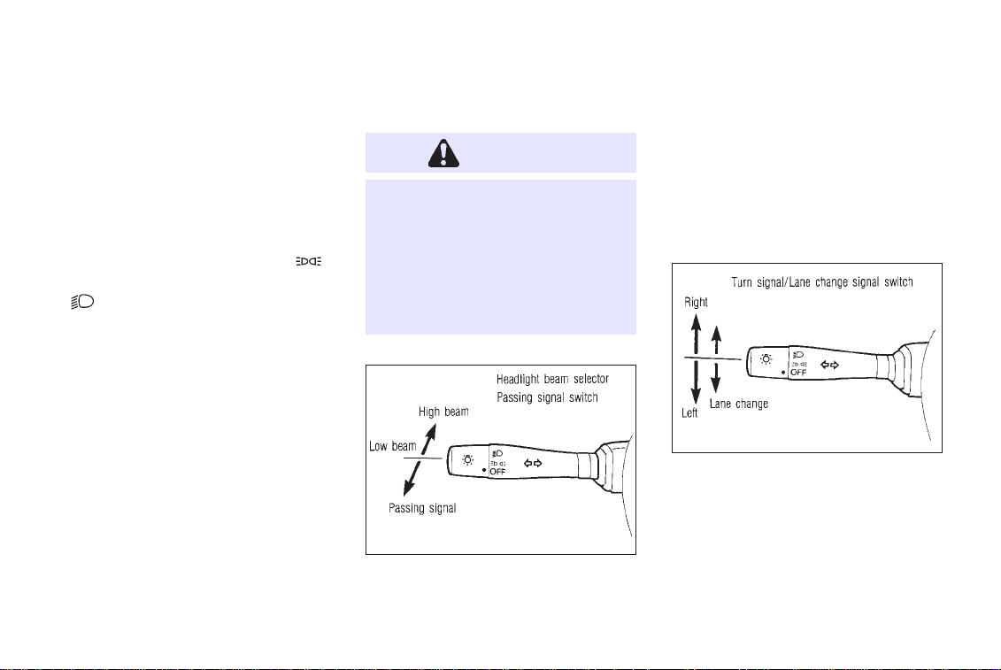
To select the high beam, push the lever for-
1-14
SII0015
ward. Pull it back to select the low beam.
Passing signal
Pulling the lever toward you will flash the
headlight high beam.
Turn signal
SII0016
Move the lever up or down to signal the
turning direction. When the turn is completed,
the turn signals cancel automatically.
Lane change signal
To indicate a lane change, move the lever up
Page 20
INSTRUMENTS AND CONTROLS
or down to the point where lights begin
flashing.
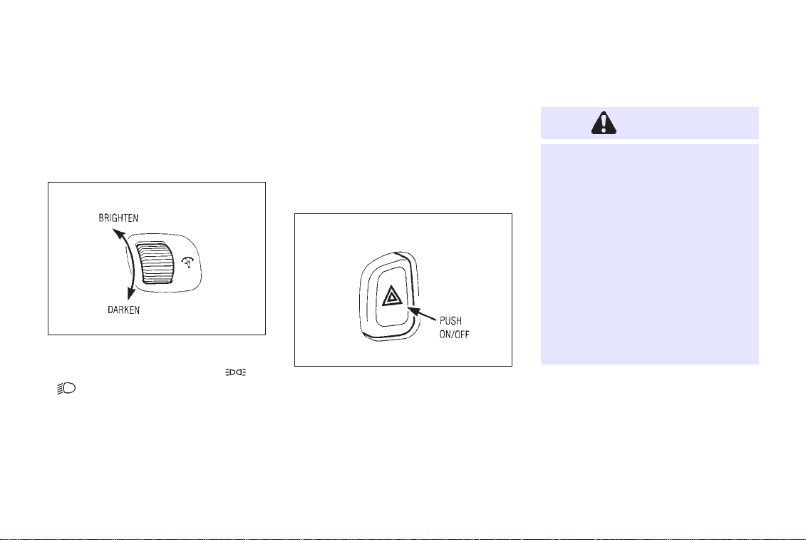
INSTRUMENT BRIGHTNESS CONTROL
IIC028M
The instrument brightness control operates
when the head light switch is in the ‘‘
’’ position.
‘‘
Turn the control to adjust the brightness of the
instrument panel lights.
When the control is turned in the upper
direction until a click sound is heard, the light
’’ or
intensity will be at maximum. When the
control is turned in the lower direction until a
click sound is heard, the light will be turned
off.
HAZARD WARNING
FLASHER SWITCH
IIC029M
Push the switch on to warn other drivers when
you must stop or park under emergency conditions. All turn signal lights will flash.
1-15
WARNING
●
When stalled or stopped on the
roadway under emergency conditions, move the vehicle well off
the road.
●
Do not use the switch while moving on the highway unless unusual circumstances force you to
drive so slowly that your vehicle
might become a hazard to other
traffic.
●
Turn signals do not work when the
switch is operating.
The flasher can be actuated with the ignition
switch either off or on.
Some state laws may prohibit the use of
the hazard warning flasher switch while
driving.
Page 21
INSTRUMENTS AND CONTROLS
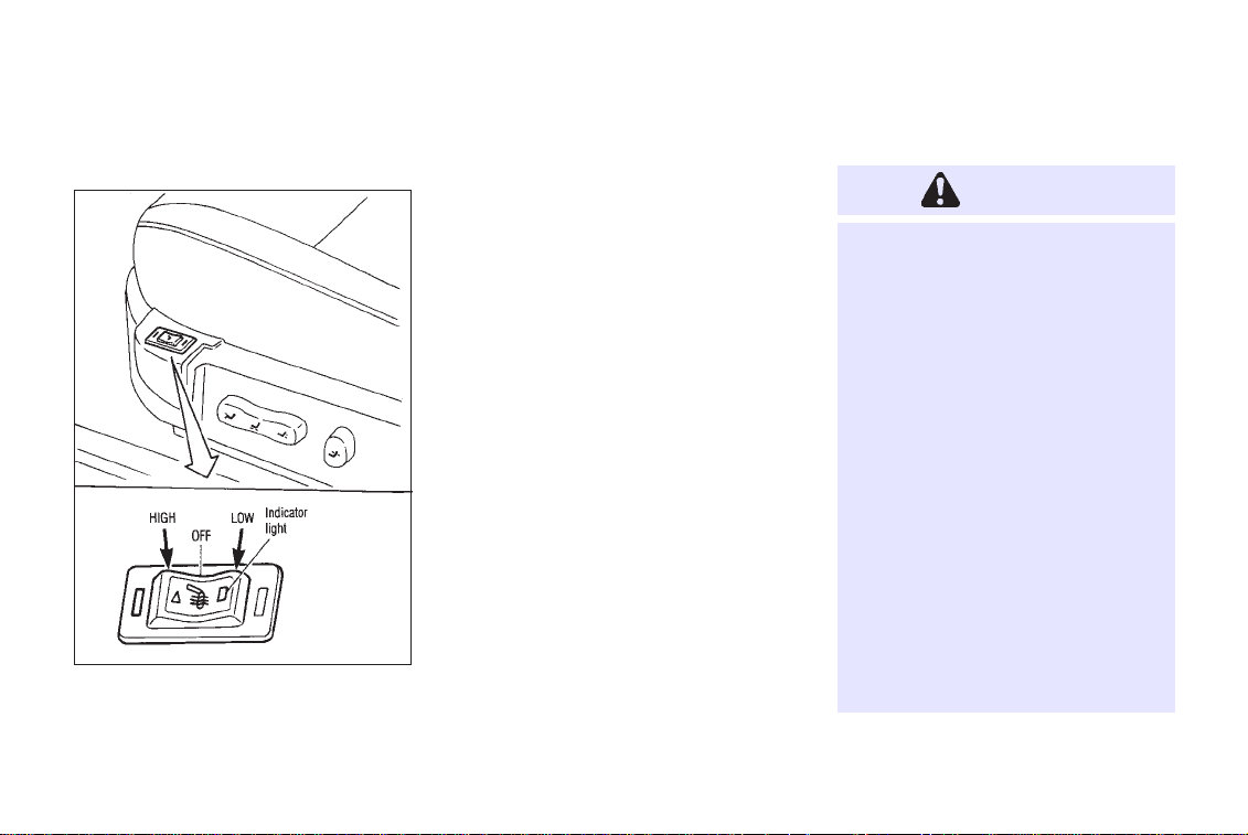
HEATED SEAT
IIC037
The front seats are warmed by built-in heaters.
The switches located on the side part of the
seats can be operated independently of each
other.
1. Start the engine.
The battery could run down if the heater
is operated while the engine is not
running.
2. Push the ‘‘LO’’ or ‘‘HI’’ position of the
switch, as desired, depending on the temperature. The indicator light in the switch
will illuminate.
The heater is controlled by a thermostat,
automatically turning the heater on and off.
The indicator light will remain on as long
as the switch is on.
3. When the vehicle’s interior is warmed or
before you leave the vehicle, be sure to
turn the switch off.
1-16
CAUTION
Do not use the seat heater for a long
time or when no one is seated there.
●
Do not put anything on the seat
which insulates heat, such as a
blanket, cushion, seat cover, etc.
Otherwise, the seat may become
overheated.
●
Do not place anything hard or
heavy on the seat or pierce it with
a pin or similar object. This may
result in damage to the heater.
●
Any liquid spilled on the heating
seat should be immediately
wiped up with a dry cloth.
●
When cleaning the seat, never
use benzine, thinner, or any similar materials.
Page 22
INSTRUMENTS AND CONTROLS
●
If any abnormalities are found or
the heating seat does not operate, turn the switch OFF and have
the system checked by your
INFINITI dealer.
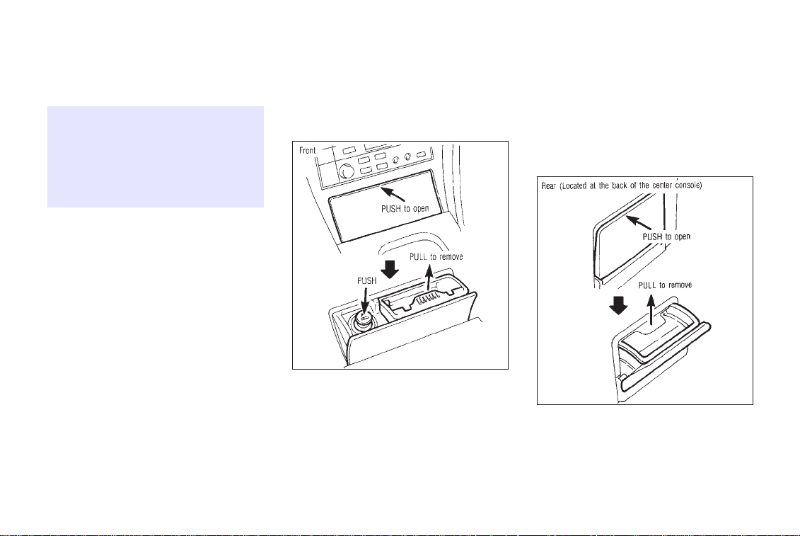
CIGARETTE LIGHTERS
AND ASHTRAYS
SII0069
The cigarette lighter operates when the ignition switch is in the ‘‘ACC’’ or ‘‘ON’’ position.
Push the lighter in all the way, then release it.
When the lighter is heated, it will spring out.
1-17
Return the lighter to its original position after
use.
To empty the ashtray, pull up on the horizontal
bar and remove the tray.
SII0070A
Page 23
WARNING
The cigarette lighter should not be
used while driving in order that full
attention may be given to the driving
operation.
CAUTION
The cigarette lighter socket is a
power source for the cigarette
lighter element only. The use of the
cigarette lighter socket as a power
source for any other accessory is not
recommended.
INSTRUMENTS AND CONTROLS
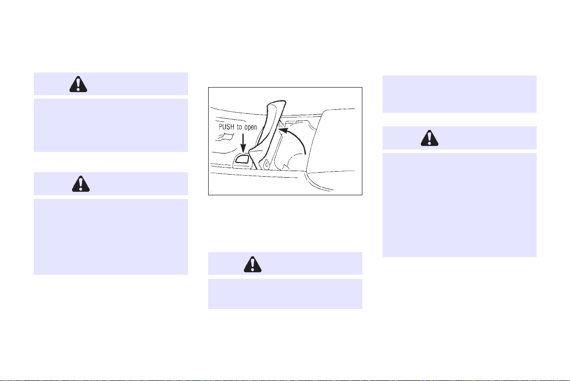
CUP HOLDER
IIC031M
To open, push the cup holder opener switch.
To close, lower the cup holder lid and push
down lightly.
WARNING
●
The cup holder should not be
used while driving in order that
full attention may be given to the
driving operation.
CAUTION
●
Avoid abrupt starting and braking
when the cup holder is being used
to prevent spilling the drink. If the
liquid is hot, it can scald you or
your passenger.
●
Use only soft cups in the cup
holder. Hard objects can injure
you in an accident.
1-18
Page 24
INSTRUMENTS AND CONTROLS
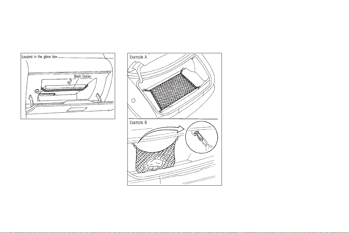
BOOK HOLDER CARGO NET
IIC042MA
● Do not put heavy objects in the cargo
net. The net is designed only to hold
light packages or objects in place
while driving.
IIC044M
1-19
Page 25
INSTRUMENTS AND CONTROLS
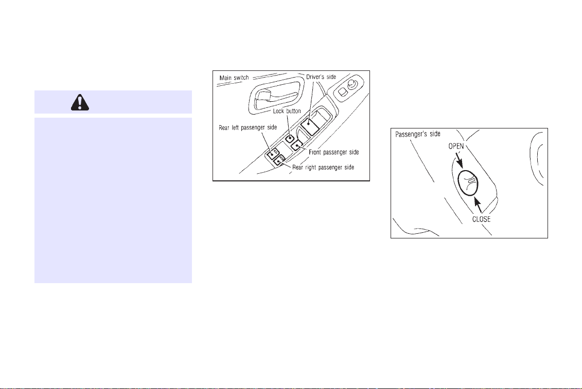
POWER WINDOW
WARNING
●
Make sure that all passengers
have their hands, etc. inside the
vehicle before closing the windows. Use the window lock switch
to prevent unexpected use of the
power windows.
●
Do not leave children unattended
inside the vehicle. They could
unknowingly activate switches or
controls and become trapped in a
window. Unattended children
could become involved in serious
accidents.
The power windows only operate when the
ignition key is in the ‘‘ON’’ position.
SII0025A
To open or close the window, push down or
pull up the switch and hold it. The main
switch (driver side switches) will open or
close all the windows.
1-20
Locking passenger’s window
When the lock button is pushed in, only the
driver side window can be opened or closed.
Push it in again to cancel.
IIC033M
The passenger side switch will open or close
only the corresponding window. To open or
close the window, hold the switch down or up.
Page 26
INSTRUMENTS AND CONTROLS
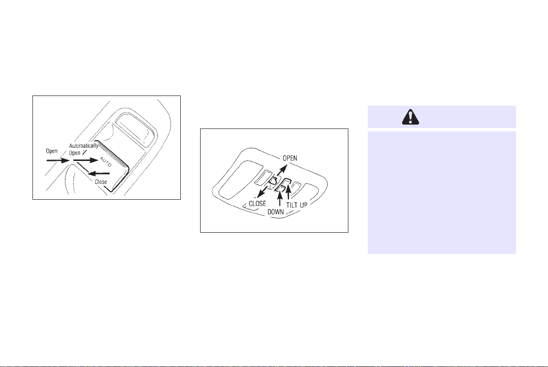
POWER WINDOW AUTOMATIC SWITCH
SII0152
To fully open the driver side window, completely press down the switch and release it; it
need not be held. The window will automatically open all the way. To stop the window,
just pull up the switch toward the ‘‘CLOSE’’
side.
A light press on the switch will cause the
window to open until the switch is released.
SUNROOF
The sunroof will only operate when the ignition key is in the ‘‘ON’’ position.
Sliding the sunroof
IIC035M
To open the roof, keep pressing the switch to
the ‘‘OPEN’’ side.
To close the roof, keep pressing the switch to
the ‘‘CLOSE’’ side.
Tilting the sunroof
To tilt up, first close the sunroof, then keep
1-21
pushing the ‘‘UP’’ side of the tilt switch. To tilt
down the sunroof, keep pushing the ‘‘DOWN’’
side.
WARNING
●
In an accident you could be
thrown from the vehicle through
an open sunroof. Always use seat
belts and child restraints properly.
●
Do not allow anyone to stand up
or extend any portion of their
body out of the opening while the
vehicle is in motion or while the
sunroof is closing.
Page 27
CAUTION
●
Remove water drops, snow, ice
or sand from the sunroof before
opening.
●
Do not place any heavy object on
the sunroof or surrounding area.
INSTRUMENTS AND CONTROLS
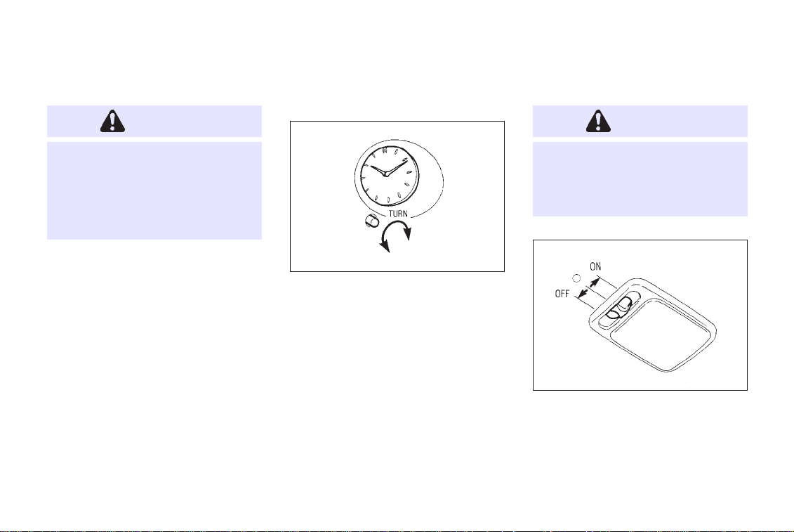
CLOCK
CAUTION
Leaving the interior light switch in
the ON position for extended periods
of time will result in a discharged
battery.
IF THE SUNROOF DOES NOT
CLOSE
Have your INFINITI dealer check and repair the
sunroof.
SII0068
The time can be adjusted by turning the knob.
INTERIOR LIGHT
The interior light has a three-position switch.
When the switch is in the center ‘‘j’’ posi-
tion, the light will illuminate when a door is
opened.
1-22
IIC038M
Page 28
INSTRUMENTS AND CONTROLS
Illuminated entry system
When the light switch is set at the center ‘‘j’’
position and the front door handle is pulled
and released once, the interior light and
ignition key light will come on and gradually
go out. This system is helpful at night to
locate the ignition key slot or check the
vehicle interior.
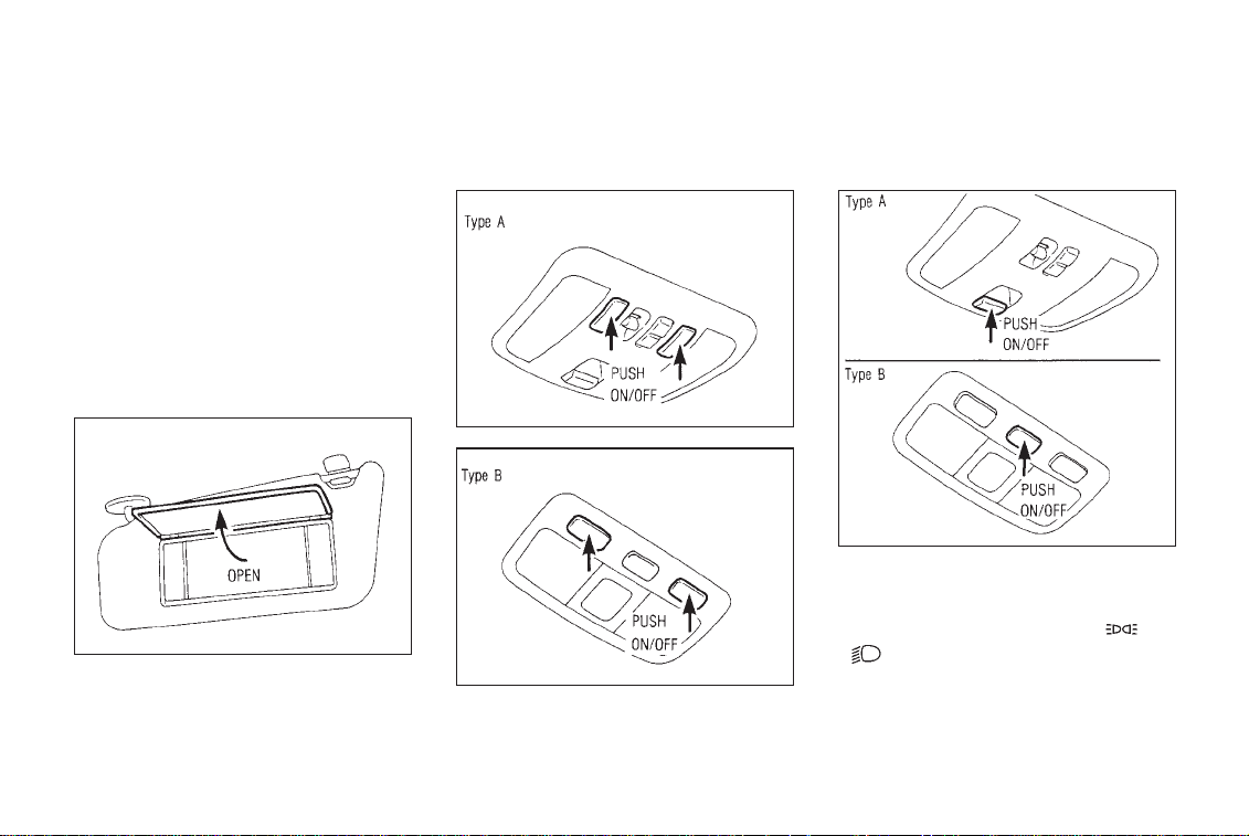
VANITY MIRROR LIGHT
IIC041M
The light on the vanity mirror will turn on
when the cover on the vanity mirror is opened.
PERSONAL LIGHT CONSOLE LIGHT
IIC039M
With the console light switch turned on, the
light will come on by turning the headlight
and turn signal switch to the ‘‘
‘‘
IIC040M
1-23
’’ position. The light is designed to
illuminate the switches, etc. on the center
console and the automatic transmission shift
IPD075M
’’ or
Page 29

lever to make them easier to see and use at
night.
Normally, keep the console light switch turned
on. Switch off the console light when not
needed.
INSTRUMENTS AND CONTROLS
1-24
Page 30

2 PRE-DRIVING CHECKS AND ADJUSTMENTS
Key ............................................................. 2-2
Door locks .................................................. 2-2
Multi-remote control system ...................... 2-5
Hood release .............................................. 2-9
Glove box lock ......................................... 2-10
Trunk lid lock ........................................... 2-10
Fuel filler lid lock ...................................... 2-11
Seats ........................................................ 2-13
Supplemental restraint system
(Supplemental air bag system) ................ 2-16
Warning labels ......................................... 2-25
Supplemental air bag warning light ......... 2-25
Seat belts ................................................. 2-27
Child restraints for infants and
small children............................................ 2-35
Tilting steering wheel ............................... 2-44
Outside mirror remote control ................. 2-44
Foldable outside mirrors .......................... 2-45
Automatic anti-dazzling inside mirror ...... 2-45
Center sunvisor ........................................ 2-45
Page 31

PRE-DRIVING CHECKS AND ADJUSTMENTS
KEY
SIP0003A
The master key and wallet key can be used for
all the locks. The security key cannot be used
for the trunk lid or glove box locks. To protect
belongings when you leave a key with someone, give them the security key only. Never
leave this key in the vehicle.
Record the key number on the key number
plate and keep it in a safe place (such as your
wallet), NOT IN THE CAR. A key number plate
is supplied with your key. Keep the plate in a
safe place. INFINITI does not record key
numbers so it is very important to keep track
of your key number plate.
A key number is only necessary when you
have lost all keys and do not have one to
duplicate from. If you still have a key, this key
can be duplicated by your INFINITI dealer or a
lock smith shop.
2-2
DOOR LOCKS
Locking front doors with key
IPD054M
To lock the door, turn the key toward the front
of the vehicle.
To unlock, turn it toward the rear.
Locking the front door will simultaneously
lock the other doors.
Page 32

PRE-DRIVING CHECKS AND ADJUSTMENTS
Locking the doors without key
SIP0122
To lock from the outside without a key, move
the inside lock knob to the ‘‘LOCK’’ position.
Then close the door.
When locking the door this way, be certain not
to leave the key inside the vehicle.
WARNING
●
Always have the doors locked
while driving. Along with the use
of seat belts, this provides
greater safety in the event of an
accident by helping to prevent
persons from being thrown from
the vehicle. This also helps keep
children and others from unintentionally opening the doors, and
will help keep out intruders.
●
Before opening any door, always
look for and avoid oncoming traffic.
●
Do not leave children unattended
inside the vehicle. They could
unknowingly activate switches or
controls. Unattended children
could become involved in serious
accidents.
2-3
CHILD SAFETY REAR DOOR
LOCK
SIP0005
Child safety locking helps prevent doors from
being opened accidentally, especially when
small children are in the vehicle.
When the lever is in the lock position,
the rear door can be opened only from
the outside.
Page 33

PRE-DRIVING CHECKS AND ADJUSTMENTS
POWER DOOR LOCK
The power door lock system allows you to
lock or unlock all doors simultaneously.
SIP0089
● Turning the front door key to the front of
the vehicle will lock all doors.
● Turning the front door key one time to the
rear of the vehicle will unlock the corresponding door. From that position, returning the key to Neutral (where the key can
only be removed and inserted.) and turning it to the rear again within 3 seconds
will unlock all doors.
● Pushing the front door lock knob in will
lock all doors.
If the front doors are open with the key
in the ignition when the inside lock
knob is set to the lock position, all door
knobs will unlock. When the open front
door is closed, all the knobs will lock
then quickly unlock automatically.
IPD057M
● Operating the lock-unlock switch will lock
or unlock all doors.
2-4
WARNING
●
Before opening the door, always
look for and avoid oncoming traffic.
●
Do not leave children unattended
inside the vehicle. They could
unknowingly activate switches or
controls. Unattended children
could become involved in serious
accidents.
Page 34

PRE-DRIVING CHECKS AND ADJUSTMENTS
MULTI-REMOTE CONTROL
SYSTEM
It is possible to lock/unlock all doors, to open
the driver’s and front passenger’s windows, to
release the trunk lid and to turn on or off the
interior light by using the remote controller
from outside the car.
Be sure to remove the key from the
vehicle before locking the doors and
leaving it.
The remote controller can operate at a distance of approximately 49 ft (15 m) from the
vehicle. (The effective distance depends upon
the conditions around the vehicle.)
As many as four remote controllers can be
used with one vehicle. For information concerning the purchase and use of additional
remote controllers, contact your INFINITI
dealer.
CAUTION
Listed below are conditions or occurrences which will damage the
remote controller.
●
Do not allow the remote controller to become wet.
●
Do not drop the remote controller.
●
Do not strike the remote controller sharply against another object.
●
Do not place the remote controller for an extended period in an
area where temperatures exceed
140°F (60°C).
2-5
Page 35

PRE-DRIVING CHECKS AND ADJUSTMENTS
HOW TO USE MULTI-REMOTE
CONTROL SYSTEM
Locking doors
1. Remove the ignition key.
2. Close all doors.
3. Push the lock button on the remote controller.
4. All doors will lock.
5. The hazard indicator flashes twice.
● When the lock button is pushed with all
doors locked, the hazard indicator flashes
twice as a reminder that the doors are
already locked.
IPD052M
2-6
Page 36

PRE-DRIVING CHECKS AND ADJUSTMENTS
Unlocking doors
1. Push the unlock button on the remote
controller.
2. Only the driver side door will unlock. Push
the unlock button on the remote controller
again within 3 seconds.
3. All doors will unlock.
4. The interior light will stay on for 30
seconds when the interior light switch is in
the center ‘‘p’’ position.
The interior light can be turned off without
waiting for 30 seconds by inserting the key
into the ignition or by locking the doors with
the remote controller or by pushing the
interior light button.
Releasing the trunk lid
1. Push the trunk lid release button for longer
than 1.0 seconds.
2. The trunk lid will open.
The trunk will not open with the trunk
lid release cancel switch turned to OFF.
(See ‘‘Trunk lid lock’’ for details.)
Using the interior light
1. Push the interior light button.
2. The interior light will stay on for 30
seconds when the interior light switch is in
the center ‘‘p’’ position.
The interior light can be turned off without
waiting for 30 seconds by locking the doors
with the remote controller or by pushing the
interior light button or by inserting the key
into the ignition.
Using the panic alarm
If you are near your vehicle and feel threatened, you may activate the alarm to call
attention as follows:
1. Push the lock button on the remote controller for longer than 1.5 seconds.
2. The theft warning alarm and headlight will
2-7
stay on for 30 seconds.
3. The alarm will stop when any of the key
functions are used.
SIP0086
Page 37

PRE-DRIVING CHECKS AND ADJUSTMENTS
BATTERY REPLACEMENT
Replace the battery as follows:
1. Open the lid using a suitable tool.
2. Replace the battery with a new one.
Recommended battery: Sanyo CR2025 or
equivalent
3. Close the lid securely.
4. Press the key button two or three times to
check its operation.
If the battery is removed for any reason
other than replacement, perform step 4
above.
● An improperly disposed battery can
hurt the environment. Always confirm local regulations for battery disposal.
● The remote controller is water-proof;
however, if it does get wet, immediately wipe completely dry.
● The operational range of the remote
controller extends to approximately
49 ft (15 m) from the vehicle.
This range may vary with conditions.
FCC Notice:
Changes or modifications not expressly
approved by the manufacturers compliance could void the user’s authority to
operate the equipment.
This device complies with Part 15 of the
FCC Rules and RSS-210 of Industry
Canada.
Operation is subject to the following
two conditions: (1) This device may not
cause harmful interference, and (2) this
device must accept any interference
received, including interference that
may cause undesired operation of the
device.
2-8
Page 38

PRE-DRIVING CHECKS AND ADJUSTMENTS
HOOD RELEASE
1. Pull the hood lock release handle located
below the instrument panel; the hood will
then spring up slightly.
2. Pull the lever at the front of the hood with
your fingertips and raise the hood.
3. When closing the hood, slowly close the
hood and make sure it locks into place.
WARNING
●
Make sure the hood is completely
closed and latched before driving. Failure to do so could cause
the hood to fly open and result in
an accident.
IPD058M
●
If you see steam or smoke coming
from the engine compartment, to
avoid injury, do not open the
hood.
2-9
Page 39

GLOVE BOX LOCK
PRE-DRIVING CHECKS AND ADJUSTMENTS
CAUTION
Keep the glove box lid closed while
driving to help prevent injury in an
accident or a sudden stop.
IPD059M
When locking or unlocking the glove box, use
the master key or wallet key.
The glove box may be opened by pulling the
handle.
TRUNK LID LOCK
Trunk lid release switch operation
The trunk lid release switch is located on the
driver’s side door panel.
2-10
IPD060M
To open the trunk lid, pull the release switch.
To close, push the trunk lid down securely.
Page 40

PRE-DRIVING CHECKS AND ADJUSTMENTS
Key operation
IPD061M
To open the trunk lid, turn the key clockwise.
To close, lower and push the trunk lid down
securely.
WARNING
Do not drive with the trunk lid open.
This could allow dangerous exhaust
gases to be drawn into the vehicle.
See ‘‘Exhaust gas’’ in the ‘‘Starting
and driving’’ section.
TRUNK LID RELEASE CANCEL SWITCH
IPD062M
When the cancel switch located inside the
glove box is ‘‘OFF’’, the trunk lid cannot be
opened with the trunk lid release switch or the
remote controller. It can be opened only with
the master key or wallet key.
2-11
FUEL FILLER LID LOCK
Opener switch
IPD063M
To open the fuel filler lid, push the opener
switch. To lock, close the fuel filler lid
securely.
Page 41

PRE-DRIVING CHECKS AND ADJUSTMENTS
FUEL FILLER CAP
IPD064M
The fuel filler cap is a screw-on ratcheting
type. Tighten the cap clockwise until ratcheting clicks are heard.
WARNING
●
Gasoline is extremely flammable
and highly explosive under certain conditions. You could be
burned or seriously injured if it is
misused or mishandled. Always
stop the engine and do not smoke
or allow open flames or sparks
near the vehicle when refueling.
●
Fuel may be under pressure. Turn
the cap one-half turn and wait for
any ‘‘hissing’’ sound to stop, to
prevent fuel from spraying out
and possible personal injury.
Then remove the cap.
●
Use only a genuine fuel filler cap
as a replacement. It has a built-in
safety valve needed for proper
operation of the fuel system and
emission control system. An incorrect cap can result in a serious
malfunction and possible injury.
CAUTION
If fuel is spilled on the car body,
flush it away with water to avoid
paint damage.
FUEL FILLER CAP HOLDER
IPD065M
Put the fuel filler cap on the cap holder while
refueling.
2-12
Page 42
PRE-DRIVING CHECKS AND ADJUSTMENTS
SEATS
POWER SEAT
WARNING
●
Do not adjust the driver’s seat
while driving in order that full
attention may be given to the
driving operation.
●
The seatback should not be reclined any more than needed for
comfort. Seat belts are most effective when the occupant sits
well back and straight up in the
seat. If the seatback is reclined,
the risk of sliding under the lap
belt and being injured is increased.
●
Do not leave children unattended
inside the vehicle. They could
unknowingly activate switches or
controls. Unattended children
could become involved in serious
accidents.
Operating tips
● The power seat motor has an auto-reset
overload protection circuit. If the motor
stops during operation, wait 30 seconds,
then reactivate the switch.
● Do not operate the power seat for a long
period of time when the engine is off. This
will discharge the battery.
2-13
Forward and backward
SIP0022A
Pressing the switch forward or backward will
slide the seat forward or backward to the
desired position.
Page 43

Reclining
PRE-DRIVING CHECKS AND ADJUSTMENTS
SIP0150 SIP0151
SIP0023
Moving the recline switch forward or backward will move the seatback forward or
backward to the desired position.
WARNING
Do not ride in a moving vehicle when
the seatback is reclined. This can be
dangerous. The shoulder belt will
2-14
Page 44

PRE-DRIVING CHECKS AND ADJUSTMENTS
not be against your body. In an
accident you could be thrown into it
and receive neck or other serious
injuries. You could also slide under
the lap belt and receive serious internal injuries.
For most effective protection when
the vehicle is in motion, the seat
should be upright. Always sit well
back in the seat and adjust the seat
belt properly. See ‘‘Precautions on
seat belt usage’’ later in this chapter.
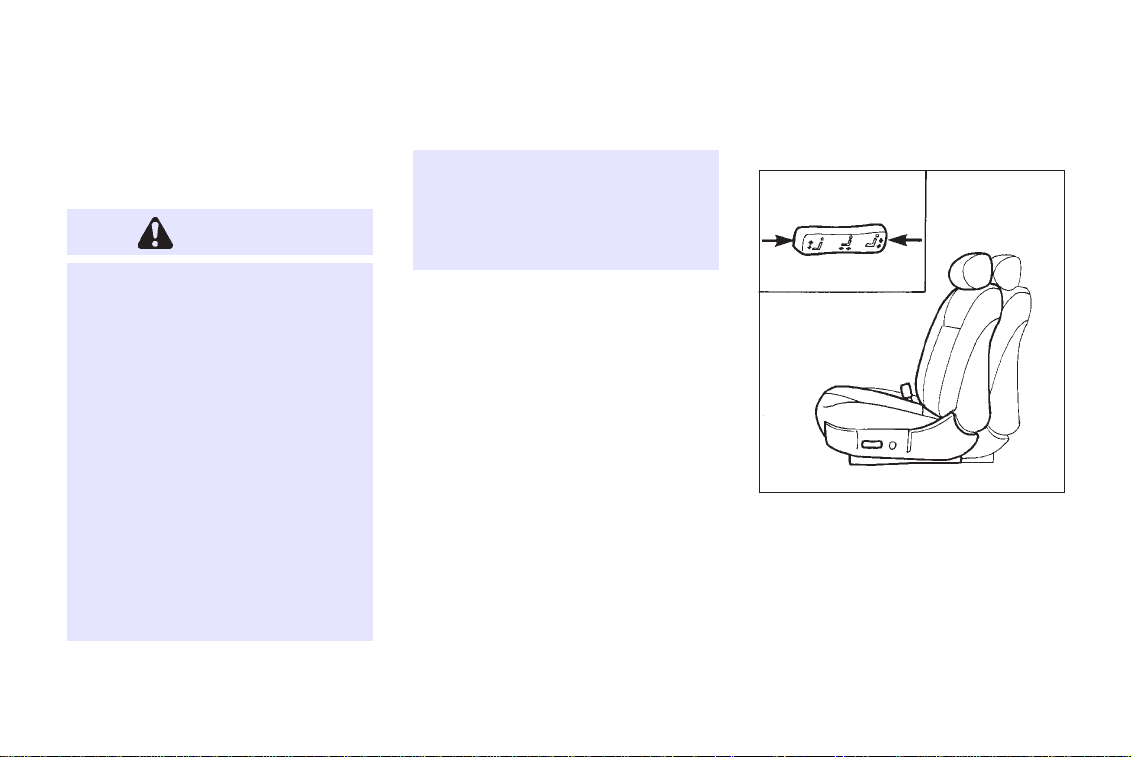
Seat lifter
IPD074M SIP0038
Pull or lower either side of the switch to adjust
the seat cushion to the desired angle and
height.
2-15
Lumbar support (Driver’s seat)
Push either side of the switch to adjust the
seat lumbar area.
Page 45

PRE-DRIVING CHECKS AND ADJUSTMENTS
HEAD RESTRAINTS
Adjust the top of the head restraint level with
the top of your ears.
IPD082M
To raise the head restraint, just pull it up. To
lower, push the lock knob and push the head
restraint down.
WARNING
Head restraints should be adjusted
properly as they may provide significant protection against injury in an
accident. Do not remove them.
Check the adjustment after someone
else uses the seat.
IPD083M
To adjust the head restraint, push it forward or
rearward as shown.
2-16
SUPPLEMENTAL
RESTRAINT SYSTEM
(SUPPLEMENTAL AIR BAG
SYSTEM)
This Supplemental Restraint System section
contains important information concerning the
driver and passenger supplemental air bags
and pre-tensioner seat belt. The Supplemental
Restraint System Air Bag can help reduce
impact force to the driver and to the front
passenger in certain frontal collisions. The
supplemental air bags are designed to
supplement the crash protection provided
by the driver and front passenger seat belts
and are not a substitute for them. Seat belts
should always be correctly worn and the driver
and front passenger seated a suitable distance
away from the steering wheel and instrument
panel. (See ‘‘Seat belts’’ for instructions and
precautions on seat belt usage.)
The supplemental air bags and pretensioner seat belts will operate only
Page 46

PRE-DRIVING CHECKS AND ADJUSTMENTS
when the ignition switch is in the ‘‘ON’’
or ‘‘START’’ position.
WARNING
●
The supplemental air bags ordinarily will not inflate in the event
of a side impact, rear impact, roll
over, or lower severity frontal collision. Always wear your seat
belts to help reduce the risk or
severity of injury in various kinds
of accidents.
SIP0188 SIP0189
WARNING
●
The seat belts and the supplemental air bags are most effective when you are sitting back and
upright in the seat. Supplemental
2-17
air bags inflate with great force. If
you are unrestrained, leaning forward, sitting sideways or out of
position in any way, you are at
greater risk of injury or death in a
crash and may also receive seri-
Page 47

PRE-DRIVING CHECKS AND ADJUSTMENTS
increase the risk that they are
injured when the supplemental
air bag inflates.
SIP0154 SIP0155
ous or fatal injuries from the
supplemental air bag if you are
up against it when it inflates.
Always sit back against the seatback and as far away as practical
from the steering wheel or instru-
ment panel. Always use the seat
belts.
●
Keep hands on the outside of the
steering wheel. Placing them inside the steering wheel rim could
2-18
Page 48

PRE-DRIVING CHECKS AND ADJUSTMENTS
SIP0156 SIP0157 SIP0158
2-19
Page 49

PRE-DRIVING CHECKS AND ADJUSTMENTS
SIP0159 SIP0160 SIP0161
WARNING
●
Never let children ride unrestrained. Do not attempt to hold
them in your lap or arms. Some
examples of dangerous riding po-
sitions are shown in the previous
illustrations.
●
Children may be severely injured
or killed when the supplemental
air bag inflates if they are not
2-20
properly restrained.
●
Also, never install a rear-facing
child restraint in the front seat.
An inflating supplemental air bag
could seriously injure or kill your
Page 50

PRE-DRIVING CHECKS AND ADJUSTMENTS
child. See ‘‘Child restraints for
infants and small children’’ for
details.
Pre-tensioner seat belt system
The front seat pre-tensioner seat belt system
activates in conjunction with the supplemental
air bag. Working with the seat belt retractor, it
helps tighten the seat belt the instant the
vehicle becomes involved in certain types of
frontal collisions, thereby restraining seat
occupants.
The pre-tensioner is encased with the seat
belt’s retractor. These seat belts are used the
same as conventional seat belts.
When the pre-tensioner seat belt activates,
smoke is released and a loud noise may be
heard. The smoke is not harmful, but care
should be taken not to inhale it as it may
cause irritation and choking.
WARNING
●
The pre-tensioner seat belt cannot be reused after activation. It
must be replaced together with
the retractor as a unit.
●
If the vehicle becomes involved in
a frontal collision but the pretensioner is not activated, be sure
to have the pre-tensioner system
checked and, if necessary, replaced by your INFINITI dealer.
If any abnormality occurs in the pre-tensioner
system, the seat belt warning light will flash
intermittently after the ignition key is turned to
the ‘‘ON’’ or ‘‘START’’ position. In this case, the
pre-tensioner seat belt will not function properly.
When selling your vehicle, we request
that you inform the buyer about the
pre-tensioner seat belt system and
guide the buyer to the appropriate sections in this Owner’s Manual.
WARNING
●
No unauthorized changes should
be made to any components or
wiring of the pre-tensioner seat
belt system. This is to prevent
accidental retraction of the pretensioner seat belt or damage to
the pre-tensioner seat belt operation. Tampering with the pretensioner seat belt system may result in serious personal injury.
●
Work around and on the pretensioner system should be done
by an authorized INFINITI dealer.
Installation of electrical equip-
2-21
Page 51

PRE-DRIVING CHECKS AND ADJUSTMENTS
ment should also be done by an
authorized INFINITI dealer. Unauthorized electrical test equipment
and probing devices should not
be used on the pre-tensioner seat
belt system.
●
If you need to dispose of the
pre-tensioner or scrap the vehicle, contact an authorized
INFINITI dealer. Correct pretensioner disposal procedures
are set forth in the appropriate
INFINITI Service Manual. Incorrect disposal procedures could
cause personal injury.
Supplemental air bag system
The driver supplemental air bag is located in
the center of the steering wheel; the front
passenger supplemental air bag is mounted in
the dashboard above the glove box. The
supplemental air bags are designed to inflate
in higher severity frontal collisions, although
SIP0036A
it may inflate if the forces in another type of
collision are similar to those of a higher
severity frontal impact. It may not inflate in
certain frontal collisions. Vehicle damage (or
lack of it) is not always an indication of proper
supplemental air bag operation.
When the supplemental air bag inflates, a
fairly loud noise may be heard, followed by
2-22
Page 52

PRE-DRIVING CHECKS AND ADJUSTMENTS
release of smoke. This smoke is not harmful
and does not indicate a fire, but care should
be taken not to inflate it, as it may cause
irritation and choking. Those with a history of
breathing trouble should get fresh air
promptly.
Supplemental air bags, along with the use of
seat belts, help to cushion the impact force on
the face and chest of the occupant. They can
help save lives and reduce serious injuries.
However, an inflating supplemental air bag
may cause facial abrasions or other injuries.
Supplemental air bags do not provide restraint
to the lower body.
The seat belts should be correctly worn and
the driver and passenger seated upright as far
as practical away from the steering wheel or
dash board. Since the supplemental air bags
inflate quickly in order to help protect the
occupant, the force of the supplemental air
bag inflating can increase the risk of injury if
the occupant is too close to or is against the
supplemental air bag module during inflation.
The supplemental air bag will deflate quickly
after the collision is over.
The supplemental air bags will operate
only when the ignition switch is in the
‘‘ON’’ or ‘‘START’’ position.
WARNING
●
Do not attach any objects to the
steering wheel pad and to the
instrument panel. Also, do not
place any objects between any
occupant and the steering wheel
or instrument panel. Such objects
may become dangerous projectiles and cause injury if the
supplemental air bag inflates.
●
Right after inflation, several
supplemental air bag system
components will be hot. Do not
touch them; you may severely
burn yourself.
2-23
●
No unauthorized changes should
be made to any components or
wiring of the supplemental air
bag system. This is to prevent
accidental inflation of the supplemental air bag or damage to the
supplemental air bag system.
●
Do not make unauthorized changes to your vehicle’s electrical system, suspension system or front
end structure. This could affect
proper operation of the supplemental air bag system.
●
Tampering with the supplemental
air bag system may result in serious personal injury. Tampering
includes changes to the steering
wheel and the instrument panel
assembly by placing material
Page 53

PRE-DRIVING CHECKS AND ADJUSTMENTS
over the steering wheel pad and
above the instrument panel, or by
installing additional trim material
around the supplemental air bag
system.
●
Work around and on the supplemental air bag system should be
done by an authorized NISSAN
dealer. Installation of electrical
equipment should also be done
by an authorized INFINITI dealer.
The yellow SRS wiring should not
be modified or disconnected. Unauthorized electrical test equipment and probing devices should
not be used on the supplemental
air bag system.
●
The SRS wiring harnesses are
covered with yellow insulation either just before the harness connectors or over the complete harness for easy identification.
When selling your vehicle, we request that you
inform the buyer about the supplemental air
bag system and guide the buyer to the
appropriate sections in this Owner’s Manual.
2-24
Page 54

PRE-DRIVING CHECKS AND ADJUSTMENTS
WARNING LABELS
The warning labels about the supplemental air
bag system are placed in the vehicle.
2-25
SIP0090
SUPPLEMENTAL AIR BAG
WARNING LIGHT
IPD068M
The supplemental air bag light, displaying
‘‘AIR BAG’’ in the instrument panel, monitors
the circuits of the supplemental air bag. The
circuits monitored by the supplemental air bag
light are the diagnosis sensor unit, supplemental air bag modules and all related wiring.
When the ignition key is in the ‘‘ON’’ or
‘‘START’’ position, the supplemental air bag
light will illuminate for about 7 seconds and
Page 55

PRE-DRIVING CHECKS AND ADJUSTMENTS
then turn off. This means the system is
operational.
If any of the following conditions occur, the
supplemental air bag system needs servicing:
1. The supplemental air bag light goes off
within 7 seconds.
2. The supplemental air bag light flashes
intermittently or remains on (after 7 seconds).
3. The supplemental air bag light does not
come on at all.
Under these conditions, the Supplemental
Restraint System Air Bag may not operate
properly. It must be checked and repaired.
Take your vehicle to the nearest authorized
INFINITI dealer.
WARNING
If the supplemental air bag warning
light is on, it could mean that the
supplemental air bag will not operate in an accident.
Repair and replacement procedure
The supplemental air bag system is designed
to inflate on a one-time-only basis. As a
reminder, unless it is damaged, the supplemental air bag light will remain illuminated
after inflation has occurred. Repair and replacement of the supplemental air bag system
should be done only by authorized INFINITI
dealers.
To ensure long-term functioning, the
system must be inspected 10 years
after the date of manufacture noted on
the certification label located on the
2-26
driver side center pillar.
When maintenance work is required on the
vehicle, the supplemental air bag system and
related parts should be pointed out to the
person conducting the maintenance. The ignition key should always be in the ‘‘LOCK’’
position when working under the hood or
inside the vehicle.
WARNING
●
Once the supplemental air bag
has inflated, the supplemental air
bag module will not function
again and must be replaced. The
supplemental air bag module
should be replaced by an authorized INFINITI dealer. The supplemental air bag module cannot be
repaired.
Page 56

PRE-DRIVING CHECKS AND ADJUSTMENTS
●
The supplemental air bag system
should be inspected by an authorized INFINITI dealer if there is
any damage to the front end portion of the vehicle.
●
If you need to dispose of the
supplemental air bag or scrap the
vehicle, contact an authorized
INFINITI dealer.
Correct supplemental air bag disposal procedures are set forth in
the appropriate INFINITI Service
Manual. Incorrect disposal procedures could cause personal injury.
SEAT BELTS
SIP0190
SIP0163
2-27
Page 57

PRE-DRIVING CHECKS AND ADJUSTMENTS
SIP0164
PRECAUTIONS ON SEAT
BELT USAGE
Your chances of being injured in an accident
and/or the severity of injury or killed may be
greatly reduced if you are wearing your seat
belt and it is properly adjusted. INFINITI
strongly encourages you and all of your
passengers to buckle up every time you drive,
even if your seating position includes a
supplemental air bag.
Some states, provinces or territories
require that seat belts be worn at all
times when a vehicle is being driven.
WARNING
●
Every person who drives or rides
in this vehicle should wear a seat
belt at all times. Children should
be properly restrained and, if appropriate, in a child restraint.
●
The belt should be adjusted properly and to a snug fit. Failure to
do so will reduce the effectiveness of the entire restraint system
and increase the chance or severity of injury in an accident. Seri-
ous injury or death can occur if
the seat belt is not worn properly.
●
Always route the shoulder belt
over your shoulder and across
your chest. Never run the belt
behind your back, under your arm
or across your neck. The belt
should be away from your face
and neck, but not falling off your
shoulder.
●
Position the lap belt as low and
snug as possible AROUND THE
HIPS, NOT THE WAIST. A lap belt
worn too high could increase the
risk of internal injuries in an accident.
●
Be sure the seat belt tongue is
securely fastened to the proper
buckle.
2-28
Page 58

PRE-DRIVING CHECKS AND ADJUSTMENTS
●
Do not wear the belt inside out or
twisted. Doing so may reduce its
effectiveness.
●
Do not allow more than one person to use the same belt.
●
Never carry more people in the
vehicle than there are seat belts.
●
If the seat belt warning lamp
glows continuously while the ignition is turned ‘‘ON’’ with all
doors closed and all seat belts
fastened, it may indicate a malfunction in the system. Have the
system checked by your INFINITI
dealer.
●
All seat belt assemblies including
retractors and attaching hardware
should be inspected after any collision by your INFINITI dealer.
INFINITI recommends that all
seat belt assemblies in use during a collision be replaced unless
the collision was minor and the
belts show no damage and continue to operate properly. Seat
belt assemblies not in use during
a collision should also be inspected and replaced if either
damage or improper operation is
noted.
●
Once the pre-tensioner has activated, it cannot be reused and
must be replaced together with
the retractor. See your INFINITI
dealer.
Child safety
Children need adults to help protect
them.
WARNING
Infants and children need special
protection. The vehicle’s seat belts
may not fit them properly. The shoulder belt may come too close to the
face or neck. The lap belt may not fit
over their small hip bones. In an
accident, an improperly fitting seat
belt could cause serious or fatal
injury. Always use appropriate child
restraints.
All U.S. states and provinces of Canada
require the use of approved child restraints for
infants and small children. (See ‘‘Child restraints for infants and small children’’ later in
this section.)
In addition, there are many types of child
restraints available for larger children which
2-29
Page 59

PRE-DRIVING CHECKS AND ADJUSTMENTS
should be used for maximum protection.
Infant or small child:
INFINITI recommends that infants or small
children be placed in child restraints that
comply with Federal Motor Vehicle Safety
Standards or Canadian Motor Vehicle Safety
Standards. You should choose a child restraint which fits your vehicle and always
follow the manufacturer’s instructions for installation and use.
Children:
Children who are too large for child restraints
should be seated and restrained by the seat
belts which are provided.
INFINITI recommends that children sit in the
rear seat if available. According to accident
statistics, children are safer when properly
restrained in the rear seat than in the front
seat.
If the child’s seating position has a shoulder
belt that fits close to the face or neck, the use
of a booster seat (commercially available) may
help overcome this. The booster seat should
raise the child so that the shoulder belt is
properly positioned across the top, middle
portion of the shoulder and the lap belt is low
on the hips. The booster seat should fit the
vehicle seat and have a label certifying that it
complies with Federal Motor Vehicle Safety
Standards or Canadian Motor Vehicle Safety
Standards. Once the child has grown so the
shoulder belt is no longer on or near the face
and neck, use the shoulder belt without the
booster seat.
WARNING
Never let a child stand or kneel on
any seat and do not allow a child in
the cargo areas while the vehicle is
moving. The child could be seriously
2-30
injured or killed in an accident.
Pregnant women
INFINITI recommends that pregnant women
use seat belts. Contact your doctor for specific
recommendations. The lap belt should be
worn snug and positioned as low as possible
around the hips, not the waist.
Injured persons
INFINITI recommends that injured persons
use seat belts, depending on the injury. Check
with your doctor for specific recommendations.
Page 60

PRE-DRIVING CHECKS AND ADJUSTMENTS
3-POINT TYPE WITH RETRACTOR
WARNING
Every person who drives or rides in
this vehicle should wear a seat belt
at all times.
Fastening the belts
1. Adjust the seat.
WARNING
Do not ride in a moving vehicle when
2-31
the seatback is reclined. This can be
dangerous. The shoulder belt will
not be against your body. In an
accident you could be thrown into it
and receive neck or other serious
injuries. You could also slide under
the lap belt and receive serious internal injuries.
For most effective protection when
the vehicle is in motion, the seat
should be upright. Always sit well
back in the seat and adjust the seat
belt properly.
SIP0182
2. Slowly pull the seat belt out of the retractor
and insert the tongue into the buckle until
it snaps.
Page 61

PRE-DRIVING CHECKS AND ADJUSTMENTS
SIP0183 SIP0184
The retractor is designed to lock during
a sudden stop or on impact. A slow
pulling motion will permit the belt to
move, and allow you some freedom of
movement in the seat.
3. Position the lap belt portion low and
snug on the hips as shown.
4. Pull the shoulder belt portion toward the
retractor to take up extra slack.
The front passenger side seat belt and rear
3-point seat belts have a cinching mechanism
for child seat installation. It is referred to as
the automatic locking mode. When the cinching mechanism is activated the seat belt
cannot be withdrawn again until the seat belt
tongue is detached from the buckle and fully
retracted. Refer to ‘‘Child Restraint Systems for
Infants and Small Children’’ later in this
section for more information.
The automatic locking mode should be
used only for child seat installation.
During normal seat belt use by a passenger, the locking mode should not be
activated. If it is activated it may cause
uncomfortable seat belt tension.
Unfastening the belts
To unfasten the belt, press the button on the
buckle. The seat belt will automatically retract.
Checking seat belt operation
(3-point type with retractor)
Your seat belt retractors are designed to lock
belt movement by two separate methods:
2-32
Page 62

PRE-DRIVING CHECKS AND ADJUSTMENTS
1) When the belt is pulled quickly from the
retractor.
2) When the vehicle slows down rapidly.
You can check their operation as follows:
● Grasp the shoulder belt and pull quickly
forward. The retractor should lock and
restrict further belt movement.
If the retractor does not lock during this check
or if you have any question about belt
operation, see your INFINITI dealer.
Shoulder belt height adjustment
(For front seats)
The shoulder belt anchor height should be
adjusted to the position best for you. (See
‘‘Precautions on seat belt usage’’.)
SIP0017
To adjust, push the release button, and then
move it to the desired position, so that the belt
passes over the center of the shoulder. The
belt should be away from your face and neck,
but not falling off of your shoulder.
WARNING
●
After adjustment, release the button and check that it does not
move up and down to make sure
the shoulder belt anchor is se-
curely fixed in position.
2-POINT TYPE WITHOUT
RETRACTOR (Rear center lap
belt)
SIP0078
2-33
Page 63

PRE-DRIVING CHECKS AND ADJUSTMENTS
Selecting correct set of belts
The center seat belt buckle and tongue are
identified by the ‘‘CENTER’’ mark. The center
seat belt tongue can be fastened only into the
center seat belt buckle.
Fastening the belts
SIP0075
1. Insert the tongue into the buckle marked
CENTER until it snaps.
SIP0076A
2. To lengthen, hold the tongue at a right
angle to the belt and pull on the belt.
To shorten, pull the free end of the belt
away from the tongue, then pull the belt
clip to take up the slack.
2-34
SIP0077
3. Position the lap belt low and snug on
the hips as illustrated.
Unfastening the belts
To unfasten the belt, press the button on the
buckle.
Page 64

PRE-DRIVING CHECKS AND ADJUSTMENTS
SEAT BELT EXTENDERS
If, because of body size or driving position, it
is not possible to properly fit the lap-shoulder
belt and fasten it, an extender is available
which is compatible with the installed seat
belts. The extender adds approximately 8
inches (200 mm) of length and may be used
for either the driver or front passenger seating
position. See your INFINITI dealer for assistance if the extender is required.
WARNING
●
Only INFINITI belt extenders,
made by the same company
which made the original equipment belts, should be used with
the INFINITI belts.
●
Persons who can use the standard
seat belt should not use an extender. Such unnecessary use
could result in serious personal
injury in the event of an accident.
SEAT BELT MAINTENANCE
● To clean the seat belt webbings,
apply a mild soap solution or any noncaustic solution recommended for gently
cleaning cloth upholstery or carpets. Then
brush it, wipe with a cloth and allow it to
dry in the shade. Do not allow the seat
belts to retract until they are completely
dry.
● If dirt builds up in the shoulder belt guide
of the seat belt anchors, the seat belts may
retract slowly. Wipe the shoulder belt
guide with a clean, dry cloth.
● Periodically check to see that the
seat belt and the metal components
such as buckles, tongues, retractors, flexible wires and anchors work properly. If
2-35
loose parts, deterioration, cuts or other
damage on the webbing are found, the
entire belt assembly should be replaced.
CHILD RESTRAINTS FOR
INFANTS AND SMALL CHILDREN
WARNING
●
Infants and small children should
always be placed in an appropriate child restraint while riding in
the vehicle. Failure to use a child
restraint can result in serious injury or death.
●
Children and infants should never
be carried on your lap. It is not
possible for even the strongest
adult to resist the forces of a
severe accident. The child could
Page 65

PRE-DRIVING CHECKS AND ADJUSTMENTS
be crushed between the adult and
parts of the vehicle. Also, do not
put the same seat belt around
both your child and yourself.
●
INFINITI recommends that the
child restraint be installed in the
rear seat. According to accident
statistics, children are safer when
properly restrained in the rear
seat than in the front seat.
●
An improperly installed child restraint could lead to serious injury or death in an accident.
In general, child restraints are designed to be
installed with a lap belt or the lap portion of a
three-point type seat belt.
Child restraints specially designed for infants
and small children are offered by several
manufacturers. When selecting any child re-
straint system, keep the following points in
mind:
1) Choose only a restraint with a label certifying that it complies with Federal Motor
Vehicle Safety Standard 213 or Canadian
Motor Vehicle Safety Standard 213.
2) Check that child restraint in your vehicle to
be sure it is compatible with the vehicle’s
seat and seat belt system. Choose a child
restraint that meets the guidelines of Society of Automotive Engineers recommended practice J1819 for child restraint
installation.
3) If the child restraint is compatible with
your vehicle, place your child in the child
restraint and check the various adjustments to be sure the child restraint is
compatible with your child. Always follow
all recommended procedures.
All U.S. states and provinces of Canada
require that infants and small children
2-36
be restrained in approved child restraint systems at all times while the
vehicle is being operated.
WARNING
●
Never install a rear-facing child
restraint in the front seat. An
inflating supplemental air bag
could seriously injure or kill your
child. A rear-facing child restraint
must only be used in the rear
seat. See ‘‘Installation on front
passenger seat’’ for details.
●
Improper use of a child restraint
can result in increased injuries
for both the infant or child and
other occupants in the vehicle.
●
Follow all of the child restraint
manufacturer’s instructions for
Page 66

PRE-DRIVING CHECKS AND ADJUSTMENTS
installation and use. When purchasing a child restraint, be sure
to select one which will fit your
child and vehicle. It may not be
possible to properly install some
types of child restraints in your
vehicle.
●
If the child restraint is not anchored properly, the risk of a
child being injured in a collision
or a sudden stop greatly increases.
●
Adjustable seatbacks should be
positioned to fit the child restraint, but as upright as possible.
●
After attaching the child restraint,
test the restraint before you place
the child in it. Tilt the restraint
from side to side. Try to tug it
forward and check to see if the
belt holds it in place. If the restraint is not secure, tighten the
belt as necessary, or put the restraint in another seat and test it
again.
●
For a front facing child restraint,
if the seat position where it is
installed has a 3-point type
lap/shoulder belt, check to make
sure the shoulder belt does not go
in front of the child’s face or neck.
If it does, put the shoulder belt
behind the child restraint.
●
When your child restraint is not in
use, store it in the trunk or keep it
secured with a seat belt to prevent it from being thrown around
2-37
in case of a sudden stop or accident.
CAUTION
Remember that a child restraint left
in a closed vehicle can become very
hot. Check the seating surface and
buckles before placing your child in
the child restraint.
Page 67

PRE-DRIVING CHECKS AND ADJUSTMENTS
Installation on rear seat
Center lap belt
When you install a child restraint in a rear
center seat, follow these steps:
1. Position the child restraint on the seat as
illustrated. It can be placed in a forward
facing or rear facing direction, depending
on the size of the child. Always follow the
restraint manufacturer’s instructions.
2. Route the seat belt tongue through the
child restraint and insert it into the buckle
until you hear and feel the latch engage. Be
sure to follow the child restraint manufacturer’s instructions for belt routing.
3. Remove all slack in the lap belt for a very
tight fit by pulling forcefully on the lap belt
adjustment.
4. Before placing the child in the child
restraint, use force to tilt the child restraint
from side to side, and tug it forward to
make sure that it is securely held in place.
5. If it is not secure, try to tighten the belt
again, or put the restraint in another seat.
6. Check to make sure the child restraint is
properly secured prior to each use.
IPD123M
2-38
Page 68

PRE-DRIVING CHECKS AND ADJUSTMENTS
Outboard shoulder/lap belt
IPD078MA
Installation on rear outboard
seating positions
WARNING
●
The 3-point belt on your vehicle is
equipped with a locking mode
IPD079MA
retractor which must be used
when installing a child restraint.
●
Failure to do so will result in the
child restraint not being properly
secured. It could tip over or otherwise be unsecured and cause
injury to the child in a sudden
stop or collision.
When you install a child restraint in a rear
outboard seat, follow these steps:
1. Position the child restraint on the seat as
illustrated. It can be placed in a forward
facing or rear facing direction, depending
on the size of the child. Always follow the
restraint manufacturer’s instructions.
2. Route the seat belt tongue through the
child restraint and insert it into the buckle
until you hear and feel the latch engage.
2-39
Page 69

PRE-DRIVING CHECKS AND ADJUSTMENTS
Be sure to follow the child restraint manufacturer’s instructions for belt routing.
3. Pull on the shoulder belt until all of the
belt is fully extended and a click is heard.
At this time, the belt retractor is in the
automatic locking mode (child restraint
mode). It will revert back to ‘‘emergency
locking’’ when the belt is fully retracted.
4. Allow the belt to retract. A clicking sound
will be heard as the belt retracts. This
indicates that the retractor is in the automatic locking mode. Pull up on the belt to
remove any slack in the belt.
5. Before placing the child in the child
restraint, use force to tilt the child restraint
from side to side, and tug it forward to
make sure that it is securely held in place.
6. Check that the retractor is in the automatic
locking mode by trying to pull more belt
out of the retractor. If you cannot pull any
more belt webbing out of the retractor, the
belt is in the automatic locking mode.
7. Check to make sure that the child restraint
is properly secured prior to each use. If the
lap belt is not locked, repeat steps 3
through 6.
After the child restraint is removed and the
seat belt is allowed to wind back into the
retractor, the automatic locking mode (child
restraint mode) is canceled; the seat belt may
be used as normal and will only lock during a
sudden stop or impact.
2-40
Top strap child restraint
IPD087
If your child restraint has a top strap, install
the anchor bracket to the provided anchor
point. Anchor bracket hardware must be installed. The top strap anchor bracket hardware
is available through your INFINITI dealer.
Part #88894-89900
Secure the child restraint with the center lap
belt or the lap portion of an outboard 3-point
belt and latch the top strap hook onto the
appropriate anchor bracket. To install the
anchor bracket, a metric bolt of the dimen-
Page 70

PRE-DRIVING CHECKS AND ADJUSTMENTS
sions listed below must be used.
Bolt diameter: 8.0 mm
Bolt length: more than 1.18 in (30
mm)
Thread pitch: 1.25 mm
The top strap should be secured to the
attaching bolt which provides the straightest
installation of the top strap.
WARNING
Child restraint anchor points are designed to withstand only those loads
imposed by correctly fitted child restraints. Under no circumstances are
they to be used for adult seat belts or
harnesses.
Anchor point locations
SIP0007
Anchor points are located under the rear
parcel shelf finisher.
When installing a top strap child restraint on the rear seat for the first
time, consult your INFINITI dealer for
details.
2-41
Page 71

PRE-DRIVING CHECKS AND ADJUSTMENTS
Installation on front passenger
seat
SIP0165
WARNING
●
Never install a rear-facing child
restraint in the front passenger
seat. Supplemental air bags in-
SIP0161
flate with great force. A rearfacing child restraint could be
struck by the supplemental air
bag in a crash and could seriously
injure or kill your child.
●
If you install a forward-facing
child restraint in the frontpassenger seat, place the passenger seat as far back as possible.
●
A child restraint with a top strap
should not be used in the front
passenger seat.
●
The 3-point belt in your vehicle is
equipped with a locking mode
retractor which must be used
when installing a child restraint.
2-42
Page 72

PRE-DRIVING CHECKS AND ADJUSTMENTS
●
Failure to use the retractor’s locking mode may result in the child
restraint not being properly secured. The restraint could tip over
or otherwise be unsecured and
cause injury to the child in a
sudden stop or collision.
When you install a child restraint in the front
seat, follow these steps:
1. Position the child restraint on the front
passenger seat. It should be placed in
a forward facing direction only. Move
the seat as far back from the instrument
panel as possible. Always follow the child
restraint manufacturer’s instructions.
Child restraints for infants must be
used in the rear-facing direction and
therefore must not be used in the
front seat.
IPD080MA
2. Route the seat belt tongue through the
child restraint and insert it into the buckle
until you hear and feel the latch engage.
Be sure to follow the child restraint manufacturer’s instructions for belt routing.
3. Pull on the shoulder belt until all of the
belt is fully extended and a click is heard.
At this time, the belt retractor is in the
automatic locking mode (child restraint
mode). (It will revert back to ‘‘emergency
locking’’ when the belt is fully retracted.)
4. Allow the belt to retract. A clicking sound
will be heard as the belt retracts. This
indicates that the retractor is in the automatic locking mode. Pull up on the belt to
remove any slack in the belt.
5. Before placing the child in the child
restraint, use force to tilt the child restraint
from side to side, and tug it forward to
make sure that it is securely held in place.
6. Check that the retractor is in the automatic
locking mode by trying to pull more belt
out of the retractor. If you cannot pull any
more belt webbing out of the retractor, the
belt is in the automatic locking mode.
7. Check to make sure that the child restraint
is properly secured prior to each use. If the
lap belt is not locked, repeat steps 3
through 6.
2-43
Page 73

PRE-DRIVING CHECKS AND ADJUSTMENTS
After the child restraint is removed and the
seat belt is allowed to wind back into the
retractor, the automatic locking mode (child
restraint mode) is canceled; the seat belt may
be used as normal and will only lock during a
sudden stop or impact.
TILTING STEERING WHEEL
IPD071M
Tilt operation
Push the lock lever and while holding it down,
adjust the steering wheel up or down to the
desired position.
WARNING
Do not adjust the steering wheel
while driving. You could lose control
of your vehicle and cause an accident.
OUTSIDE MIRROR REMOTE CONTROL
IPD072M
The outside mirror will operate only when the
2-44
ignition switch is in the ‘‘ACC’’ or ‘‘ON’’
position.
Push the right or left end of the switch to
select the right or left side mirror, then adjust
using the control lever.
WARNING
Objects viewed in the outside mirror
on the passenger side are closer
than they appear. Be careful when
moving to the right. Using only this
mirror could cause an accident. Use
inside mirror or glance over your
shoulder to properly judge distances
to other objects.
Page 74

PRE-DRIVING CHECKS AND ADJUSTMENTS
FOLDABLE OUTSIDE MIRRORS
IPD073M
Push the outside mirror backward to fold it.
AUTOMATIC ANTIDAZZLING INSIDE MIRROR
IPD081
The inside mirror is designed so that it
automatically changes reflection according to
the intensity of the headlight of the following
vehicle.
Push the DAY switch during daylight driving.
2-45
At night when the headlights of the following
vehicle can cause excessive glare in the inside
mirror, push the AUTO switch.
CENTER SUNVISOR
SIP0039
Page 75

Page 76

3 HEATER, AIR CONDITIONER AND AUDIO SYSTEM
Ventilator .................................................... 3-2
Automatic air conditioner ........................... 3-3
Radio .......................................................... 3-7
CB radio or car phone ............................. 3-17
Page 77

HEATER, AIR CONDITIONER AND AUDIO SYSTEM
VENTILATOR
IHA015M
Open or close, and adjust the air flow direction of ventilators.
3-2
Page 78

HEATER, AIR CONDITIONER AND AUDIO SYSTEM
AUTOMATIC AIR CONDITIONER
SIH0026
3-3
Page 79

HEATER, AIR CONDITIONER AND AUDIO SYSTEM
Start the engine and operate the controls to
activate the air conditioner.
WARNING
●
The air conditioner cooling function operates only when the engine is running.
●
Do not leave children, unreliable
adults, or pets alone in your vehicle. On hot, sunny days, temperatures in a closed vehicle
could quickly become high
enough to cause severe or possibly fatal injuries to people or
animals.
●
Do not use the recirculation mode
for long periods as it may cause
the interior air to become stale
and the windows to fog up.
●
Positioning of the heater and air
conditioner controls should not be
done while driving. In order that
full attention may be given to the
driving operation.
Cooling and/or dehumidified
heating (Auto mode)
This mode may be used all year round. The
system works automatically to maintain a
constant temperature. Air flow distribution and
fan speed are also controlled automatically.
1. Push the AUTO switch on. (‘‘AUTO’’ will
appear on the display.)
2. Turn the temperature set knob to set the
desired temperature.
● For normal operation, adjust the temperature set knob to about 77°F (25°C).
3-4
Heating (ECON mode)
Use this mode when you need to heat only.
1. Push the ECON (ECONOMY) switch on.
(‘‘ECON’’ appears on the display.)
2. Push the temperature set knob to set the
desired temperature.
● The temperature of the passenger compartment will be maintained automatically. Air
flow distribution and fan speed are also
controlled automatically.
● Do not set the temperature lower than the
outside air temperature. Otherwise the system may not work properly.
● If the windows fog up, do not use the
ECON mode.
Dehumidified defogging
1. Push the ‘‘DEF ’’ switch on. (The
indicator light on the switch will come on.)
Air flows mainly from defroster outlets.
Page 80

HEATER, AIR CONDITIONER AND AUDIO SYSTEM
2. Turn the temperature set knob to set the
desired temperature.
● To remove ice or fog from the outside of
the windows, push the manual fan control
switch ‘‘
position.
● As soon as possible after the windshield is
clean, push the AUTO switch to return to
the auto mode.
● When the ‘‘DEF
the air conditioner will automatically be
turned on at outside temperatures above
32°F (0°C) to defog thewindshield. The air
recirculation mode will automatically be
turned off.
Outside air is drawn into the passenger
compartment to improve defogging performance.
’’ and set to the maximum
’’ switch is pushed,
Air recirculation switch
Push the air recirculation switch ‘‘ ’’ to
recirculate interior air inside the vehicle. The
indicator light on the switch will come on.
Push it again to draw outside air into the
passenger compartment. The indicator will go
out.
● The air recirculation switch can not be
activated when the air conditioner is in the
DEF mode.
Manual operation
A resume function is provided. When the
ON/OFF switch is turned off after setting
manually to the desired operating conditions,
turning the ON/OFF switch on will return the
previously set conditions.
Manual fan speed control
Push the fan control switch ‘‘ ’’ to change
the fan speed manually.
● Push the AUTO switch to return to automatic control of the fan speed.
3-5
Manual air flow control switch
Pushing the manual air flow control switch
selects the air outlet to provide:
: Air flow from center and side ventila-
tors.
: Air flow from center and side ventila-
tors and foot outlets.
: Air flow mainly from foot outlets.
: Air flow from defroster and foot outlets.
To turn the system off
Push the ON/OFF switch.
Ambient temperature switch
‘‘AMB’’
Push the ambient temperature switch. The
outside ambient temperature will be displayed
for approximately five seconds.
Page 81

HEATER, AIR CONDITIONER AND AUDIO SYSTEM
Operating tips
● When the engine coolant temperature and
outside air temperature are low, the air
flow from the foot outlets may not operate
for 20 to 150 seconds. This is not a
malfunction. After the coolant temperature
warms up, air flow from the foot outlets
will operate normally.
IHA017M
The sensor on the instrument panel helps
maintain a constant temperature. Do not put
anything on or around this sensor.
Servicing air conditioner
The air conditioning system in your INFINITI
is charged with a refrigerant designed with the
environment in mind. This refrigerant will
not harm the earth’s ozone layer. However, special charging equipment and lubricant are required when servicing your INFINITI
air conditioner. Using improper refrigerants or
lubricants will cause severe damage to your
air conditioning system. See ‘‘Air conditioning
system refrigerant and lubricant recommendations’’ in the ‘‘Technical and consumer
information’’ section of this manual.
Your INFINITI dealer will be able to service
your environmentally ‘‘friendly’’ air conditioning system.
3-6
Page 82

HEATER, AIR CONDITIONER AND AUDIO SYSTEM
RADIO
Turn the ignition key to ‘‘ACC’’ or ‘‘ON’’ and
press the power on switch to turn on the radio.
If you listen to the radio with the engine not
running, the key should be turned to the
‘‘ACC’’ position.
Radio reception is affected by station signal
strength, distance from radio transmitter,
buildings, bridges, mountains and other external influences. Intermittent changes in reception quality normally are caused by these
external influences.
RADIO RECEPTION
Your INFINITI radio system is equipped with
state-of-the-art electronic circuits to enhance
radio reception. These circuits are designed to
extend reception range, and to enhance the
quality of that reception.
However there are some general characteristics of both FM and AM radio signals that can
affect radio reception quality in a moving
vehicle, even when the finest equipment is
used. These characteristics are completely
normal in a given reception area, and do not
indicate any malfunction in your INFINITI
radio system.
Remember that a moving vehicle is not the
ideal place to listen to a radio. Because of the
movement, reception conditions will constantly change. Buildings, terrain, signal distance and interference from other vehicles can
work against ideal reception. Described below
are some of the factors that can affect your
radio reception.
3-7
IHA018M
FM RADIO RECEPTION
Range: FM range is normally limited to 25 to
30 miles (40 to 48 km), with monaural (single
channel) FM having slightly more range than
stereo FM. External influences may sometimes
interfere with FM station reception even if the
FM station is within 25 miles (40 km). The
strength of the FM signal is directly related to
the distance between the transmitter and
receiver. FM signals follow a line-of-sight
path, exhibiting many of the same character-
Page 83

HEATER, AIR CONDITIONER AND AUDIO SYSTEM
istics as light. For example they will reflect off
objects.
Fade and drift: As your vehicle moves away
from a station transmitter, the signals will tend
to fade and/or drift.
Static and flutter: During signal interference
from buildings, large hills or due to antenna
position, usually in conjunction with increased distance from the station transmitter,
static or flutter can be heard. This can be
reduced by adjusting the TREBLE control
counterclockwise to reduce treble response.
Multipath reception: Because of the reflective
characteristics of FM signals, direct and reflected signals reach the receiver at the same
time. The signals may cancel each other,
resulting in momentary flutter or loss of
sound.
AM RADIO RECEPTION
AM signals, because of their low frequency,
can ‘‘bend’’ around objects and skip along the
ground. In addition, the signals can be
bounced off the ionosphere and bent back to
earth. Because of these characteristics. AM
signals are also subject to interference as they
travel from transmitter to receiver.
Fading: Occurs while the vehicle is passing
through freeway underpasses or in areas with
many tall buildings. It can also occur for
several seconds during ionospheric turbulence even in areas where no obstacles exist.
Static: Caused by thunderstorms, electrical
power lines, electric signs and even traffic
lights.
3-8
Page 84

HEATER, AIR CONDITIONER AND AUDIO SYSTEM
SIH0028
3-9
Page 85

HEATER, AIR CONDITIONER AND AUDIO SYSTEM
AUDIO MAIN OPERATION
Head unit
The radio has an FM Diversity reception
system, which employs two antennas. One is
a rod type antenna; the other is an antenna
printed on the window. This system automatically switches to the antenna which is receiving less noise.
The tape deck employs a permalloy head
which allows for improved reproduction of
high frequency ranges. Noise is also greatly
reduced by the combined use of the Dolby NR
(noise reduction) system. The auto loudness
circuit enhances the low frequency range
automatically in both radio reception and tape
and CD playback.
Power/Volume control
Turn the ignition key to ‘‘ACC’’ or ‘‘ON’’, and
then push the POWER/VOLUME knob while
the system is off to call up the mode (radio,
tape or CD) which was playing immediately
before the system was turned off. When no CD
or tape is loaded, the radio will come on.
While the system is on, pushing the
POWER/VOLUME knob turns the system off.
To turn the radio off, press the
POWER/VOLUME knob.
Turn the POWER/VOLUME control knob to
adjust the volume.
Adjusting tone quality
SIH0029
Push then turn the BASS and TREB (TREBLE)
3-10
control knobs to obtain the most pleasant
sound.
Adjusting speaker sound balance
SIH0030
Push then pull the BAL (BALANCE) control
knob to adjust the volume between the right
and left speakers.
Fader volume control
Push then pull the FADER control knob to
adjust the volume between the front and rear
speakers.
Page 86

HEATER, AIR CONDITIONER AND AUDIO SYSTEM
RADIO OPERATION
z
AM band select button
FM
Pushing the FMzAM band select button will
change the band.
When FMzAM band select button is pushed
while the ignition switch is at ‘‘ACC’’ or ‘‘ON’’,
the radio will come on at the station last
played.
The last station played will also come on when
the power knob is turned to ON.
If a compact disc or tape is inserted when the
power knob is turned to ON, the compact disc
or tape will automatically be turned off and the
last radio station played will come on.
The FM stereo indicator ‘‘ST’’ will glow during
FM stereo reception. When the stereo broadcast signal is weak, the radio will automatically change from stereo to monaural reception.
TUNE button
WARNING
The radio should not be tuned while
driving in order that full attention
may be given to the driving operation.
Use these buttons for manual tuning.
If the TUNE button is pushed for less than 0.5
seconds, the frequency moves by an increment of 1 step.
To move quickly through the channels, hold
either of the TUNE buttons down for more than
0.5 seconds.
3-11
SEEK/SCAN tuning buttons
SEEK tuning
Push the SEEK/SCAN tuning button ‘‘
or ‘‘
tuning begins from low to high frequencies
and stops at the next broadcasting station.
SCAN tuning
Push the SEEK/SCAN tuning button ‘‘
or ‘‘
tuning begins from low to high frequencies
and stops at each broadcasting station for five
seconds. Pushing the button again during this
five seconds period will stop SCAN tuning
and the radio will remain tuned to that station.
If the SEEK/SCAN tuning button is not pushed
within five seconds, SCAN tuning moves to
the next station.
’’ for less than 1.5 seconds. SEEK
’’ for more than 1.5 seconds. SCAN
’’
’’
Page 87

HEATER, AIR CONDITIONER AND AUDIO SYSTEM
Station memory operations
Twelve stations can be set for the FM band.
Six stations can be set for the AM band.
1. Tune to the desired station using the
SEEK/SCAN or TUNE button.
2. Push the desired station select button for
more than 1.5 seconds. (For example, in
the diagram ch2 is to be memorized. The
radio ceases emitting sounds when the
select button is pushed.)
3. The indicator ‘‘ch2’’ will then come on and
the sound will resume. Memorizing is now
complete.
4. Other buttons can be set in the same
manner.
If the battery cable is disconnected, or if the
fuse blows, the radio memory will be cancelled. In that case, reset the desired stations.
SIH0031
3-12
Page 88

HEATER, AIR CONDITIONER AND AUDIO SYSTEM
CASSETTE TAPE PLAYER
OPERATION
Turn the ignition key to ‘‘ACC’’ or ‘‘ON’’, and
then lightly insert the cassette tape into the
tape door. The cassette tape will be automatically pulled into the player.
The radio or CD will turn off (if it is on) and
the cassette tape will begin to play.
CAUTION
Do not force the cassette tape into
the tape door.
This could cause player damage.
If the system is turned off by pushing the
POWER/VOLUME knob with the cassette tape
still in the player, the tape will resume playing
when the system is turned back on.
TAPE button
● When this button is pushed with the
system turned off and a tape loaded, the
system will come on and the tape will play.
● When this button is pushed with either the
radio or compact disc turned on and the
tape loaded, the compact disc or the radio
will automatically be turned off and the
tape will play.
While the tape is playing, pushing the TAPE
button stops the tape. Pushing the button
again allows the tape to play.
FF (fast forward), REW (rewind)
button
Push the FF (fast forward) button to fast
forward the tape. To rewind the tape, push the
REW (rewind) button. Either the indicator light
, , or will come on
when the FF or REW function is started.
3-13
APS (automatic program
search) FF, APS REW button
When the APS FF button is pushed while the
tape is being played, the next program will
start to play from the beginning. Push the APS
FF button several times to skip through
programs. The tape will advance the number
of times the button is pushed (up to 9
programs).
When the APS REW button is pushed once,
the program being played starts over from the
beginning. Push several times to fast rewind
programs. The tape will go back the number of
times the button is pushed. Either the indicator light
on when the APS FF or APS REW function is
started.
This system searches for the blank intervals
between selections. If there is a blank interval
within one program or there is no interval
, , or will come
Page 89

HEATER, AIR CONDITIONER AND AUDIO SYSTEM
between programs, the system may not stop in
the desired or expected location.
PROG (program) button
Push the PROG (program) button to change
the tape side while the tape is being played.
The cassette tape will automatically change
directions to play the other side when the first
side is completed.
Dolby NR (noise reduction)
button
Push the ‘‘DOLBY NR’’ button for Dolby
NR encoded tapes to reduce high frequency
tape noise. The indicator will come on.
Dolby noise reduction manufactured under
license from Dolby Laboratories Licensing
Corporation. ‘‘DOLBY’’ and the double-D symbol
Licensing Corporation.
are trademarks of Dolby Laboratories
Metal or chrome tape usage
The cassette player will be automatically set to
high performance play when playing a metal
or chrome cassette tape.
TAPE EJECT button
When this button is pushed with the tape
loaded, the tape will be ejected.
When the tape is ejected while it is being
played, the system will be turned off.
Precautions on cassette tape
player operation
● To maintain good quality sound,
INFINITI recommends that you use
cassette tapes of 60 minutes or
shorter in length.
● Cassette tapes should be removed
from the player when not in use.
Store cassettes in their protective
cases and away from direct sunlight,
heat, moisture or magnetic sources.
3-14
Direct sunlight can cause the cassette to become deformed. The use
of deformed cassettes may cause
the cassette to jam in the player.
● Do not use cassettes that have peeling or loose labels. If used, the label
could jam in the player.
● If a cassette has loose tape, insert a
pencil through one of the cassette
hubs and rewind the tape firmly.
Loose tape may cause jamming and
wavering sound quality.
● Over a period of time, the playback
head, capstan and pinch roller may
gather a tape coating residue as the
tape passes over the head. This
residue accumulation can cause a
weak or wavering sound and should
be removed periodically with a head
cleaning tape.
If the residue is not removed periodically, the player may need to be
Page 90

HEATER, AIR CONDITIONER AND AUDIO SYSTEM
disassembled for cleaning.
COMPACT DISC (CD) PLAYER
OPERATION
Turn the ignition key to the ‘‘ACC’’ or ‘‘ON’’
position and insert the compact disc into the
slot with the label side facing up. The compact
disc will be guided automatically into the slot
and start playing.
After loading the disc, the number of tracks on
the disc and the play time will appear on the
display.
If the radio or tape is already operating, it will
automatically turn off and the compact disc
will play.
CAUTION
Do not force the compact disc into
the slot. This could damage the
player.
If the system has been turned off while the
compact disc was playing, pushing the
POWER/VOLUME knob will start the compact
disc.
8 cm diameter compact discs can also be
used without an adapter.
CD button
When this button is pushed with the system
off and the compact disc loaded, the system
will turn on and the compact disc will start to
play.
When this button is pushed with the compact
disc loaded but the tape or the radio playing,
the tape or radio will automatically be turned
off and the compact disc will start to play.
When this button is pushed while the compact
disc is playing, the compact disc will stop
playing. When this button is pushed with the
compact disc stopped, the compact disc will
start to play.
3-15
FF (fast forward), REW (rewind)
button
When the FF (fast forward) or REW (rewind)
button is pushed while the compact disc is
being played, the compact disc will play while
fast forwarding or rewinding. When the button
is released, the compact disc will return to
normal play speed.
APS (automatic program
search) FF, APS REW button
When the APS FF button is pushed while the
compact disc is being played, the program
next to the present one will start to play from
its beginning. Push several times to skip
through programs. The compact disc will
advance the number of times the button is
pushed. (When the last program on the
compact disc is skipped through, the first
program will be played.) When the APS REW
button is pushed, the program being played
Page 91

HEATER, AIR CONDITIONER AND AUDIO SYSTEM
returns to its beginning. Push several times to
skip back through programs. The compact
disc will go back the number of times the
button is pushed.
PROG (program) button
When this button is pushed while the compact
disc is being played, the play pattern will
change as follows:
ALL: All the programs will be played repeatedly in sequence.
1: Only one program (the one being played
when the PROG (program) button is pushed)
will be repeated.
RANDOM: Programs will be played at random, not following the sequence on the
compact disc. The same program may be
repeated twice.
(no mark): All the programs will be played in
sequence and stop when the last program is
finished.
When the compact disc is ejected, the
●
play pattern will automatically change
to ALL.
CD EJECT button
When the CD EJECT button is pushed with the
compact disc loaded, the compact disc will be
ejected.
When this button is pushed while the compact
disc is being played, the compact disc will
come out and the system will turn off.
If the compact disc comes out and is not
removed, it will be pulled back into the
slot to protect it.
DISC indicator light
This light comes on when the compact disc is
loaded.
3-16
CAUTION
●
During cold weather or rainy
days, the player may malfunction
due to the humidity. If this occurs, remove the CD and dehumidify or ventilate the player
completely.
●
The player may skip while driving
on rough roads.
●
The CD player sometimes cannot
function when the compartment
temperature is extremely high.
Decrease the temperature before
use.
●
Do not expose the CD to direct
sunlight.
●
Do not use an 8 cm CD adapter as
this will cause malfunction.
Page 92

HEATER, AIR CONDITIONER AND AUDIO SYSTEM
Power antenna
The antenna will automatically extend when
the radio is turned on, and retract when
switched off. If the radio is left on, the antenna
will retract and extend with the ignition key
‘‘OFF-ON’’ operation.
CAUTION
●
Before turning the radio on, make
sure that no one is near the antenna outlet and there is enough
space for it to extend.
●
To prevent damage, be sure that
antenna is fully retracted before
the vehicle enters an automatic
car wash.
●
Dirt and other foreign matter on
the power antenna rod may interrupt its operation. Clean the rod
periodically with a damp cloth.
This type of cleaning is especially
important during the winter seasons in areas where road salt and
other chemicals may be spread
on road surfaces and splashed
onto the antenna rod.
CB RADIO OR CAR PHONE
IHA026M
If equipped with a genuine cellular phone,
3-17
your INFINITI features a non-directional microphone, so it is not necessary to look at or
speak directly into the microphone when
calling.
To do so could detract from the driving
operation and cause an accident.
See the manual for car phone operation.
All INFINITI J30 models are pre-wired to
accept the genuine INFINITI cellular phone. In
addition, the J30 model has the phone antenna built into the rear glass window.
When installing a CB radio or a car phone in
your INFINITI, be sure to observe the following cautions, otherwise the new equipment
may adversely affect the PCME system and
other electronic parts.
CAUTION
●
Keep the antenna as far as pos-
Page 93

sible away from the Electronic
Control Unit (including radio).
●
Keep the antenna wire more than
8 inches (20 cm) away from the
PCME harness. Do not route the
antenna wire next to any harness.
●
Adjust the antenna standing-wave
ratio as recommended by the
manufacturer.
Connect the ground wire from the
CB radio chassis to the body.
●
For details, consult your INFINITI
dealer.
3-18
Page 94

4 STARTING AND DRIVING
Precautions when starting and driving ...... 4-2
Avoiding collision and rollover .................. 4-4
Drinking alcohol/drugs and driving ............ 4-4
Ignition switch ........................................... 4-5
Before starting the engine .......................... 4-6
Driving with automatic transmission ......... 4-6
Starting the engine ................................... 4-10
Parking brake ........................................... 4-11
Cruise control ........................................... 4-12
Break-in schedule ..................................... 4-14
Economy hints ......................................... 4-14
Parking/parking on hills ........................... 4-15
Power assisted system ............................ 4-16
Brake system ............................................ 4-16
Anti-lock brake system ............................ 4-17
Cold weather driving ................................ 4-19
Page 95

STARTING AND DRIVING
PRECAUTIONS WHEN
STARTING AND DRIVING
WARNING
Do not leave children, unreliable
adults, or pets alone in your vehicle.
They could accidentally injure themselves or others through inadvertent
operation of the vehicle. Also, on
hot, sunny days, temperatures in a
closed vehicle could quickly become
high enough to cause severe or possibly fatal injuries to people or animals.
EXHAUST GAS (Carbon Monoxide)
WARNING
Do not breathe exhaust gases. They
contain colorless and odorless carbon monoxide. Carbon monoxide is
dangerous and can cause unconsciousness or death.
●
If you suspect that exhaust fumes
are entering the vehicle, drive
with all windows fully open, and
have the vehicle inspected immediately.
●
Do not run the engine in closed
spaces such as a garage.
●
Do not park the vehicle with the
engine running for any extended
length of time.
4-2
●
Keep the trunk lid closed while
driving, otherwise exhaust gases
may be drawn into the passenger
compartment. If you must drive
with the rear lid open follow these
precautions:
1. Open all the windows.
2. Set the air recirculate switch
‘‘OFF’’ and the fan control at
‘‘high’’ to circulate the air.
●
If electrical wiring or other cable
connections must be routed to a
trailer through the seal on the
trunk lid or the body, follow the
manufacturer’s recommendation
to prevent carbon monoxide entry
into the vehicle.
●
The exhaust system and body
should be inspected by a quali-
Page 96

STARTING AND DRIVING
fied technician whenever:
a. The vehicle is raised for service.
b. You suspect that exhaust fumes
are entering into the passenger
compartment.
c. You notice a change in the sound
of the exhaust system.
d. You have had an accident involv-
ing damage to the exhaust sys-
tem, underbody, or rear of the
vehicle.
THREE WAY CATALYST
The three way catalyst is an emission control
device installed in the exhaust system. Exhaust gases in the three way catalyst are
burned at high temperatures to help reduce
pollutants.
WARNING
●
The exhaust gas and the exhaust
system are very hot. Keep
people, animals or flammable
materials away from the exhaust
pipe.
●
Do not stop or park the vehicle
over flammable materials such as
dry grass, waste paper or rags.
They may ignite and cause a fire.
CAUTION
●
Do not use leaded gasoline. Deposits from leaded gasoline will
seriously reduce the three way
catalyst ability to reduce exhaust
pollutants.
4-3
●
Keep your engine tuned up. Malfunctions in the ignition, fuel injection, or electrical systems can
cause overrich fuel flow into the
three way catalyst, causing it to
overheat. Do not keep driving if
the engine misfires, or if noticeable loss of performance or other
unusual operating conditions are
detected. Have the vehicle inspected promptly by an authorized INFINITI dealer.
●
Avoid driving with an extremely
low fuel level. Running out of fuel
could cause the engine to misfire,
damaging the three way catalyst.
●
Do not race the engine while
warming it up.
Page 97

●
Do not push or tow your vehicle to
start the engine.
AVOIDING COLLISION AND
ROLLOVER
WARNING
Failure to operate this vehicle in a
safe and prudent manner may result
in loss of control or an accident.
Be alert and drive defensively at all times.
Obey all traffic regulations. Avoid excessive
speed, high speed cornering, or sudden steering maneuvers, because these driving practices could cause you to lose control of your
vehicle. As with any vehicle, a loss of
control could result in a collision with
other vehicles or objects, or cause the
STARTING AND DRIVING
vehicle to rollover, particularly if the
loss of control causes the vehicle to
slide sideways. Be attentive at all times,
and avoid driving when tired. Never drive
when under the influence of alcohol or drugs
(including prescription or over-the-counter
drugs which may cause drowsiness). Always
wear your seat belt as outlined in the ‘‘Seat
Belts’’ section of this manual, and also instruct
your passengers to do so.
DRINKING ALCOHOL/
DRUGS AND DRIVING
WARNING
Never drive under the influence of
alcohol or drugs. Alcohol in the
blood stream reduces coordination,
delays reaction time and impairs
judgement. Driving after drinking alcohol increases the likelihood of
being involved in an accident injuring yourself and others. Additionally, if you are injured in the accident alcohol can increase the
severity of injury.
INFINITI is committed to safe driving. But, you
must choose not to drive under the influence
of alcohol. Every year thousands of people are
injured or killed in alcohol related accidents.
Although the local laws vary on what is
considered to be legally intoxicated, the fact is
that alcohol affects all people differently and
most people underestimate the effects of
alcohol.
Remember, drinking and driving do not mix!
And that’s true for drugs too (over the counter,
prescription, and illegal drugs). Do not drive if
your ability to operate your vehicle is impaired
4-4
Page 98

STARTING AND DRIVING
by alcohol, drugs, or some other physical
condition.
IGNITION SWITCH
The switch includes an anti-theft steering lock
device.
SIS0002A
‘‘LOCK’’ Normal parking position (0)
The ignition key can only be removed when
the switch is in this position.
The ignition lock is designed so that the key
cannot be turned to ‘‘LOCK’’ and removed until
the shift lever is moved to the ‘‘P’’ position.
When removing the key from the ignition,
make sure the shift lever is in the ‘‘P’’ position.
If the shift lever is not returned to ‘‘P’’ (Park),
the key cannot be moved toward LOCK.
When the key cannot be turned toward the
‘‘LOCK’’ position, proceed as follows to remove the key:
1) Move the shift lever into the ‘‘P’’ position.
2) Turn the ignition key slightly in the ‘‘ON’’
direction.
3) Turn the key toward the ‘‘LOCK’’ position.
4) Remove the key.
If the key is removed from the ignition switch,
the shift lever cannot be moved from ‘‘P’’
(Park). The shift lever can be moved if
the ignition switch is in the ‘‘ACC’’
position. The shift lever can also be
moved if the ignition switch is in the
4-5
‘‘ON’’ position and the foot brake pedal
is depressed.
There is an ‘‘OFF’’ position in between ‘‘LOCK’’
and ‘‘ACC’’, although it does not show on the
lock cylinder. When the ignition is in ‘‘OFF’’
the steering wheel is not locked.
In order for the steering wheel to be locked, it
must be turned about 1/6 of a turn counterclockwise from the straight up position.
To lock the steering wheel, remove the
key. To unlock the steering wheel, insert the key and turn it gently while
rotating the steering wheel slightly
right and left.
WARNING
Never remove the key while driving.
If the key is removed, the steering
Page 99

STARTING AND DRIVING
wheel will lock. This may cause the
driver to lose control of the vehicle
and could result in serious vehicle
damage or personal injury.
‘‘OFF’’ (1)
The engine can be turned off without locking
the steering wheel.
‘‘ACC’’ (Accessories) (2)
This position activates electrical accessories
such as the radio when the engine is not
running. The automatic transmission selector
lever can be shifted.
‘‘ON’’ Normal operating position (3)
This position turns on the ignition system and
the electrical accessories.
’’START’’ (4)
This position activates the starter motor,
starting the engine.
BEFORE STARTING THE
ENGINE
● Make sure all windows and lights are
clean.
● Visually inspect tires for condition. Also
check tire pressure.
● Lock all doors.
● Position seat and adjust head restraints.
● Adjust inside and outside mirrors.
● Fasten seat belts and ask all passengers to
do likewise.
● Check the operation of warning lights
when key is turned to the ‘‘ON (3)’’
position.
4-6
DRIVING WITH AUTOMATIC
TRANSMISSION
The automatic transmission in your vehicle is
electronically controlledby a microcomputerto
produce maximum power and smooth operation.
Recommended operating procedures for this
transmission are shown on the following
pages. Follow these procedures for maximum
vehicle performance and driving enjoyment.
Page 100

STARTING AND DRIVING
Starting the vehicle
ISD025M
● After starting the engine, fully depress the
foot brake pedal andpush the selector lever
button before shifting the selector lever
from ‘‘P’’ to the ‘‘D’’, ‘‘R’’, ‘‘3’’, ‘‘2’’ or ‘‘1’’ position. Be sure the vehicle is fully stopped
before attempting to shift the selector lever
from or to ‘‘P’’ or ‘‘R’’.
This automatic transmission is designed so that the foot brake pedal
MUST be depressed before shifting
from ‘‘P’’ to any drive position while the
ignition switch is ‘‘ON’’.
The selector lever cannot be moved out
of ‘‘P’’ and into any of the other gear
positions if the ignition key is turned to
the ‘‘LOCK’’ position or if the key is
removed from the switch.
1. Keep the foot brake pedal depressed and
push the selector lever button to shift into
a driving gear.
2. Release the parking brake and foot brake,
then gradually start the vehicle in motion.
When the battery charge is low, the
selector lever can be moved if the
ignition switch is in the ‘‘ACC’’ position.
4-7
WARNING
●
Do not depress the accelerator
pedal while shifting from ‘‘P’’ or
‘‘N’’ to ‘‘R’’, ‘‘D’’, ‘‘2’’ or ‘‘1’’.
Always depress the brake pedal
until shifting is completed. Failure to do so could cause you to
lose control and have an accident.
●
Cold engine idle speed is higher,
so use caution when shifting into
a forward or reverse gear before
the engine has warmed up.
●
Never shift to ‘‘P’’ or ‘‘R’’ while
the vehicle is moving. This could
cause an accident.
 Loading...