

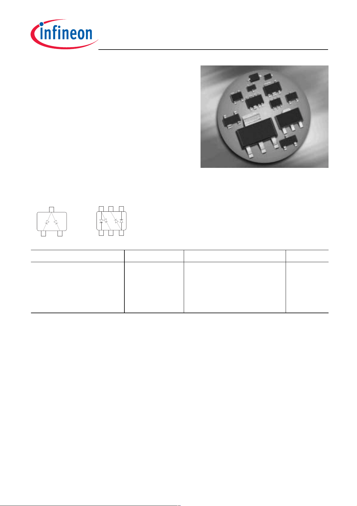
Silicon Switching Diode
• For high-speed switching applications
• Common anode configuration
• BAW56S / U: For orientation in reel see
package information below
BAW56...
BAW56
BAW56T
BAW56S
BAW56U
BAW56W
"
!
,
,
#$
, "
, !
,
,
!
Type Package Configuration Marking
BAW56
BAW56S
BAW56T
BAW56U
BAW56W
SOT23
SOT363
SC75
SC74
SOT323
common anode
double common anode
common anode
double common anode
common anode
A1s
A1s
A1
A1s
A1s
1
2006-01-13

Maximum Ratings at TA = 25°C, unless otherwise specified
BAW56...
Parameter
Diode reverse voltage V
Peak reverse voltage V
Forward current I
Non-repetitive peak surge forward current
t = 1 µs
t = 1 ms
t = 1 s, single
t = 1 s, double
Total power dissipation
T
BAW56,
BAW56S,
BAW56T,
BAW56U,
BAW56W,
≤ 28°C
S
T
≤ 85°C
S
T
≤ 104°C
S
T
≤ 90°C
S
T
≤ 103°C
S
Symbol Value Unit
R
RM
F
I
FSM
80 V
85
200 mA
A
4.5
1
0.5
0.75
P
tot
mW
330
250
250
250
250
Junction temperature T
Storage temperature T
Thermal Resistance
Parameter
Junction - soldering point1)
BAW56
BAW56S
BAW56T
BAW56U
BAW56W
1
For calculation of R
please refer to Application Note Thermal Resistance
thJA
j
stg
150 °C
-65 ... 150
Symbol Value Unit
R
thJS
K/W
360
260
185
240
190
2
2006-01-13
Electrical Characteristics at TA = 25°C, unless otherwise specified
Parameter
Symbol Values Unit
min. typ. max.
DC Characteristics
BAW56...
Breakdown voltage
= 100 µA
I
(BR)
Reverse current
= 70 V
V
R
= 25 V, TA = 150 °C
V
R
= 70 V, TA = 150 °C
V
R
Forward voltage
= 1 mA
I
F
= 10 mA
I
F
= 50 mA
I
F
= 100 mA
I
F
= 150 mA
I
F
AC Characteristics
Diode capacitance
V
= 0 V, f = 1 MHz
R
V
I
V
R
C
(BR)
F
T
85 - - V
-
-
-
-
-
-
-
-
-
-
-
-
-
-
-
-
0.15
30
50
715
855
1000
1200
1250
µA
mV
- - 2 pF
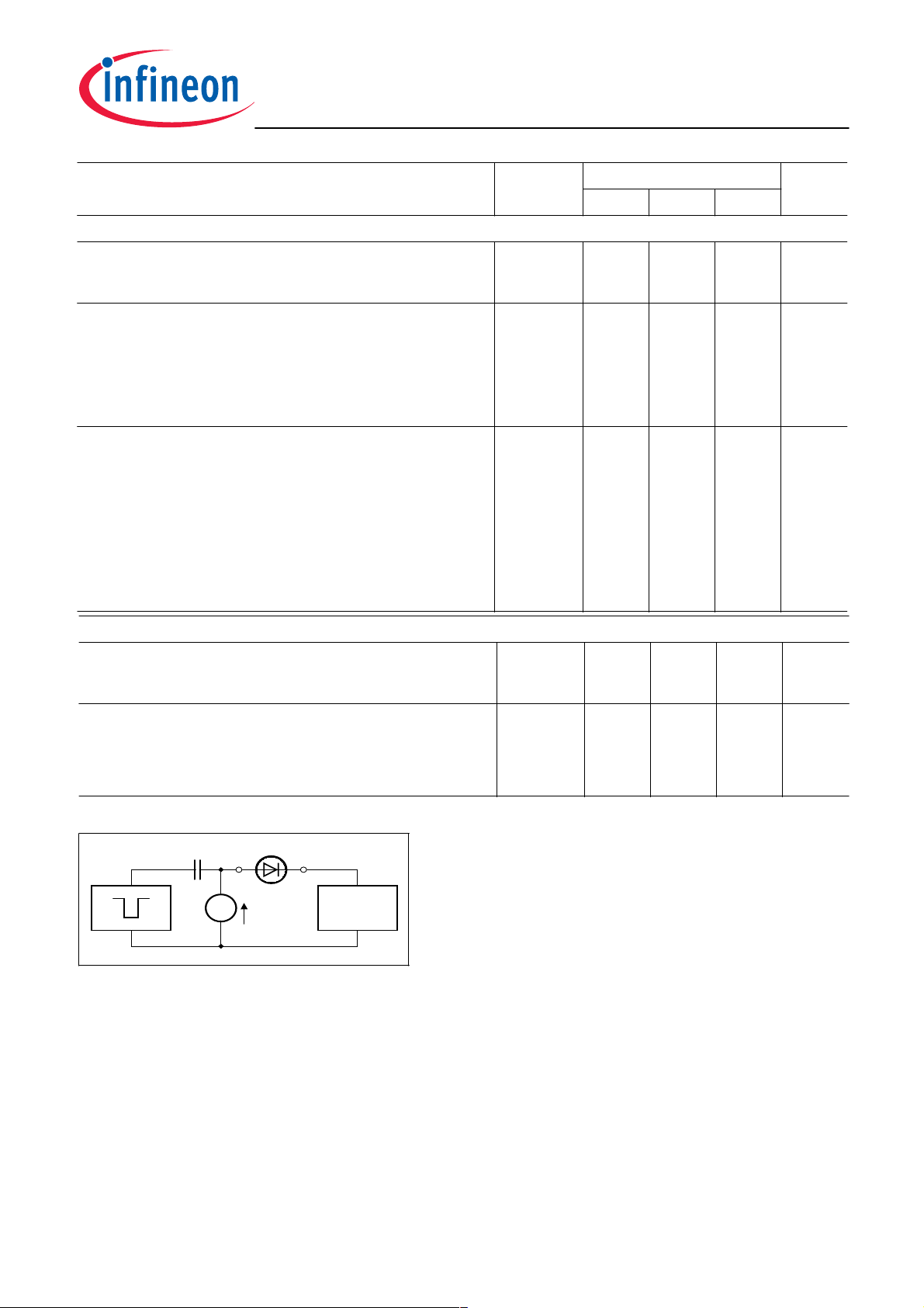
Reverse recovery time
I
= 10 mA, IR = 10 mA, measured at IR = 1mA,
F
R
= 100 Ω
L
Test circuit for reverse recovery time
D.U.T.
Pulse generator: tp = 100ns, D = 0.05, tr = 0.6ns,
R
Ι
F
Oscillograph
Oscillograph: R = 50Ω, t
EHN00019
t
rr
- - 4 ns
= 50Ω
i
= 0.35ns, C ≤ 1pF
r
3
2006-01-13
BAW56...
Reverse current IR = ƒ (TA)
V
= Parameter
R
5
10
nA
4
10
R
I
3
10
2
10
1
10
0 25 50 75 100
70 V
25 V
°C
Forward Voltage VF = ƒ (TA)
I
= Parameter
F
1.2
1
0.9
0.8
F
V
0.7
0.6
0.5
IF = 150mA
0.4
IF = 100mA
0.3
IF = 50mA
IF = 10mA
0.2
IF = 1mA
IF = 0,1mA
0.1
150
T
A
0
-40 -20 0 20 40 60 80 100 140
T
A
Forward current IF = ƒ (VF)
T
= 25°C
A
150
Ι
mA
F
100
50
0
typ max
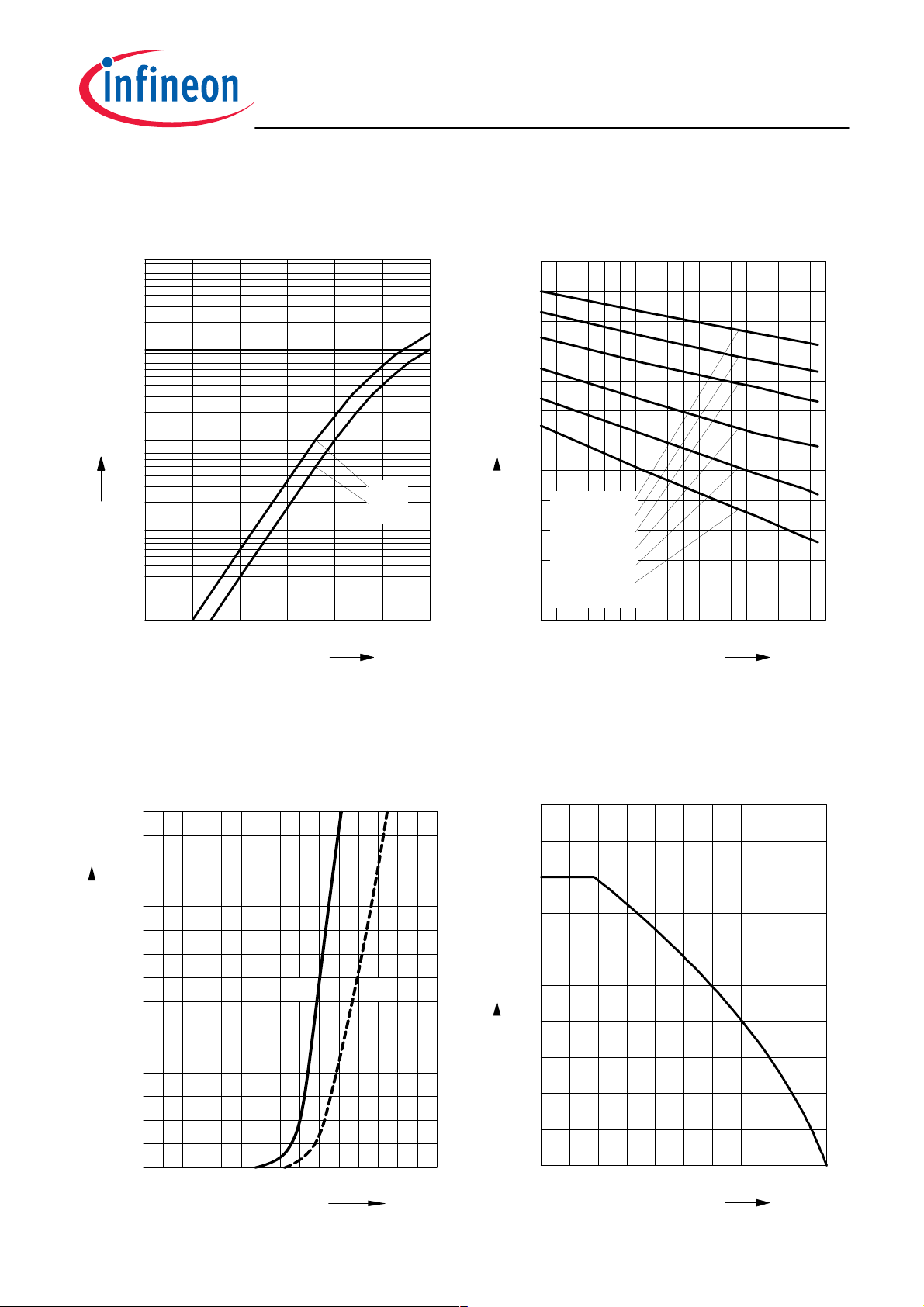
Forward current IF = ƒ (TS)
BAW56
EHB00091BAW 56
1.5V1.00.50
V
F
250
mA
200
175
F
I
150
125
100
75
50
25
0
0 15 30 45 60 75 90 105 120
°C
150
T
S
4
2006-01-13
BAW56...
i
Forward current IF = ƒ (TS)
BAW56S
250
mA
200
175
F
I
150
125
100
75
50
25
0
0 15 30 45 60 75 90 105 120
°C
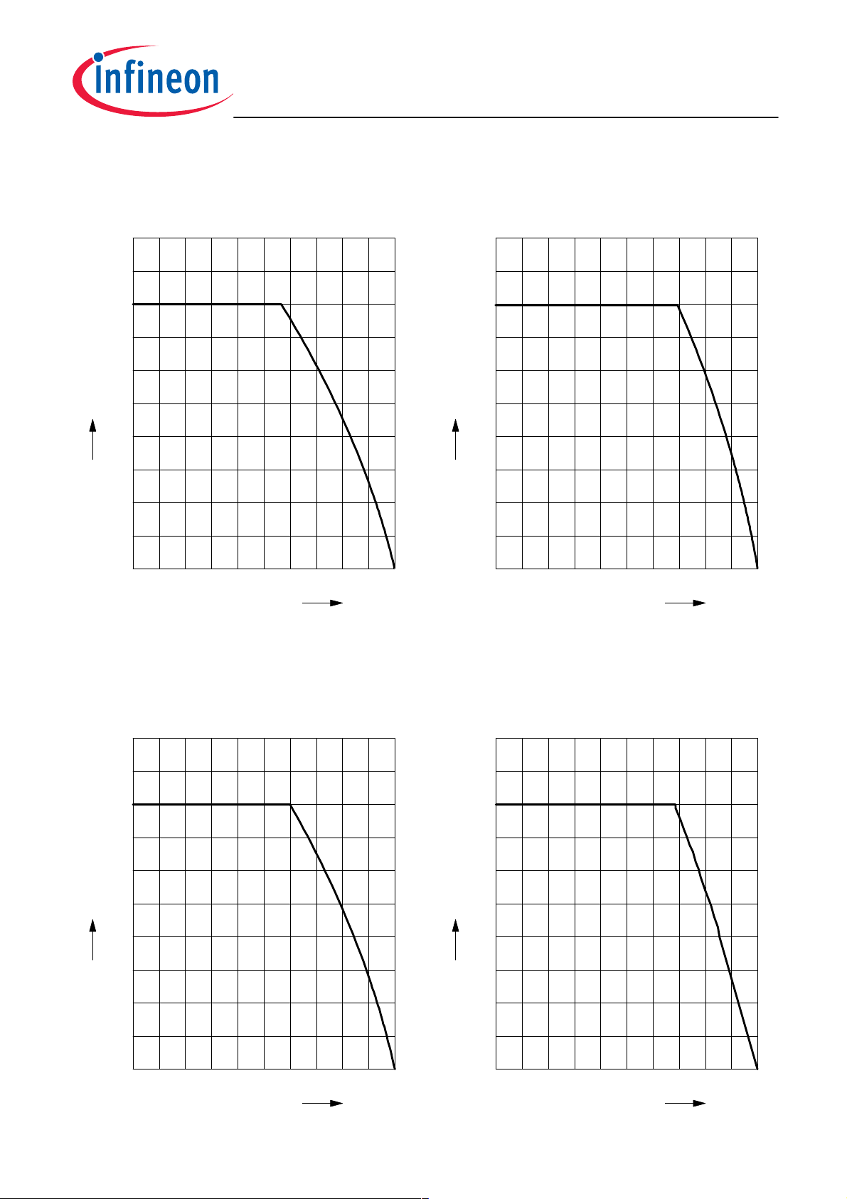
Forward current IF = ƒ (TS)
BAW56T
250
mA
200
175
F
I
150
125
100
75
50
25
Ke
150
T
S
0
0 15 30 45 60 75 90 105 120
°C
150
T
S
Forward current IF = ƒ (TS)
BAW56U
250
mA
200
175
F
I
150
125
100
75
50
25
0
0 15 30 45 60 75 90 105 120
T
°C
Forward current IF = ƒ (TS)
BAW56W
250
mA
200
175
F
I
150
125
100
75
50
25
150
S
0
0 15 30 45 60 75 90 105 120
T
°C
150
S
5
2006-01-13
 Loading...