

GB
50cm Free Standing Gas Cooker
English,1
ID50G
Contents
Warning,2
Introduction, 3
Installation, 4-8
Gas connection
Electrical connection
Adapting the cooker to di erent types of gas
Burner and Nozzle Speci cations
Safety Information, 9
Features, 10
Control Panel, 11
Use of hotplates, 12
Grilling, 13
Oven, 14
Oven cooking charts, 15
Top oven,16
Top Oven Cooking Chart, 17
Care and Cleaning, 18
Cooking Results Not Satisfactory?, 19
Something Wrong With Your Cooker?, 20
If it Still Won’t Work..., 21
Technical Characteristics, 22
Key Contacts, 24
You must read these instructions prior to using your
appliance and retain them for future use.
Operating Instructions
GB

WARNING: The appliance and its
accessible parts become hot during use.
Care should be taken to avoid touching
hea ng elements.
Children less than 8 years of
age shall be kept away unless
con nuously supervised.
This appliance can be used by children
aged from 8 years and above and
persons with reduced physical, sensory
or mental capabili es or lack of
experience and knowledge if they have
been given supervision or instruc on
concerning use of the appliance in a
safe way and understand the hazards
involved. Children shall not play with
the appliance. Cleaning and user
maintenance shall not be made by
children without supervision.
WARNING: Una ended cooking on a hob
with fat or oil can be dangerous and may
result in fi re.
NEVER try to ex nguish a fi re with
water, but switch off the appliance and
then cover fl ame e.g. with a lid or a fi re
blanket.
Do not use harsh abrasive cleaners or
sharp metal scrapers to clean the oven
door glass since they can scratch the
surface, which may result in sha ering of
the glass.
The internal surfaces of the
compartment (where present) may
become hot.
Never use steam cleaners or pressure
cleaners on the appliance.
Remove any liquid from
the lid before opening it.
Do not close the
glass cover (if present) when the gas
burners or electric hotplates are s ll hot.
WARNING: Ensure that the appliance is
switched off before replacing the lamp to
avoid the possibility of electric shock.
CAUTION: the use of inappropriate hob
guards can cause accidents.
!
When you place the rack inside, make
sure that the stop is directed upwards
and in the back of the cavity .
WARNING
GB
2
GB
3
Your new appliance is guaranteed* and will give lasting
service. This guarantee is only applicable if the appliance
has been installed in accordance with the installation
instructions detailed in this booklet.
To help make best use of your cooking equipment, please
read this booklet carefully.
The cooker is designed speci cally for domestic use and
responsibility will not be accepted for use in any other
installation.
! When the cooker is rst used an odour may be emitted,
this will cease after a period of use.
When rst using the cooker ensure that the room is well
ventilated (e.g. open a window or use an extractor fan)
and that persons who may be sensitive to the odour avoid
any fumes. It is suggested that any pets be removed from
the room until the smell has ceased. This odour is due to
temporary nish on oven liners and elements and also any
moisture absorbed by the insulation.
* The guarantee is subject to the provisions that the
appliance:
Introduction
a. Has been used solely in accordance with the Users
Instruction Book.
b. Has been properly connected to a suitable supply
voltage as stated on the rating plate attached to this
equipment.
c. Has not been subjected to misuse or accident or been
modi ed or repaired by any person other than the
authorised employee or agent.
d. Has been correctly installed.
1. This appliance is intended for nonprofessional use within
the home.
2. These instructions are only for those countries whose
symbols appear in the booklet and on the serial no. plate
of the appliance.
3. This owner’s manual is for a class 1 appliance (insulated)
or class 2, subclass 1 appliances (installed between two
cabinets.
! Keep the appliance clean, as a build up of
grease or fat from cooking can cause a re.

4
GB
The appliance must only be installed by a competent
person. In the UK, registered installers undertake to work to
safe and satisfactory standards.
Before moving your cooker check that it is cool, and switch
o at the cooker control unit. Movement of your cooker is
most easily achieved by lifting the front as follows:
Open the grill door su ciently to allow a comfortable grip
on the underside front edge of the oven roof, avoiding any
grill elements.
! Take care in moving the cooker as it is heavy. Take care to
ensure that any oor covering is not damaged. (see gure)
Splashplate optional, apply to
Parts Department (see Back Cover
for contact number.)
The following instructions
should be read by a quali ed
technician to ensure that the
appliance is installed, regulated
and technically serviced correctly
in compliance with current
regulations.
! remember to unplug the appliance from the mains before
regulating the appliance or carrying out any maintenance
work.
Positioning
! this unit may be installed and used only in permanently
ventilated rooms according to the British Standards Codes
Of Practice: B.S. 6172/B.S. 5440, Par. 2 and B.S. 6891 Current
Editions. The following requirements must be observed:
a. The cooker should not be installed in a bed sitting room
with a volume of less than 20m
3
. If it is installed in a
room of volume less than 5m
3
an air vent of e ective
area of 110cm2 is required, if it is installed in a room of
volume between 5m
3
and 10m3 a supplementary airvent
area of 50cm2 is required, if the volume exceeds 11m3
no airvent is required. However, if the room has a door or
a window which opens directly to the outside no air vent
is required even when the volume is between 5m
3
and
11m
3
.
b. During prolonged use of the appliance you may consider
it necessary to open a window to the outside to improve
ventilation.
c. If there are other fuel burning appliances in the same
room, B.S.5440 Part 2 Current Edition, should, be
consulted to determine the requisite air vent feet in
the plinth (900mm - 915mm). Adjust the feet by tilting
the cooker from the side. Then install the product into
position.
! This appliance must not be tted on a platform.
The cooker is designed to t between kitchen cabinets
spaced 500mm apart. The space either side need only be
su cient to allow withdrawal of the cooker for servicing. It
can be used with cabinets one side or both as well as in a
corner setting. It can also be used free-standing.
Adjacent side walls which project above hob level, must
not be nearer to the cooker than 150mm or 65mm (Fig. A)
and should be protected by heat resistant material. Any
overhanging surface or cooker hood should not be nearer
than 750mm. (Fig.A)
a. The cooker may be located in a kitchen, a kitchen/diner
or bed sitting room, but not in a bathroom or shower
room.
b. The hoods must be installed according to the
requirements in the hood handbook.
c. The wall in contact with the back of the cooker must be
of ameproof material.
d. The cooker is tted with a safety chain that must be
attached to a hook, secured to the wall behind the
appliance.
! some models can have their gas connection inverted.
It is important to make sure the safety chain is always
situated on the side which corresponds to the hose
holder (Fig. B).
Fig. A
Fig. B
Gas connection
The cooker should be connected to the gas-supply by
a gas sa e registered installer. During installation of this
product it is essential to t an approved gas tap to isolate
the supply from the appliance for the convenience of
any subsequent removal or servicing. Connection of the
appliance to the gas mains or liquid gas must be carried
out according to the prescribed regulation in force, and
Installation
Moving the Cooker
65 mm mi n
500 mm mi n
400 mm mi n400 mm mi n
750 mm mi n
Tall cupboard on the left hand
side of 50cm gas cooker
65 mm mi n
65 mm mi n
150 mm mi n
500 mm mi n
750 mm mi n
Tall cupboard on the right hand
side of 50cm gas cooker
f

GB
5
below.
WARNING - THIS APPLIANCE MUST BE EARTHED.
THE FOLLOWING OPERATIONS SHOULD BE CARRIED OUT
BY A QUALIFIED ELECTRICIAN.
Replacing the fuse
When replacing a faulty fuse, a 13 amp ASTA approved
fuse to BS 1362 should always be used, and the fuse cover
re- tted. If the fuse cover is lost, the plug must not be used
until a replacement is obtained.
Replacement fuse covers:
If a replacement fuse cover is tted, it must be of the
correct colour as indicated by the coloured marking or the
colour that is embossed in words on the base of the plug.
Replacements can be obtained directly from your nearest
Service Depot.
Removing the plug:
If your appliance has a non-rewireable moulded plug and
you should wish to remove it to add a cable extension or
to re-route the mains cable through partitions, units etc.,
please ensure that either:
• the plug is replaced by a fused 13 amp re-wireable plug
bearing the BSI mark of approval.
or:
• the mains cable is wired directly into a 13 amp cable
outlet, controlled by a switch, (in compliance with BS
5733) which is accessible without moving the appliance.
Please note: for appliances with a rating greater than 13
amp (eg: electric hob, double ovens and freestanding
electric cookers etc.) the mains cable must be wired into a
cooker output point with a rating of 45 amp. In this case the
cable is not supplied.
Disposing of the plug:
Ensure that before disposing of the plug itself, you make
the pins unusable so that it cannot be accidentally inserted
into a socket. Instructions for connecting cable to an
alternative plug:
! the wires in the mains lead are coloured in accordance
with the following code:
Green & Yellow - Earth
Blue - Neutral
Brown - Live
If the colours of the wires in the mains lead do not
correspond with the coloured markings identifying the
terminals in your plug, proceed as follows:
Connect Green & Yellow wire to terminal marked “E” or
or coloured Green or Green & Yellow.
Connect Brown wire to terminal marked “L” or coloured Red.
only after it is ascertained that it is adaptable to the type of
gas to be used. If not, follow the instructions indicated in
the paragraph headed “Adaptation to di erent gas types”.
On some models the gas supply can be connected on the
left or on the right, as necessary; to change the connection,
reverse the position of the hose holder with that of the cap
and replace the gasket (supplied with the appliance). In
the case of connection to liquid gas, by tank, use pressure
regulators that conform to the regulation in force. The gas
supply must be connected to the left of the appliance. Be
sure that the hose does not pass through the rear of the
cooker touching hot parts.
! make sure the supply pressure conforms with the
values shown in the table entitled “Caracteristics of
the burners and nozzles”. When the cooker is installed
between cabinets (recessed), the gas connection must be
e ected by an approved exible hose with bayonet tting
(BS669CurrentEdition). The gas inlet for the cookers is a
threaded G 1/2 gas female tting.
Connecting the gas supply
To make the connection, a exible hose should be used
corresponding to the current gas regulations which are:
• the hose must never be at any point in its lenght in
contact with the “hot” parts of the cooker;
• the hose must never be longer than 1,5 metre;
• the hose must not be subject to any tension or torsional
stress and it must not have any excessively narrow
curves or bottlenecks;
• the hose must be easy to inspect along its entire length
to check its condition;
• the hose must always be in good condition, never
attempt to repair.
! the installation must comply
with gas safety (installation and
use) regulations 1984. In all cases
for the above, by low, a quali ed,
gas sa e approved engineer must be
called for installation.
Electrical connection
Power supply voltage and frequency: 230-240V a.c. 50Hz.
! the supply cable must be positioned so that it never
reaches at any point a temperature 50°C higher than
the room temperature. The cable must be routed away
from the rear vents. Should you require it, you may use
a longer cable, however, you must ensure that the cable
supplied with the appliance is replaced by one of the same
speci cations in accordance with current standards and
legislation.
Your appliance is supplied with a 13 amp fused plug that
can be plugged into a 13 amp socket for immediate use.
Before using the appliance please read the instructions
HOT PARTS
600 mm
f

6
GB
Connect Blue wire to terminal marked “N” or coloured Black.
If a 13 amp plug (BS 1363) is used it must be tted with a 13
amp fuse. A 15 amp plug must be protected by a 15 amp
fuse, either in the plug or adaptor or at the distribution
board. If you are in any doubt about the electrical supply to
your machine, consult a quali ed electrician before use.
How to connect an alternative plug:
The wires in this mains lead are coloured in accordance
with the following code:
BLUE “NEUTRAL” (“N”)
BROWN “LIVE” (“L”)
GREEN AND YELLOW
Disposing of the appliance
When disposing of the appliance please remove the plug
by cutting the mains cable as close as possible to the plug
body and dispose of it as described above.
Adapting the cooker to di erent types of gas
In order to adapt the cooker to a di erent type of gas with
respect to the gas for which it was produced (indicated on
the label attached to the lid), follow these steps:
a) replace the hose holder mounted on the appliance with
that supplied in the bag of “cooker accessories”.
b) Replacing the burner nozzles on the hob:
• remove the grids and slide the burners from their
housings;
• unscrew the nozzles using a 7
mm socket spanner, and replace
them with nozzles for the new
type of gas (see table 1 “Burner
and nozzle characteristics”).
• replace all the components by
repeating the steps in reverse
order.
c) Minimum regulation of the hob burners:
• turn the tap to minimum;
• remove the knob and adjust the regulation screw, which
is positioned in or next to the tap pin, until the ame is
small but steady.
! in the case of liquid gas, the regulation screw must be
screwed in to the bottom.
• check that the ame does not turn o when you turn the
tap quickly from high to low.
d) Regulating the primary air of the burners:
The primary air of the burners requires no regulation.
Adapting to di erent types of gas
In order to adapt the oven to a di erent type of gas with
respect to the gas for which it was manufactured (indicated
on the label), follow these simple steps:
a) Replacing the oven burner nozzle
• open the oven door fully
• pull out the sliding oven
bottom
V
V
Z
• Pry the xing tab “V” and remove the oven burner
• Unscrew the oven burner nozzle using the socket
spanner for the nozzles “Z”, or a 7 mm socket spanner,
and replace it with a nozzle suited to the new type of gas
(see Table 1).
Take particular care handling the spark plug wires and
the thermocouple pipes.
• Replace all the parts, following the steps described
above in the reverse order.
b) Minimum regulation of the gas oven burner with
thermostat:
• light the burner as described in the paragraph “the oven
knob” of the instruction booklet.
• turn the knob to Max for about 10 minutes and then turn
the knob to the Min setting;
• remove the knob;
• regulate the screw positioned outside the thermostat
pin until the ame is small but steady.
! in the case of liquid gas, the regulation screw must be
screwed in to the bottom.
GREEN &
YELLOW
BROWN
BLUE
13 amp fuse
CROSS-BAR
CORD GRIP
unscrew the two screws and take off the shield
protecting the burner (in main oven burner only).
“EARTH” (“E”)
WARNING.
If the electric supply fails to this appliance you must
not use the grill or ovens.
WARNING.
If the electric supply fails to this appliance you must
not use the grill or ovens.

GB
7
• check that the burner does not turn o when you turn
the knob from Max to Min and and when you open and
close the oven door quickly.
Adapting the gas grill to di erent types of gas
Replacing the nozzle of the grill burner:
• remove the screw and then slide out the grill burner “V”
(see Figure);
• unscrew the grill burner nozzle using the special socket
spanner for the nozzles (see Figure) or better still a 7mm
socket spanner; replace the nozzle with a nozzle for the
new type of gas (see table 1).
Important
On completion of the operation, replace the old rating
sticker with one indicating the new type of gas used. This
sticker is available from our Service Centres.
Note
Should the pressure of the gas used be di erent (or
vary) from the recommended pressure, it is necessary
to t a suitable pressure regulator onto the inlet pipe in
compliance with current National Regulations relative to
“regulators for channelled gas”.
V
I
8
GB
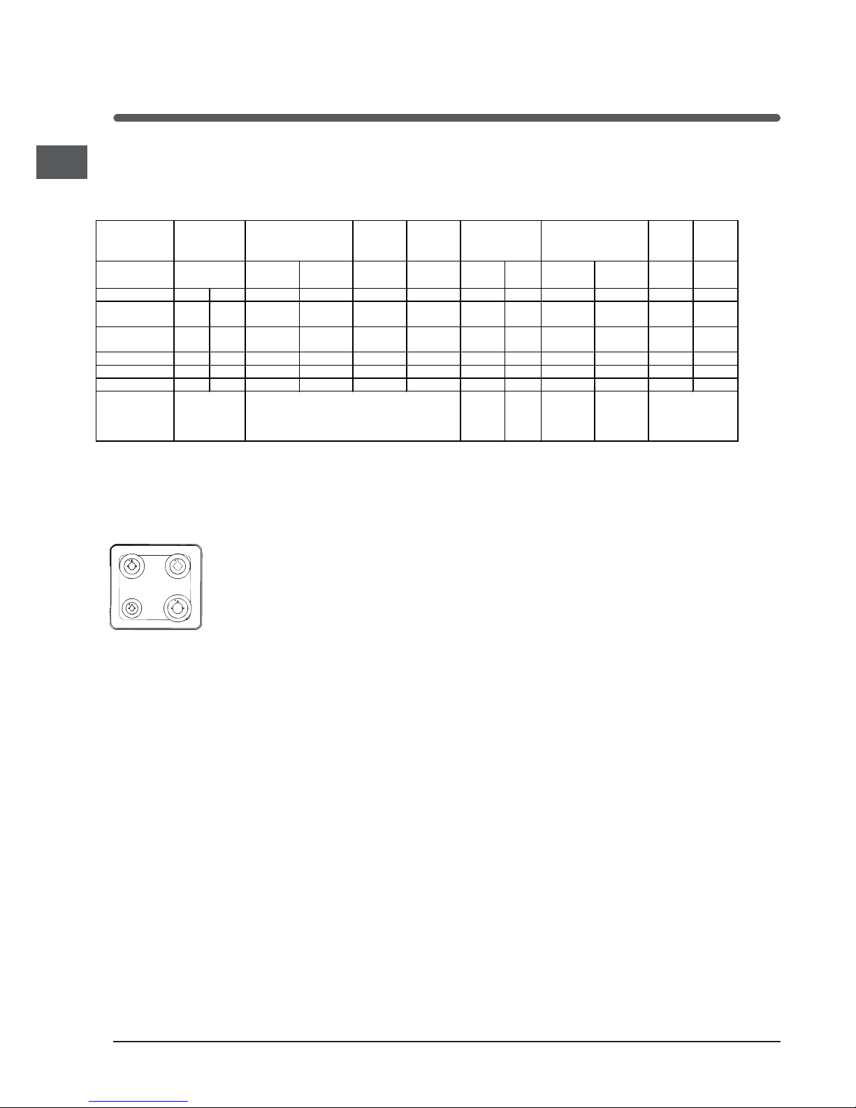
Burner and Nozzle Speci cations
*At 15’C and 1013 mbar- dry gas
** Propane – P.C.S = 50,37 MJ/Kg
*** Butane – P.C.S = 49,47 MJ/Kg
Natural – P.C.S = 37,78 MJ/m
3
S
S
R
A
ID50G
Burner Diameter
(mm)
Thermal Power kW
(p.c.s.*)
By-pass
1/100
(mm)
Nozzle
1/100
(mm)
Flow*
(g/h)
Thermal Power kW
(p.c.s.*)
Nozzle
1/100
(mm)
Flow*
(l/h)
Nominal Reduced *** ** Nominal Reduced
Fast (Large) R 100 94 3,0 0,7 41 87 189 186 3,0 0,7 128 286
Semi Fast
(Medium) S
75 69 1,9 0,4 30 70 138 136 1,9 0,4 104 181
Auxiliary
(Small) A
51 46 1,0 0,4 30 52 73 71 1,0 0,4 76 95
Main Oven - - 2,6 0,6 34 71 189 186 2,6 0,6 115 248
Grill - - 2,3 2,0 - 75 167 164 2,3 1,3 114 219
Top oven - - 2,0 0,6 34 66 145 143 2,0 0,6 104 (X) 190
Supply
Pressures
(mbar)
Nominal
Minimum
Maximum
28-30
20
35
37
25
45
20
17
25
 Loading...