


DISHWASHER
DFG 261
Operating Instructions
English,1
AU
Contents
Installation, 2-3
Positioning and levelling
Connecting the water and electricity supplies
Advice regarding the fi rst wash cycle
Technical data
Description of the appliance, 4
Overall view
Control panel
Loading the racks, 5
Lower rack
Cutlery basket
Upper rack
Start-up and use, 6-7
Starting the dishwasher
Measuring out the detergent
Wash options
Wash cycles, 8
Table of wash cycles
Rinse aid and refi ned salt, 9
Measuring out the rinse aid
Measuring out the refi ned salt
Care and maintenance, 10
Shutting off the water and electricity supplies
Cleaning the dishwasher
Preventing unpleasant odours
Cleaning the sprayer arms
Cleaning the water inlet fi lter
Cleaning the fi lters
Leaving the machine unused for extended periods
Precautions and advice, 11
General safety
Disposal
Saving energy and respecting the environment
Troubleshooting, 12
2
AU
Installation
Keep this instructions manual in a safe place for future
reference. If the appliance is sold, given away or moved, please
ensure the manual is kept with the machine, so that the new
owner may benefi t from the advice contained within it.
Please read this instruction manual carefully: it contains
important information regarding the safe installation, use and
maintenance of the appliance.
If the appliance must be moved at any time, keep it in an
upright position; if absolutely necessary, it may be tilted onto its
back.
Positioning and levelling
1. Remove the appliance from all packaging and check that it
has not been damaged during transportation.
If it has been damaged, contact the retailer and do not proceed
any further with the installation process.
2. Check the dishwasher by placing it so that its sides or back
panel are in contact with the adjacent cabinets or even with
the wall. This appliance can also be recessed under a single
worktop * (see the Assembly instruction sheet).
3. Position the dishwasher on a level and sturdy fl oor. If the
fl oor is uneven, the front feet of the appliance may be adjusted
until it reaches a horizontal position. If the appliance is levelled
correctly, it will be more stable and much less likely to move or
cause vibrations and noise while it is operating.
4*. Adjust the height of the rear foot from the front of the
appliance* on the central lower part of the dishwasher, turning
a hexagonal spanner (red color) with an opening of 8 mm in a
clockwise direction to increase the height or in an anticlockwise
direction to decrease the height.
Connecting the water and electricity
supplies
Connection to the water and electricity supplies should only
be performed by a qualifi ed technician.
The dishwasher should not stand on top of the water hoses
or the electricity supply cable.
The appliance must be connected to the water supply
network using new hoses.
Never use old or second hand hose sets. Do not reuse hose
sets from any previously installed dishwasher.
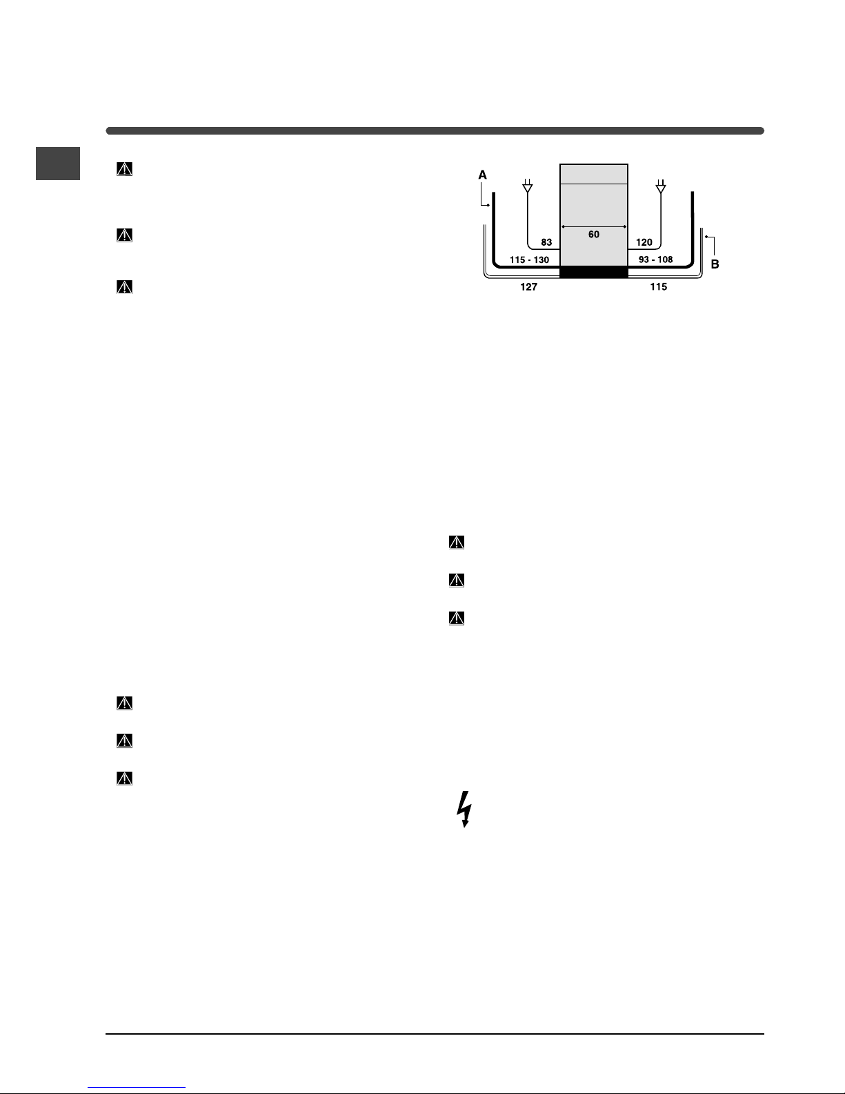
The water inlet (A) and outlet (B) hoses and the electricity
supply cable may be positioned towards the right or the left in
order to achieve the best possible installation (see fi gure).
Connecting the water inlet hose
To a suitable cold water connection point: before attaching
the hose, run the water until it is perfectly clear so that any
impurities that may be present in the water do not clog the
appliance; after performing this operation, screw the inlet
hose tightly onto a tap with a ¾ gas threaded connection.
To a suitable hot water connection point: your dishwasher
may be supplied with hot water from the mains supply (if
you have a central heating system with radiators) provided
that it does not exceed a temperature of 60°C.
Screw the hose to the tap as described for connection to a
cold water supply.
It the inlet hose is not long enough, contact a specialist
store or an authorised technician (see Assistance).
The water pressure must be within the values indicated in
the Technical data table (see adjacent information).
The hose should not be bent or compressed.
Anti-fl ooding protection
To ensure fl oods do not occur, the dishwasher:
- is provided with a special system which blocks the water
supply in the event of anomalies or leaks from inside the
appliance.
Some models are also equipped with the supplementary
safety device New Acqua Stop*, which guarantees antifl ooding protection even in the event of a supply hose rupture.
WARNING: HAZARDOUS VOLTAGE!
Under no circumstances should the water inlet hose be cut as
it contains live electrical parts.
* Only available in selected models.
AU
3
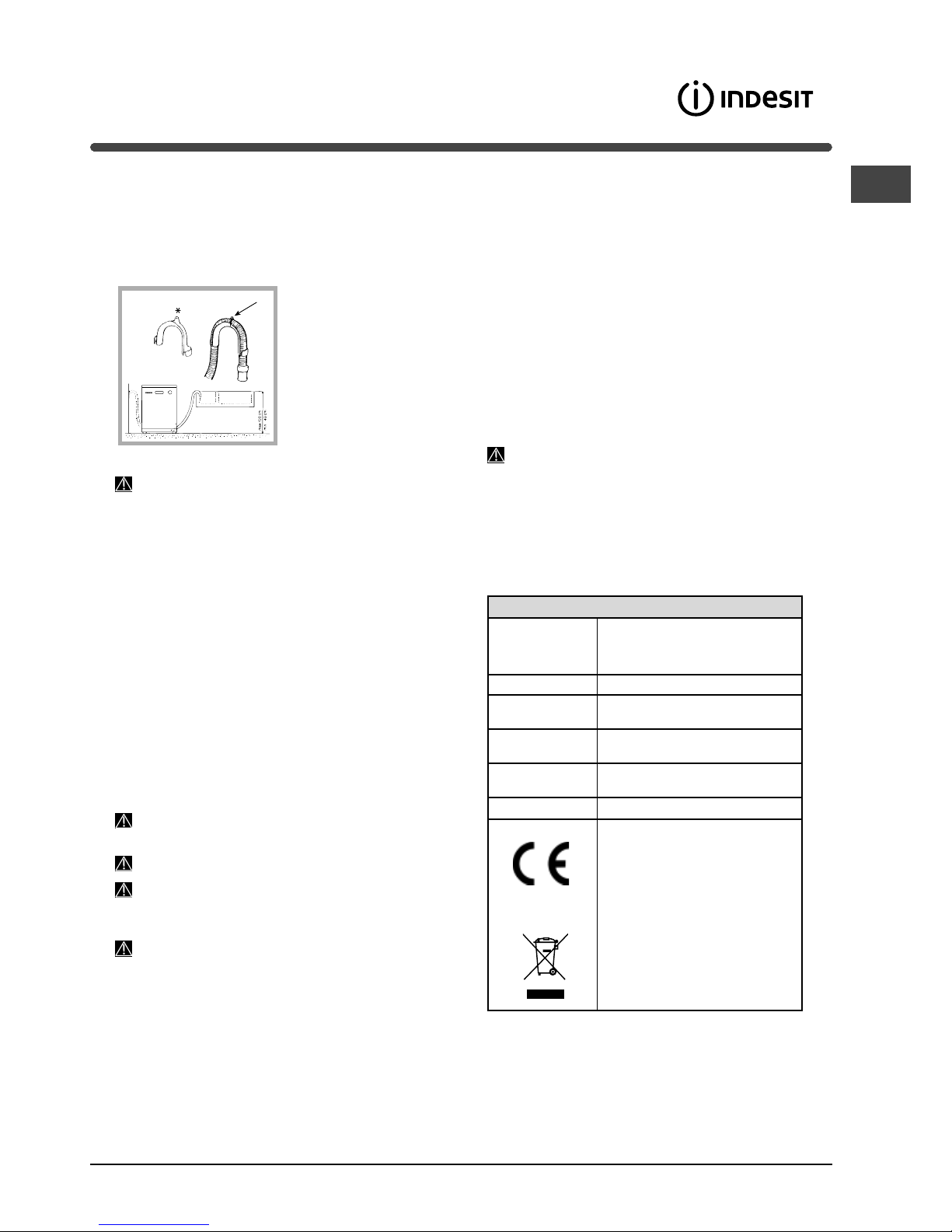
Connecting the water outlet hose
Connect the outlet hose (without bending it) to a drain duct with
a minimum diameter of 4 cm. Alternatively, rest it over a sink
or tub; the free end of the hose should not remain immersed in
water.
The specialist plastic elbow*
makes it easier to fi nd the best
layout: fi x the elbow to the wall
securely in order to prevent the
outlet hose from moving and
spilling the dirty water.
The part of the hose marked
with the letter A should be
between 40 and 100 cm above
the ground (see fi gure).
We advise against the use of hose extensions.
Electrical connection
Before inserting the plug into the electrical socket, make sure
that:
The socket is earthed and complies with current regulations.
The socket can withstand the maximum load of the appli-
ance, which is indicated on the data plate located on the
inside of the door (see chapter entitled Description of the
appliance).
The power supply voltage falls within the values indicated on
the data plate on the inside of the door.
The socket is compatible with the plug of the appliance. If
this is not the case, ask an authorised technician to replace
the plug (see Assistance); do not use extension cables or
multiple sockets.
Once the appliance has been installed, the power supply
cable and the electrical socket should be easily accessible.
The cable should not be bent or compressed.
If the power supply cable is damaged, it must be replaced
by the manufacturer or its Technical Assistance Service in order
to prevent all potential hazards. (See Assistance)
The Company shall not be held responsible for any
incidents that occur if these regulations are not observed.
Anti-condensation strip*
After installing the dishwasher, open the door and stick the
adhesive transparent strip under the wooden shelf in order to
protect it from any condensation which may form.
Advice regarding the fi rst wash cycle
After the appliance has been installed, immediately before
running the fi rst wash cycle, completely fi ll the salt dispenser
with water and add only then approximately 1 kg of salt (see
chapter entitled Rinse aid and refi ned salt). The water may
overfl ow: this is normal and is not a cause for concern. Select
the water hardness value (see chapter entitled Rinse aid and
refi ned salt). – After the salt has been poured into the machine,
the LOW SALT indicator light* switches off.
If the salt container is not fi lled, the water softener and the
heating element may be damaged as a result.
A
Technical Data
Dimensions width 60 cm
height 85 cm
depth 60cm
Capacity 14 standard place settings
Water supply
pressure
0.05 - 1 MPa (0.5-10 bar)
7.25-145 psi
Power supply
voltage
See appliance data plate
Total absorbed
power
See appliance data plate
Fuse See appliance data plate
This dishwasher conforms to the
following European Community
Directives:
-2006/95/CE dated 16/01/2007 (Low
Voltage) and subsequent modifi ca-
tions
-89/336/EEC dated 03/05/89
(Electromagnetic Compatibility) and
subsequent modifi cations
-97/17/EC (Labelling)
-2002/96/ CE Waste Electrical and
Electronic Equipment (WEEE)
* Only available in selected models.
4
AU
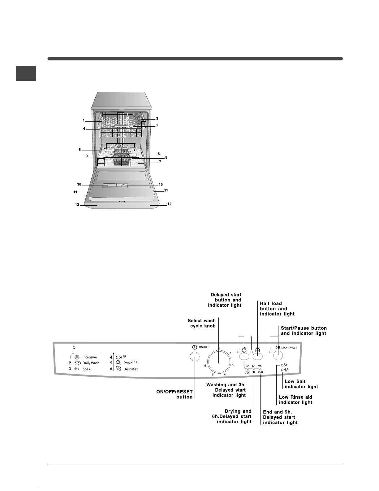
Description of the
appliance
Overall view
1. Upper rack
2. Upper sprayer arm
3. Tip-up compartments
4. Rack height adjuster
5. Lower rack
6. Lower sprayer arm
7. Cutlery basket
8. Washing fi lter
9. Salt dispenser
10. Detergent and rinse aid dispensers
11. Data plate
12. Control Panel***
Control Panel
***Only in completely built-in models
* Only available in selected models
The number and type of wash cycles and options may vary depending on the dishwasher model
 Loading...