

Page 1
PA-STEREO-VERSTÄRKER
PA STEREO AMPLIFIER
AMPLIFICATEUR STEREO PA
AMPLIFICATORE STEREO PA
STA-700 Best.-Nr. 24.4120
STA-700
BEDIENUNGSANLEITUNG • INSTRUCTION MANUAL • MODE D’EMPLOI • ISTRUZIONI PER L’USO
MANUAL DE INSTRUCCIONES • INSTRUKCJA OBSŁUGI • VEILIGHEIDSVOORSCHRIFTEN
SIKKERHEDSOPLYSNINGER • SÄKERHETSFÖRESKRIFTER • TURVALLISUUDESTA
800
W
PRO POWER AMPLIFIER
CLIP CLIP
PROTECT
POWER
–
∞
L-CH
–
0
0
∞
R-CH
POWER
Page 2

2
wwwwww..iimmggssttaaggeelliinnee..ccoomm
Voordat u inschakelt ...
Wij wensen u veel plezier met uw nieuw toestel van “img
Stage Line”. Lees de veiligheidsvoorschriften, alvorens
het toestel in gebruik te nemen. Door de veiligheidsvoorschriften op te volgen zal een slechte werking vermeden
worden, en zal een eventueel letsel aan uzelf en schade
aan uw toestel tengevolge van onzorgvuldig gebruik
worden voorkomen.
U vindt de veiligheidsvoorschriften op pagina 10.
Bevor Sie einschalten ...
Wir wünschen Ihnen viel Spaß mit Ihrem neuen Gerät von
„img Stage Line“. Dabei soll Ihnen diese Bedienungsanleitung helfen, alle Funktionsmöglichkeiten kennen zu lernen. Die Beachtung der Anleitung vermeidet außerdem
Fehlbedienungen und schützt Sie und Ihr Gerät vor eventuellen Schäden durch unsachgemäßen Gebrauch.
Den deutschen Text finden Sie auf den Seiten 4–5.
Before you switch on ...
We wish you much pleasure with your new “img Stage
Line” unit. With these operating instructions you will be
able to get to know all functions of the unit. By following
these instructions false operations will be avoided, and
possible damage to yourself and your unit due to improper use will be prevented.
You will find the English text on the pages 4 – 5.
D
A
CH
GB
Przed uruchomieniem ...
Życzymy zadowolenia z nowego produktu “img Stage
Line”. Dzięki tej instrukcji obsługi będą Państwo w
stanie poznać wszystkie funkcje tego urządzenia.
Stosując się do instrukcji unikną Państwo błędów i
ewentualnego uszkodzenia urządzenia na skutek nieprawidłowego użytkowania.
Tekst polski znajduje się na stronach 8 – 9.
PL
B
NL
Antes de cualquier instalación ...
Tenemos de agradecerle el haber adquirido un aparato
“img Stage Line” y le deseamos un agradable uso. Este
manual quiere ayudarle a conocer las multiples facetas
de este aparato. La observación de las instrucciones
evita operaciones erróneas y protege Vd. y vuestro aparato contra todo daño posible por cualquier uso inadecuado.
La versión española se encuentra en las páginas 8– 9.
Inden De tænder for apparatet ...
Vi ønsker Dem god fornøjelse med Deres nye “img
Stage Line” apparat. Læs oplysningerne for en sikker
brug af apparatet før ibrugtagning. Følg sikkerhedsoplysningerne for at undgå forkert betjening og for at beskytte Dem og Deres apparat mod skade på grund af forkert brug.
Sikkerhedsoplysningerne finder De på side 10.
E
DK
Förskrift
Vi önskar dig mycket nöje med din nya enhet från “img
Stage Line”. Läs gärna säkerhetsinstruktionerna innan
du använder enheten. Genom att följa säkerhetsinstruktionerna kan många problem undvikas, vilket annars kan
skada enheten.
Du finner säkerhetsinstruktionerna på sidan 10.
S FIN
Avant toute mise en service ...
Nous vous remercions d’avoir choisi un appareil “img
Stage Line” et vous souhaitons beaucoup de plaisir à
l’utiliser. Cette notice a pour objectif de vous aider à
mieux connaître les multiples facettes de l’appareil. En
outre, en respectant les conseils donnés, vous éviterez
toute mauvaise manipulation de sorte que vous-même et
votre appareil soient protégés de tout dommage.
La version française se trouve pages 6– 7.
Prima di accendere ...
Vi auguriamo buon divertimento con il Vostro nuovo
apparecchio “img Stage Line”. Le istruzioni per l’uso Vi
possono aiutare a conoscere tutte le possibili funzioni. E
rispettando quanto spiegato nelle istruzioni, evitate di
commettere degli errori, e così proteggete Voi stessi, ma
anche l’apparecchio, da eventuali rischi per uso improprio.
Il testo italiano lo potete trovare alle pagine 6– 7.
F
B
CH
I
Ennen virran kytkemistä ...
T oivomme, että uusi “img Stage Line”-laitteesi tuo sinulle
paljon iloa ja hyötyä. Ole hyvä ja lue käyttöohjeet ennen
laitteen käyttöönottoa. Luettuasi käyttöohjeet voit käyttää laitetta turvallisesti ja vältyt laitteen väärinkäytöltä.
Käyttöohjeet löydät sivulta 11.
Page 3
3
12 345 6 7
8
➁
9101112 13 14 15
INPUTS
LEFT
RIGHT
LIFT GND
OUTPUTS
(4Ω min.)
RIGHT
GND
SIGNAL
R
L
1+1–2+
2–
LEFT
➃➄
➅➆
➇
➂
L-CH
–
∞
0
R-CH
–
∞
0
PROTECT
POWER
POWER
CLIP CLIP
STA-700
800
W
PRO POWER AMPLIFIER
➀
2+
2
-
1
-
1+
+
-
4 Ω, 275WRMS
8 Ω, 200 WRMS
+
8 Ω
-
138 WRMS
+
8 Ω
-
138 WRMS
+
8 Ω
-
50 WRMS
+
8 Ω
-
50 WRMS
+
8 Ω
-
50 WRMS
+
8 Ω
-
50 WRMS
+
-
+
-
4 Ω, 100 WRMS
4 Ω, 100 WRMS
+
4 Ω
-
69 WRMS
+
4 Ω
-
69 WRMS
+
4 Ω
-
69 WRMS
+
4 Ω
-
69 WRMS
Page 4
Bitte klappen Sie die Seite 3 heraus. Sie sehen
dann immer die beschriebenen Bedienelemente
und Anschlüsse.
1 Übersicht der Bedienelemente und
Anschlüsse
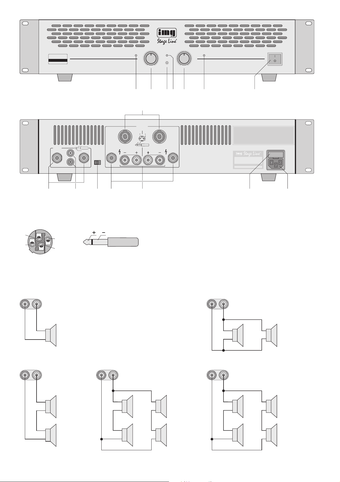
1.1 Frontseite
1 LED CLIP leuchtet bei Übersteuerung des linken
Kanals und bei Kurzschluss des linken Ausgangs
2 Lautstärkeregler für den linken Kanal
3 Betriebsanzeige POWER
4 LED PROTECT leuchtet bei aktivierter Schutz-
schaltung: ca. 1 Sekunde lang nach dem Einschalten bis zur Freischaltung der Lautsprecherausgänge und wenn der Verstärker überhitzt ist
5 Lautstärkeregler für den rechten Kanal
6 LED CLIP leuchtet bei Übersteuerung des rech-
ten Kanals und bei Kurzschluss des rechten Ausgangs
7 Ein-/Ausschalter POWER
1.2 Rückseite
8 Lautsprecheranschlüsse OUTPUTS als “SPEA-
KER”-Buchsen
9 Eingangsbuchsen INPUTS als 6,3-mm-Klinken-
buchsen für Geräte mit Line-Pegel (z.B. Mischpult, Vorverstärker)
10 Eingangsbuchsen INPUTS als Cinchbuchsen für
Geräte mit Line-Pegel
11 Groundlift-Schalter
Position GND: Signalmasse und Gehäusemasse
sind verbunden
Position LIFT: Signalmasse und Gehäusemasse
sind getrennt
12 Lautsprecheranschlüsse OUTPUTS als 6,3-mm-
Klinkenbuchsen
13 Lautsprecheranschlüsse OUTPUTS als Schraub-
klemmen mit 4-mm-Bananenbuchsen
14 Sicherungshalter; eine durchgebrannte Siche-
rung nur durch eine gleichen Typs ersetzen
15 Netzbuchse zur Stromversorgung an 230 V~/
50Hz
2 Hinweise für den sicheren Gebrauch
Dieses Gerät entspricht der Richtlinie für elektromagnetische Verträglichkeit 89/ 336/ EWG und der
Niederspannungsrichtlinie 73/23/EWG.
Das Gerät wird mit lebensgefährlicher Netzspannung (230V~) versorgt. Nehmen Sie
deshalb nie selbst Eingriffe im Gerät vor.
Durch unsachgemäßes Vorgehen besteht
die Gefahr eines elektrischen Schlages.
Außerdem erlischt beim Öffnen des Gerätes
jeglicher Garantieanspruch.
Vorsicht! Im Betrieb liegt an den Lautsprecheranschlüssen berührungsgefährliche
Spannung an.
Alle Anschlüsse nur bei ausgeschaltetem
Gerät vornehmen bzw. verändern.
Beachten Sie auch unbedingt die folgenden Punkte:
●
Das Gerät ist nur zur Verwendung im Innenbereich geeignet. Schützen Sie es vor Tropf- und
Spritzwasser, hoher Luftfeuchtigkeit und Hitze
(zulässiger Einsatztemperaturbereich 0– 40°C).
●
Stellen Sie keine mit Flüssigkeit gefüllten Gefäße,
z.B. Trinkgläser, auf das Gerät.
●
Die in dem Gerät entstehende Wärme muss durch
Luftzirkulation abgegeben werden. Decken sie darum die Lüftungsschlitze des Gehäuses nicht ab.
●
Stecken Sie nichts durch die Lüftungsschlitze! Dabei kann es zu einem elektrischen Schlag kommen.
●
Nehmen Sie das Gerät nicht in Betrieb bzw. ziehen
Sie sofort den Netzstecker aus der Steckdose:
1. wenn sichtbare Schäden am Gerät oder an der
Netzanschlussleitung vorhanden sind,
2. wenn nach einem Sturz oder Ähnlichem der
Verdacht auf einen Defekt besteht,
3. wenn Funktionsstörungen auftreten.
Lassen Sie das Gerät in jedem Fall in einer Fachwerkstatt reparieren.
●
Ziehen Sie den Netzstecker nie am Kabel aus der
Steckdose, fassen Sie immer am Stecker an.
●
Verwenden Sie für die Reinigung nur ein trockenes,
weiches Tuch, niemals W asser oder Chemikalien.
●
Wird das Gerät zweckentfremdet, nicht richtig angeschlossen, falsch bedient oder nicht fachgerecht
repariert, kann keine Haftung für daraus resultierende Sach- oder Personenschäden und keine
Garantie für das Gerät übernommen werden.
3 Einsatzmöglichkeiten
Dieser PA-Stereo-Verstärker ist speziell für den Einsatz auf der Bühne und in der Disco konzipiert.
Umfangreiche Schutzschaltungen schützen den
Verstärker und die angeschlossenen Lautsprecher.
4 Aufstellmöglichkeiten
Der Verstärker ist für den Einschub in ein Rack
(482mm/19") vorgesehen, kann aber auch als
Tischgerät verwendet werden. In jedem Fall muss
Luft ungehindert durch alle Lüftungsschlitze strömen können, damit eine ausreichende Kühlung
gewährleistet ist.
4.1 Rackeinbau
Für die Rackmontage werden 2 HE (Höheneinheiten) = 89mm benötigt. Dabei sollte jedoch ober- und
unterhalb des Verstärkers zusätzlich Platz frei bleiben, damit eine ausreichende Belüftung sichergestellt ist.
Damit das Rack nicht kopflastig wird, muss der
Verstärker im unteren Bereich des Racks eingeschoben werden. Für eine sichere Befestigung
reicht die Frontplatte allein nicht aus. Zusätzlich
müssen Seitenschienen oder eine Bodenplatte das
Gerät halten.
Soll das Gerät endgültig aus dem Betrieb genommen werden, übergeben Sie
es zur umweltgerechten Entsorgung
einem örtlichen Recyclingbetrieb.
B
Please unfold page 3. Then you can always see
the operating elements described.
1 Operating Elements and Connections
1.1 Front panel
1 LED CLIP lights up if the left channel is overload-
ed and in case of short circuit of the left output
2 Volume control for the left channel
3 LED POWER
4 LED PROTECT lights up with activated protec-
tive circuit: approx. 1 second after switching-on
until the speaker outputs are ready for operation
and if the amplifier is overheated
5 Volume control for the right channel
6 LED CLIP lights up with overload of the right chan-
nel and in case of short circuit of the right output
7 POWER switch
1.2 Rear panel
8 Speaker connections OUTPUTS as “SPEAKER”
jacks
9 Jacks INPUTS as 6.3 mm jacks for units with line
level (e.g. mixer, preamplifier)
10 Jacks INPUTS as phono jacks for units with line
level
11 Ground lift switch
position GND: signal ground and housing ground
are connected
position LIFT: signal ground and housing ground
are separated
12 Speaker connections OUTPUTS as 6.3mm jacks
13 Speaker connections OUTPUTS as screw termi-
nals with 4mm banana jacks
14 Fuse holder; only replace a blown fuse by one of
the same type
15 Mains jack for power supply for connection to
230V~/50Hz
2 Safety Notes
This unit corresponds to the directive 89/336 / EEC
for electromagnetic compatibility and to the low voltage directive 73/23/EEC.
This unit uses hazardous mains voltage
(230V~). To prevent a shock hazard, do not
open the cabinet. Leave servicing to authorized, skilled personnel only. Furthermore,
any guarantee claim expires if the unit has
been opened.
Caution! There is a hazard of contact at the
speaker connections with a dangerous voltage during operation.
All connections must only be carried out or
changed with the unit switched off.
It is essential to observe the following items:
●
The unit is suitable for indoor use only. Protect it
against dripping water and splash water, high
humidity, and heat (admissible ambient temperature range 0– 40°C).
●
Do not place any vessel filled with liquid, e. g. a
drinking glass, on the unit.
●
The heat generated in the unit has to be dissipated by air circulation. Therefore, the air vents of
the cabinet must not be covered.
●
Do not insert anything into the air vents! This can
result in an electric shock.
●
Do not set the unit into operation, and immediately
disconnect the mains plug from the mains socket if
1. there is visible damage to the unit or to the
mains cable,
2. a defect might have occurred after a drop or
similar accident,
3. there are malfunctions.
The unit must in any case be repaired by skilled
personnel.
●
Never pull the mains cable to disconnect the mains
plug from the mains socket, always seize the plug.
●
For cleaning only use a dry, soft cloth, by no
means chemicals or water.
●
No guarantee claims for the unit and no liability for
any resulting personal damage or material damage will be accepted if the unit is used for purpos-
es other than originally intended, if it is not correctly connected or operated, or not repaired in an
expert way.
●
Important for U.K. Customers!
The wires in the mains lead are coloured in accordance with the following code:
green/yellow = earth
blue = neutral
brown = live
As the colours of the wires in the mains lead of this
appliance may not correspond with the coloured
markings identifying the terminals in your plug,
proceed as follows:
1. The wire which is coloured green and yellow
must be connected to the terminal in the plug
which is marked with the letter E or by the earth
symbol , or coloured green or green and yel-
low.
2. The wire which is coloured blue must be connected to the terminal which is marked with the
letter N or coloured black.
3. The wire which is coloured brown must be connected to the terminal which is marked with the
letter L or coloured red.
Warning
-
This appliance must be earthed.
3 Applications
This PA stereo amplifier is especially designed for
the use on stage and in the discothèque. Extensive
protective circuits protect the amplifier and the
connected speakers.
4 Installation
The amplifier is designed to be mounted into a rack
(482mm/19"), but it may also be used as a table top
unit. In any case air has to move freely through all air
vents so that a sufficient cooling is ensured.
If the unit is to be put out of operation
definitively, take it to a local recycling
plant for disposal which is not harmful to
the environment.
B
4
GB
D
A
CH
Page 5

5 Verstärker anschließen
Alle Anschlüsse dürfen nur bei ausgeschaltetem
Gerät hergestellt werden!
1) An die Cinch- oder Klinkenbuchsen INPUTS (9,
10) den Ausgang eines Vorverstärkers oder
eines Mischpults anschließen. Das Eingangssignal sollte Line-Pegel aufweisen. Für eine Vollaussteuerung des Verstärkers ist ein Eingangssignal
von mindestens 0,85V erforderlich.
2) Die größte Ausgangsleistung wird beim Anschluss von 4-Ω-Lautsprechern erreicht. Es können auch 8-Ω-Lautsprecher angeschlossen werden, was die Ausgangsleistung aber etwas
verringert. Die Lautsprecher müssen als Nennbelastbarkeit mindestens 275W
RMS (4-Ω-Laut-
sprecher) bzw. 200W
RMS (8-Ω-Lautsprecher)
aufweisen (vgl. Abb. 4).
An die “SPEAKER”-Buchsen (8), Klinkenbuchsen (12) oder an die Anschlussklemmen (13) die
Lautsprecher anschließen. Zur Kontaktbelegung
siehe Abb. 3. Bei Verwendung der “SPEAKER”Buchsen (8) können die Kontaktpaare 1+/1
-
oder
2+/2
-
belegt werden, da im Gerät die Kontakte
1+ mit 2+ und 1
-
mit 2
-
verbunden sind. Beim
Anschluss der Lautsprecher ist auf die gleiche
Polung aller Lautsprecher zu achten.
Die Anschlussmöglichkeiten für mehrere Lautsprecher an einen Kanal mit den jeweiligen
Nennbelastbarkeiten sind in den Abb. 5 – 8 dargestellt. Beim Zusammenschalten von mehreren
Lautsprechern ist besonders auf die richtige Verbindung der Plus- und Minusanschlüsse zu achten und dass die Gesamtimpedanz mindestens
4 Ω beträgt.
3) Zuletzt das Netzkabel in die Netzbuchse (15) und
den Netzstecker des Anschlusskabels in eine
Steckdose (230V~/50Hz) stecken. Vor dem
ersten Einschalten die Regler (2 und 5) ganz
nach links auf
-
drehen.
6 Bedienung
6.1 Ein/-Ausschalten
Zur Vermeidung von lauten Schaltgeräuschen den
Endverstärker in einer Verstärkeranlage immer nach
allen anderen Geräten einschalten und ihn nach
dem Betrieb als erstes Gerät wieder ausschalten.
Nach dem Einschalten leuchtet für ca. 1 Sek. die
LED PROTECT (4). In dieser Zeit ist die Einschaltverzögerung zum Schutz der Lautsprecher aktiviert.
6.2 Pegel einstellen
Den Ausgang des Mischpultes oder Vorverstärkers
auf seinen Nennpegel (0dB) oder das größte unverzerrte Ausgangssignal aussteuern. Die Regler (2
und 5) so weit aufdrehen, bis die maximal
gewünschte Lautstärke erreicht ist. Zeigen die roten
LEDs CLIP (1 und 6) die Übersteuerung des Verstärkers an, die Regler etwas zurückdrehen.
6.3 Groundlift-Schalter
Ist ohne ein Musiksignal ein störendes Brummen zu
hören, kann eine Masseschleife die Ursache sein.
Masseschleifen können entstehen, wenn zwei
Geräte sowohl über die Signalmasse als auch über
den Schutzleiter der Stromversorgung oder eine leitende Verbindung der Gehäuse im Rack Kontakt
haben. Um die so entstandene Masseschleife aufzutrennen, den Groundlift-Schalter (11) auf Position
LIFT stellen.
7 Schutzschaltung
Die Schutzschaltung soll Beschädigungen der Lautsprecher und des Verstärkers verhindern. Ist sie
aktiviert, leuchtet die gelbe LED PROTECT (4):
1. ca. 1 Sekunde lang nach dem Einschalten (Einschaltverzögerung)
2. wenn der Verstärker überhitzt ist
Wenn an einem Lautsprecherausgang ein Kurzschluss aufgetreten ist, leuchtet die CLIP LED (1, 6)
des entsprechenden Kanals. Ist dies der Fall oder
leuchtet die gelbe LED PROTECT während des Betriebs auf oder erlischt sie nicht nach dem Einschalten, muss der Verstärker ausgeschaltet und die Fehlerursache behoben werden.
8 Technische Daten
Ausgangsleistung (Sinusleistung)
Stereo 4Ω: . . . . . . . . . . . 2x 275W
RMS
Stereo 8Ω: . . . . . . . . . . . 2x 200W
RMS
Eingangsempfindlichkeit für
Vollaussteuerung an 4Ω: . . 0,85 V
Eingangsimpedanz: . . . . . . 55 kΩ
Frequenzbereich: . . . . . . . . 10 –20000Hz,
-
0,5dB
Störabstand: . . . . . . . . . . . . 85 dB
Kanaltrennung: . . . . . . . . . . > 43dB, 1 kHz
Klirrfaktor: . . . . . . . . . . . . . . 0,05 %, 5W an 4 Ω
Stromversorgung: . . . . . . . . 230V~/50 Hz
Leistungsaufnahme: . . . . . . max. 1100 VA
Einsatztemperatur: . . . . . . 0 –40 °C
Abmessungen (B x H x T): . 482x 98x 296mm
2HE (Höheneinheiten)
Gewicht: . . . . . . . . . . . . . . . 11 kg
Laut Angaben des Herstellers.
Änderungen vorbehalten.
Vorsicht! Stellen Sie die Lautstärke am Verstärker nie sehr hoch ein. Hohe Lautstärken können
auf Dauer das Gehör schädigen! Das menschliche
Ohr gewöhnt sich an große Lautstärken und empfindet sie nach einiger Zeit als nicht mehr so hoch.
Darum eine hohe Lautstärke nach der Gewöhnung
nicht weiter erhöhen.
4.1 Rack installation
For the rack mounting 2 rack spaces = 89 mm are
required. Additional space should remain above and
below the amplifier in order to ensure sufficient ventilation.
In order to avoid the rack to become top-heavy,
the amplifier has to be mounted in the lower part of
the rack. The front plate alone is not sufficient as a
secure fastening. The unit has to be additionally
supported by side rails or a bottom carrier plate.
5 Connecting the Amplifier
All connections must only be carried out if the unit is
switched off!
1) Connect the output of a preamplifier or mixer to
the phono jacks or 6.3mm jacks INPUTS (9, 10).
The input signal should have line level. For rated
power of the amplifier an input signal of 0.85V is
required as a minimum.
2) The maximum output power is obtained when
connecting 4 Ω speakers. It is also possible to
connect 8Ω speakers; however, the output power
will slightly decrease in this case. The speakers
must have a power rating of at least 275 W
RMS
(4Ω speakers) or 200 WRMS (8Ω speakers) [com-
pare fig. 4].
Connect the speakers to the “SPEAKER”
jacks (8), 6.3 mm jacks (12), or to the terminals
(13). For pin configuration see fig. 3. When using
the “SPEAKER” jacks (8), the contact pairs 1+/1
or 2+/2-can be used as in the unit the contact 1+
is connected to 2+ and the contact 1
-
is connect-
ed to 2
-
. When connecting the speakers, pay
attention to the same polarity of all speakers.
The possibilities of connection for several
speakers to one channel with the respective
power ratings are shown in figs. 5 to 8. When
interconnecting several speakers, it is especially
important to pay attention to the correct connection of the positive and negative contacts and to a
minimum total impedance of 4Ω.
3) Finally connect the mains cable to the mains jack
(15) and the mains plug of the cable to a socket
5
GB
D
A
CH
All rights reserved by MONACOR®INTERNATIONAL GmbH & Co. KG. No part of this instruction manual
may be reproduced in any form or by any means for any commercial use.
(230V~/50Hz). Prior to the first switching-on,
turn the controls (2 and 5) to the left stop to
-
.
6 Operation
6.1 Switching on/off
In order to avoid loud switching noise, always switch
on all other units in an amplifier system before switching on the power amplifier, and switch it off first after
operation. After switching-on, the LED PROTECT(4)
lights up for approx. 1 second. During this time the
switch-on delay is activated to protect the speakers.
6.2 Level adjustment
Set the output of the mixer or preamplifier to its rated
level (0dB) or to the highest undistorted output signal. Turn up the controls (2 and 5) so far until the
maximum desired volume is reached. If the red
LEDs CLIP(1 and 6) show the overload of the amplifier, slightly turn back the controls.
6.3 Ground lift switch
If an interfering hum noise can be heard without a
music signal, a ground loop may be the reason for
this. Ground loops may occur if two units have
contact both via the signal ground and via the
earthed conductor of the power supply or a conductive connection of the housings in the rack. To separate the ground loop thus occurring, set the ground
lift switch (11) to position LIFT.
7 Protective Circuit
The protective circuit is provided to prevent damage
to the speakers and the amplifier. If it is activated,
the yellow PROTECT LED (4) lights up:
1. approx. 1 second after switching-on (soft start)
2. if the amplifier is overheated
If a short circuit has occurred at a speaker output, the
CLIP LED (1, 6) of the corresponding channel lights
up. If this is the case or if the yellow LED PROTECT
lights up during the operation or if it is not extinguished
after switching-on, the amplifier must be switched off
and the cause for the defect has to be eliminated.
8 Specifications
Output power (rms)
Stereo 4Ω: . . . . . . . . . . . 2 x 275W
RMS
Stereo 8Ω: . . . . . . . . . . . 2 x 200WRMS
Input sensitivity for
rated power at 4Ω: . . . . . . . 0.85V
Input impedance: . . . . . . . . 55 kΩ
Frequency range: . . . . . . . . 10–20000Hz,
-
0.5dB
S/N ratio: . . . . . . . . . . . . . . 85dB
Channel separation: . . . . . . > 43dB, 1 kHz
THD: . . . . . . . . . . . . . . . . . . 0.05 %, 5W at 4 W
Power supply: . . . . . . . . . . . 230V~/50Hz
Power consumption: . . . . . . max. 1100VA
Ambient temperature: . . . . . 0– 40°C
Dimensions (W x H x D): . . 482 x 98 x 296mm,
2 rack spaces
Weight: . . . . . . . . . . . . . . . . 11kg
According to the manufacturer.
Subject to technical modification.
Caution! Never adjust the volume on the amplifier
very high. Permanent high volumes may damage
your hearing! The human ear will get accustomed
to high volumes which do not seem to be that high
after some time. Therefore, do not further increase
a high volume after getting used to it.
Diese Bedienungsanleitung ist urheberrechtlich für MONACOR®INTERNATIONAL GmbH & Co. KG
geschützt. Eine Reproduktion für eigene kommerzielle Zwecke – auch auszugsweise – ist untersagt.
Page 6

Ouvrez le présent livret page 3 de manière à
visualiser les éléments et branchements.
1 Eléments et branchements
1.1 Face avant
1 LED CLIP : brille en cas de surcharge du canal
gauche et en cas de court-circuit de la sortie
gauche
2 Potentiomètre de réglage de volume pour le
canal gauche
3 Témoin de fonctionnement POWER
4 LED PROTECT : brille en cas d’activation du cir-
cuit de protection : une seconde environ après la
mise sous tension jusqu’à activation des sorties
haut-parleurs et en cas de surchauffe de l’amplificateur
5 Potentiomètre de réglage de volume pour le
canal droit
6 LED CLIP : brille en cas de surcharge du canal
droit et en cas de court-circuit de la sortie droite
7 Interrupteur POWER Marche/Arrêt
1.2 Face arrière
8 Branchements haut-parleurs OUTPUTS, fiches
“SPEAKER”
9 Prises d’entrée INPUTS, fiches jack 6,35 femel-
les pour appareils à niveau ligne (par exemple
table de mixage, préamplificateur)
10 Prises d’entrée INPUTS, fiches RCA femelles
pour appareils à niveau ligne
11 Interrupteur Groundlift
position GND : la masse du signal et la masse du
boîtier sont reliées
position LIFT : a masse du signal et la masse du
boîtier sont séparées
12 Branchements haut-parleurs OUTPUTS, fiches
jack 6,35 femelles
13 Branchements haut-parleurs OUTPUTS, bornes
à vis avec fiches banane 4mm
14 Porte-fusible : tout fusible fondu doit être rem-
placé seulement par un fusible de même type
15 Prise secteur à relier à une prise d’alimentation
230V~/50Hz
2 Conseils d’utilisation et de sécurité
Cet appareil répond à la norme européenne 89/336/
CEE relative à la compatibilité électromagnétique et
à la norme 73/ 23 /CEE portant sur les appareils à
basse tension.
L’appareil est alimenté par une tension dangereuse en 230V~. Ne touchez jamais
l’intérieur de l’appareil car, en cas de mauvaise manipulation, vous pourriez subir une
décharge électrique. Faites plutôt appel à un
spécialiste. En outre, l’ouverture de l’appareil
rend tout droit à la garantie caduque.
Attention ! Pendant le fonctionnement, une
tension dangereuse est présente aux bornes
haut-parleurs.
T ous les branchements ne doivent être effectués ou modifiés que si l’amplificateur est
éteint.
Respectez scrupuleusement les points suivants :
●
L’appareil n’est conçu que pour une utilisation en
intérieur. Protégez-le de tout type de projections
d’eau, des éclaboussures, d’une humidité élevée
et de la chaleur (plage de température de fonctionnement autorisée : 0– 40°C).
●
En aucun cas, vous ne devez poser d’objet contenant du liquide ou un verre sur l’appareil.
●
La chaleur dégagée dans l’appareil doit être évacuée par une circulation d’air correcte. En aucun
cas, les ouïes de ventilation du boîtier ne doivent
être obturées.
●
Ne faites rien tomber dans les ouïes de ventilation, vous pourriez subir une décharge électrique.
●
Ne faites jamais fonctionner l’appareil et débranchez-le immédiatement lorsque :
1. des dommages sur l’appareil ou le cordon secteur apparaissent,
2. après une chute ou accident similaire, l’appareil
peut présenter un défaut.
3. des défaillances apparaissent.
Dans tous les cas, les dommages doivent être
réparés par un technicien spécialisé.
●
Ne débranchez jamais l’appareil en tirant sur le
cordon secteur ; retirez toujours le cordon secteur
en tirant la prise.
●
Pour nettoyer l’appareil, utilisez uniquement un
chiffon sec et doux, en aucun cas de produits chimiques ou d’eau.
●
Nous déclinons toute responsabilité en cas de
dommages matériels ou corporels résultants si l’appareil est utilisé dans un but autre que celui pour
lequel il a été conçu, s’il n’est pas correctement
branché, utilisé ou réparé par une personne habilitée ; en outre, la garantie deviendrait caduque.
3 Possibilités d’utilisation
Cet amplificateur professionnel stéréo est spécialement conçu pour une utilisation sur la scène et en
discothèque. De nombreux circuits de protection
protègent l’amplificateur et les haut-parleurs reliés.
4 Possibilités de positionnement
L’amplificateur est conçu pour une installation en
rack (482 mm / 19") mais peut être également posé
directement sur une table. Dans tous les cas, l’air
doit pouvoir passer sans encombre via les ouïes
d’aération pour assurer un refroidissement suffisant.
4.1 Installation en rack
Pour un montage en rack 19", deux unités (2 U =
89mm) sont nécessaires. Pour assurer une ventilation suffisante de l’appareil, veillez à laisser assez
de place au-dessus et au-dessous de l’amplificateur.
Lorsque l’appareil est définitivement
retiré du service, vous devez le déposer
dans une usine de recyclage à proximité
pour contribuer à son élimination non
polluante.
B
Vi preghiamo di aprire completamente la pagina 3.
Così vedrete sempre gli elementi di comando e i
collegamenti descritti.
1 Elementi di comando e collegamenti
1.1 Pannello frontale
1 LED CLIP si accende in caso di sovrapilotaggio
del canale sinistro e di cortocircuito dell’uscita
sinistra
2 Regolatore volume del canale sinistro
3 Spia di funzionamento POWER
4 LED PROTECT si accende se è attivo il circuito
di protezione: 1 secondo ca. dall’accensione fino
all’abilitazione delle uscite per altoparlanti, e se
l’amplificatore è surriscaldato
5 Regolatore volume del canale destro
6 LED CLIP si accende in caso di sovrapilotaggio
del canale destro e di cortocircuito dell’uscita
destra
7 Interruttore on/off POWER
1.2 Pannello posteriore
8 Contatti per altoparlanti OUTPUTS: prese
“SPEAKER”
9 Prese d’ingresso INPUTS: prese jack 6,3 mm
per apparecchi con livello Line (p.es. mixer, preamplificatori)
10 Prese d’ingresso INPUTS: prese RCA per appa-
recchi con livello Line
11 Interruttore Groundlift
Posizione GND: le masse del segnale e del con-
tenitore sono collegate
Posizione LIFT: le masse del segnale e del con-
tenitore sono separate
12 Contatti per altoparlanti OUTPUTS: prese jack
6,3mm
13 Contatti per altoparlanti OUTPUTS: morsetti a
vite con prese per connettori a banana di 4mm
14 Portafusibile; sostituire un fusibile difettoso solo
con uno dello stesso tipo
15 Presa di rete per l’alimentazione 230 V~/50 Hz
2 Avvertenze di sicurezza
Quest’apparecchio è conforme alle direttive CE
89/ 336 / CEE sulla compatibilità elettromagnetica e
73/23/CEE per apparecchi a bassa tensione.
L’apparecchio funziona con tensione di rete
di 230V~. Non intervenire mai al suo interno;
la manipolazione scorretta può provocare
delle scariche pericolose. Se l’apparecchio
viene aperto, cessa ogni diritto di garanzia.
Attenzione! Durante il funzionamento, ai
contatti per altoparlanti è presente una tensione pericolosa.
Eseguire tutti i collegamento solo con l’apparecchio spento.
Si devono osservare assolutamente anche i seguenti punti:
●
Lo strumento è previsto solo per l’uso all’interno di
locali. Proteggerlo dall’acqua gocciolante e dagli
spruzzi d’acqua, da alta umidità dell’aria e dal calore
(temperatura d’impiego ammessa fra 0° e 40 °C).
●
Non depositare sull’apparecchio dei contenitori
riempiti di liquidi, p.es. bicchieri.
●
Dev’essere garantita la libera circolazione dell’aria per dissipare il calore che viene prodotto all’interno dell’apparecchio. Non coprire in nessun
modo le fessure d’aerazione.
●
Non inserire oggetti nelle fessure d’aerazione! Altrimenti si potrebbe provocare una scarica elettrica.
●
Non mettere in funzione l’apparecchio e staccare
subito la spina rete se:
1. l’apparecchio o il cavo rete presentano dei
danni visibili;
2. dopo una caduta o dopo eventi simili sussiste il
sospetto di un difetto;
3. l’apparecchio non funziona correttamente.
Per la riparazione rivolgersi sempre ad un’officina
competente.
●
Staccare il cavo rete afferrando la spina, senza tirare il cavo.
●
Per la pulizia usare solo un panno morbido,
asciutto; non impiegare in nessun caso prodotti
chimici o acqua.
●
Nel caso d’uso improprio, di collegamenti sbagliati, d’impiego scorretto o di riparazione non a
regola d’arte dell’apparecchio, non si assume
nessuna responsabilità per eventuali danni consequenziali a persone o a cose e non si assume
nessuna garanzia per lo strumento.
3 Possibilità d’impiego
Questo amplificatore PA stereo è stato concepito
specialmente per l’impiego sul palcoscenico e in discoteca. Vasti circuiti di protezione proteggono l’amplificatore e gli altoparlanti collegati.
4 Possibilità di collocamento
L’amplificatore è previsto per l’inserimento in un rack
(482mm/19"), ma può essere usato anche poggiato
su un tavolo. In ogni caso, l’aria deve poter attraversare tutte le fessure di aerazione per garantire un
raffreddamento sufficiente.
4.1 Montaggio in rack
Per il montaggio in rack sono richieste 2 unità di
altezza = 89mm. Tuttavia, sotto e sopra l’amplificatore dovrebbe rimanere libero dello spazio sufficiente per garantire un’aerazione sufficiente.
Se si desidera eliminare l’apparecchio
definitivamente, consegnarlo per lo
smaltimento ad un’istituzione locale per
il riciclaggio.
B
6
I
F
B
CH
Page 7

Afin que le rack ne se renverse pas, vous devez
placer l’amplificateur dans la partie inférieure du rack.
Pour une fixation solide, la plaque avant seule n’est
pas suffisante, l’amplificateur doit en plus, être maintenu par des rails latéraux ou une plaque inférieure.
5 Branchements de l’amplificateur
Les branchements ne doivent être effectués que
lorsque l’amplificateur est éteint.
1) Reliez la sortie d’un préamplificateur ou d’une
table de mixage aux prises d’entrée RCA ou jack
INPUTS (9, 10). Le signal d’entrée devrait être
niveau ligne. Pour un fonctionnement optimal de
l’amplificateur, un signal d’entrée de 0,85 V au
moins est nécessaire.
2) La puissance de sortie la plus grande est atteinte
si des haut-parleurs 4Ω sont branchés. On peut
également relier des haut-parleurs 8 Ω mais la
puissance de sortie sera un peu réduite. Les
haut-parleurs doivent avoir au moins une puis-
sance nominale de 275W
RMS
(haut-parleurs 4Ω)
et de 200 W
RMS (haut-parleurs 8 Ω) [comparez
sur le schéma 4].
Reliez les haut-parleurs aux prises “SPEAKER” (8), jack (12) ou aux bornes à pinces (13).
Pour la configuration, reportez-vous au schéma
3. Si vous utilisez les prises “SPEAKER” (8), les
paires de contacts peuvent être configurées
1+/1
-
ou 2+/2-puisque dans l’appareil, les
contacts sont reliés ainsi : 1+ avec 2+ et 1
-
avec
2
-
. Lors du branchement des haut-parleurs, veil-
lez à ce que tous présentent la même polarité.
Les possibilités de branchement pour d’avantage de haut-parleurs sur un canal avec les puissances nominales respectives sont présentées
sur les schémas 5 – 8. Lorsque vous branchez
plusieurs haut-parleurs ensemble, il faut veiller
particulièrement à ce que les branchements plus
et moins soient correctement reliés et que
l’impédance totale soit de 4Ω au moins.
3) Reliez le cordon secteur à la fiche (15) et la prise
du cordon à une prise secteur 230V~/50 Hz. Avant
Per mantenere il corretto equilibrio del rack,
occorre sistemare l’amplificatore nella parte bassa
del rack. Per un fissaggio sicuro, il pannello frontale
non basta. In più, l’apparecchio deve essere tenuto
fermo da guide laterali o da una piastra base.
5 Collegare l’amplificatore
Tutti i collegamenti devono essere eseguiti solo con
l’apparecchio spento!
1) Collegare l’uscita di un preamplificatore o di un
mixer con le prese RCA o jack INPUTS (9, 10). Il
segnale d’ingresso dovrebbe presentare il livello
Line. Per un pilotaggio completo dell’amplificatore è richiesto un segnale d’ingresso non inferiore a 0,85V.
2) La maggiore potenza d’uscita si raggiunge con il
collegamento di altoparlanti a 4 Ω. Tuttavia, si
possono collegare anche altoparlanti a 8Ω, il ché
ridurrà leggermente la potenza d’uscita. Gli altoparlanti devono avere una potenza nominale
minima di 275W
RMS (altoparlanti a 4Ω) o
200W
RMS (altoparlanti a 8 Ω) [cfr. fig. 4].
Collegare gli altoparlanti con le prese “SPEAKER” (8), jack (12) oppure con i morsetti (13). Per
i contatti vedere fig. 3. Se si usano le prese “SPEAKER” (8), si possono occupare le coppie di contatti
1+/1
-
o 2+/2-, dato che nell’apparecchio i contatti
1+ e 2+ nonché 1
-
e 2-sono collegati fra di loro.
Collegando gli altoparlanti occorre fare attenzione
all’identica polarità di tutti gli altoparlanti.
Le possibilità di collegamento per più altoparlanti con un unico canale con le rispettive potenze nominali sono rappresentate nelle figg. 5– 8.
Unendo più altoparlanti bisogna prestare particolare attenzione al corretto collegamento dei poli
positivi e negativi e al fatto che l’impedenza globale non deve essere inferiore a 4Ω.
3) Alla fine inserire il cavo rete nella presa di rete
(15) e la spina del cavo di collegamento in una
presa di rete (230 V~ / 50 Hz). Prima della prima
accensione portare i regolatori (2 e 5) completamente a sinistra, su
-
.
6 Funzionamento
6.1 Accendere/spegnere
Per evitare forti rumori di commutazione, accendere
lo stadio finale di un impianto di amplificazione sempre dopo tutti gli altri apparecchi e spegnerlo, dopo
l’uso, per primo. Dopo l’accensione, per 1 secondo
ca., si accende il LED PROTECT (4). In questo periodo viene attivato il ritardo di accensione per proteggere gli altoparlanti.
6.2 Impostare il livello
Regolare l’uscita del mixer o del preamplificatore sul
suo livello nominale (0dB) oppure sul maggiore segnale d’uscita non distorto. Aprire i regolatori (2 e 5)
fino al raggiungimento del volume massimo desiderato. Se i LED rossi CLIP (1 e 6) indicano il sovrapilotaggio dell’amplificatore occorre ridurre un po’
questi regolatori.
6.3 Interruttore Groundlift
Se in assenza di un segnale musicale si sente un
ronzìo fastidioso, la causa ne può essere un anello
di terra. Questi anelli si possono manifestare se due
apparecchi sono in contatto sia per mezzo della
massa del segnale che per mezzo del conduttore di
terra dell’alimentazione oppure tramite un collegamento fra i contenitori nel rack. Per separare questo
anello di terra basta portare l’interruttore groundlift
(11) in posizione LIFT.
7 Circuito di protezione
Il circuito di protezione deve impedire che si verifichino dei danni agli altoparlanti e all’amplificatore.
Se è attivato, si accende il LED giallo PROTECT (4):
1. per 1 secondo ca. dopo l’accensione (ritardo dell’accensione)
2. se l’amplificatore è surriscaldato.
Se in un’uscita per altoparlanti si è manifestato un
cortocircuito, il LED CLIP (1, 6) del relativo canale si
accende. In questo caso, oppure se si accende il
LED giallo PROTECT durante il funzionamento
oppure se non si spegne dopo l’accensione, bisogna spegnere l’amplificatore ed eliminare la causa
del guasto.
8 Dati tecnici
Potenza d’uscita (potenza efficace)
Stereo 4Ω: . . . . . . . . . . . 2 x 275W
RMS
Stereo 8Ω: . . . . . . . . . . . 2 x 200WRMS
Sensibilità d’ingresso per
pilotaggio completo a 4Ω: . 0,85 V
Impedenza d’ingresso: . . . . 55kΩ
Gamma di frequenze: . . . . . 10–20000Hz,
-
0,5dB
Rapporto S/R: . . . . . . . . . . 85 dB
Separazione canali: . . . . . . > 43 dB, 1kHz
Fattore di distorsione: . . . . . 0,05%, 5 W a 4Ω
Alimentazione: . . . . . . . . . . 230 V~/50 Hz
Potenza assorbita: . . . . . . . max. 1100VA
Temperatura d’impiego: . . . 0 –40 °C
Dimensioni (l x h x p): . . . . . 482 x 98 x 296mm
2 RS (unità di altezza)
Peso: . . . . . . . . . . . . . . . . . 11kg
Dati forniti dal costruttore.
Con riserva di modifiche tecniche.
Attenzione! Mai tenere molto alto il volume dell’amplificatore. Alungo andare, il volume eccessivo può
procurare danni all’udito! L’orecchio si abitua agli alti
volumi e dopo un certo tempo non se ne rende più
conto. Non aumentare il volume successivamente.
7
I
F
B
CH
La MONACOR
®
INTERNATIONALGmbH & Co. KG si riserva ogni diritto di elaborazione in qualsiasi forma
delle presenti istruzioni per l’uso. La riproduzione– anche parziale– per propri scopi commerciali è vietata.
Notice d’utilisation protégée par le copyright de MONACOR ®INTERNATIONAL GmbH & Co. KG. Toute
reproduction même partielle à des fins commerciales est interdite.
d’allumer l’amplificateur, mettez les potentiomètres
de réglage (2 et 5) entièrement à gauche sur
-
.
6 Utilisation
6.1 Marche/Arrêt
Pour éviter tout bruit fort de commutation lors de la
mise sous tension, allumez toujours l’amplificateur
de puissance de l’installation audio après avoir
allumé tous les autres appareils reliés et éteignez-le
en premier après le fonctionnement. Après la mise
sous tension, la LED PROTECT (4) brille pendant 1
seconde environ. Durant ce temps, la temporisation
d’entrée est activée pour protéger les haut-parleurs.
6.2 Réglage de niveau
Réglez la sortie de la table de mixage ou du préamplificateur sur son niveau nominal (0dB) ou sur le signal de sortie non distordu le plus grand. Tournez les
potentiomètres (2 et 5) jusqu’à obtention du volume
maximal souhaité. Si les LEDs rouges CLIP (1 et 6)
indiquent la surcharge de l’amplificateur, tournez les
réglages dans l’autre sens, un peu en arrière.
6.3 Interrupteur Groundlift
Si un ronflement perturbateur apparaît en l’absence
de signal de musique, il peut y avoir un bouclage de
masse. Les bouclages de masse peuvent apparaître
si deux appareils ont un contact dans le rack, soit via
la masse du signal soit via le conducteur de protection de l’alimentation soit via une liaison des boîtiers.
Pour couper la boucle de masse ainsi créée, mettez
l’interrupteur Groundlift (11) sur la position LIFT.
7 Circuit de protection
Le circuit de protection doit éviter tout dommage sur
les haut-parleurs et sur l’amplificateur. S’il est activé,
la LED PROTECT (4) jaune brille :
1. Pendant une seconde environ après la mise sous
tension (temporisation d’entrée)
2. Si l’amplificateur est en surchauffe
Si un court-circuit apparaît à une sortie haut-parleur,
la LED CLIP (1, 6) du canal correspondant brille. Si
c’est le cas, ou si la LED jaune PROTECT brille pendant le fonctionnement ou ne s’éteint pas après la
mise sous tension, l’amplificateur doit être éteint et
le problème solutionné.
8 Caractéristiques techniques
Puissance de sortie RMS
Stéréo 4Ω : . . . . . . . . . . 2 x 275W
RMS
Stéréo 8Ω : . . . . . . . . . . 2 x 200WRMS
Sensibilité d’entrée pour
puissance totale sous 4 Ω : 0,85 V
Impédance d’entrée : . . . . . 55kΩ
Bande passante : . . . . . . . . 10– 20000Hz,
-
0,5dB
Rapport signal/bruit : . . . . . 85 dB
Séparation des canaux : . . . > 43 dB, 1kHz
Taux de distorsion : . . . . . . 0,05 %, 5 W sous 4Ω
Alimentation : . . . . . . . . . . . 230V~/50Hz
Consommation : . . . . . . . . . 1100VAmax.
Température fonc.: . . . . . . . 0– 40°C
Dimensions (L x H x P): . . . 482 x 98 x 296 mm,
2U
Poids . . . . . . . . . . . . . . . . . 11kg
D’après les données du constructeur.
Tout droit de modification réservé.
Attention ! Ne réglez jamais le volume, sur l’amplificateur, de manière très élevée. Un volume trop
élevé peut, à long terme, générer des troubles de
l’audition. L’oreille humaine s’habitue à des volumes élevés et ne les perçoit plus comme tels au
bout d’un certain temps. Nous vous conseillons
donc de régler le volume et de ne plus le modifier.
Page 8

Abrir el presente libro página 3 de manera a
visualizar los elementos y las conexiones.
1 Elementos operativos y conexiones
1.1 Panel frontal
1 LED CLIP se ilumina si el canal izquierdo está
sobrecargado y en caso de cortocircuito en la
salida izquierda
2 Control de volumen para el canal izquierdo
3 LED POWER
4 LED PROTECT se ilumina cuando el circuito de
protección está activado: aprox. pasa 1 segundo
después de conectarlo hasta que las salidas de
altavoz están a punto para funcionar y si el
amplificador está sobrecalentado.
5 Control de volumen para el canal derecho
6 LED CLIP se ilumina con sobrecarga del canal
derecho y en caso de cortocircuito en la salida
derecha.
7 Interruptor POWER
1.2 Panel trasero
8 Conexiones de los altavoces OUTPUTS (salida)
con tomas “SPEAKER”
9 Tomas de entrada INPUTS con tomas jack
6,3mm para las unidades con nivel de línea
(p.ej. mezclador, preamplificador)
10 Tomas de entrada INPUTS con tomas RCApara
las unidades con nivel de línea
11 Interruptor Ground lift
posición GND: masa de señal y masa de caja
están conectadas
posición LIFT : masa de señal y masa de caja
están separadas
12 Conexiones altavoz OUTPUTS con tomas jack
6,3mm
13 Conexiones altavoz OUTPUTS con terminales
de tornillo con conectores banana 4mm
14 Portafusible; sólo cambiar un fusible fundido por
otro del mismo tipo
15 Toma principal para la alimentación 230V~/50Hz
2 Consejos de utilización y seguridad
Este modelo responde a la norma 89/336/CEE
referente a la compatibilidad electromagnética y a la
norma 73/ 23 /CEE relativa a los aparatos de baja
tensión.
Está alimentado por una tensión de 230V~.
No tocar nunca el interior del aparato ya que
en caso de una mala manipulación podría
sufrir una descarga eléctrica mortal. Igualmente, la abertura del aparato anula cualquier tipo de garantía.
¡Atención! durante el funcionamiento del
amplificador, hay una tensión peligrosa a los
bornes de los altavoces.
Cualquier conexión o modificación debe
efectuarse con el amplificador desconectado.
Respetar los siguientes puntos:
●
Este aparato está concebido sólo para una utilización en interiores. Protegerlo de todo tipo de proyecciones de aguas, de salpicaduras, de la humedad elevada y del calor (rango de temperatura
permisible de 0– 40°C).
●
En ningún caso, debe depositar objetos que contienen líquidos o un vaso encima del aparato.
●
El calor generado por el equipo debe salir con la
circulación de aire. Por lo tanto, la rejillas de ventilación de la caja no deben obstruirse.
●
¡No introducir nada en el interior de las rejillas de
ventilación! Podría producirse una descarga eléctrica.
●
No conectar el equipo y desconectarlo de la red
inmediatamente si se produce una de estas situaciones:
1. pueden observarse daños en el equipo o en el
cable de alimentación,
2. después de una caída o accidente parecido el
equipo pueda estar dañado,
3. no funciona correctamente.
El equipo en cualquier caso solo debe repararse
por personal autorizado.
●
Nunca quitar el cable de alimentación del zócalo
tirando del cable, sujételo siempre por la toma.
●
Para la limpieza del equipo usar solamente un
paño seco y blando, sin productos químicos ni
agua.
●
Rechazamos cualquier responsabilidad en caso
de daños materiales o corporales resultandos si el
aparato se utiliza en otro fin para el cual ha sido
fabricado, si no está correctamente conectado,
utilizado o reparado por una persona habilitada;
por estos mismos motivos carecería todo tipo de
garantía.
3 Aplicaciones
Este amplificador estéreo de megafonía está diseñado especialmente para utilizaciones en escenario y discotecas. Circuitos de protección extensos
protegen el amplificador y los altavoces conectados.
4 Instalación
El amplificador está diseñado para ser montado en
un rack (482mm /19"), pero también puede ser utilizado como unidad sobre mesa. En cualquier caso
hay que circular el aire libremente por todas las rejillas de ventilación para asegurar una refrigeración
suficiente.
4.1 Instalación en rack
Para el montaje en rack son necesarios 2 espacios
de rack (= 89mm). Debería dejarse espacio adicional arriba y abajo del amplificador para asegurar
una ventilación suficiente.
Una vez el aparato es retirado definitivamente del servicio, debe depositarse en
una fábrica de reciclaje adaptada.
B
Proszę otworzyć instrukcję na stronie 3, gdzie
znajdą Państwo opisywane elementy sterujące i gniazda połączeniowe.
1 Elementy użytkowe i gniazda połącz-
eniowe
1.1 Panel przedni
1 Wskaźnik LED CLIP – aktywny przy przestero-
waniu lub zwarciu kanału lewego
2 Regulacja głośności dla kanału lewego
3 Wskaźnik zasilania POWER
4 Wskaźnik PROTECT – aktywny przy włączonym
obwodzie zabezpieczającym: przez około 1 s
po włączeniu wzmacniacza (zabezpieczenie
głośników) oraz w przypadku kiedy wzmacniacz
zostanie przegrzany
5 Regulacja głośności dla kanału prawego
6 Wskaźnik LED CLIP – aktywny przy przestero-
waniu lub zwarciu kanału prawego
7 Włącznik zasilania POWER
1.2 Panel tylni
8 Gniazda głośnikowe OUTPUTS typu “SPEAKER”
9 Gniazda wejściowe INPUTS typu duży jack
6,3 mm do podłączenia urządzeń z wyjściem o
poziomie liniowym (np. mikser, przedwzmacniacz)
10 Gniazda wejściowe INPUTS typu chinch do
podłączenia urządzeń z wyjściem o poziomie
liniowym
11 Przełącznik masy sygnału:
pozycja GND: połączona masa sygnału z obu-
dową
pozycja LIFT: masa sygnału odizolowana od
obudowy
12 Gniazda głośnikowe OUTPUTS typu duży jack
6,3 mm
13 Gniazda głośnikowe OUTPUTS jako zaciski
zakręcane, umożliwiające podłączenie wtyków
banankowych 4 mm
14 Obudowa bezpiecznika, zastępować jedynie
bezpiecznikiem o identycznych parametrach
15 Gniazdo sieciowe do podłączenia kabla siecio-
wego
2 Środki bezpieczeństwa
Urządzenie jest zgodne z wymaganiami normy o
zgodności elektromagnetycznej 89/ 336/EEC oraz
normy dotyczącej urządzeń niskonapięciowych
73/23/ EEC.
Urządzenie jest zasilane niebezpiecznym
dla życia napięciem zmiennym 230 V. Aby
uniknąć porażenia elektrycznego nie wolno
otwierać urządzenia. Jego naprawą powinien zajmować się tylko przeszkolony personel. Samodzielne otwieranie urządzenia
spowoduje wygaśnięcie gwarancji.
Uwaga! Na zaciskach głośnikowych, podczas pracy urządzenia występuje niebezpieczne napięcie.
Wszelkich podłączeń należy dokonywać
przy wyłączonym wzmacniaczu.
Należy bezwzględnie przestrzegać poniższych
zasad:
●
Urządzenie przeznaczone jest do użytku tylko
wewnątrz pomieszczeń. Należy chronić je przed
zalaniem i wilgocią oraz wysoką temperaturą
(dopuszczalna temperatura otoczenia pracy to
0–40°C).
●
Nie wolno stawiać na urządzeniu żadnych naczyń
wypełnionych cieczami, np.: szklanek z napojami.
●
Ciepło wytwarzane podczas pracy urządzenia musi być odprowadzane przez otwory wentylacyjne.
W związku z tym nie wolno ich nigdy zasłaniać.
●
Nie wolno wkładać niczego do otworów wentylacyjnych! Może to spowodować porażenie prądem elektrycznym.
●
Nie wolno używać oraz należy natychmiast
odłączyć urządzenie od zasilania:
1. Jeżeli widoczne są jakiekolwiek uszkodzenia
urządzenia lub kabla zasilającego,
2. Jeżeli urządzenie upadło lub uległo podob-
nemu wypadkowi, który mógł spowodować
jego uszkodzenie,
3. Jeśli urządzenie działa nieprawidłowo.
W każdym z powyższych przypadków urządzenie
musi zostać poddane naprawie przez odpowiednio wyszkolony personel.
●
Nie wolno odłączać urządzenia z gniazda sieciowego ciągnąc za kabel zasilający, należy zawsze
chwytać za wtyczkę.
●
Do czyszczenia obudowy należy używać tylko
suchej, miękkiej ściereczki. Nie wolno używać
wody lub innych środków chemicznych.
●
Dostawca oraz producent nie ponoszą odpowiedzialności za ewentualnie wynikłe szkody
materialne lub uszczerbki na zdrowiu, jeśli
urządzenie było używane niezgodnie z przeznaczeniem, zostało niepoprawnie zainstalowane
lub obsługiwane oraz było poddawane naprawom przez nieautoryzowany personel.
3 Zastosowanie
STA-700 jest przeznaczony jest do pracy na estradzie oraz na w klubach dyskotekowych. Posiada rozbudowane obwody zabezpieczające chroniące sam
wzmacniacz oraz dołączone zestawy głośnikowe.
4 Instalacja
Wzmacniacz STA-700 jest przeznaczony do montażu rackowego (482mm/19"), ale można go także
ustawić na półce. W każdym przypadku należy
zapewnić mu wystarczającą ilość miejsca wokół
otworów wentylacyjnych pozwalającą na swobodną cyrkulację powietrza.
4.1 Montaż rackowy
Urządzenie ma wysokość 2 U = 89 mm. Należy
zapewnić dodatkową przestrzeń nad oraz pod
wzmacniaczem, w celu odpowiedniej wentylacji.
Jeśli urządzenie nie będzie już nigdy
więcej używane, wskazane jest przekazanie go do miejsca utylizacji odpadów,
aby zostało zniszczone bez szkody dla
środowiska.
B
8
PL
E
Page 9

Para evitar sobrecargas del rack, el amplificador
debe colocarse en la parte inferior del rack. Para
una fijación segura, no es suficiente con el panel
frontal. El equipo debe descansar sobre raíles laterales o bandeja inferior.
5 Conexión del amplificador
¡Todas las conexiones deben llevarse a cabo
cuando la unidad está desconectada!
1) Conectar la salida de un preamplificador o mez-
clador a las tomas RCA o jack 6,3 mm INPUTS
(9, 10). La señal de entrada debería tener nivel
línea. Para potencia establecida del amplificador,
una señal de entrada de 0,85V se necesita como
mínimo.
2) La potencia máxima de salida se obtiene cuando
se conectan altavoces 4 Ω. También es posible
conectar altavoces de 8Ω; aún así, la potencia de
salida será suavemente disminuida en este caso.
Los altavoces deben tener un una potencia nomi-
nal de como mínimo 275W
RMS (altavoces 4 Ω) o
200W
RMS
(altavoces 8Ω) [comparar fig. 4].
Conectar los altavoces a las tomas “SPEAKER” (8), tomas jack 6,3mm (12), o a las terminales (13). Para la configuración ver figura 3. Cuando
se utiliza las tomas “SPEAKER” (8), las parejas de
contacto 1+/1
-
o 2+/2-pueden ser utilizados
como en la unidad el contacto 1+ está conectado
al 2+ y el contacto 1
-
está conectado al 2-.
Cuando se conectan los altavoces, poner atención
a la misma polaridad de todos los altavoces.
Las posibilidades de conexión para varios
altavoces a un canal con los respectivos valores
de potencia se muestran en las figuras 5 a 8.
Cuando se conectan varios altavoces entre sí,
hay que poner atención especial a la conexión
correcta de los contactos positivos y negativos y
hasta una impedancia mínima total de 4Ω.
3) Finalmente conectar el cable principal la toma de
entrada principal (15) y la toma principal del
cable al enchufe de red (230V~/50Hz). Antes de
la primera conexión, girar los controles (2 y 5)
hasta del stop izquierdo hasta
-
.
6 Funcionamiento
6.1 Conectar y desconectar
Para evitar ruidos fuertes de conexión, conectar
siempre en último lugar el amplificador de potencia
del sistema de amplificación y al desconectarlo,
siempre en primer lugar. Después de la conexión el
LED PROTECT (4) se enciende aprox. 1 segundo.
En este tiempo se conecta la protección para la
conexión de los altavoces.
6.2 Ajuste de nivel
Colocar la salida del mezclador o preamplificador al
nivel nominal (0dB) o a la señal de salida más elevada sin distorsión. Girar los controles (2 y 5) hasta
que el volumen máximo deseado se consiga. Si los
LEDs CLIP rojos (1 y 6) muestran la sobrecarga del
amplificador, suavemente bajar los controles.
6.3 Interruptor Ground lift
Si un ruido interferente puede oírse sin ninguna
señal de música, la causa puede ser un bucle de
masa. Los bucles de masa pueden ocurrir si dos
unidades tienen contacto a través de la masa de
señal y a través de un conductor de puesto a tierra
de la alimentación o por una conexión conductiva de
la casa en el rack. Para separar el bucle de masa
que ha ocurrido así, colocar el interruptor ground lift
(11) en posición LIFT.
7 Circuito de protección
El circuito de protección se incluye para evitar daños en el amplificador o altavoces. Si está activado,
el LED amarillo PROTECTION (4) se enciende:
1. aprox. 1 segundo después de la conexión (arranque suave)
2. si el amplificador está sobrecalentado.
Si hay un cortocircuito en una salida de altavoz, el
LED CLIP (1, 6) del canal correspondiente se ilumina. Si es el caso o si el LED amarillo PROTECT
se enciende durante el funcionamiento o si no se
apaga después de la conexión, debe desconectarse
el amplificador y averiguar la causa de la avería.
8 Especificaciones
Potencia de salida RMS
Estéreo 4Ω: . . . . . . . . . . 2 x 275W
RMS
Estéreo 8Ω: . . . . . . . . . . 2 x 200W
RMS
Sensibilidad de entrada para
potencia establecida a 4Ω: 0,85V
Impedancia entrada: . . . . . . 55 kΩ
Rango de frecuencias: . . . . 10 –20 000Hz,
-
0,5dB
Relación S/R: . . . . . . . . . . . 85 dB
Separación de canales: . . . > 43 dB, 1kHz
THD: . . . . . . . . . . . . . . . . . . 0,05 %, 5W a 4 Ω
Alimentación: . . . . . . . . . . . 230 V~/50 Hz
Consumo: . . . . . . . . . . . . . . máx. 1100VA
Temperatura ambiente: . . . 0 – 40°C
Dimensiones (L x Ax P): . . 482 x 98 x 296 mm,
2 espacios rack
Peso: . . . . . . . . . . . . . . . . . 11kg
Según los datos facilitados por el fabricante.
Sujeto a cambios técnicos.
¡Precaución! Nunca ajustar el volumen del amplificador a un nivel muy alto. Volúmenes permanentes muy altos pueden dañar los oídos. La oreja
humana se acostumbrará a volúmenes elevados
de manera que con el tiempo van a parecer menos
elevados. Aún así, nunca incrementar el volumen
después de acostumbrarse a él.
Ze względu na wagę wzmacniacza, powinien on
być montowany na dole półki rackowej. Z tego
samego względu urządzeniu należy zapewnić
dodatkowe podparcie (oprócz mocowania za
przedni panel).
5 Podłączanie wzmacniacza
Wszelkich podłączeń należy dokonywać przy
wyłączonym wzmacniaczu.
1) Podłączyć do wejść (typu chinch lub duży jack
6,3 mm) INPUTS (9,10) wyjście przedwzmac-
niacza lub miksera. Sygnał wejściowy powinien
posiadać poziom liniowy. Do pełnego wysterowa-
nia wzmacniacza potrzebne jest napięcie 0,85 V.
2) Maksymalną moc wyjściową można osiągnąć
dla obciążenia 4 Ω. Oczywiście możliwe jest po-
dłączenie obciążenia 8Ω, jednak w tym przy-
padku maksymalna moc wyjściowa będzie
mniejsza. Podłączane zestawy głośnikowe
powinny posiadać moc co najmniej 275 W
RMS
(4 Ω) lub 200WRMS (8 Ω) [rysunek 4].
Podłączyć głośniki do gniazd typu “SPEA-
KER” (8), typu duży jack 6,3 mm (12) lub zacis-
ków głośnikowych (13). Konfiguracja pinów
została przedstawiona na rys. 3. Używając wty-
ków typu “SPEAKER” można zewrzeć ze sobą
odpowiednio piny 1+ z 2+ a także 1
-
z 2-. Przy
podłączaniu wtedy zestawów głośnikowych
należy zwrócić na ich odpowiednią polaryzację
(nie podłączać zestawów w przeciwfazie).
Na rys. 5 do 8 przedstawiono różne możliwości podłączania zestawów do jednego kanału
z zachowaniem warunków mocowych. Przy
podłączaniu kilku zestawów do jednego kanału
należy zwrócić szczególną uwagę na ich odpowiednią polaryzację oraz fakt, iż wypadkowa
impedancja nie może być niższa od 4 Ω.
3) Podłączyć kabel zasilający do gniazda (15), a
następnie wtyczkę do gniazdka sieciowego
(230 V~/50 Hz). Przed włączeniem wzmac-
niacza, skręcić regulatory głośności (2 oraz 5)
maksymalnie w lewo na pozycje
-
.
6 Obsługa
6.1 Włączanie/wyłączanie wzmacniacza
Aby uniknąć stuku w głośnikach, należy najpierw
włączać wszelkie źródła sygnału jako pierwsze a
następnie sam wzmacniacz. Natomiast przy wyłączaniu, w kolejności odwrotnej: najpierw wzmacniacz, a następnie źródła. Po włączeniu wzmacniacza przez około 1 s. aktywny będzie układ
zabezpieczający, chroniący głośniki (układ miękkiego startu).
6.2 Ustawienia poziomu głośności
Ustawić maksymalny poziom wyjściowy z miksera
lub przedwzmacniacza (niezniekształconego sygnału). Za pomocą regulatorów (2 oraz 5) ustawić
wymagany poziom dźwięku. Jeśli zapali się czerwony wskaźnik CLIP (1 oraz 6) zmniejszyć poziom.
6.3 Przełącznik masy sygnału
Jeżeli przy braku sygnału wejściowego będzie
słyszalny przydźwięk sieciowy, powodem takiej
sytuacji może być pętla masy. Pętla masy powstaje
w sytuacji gdy dwa urządzenia są połączone nie
tylko masą sygnału, ale także przez obudowę
(zamontowane w racku) lub przewód uziemniający.
Aby przerwać pętlę masy należy przełącznik (11)
ustawić w pozycji LIFT.
7 Układ zabezpieczający
Układ zabezpieczający służy do ochrony wzmacniacza oraz głośników przed uszkodzeniem. O jego
włączeniu świadczy zapalony żółty wskaźnik PROTECT (4):
1. Aktywny jest przez około 1 s po włączeniu
wzmacniacza (układ miękkiego startu)
2. Aktywny jest w przypadku przegrzania wzmacniacza
W przypadku zwarcia któregoś z wyjść głośnikowych zapali się odpowiedni wskaźnik CLIP LED (1,
6). W takim przypadku lub w sytuacji kiedy aktywny
jest wskaźnik PROTECT (w czasie pracy lub nie
gaśnie po włączeniu) należy wyłączyć wzmacniacz
i usunąć przyczynę usterki.
8 Dane techniczne
Moc wyjściowa (RMS):
Stereo 4 Ω: . . . . . . . . . . . 2 x 275 W
RMS
Stereo 8 Ω: . . . . . . . . . . . 2 x 200 WRMS
Czułość wejściowa dla mocy
znamionowej dla 4 Ω: . . . . . 0,85 V
Impedancja wejściowa: . . . 55 kΩ
Pasmo przenoszenia: . . . . 10 –20 000Hz,
-
0,5 dB
Stosunek S/N: . . . . . . . . . . 85 dB
Separacja kanałów: . . . . . . > 43 dB, 1 kHz
THD: . . . . . . . . . . . . . . . . . . 0,05 %, 5 W przy 4Ω
Zasilanie: . . . . . . . . . . . . . . 230 V~/50 Hz
Pobór mocy: . . . . . . . . . . . . maks. 1100 W
Temperatura pracy: . . . . . . 0 – 40°C
Wymiary (S x W x G): . . . . . 482 x 98 x 296 mm,
2U
Waga: . . . . . . . . . . . . . . . . . 11 kg
Zgodnie z danymi producenta.
Z zastrzeżeniem do możliwych zmian.
Uwaga! Nigdy nie ustawiać bardzo dużej
głośności wzmacniacza! Stały, bardzo wysoki
poziom dźwięku może uszkodzić narząd słuchu.
Ucho ludzkie adaptuje się do wysokiego poziomu
dźwięku, który po pewnym czasie nie jest już percepowany jako wysoki. Dlatego też, nie wolno
przekraczać raz już ustawionego maksymalnego
poziomu głośności.
9
PL
E
Instrukcje obsługi są chronione prawem copyright for MONACOR®INTERNATIONAL GmbH & Co. KG.
Przetwarzanie całości lub części instrukcji dla osobistych korzyści finansowych jest zabronione.
Manual de instrucciones protegido por el copyright de MONACOR
®
INTERNATIONAL GmbH & Co. KG.
Toda reproducción incluida parcial con fines comerciales está prohibida.
Page 10

STA-700
Lees aandachtig de onderstaande veiligheidsvoorschriften, alvorens het toestel in gebruik te nemen.
Mocht u bijkomende informatie over de bediening
van het toestel nodig hebben, lees dan de Engelse
tekst van deze handleiding.
Veiligheidsvoorschriften
Dit toestel is in overeenstemming met de EU-richtlijn
89/ 336/ EEG voor elektromagnetische compatibiliteit en 73/23/EEG voor toestellen op laagspanning.
De netspanning (230 V~) waarmee dit toestel gevoed wordt is levensgevaarlijk. Open
het toestel niet, want door onzorgvuldige ingrepen loopt u het risico van een elektrische
schok. Bovendien vervalt elke garantie bij
het eigenhandig openen van het toestel.
Opgelet! Tijdens het gebruik staan de luidsprekeraansluitingen onder een levensgevaarlijke spanning. De in- en uitgangen
mogen enkel aangesloten en gewijzigd worden, wanneer het toestel uitgeschakeld is.
Let eveneens op het volgende:
●
Het toestel is enkel geschikt voor gebruik binnenshuis. Vermijd druip- en spatwater, uitzonderlijk warme plaatsen en plaatsen met een hoge
vochtigheid (toegestaan omgevingstemperatuurbereik: 0– 40°C).
●
Plaats geen bekers met vloeistof zoals drinkglazen etc. op het toestel.
●
De warmte die in het toestel ontstaat, moet door
ventilatie afgevoerd worden. Zorg er daarom voor,
dat de ventilatieopeningen van de kast door geen
enkel voorwerp afgedekt worden.
●
Zorg ervoor dat u niets in de ventilatieopeningen
steekt! Er bestaat immers gevaar voor elektrische
schokken.
●
Schakel het toestel niet in resp. trek onmiddellijk
de stekker uit het stopcontact:
1. wanneer het toestel of het netsnoer zichtbaar
beschadigd is,
2. wanneer er een defect zou kunnen optreden
nadat het toestel bijvoorbeeld gevallen is,
3. wanneer het toestel slecht functioneert.
Het toestel moet in elk geval hersteld worden door
een gekwalificeerd vakman.
●
Trek de stekker nooit met het snoer uit het stopcontact, maar met de stekker zelf.
●
Gebruik voor de reiniging uitsluitend een droge,
zachte doek. Gebruik in geen geval chemicaliën
of water.
●
In geval van ongeoorloofd of verkeerd gebruik,
verkeerde aansluiting, foutieve bediening of van
herstelling door een niet-gekwalificeerd persoon
vervalt de garantie en de verantwoordelijkheid
voor hieruit resulterende materiële of lichamelijke
schade.
Wanneer het toestel definitief uit bedrijf
genomen wordt, bezorg het dan voor
milieuvriendelijke verwerking aan een
plaatselijk recyclagebedrijf.
B
STA-700
Innan enheten tas i bruk, läs först igenom säkerhetsföreskrifterna. Om ytterligare information önskas,
läs igenom den engelska texten som medföljer.
Säkerhetsföreskrifter
Enheten uppfyller EG-direktiv 89/336/EWG avseende elektromagnetiska störfält samt EG-direktiv
73/23/EWG avseende lågspänningsapplikationer.
Enheten använder livsfarligt hög spänning
internt (230V~). For att undvika en elektrisk
stöt, öppna aldrig chassit på egen hand utan
överlåt all service till auktoriserad verkstad.
Dessutom upphör alla garantier att gälla om
egna eller oauktoriserade ingrepp görs i enheten.
OBS! Högtalaranslutningarna bär hög spänning vid användning, undvik därför att röra
dessa då förstärkaren är i drift.
Alla in resp. urkopplingar skall göras endast
då förstärkaren är avstängd.
Ge ovillkorligen även akt på följande:
●
Enheten är endast avsedda för inomhusbruk. Skydda enheten mot vätskor, hög luftfuktighet och hög
värme (tillåten omgivningstemperatur 0–40 °C).
●
Placera inte föremål innehållande vätskor, t. ex.
dricksglass, på enheten.
●
Värmen som alstras vid användning leds bort
genom självcirkulering, täck därför aldrig över kylhålen så att cirkulationen försämras.
●
Stoppa inte föremål i kylhålen! Risk för elektriska
överslag.
●
Använd inte enheten och ta omedelbart kontakten
ur elurtaget om något av följande fel uppstår:
1. Enheten eller elsladden har synliga skador.
2. Enheten är skadad av fall e. d.
3. Enheten har andra felfunktioner.
Enheten skall alltid lagas på verkstad av utbildad
personal.
●
Drag aldrig ut kontakten genom att dra i elsladden
utan ta tag i kontaktkroppen.
●
Rengör endast med en mjuk och torr trasa, använd aldrig kemikalier eller vatten vid rengöring.
●
Om enheten används för andra ändamål än avsett, om den kopplas in felaktigt, om den används
på fel sätt eller inte repareras av auktoriserad personal upphör alla garantier att gälla och inget
ansvar tas heller för uppkommen skada på person
eller materiel.
Om enheten skall kasseras bör de lämnas in till återvinning.
B
10
S
NL
STA-700
Læs nedenstående sikkerhedsoplysninger opmærksomt igennem før ibrugtagning af enheden. Bortset
fra sikkerhedsoplysningerne henvises til den engelske tekst.
Vigtige sikkerhedsoplysninger
Enheden overholder EU-direktivet 89/336/EØF vedrørende elektromagnetisk kompatibilitet og lavspændingsdirektivet 73/23/EØF.
Enheden benytter livsfarlig netspænding
(230V~). For at undgå fare for elektrisk stød
må kabinettet ikke åbnes. Overlad servicering til autoriseret personel. Desuden bortfalder enhver reklamationsret, hvis enheden
har været åbnet.
Advarsel! Der er farlig spænding til stede på
højttalertilslutningerne under drift.
Alle tilslutninger må kun udføres resp. ændres, mens enheden er slukket.
Vær altid opmærksom på følgende:
●
Enheden er kun beregnet til indendørs brug. Beskyt den mod vanddråber og -stænk, høj luftfugtighed og varme (tilladt omgivelsestemperatur
0–40°C).
●
Undgå at placere væskefyldte genstande, som
f.eks. glas, ovenpå enheden.
●
Varmen, der udvikles i enheden, skal kunne slippe
ud ved hjælp af luftcirkulation. Ventilationshullerne
i kabinettet må derfor ikke tildækkes.
●
Undlad at indføre genstande i ventilationshullerne! Dette kan forårsage elektrisk stød.
●
T ag ikke enheden i brug og tag straks stikket ud af
stikkontakten i følgende tilfælde:
1. hvis der er synlig skade på enheden eller netkablet,
2. hvis der kan være opstået skade, efter at enheden er tabt eller lignende,
3. hvis der forekommer fejlfunktion.
Enheden skal altid repareres af autoriseret personel.
●
Tag aldrig netstikket ud af stikkontakten ved at
trække i kablet, tag fat i selve stikket.
●
Til rengøring må kun benyttes en tør, blød klud;
der må under ingen omstændigheder benyttes
kemikalier eller vand.
●
Hvis enheden benyttes til andre formål, end den
oprindeligt er beregnet til, hvis den ikke er tilsluttet
korrekt, hvis den betjenes forkert, eller hvis den
ikke repareres af autoriseret personel, omfattes
eventuelle skader ikke af garantien.
Hvis enheden skal tages ud af drift for
bestandigt, skal den bringes til en lokal
genbrugsstation for bortskaffelse.
B
DK
Page 11

11
STA-700
Ole hyvä ja huomioi aina seuraavat turvallisuutta
koskevat ohjeet ennen laitteen käyttöönottoa. Katso
käyttöön liittyviä ohjeita Englanninkielisistä ohjeista,
jos tarvitset lisää tietoa laitteen käytöstä.
Turvallisuudesta
Tämä laite vastaa direktiiviä 89/ 336/EEC sähkömagneettisesta yhteensopivuudesta sekä matalajännitedirektiiviä 73/23/EEC.
Tämä laite toimii hengenvaarallisella jännitteellä (230V~). Välttääksesi mahdollisen sähköiskun, älä avaa laitteen koteloa. Jätä huoltotoimet valtuutetun huoltoliikkeen tehtäväksi.
Huomioi myös, että takuu raukeaa, jos laite
on avattu.
Huomio! Kaiutinliittimistä on mahdollista saada sähköisku. Käytön aikana liittimissäon vaarallisen korkea jännite.
Kaikki kytkennät tulee suorittaa laitteen ollessa sammutettuna.
Huomioi seuraavat seikat:
●
Tämä laite soveltuu vain sisätilakäyttöön. Suojele
laitetta kosteudelta, vedeltä ja kuumuudelta (sallittu ympäröivä lämpötila 0– 40°C).
●
Älä sijoita laitteen päälle mitään nestettä sisältävää, kuten vesilasia tms.
●
Laitteessa syntyvä lämpö johdetaan laiteesta ilmankierron avulla. Sen vuoksi kotelon ilma-aukkoja ei saa peittää.
●
Älä työnnä mitään tuuletusaukkoihin! Se voi aiheuttaa sähköiskun.
●
Irrota virtajohto pistorasiasta, äläkä käynnistä laitetta jos:
1. virtajohdossa on havaittava vaurio
2. putoaminen tai muu vastaava vahinko on saattanut aiheuttaa vaurion
3. laitteessa esiintyy toimintahäiriöitä
Kaikissa näissä tapauksissa laite tulee toimittaa
valtuutettuun huoltoliikkeeseen.
●
Älä koskaan irrota virtajohtoa pistorasiasta johdosta vetämällä.
●
Käytä puhdistamiseen pelkästään kuivaa, pehmeää kangasta. Älä käytä kemikaaleja tai vettä.
●
Laitteen takuu raukeaa, eikä valmistaja, maahantuoja tai myyjä ota vastuuta mahdollisista välittömistä tai välillisistä vahingoista, jos laitetta on
käytetty muuhun kuin alkuperäiseen käyttötarkoitukseen, laitetta on taitamattomasti käytetty tai
kytketty tai jos laitetta on huollettu muussa kuin
valtuutetussa huollossa.
Kun laite poistetaan lopullisesti käytösta,
vie se paikalliseen kierrätyskeskukseen
jälkikäsittelyä varten.
B
FIN
Page 12

Copyright©by MONACOR INTERNATIONAL GmbH & Co. KG, Bremen, Germany. All rights reserved. A-0319.99.01.10.2004
®
 Loading...