

Page 1
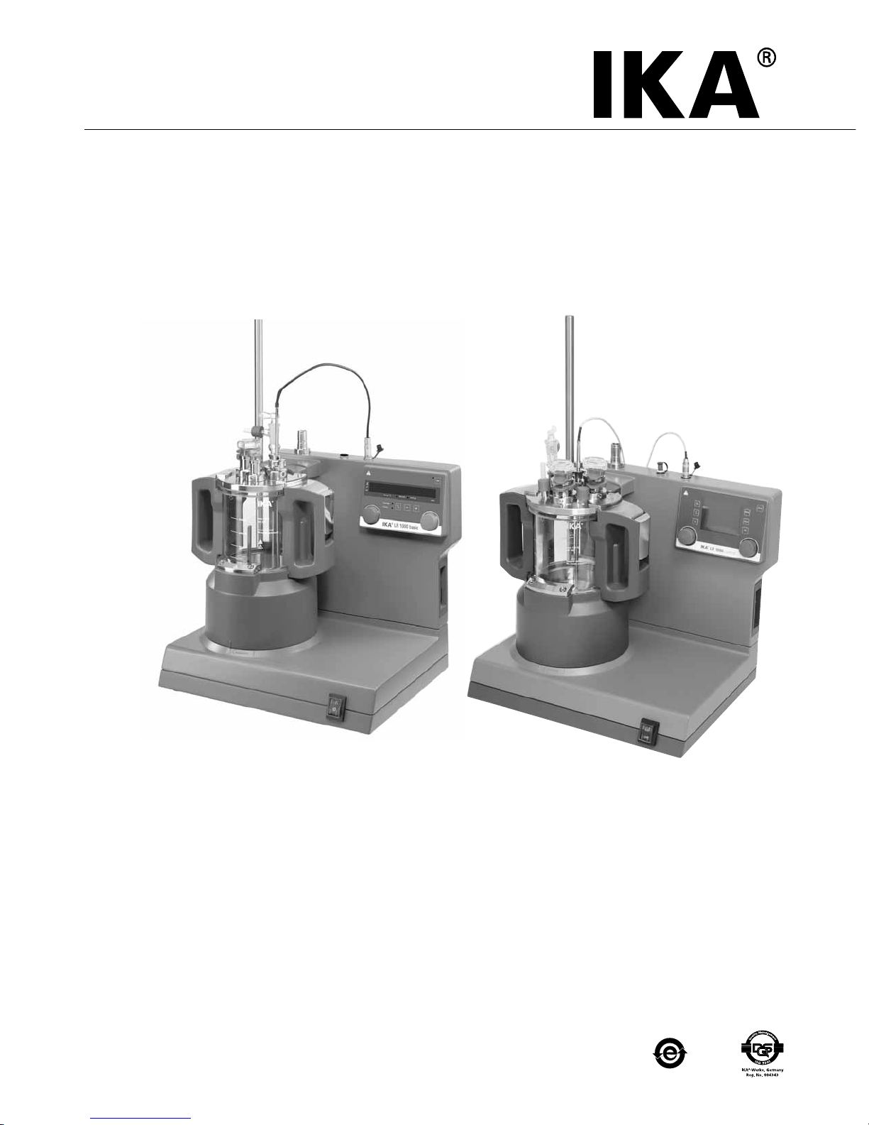
IKA® LR 1000 basic
IKA® LR 1000 control
LR 1000 basic/control_012015
20000005830
Operating instructions EN
Page 2
2
Contents
EN
EC
Declaration of Conformity
Explication of warning symbols
Source language: German
We declare under our sole responsibility that this product corresponds to the regulations 2006/42/EC and 2004/108/EC and
conforms with the standards or standardized documents: EN 61010-1, -2-010, -2-051; EN ISO 12100-1, -2; EN 60204-1
and EN 61326-1.
Page
EC Declaration of Conformity 2
Explication of warning symbols 2
Safety instructions 3
Correct use 4
Unpacking 5
System configuration 5
Setting up 7
Safety temperature limit 8
Operator panel and display 9
Commissioning 11
Interface and output 17
Maintenance and cleaning 20
Error codes 22
Warranty 23
Accessories 23
Materials in contact with medium 23
Technical data
24
DANGER
CAUTION
WARNING
NOTICE
indicates an imminently hazardous situation, which, if not avoided, will result in death, serious
injury.
indicates a potentially hazardous situation, which, if not avoided, can result in death, serious
injury.
indicates a potentially hazardous situation, which, if not avoided, can result in injury.
indicates practices which, if not avoided, can result in equipment damage.
Page 3
3
• Socket must be earthed (protective ground contact).
• The voltage stated on the type plate must correspond to
the mains voltage.
Beware of hazards due to:
- flammable materials
-
combustible media with a low boiling temperature
- glass vessel breakage
- overfilling of media
- unsafe condition of container.
• The device will automatically restart in mode B and C fol-
lowing any interruption to the power supply
• The equipment is not designed for overpressure use.
• The equipment is designed for operation at vacuum set-
tings up to 25 mbar.
• Certain applications and materials may be hazardous. You
should take precautions to prevent contact with, or inhalation of, toxic liquids, gases, fumes, vapours or powders.
• Risks may also be posed by biological or microbiological
substances.
The reactor system must always
be ventilated when working under
normal pressure in order to prevent
any pressure build-up caused by highly volatile gases or
unpredictable reaction pressure gradients. Condense volatile gases using a cooler with a standard ground connec-
tor (e.g. a reux condenser) on the reactor cover.
• Observe the maximum permissible temperatures (see sec-
tion “Technical data“) in the reactor vessel.
Before you fill the reactor vessel,
ensure that the reagents used do
not corrode the seal.
• Ensure that the external temperature sensor is inserted in
the media to a depth of at least 20 mm.
• Only use IKA® approved accessories!
• Use only original IKA® spare parts!
•
When the reactor vessel or the vessel cover is removed
during operation, the stirring and the heating function
will be switched off automatically. Restart the stirring and
heating function by pressing on knob (A) and (B)
after the
reactor vessel or vessel cover is placed and locked again
(see Fig. 11 and Fig. 12).
Safety instructions
General instructions:
•
Read the operating instructions fully before starting
up and follow the safety instructions.
• Keep the operating instructions in a place where they can
be accessed by everyone.
• Ensure that only trained staff work with the equipment.
• Follow the safety instructions, guidelines, occupational
health and safety and accident prevention regulations.
• Uncontrolled reactions can be triggered by mixing the
heated material insuciently or by the energy generated
by selecting a speed that is too high. In case of these and
other increased operational hazards, users must take additional appropriate safety precautions. In any case, when
using critical or hazardous materials in your processes,
IKA® recommends to use additional appropriate mea-
sures to ensure safety in the experiment. For example, users can implement measures that inhibit fire or explosions
or comprehensive monitoring equipment. Furthermore,
users must make sure that the unit switch of the IKA®
product can be accessed immediately, directly and without risk at any time.
If installation or positioning cannot ensure this access at all times,
an additional EMERGENCY STOP
switch that can be easily accessed must be installed in
the work area.
• Only process media that will not react dangerously to the
extra energy produced through processing. This also applies to any extra energy produced in other ways, e.g.
through light irradiation.
• Do not operate the instrument in explosive atmospheres,
with hazardous substances or under water.
• Process pathogenic materials only under a suitable fume
hood. Please contact IKA® application support if you
have any question.
• Set up the device in a spacious area on an even, stable,
clean, non-slip, dry and fireproof surface.
• Protect the instrument and accessories from bumping and
impacting.
•
Check the instrument and accessories beforehand for dam-
age each time when you use them. Do not use damaged
components.
• Safe operation is only guaranteed with the accessories described in the ”Accessories” section.
• Always switch the device switch in the OFF position or
disconnect the power before changing and fitting any accessories.
• The instrument can only be disconnected from the mains
supply by pulling out the mains plug or the connector
plug.
• The socket for the mains cord must be easily accessible.
DANGER
WARNING
NOTICE
WARNING
Page 4
4
Cooling:
• Ensure that the thermostat used for tempering is fully efficient. A defective thermostat can cause uncontrolled
reactions.
Using the adequate hoses for cooling
purposes.
Weighing:
Weighing function integrated into
the LR 1000 control feet. Unpack
and set up cautiously.
Maintenance:
• The feet of the equipment must be clean and undamaged.
• The device must only be opened by trained specialists,
even during repair. The device must be unplugged from
the power supply before opening. Live parts inside the instrument may still be live for some time after unplugging
from the power supply.
Covering or parts that are capable of
being removed from the unit with-
out accessory equipment have to be
reattached to the unit for safe operation in order to prevent, for example, the ingress of fluids, foreign matter, etc..
Stirring and dispersing:
• Moving and rotating equipment parts also constitute a
hazard.
Rotating tools are dangerous! The
anchor stirrer and the dispersing el-
ement must only be operated when
the reactor vessel is fully closed. Do not start up the laboratory reactor when it is open.
• If the dispersing element rotate when they are covered in
a product and the reactor is open, this will cause parts or
liquids to be projected outwards.
• Gradually increase the speed.
• The equipment may heat up by stirring.
Heating:
Risk of burns! Exercise caution when
touching the heating block and the
glass vessel. The cover of the vessel could reach high temperature when you boil liquid for
long time. Pay attention to the residual heat after switching off.
Only process and heat up any me-
dia that has a flash point higher
than the adjusted safe temperature
limit that has been set (see section “Technical data“).
The safe temperature limit must always be set to at least
25 °C lower than the fire point of the media used.
• Use:
The IKA® LR 1000 system is a compact reactor system.
It has been designed to simulate and optimize chemical
reaction processes and can also be used for mixing, dispersion and homogenization in modeling processes.
Operating mode: Tabletop device.
• Range of use (indoor use only):
- Laboratories - Schools
- Pharmacies - Universities
Correct use
This equipment is suitable for use in all areas except:
- Residential areas
-
Areas that are connected directly to a low-voltage supply
network that also supplies residential areas.
The safety of the user cannot be guaranteed:
- if the instrument is operated with accessories that are not
supplied or recommended by the manufacturer
- if the instrument is operated improperly or contrary to the
manufacturer’s specifications
- if the instrument or the printed circuit board are modified
by third parties.
DANGER
CAUTION
NOTICE
NOTICE
DANGER
CAUTION
Page 5
5
• Unpacking:
- Please unpack the device carefully
- In the case of any damage a detailed report must be
sent immediately (post, rail or forwarder).
• Delivery scope:
LR 1000 basic:
- LR 1000 basic base
- Reactor vessel LR 1000.1 (see Fig. 4)
- Temperature sensor
- Receptacle for temperature sensor
- Support rod
- 2 pieces hose connectors
- Mains cable
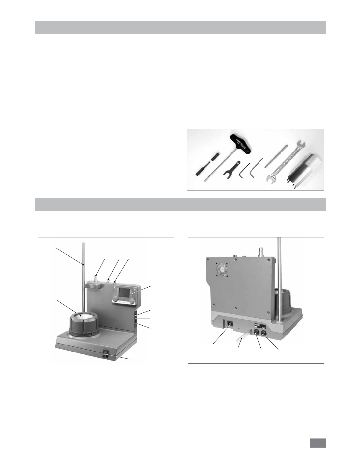
- Tool kit (see Fig. 1)
- Operating Instructions
- Warranty card.
Unpacking
Fig. 1
System configuration
IKA® LR 1000 basic/control laboratory reactor comprises:
• LR 1000 basic/control base:
1: Mains switch
2: Control elements and display
3: Heating block (with integrated cooling coils for
connecting external cooling systems)
4: Support rod, for securing accessories
5: Temperature sensor socket
6*: pH-probe socket (for LR 1000 control only)
7: Reception for disperser (Park station)
Fig. 2
4
1
3
2
57
8
9
10
Fig. 3
11
12
13
14
6*
8: Adjustable safety circuit
9: USB port
10: RS 232 port
11: Power socket
12: Condensate drain*
13: Cooling connection IN*
14: Cooling connection OUT*
*
Note: Cooling connections can be used only for cooling purpose.
LR 1000 control:
- LR 1000 control base
- Reactor vessel LR 1000.3 (see Fig. 5)
- Temperature sensor
- Receptacle for temperature sensor
- Support rod
- 2 pieces hose connectors
- USB cable
- Mains cable
- Tool kit (see Fig. 1)
- Operating Instructions
- Warranty card.
Page 6
6
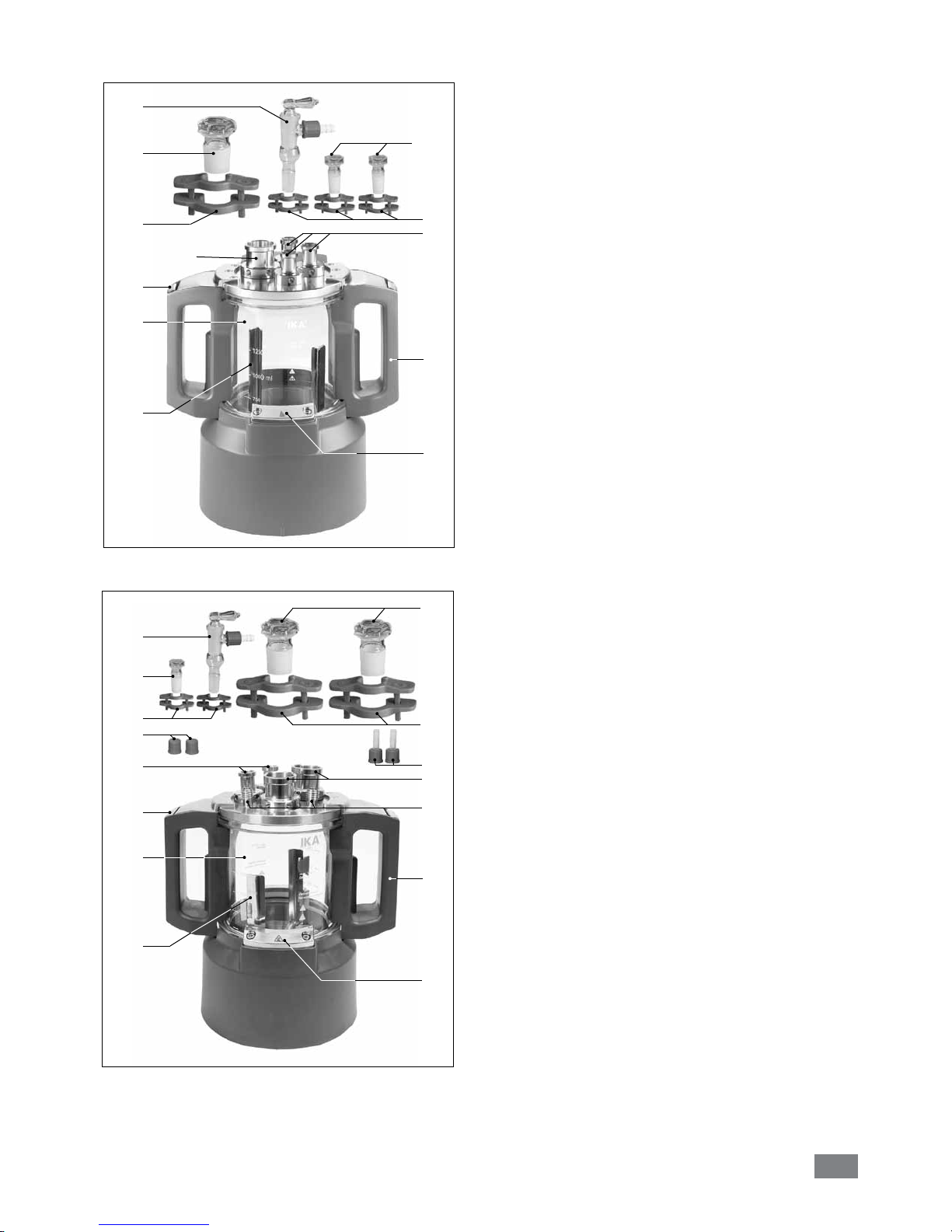
• Reactor vessel (LR 1000.1):
15: Glass vessel (Borosilicate glass 3.3)
16: Handle
17: Cover latch
18: Vessel locker
19: Anchor stirrer
21: NS 29/32 (1x)
22: NS 14/23 (3x)
24: Safety clips NS 29/32 (1x)
25: Stopper NS 29/32 (1x)
26: Safety clips NS 14/23 (3x)
27: Stopper NS 14/23 (2x)
28: Vacuum cock NS 14/23 (1x)
Fig. 4
21
22
24
25
26
27
28
Reactor vessel (LR 1000.3):
20
21
22
15: Glass vessel (Borosilicate glass 3.3)
16: Handle
17: Cover latch
18: Vessel locker
20: Anchor stirrer with scraper (PEEK)
21: NS 29/32 (2x)
22: NS 14/23 (2x)
23: Neck with GL 14 thread (2x)
24: Safety clips NS 29/32 (2x)
25: Stopper NS 29/32 (2x)
26: Safety clips NS 14/23 (2x)
27: Stopper NS 14/23 (1x)
28: Vacuum cock NS 14/23 (1x)
29: Screw cap GL 14 (2x)
30: Hose connector and nut GL 14 (2x)
Fig. 5
24
25
26
27
28
18
16
23
15
17
16
18
17
19
15
29
30
Page 7
7
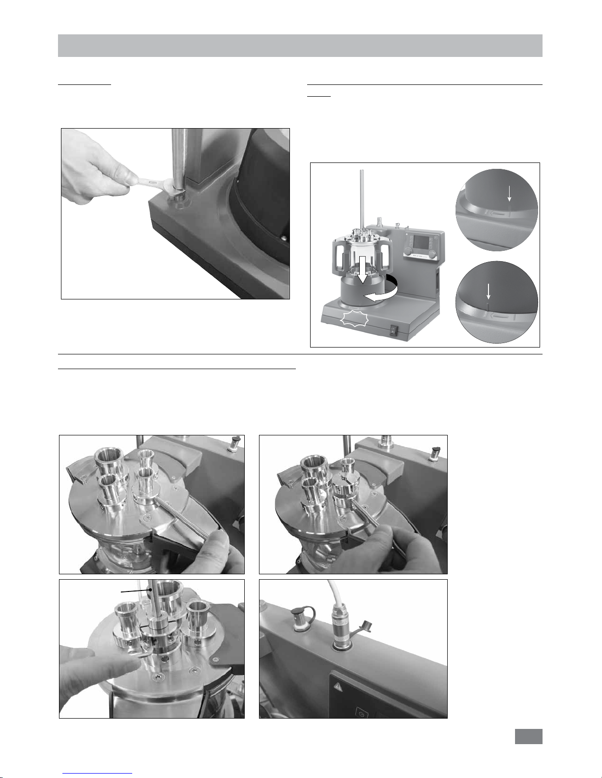
Attach the reactor vessel to the LR 1000 basic/control
base:
Ensure the LR 1000 basic/control is set up on an even,
stable, clean and non-slip working table.
Set the reactor vessel to the LR 1000 basic/control base
carefully and ensure it is properly attached as indicated in
following image.
Setting up
CLICK
Unlock
Lock
Fig. 7
Support rod:
Screw the support rod onto the LR 1000 basic/control
base with the double open end wrench included with the
device until the end stop is reached.
Fig. 6
Installation and connection Pt 100 temperature sensor:
Remove a standard connection NS 14/23 from the reactor cover for connection the temperature probe.
Screw the LR 1000.61 sensor receptacle with sealing in the reactor cover.
Plug in the probe and pay attention to the minimum immersion depth and freewheeling of the anchor mixer. Fix the position
in the housing with the two screws for sliding stop.
Connect the temperature probe with the appropriate socket.
Fig. 8
Pt 100
Page 8

8
Connect external cooler:
The reactor can connect an external cooler (e.g. IKA®
RC 2 basic or RC 2 control)
via the connections (13,
14, see Fig. 3) at the back of the device. The cooling con-
nections IN and OUT is labelled accordingly at the back of
the device. There are two connectors included for connecting cooling hoses. They can be connected to a hose with a
10 mm inner diameter. By positioning and light pressure in
the direction of the connector, the connector is locked/connected to the cooling connections IN/OUT on the housing.
The connectors are unlocked by coaxially positioning the
unlocking lever and pressing slightly.
Fig. 9
Safety temperature limit
Fig. 10
Potentiometer
The maximum attainable heating temperature is restricted
by an adjustable safety circuit. Once the safety temperature
has been attained, the instrument switches off the heating
function.
The safety temperature must always
be set to at least 25 ºC lower than
the flash point of the fluid used.
Factory setting: max. value
Setting the safety temperature limit
After switching on the instrument, the safety temperature
can be adjusted with screwdriver delivered with the device.
The safety temperature setting will appear on the display.
Do not turn the potentiometer beyond the clockwise or anti-clockwise
stop, since this will damage the po-
tentiometer irreparably.
WARNING
NOTICE
Page 9

9
A
B
F
O
L
C
Fig. 11
D
E
G H I
J
K
M
N
P
R
Operator panel and display
•
LR 1000 basic:
Item Designation Function
A Rotating/pressing knob: Start/stop the stirring function
Change the settings of stirring speed
B Rotating/pressing knob: Start/stop the heating function
Change the settings of the temperature
C
Counter/Timer (C/T) button:
Switch between “Counter“ and “Timer“ function
D Timer (+): Increase the “Timer“ value
E Timer (-): Decrease the “Timer“ value
F Key button: Lock/unlock knobs and keys
G Display, temperature: Display the set and actual temperature
H Display, counter/timer: Display the counter and timer values
I Display, stirring speed Display the set and actual stirrer speed
J LED, timer The LED indicates the “Timer“ function is activated
K LED, counter The LED indicates the “Counter“ function is activated
L LED, hh:mm The LED indicates the “Timer“ or “Counter“ is working with unit hh:mm
M LED, mm:ss The LED indicates the “Timer“ or “Counter“ is working with unit mm:ss
N LED, key button Indicates that the function of key and knobs is deactivated
O LED, heating The LED indicates the heating function is activated
P LED, temperature sensor The LED indicates the external temperature sensor is connected
R LED, Set The LED lights simultaneously with the display of the set value for heating function.
Page 10

10
Item Designation Function
A Rotating/pressing knob: Start/stop the stirring function
Change the settings of stirring speed in working screen
Navigation, selecting and changing the settings in the menu
B Rotating/pressing knob: Start/stop the heating function
Change the settings of the temperature in working screen
F Key button: Lock/unlock knobs and keys
S “Menu” button: Press it once: main menu is displayed
Press it a second time: back to the working screen
T “Back” button: Return to the previous menu level
U Timer button: Enable timer display
V Weighing button: Enable weight display
W Display: Display and setting information
X F1 button: not currently assigned
Y F2 button: not currently assigned
A
B
S
T
F
U
V
X
Y
Fig. 12
•
LR 1000 control:
W
Page 11

11
Check whether the voltage specified on the type plate
(LR 1000 basic/control base) matches the mains voltage
available.
The power socket used must be
earthed (protective earth conductor
contact).
Commissioning
Safety temperature
Default working setting
Standby
•
LR 1000 basic
Switch on the instrument:
After switching on the mains switch on the front of the
device, all LED segments light up during the self-test.
Then the software version, operation mode, safety temperature and working settings will be shown. Then the
device enters standby status and is ready for operation.
Software version
Starting
Operating mode
Operation mode
The instrument can be operated in three different modes
(A, B, C).
Operation mode A:
After power on/power failure no automatic restart of functions.
Operation mode B:
After power on/power failure automatic restart of functions, depending on previous settings.
Operation mode C:
Set values (set in A or B) cannot be changed.
After power on/power failure automatic restart of functions,
depending on previous settings.
Factory setting: mode A
Turn the rotating/pressing knob (A), the speed value can
be adjusted. Press right rotating/pressing knob (A, see
Fig. 11) to activate the stirring function.
Turn the rotating/pressing knob (B), the temperature value can be adjusted. Press left rotating/pressing knob (B,
see Fig. 11) to activate the heating function.
Changing the mode
Switch off the instrument with the mains switch
Press and hold rotating/pressing knob (B)
Switch on the instrument with the mains switch
Release rotating/pressing knob (B)
The operation mode will be change to next operation
mode in the sequence A – B – C – A – B – C – A etc.
Heating function:
The heating function can be started or stopped by pressing
the left rotating/pressing knob (B). Then, the target temperature value and the actual temperature value will ap-
pear on display (G, see Fig. 11) alternately. When the set
temperature value is display, LED (R, see Fig. 11) lights up.
The heating temperature value can be adjusted by turning
the left rotating/pressing knob (B).
The value could be changed in standby or operation process.
Temperature sensor calibration:
Press and hold the Knob B for more than 5 seconds to
enter calibration mode.
“CAL“ will be shown on display (H)
Turn Knob B to adjust the value on display (G) to the
calibration value.
Press Knob A to confirm the value and finish the calibration.
Note: Pressing and holding the knob A for more than 5
second will reset the calibration to factory setting.
If these conditions are met, the device is ready for operating
after plugging in the mains plug.
If these procedures are not followed, safe operation cannot
be guaranteed and/or the equipment may be damaged.
Observe the ambient conditions (temperature, humidity,
etc.) listed under “Technical Data”.
Fig. 13
Page 12

12
Counter and timer function:
Counter function:
When the heating function is started, the counter will start
automatically. The counter is displayed with 4 digits.
When the operating time is less than 1 hour, the counter
work with minute/second (mm:ss) mode and LED (M, see
Fig. 11) lights.
If the operating time exceeds 1 hour, the display switches
from minute/second mode to hour/minute (hh:mm) mode.
LED (L, see Fig. 11) lights indicate the status.
If the operating time exceeds 100 hours, the display switches from hour/minute mode to hour mode .
In hour mode, only whole hours are displayed.
In day mode, only whole days are displayed.
Hour mode
Day mode
Stirring function:
The stirring function can be started or stopped by pressing
the right rotating/pressing knob (A). The speed can be adjusted during operation.
The displayed value will flash until reaching the target speed.
Timer function:
The Time (+) button (D
, see Fig. 11
) or Time (-) button (D
,
see Fig. 11
) is used to adjust the heating time. If the timer
value is more than 1 hour, the display switch to hour/minute
(hh:mm) mode from minute/second (mm:ss) mode. The
LED (L) lights.
The max. value for timer is 99:59 (hh:mm).
Switching between “Counter” and “Timer” function:
The “Counter” function could be switch to “Timer“ function by pressing the Counter/Timer key (C
, see Fig. 11
).
The timer LED (J
, see Fig. 11
) indicates the “Timer“ func-
tion is activated.
Press the Counter/Timer key (C) again, the “Counter“ func-
tion will be activated and counter LED (K, see Fig. 11) lights.
•
LR 1000 control:
Switch on the device:
After switching on the device using the power switch on
the front panel the device name and the software version
are displayed on the screen.
After a few seconds, the working screen is shown on the
screen,
device
is ready for operation.
Lab Reactor
LR 1000 Control
Version X.X.XXX/X.XX
Fig. 14
A
25.0
actual °C
0 10
set °C set rpm
Safe Temp.: 210 °C
0
actual rpm
Fig. 15
Turn the rotating/pressing knob (A), the target speed setting can be adjusted on the working screen. Press rotating/
pressing knob (A, see Fig. 12), the stirrer start to running.
Turn the rotating/pressing knob (B), the temperature setpoint can be adjusted. Press rotating/pressing knob (B, see
Fig. 12) to activate the heating function.
Explanation of symbols on the working screen:
The symbols displayed change depending on the status and
settings of the instrument. The screen below shows the
most significant symbols on the working screen.
PC
A
Safe Temp.: 200 °C Timer: 00:00:00
pH-Value: 0.0 Δ Torque:
0%
100.0
actual °C
100
actual rpm
100.0
set °C
100
set rpm
Fig. 12
Fig. 16
Page 13

13
Key:
This symbol means that the function of the keys and the
rotary knobs for controlling the device are disabled.
The symbol no longer appears if the functions are enabled
once again by pressing the key button a second time.
Temperature Sensor:
This symbol appears when the external temperature sensor
is connected.
A Operating Mode:
This symbol indicates the operating mode currently selected (A,
B, C).
USB:
This symbol means the device is communicating via a USB cable.
Heating:
This symbol indicated the heating function is activated.
indicated active heating process.
Motor activated:
This symbol indicates the rotation status of the stirrer.
PC PC control:
This symbol indicates the device is control via a PC.
Menu navigation and structure:
Menu navigation:
Press the “Menu” key (S).
Select the menu by
turning the rotating/pressing knob (A) to the right or
left to select the desired menu or sub-menu, which can then be selected by
pressing the rotating/pressing knob (A).
Push or Turn the rotating/pressing knob (A) again to select the desired
menu option and edit the values or settings, or activate/deactivate a function.
Turn the rotating/pressing knob (
A
) on “OK“ or Press the "Back" key (T) or
"Menu" button (S) to end the procedure and return to previous menu or
working screen.
Note: The display shows the activated menu option highlighted in yellow color.
Stirring
Torque trend measurement
Intermittent mode
Speed limit
> Stirring
Torque trend measurement
The torque trend measurement
calculates the relative torque
changing inside the medium.
Note: If you press the “Menu“ key (S), the system skips directly back to the working screen.
If you press the “Back“ key (T), the system skips back to the previous display.
Menu navigation: Press the “Menu “ key (S) and rotate rotating/pressing knob (A)
Press the ”Back” key (T) or the ”Menu” key (S)
Stirring
Menu
A
25.0
actual °C
0 10
set °C set rpm
Safe Temp. 210 °C
0
actual rpm
Menu
Menu
Back
BackBack
Fig. 18
Navigation controls
in the menu
A
S
T
Fig. 17
Page 14

14
Menu structure:
Stirring
Torque trend measurement ……………………………………………………… -
Intermittent mode
Run/Stop
…………………………………........ -
Interval Run Time
…..…………...
01:00 [mm:ss]
Stop Time
……………….
00:10 [mm:ss]
Speed limit ………………………………………………………………………...
150 rpm
Heating
Control method
Accurate …………………………………………
activated
Fast ……………………………………………… -
Limits
Medium limit …………………………………… 120
Limit information Medium limit …………… 120
Heating block …………… 180
Temperature sensor
Calibration 2-point calibration ……… -
3-point calibration ……… -
Reset calibration values ………………………… -
Timer
Set
…………………………………………………………………………………..
00:00:00 [hh:mm:ss]
Display
……………………………………………………………………………..
-
Operating Mode
A
………………………………………………………………….........…………..
activated
B
…………………………………………………………………….........………..
-
C
…………………………………………………………………….........………..
-
Display
Torque trend measurement
……………………………………………………...
-
pH value
……………………………………………………………………...……
-
Timer
…………………………………………………………………..…………..
activated
Safety
Time out
Set ……………………………………………… 00:30 [mm:ss]
Speed …………………………………………… 10 rpm
Temperature …………………………………… 30 ºC
Password
…………………………..…………………………………................
000
Safe Temp. confirmation
…….…………………………………………………
-
Factory settings
Menu
Weighing
pH Probe
Measurement
…………………………………………………………………….. -
Calibration 2-point calibration ……………………………… -
3-point calibration ……………………………… -
Reset calibration values …………………………………………………………… -
Calibration 2-point calibration ……………………………… -
3-point calibration ……………………………… -
Reset pH probe ……………………………………………………………………. -
Display ……………………………………………………………………………… -
Settings
Languages
Display
Sound
Factory settings
Bluetooth
Information
Version
…………………………………………
yes
Operating mode
………………………………
yes
Interval run
………………………….…………
yes
Interval stop
………………………...…………
yes
Medium limit
…………………………………
yes
Heating block Limit
……………………………
yes
Time out
………………………………………
yes
Time out temperature
………………………
yes
Time out speed
……………………………
yes
English
………………………………………….
activated
Deutsch
…………………………………………
-
···
………………………………..……………………………………..…
-
Background Black
………...………....
activated
White
…………………..
-
Key tone
………………………………………..
-
Page 15

15
Menu (Details):
Stirring:
Torque trend measurement:
The torque trend measurement is used to deduce the
change in viscosity of the reaction medium. The device is
not designed to measure absolute viscosity. It only measure
and display the relative change in the viscosity of the medium from a starting point specified by the user.
The value can always be reset to 0% by pressing the “Back”
(T, see Fig. 12) membrane key.
Note: Torque trend measurement only works for a constant set speed for the duration of the measurement.
As a result, intermittent mode cannot be used in conjunction
with torque trend measurement.
The current control variable is saved as the reference 0%,
ΔP and shown on the digital display. The change in the viscosity is then shown in %. Depending on whether the viscosity increases or decreases, the percentage rises or falls
above or below 0% respectively.
Intermittent mode:
The menu allows the user to activate the “Run/Stop“ function. The run time and stop time can be set separately.
Speed limit:
The menu allows the user to set the desired maximum upper speed limit for the reactor system. The initial setting is
the maximum permissible speed of the stirrer. If the user
changes this setting, control system of the reactor saves the
new value for future stirring tasks.
If the “Speed Limit” has been changed, then the speed can
be adjusted only within the new range.
Heating:
Control mode:
In the menu, the user is allowed to select “Accurate” or
“Fast” control mode by rotating and pressing knob (A). The
selected control mode is indicated by a tick.
Fast: reach target temperature quickly but with big overshoot and large hysteresis
at the beginning.
Accurate: Reach the target temperature takes somewhat
longer, but for this reason,
the initial overshoot and
the hysteresis are significantly smaller.
Limits:
In “External (ext)“ option, the user is allowed to set the maximum and minimum temperature for external temperature
control. Confirm and store the setting by pressing on “OK“.
Temperature sensor:
In “Calibration“ option, the user is allowed to calibrate the
external temperature sensor.
Weighing:
Measurement:
With the weighing function, the user can perform simple
weighing tasks.
Note: The heating and stirring functions must be deactivated.
Calibration:
• Open the “Calibration” submenu and confirm by press-
ing the rotary knob (A, see Fig. 12)
• Enter the calibration weight and conrm by pressing the
rotary knob (A, see Fig. 12).
• Place the calibration weight on the device and wait until
the device indicates that the calibration process has been
completed.
Depending on the selected calibration mode, 2-point or
3-point must follow these steps two or three times.
Once the calibration process has been completed successfully, the weighing module is ready for use.
Regularly re-calibrate the device.
Timer:
In the menu the user can specify that the timer is displayed
on the working screen. A tick shows that the option is activated. This setting allows the user to specify the actual time
for the heating procedure.
A default time can also be set for the timer. This setting allows the user to start the heating task for a standard time.
The device stops automatically after expiry of the set time,
and the set time used for the heating procedure appears in
the display.
Note:
The user can stop the stirring function before expiry
of the set time. In this case the countdown of the timer is
interrupted.
pH Probe:
Calibration:
The pH Probe must be calibrated before being used to attempt a pH measurement.
The calibration is used to adjust the pH probe and the device so that they work together correctly. As part of the
process, the neutral and pH gradient are specified for the
measurement chain. To complete the calibration, use buffer
solutions in accordance with DIN 19266.
T
Set
t
Page 16

16
Note: a pH calibration can only be carried out with an inserted temperature sensor.
Reset pH probe:
Reset the pH measuring reference.
Display:
Display the measured pH value on working screen.
Operating Mode:
Mode A:
After power on/power failure no automatic restart of functions.
Mode B:
After power on/power failure automatic restart of functions, depending on previous settings.
Mode C:
Set values (set in A or B) cannot be changed.
After power on/power failure automatic restart of functions,
depending on previous settings.
Display:
Here the user can specify which information (torque trend,
pH value, or timer value) is to be displayed on the working
screen.
Safety:
Time Out:
Here you can set a time out. This time out goes into effect
if the communication between the device and the PC has
failed. In this case, the device continues to run with the
set speed and temperature.
Password:
In the menu, the user can protect the device settings using
a password. The user is requested to input the password in
order to access the working screen (factory setting: 000).
Safe temperature confirmation:
Here you must confirm the safety temperature value of the
heating block.
Settings:
Languages:
Here allows the user to select the desired language by turn-
ing and pressing the rotary/push knob (A). A tick indicates
the language that is set for the system.
Display:
Here allows the user to change the background color of the
working screen.
Sound:
Here allows the user to activate/deactivate the key-press
sound and to set the volume.
Factory settings:
Here the user can reset the device to factory settings. The
system requests confirmation to recreate the factory settings.
Pressing the ”OK” button resets all the system settings to the
original standard values set at dispatch from the factory.
Information:
The ”Information” option offers the user an overview of
the most important system settings of the device.
Page 17

17
Abbreviations used:
X,y = numbering parameter (integer number)
m = variable value, integer
n = value of variable, floating point number
X = 1 Pt100 thermometer (external temperature sensor)
X = 2 temperature (heating block)
X = 3 safety temperature
X = 4 stirring speed
X = 6 safety stirring speed
The device can be operated in “Remote” mode via the RS 232
interface or the USB interface connected to a PC and with the
laboratory software Labworldsoft®.
Note: Please comply with the system requirements together with the operating instructions and help section included
with the software.
USB interface
The Universal Serial Bus (USB) is a serial bus for connecting
the device to the PC. Equipped with USB devices can be con-
nected to a PC during operation (hot plugging). Connected
devices and their properties are automatically recognized.
Use the USB interface in conjunction with
Labworldsoft® for
operation in “Remote” mode and also to update the firmware.
USB device drivers
First, download the latest driver for IKA
®
devices with
USB interface from http://www.ika.com/ika/lws/down-
load/usb-driver.zip and install the driver by running the
setup file. Then connect the IKA® device through the USB
data cable to the PC.
The data communication is via a virtual COM port. Configuration, command syntax and commands of the virtual
COM ports are as described in RS 232 interface.
RS 232 interface
Configuration
- The functions of the interface connections between the
machine and the automation system are chosen from the
signals specified in EIA standard RS 232 in accordance
with DIN 66 020 Part 1.
- For the electrical characteristics of the interface and the
allocation of signal status, standard RS 232 applies in accordance with DIN 66 259 Part 1.
- Transmission procedure: asynchronous character transmis-
sion in start-stop mode.
- Type of transmission: full duplex.
- Character format: character representation in accordance
Interfaces and output
with data format in DIN 66 022 for start-stop mode. 1
start bit; 7 character bits; 1 parity bit (even); 1 stop bit.
- Transmission speed: 9600 bit/s.
- Data flow control: none
- Access procedure: data transfer from the stirrer machine to
the computer takes place only at the computer’s request.
Command syntax and format
The following applies to the command set:
- Commands are generally sent from the computer (Master)
to the stirrer machine (Slave).
- The stirrer machine sends only at the computer’s request.
Even fault indications cannot be sent spontaneously from
the stirrer machine to the computer (automation system).
- Commands are transmitted in capital letters.
- Commands and parameters including successive param-
eters are separated by at least one space (Code: hex 0x20).
- Each individual command (incl. parameters and data) and
each response are terminated with Blank CR LF (Code: hex
0x20 hex 0x0d hex 0x20 hex 0x0A) and have a maximum
length of 80 characters.
- The decimal separator in a number is a dot (Code: hex 0x2E).
The above details correspond as far as possible to the recommendations of the NAMUR working party (NAMUR recommendations for the design of electrical plug connections
for analogue and digital signal transmission on individual
items of laboratory control equipment, rev. 1.1).
The NAMUR commands and the additional specific IKA® commands serve only as low level commands for communication
between the machine and the PC. With a suitable terminal or
communications programme these commands can be transmitted directly to the equipment. The IKA® software package, labworldsoft®, provides a convenient tool for controlling
device and collecting data under MS Windows, and includes
graphical entry features, for motor speed ramps for example.
The following table summarises the (NAMUR) commands
understood by the IKA® control equipment.
Page 18

18
Commands:
NAMUR Commands Function
IN_NAME
Input description name
IN_PV_X
X=1;2;3;4;
Reading the real value
IN_SOFTWARE
Input software ID number date, version
IN_SP_X
X=1;2;3;4;6;
Reading the set rated value
IN_TYPE
Input laboratory unit ID
OUT_NAME
Output description name. (Max. 10 characters, default: LR 1000)
OUT_SP_12@n
Setting the WD safety temperature with the echo of the set value
OUT_SP_42@n Setting the WD safety speed with the echo of the set value
OUT_SP_X n
X=1;2;4;6
Setting the rated value to n
OUT_WD1@m Watchdog mode 1: When a WD1 event occurs, the heating and Stirring functions are shut
down and message PC 1 is displayed. Set the watchdog time to m (20...1500) seconds, with
echo of the watchdog time. This instruction starts the watchdog function and must be sent
within the set watchdog time.
OUT_WD2@m Watchdog mode 2: When a WD2 event occurs, the speed setpoint will be set to the WD safety
setpoint speed and the temperature setpoint will be set to the WD safety setpoint temperature.
The PC 2 warning is displayed. The WD2 event can be reset with OUT_WD2@0-resetting also
blocks the watchdog function. Set the watchdog time to m (20...1500) seconds, with echo of
the watchdog time. This command starts the watchdog function and must be sent within the
set watchdog time.
RESET Switching off the instrument function.
START_X
X=1;2;4
Starting the instrument’s (remote) function
STATUS Display of status
1S: mode of operation A
2S: mode of operation B
3S: mode of operation C
S0: manual operation without fault
S1: Automatic operation Start (without fault)
S2: Automatic operation Start (without fault)
<0: error code: (-1)
- 1: error 1
- ... (see table)
-31: error 31
-83:wrong parity
-84: unknown instruction
-85:wrong instruction sequence
-86: invalid rated value
-87: not sucient storage space
STOP_X
X=1;2;4
Switching off the instrument - (remote) function
Variables set with OUT_SP_X are maintained.
“Watchdog” function, monitoring the serial data flow
The following applies to situations where the watchdog function is enabled (see Namur instructions). If no new transmissions of these commands from the PC take place within the preset watchdog time, the heating and shaking functions will
be shutdown according to the watchdog mode selected or will be controlled using the preset setpoints. An operating
system crash, a PC power failure or a fault in the connecting cable to the instrument can cause an interruption in data
transmission.
“Watchdog”– Mode 1
If an interruption in data transmission occurs which is longer than the preset watchdog time, the heating and shaking functions will be shut down and the error message PC 1 will be displayed.
Page 19

19
“Watchdog”– Mode 2
If an interruption in data transmission occurs which is longer than the preset watchdog time, the speed setpoint value will
be set to the WD safety speed setpoint and the temperature setpoint will be set to the WD safety temperature setpoint.
The PC 2 warning message will be displayed.
PC 1.1 Cable:
Required for connecting the RS 232 port to a PC.
1
2 RxD
3 TxD
4
5 GND
6
7 RTS
8 CTS
9
1
RxD 2
TxD 3
4
GND 5
6
RTS 7
CTS 8
9
PC
1
2
3
4
5
6
7
8
9
9
8
7
6
5
4
3
2
1
Fig. 19
USB cable A - Micro B 2.0:
This cable is required to connect USB port (9, see Fig. 2) to a PC.
USB micro B
USB A
A
Fig. 20
Page 20

20
Maintenance and cleaning
Cleaning:
For cleaning disconnect the main plug!
Disassemble the reactor vessel:
Remove the reactor vessel from the LR basic/control base.
Remove the reactor cover from the reactor vessel.
Remove the glass tube from the base as described below.
Use a screwdriver to loosen and remove the four screws on
the two clamps.
Then, both handles can be removed from the glass vessel.
Note: the screws can only be loosened and cannot be removed from the handles.
Now both clamps can be removed. Then remove the glass
tube with handles from the base.
Remove both handles from the glass vessel as following.
Reserve the glass tube with handles. Loosen both screws
with screw driver at the bottom of handles (see Fig. 22).
Disassemble the anchor stirrer:
After removing the glass tube from the vessel base, the anchor stirrer together with the reactor vessel bottom of the
socket can be taken apart from the vessel base (see Fig. 23).
Please pay attention to the O-ring when you disassemble
the reactor vessel.
Open the screw as described in Fig. 24 with the socket
wrench.
O-ring
Fig. 23
Fig. 22
Fig. 24
Fig. 21
Page 21

21
- Wear protective gloves during cleaning the instrument.
- Electrical devices may not be placed in the cleaning agent
for the purpose of cleaning.
- Do not allow moisture to get into the equipment when
cleaning.
- Please consult IKA® before using any cleaning or decon-
tamination methods, other than those recommended here.
- The handles cannot be place in the cleaning agent for
cleaning.
- The only cleaners or disinfectants that may be used are
those that:
- lie in the pH range 5 - 8,
- contain no corrosive alkalis, peroxides, chlorine compounds,
acids or brine.
- All product contacting components are suited for cleaning
in the laboratory dish washers.
Only clean IKA® appliances using these IKA® approved
cleaning agents.
Dirt Cleaning agent
Dyes Isopropanol
Building materials
Water containing detergent, Isopropanol
Cosmetics
Water containing detergent, Isopropanol
Food
Water containing detergent
Fuels
Water containing detergent
Other materials
Please consult IKA
®
Spare parts order:
When ordering spare parts, please give:
- machine type
- serial number, see type plate
- item number and designation of the spare part see
www.ika.com, spare parts diagram and spare parts list.
Repair:
Please send equipment for repair only after it has
been cleaned and is free from any materials which
may constitute a health hazard.
For repairing, please request the “Decontamination Certificate” from IKA®, or download the printout of it from
the IKA® website www.ika.com.
If you require servicing, return the equipment in its original
packaging. Storage packaging is not sucient. Please also
use suitable transport packaging.
Fig. 25
Now you can remove the anchor stirrer as shown in Fig. 25.
All O-rings can now be carefully removed by hand or using a
blunt tool for cleaning too.
Page 22

22
Error codes
The fault is shown by an error message in the display as following if the error occurs.
Proceed as follows in such cases:
Switch off the device using the main switch
Carry out corrective measures
Restart the instrument
Error code Description Effect Corrective action
Error 3
(Er 3)
Internal temperature of device is too high.
Heating off
Motor off
- Switch off the instrument and allow it to cool down.
Error 4
(Er 4)
Motor is blocked or overloaded. Motor off - Switch off the instrument
- Decrease the load and restart again
Error 10
(Er 10)
Remote control is interrupted. Heating off
Motor off
- Change watchdog time
- Check relating connection
Error 11
(Er 11)
External temperature sensor plugged
during heating control.
Heating off - Unplug the external temperature sensor.
Error 12
(Er 12)
External temperature sensor unplugged
during heating control.
Heating off
- Plug in the external temperature sensor
Error 14
(Er 14)
Short circuit of external temperature
sensor or cable.
Heating off
- Check the external temperature sensor and cable
Error 18
(Er 18)
The temperature of safety sensor is
higher than safety temperature setting.
Heating off
- Increase the safety temperature setting or allow
cooling down
Error 51
(Er 51)
Mains voltage is too high. Heating off
Motor off
- Switch off the device and check the mains voltage.
Error 52
(Er 52)
Mains voltage is too low. Heating off
Motor off
- Switch off the device and check the mains voltage.
Er 60
Power is interrupted when heating or
motor control is activated in Mode B and C
–
- Exit error state when any button is pressed.
Only for LR 1000 basic!
If the actions described fails to resolve the fault or another error code is displayed then take one of the following steps:
- Contact the service department
- Send the instrument for repair, including a short description of the fault.
Page 23

23
Accessories
T 25 digital Disperser
S 25 KV - 25 F Dispersing element
S 25 KV - 25 G Dispersing element
S 25 KV - 18 G Dispersing element
LR 1000.41 Shaft receptacle
LR 1000.61 Sensor receptacle
LR 1000.65 pH electrode receptacle
LR 1000.64 pH Electrode
Warranty
In accordance with IKA® warranty conditions, the warranty
period is 24 months. For claims under the warranty please
contact your local dealer. You may also send the machine
direct to our factory, enclosing the delivery invoice and giving
reasons for the claim. You will be liable for freight costs.
LR 1000.20 Flow breaker/bae
RC 2 basic Thermostat
RC 2 control Thermostat
HPVC 8 PVC hose
MVP10 basic Vacuum pump
VCV1 Vacuum control valve
VSS1 Vacuum safety set
labworldsoft
®
The warranty does not cover worn out parts, nor does it
apply to faults resulting from improper use, insucient care
or maintenance not carried out in accordance with the instructions in this operating manual.
Only for LR 1000 control!
See more accessories on www.ika.com.
Materials in contact with medium
Reactor cover AISI 316 L / AISI 316 TI / PTFE / Borosilicate glass 3.3
Bottom AISI 316 L / AISI 316 TI
Reactor vessel Borosilicate glass 3.3
Anchor stirrer AISI 316 L / AISI 316 TI
Temperature sensor AISI 316 L / AISI 316 TI
Shaft seal PTFE
LR 1000.1
O-ring FKM
LR 1000.3
O-ring FFKM
Scraper PEEK
Page 24

24
Technical data
LR 1000 basic LR 1000 control
Nominal voltage VAC 100 – 120
230
Frequency Hz 50 / 60
Input power W 1200
Viscosity max. mPas 100000
Usable volume ml 300 – 1000
Useful volume with dispersing ml 500 – 1000
Attainable vacuum mbar 25
Stirring speed range rpm 10 – 150
Speed display LED TFT
Speed setting resolution rpm 1
Speed deviation rpm ± 5
Working temperature max. (medium) °C 120
Temperature display LED TFT
Temperature setting resolution K 1 0.1
Temperature measurement resolution K 0.1
Heating control accuracy K ± 1
Connection for external temperature sensor Pt 100
Control accuracy with external sensor K ± 0.2
Adjustable safety circuit °C 47 (± 10) – 225 (± 20)
Type of cooling Liquid through cooling
Minimum temperature of the cooling medium °C 3
Cooling medium permissible pressure bar 1
Weighing range kg - 0 – 2
Weighing resolution g - 1
pH meter interface no yes
pH value display - TFT
pH display range - 0 – 14
pH display resolution - 0.1
Nominal torque Ncm 3
Torque trend display - TFT
Timer function yes
Timer display LED TFT
Interface USB, RS 232
Protection class acc. to EN 60529 IP 21
Permissible ambient temperature °C +5 ... +40
Permissible ambient humidity (relative) % 80
Dimension (W x D x H) mm 443 x 295 x 360
Weight kg 16
Operation at a terrestrial altitude m max. 2000
Subject to technical changes!
Page 25

IKA
®
- Werke GmbH & Co.KG
Janke & Kunkel-Str. 10
D-79219 Staufen
Tel. +49 7633 831-0
Fax +49 7633 831-98
sales@ika.de
www.ika.com
 Loading...