

Page 1
KS4000_1
KS 4000 i control
KS 4000 ic control
Page 2
Safety instructions
EN
Contents
Page
Warranty 2
Safety instructions 17
Correct use 19
Unpacking 19
Commissioning 19
Switch on 19
Setting the safety limit values 20
Opreator panel and display 20
Function Shaking 21
Timer 21
Function Heating 21
Operating modes 22
Setting the operating mode 22
External temperature sensor 22
Kalibration - temperature 22
Reset 23
Appliance variant KS 4000 ic control 23
Attachments 24
Error codes 24
Interface and outputs 27
Maintenance and cleaning 28
Accessories 30
Technical data 30
• Read the operating instructions in full before starting up
and follow the safety instructions.
Kep the operating instructions in a place where they can be
accessed by everyone.
The media used in the appliance may result in danger specific to the media and the process. This applies, for example, to shaking cultures with living cells and to aggressive
or flammable media.
germents can become, if they arise with one another in
combination, a larger endangerment.
describe the dangers and resulting safety measures in
more detail.
This appliance should only be operated by suitably trained personnel familiar with the appliance and authorized to work in this
area.
• The machine may only be opened by trained specialists - even
during repairs. The machine is to be unplugged from the mains
before opening. Live parts inside the machine may still be live
for some time after unplugging from the mains.
• NOTE ! Covering or parts that are capable of being removed
from the unit without accessory equipment have to be reattached to the unit for safe operation in order to prevent, for
example, the ingress of fluids, foreign matter, etc. .
• Wear your personal protective equipment in accordance with
the hazard category of the medium to be processed.
Otherwise there is a risk of:
- splashing liquids
- projectile parts
- body parts, hair, clothing and jewellery getting caught.
• Follow the safety instructions, guidelines, occupational health
and safety and accident prevention regulations.
• Beware of the high dead weight of the appliance when transporting. Ensure that your fingers do not get crushed when setting down the appliance.
• Always install the appliance on a flat, stable non-slip base.
• Pay attention to the vessels on the shaking table when setting
the shaking rate. This will prevent any of the medium to be
shaken from spurting out of the sample vessels.
Particulars as small estimated endan-
This manual cannot
17
Page 3
• Ensure that parts of the body, hair or items of clothing cannot
be trapped by the motion parts.
• Never touch moving parts.
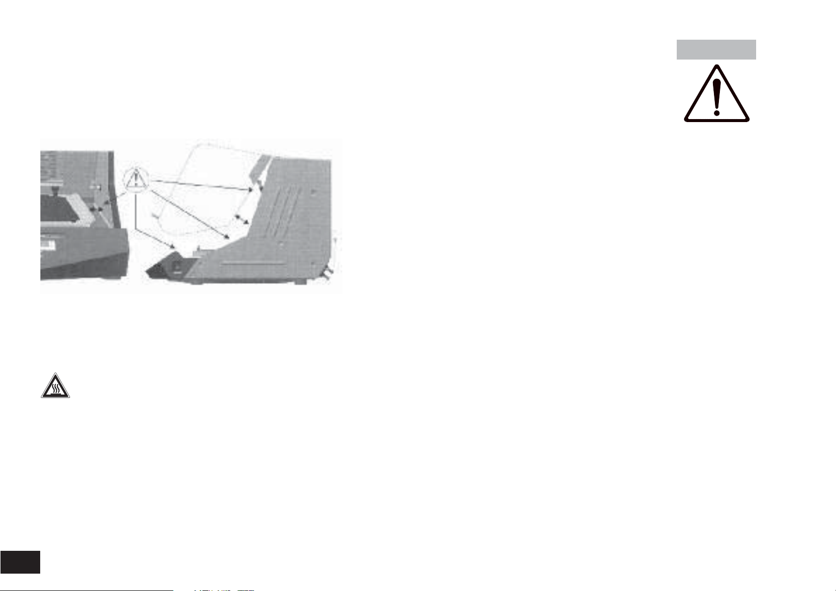
Caution! The shaker still runs after the cover has been
opened. Wait for it to stop running.
(Risk of being crushed, shocked or cut, see figure illustrating
danger points).
• Should vessels break during operation or the media be spilt, interrupt the shaking process immediately, remove any vessel residue
and clean the appliance.
Danger of being burnt! Exercise caution when touching
housing components and attachments. They may become
hot. Watch for residual heat after appliance has been switched off.
• Pay attention to the risk of
- flammable materials - glass breakage
- flammable media with low boiling temperatures
- level of medium which is too high
- biological and microbiological materials
• All accessories and vessels in place for the shaking process
must be firmly secured.
• Shaking vessels which are not properly secured could get
damaged or be projected out, thus causing injury. It is essenti-
• If you notice that the device is not running smoothly, the
• Because of improper loading and the position of the center of
• Additional hazards to the user may occur if inflammable mate-
• Furthermore, the shaking unit may only be used to stir those
•
• When using an external temperature sensor, it must always be
• The safety of the user cannot be guaranteed if the appliance is
• Caution! Never process and heat up any media that has a
The safe temperature limit must always be set to at least 25 °C
lower than the fire point of the media used.
• When servicing, the wiring selected by IKA must be set up
• Avoid allowing objects to push or strike the agitation table.
• Keep a minimum distance of 100mm from the appliance on all
al to regularly check that the vessels to be shaken and the
attachments are firmly secured, especially before using the
appliance again.
speed must always be reduced until no more uneveness
occurs in the operation.
gravity, dynamic forces may arise during the agitation process
that cause the shaker to move about on the table.
For restrictions of load capacity and material weight during
high shaking frequencies, please see the description in the
"Attachments" section.
rials are used during the shaking operation.
materials or material mixtures that the user knows will not
react dangerously to the extra energy produced by the stirring.
This also applies to extra energy by means of solar radiation
during the shaking procedure.
The shaker may not been used in explosive atmospheres, for
mixing dangerous substances or under water.
in the medium. Immerse the external temperature sensor at
least 20mm into the medium.
operated with accessories that are not supplied or recommended by the manufacturer or if the appliance is operated improperly, contrary to the manufacturer’s specifications.
flash point higher than the adjusted safe temperature limit that
has been set.
again!
sides.
18
Page 4

Correct use
Commissioning
• Use
- For mixing and/or heating liquids
• Range of use
- Laboratories - Schools
- Pharmacies
This device is suitable for use in all areas except:
- Residential areas
- Areas that are connected directly to a low-voltage supply network that also supplies residential areas.
The safety of the user cannot be guaranteed if the appliance is
operated with accessories that are not supplied or recommended by the manufacturer or if the appliance is operated improperly contrary to the manufacturer’s specifications or if the appliance or the printed circuit board are modified by third parties.
Unpacking
•
Unpacking
- Please unpack the device carefully
- In the case of any damage a detailed report must be set immediately (post, rail or forwarder)
Contents of package
•
KS 4000 i control KS 4000 ic control
- Shaking device
-
Mains cable - Mains cable
- Operating instructions - Operating instructions
- 4 clamping screws short - 4 clamping screws short
- 2 clamping screws long - 2 clamping screws long
-
Temperature sensor PT 1000.60- Temperature sensor PT 1000.60
- Shaking device (temperierbar)
- 2 hose connecting pieces
- unlocking handle
Make sure before start-up of the equipment that the drain hose
leads into a drain!
Check whether the voltage specified on the type plate matches
the mains voltage available. The power socket used must be earthed (protective earth conductor contact). If these conditions are
met, the device is ready to operate after plugging in the mains
plug. If these procedures are not followed, safe operation cannot
be guaranteed and/or the equipment may be damaged.
Observe the ambient conditions (temperature, humidity, etc.)
listed under Technical Data.
Switching on
The appliance is switched on using
the switch on the side of the appliance. Once it has been switched on, all
of the LEDs light up briefly during the
self test.
1
2
3
8888 888 888
Display fields
Main switch I / 0
A01
Operating mode
Software
version
SAFE 275 55.5
Safety max. ad- max. adlimit adjustable ajustable
values speed temperature
Note the load guideline values for the attachments prior to
switching appliance on (see "Attachments").
19
Page 5
Setting the safety limit values
If the Time Start/Stop key 2 is held down while "SAFE" is displayed, the safety limit values can be changed using the respective up/down keys.
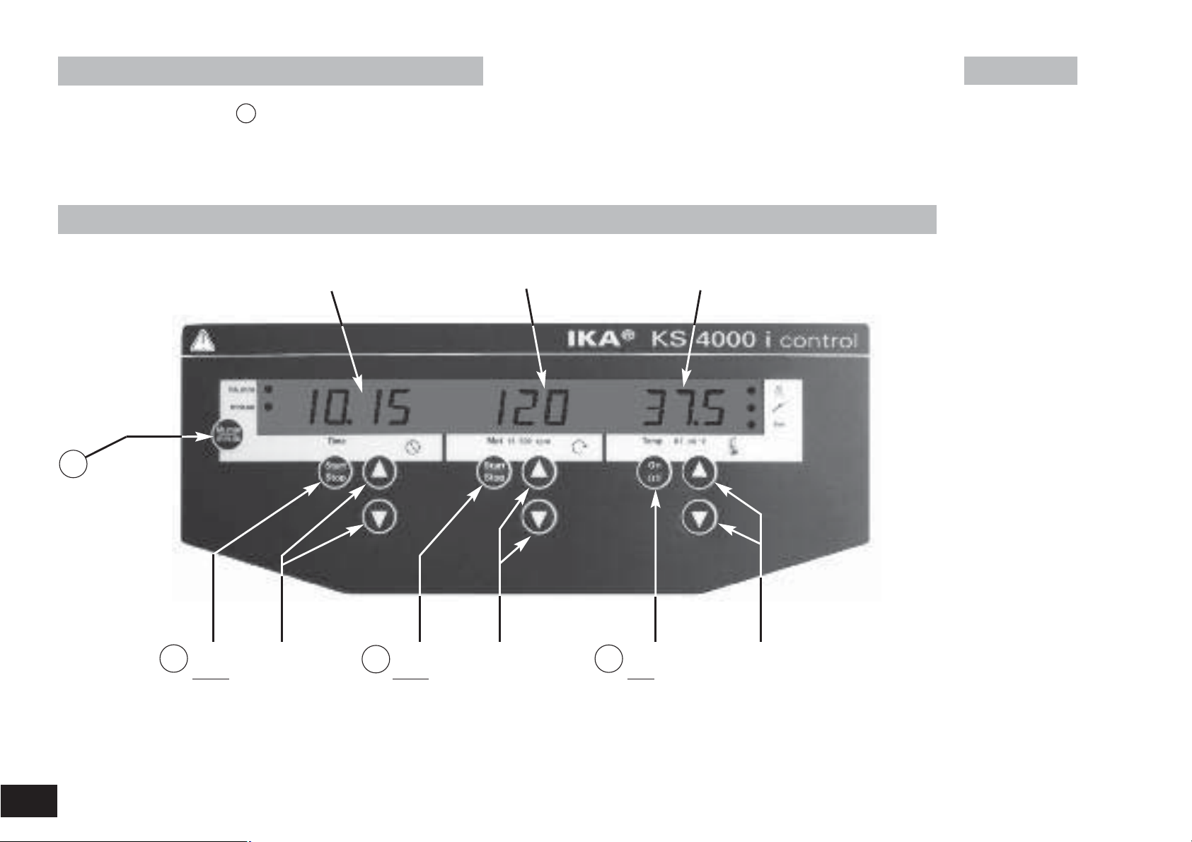
Operator panel and display
1
Shift key
hh : mm
mm : ss
2
Time
Start
Stop
Display
Time
Time
up
down
3
Speed
Start
Stop
Display
Speed
Speed
up
down
Temperature
4
On
Off
Display
Temperature
Temperature
up
down
20
Page 6

Tapping the Start/Stop keys or On/Off key starts the particular functions
Timer
The desired default values can be changed using the or keys.
Use the shift key 1 to switch from hour/minute mode to minute/second mode.
If the elapsed time exceeds the value of 100 hours, the display
switches from hour/minute mode
to hour mode
Only whole hours are displayed in hour mode.
The following sections contain detailed information about the individual functions.
The desired shaking duration is set on the operator panel of the
timer using the Time up/down keys. The shift key can be used to
switch from hour mode to minute mode.
The Time Start/Stop key activates the timer and shaking functions.
When the time is up, the shaking function stops and an acoustic
signal is given off. If the cover is opened before the time is up, the
timer goes to "pause" and the display flashes. If the cover remains
open for more than 15 minutes, the timer switches off and an
error code appears on the display. The shaker no longer starts
when the cover is closed.
If the timer is not activated, the Time display automatically shows
the operating time following the start of the shaking function.
Function Shaking
Function Heating
Press the 3 key to start or stop the shake function. The speed
can be adjusted during operation. The displayed value flashes until
the pre-set speed has been reached.
When the shaking function is started using button 3 , the timer
automatically starts measuring the time until the next switch-off.
Note:
The shaking function can only be started when the cover is closed.
When the cover is opened, the shaker automatically switches off
the shaking and heating functions.
Once the appliance starts, the display indicates the actual value for
the set temperature.
Press the 4 key to start or stop the heating function. The temperature is entered using the Temp up/down keys. In operation, the
temperature is displayed in 0.1 °C steps.
The target value appears approx. every 5 seconds and remains on
the display for 2 seconds.
Note:
The heating function can only be started when the cover is closed.
When the cover is opened, the shaker automatically switches off
the shaking and heating functions.
21
Page 7

Operating modes
External temperature sensor
You can choose between operating modes
and
Appliance does not start up again following power
outage Safety limit value for speed and temperature
adjustable
Appliance starts up again following power outage
Safety limit value for speed and temperature adjustable
Appliance starts up again following power outage
Safety limit values cannot be changed
If external temperature sensor PT1000.60 is connected to the
internal slide-on receptacle, the temperature can be measured at
any place in the medium.
Setting the operating mode
Switch on appliance and simultaneously hold down the Time
Start/Stop key 2 and the shift key 1 .
The display indicates either or depending on the operating mode set (factory default setting A).
(Connector for PT1000.60)
The temperature control of the
heating works automatically with
this display or measuring value.
This is indicated by the lighting up
of the LED next to the temperature sensor symbol
Locate the external
temperature sensor
and the connecting
cable so that the shaking motion is unimpeded and no vessels are damaged or
tipped over.
22
Switching the appliance off and on switches to the next operating
mode
Following the selection of the operating mode, the corresponding
letter appears on the display for 5 seconds, the appliance is ready
for operation.
Calibration - temperature
The appliance is calibrated at the factory.
This function allows the temperature to be calibrated to a desired
value.
This may be necessary, for example, if special sample containers,
their arrangement or external influences (e.g. sunshine) cause the
measuring value for the temperature to be incorrect.
Page 8

Calibration without inserted sensor:
CAL
- Fill Erlenmeyer flask (250ml) with water to the 100ml mark
- Place the Erlenmeyer flask in the centre
- Immerse the sensor of the external measuring device in the
water
- Set the target temperature
- Close the cover and start the Temp function
- Wait until the temperature in the incubation cover has stabilised.
- While holding down the shift key 1 , briefly press the Temp
On/Off key 4 , the
the shift key 1 .
- Set the temperature value read off the external measuring device using the Temp up down keys
- Calibration is complete when you release the shift key
Calibration with inserted sensor:
Calibration with inserted sensor takes place in the same way as
described above.
display appears; keep holding down
Appliance variant KS 4000 ic control
There is a cooler built into this appliance variant.
By using an external cooling unit, the working temperature can be
lowered in relation to the room temperature (depending on the
supply temperature).
The cooler is connected to an external cooling unit (e.g. IKA KV
600) via the plug connection at the back of the appliance. The inlet
and outlet connections are labelled accordingly at the back of the
appliance. To connect the cooling pipes there are two hose
connection pieces included. They can be connected to a hose with
a 10mm interior diameter. The connectors are unlocked by coaxially positioning the unlocking lever and pressing slightly in the
direction of the arrow. By positioning and light pressure in the
direction of the plug, the connectors are locked/connected to the
inlet/outlet plug connections on the housing.
Reset
To restore the factory settings, hold down the Mot key and the
Temp key and press the main switch I/O.
Factory setting: Operating mode A
Upper speed limit 500 rpm
Safety temperature limit 90 °C
Temperature calibration
Drain hose
Unlocking lever
Plug connection
cooler inlet
Plug connection
cooler outlet
23
Page 9

Water is the only coolant that may be used (with antifreeze, e.g. ethylene glycol).
Permissible cooling agents - inlet temperature >3°C
Observe the maximum permissible pressure of 1 bar! As
a safeguard, we recommend using a pressure limiter (e.g.
IKA C25). This is not necessary when using an IKA
KV600.
Accumulated condensate is drained out of the cooler through the
drain hose.
Assembly information for AS 4000.1
Attachments
The following attachments are offered as accessories
AS 4000.1 universal attachment AS 4000.2 bracket attachment
Error codes
An error is indicated by an acoustic signal and an error code is displayed.
24
E.g.:
AS 4000.3 bowl attachment
Note:
During continuous operation, the load may slip, for example, resulting in the appliance becoming excessively unbalanced. To prevent this, there is a motion sensor built in which reduces the
speed gradually once a critical limit has been reached.
The attachments are affixed to the shaking table using the four
clamping screws provided.
Load (standard values)
Load / kg 6 12 15 20
Max. speed / rpm 500 400 300 120
When faults are not specified in the table, you switched the
appliance off and again on.
If faults cannot be eliminated directly, you must perform a
RESET (see "Resetting parameters to the factory settings")!
If the faults still cannot be eliminated, the appliance must be
inspected by a technical service.
Page 10

Error code
Er 3 Temperature inside unit too high • Permitted ambient temperature has Heating off • Switch off the unit. Allow it to cool down
Er 4 Differanceberween setpoint and • Motor seized or overloaded Heating off •
Er 8 The calibration value of the tempe- • Fault in calibration procedure Heating off • Repeat the calibration procedure
Er 14 External temperature sensor, • Short-circuit at temperature sensor Heating off • Check the plug
Er 16 External temperature sensor has • SAFE Temp is set at a temperature Heating off • Allow the unit to cool
Er 17 Temperature sensor - Incubation- • SAFE Temp is set at a temperature Heating off • Allow the unit to cool
Er 26 Difference between the internal • Ventilation slots in incubation room Heating off • Switch off the unit. Allow it to cool down
Er 60 Power outage • Power outage during operation Interruption of heating • Delete the display by pressing the
Description Cause Effect Solution
been exceeded and then switch on again.
• Ventilation slots or fan housing • Clean ventilation slots or fan
blocked housing
• Observe maximum permissible
ambient temperature
Reduce the torque load
actual speeds is too large
rature sensor is outside the limit •
value • EPROM switching error
short-circuit plug • Substitude the temperature sensor
exceeded the SAFE Temp lower than the actual temperature on •
room has exceeded the lower than the actual temperature on •
SAFE Temp the external t
contro and safety temperature blocked and then switch on again.
sensors too large • Radial-flow fan does not rotaded • Check fan or ventilation slots and
Value was incorrectly stored to memory
• Short-circuit in connecting cable
or on temperature sensor
the external t
• Fault in the control or safety clean if necessary
temperature sensors
emperature sensor
emperature sensor
or shaking function shift key
(load)
• Reduce the setpoint speed
Set the SAFE Temp at a higher temperature
Set the SAFE Temp at a higher temperature
25
Page 11

Error code
PC 1 In remote operation (PC) with • PC does not send data during the Heating off • Change the watchdog time
PC 2 In remote operation (PC) with • PC does not send data during the The setpoint temperature • Change the watchdog time
Description Cause Effect Solution
watchdog function 1 enabled: watchdog time Motor off • Send data from the PC within the
No communication between • The connection/cable to the PC is watchdog time
PC and unit broken • Check the connector cable and plug
watchdog function 2 enabled: watchdog time is set to the WD safety • Send data from the PC within the
No communication between temperature watchdog time
PC and unit • The connection/cable to the PC is The setpoint speed • Check the connector cable and plug
broken is set to the WD safety
speed
Interface and outputs
Configuration
The unit can be controlled from an external PC (using the dedicated software labworldsoft) via the RS 232 C serial interface
fitted to the unit.
To increase safety when controlling the shaking unit from
a PC, enable the watchdog function for monitoring the
continuous serial data flow (see section watchdog function)
• The functions of the inteface lines between laboratory instrument and automation system are selected from the
specfied signals of the EIA-standard RS 232 C, corresponding
with DIN 66020 Part 1. The allotment of the bushing can be
taken from illustration.
• For the electrical properties of the interface lines and for the
allotment of the signal status, standard RS 232 C, corresponding with DIN 66259 Part 1 applies
(see capture PC 2.1 cable).
• Transmission method: Asynchronous signal trans-
mission in start-stop-operation
• Mode of transmission: Fully Duplex
• Character format: Character imaging acc. to data
format DIN 66022 for startstop-operation. 1 start bit;
7 character bits; 1 parity bit
[(straight (even)]; 1 stop bit.
• Transmission speed: 9600 bit/s
• Access method
Instruction syntax
Here applies the following:
• The instructionsare generally sent from the processor
(master) to the laboratory instrument (slave).
• The laboratory instrument exclusively sends on demand of
the processor. Even error codes cannot be spontaneously
communicated from the laboratory instrument to the processor (automatic system)
•Instructions and parameters as well as subsequent para-
meters are separated by at least o n e blank.
: Data communication from
shaker to computer is only
possible on demand of the
computer.
(Code: hex 0x20)
26
Page 12

• Each individual instruction including parameters and data as
well as each reply are terminated with CR LF (Code: hex
0x0D and 0x0A) and have a maximum lenght of 80 characters.
• The decimal separator in a floating point number is the point.
(Code: hex 0x2E)
The above statements largely correspond with the recommendations of the NAMUR-Assocation (NAMUR-recommendations for the design of electric plug connections for the analog
and digital signal transmission to labortory - MSR individual
units. Rev. 1.1).
Overview of the NAMUR-instructions
Abbreviations:
X,y = numbering parameter (integer number)
m = variable value, integer
n = value of variable, floating point number
X = 1 Pt1000 medium temperature (external temperature
sensor)
X = 2 temperature (incubations room)
X = 3 safety temperature
X = 4 speed
X = 6 safety speed
X = 50 Pt1000.60 medium temperature sensor offset in K
(-5.0 <= n <=+5.0)
X = 52 incubations room temperature sensor offset in K
(-5.0 <= n <=+5.0)
NAMUR instuctions
IN_NAME Input description name
IN_PV_X Reading the real value
X=1;2;3;4;
IN_SOFTWARE Input software ID number
IN_SP_X Reading the set rated value
X=1;2;3;4;6;12;
42;50;52;53;
IN_TYPE Input laboratory unit ID
OUT_NAME name
OUT_SP_12@n Setting the WD safety temperature with the
OUT_SP_42@n Setting the WD safety speed with the
OUT_SP_X n Setting the rated value to n
X=1;2;4;50;52
OUT_WD1@m Watchdog mode 1: When a WD1 event occurs,
OUT_WD2@m Watchdog mode 2: When a WD2 event occurs,
RESET Switching off the instrument function.
Function
date, version
Output description name. (Max. 10 characters,
default: KS4000 ic)
echo of the set value
echo of the set value
the heating and shaking functions are shutdown
and message PC 1 is displayed.
Set the watchdog time to m (20...1500) seconds,
with echo of the watchdog time. This instruction
starts the watchdog function and must be sent
within the set watchdog time.
the speed setpoint will be set to the WD safety
setpoint speed and the temperature setpoint
will be set to the WD safety setpoint temperature. The PC 2 warning is displayed.
The WD2 event can be reset with OUT_WD2@0resetting also blocks the watchdog function. Set
the watchdog time to m (20...1500) secondes,
with echo of the watchdog time. This command
starts the watchdog function and must be sent
within the set watchdog time.
27
Page 13

START_X Starting the instrument’s (remote) function
X=1;2;4 (Display additionally: PC)
STATUS Display of status
1S: mode of operation A
2S: mode of operation B
3S: mode of operation C
S0: manual opration without fault
S1:
Automatic operation Start (without fault)
S2:
Automatic operation Start (without fault)
<0: error code: (-1)
- 1: error 1
- ... (see table)
-31: error 31
-83: wrong parity
-84: unknown instruction
-85:
wrong instruction sequence
-86: invalid rated value
-87: not sufficient
storage space
STOP_X Switching off the instrument
X=1;2;4
“Watchdog” function, monitoring the serial
data flow
The following applies to situations where the watchdog function is enabled (see Namur instructions). If no new transmissions of these commands from the PC take place within the preset watchdog time, the heating and shaking functions will be
shutdown according to the watchdog mode selected or will be
controlled using the preset setpoints. An operating system
crash, a PC power failure or a fault in the connecting cable to
the instrument can cause an interruption in data transmission.
“Watchdog”– Mode 1
If an interruption in data transmission occurs which is longer
than the preset watchdog time, the heating and shaking functions will be shutdown and the error message PC 1 will be displayed.
on. Variables set with OUT_SP_X are maintained. Contains the instruction RMP_STOP.
(Display additionally: PC)
- (remote) funkti-
“Watchdog”– Mode 2
If an interruption in data transmission occurs which is longer
than the preset watchdog time, the speed setpoint value will
be set to the WD safety speed setpoint and the temperature
setpoint will be set to the WD safety temperature setpoint.
The PC 2 warning message will be displayed.
Connections between shaking instrument and external
devices
PC 1.1 Cable
Cable PC 1.1 for connection to the 9-pin socket on the computer.
Maintenance and cleaning
The shaker KS 4000 i control and KS 4000 ic control
ace-free. It is subject only to the natural wear and tear of components and their statistical failure rate.
Examine in regular intervals the functionality and the correct
attachment of the two gas-filled supports!
When ordering spare parts, please give the manufacturing
number shown on the type plate, the machine type and
the name of the spare part.
Please send in equipment for repair only after it has been cleaned and is free from any materials which may constitute a
health hazard. Use only cleansing agents which have been
is mainten-
28
Page 14

approved by IKA to clean IKA devices.
To remove use:
Dyes isopropyl alcohol
Construction materials
Cosmetics water containing tenside / isopropyl alcohol
Foodstuffs water containing tenside
Fuels water containing tenside
For materials which are not listed, please request information
from IKA. Wear the proper protective gloves during cleaning of
the devices.
Electrical devices may not be placed in the cleansing agent for
the purpose of cleaning.
Before using another than the recommended method for cleaning or decontamination, the user must ascertain with the
manufacturer that this method does not destroy the instrument.
Collecting tray with drain hose (for picture see below)
(applies to KS4000 i control and KS4000 ic control)
In the event of glass breakage, leaking liquid is collected by the
collecting tray below the shaking table and guided to the drain
hose via a drain at the rear.
water containing tenside / isopropyl alcohol
1. Remove drain hose
from bracket
Cleaning of the collecting tray:
Cleaning the Plexiglas cover:
- Do not dry wipe.
- Do not use abrasive materials.
- Do not use solvents.
Clean dusty surfaces with warm water, detergent and a soft
cloth.
We recommend the anti-static plastic cleaner “AKU” by Burnus
GmbH, Darmstadt.
For disinfecting, only use products prescribed by the manufacturer specially for use on Plexiglas.
- four countersunk
head screw at the
top side of the
shaking table
loosen
- shaking table
upward remove
2. Place drain hose
in laboratory drain
29
Page 15

Accessories
1RWH
AS 4000.1 Universal attachment
AS 4000.2 Holding bracket attachment
AS 4000.3 Dish attachment
PC 1.1 Adapter
Technical data
Design voltage VAC 230±
or VAC 115±
Design frequency Hz 50/60
Heating power W 1000
Input power W 1120
Speed range rpm 10 - 500
Heating temperature range °C RT +5 .... 80
Temperature constancy K 0,1
(200ml water at set
point T=37°C, RT 25°C)
Temperature sensor K ≤±(0,15 + 0,002 x ITI)
PT1000.60 - variation
DIN EN 60751 Kl.A
Permitted duration of operation
Permitted ambient temperature
Permitted relative humidity
Protection class acc. DIN EN 60529
Protection class
Overvoltage category II
Contamination level 2
Operation at a terrestrial altitudemmax. 2000 above sea level
% 100
°C +15 at +32
% 80
10%
10%
IP 30
I
Protection at overload Temperature sensor
in motorwinding
Fuses on apparatus plug
115V A T16A (Id.Nr. 37 368 00) 2x
230V T10A (Id.Nr. 27 554 00) 2x
Radius orit mm 20
Shaking motion orbital
Max. load kg 20
Dimensions (B x H x T) mm 580 x 750 x 520
Weight (i control) kg 50
Weight (ic control) kg 55
Speed setting Digital
Button on front side
Dissolution of adjusting rpm 1
Speed display LED - Display
Max. speed deviation from idle
Temperature settiung Digital
Button on front side
Dissolution of adjusting K 0,1
Temperature display LED - Display
Time setting Digital
Button on front side (altern. Min/Std)
Time display LED - Display
Interface RS 232 C
KS 4000 ic control
Temperature range °C 12 - 80
(inlet T>3°C)
1
&RPSOLHVWR(1VXEMHFWWRFRQGLWLRQDOFRQQHFWLRQ
=PD[ ,IQHFHVVDU\FRQVXOW\RXUHOHFWULFLW\VXSSOLHU
% ±1
1 - 999 hh:min/min:sec
30
Drive Speedcontrol
asynchronous motor
Subject to technical changes!
 Loading...