

Page 1

43 459 00 a
IKA® C 6000 global standards
IKA
®
C 6000 isoperibol
052014 Reg.-No. 4343-01
Operating instructions EN
Page 2

Page 3

Source language: German
EN
Contents
Page
CE Declaration of conformity 04
Explication of warning symbols 04
Safety instructions 05
Correct use 07
User instructions 07
System features 07
Warranty and liability 08
Transport and storage 08
Transport and storage conditions 08
Unpacking 09
Scope of supply 09
Description of system components 10
®
C 6000 calorimeter global standards/isoperibol 10
IKA
Hoses 11
Commissioning 11
Place of installation 11
Connection to the condenser 12
Connection to the water 12
Connection to the oxygen supply 13
Connection to the mains power supply 13
Connection of peripherals 14
On/off switch 15
Display and operating elements 16
Explanation of the screen display 16
Working with the IKA® C 6000 global standards/isoperibol calorimeter 20
Switching on the device 20
System test 20
Switching off the device 21
The standard calorimetric procedure 22
- Calorifi c value determination 22
- Corrections 23
- Note on the sample 24
- Complete combustion 25
- Calibration (only IKA® C 6000 global standards) 25
- Calibrating 26
- Instructions on calibration 26
Preparation for measurement 27
Charging the decomposition vessel 29
Calorimetric measurement without automatic decomposition vessel detection 29
Starting the measurement 30
Evaluation 32
Menu (main overview) 33
Library 34
Method of operation, decomposition vessels and calibration 35
Servicing the decomposition vessel 38
Contents
3
Page 4

Other Settings 38
Evaluation 38
Measurement 39
Ignition aids 40
Combustion aid 41
Balance 41
Printer 42
Other 42
Help and servicing system 44
Displaying / hiding the sample rack 46
Cleaning 48
Cleaning the system 48
Cleaning the fi lter 48
Troubleshooting 49
Fault rectifi cation 51
Checks 55
Accessories and consumables 56
Accessories 56
Technical data 57
Technical data IKA® C 6000 global standards 57
Technical data IKA® C 6000 isoperibol 59
EC-Declaration of conformity
We declare under our sole responsibility that this product corrosponds to the regulations 2006/95/EG, 2004/108/EG and
2011/65/EU and conforms with the standards or standardized documents EN 61010-1:2010, EN 61010-2-051:2003 and
EN 61 326-1:2006.
Explication of warning symbols
General hazard
This symbol indicates information which is essential for the safety of your health.
DANGER
WARNING
Failure to observe this information can cause damage to health and injuries.
This symbol indicates information which is important for ensuring that the
appliance functions without any technical problems.
Failure to observe this information could damage the calorimeter system.
ATTENTION
Contents
This symbol indicates information which is important for ensuring that calorimetric measurements are performed effi ciently and for using the calorimeter system.
Failure to observe this information can result in inaccurate measurements.
4
Page 5

Safety instructions
Read the operating instructions in full before
starting up and follow the safety instructions.
Keep the operating instructions in a place where
they can be accessed by everyone.
Ensure that only trained staff work with the
appliance.
Follow the safety instructions, guidelines,
occupational health and safety and accident
prevention regulations.
The IKA® C 6000 global standards/isoperibol
calorimeter system may be used only in conjunction
with the decomposition vessels C 6010 or C 6012
for determination of the calorifi c values of solid
and liquid substances to national and international
standards (such as DIN 51900, BS 1016 T5, ISO
1928, ASTM 5468, ASTM 5865 and ASTM 4809).
The maximum extra energy added to the
decomposition vessel must not exceed 40,000 J
(select the test mass accordingly). The permitted
operating pressure of 230 bar (23 MPa) must not
be exceeded. The maximum permitted operating
temperature must not exceed 50 °C.
When burning substances containing metals,
ensure that the maximum energy input is not
exceeded!
Only fi ll the decomposition vessel with oxygen to a
maximum pressure of 40 bar (4 MPa). Check the
pressure setting on the pressure reducer for your
oxygen supply. Perform a leakage test before each
combustion process (see section „Leaktightness
testing“).
with a low vapour pressure (e.g. tetramethyl
dihydrogen disiloxane) must not directly touch the
cotton thread!
DANGER
example, is possible in the inner wall of the
decomposition vessel.
Observe the accident prevention requirements
applicable to the activity and the work station.
Wear your personal protective equipment.
When handling combustion samples, combustion
residue and auxiliary materials, please observe
the relevant safety regulations. The following
materials, for example, could pose a risk:
– corrosive
– highly fl ammable
– explosive
– bacteriologically contaminated
– toxic
Please observe the relevant regulations when
handling oxygen.
Warning: oxygen as a compressed gas is oxidising;
intensively aids combustion; can react violently
with fl ammable materials.
DANGER
Tubes and screwed joints for oxygen must be kept
free of grease.
Furthermore, toxic combustion
residue in the form of gases,
ashes or condensation, for
Do not use oil or grease!
Some materials tend to explode when combusted
(e.g. due to formation of peroxides), which could
cause the decomposition vessel to crack. The
IKA® C 6000 global standards/isoperibol
calorimeter may not be used for testing
explosive samples.
If the burning behaviour of a material is unknown,
it must be tested before combustion in the
decomposition vessel (risk of explosion). If you are
burning unknown samples, leave the room or
keep your distance from the calorimeter.
Benzoic acid may only be combusted in its pressed
form! Flammable dust and powder must be fi rst
pressed. Oven-dry dust and powder such as splints,
hay, straw etc. explode when combusted! Always
wet these materials fi rst! Highly fl ammable liquids
Safety instructions
Combustion gases are hazardous to
health, therefore the venting hose must be
connected to a suitable gas cleaning system
or extraction system.
At the end of the work period, close the main
valve for the oxygen supply.
Perform servicing work only when the equipment
is depressurised.
When using stainless steel crucibles thoroughly
check their condition after each experiment. If the
material gets thinner, the crucible may catch fi re
and damage the decomposition vessel. Crucibles
must not be used for more than 25 combustions
for safety reasons.
5
Page 6

The decomposition vessel is manufactured
in accordance with the directive for pressure
equipment 97/23/EC. This is indicated by the CE
symbol with the ID number of the notifi ed body.
The decomposition vessel is a category III pressure
device. The decomposition vessel has undergone
an EC prototype test. The CE declaration of
conformity confi rms that this decomposition
vessel corresponds to the pressure device
described in the EC prototype test certifi cate. The
decomposition vessel has undergone a pressure
test with test pressure of 33 MPa and a leakage
test with oxygen at 3 MPa.
Refer also to the operating instructions for the
C 6010/ 6012 decomposition vessel, see chapter
„maintenance of the decomposition vessel“.
Decomposition vessels are experiment autoclaves
and must be tested by a technical expert after
each use.
We recommend that you send the
decomposition vessel to our factory for
inspection, and if necessary, repair after
1000 tests or after one year or sooner
depending on use
A pressure test must be performed after a
decomposition vessel has reached or exceeded the
recommended number of ignition cycles. Once
the pressure test has been performed a release
code can be entered to enable the decomposition
vessel to be used for further measurements (see
the sections “Maintenance of the Decomposition
Vessel” and “Inputting a Service Code”).
The warning message will then disappear!
Note: You can then continue to use the device /
decomposition vessel.
Contact the IKA® Service Department to perform
the pressure test. Comply with the safety
instructions in this respect. The user will be given
specifi c instructions on the relevant screen.
Individual use is understood here to include a
series of experiments performed under roughly
the same conditions in terms of pressure and
temperature. Experiment autoclaves must be
operated in special chambers
The decomposition vessels must undergo repeated
tests (internal tests and pressure tests) performed
by the technical expert. The frequency of these
tests is to be determined by the operator on the
basis of experience, type of operation and the
material used in the decompositionvessel.
The declaration of conformity becomes invalid if
mechanical modifi cations are carried out to the
experiment autoclaves or if tightness can no longer
be guaranteed as a result of major corrosion (e.g.
pitting by halogens).
In particular the threads on the pressure vessel and
the union nut are subject to considerable stress
and must therefore be checked regularly for wear.
The condition and function of the seals must be
checked and ensured by way of a leakage test
(see the operating instructions for the C 6010/
6012 decomposition vessel, section „Leaktightness
testing“).
For the purposes of these operating instructions a
technical expert is someone
1. who guarantees to conduct the tests properly
on the basis of his training, knowledge and
experience gained through practical work,
2. who is suffi ciently reliable,
3. who is not subject to any instructions in terms
of the test activity,
4. who has suitable test equipment if necessary,
5. who can provide appropriate proof of the
requirements listed in 1.
National directives and laws must be
observed for operating pressure vessels!
Anyone operating a pressure vessel must keep it in
a proper condition, operate it properly, supervise
it, carry out the necessary maintenance and repair
work immediately and implement the safety
measures required in the circumstances.
Pressure vessels must not be used if they have
defects which could pose a risk to staff or third
parties.
If the maintenance, and especially the pressure
testing, is not performed or is performed
incorrectly, there is a risk the decomposition vessel
may burst or an uncontrolled internal fi re may
occur at the electrodes which could burn away
the seals (oxyacetylene torch effect), thus posing
a risk to life and limb.
Only technical experts may perform pressure
tests and service work on the decomposition
vessel.
Safety instructions
6
Page 7

Correct use
The IKA® C 6000 global standards/isoperibol
calorimeter system is used for calorifi c value
determination of solid and liquid substances.
This is done by placing a known quantity of a
substance in a decomposition vessel which is
surrounded by a water jacket. The sample is then
combusted in an oxygen atmosphere . The calorifi c
value of the sample can then be calculated from
the resulting increase in temperature, the sample
User instructions
In this chapter you can fi nd out how to work
through these Operating Instructions most
effectively to be able to work reliably with the
calorimeter system.
The instructions in the section „Safety
instructions“ must be complied with.
The chapters are designed for you to work through
them in order.
The section „Transport, storage“ is relevant for
system reliability and for ensuring high measuring
accuracy. The section „Description of system
components“ describes the system components,
mass and the known thermal capacity of the
overall system.
®
The IKA
calorimeter system is subject to the Pressure
Vessel Directive 97/23/EC. Comply with the safety
instructions accordingly.
For adaptation to individual laboratory tasks, use
original IKA® consumables and accessories.
and the section „The standard calorimetric
procedure“ describes the essentials of calorimetry.
The calorimeter system is ready to perform
measurements once you have completed the
procedures in the section „Setting up and
commissioning“: - „Preparing a measurement“
and „Starting a measurement“.
Numbers 1, 2, 3 etc. indicate operating instructions
in the following sections. These must always be
carried out in the specifi ed sequence.
C 6000 global standards/isoperibol
System properties
The calorimeter system IKA® C 6000 global
standards/isoperibol is routinely used for determination of gross calorifi c values of solid and
liquid substances. The accessories of the system
ensure customized adaptation to laboratory tasks.
The system is characterized by the following
features:
• Relieves you of routine tasks through automated
measurement procedure
• Integral oxygen fi lling/degassing
• Automatic detection of decomposition vessel
• Operation without the cooling unit: Connection
to a water faucet with the pressure valve IKA
C 25; temperature range 12 °C upto 27 °C;
water consumption per measurement about 4 l;
water pressure max. 1 bar upto 1,5 bar.
®
• Operation with active cooling unit 17-27 °C
(e.g. IKA® KV 600; optional)
• Measurement and calculation of gross calorifi c
value according to DIN 51900, ISO 1928, ASTM
D240, ASTM D4809, ASTM D5865, ASTM
D1989, ASTM D5468, ASTM E711
• Calculation of net calorifi c value according to
DIN 51900, ASTM D240, ASTM D4809, ASTM
D5865, ASTM D1989, ASTM D5468, ASTM
E711
• Measurement range: max. 40.000 J (This
corresponds to an increase in temperature in
the decomposition vessel of approx. 5 K).
• PC-operation of one or several calorimeters
(Software CalWin®)
• A sample rack can be connected
• USB printer port is available
Correct use
7
Page 8

• Operating mode based on the adiabatic,
isoperibolic or dynamic principle at 22 °C, 25
°C or 30 °C (the beginning temperature of the
water in the inner vessel) depending on the
cooling water temperature.
Cooling water Mode of operation Mode of operation
temperature C 6000 global standards C 6000 isoperibol
12 °C bis 20 °C Adiabatic 22 °C Isoperibolic 22 °C Isoperibolic 22 °C
Dynamic 22 °C Dynamic 22 °C
20 °C bis 23 °C Adiabatic 25 °C Isoperibolic 25 °C Isoperibolic 25 °C
Dynamic 25 °C Dynamic 25 °C
23 °C bis 27 °C Adiabatic 30 °C Isoperibolic 30 °C Isoperibolic 30 °C
Dynamic 30 °C Dynamic 30 °C
Differences between the room temperature
and working temperature have an infl uence on
accuracy in dynamic mode; as a result, the working
temperature should always be kept similar to the
room temperature.
Warranty and liability
In accordance with IKA® warranty conditions, the
warranty period is 12 months. For claims under
the warranty please contact your local dealer. You
may also send the machine direct to our factory,
enclosing the delivery invoice and giving reasons
for the claim. You will be liable for freight costs.
Please read these operating instructions carefully.
®
IKA
only consider themselves to be responsible
for the safety, reliability and performance of the
appliance when
• the appliance has been operated in accordance
with the operating instructions,
• only persons authorised by the manufacturer
interfere with the appliance,
• only original parts and original accessories are
used for repairs.
Transport and storage
Transport and storage conditions
The warranty does not cover worn out parts, nor
does it apply to faults resulting from improper use,
insuffi cient care or maintenance not carried out in
accordance with the instructions in this operating
manual.
The calorimeter system may be opened only by
an authorised Service Agent or Customer Service
Centre.
If service is required, we recommend that you
contact our customer service department
Furthermore, we refer you to the applicable safety
conditions and accident requirements.
®
is not responsible for damages or costs
IKA
resulting from accident, improper use of the
device or impermissible modifi cations, repairs or
renovations.
The system must be protected against mechanical
impact, vibrations, dust deposits and corrosive
ambient air during transportation and storage. It is
also important to ensure that the relative humidity
does not exceed 80%.
The appliance must be completely emptied before
storing and transportation.
In case of repair the device has to be cleaned and
free from any materials which may constitute a
health hazard.
User instructions
For this use the „certifi cate of compliance“, download the form from the IKA® website www.ika.
com.
If you require servicing, return the appliance in its
original packaging. Storage packaging is not suffi
cient. Please also use suitable transport packaging.
8
Page 9

Unpacking
Please unpack the system components carefully
and check for any damage. When you unpack the
equipment, check for any damages which may
have occurred during transportation.
In the case of any damage a fact report must be
sent immediately (post, rail or forwarder).
Scope of supply
Calorimeter IKA® C 6000 global standards/isoperibol
• Calorimeter IKA® C 6000 global standards/isoperibol
• Attachment set
• Stylus for touch screen operation
• Discharge hose (1.5 m)
• Connection tube O
• Venting hose
• Mains connection cable
• Warranty card
• Water infl ow pipe
• Water return pipe
• Operating instructions
2
Transport, storage, place of installation
9
Page 10

Description of system components
Calorimeter IKA® C 6000 global standards/isoperibol
Interfaces
Lift
Decomposition vessel
Stylus for
operating the
touch screen
Touch Screen
Water fi lter
Mains power supply
Water Oxygen
10
Description of system components
Page 11

Hoses
• Discharge hose
(empty)
• Infl ow pipe
(in)
• Return pipe
(out)
• Venting hose
(out)
Condenser
C 6000
C 6000
C 6000
• O2 connection tube
(in)
Commissioning
Place of installation
A constant ambient temperature is an important
requirement for ensuring the high measuring
accuracy of the system. The following conditions
must therefore be fulfi lled at the place of
installation:
•
No direct solar radiation
• No draughts (e.g. beside windows, doors, air
conditioning)
• Suffi cient distance to radiators and other heat
sources
• The minimum distance between the wall and
the rear side of the device must be at least 25
cm.
M8x1
M8
M6
C 6000
For operation of the system the following must be
available at the place of installation:
- A power supply corresponding to the nameplates
on the system components,
- An oxygen supply (99.95 % pure oxygen, quality
3.5; pressure 30 bar) with pressure gauge.
A shut-off valve for the oxygen supply must be
installed. Observe the instructions on handling
oxygen given in the chapter „Safety instructions“.
Please read these operating instructions carefully.
®
consider themselves responsible for the
IKA
safety, reliability and performance of the appliance
only when
• the device has been operated in accordance
with the operating instructions,
• The system must not have laboratory hardware
such as shelves, wire ducts, ring lines, etc.
installed above it.
• The (constant) room temperature should be
around 20 °C ... 25 °C.
• The system must be set up on a horizontal
surface.
Description of system components
• the specifi cations for the place of
installation have been met.
Do not use distilled or demineralized water
(increased risk of corrosion)! Fill the cooler
according to the cooler operating instructions. is
recommended in drinking tap water quality. Mix
in (max. 1 ml for 4-5 l of water) of the supplied
water additive. Thus, the durability of the water is
improved.
11
Page 12

Connection to the condenser
Rear view without hoses attached
Make sure the fi lter casing is always
securely closed (see „Servicing and
cleaning the fi lter“)!
Insert the infl ow pipe into the „IN“
port until it clicks home. Connect the
other end of the pipe to the „OUT“
port of the condenser (water pressure
max 1.5 bar).
Insert the return pipe into the „OUT“
port until it clicks home. Connect the
other end of the pipe to the „IN“ port
of the condenser.
Connection to the water
Operatrion is only allowed with the
pressure valve IKA® C 25!
The IKA® C 25 pressure valve is
absolutely essential on the water
faucet for operation of the calorimeter,
The connection „EMPTY“ is intended
only for emptying the device, e.g.
for transport purposes. In normal
operation the discharge hose need not
be inserted!
and it must be preset to an output
pressure of approximately 1.5 bar.
The valve is installed into the line of
the water connection, see operating
instruction IKA
®
C 25.
Commissioning
12
Page 13

Connecting the oxygen supply
Insert the O2 connection tube into the calorimeter
„IN“ port until it clicks home and connect the free
end to the pressure reducer, using the adapters
supplied if necessary. IKA® C 29. Removal entails
the same operations performed in the reverse
sequence.
Note: The O2 connection tube can be removed
only after it has been depressurised.
Screw the venting hose to the screw coupling
(8 AF) on the calorimeter and position the free
end under the extractor hood or connect it to a
gas washing device. Comply with the applicable
safety regulations in this respect.
IKA® C 29
The venting hose discharges the combustion
gases from the decomposition vessel after every
combustion trial. When laying the venting hose
ensure that it is not crushed or kinked.
Connection to the mains power supply
Check that the available mains power supply
matches the mains power supply particulars listed
on the rating plate.
O2 connection tube IN
max. 4 MPa
Venting hose
Combustion gases are
DANGER
therefore the venting hose must be
connected to a suitable gas cleaning system
or extraction system.
hazardous to health,
Commissioning
13
Page 14

Connection of peripherals
Standard setting : Baud rate: 9600
Note: While the peripheral devices are being connected, they and the calorimeter must be
turned-off on the mains power switch!
RS232 PC: Serial connection for controlling the calorimeter using CALWIN or operating
with serial printer C1.50.
Data bits: 8
Stop bits: 1
Parity: none
Handshake: none
RS232 BALANCE: Interface for connecting scales (Mettler, Ohaus, Sartorius, Kern)
Standard setting : Baud rate: 1200
Data bits: 7
Parity: odd
Stop bits: 1
Handshake: none
ETHERNET:
USB-DEVICE: USB interface (only for service).
USB-HOST: Interface for connection of a printer or with a USB mouse.
SAMPLE-RACK: Interface for connection of the C 5020 sample rack.
Network connection for data transfer via the network, e.g. to a network printer.
Commissioning
14
Page 15

On/off switch
The device is switched on and off via
the on/off switch located on the righthand side.
Switch the device off at the on/off
switch.
� Lift moves upwards.
Switch the appliance off only by using
the menu commands.
� Lift moves downwards.
Data may be lost if the
ATTENTION
other than by following the menu commands.
Note: Switch the device off at the on/off
switch only when directed to do so by
the menu command.
appliance is switched off
Commissioning
15
Page 16

Display and operating elements
Explanation of the screen display
Schematic representation of he display components
After the IKA® C 6000 global standards/
isoperibol calorimeter has been switched on,
the touch screen display is active and can be
operated using the stylus or fi nger.
A
G
I
Pos. Designation
A Tab
C Arrow symbol, tabs
D Arrow symbol, vertical scroll bar
E Vertical scroll bar
F Info line
G Arrow symbol, horizontal scroll bar
H Horizontal scroll bar
I Control button
C
D
E
D
F
G
H
Other view-based presentations of display components are described in the relevant section.
16
Display and operating elements
Page 17

List display
The contents of the screen display are often
distributed over several tabs. You can switch
between tabs at any time by clicking on them.
Thus for instance the screen display during the
calorimetric standard procedure consists of the
three views „Measurements“, „Device“ and
„Graphics“.
Status symbols
Green tick
Measurement completed but not yet evaluated, or selection acknowledgement.
Pocket calculator
Measurement completed end evaluated, evaluation inputs can no longer be changed.
Blank tick
Measurement prepared but not yet performed.
Report
fi eld
Yellow X
Field property not selected, or cancelled before ignition.
Red X
Cancellation after ignition.
Circle
Measurement selected.
List displays and report fi elds have scroll bars. Clicking on the pale areas of the scroll bar scrolls the
list display or report fi eld. Clicking in the dark area
and dragging it allows you to move continuously
through the display, as does clicking on the arrow
symbols and maintaining the selection.
Display and operating elements
Note: Greyed-out fi elds cannot be selected.
17
Page 18

The view „Graph“ shows the temperature by
time.
The most important actions available at any point
in time are gathered together as clickable buttons
along the bottom edge of the screen.
Switch
Selection
box
Switch
To initiate an action it is suffi cient to click on one
of the discrete areas showing the relevant images
or text. For instance during the „Preparation for
measurement“ dialogue the most important actions are explained below.
Weighted sample
Permits manual input of a weight value using the
virtual keyboard.
Calibration
Selection fi eld for marking a calibration (on/off).
Decomposition vessel
Manual selection box when decomposition vessel
detection is inactive.
Name
Alphanumeric editable fi eld
User
Alphanumeric editable fi eld
Properties
Alphanumeric editable fi eld
IKA® thread
Selection box which allows a selection list to be
opened.
Display and operating elements
18
Page 19

Weighted sample
Input of a numerical value, such as weighted sample:
The entire area with the exception of the „Balance“ button is available to be clicked here. A
numerical virtual keyboard is opened and can be
used to input the value:
After the virtual keyboard has been closed with
„OK“, the value in the input fi eld is loaded. Alternatively, clicking on the „Balance“ button automatically loads a value from a connected balance.
Selection box
Shift key for upper and lower case letters and
special characters
Input of an alphanumeric value, such as
„Designation“ :
Here again the entire area is available to be clicked.
A complete virtual keyboard is opened.
Note: The maximum input is 23 characters.
After the virtual keyboard has been closed with
„OK“, the value in the input fi eld is loaded.
Select from a selection box, e.g. for the ignition aid:
Display and operating elements
After the selection box has been clicked, a list of
the options is displayed. The option that is clicked
is selected.
Single selection fi eld, such as calibration :
Clicking on the entire area allows the prepared
measurement to be marked as a calibration.
19
Page 20

Working with the IKA® C 6000 global standards/isoperibol calorimeter
Switching on the device
®
The IKA
switched on with the On/off switch. The cover
opens automatically. A start screen appears for
about 30 seconds, during which the hardware is
initialised and the software is loaded.
System test
The system test is performed automatically every time the IKA
switched on.
During the system test the start screen is shown
again; clicking on the „Show details“ button provides detailed information.
C 6000 global standards/isoperibol is
®
C 6000 global standards/isoperibol is
Safety instructions regarding information on and
activation of the calorimeter are then shown on
the IKA
®
Homepage.
The system test includes the following steps:
- Testing the external water circuit with the circulation pump and heater (approx. 30 to 45
seconds).
- Testing the internal water circuit with the condenser and water supply, plus the heater once
again (approx. 30 to 45 seconds).
- Testing whether the temperature of the cooling
waters is correct for the selected function of the
IKA® C 6000 global standards/isoperibol. (ap-
prox. 60 to 180 seconds).
If any one of these steps is not performed successfully, the system test stops with an error message. After all the components have been checked the system test can be restarted the same as
after a manual cancellation. To do this, press the
„Restart“ button.
With the system test in standby, no measurements can be made. However it is possible to select some menu options.
20
Working with the IKA® C 6000 global standards/isoperibol calorimeter
Page 21

If the cooling water conditions are not correct for
the selected function of the IKA® C 6000 global
standards/isoperibol, you can select a different
function from those currently available. Make sure
however that the system conditions are stable.
The following are the default modes that are set:
- Adiabat 22
- Isoperibol 22
If the system is changed to a different function it
must be recalibrated.
(IKA® C 6000 global standards)
(IKA® C 6000 isoperibol)
Switching off the device
First commissioning
At fi rst commissioning you must register a decomposition vessel:
To do this, press „Menu on“ button.
Select the „Function...“ menu item.
Select the „New decomposition vessel“ tab.
Follow the instructions on page 37.
„End“: This saves the measurements taken during the day; the cover of the calorimeter is
closed and the software shut down. After this,
I
switch off the calorimeter and all the accessories.
Never switch the device off without previously having run „End“, otherwise data
may be lost!
Working with the IKA® C 6000 global standards/isoperibol calorimeter
21
Page 22

Die kalorimetrische Standardprozedur
Determining the calorifi c value
Test condition
Combustion is carried out in a calorimeter under
specifi c conditions. The IKA® C 6000 global
standards/isoperibol is fi lled with a weighed
fuel sample, the fuel sample is ignited and the
temperature increase in the calorimeter system
measured.
The specifi c calorifi c value of the sample is
calculated as follows:
• Weight of fuel sample
•
Heat capacity (C-value) of calorimeter system
•
Calculated temperature increase of water in the
calorimeter system
For complete combus on the decomposi on
vessel is fi lled with pure oxygen (quality
3.5). Adjust the pressure of the oxygen
atmosphere in the decomposi on vessel
at 3 MPa (possible max. 4 MPa). The exact
determina on of the gross calorifi c value of
a substance requires that the combus on
proceed under precisely defi ned condi ons.
The applicable standards are based on the
following assump ons:
•
Depending on the start temperatur that is set, the
temperature of the fuel before the combustion is
20 °C upto 30 °C.
• The water contained in the fuel before the
combustion and the water that is formed when
compounds comprising the fuel containing
hydrogen undergo combustion is present in a
liquid state .
• No oxidation of the atmospheric nitrogen has
taken place.
The gaseous products after combustion consist
of oxygen, nitrogen, carbon dioxide, sulfur
dioxide and the oxidation products of the
sample.
• Solid substances may be formed (for example
ash).
The gross calorifi c value Ho is formed as the
quotient of the amount of heat liberated upon
total combustion of a solid or liquid fuel and
the weight of the fuel sample. The compounds
comprising the fuel that contain water must be
present in liquid state after the combustion.
The formula for the calorifi c value is
Ho = (CV * DT – Qext) / m
where
Ho Calorifi c value
m Mass of the sample
DT Measured and corrected increase in
temperature
Qext All external energy originating from
the ignition wire, the ignition aids, the
combustion aids and the formation of
acids
CV C value (thermal capacity) of the calorimeter
The heat value Hu is equal to the gross calorifi c
value less the energy of condensation of the
water that was contained in the fuel and was
formed by the combustion. The heat value
is the more important quantity for technical
purposes, since in all important technical
applications, the heat value is the only quantity
that can be evaluated in terms of energy.
For information on the fundamental
principles of calculation for gross
calorifi c value and heat value, please
refer to the applicable standards (for
example: DIN 51 900; ASTM D 240;
ASTM D 1989, ISO 1928).
Often, however, the combustion products that
form the basis of the standards are not the only
products that are formed. In such cases, an
analysis of the fuel sample and the products of
combustion are necessary to provide data for a
correction cal-culation. The standard gross calorifi c
value is then determined from the measured gross
calorifi c value and the analysis data.
Working with the IKA® C 6000 global standards/isoperibol calorimeter
22
Page 23

Corrections
As determined by the
system, during a combustion
experiment, not only is
heat generated from the
combustion of the sample,
but heat also occurs in the
form of extraneous energy.
This may fl uctuate considerably
in proportion to the heat
energy of the fuel sample.
The combustion heat of the cotton threat that ignites the sample and the electrical ignition energy
would result in distorted values of the measurement. This effect is taken into consideration in the
calculation with a correction value.
Substances with low fl ammability or substances
that burn poorly undergo combustion in combination with combustion aids. The combustion aid is
fi rst weighed and then added to the crucible with
the sample. From the weight of the combustion
aid and its known specifi c gross calorifi c value, it
is then possible to determine the quantity of heat
that is introduced thereby. The result of the experiment must be corrected by this amount of heat.
The C 14 disposable crucible is a combustible
crucible that can be used instead of a traditional
crucible. The disposable crucible undergoes total
combustion with no residue. If a disposable crucible is used, there is then no need for a cotton thread. The crucible is in direct contact and is ignited
by the fi xed ignition wire of the decomposition
vessel.
The sample is weighed directly into the disposable
crucible. In most cases, no additional combustion
aid is necessary because the disposable crucible
itself acts as the combustion aid.
Acid correction
Almost all substances to be analyzed contain sulfur and nitrogen. Under the conditions that prevail during calorimetric measurements, sulfur and
nitrogen undergo combustion and form SO
, SO
2
3
and NOX. Sulfuric and nitric acid arise in combination with the water resulting from combustion
and humidity. Heat of solution is also generated.
To obtain the standard gross calorifi c value, the
effect of the heat of solution on the gross calorifi c
value is corrected.
To obtain a defi ned fi nal status and to record all
acids quantitatively, distilled water or another
suitable absorption solution is placed in the decomposition vessel before the trial according to
the relevant standards. With this absorption fl uid
and the combustion water, the combustion gases
form acids.
After the combustion, the decomposition vessel
is thoroughly washed with distilled water so as
to collect the condensate that has settled on the
inner wall of the vessel as well. The solution obtained in this manner can now be examined with
a suitable peripheral detection device for aqueous
decomposition into the respective acid content.
For more information on this subject, please contact IKA®‚ or your nearest authorized dealer.
Working with the IKA® C 6000 global standards/isoperibol calorimeter
23
Page 24

Note on the sample
®
The calorimeter system IKA
dards/isoperibol is a precision measuring instrument for the routine determination of calorifi c
values of solid and liquid substances. Exact measurements can however be achieved only if the
individual steps of the trial are performed with
care. The procedure as described in the „For your
safety“ section and in the following sections must
therefore be adhered to exactly.
C 6000 global stan-
• For substances with low fl ammability or low
calorifi c substances use combustion aids (see
„Accessories“). Before the capsules or the combustion bag is fi lled with the substance to be
determined, it must be weighed in order to determine the additional extraneous energy introduced into the system from the weight and the
gross calorifi c value. This is taken into consideration with QExtern2. The amount of combustion
aid should be as little as possible.
DANGER
A few points should be noted in respect of the
substances to be combusted:
• Normally, solid substances can be burned direct-
ly in powder form. Rapidly burning substances (for
example benzoic acid) must not undergo combustion in loose form.
Benzoic acid must only be burned in the form
of pellets! Combustible dust and powder must
be compressed into pellets before combustion.
Oven-dry dust and powder such as wood chips,
hay, straw etc. burn in an explosive manner! They
must be moistened fi rst! Readily combustible liquids with a low vapor pressure must not be come
in direct contact with the cotton thread (e.g. tetramethyl dihydrogen disiloxan).
Rapidly burning substances tend to squirt. Such
substances must be pressed into tablets before combustion. Suitable for this is e.g. the
IKA®-pelleting press C 21, see „Accessories“.
If you are burning unknown
samples, leave the room or
keep well away from the calorimeter.!
• Under the conditions that prevail during calori-
metric measurements, sulfur and nitrogen undergo combustion and form SO2, SO3 and NOX.
Sulfuric and nitric acid arise in combination with
the water resulting form combustion. Heat of
solution is also generated. This heat of solution is
taken into consideration in calculating the gross
calorifi c value. In order to quantitatively record
and determine all acids that have been formed,
about 5 ml of distilled water or another suitable
substance can be added to the decomposition
vessel before the experiment.
The calibration of the system must have been
performed in accordance with the instructions!
After combustion, the water that was added, is
collected and the decomposition vessel is rinsed
throughly with distilled water. The rinsing water
and the solution formed from the water that was
added are combined and the acid content of the
combined solution is examined. If the sulfur content of the combustion aid and the nitric acid correction are known, the water does not need to be
analyzed.
• Most liquid substances can be weighed direct-
ly into the crucible. Liquid substances exhibiting
turbidity or containing water that will settle out
must be dried or homogenized before they are
weighed in. The water content of these samples
must be determined.
• Highly volatile substances are placed in combus-
tion capsules (gelatin capsules or acetobutyrate
capsules, see „Accessories“) and undergo combustion together with the capsules.
To increase the service life of parts to wear
and tear (O rings, seals etc.) we recommend to
work with water added to the experiment as a
matter of general principle.
WARNING
gen content must not be combusted in the C
6010 decomposition vessel; instead use the
C 6012 decomposition vessel.
Caution! Risk of corrosion!
Substances with high halo-
Working with the IKA® C 6000 global standards/isoperibol calorimeter
24
Page 25

Complete combustion
To correctly determine the gross calorifi c value,
it is of fundamental importance that the sample
undergoes complete combustion. After each experiment, the crucible and all solid residues must
be examined for any signs that combustion was
not complete.
In case of using substances tending to squirt it
is not possible to ensure complete combustion.
Substances with low fl ammability (substances
Adjustment (only IKA® C 6000 global standards)
If the device is to be operated in adiabatic function, prior adjustment in the respective tempera-
ture range (22°, 25° or 30°) is necessary.
Adjustment must be performed in the following cases:
• When fi rst commissioning the calorimeter and
when its place of installation has been changed.
• If the measuring times for adiabatic measurements are regularly in excess of 15-20 minutes.
• If adiabatic measurements are frequently aborted because the time limits for the pre trial or
main trial have been exceeded.
Procedure for adjustment:
• Set the function depending on the desired
temperature range (Adjustment_22, Adjustment_25, Adjustment_30).
• Prepare for a formal single measurement. An
with a high content of mineral matter
and low-calorifi c substances) will often undergo
complete combustion only with the aid of combustion capsules or combustion bags (C 10/ C 12
see „Accessories“). It is also possible to use liquid
combustion aids such as paraffi n oil,.
The combustion aids as well (for example the cotton thread) must undergo complete combustion.
If unburned residues are left over, the experiment
must be repeated.
empty crucible is used. The fi ctitious value „1“
is entered for the weighted sample.
• Start the measurement.
• Adjustment starts automatically and is comple-
ted within approx. 1 hour. After the adjustment
has been successfully completed the adjustment
value appears as an increase in temperature in
the measurement record for the measurement
that was performed.
After successful completion of adjustment the device automatically changes the mode of operation
to the corresponding adiabatic mode.
Adjustment_22 Adiabatic_22
Adjustment_25 Adiabatic_25
Adjustment_30 Adiabatic_30
Working with the IKA® C 6000 global standards/isoperibol calorimeter
25
Page 26

Calibration
To ensure precise, reproducible results of the measurement, the calorimeter system is calibrated after it is initially placed in service, after service jobs,
after parts are replaced and at specifi c time intervals. During calibration, the heat capacity of the
calorimeter system is redetermined.
Regular calibration is absolutely essential to
obtain accurate measurements!
For this purpose, a specifi c quantity of a reference
substance undergoes combustion in the IKA®
C6000 global standards/isoperibol under the conditions of the experiment. Since the gross calorifi c
value of the reference substance is known, it is
possible after combustion has occurred to calculate the heat capacity based on the increase in temperature of the calorimeter system.
The reference substance for calorimetry on an
international level is benzoic acid of the National
Bureau of Standards (NBS Standard Sample 39 J)
with a guaranteed gross calorifi c value.
The thermal capacity is derived from the formula
for the calorifi c value.
Depending on the standard used, determination
of the thermal capacity may require performance
of several measurements. Using various statistical
criteria the average value is calculated and is used
as the thermal capacity for subsequent determinations of calorifi c values.
For more detailed information on calibration
please see the relevant standards. If the IKA
C 6000 global standards/isoperibol is operated
with several different decomposition vessels, you
will need to determine the heat capacity of the
system for each decomposition vessel. The parts
of each decomposition vessel must then not be
swapped with parts from other vessels.
In addition the thermal capacity depends to a
small extent on the measurement procedure used.
The thermal capacity determined for each measurement procedure that is used.
®
CV = (Ho * m + Qext) / DT
Instructions on calibration
Ensure that calibration is carried out under the
same conditions as the subsequent tests. If substances are used in the decomposition vessel in
combustion tests (e.g. distilled water or solutions),
you must use exactly the same amount of this
substance for calibration.
For determination of calorifi c values the increase
in temperature must be about as great as for the
calibration (e.g.: 2 tablets = approx. 1 g benzoic
acid =˜ 3 K). The optimum sample quantity must
de determined by several trials where necessary.
Working with the IKA® C 6000 global standards/isoperibol calorimeter
26
Page 27
Preparing measurements
The term „measurements“ below refers to both
the measurements to calibrate the calorimeter
system (calibration measurements) and the actual
measurements for determining the calorifi c value.
The difference lies mainly in the evaluation (see
The following preparations must be performed
in order to prepare the system to take a
measurement:
With the decomposition vessel open, attach a
1.
cotton thread to the centre of the ignition wire
using a loop.
2. Weigh out the substance directly into the
crucible with an accuracy of 0.1 mg. If necessary
put some distilled water or a solution into the
decomposition vessel.
The maximum acceptable weight of the sample
that is added is restricted to a value of 5 g.
To prolong the life of wearing parts (o-rings,
seals, etc.) we recommend that you always
work with a water trap.
As a rule the weighted sample must be
selected in such a way that the temperature
increase during the measurement is below 5 K
and comes close to the temperature increase
the section „Working with the device“ and „Settings“), whilst preparation and performance make
virtually no difference.
of the calibration (max. extra energy: 40,000
J). Failure to observe these instructions could
result in damage to the decomposition vessel.
If the maximum energy input is exceeded, we
recommend that the calorimeter is sent back
for repair.
When working with unknown substances, at
fi rst select only very small weighted samples
(approx. 0.25 g) to determine the energy
potential. If you are burning unknown samples,
leave the room or keep well away from the
calorimeter.
If substances such as distilled water or
solutions are added to the decomposition
vessel for combustion tests, you must use
exactly the same amount of those substances
during calibration.
Refer also to the operating instructions for the
C 6010/C 6012 decomposition vessel.
A complete measurement can be performed in
accordance with the following steps without making further changes to the settings:
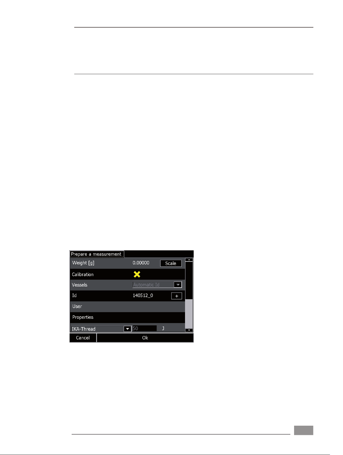
Click on the „Preparation“ button in order to
prepare for a new measurement. The following
screen appears:
With automatic decomposition vessel detection:
To make preparations for a valid measurement
you must input at least the weight of the sample.
Click on the „Weighted sample“ selection fi eld; a
virtual keyboard appears.
Working with the IKA® C 6000 global standards/isoperibol calorimeter
27
Page 28

Click on the necessary fi gures and the decimal
point, and press OK to confi rm the input.
You can also load the weight from a connected
balance or request it by clicking on the „Balance“
button. The value is then entered automatically.
All other inputs are optional.
The default is that the decomposition vessel is not
selected manually but is identifi ed when it has
been hung in the calorimeter.
Note: weight must be < 5 g.
An alphanumeric virtual keyboard appears for
the input options „Designation“, „User“, „Properties“:
Click on OK to complete the respective input.
There is a special procedure for the designation:
the default is that the designation for a sample is
constructed from the current date and a sequential number. For instance JJMMTT07 denotes the
seventh sample processed on TT.MM.JJ.
This designation is also displayed the next time. If
the last characters of the designation is numeric,
this is incremented by one.
You can stop the use of the user-specifi c designation again every time: call up the „Designation“ dialogue, delete the designation and click on
„OK“.
Highlight the „Calibration“ fi eld if you wish to
perform a calibration.
The scroll bar allows you to access additional input fi elds for inputting the external energies. If no
special application procedures must be observed
®
you can here specify use of the „IKA
ignition
thread“, „User-defi ned“ = 0, „User-defi ned“ = 0
default settings. This means that the default IKA
®
ignition thread will be used as the ignition aid and
that no further combustion aids will be used.
Simulation
In some circumstances it may be helpful to check
some calorifi c value tests or to calculate possible test results without actually performing the
combustion test. This is particularly useful when
a calibration has been carried out instead of a calorifi c value determination or vice versa. This can
be corrected by simulation using the increase in
temperature from the wrongly interpreted measurement. The decomposition vessel used can be
selected after activating the simulation.
Working with the IKA® C 6000 global standards/isoperibol calorimeter
28
Page 29
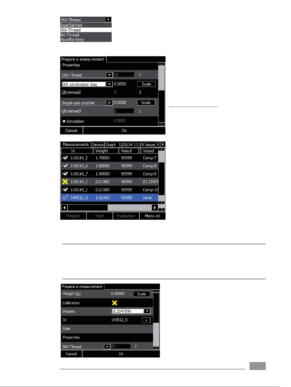
You can input values between 0 and 20,000
Joules for „External energy 2“. You can also select
specifi c types of combustion aids from the list.
In such cases you must enter the weight of this
combustion aid so that the external energy can
be calculated.
You can also load these weights directly from a
balance: The most fl exible way is to click on the
relevant „Balance“ button. The value is then loaded to the right place.
If the balance cannot receive commands, still
click on the „Balance“ button and then press the
„Transfer“ button for the balance.
Simulated measurement:
If the measurement is marked as simulation, the
increase in temperature can be set by the user.
This means that the results can be verifi ed later.
You can also load weights without clicking on the
„Balance“ button:
If the „Preparation for measurement“ screen has
not yet been opened, open it. The weights are input in the following sequence:
Weight of combustion aid 2 (if defi ned)
Weight of the sample
Weight of combustion aid 3 (if defi ned).
After all inputs have been performed in the „Preparation“ screen, click on OK; the display alongside will appear.
Note: When working without automatic decomposition vessel detection the „Start“ button
is active immediately the preparation has been
completed!
Charging the decomposition vessel
Please refer to the operating instructions for the
C 6010/ C 6012 decomposition vessels.
Calorimetric procedure without automatic decomposition vessel detection
Firstly the automatic decomposition vessel detection must be deactivated (see „New decomposition vessel“ tab, page 37).
The procedure is the same as the standard procedure with the following exceptions:
Preparation for measurement
For preparation for measurement you must select
a decomposition vessel from the list.
Working with the IKA® C 6000 global standards/isoperibol calorimeter
29
Page 30
Starting the measurement
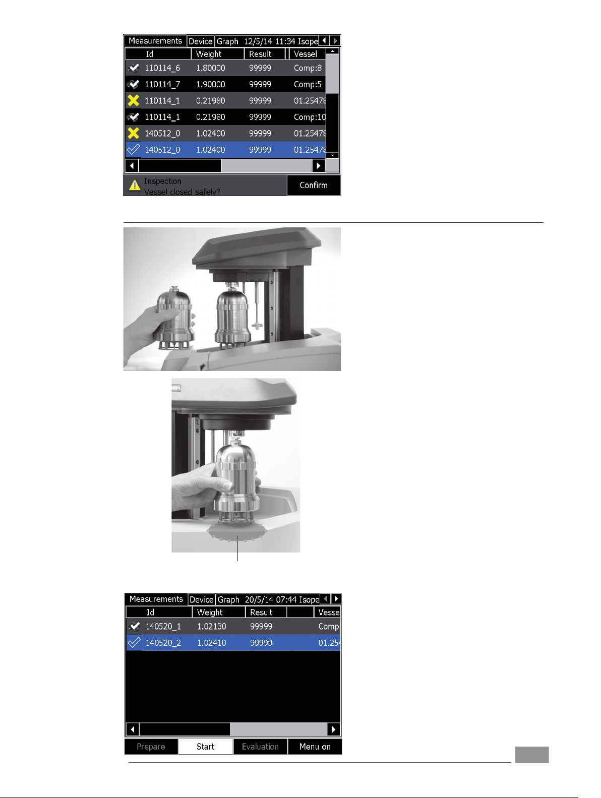
After the preparation for measurement, a message appears requiring secure closure of the decomposition vessel, despite there being no decomposition vessel hung in the calorimeter cover.
You should acknowledge the message when you
have hung the decomposition vessel in the calorimeter cover. If you accidentally press the „Start“
button before you have hung a decomposition
vessel in the calorimeter you will receive an error
message when you close the calorimeter cover.
Securely screw the decomposition vessel together and hang it in the calorimeter cover, see
operating instruction decomposition vessel C
6010/6012.
The decomposition vessel must be positioned
centrally within the fi lling head of the inner cover.
When it is correctly positioned you can feel it click
home.
Sensor area for decomposition
vessel detection
An instruction window now appears: „Check
that the decomposition vessel is securely closed“.
Click on the „Acknowledge“ button to acknowledge the instruction.
When the decomposition vessel has been hung
in the calorimeter it is identifi ed by an RFID transmitter (Rfi d: radio frequency identifi cation).
The decomposition vessel is fi tted with a transponder which is read as it passes over the sensor
area.
For this the decomposition vessel is passed over
the sensor area. A beep sounds when detection
has been successful.
You can then click on the „Start“ button.
Note: When working without automatic decomposition vessel detection the „Start“ button
is active immediately the preparation has been
completed!
Working with the IKA® C 6000 global standards/isoperibol calorimeter
30
Page 31
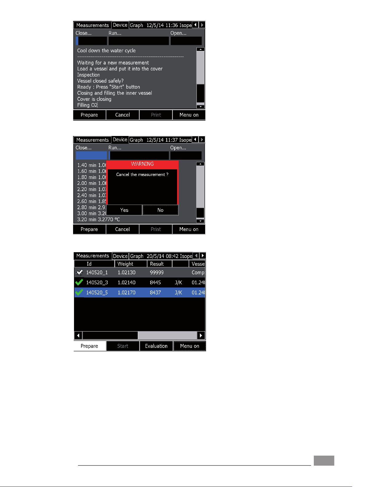
The screen switches to the „Device“ tab.
You can trace the progress of the measurement
both in this tab and also in the „Graphics“ tab. In
the area above the record, progress bars for the
individual phases of the measurement are shown.
Once the measurement has been correctly completed the calculated calorifi c value and the calculated thermal capacity also appear here.
You can cancel the measurement at any time by
clicking on „Cancel“.
After a measurement, the screen switches automatically to the „Measurements“ tab. You can
now evaluate the completed measurement. You
can also delay the evaluation until later and after
opening and cleaning the decomposition vessel
proceed to prepare and perform the next measurement as described.
Instructions for cleaning the decomposition vessels can be found in the section „Cleaning the
system“, see page 48.
Working with the IKA® C 6000 global standards/isoperibol calorimeter
31
Page 32

Evaluation
Click on auf the measurement to be evaluated.
Then click on the „Evaluation“ button. The following screen with several tabs appears. The parameters for the evaluation are distributed across
the „Calorifi c value“ and „Heat value“ tabs.
Note: The „Heat value“ tab is not shown at calibration.
Now you can input the parameters required for
the standard that was selected (here: DIN 51900
(2000)). The purpose and meaning of these parameters and the relevant calculation formulae for
the complete results can be found in the respective standard. The screens are adapted to suit the
standard that was selected.
When you have completed the inputs, switch to
the „Results form“ tab.
Here the complete data and results of the measurement are presented. You can save and print
this form.
Click on OK to fi nish the evaluation. On each occasion you can correct and extend the evaluation
for these measurements by looking them up in
the daily list or the library and selecting „Evaluation“.
You can view the trial parameters once again under the „Sample“ tab.
Working with the IKA® C 6000 global standards/isoperibol calorimeter
32
Page 33

Menu
Click the „Menu on“ button to display the menu.
Use the scroll bar to display all the menu options.
If a measurement has been prepared or selected you will see only a restricted selection of the
menu options.
„Display/hide information fi eld“: an information fi eld above the button toolbar is displayed
or hidden.
„Help“: This added the „Help“, „Servicing“ and
„Hardware details“ tabs to the screen view and
displays an information window with system information.
„Print list“: The list of measurements currently
displayed is printed (not in combination with serial printer C1.50!).
„Display/hide sample rack“: A tab with the
assignment and status of the sample rack (accessories) is displayed (see page 46).
„Delete marked measurement“: This deletes
the selected measurement from the displayed list
and also from the library. Sequential measurements and those associated with a result cannot
be deleted.
„End“: This saves the measurements taken during the day; the cover of the calorimeter is
closed and the software shut down. After this,
switch off the calorimeter and all the accessories.
Never switch the device off without previously having run „End“, otherwise data
may be lost!
Menu
33
Page 34

Library
The library screen shows all the measurements
within the memory location \FFSDISK\C6000\
tests.
In the left hand selection fi eld you can also extend an directory tree which is organised by years
and months. Within each month the right hand
window then displays the measurement organised by days.
Select the desired day and click on the „Evaluation“ button.
The list of the measurements on the selected day
is displayed. You can select a measurement then
click on the „Evaluation“ button for the measurement to evaluate it for the fi rst time or to reevaluate it, see page 37 „Evaluation“.
Menu
34
Page 35

Working Mode, Vessels and Calibrations
Alternatively you can use the actions provided by
the menu as described above.
Once you have completed the work on the measurements for the selected day, switch back to
the „Library” tab.
Once you have completed all the library work,
click on the „Back“ button.
For management of the decomposition vessels
and their associated settings, click on the „Menu“
button and then the menu item „Function, decomposition vessels and calibration“.
IKA® C 6000 global standards
®
C 6000 isoperibol
IKA
This list shows all the decomposition vessels assigned to the calorimeter. The mark on the left
in each line shows whether the decomposition
vessel is actually being used. For reasons of safety
decomposition vessels cannot be deleted.
Each decomposition vessel is uniquely identifi ed
by its RFID tag. In addition the C values for the
current function, the date of last calibration and
the number of ignitions are displayed.
Click on the „Check calibration for selected decomposition vessels and functions“ button. Three
additional tabs appear listing the calibration, a
check chart of the calibration and the calibration
statistics for the selected function and decomposition vessel.
You can select the function of the IKA® C 6000
global standards/isoperibol from a list.
Menu
35
Page 36

If you wish to change the function for subsequent
measurements, click on the „Change“ button to
start the system check for the new function.
Alternatively you can select a decomposition vessel from the updated list of decomposition vessels.
„Calibration“ tab
You can select each calibration individually and
click on the „Select“ button, or double click on
the calibration to reference this calibration in the
calculation of the C mean value (or to exclude it
if it had previously been selected). Then switch to
the „Statistics“ tab.
„Statistics“ tab
Average value, standard deviation and maximum
deviation relate to the calibration selected. Click
on the button „Load“ to load the average value
of the calibrations as the new C value.
You can also press the „Set“ button to input the
new C value manually. Press the „Confi rm“ button to load the value.
Press the „Print statistics“ button to print the
complete statistics on a connected printer. Press
the „Delete statistics“ button to delete the selection from the statistics that are referred to during
calibration.
Click on the „Save“ button, to use all the changes for the selected decomposition vessel and
the selected function. If you click on the „Undo“
button, you can completely undo these changes.
If you press „Done“ you save the inputs, exit this
menu, and revert to the overview of the measurements.
If you press „Save“ you remain in this menu and
can select other actions (such as „Check chart“).
Menu
36
Page 37

„Check chart“ tab
This displays the graphics for the selected calibration with the upper and lower warning and control limits. The scaling is adapted automatically.
LWL/UWL and LCL/UCL
The LWL and UWL (lower and upper warning limits) defi ne the area within which 95% of the
calibration measurements should lie.
The LCL and UCL (lower and upper control limits)
defi ne the area within which 99.7% of the calibration measurements must lie in order for the
device to fulfi l statistical controls.
This means that if 5% of the points (one in twenty) lie outside the warning limits or any points lie
outside the control limits, the calorimeter must
be verifi ed.
Calculation of the limits, where sigma = standard
deviation; sqrt = square root and N = number of
measurements:
UCL – mean value + 3xsigma / sqrt(N)
UWL – mean value + 2xsigma / sqrt(N)
LWL – mean value – 2xsigma / sqrt(N)
LCL – mean value – 3xsigma / sqrt(N)
If you click on „Show all“, all calibrations not just
those selected are shown in the graphics. This is
useful if there are several series of calibrations or
additional check calibrations. You can use the
check and warning lines to decide whether the C
value has shifted and therefore a reselection and
recalculation is necessary.
To exit this menu you must use the arrow keys to
switch to the „Decomposition vessels“ tab.
Exit with „Done“.
If you wish to print the check chart, press the
„Print“ button.
„New decomposition vessel“ tab
The „New decomposition vessel“ tab offers the
following options :
Use automatic decomposition vessel ID detection: automatic decomposition vessel detection
is an important precondition for safe working
with decomposition vessels. Deactivation is not
recommended but may occasionally be necessary
for repair purposes.
Menu
37
Page 38

Servicing the decomposition vessel
New decomposition vessel: click on the „New
decomposition vessel“ button to assign a new
decomposition vessel to the calorimeter. Place
the new decomposition vessel over the sensor
face. The RFID tag is detected and displayed in
the „RFID fi eld (automatic decomposition vessel
detection“. Click on the „Serial number“ fi eld and
enter the engraved serial number for the new
decomposition vessel. Finally click on the „Add“
button.
Please note that the addition of a new decomposition vessel cannot be undone.
Servicing the decomposition vessel: when you
wish to start using a decomposition vessel again
after servicing or repair, click on the „Servicing
the decomposition vessel“ button.
You will now see the name and RFID ID of the
selected decomposition vessel. Input the Service
Code for it and click on the „Renew“ button. You
will receive your service code once you have re-
gistered on the IKA® homepage.
Switch to the „Decomposition vessel“ tab and
click on the „Save“ button, then on the „Done“
button to revert to the main screen.
Evaluation
Other settings
If you require settings different from the default
settings you can create those settings in a screen
with seven tabs.
„Evaluation“ tab
Default evaluation: NAfter a measurement has
been completed, as a rule the results are extended and corrected in accordance with the applicable national or international standards.
38
Menu
Page 39

Select from the list:
The selected standard will be applied to all the
subsequent measurements.
Evaluated measurements will comply with this
standard: if a measurement has already been
evaluated, the evaluation procedure will be used
for any subsequent re-evaluation. Otherwise the
current setting for the evaluation procedure will
be used.
Measurements evaluated previously are not affected by this change.
Display unit: this sets the display units for the
calorimetric results. Select them from the list.
The selected range of units applies to the display
of energy values [J], calorifi c values [J/g] and thermal capacities [J/K].
Reference calorifi c value: Input here the calorifi c value of the substance used for calibration.
As a rule this substance is benzoic acid with a
calorifi c value certifi ed by the manufacturer.
Measurement
Other Settings
„Measurement“ tab
Double determination: If this menu item is
activated, two measurements are basically combined into a group.
The suffi x ЖRP_x is added onto the end of the
testing code. (X = 0, 1 or 2).
In the process, the fi rst two calorifi c values are
checked to ensure they fall within 120J. If the
difference between them is greater than 120J,
a warning appears that a third measurement is
required.
The third measurement must then fall within
120J of one of the fi rst two measurements.
If the fi rst two measurements fall within 120J of
each other, the next measurement creates a new
group.
39
Page 40

Load parameters: Some parameters from the
previous measurement (Name, User, Properties,
ignition and combustion aid) can be retained
when preparing for a new measurement.
No venting: The venting of the decomposition
vessel after measurement is skipped in order to
facilitate determination of the products of combustion.
Restart: If a measurement is cancelled prior to
ignition, after rectifying the cause of the cancellation you can restart the measurement without
having to prepare a new measurement.
O2 purging: Two fi lling and emptying cycles are
performed before fi lling with oxygen, in order
that purging with oxygen will reduce the proportion of nitrogen remaining in the decomposition
vessel to an insignifi cant residue.
Ignition aids
Water supply line port: The calorimeter is operated using a water supply; the internal temperature regulation parameters must be adjusted
accordingly.
„Ignition aids“ tab
You can use an ignition aid to ensure that samples are correctly and reliably ignited. The external
energy contributed by the aid must be included
when calculating the calorifi c value.
Add new ignition aid
Ignition aids:
Select an ignition aid from the list:
Note: These predefi ned ignition aids cannot be
changed.
An energy value is defi ned for each ignition aid;
this value is included automatically in the calculation of the calorifi c values. If you select „userdefi ned“ this energy value can also be changed at
the preparation of each individual measurement.
The default setting is „IKA ignition thread“
You can modify the list or add new ignition aids
to it.. Select an ignition aid and click on the „Edit“
button to activate the input fi elds for this.
You must change the name and the energy values. Click on „Load“ to modify the selected ignition aid. Click on „Add“ to add a new ignition aid
to the list with the data that were input. Click on
„Cancel“ to make no changes.
Other Settings
40
Page 41

Combustion aid
„Combustion aids“ tab
There are two different combustion aids available
for use in order to achieve correct combustion
of samples. The external energies contributed by
the aids are input or calculated at preparation of
the sample and are included automatically in the
calculation of the calorifi c values.
A list is provided for the most commonly used
combustion aids, showing their calorifi c values.
If one of these combustion aids is used during
preparation of the sample you need only input its
weight or load it from the balance.
You can modify the list or add new combustion
aids to it.
Select a combustion aid from the list and click on
the „Edit“ button to activate the input fi elds for
it . You can the change the name and the calorifi c value. Click on „Load“ to modify the selected
combustion aid. Click on „Add“ to add a new
combustion aid to the list with the data that were
input. Click on „Cancel“ to make no changes.
Balance
„Balance“ tab
You can select the balance from a list.
The default values for the serial interface are set
for each selected type of balance. If necessary
you can change the values for Baud rate, parity,
data bits and stop bits.
Click on „OK“ to use all the changed settings for
the subsequent calorimetric procedures.
Click on „Cancel“ to leave all the settings unchanged.
Other Settings
41
Page 42
Printer
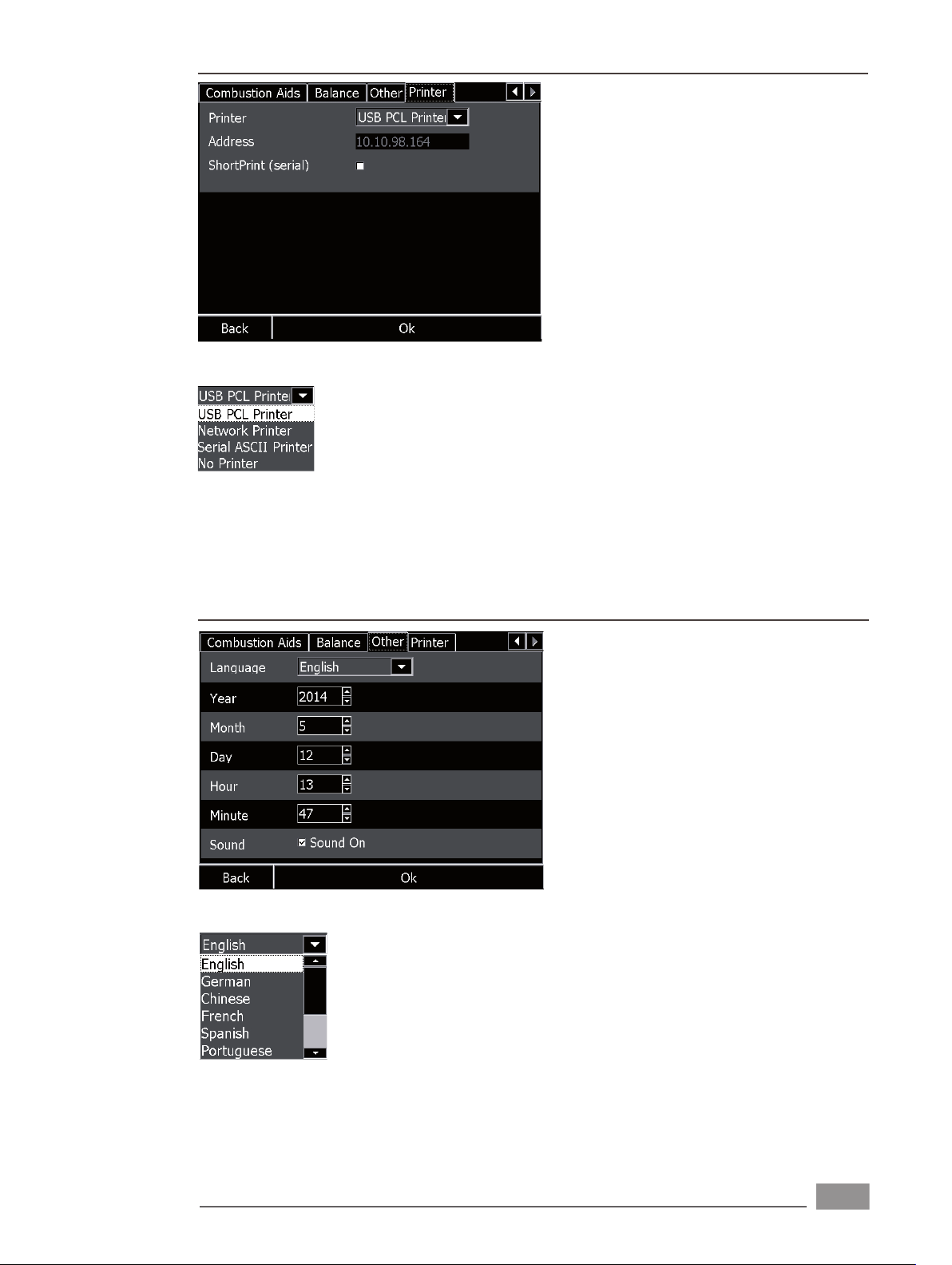
„Printer“ tab
Select a suitable printer from the list.
USB PCL printer
You can connect many type of USB printers which
the use the PCL printer language to the C 6000.
We recommend the HP Business Inkjet 1200 or
its successor models.
Network printer
When you have selected a network printer you
must then input the network address of the printer. In addition the C 6000 must be connected to
the company‘s network.
Serial printer
A serial printer can be connected to PC port of
the C 6000. This printer allows printing of the sequential record of the measurements. No other
printing operations can be performed with this
printer. We recommend the IKA® C 1.50 printer
with the serial settings 9600-8-N-1.
Other
„Other“ tab
Language:
You can select the language from a list.
The default language is English. The next start of
the device makes the change of language effective.
Year, month, day, hour, minute:
These settings become effective when you click
on the „OK“ button. The input fi eld for the hour
uses the 24-hour format.
Other Settings
42
Page 43
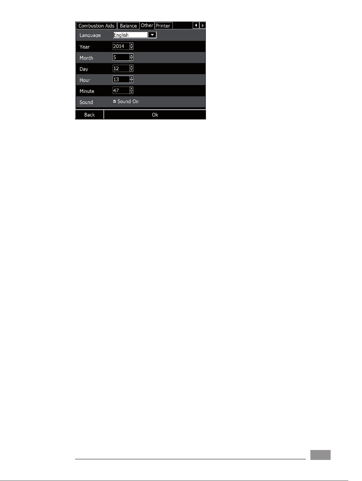
Speaker:
Activation of the speakers.
Other Settings
43
Page 44

Help ans servicing system
Help
You can activate and display the „Help“ tab at
any time to obtain detailed information on the
current status and available actions for the calorimeter. Click on either the „Help“ button in the
information fi eld or on the „Help“ menu item and
switch to the „Help“ tab. The „Hardware details“
and „Servicing“ tabs are also displayed as well as
the „Help“ tab.
The left hand selection fi eld displays an extendable list of all statuses, views and fault options. The
current status or fault is selected automatically
and the explanation for it shown in the upper
right selection fi eld. If this information is insuffi cient you can navigate the left hand selection fi eld
further to obtain more information.
Click on the desired topic then click on the right
hand fi eld with the arrow symbol.
Here you can obtain detailed information on the
topic. Click on the left hand fi eld with the arrow
symbol, to revert to the overview of topics and if
necessary select a different topic.
Help and servicing system
Maintenance
Depending on the current status and the information obtained you can perform various actions
using the buttons in the „Servicing“ tab.
Filling with O2:
The decomposition vessel can be fi lled with oxygen manually.
Filling with water:
The inner vessel can be fi lled manually.
The safety functions are deactivated for
fi lling.
Venting:
The decomposition vessel can be vented manually. In addition this menu item allows the gasket
on the fi lling head to be changed.
44
Page 45
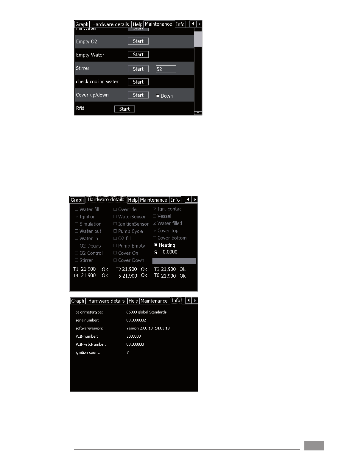
Empty:
The inner vessel can be emptied manually.
Stirrer:
Here the operation of the stirrer can be tested.
After the start the stirrer speed is displayed.
Cooling water:
After the start the current cooling water temperature at the entry into the calorimeter is displayed.
Cover up/down:
The cover can be opened and closed manually.
RFID:
After the start the decomposition vessel detection is activated and the RFID code of the decomposition vessel can be read.
Click on „Stop“ to stop the function test.
Hardware details
In addition you can switch to the „Hardware details“ tab.
This tab shows you all the information about the
digital inputs and outputs, the temperature values on all the measurement channels, various
counters and statuses of accessories. You cannot make any changes here. The information
displayed can be forwarded to Service Engineers
who have access to various settings.
Info
Here you can call up important information for
servicing purposes:
- Serial number of the calorimeter
- Software version
- PCB* number
- PCB* works number
- Number of ignitions
Help and servicing system
*PCB = printed circuit board
45
Page 46
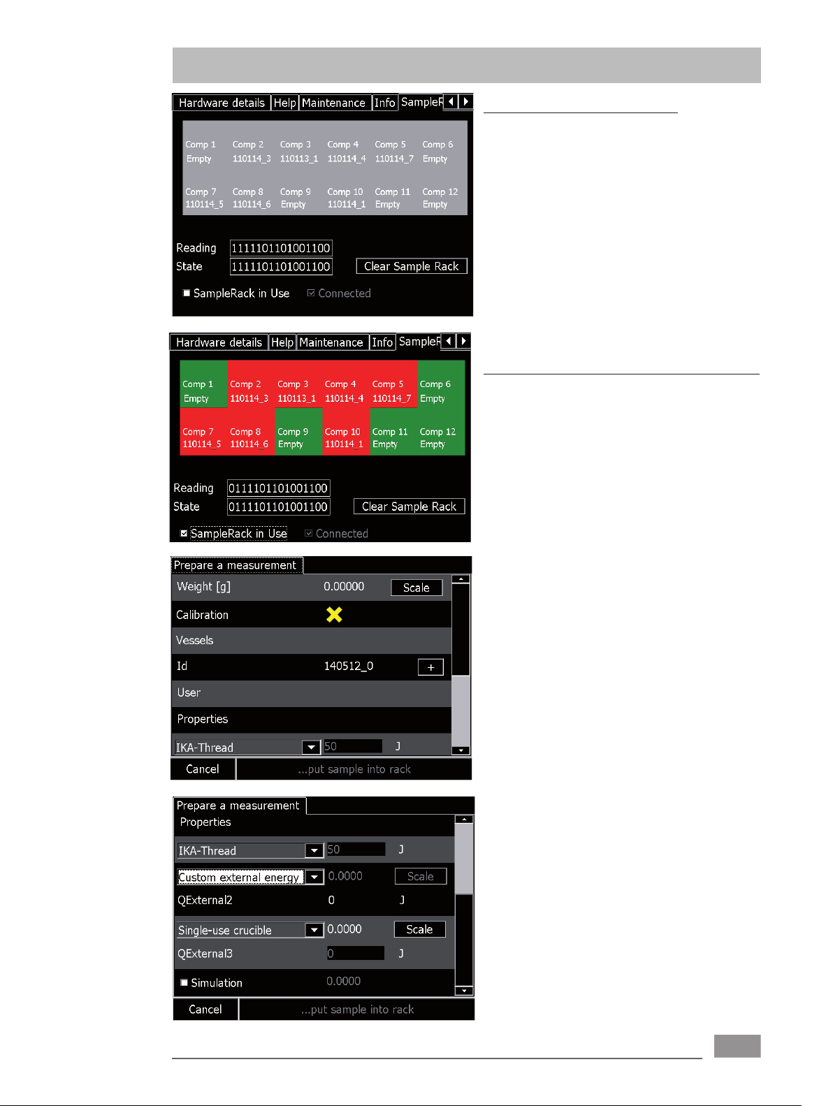
Displaying/hiding the sample rack
Working with the sample rack
To work with the sample rack you must fi rst check
that it is connected to the calorimeter.
Open the “Sample rack” screen from the main
menu.
After this you can use the „Use sample rack“
menu item to activate/ deactivate its use.
A schematic representation of the assignment
of the rack is displayed in the upper area of the
menu.
> Green = free
> Red = occupied
> Grey = rack not connected/recognised
-
Working with the sample rack and balance
If a balance is connected to the IKA® C 6000
global standards/isoperibol calorimeter, the
weighted sample can be sent directly from the
balance to the IKA® C 6000 global standards/
isoperibol calorimeter.
There are two possibilities:
a) Press the “Print” button on the balance:
Pressing the “Print” button automatically opens
the preparation dialogue box and the
weighted sample value is entered automatically.
If External Energy 2 is not set to user-defi ned, the
fi rst weighted sample value is entered into the
weighted value fi eld for External Energy 2 and the
energy is calculated automatically.
If External Energy 2 is set to user-defi ned, the
weighted sample value is entered directly into the
test weighted value fi eld and the second weighted sample value is entered into the External Energy 3 fi eld (as long as it is not set to user-defi ned).
The energy values are calculated automatically
based on the weighted sample and
reference calorifi c value entered.
The sequence of fi gures transferred is as follows:
1. Weight External Energy 2 (if not user-defi ned)
2. Test weighted sample
3. Weight External Energy 3 (if not user-defi ned)
Displaying/hiding the sample rack
46
Page 47
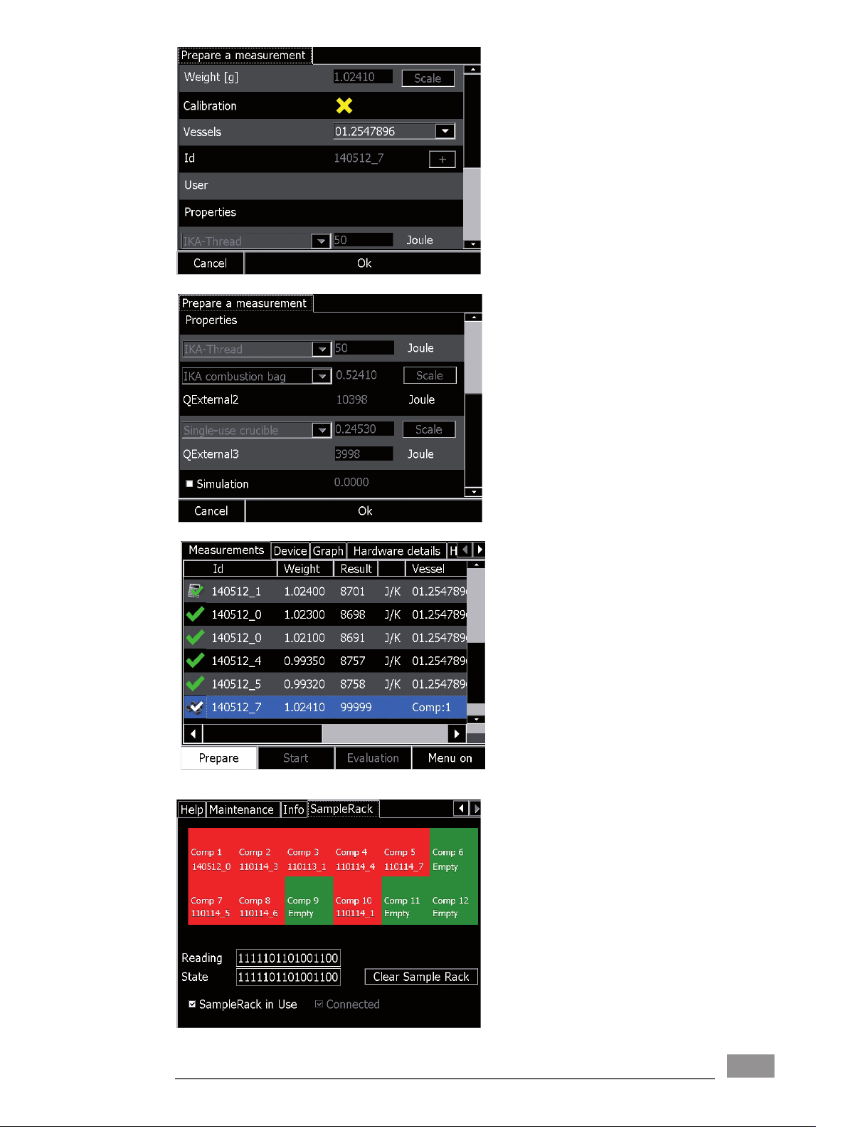
CAUTION: Before each weighing and transfer of
values from the balance, the “TARE”
key needs to be pressed.
If the crucible is placed in the sample rack, the
input fi eld is closed automatically and the prepared measurement appears in the measurement
window.
If the crucible is now removed from the sample
rack, the input fi eld opens once more and combustion aids can be added (if this has not already
been done).
If entries have already been made the input fi eld
is deactivated.
b) Opening the preparation dialogue box on the
calorimeter by pressing the “Preparation” button.
With the preparation dialogue box open, the “Balance” key can be used to assign the weighted
sample values to the appropriate input fi elds.
The balance value is always entered into the corresponding fi eld.
In order to close the dialogue box, the crucible
must always be placed in an empty compartment
in the sample rack.
Now you can prepare further measurements and
fi ll up the rack.
The „Sample rack“ tab allows you to check the
current assignment for the rack:
If you wish to start a measurement that has been
prepared in the sample rack, just take out the respective crucible. The dialogue „Preparation for
measurement“ opens with the values previously entered (weighted sample, name,...) and you
can check this data and if necessary select a decomposition vessel. After the dialogue has been
closed with „OK“, the system continues with the
standard calorimetric procedure.
Displaying/hiding the sample rack
47
Page 48

You can prepare a maximum of 12 measurements
in the sample rack, and process them in any order. The assignment remains saved even when the
IKA® C 6000 global standards/isoperibol calori-
meter is switched off. If a crucible unsuitable for
the specifi ed procedure is set or taken out, a message appears and the action must be reversed.
Caution: if you change the assignment of the
sample rack whilst the IKA® C 6000 global stan-
dards/isoperibol calorimeter is switched off you
must discard all samples!
Cleaning
Cleaning the system
In serious cases (such as accidental removal of
crucibles whilst the calorimeter is switched off),
click on the „Reset sample rack“ button. This
deactivates the sample rack. Remove all the crucibles still standing in the sample rack. The measurements for them still remain displayed in the list
but can no longer be used. After this you can once
again click on „Use sample rack“.
®
When the IKA
ribol calorimeter is restarted the last rack assign-
ment is saved and can continue to be used.
C 6000 global standards/isope-
After the result has been recorded, you can take
out the decomposition vessel, open it and clean it.
If you suspect that the combustion sample, the
combustion gases produced or the combustion
residue could be harmful to health, wear personal protective equipment (e.g. protective gloves,
breathing masks) when handling these materials.
Harmful or polluting combustion residue must be
disposed of as hazardous waste. Express reference
is made to the applicable regulations.
In order to obtain accurate measurements it is
essential that the decomposition vessel is clean
and dry. Impurities alter the heat capacity of the
decomposition vessel and thus cause inaccurate
measuring results. It is important to thoroughly
clean the inner walls of the vessel, the internal fi ttings (brackets, electrodes etc.) and the combus-
Servicing and cleaning the fi lter
Servicing
Check the fi lter every week or according to experience. Over time the fi lter becomes clogged with
sludge thereby causing a reduction in the cooling
water fl ow rate.
tion crucible (inside and out!) after each combustion test.
In most cases all that is necessary is to remove
condensate from the inner walls of the vessel and
the internal fi ttings. It is suffi cient to thoroughly
wipe the parts with an absorbent, non-fi brous
cloth.
If the decomposition vessel cannot be cleaned in
the above way (e.g. due to baking, pitting, corrosion etc.), please contact Technical Service.
The combustion residue in the crucible, e.g. soot
or ashes, should also be wiped away with an absorbent non-fi brous cloth.
Do not use distilled or demineralized water
(increased risk of corrosion)! Fill the cooler
according to the cooler operating instructions. is
recommended in drinking tap water quality. Mix
in (max. 1 ml for 4-5 l of water) of the supplied
water additive. Thus, the durability of the water is
improved.
Displaying/hiding the sample rack
48
Page 49

Cleaning
• Switch the device off.
• Switch the cooling water supply off (switch off
the condenser, clock the water shut-off valve).
• Disconnect the hoses from the device.
• Have an absorbent cloth ready to hand.
• Turn the fi lter casing anticlockwise, some water
will escape. wipe up the water with the cloth.
• Pull out the sieve.
Troubleshooting
• Use a suitable brush to clean the sieve inside
and out.
• Place the sieve back in the fi lter.
• Screw the fi lter casing on again fi nger-tight.
• Reconnect the hoses to the device (see also the
section „Commissioning“).
• Switch the cooling water supply on again.
• Switch the device on again.
In the event of a fault you will see an error message in the information fi eld. This appears automatically.
You can click on the „Help“ button to obtain detailed information on the fault.
If the fault is non-critical you can click on the
„Acknowledge“ button. After that you can rectify
the cause of the fault and repeat the action that
led to the fault.
If the fault occurred during a measurement the
error message is displayed initially without the
„Acknowledge“ button.
After this the calorimeter is opened automatically.
Once the calorimeter is open and has been vented and emptied the error message is displayed
once again, this time with the „Acknowledge“
button.
Cleaning
49
Page 50

In certain exceptional cases the fault may prevent the calorimeter being available for measurements.
In such cases the calorimeter initiates a system
test directly the „Acknowledge“ button is clicked.
After you have taken the actions described in the
Help or in the operating instructions, click on the
„Restart“ button to start the system test. On successful completion of the system test the IKA® C
6000 global standards/isoperibol is again available for measurements.
Troubleshooting
50
Page 51

Fault rectifi cation
Display Description
No heating pulse in the inner
circuit.
The function cannot be performed
Drift criterion not achieved This error message is generated
No increase in temperature
within the inner water circuit.
No increase in temperature
within the outer water circuit.
The selected function cannot be
used because the temperature
of the cooling water has not
reached the required values.
during a measurement of the
„Equalise“ or „Main Test“ status
if the drift conditions for the current function of the C 6000 cannot be met.
What should be done?
What happens next?
Acknowledge the alarm.
Check the cooling water fl ow
Check the circulating pump.
Click on „Restart“ to repeat the
system test.
Click on „Next“ to skip the system test.
Acknowledge the alarm.
Check the cooling water fl ow
Check the condenser and the
water infl ow.
Click on „Restart“ to repeat the
system test.
Click on „Next“ to skip the system test.
Acknowledge the alarm.
Check the cooling water fl ow
Check the condenser and the
water infl ow.
Check the circulating pump.
Click on „Restart“ to repeat the
system test.
Click on „Next“ to skip the system test.
Acknowledge the error message
to revert to the „Wait“ message.
Switch to the „Servicing“ tab
and press the „Stirrer“ button to
check that the stirrer is working.
Perform a calibration of the C
6000.
Establish the specifi ed ambient
conditions.
Troubleshooting
51
Page 52

Display Description
No increase in temperature after
ignition.
Measurement was cancelled by
the user.
Cover not closed, or no decomposition vessel is hung in the
calorimeter cover.
Water circuit unstable The stability criterion for the re-
This error message is generated,
if the increase in temperature
has not achieved the specifi ed
value within the fi rst minute after ignition.
This error message is triggered in
the Close, Run, Open conditions
if the user the presses the „Cancel“ button.
a. The cover did not reach the
lower cover contact.
b. The ignition contact did not
close.
gulation of the water circuits to
the working temperature was
not achieved within the specifi ed
period of time.
What should be done?
What happens next?
Acknowledge the error message
to revert to the „Wait“ message.
The sample is combusted.
The weighted sample of the
sample may be insuffi cient.
The calorifi c value of the sample
is too small, use a combustion
aid.
The oxygen pressure is insuffi cient
The stirrer is not working.
The sample has not been combusted, despite the provision of
an ignition thread:
The ignition thread was blown
away from the sample
The oxygen pressure is insuffi cient
Sample and ignition thread were
not combusted:
Check the ignition system.
Acknowledge the error message
to revert to the „Wait“ message.
Acknowledge the error message
to revert to the „Wait“ message.
a. Switch to the „Servicing“ tab.
Press the „Close“ button.
b. No decomposition vessel
hung in the cover
Ignition circuit open circuit.
Acknowledge the error message
to revert to the „Wait“ message.
Check the water circuit
Check the heating
We recommend performing a
system test to localise more precisely the cause of the problem.
Troubleshooting
52
Page 53

Display Description
What should be done?
What happens next?
Water not fi lling OK. The system could not completely
fi ll the inner vessel with
water completely within the specifi ed period of time.
Acknowledge the error message
to revert to the „Wait“ message.
Water level in the condenser too
low.
Water fl ow rate insuffi cient.
Defect at the water sensor. The water sensor shows comple-
tely full within a very short time.
Acknowledge the error message
to revert to the „Wait“ message.
Check whether a drip is handing
from the water sensor.
Blow out the recess around the
water sensor.
Rfi d ID of the new decomposition vessel not accepted.
This error message is triggered
by the dialogue „New decomposition vessel“ if you attempt
to register a new decomposition
vessel at the C6000 using an Rfi d
Acknowledge the error message
to continue the dialogue.
Use a different Rfi d ID for this decomposition vessel.
Contact IKA
ID that has already been used.
xxxxxxxxxxx : This Rfi d ID cannot
be assigned
The Rfi d value detected does not
match any of the decomposition
vessel registered at the C 6000.
Acknowledge the error message
to revert to the „Prepared“ message.
Check whether the vessels have
been mixed up.
Check whether a misleading Rfi d
is stated anywhere.
Register this decomposition vessel at the C 6000.
Converter alarm High-precision temperature
measurement is one of the core
functionalities of the calorimeter.
Any error message regarding the
temperature recording brings
the current measurement to an
end and demands a system test.
Further work using the calorimeter can be performed only once
the system test has been completed successfully.
Acknowledge the error message
in order to switch to the „System
Check“ status.
Press the „Restart“ button“.
The temperature converter is reset and the system test starts.
On successful completion the
status switches to „Wait“
If the system test was unsuccessful, switch the C 6000 off and on
again.
If the system test is unsuccessful
again, please contact IKA
tomer Service.
®
Customer Service.
®
Cus-
Troubleshooting
53
Page 54

Display Description
Controller alarm The reliable regulation of the
outer vessel is a major precondition for good quality measured
values. Any error message from
the controller brings the current
measurement to an end and demands a system test.
Further work using the calorimeter can be performed only once
the system test has been completed successfully.
What should be done?
What happens next?
Acknowledge the error message
in order to switch to the „System
Check“ status.
Press the „Restart“ button“.
The temperature converter and
the controller are reset and the
system test starts.
On successful completion the
status switches to „Wait“
If the system test was unsuccessful, switch the C 6000 off and on
again.
If the system test is unsuccessful
again, please contact IKA® Customer Service.
Troubleshooting
54
Page 55

Checks
Various major parts of the calorimeter are monitored. Information about when the servicing
intervals defi ned by the manufacturer for these
parts fall due is shown in the information fi eld,
with the invitation to perform servicing actions.
You must then confi rm performance of the servicing actions.
Click on „Acknowledge“ to acknowledge performance of the servicing actions.. The acknowledgement is saved and can be checked by the
Service Engineers.
If you click on the „Help“ button you will be given
instructions on exactly what to do.
This monitoring is the precondition for a high
degree of safety and we ask you to follow the
stated instructions precisely.
At the latest after 500 measurements, check the
O-ring, fi lter etc..
Troubleshooting
55
Page 56

Accessories and consumables
Accessories
C 6010 Decomposition vessel
C 6012 Decomposition vessel
C 5010.5 Crucible holder, large
C 5010.8 Crucible holder, small
C 21 Pelleting press
C 5020 Sample rack
C 29 Pressure reducer, oxygen
C 6030 Gas washing station
C 27 Calorimeter instrument set
C 5041.10 Connecting cable 9-pin / 3m
C 6040 Calwin
C 1.50 Dot-matrix printer
C 60.1020 Organiser
Consumables
C 723 Benzoic acid blister pack, 50 pieces
C 723 Benzoic acid big pack
C 43 Benzoic acid NIST 39i
C 710.4 Cotton wool threads cut to length
C 710.8 Cotton wool threads cut to length, thick
C 16 Parafi lm 1000x50
C 17 Paraffi n liquid 30 ml
C 15 Paraffi n strips 600 pieces/package
C 9 Gelatine capsules (100 pieces)
C 10 Acetobutyrate capsules (100 pieces)
C 12 A Combustion bag, 70 x 40 mm (100 pieces)
C 12 Combustion bag, 40 x 35 mm (100 pieces)
AOD 1.11 Control standard for sulphur and chlorine
AOD 1.12 Control standard for fl uorine and bromine
C 1.103 Ignition wire
C 1.123 Ignition wire, platinum
C 14 Combustible crucible (100 pieces)
C 5 VA VA combustion crucible set (25 pieces)
C 710.2 VA VA Combustion crucible large (25 pieces)
C 4 Quartz dish
C 6 Quartz dish large
C 6000.10 Spare parts kit 1000
C 6000.12 Spare parts kit 1000
For further accessories see www.ika.com.
Accessories and consumables
56
Page 57

Technical data
IKA® C 6000 global standards
Measuring range max. ..................................................................................... J ................................................ 40000
Measuring mode adiabatic 22 °C .............................................................................................................................yes
Measuring mode dynamic 22 °C ...............................................................................................................................yes
Measuring mode isoperibolic 22 °C ..........................................................................................................................yes
Measuring mode adiabatic 25 °C .............................................................................................................................yes
Measuring mode dynamic 25 °C ..............................................................................................................................yes
Measuring mode isoperibolic 25 °C ..........................................................................................................................yes
Measuring mode adiabatic 30 °C .............................................................................................................................yes
Measuring mode dynamic 30 °C ..............................................................................................................................yes
Measuring mode isoperibolic 30 °C ..........................................................................................................................yes
Measuring/hour adiabatic ........................................................................................................................................... 5
Measuring/hour dynamic ............................................................................................................................................ 7
Measuring/hour isoperibolic ........................................................................................................................................ 4
Reproducibility adiabatic (1g benzoic acid NBS39i) ....................................... %RSD ............................................... 0.05
Reproducibility dynamic (1g benzoic acid NBS39i) ........................................ %RSD ............................................... 0.15
Reproducibility isoperibolic (1g benzoic acid NBS39i) .................................... %RSD ............................................... 0.05
Touchscreen .............................................................................................................................................................yes
Working temperature min. .............................................................................. °C .................................................... 22
Working temperature max. .............................................................................°C .................................................... 30
Temperature measurement resolution ..............................................................K .............................................. 0.0001
Cooling medium temperature min. .................................................................. °C .................................................... 12
Cooling medium temperature max. ................................................................. °C .................................................... 27
Cooling medium permissible operating pressure ............................................. bar ................................................... 1.5
Cooling medium .......................................................................................................................water quality tap water
Type of cooling ....................................................................................................................................continuous fl ow
Flow rate min. .................................................................................................l/h .................................................... 60
Flow rate max. ................................................................................................ l/h .................................................... 70
Recommended fl ow rate at 18 °C ...................................................................l/h .................................................... 60
Oxygen operating pressure max ..................................................................... bar .................................................... 40
Interface to scales ...................................................................................................................................... RS232 serial
Interface to printer ................................................................................................................. USB, RS232 and network
Interface to PC ....................................................................................................................................................RS232
Interface to sample rack .................................................................................... .....................................................yes
Interface to ext. keyboard ........................................................................................................................................yes
Oxygen fi lling .................................................................................................... .....................................................yes
Degassing ................................................................................................................................................................yes
Decomposition vessel detection ...............................................................................................................................yes
Decomposition vessel C 6010 ..................................................................................................................................yes
Decomposition vessel C 6012 ..................................................................................................................................yes
Evaluation to DIN 51900 ..........................................................................................................................................yes
Evaluation to DIN EN ISO 1716 ................................................................................................................................yes
Evaluation to DIN EN ISO 9831 ................................................................................................................................yes
Evaluation to DIN EN 15170 .....................................................................................................................................yes
Evaluation to DIN CEN TS 14918 ..............................................................................................................................yes
Evaluation to ASTM D240 ........................................................................................................................................yes
Evaluation to ASTM D4809 ............................................................................... .....................................................yes
Technical data
57
Page 58

Evaluation to ASTM D5865 ......................................................................................................................................yes
Evaluation to ASTM E711 .................................................................................. .....................................................yes
Evaluation to ISO 1928 ............................................................................................................................................yes
Evaluation to BG T213 .............................................................................................................................................yes
Width ............................................................................................................mm ................................................ 500
Depth ............................................................................................................mm ................................................. 450
Height ...........................................................................................................mm ................................................. 425
Weight ...........................................................................................................kg .................................................... 29
Permissible ambient temperature min. .............................................................°C .................................................... 20
Permissible ambient temperature max. ............................................................°C .................................................... 25
Perm. humidity rel. .......................................................................................... % ..................................................... 80
Protection to DIN EN 60529 ..................................................................................................................................IP 20
RS 232 interface ......................................................................................................................................................yes
USB interface ...........................................................................................................................................................yes
Rated voltage ...................................................................................................V .......................................... 220 - 240
Rated voltage ...................................................................................................V .......................................... 100 - 120
Frequence .......................................................................................................Hz ............................................... 50/60
Power consumption ........................................................................................ W ................................................. 2000
Fuses (220-240 V) .......................................................................................................................................... 2x 6.25 A
Fuses (100-120 V) .......................................................................................................................................... 2x 12.5 A
Perm. on time ...............................................................................................................................continuous operation
Protection class ...........................................................................................................................................................III
Overvoltage category .................................................................................................................................................. 2
Contamination level .....................................................................................................................................................II
Operation at a terrestrial altitude ........................................................................................... max. 2000 above sea level
Subject to technical changes!
Technical data
58
Page 59

IKA® C 6000 isoperibol
Measuring range max. ..................................................................................... J ................................................ 40000
Measuring mode dynamic 22 °C ...............................................................................................................................yes
Measuring mode isoperibolic 22 °C ..........................................................................................................................yes
Measuring mode dynamic 25 °C ..............................................................................................................................yes
Measuring mode isoperibolic 25 °C ..........................................................................................................................yes
Measuring mode dynamic 30 °C ..............................................................................................................................yes
Measuring mode isoperibolic 30 °C ..........................................................................................................................yes
Measuring time* dynamic approx. .................................................................. min ..................................................... 8
Measuring time* isoperibolic approx. .............................................................min ................................................... 16
Reproducibility dynamic (1g benzoic acid NBS39i) ........................................ %RSD ................................................. 0.1
Reproducibility isoperibolic (1g benzoic acid NBS39i) .................................... %RSD ............................................... 0.05
Touchscreen .............................................................................................................................................................yes
Working temperature min. .............................................................................. °C .................................................... 22
Working temperature max. .............................................................................°C .................................................... 30
Temperature measurement resolution ..............................................................K .............................................. 0.0001
Cooling medium temperature min. .................................................................. °C .................................................... 12
Cooling medium temperature max. ................................................................. °C .................................................... 27
Cooling medium permissible operating pressure ............................................. bar ................................................... 1.5
Cooling medium .......................................................................................................................water quality tap water
Type of cooling ....................................................................................................................................continuous fl ow
Flow rate min. .................................................................................................l/h .................................................... 60
Flow rate max. ................................................................................................ l/h .................................................... 70
Recommended fl ow rate at 18 °C ...................................................................l/h .................................................... 60
Oxygen operating pressure max ..................................................................... bar .................................................... 40
Interface to scales ...............................................................................................................................................RS232
Interface to printer ................................................................................................................. USB, RS232 and network
Interface to PC ....................................................................................................................................................RS232
Interface to sample rack .................................................................................... .....................................................yes
Interface to ext. keyboard ........................................................................................................................................yes
Oxygen fi lling .................................................................................................... .....................................................yes
Degassing ................................................................................................................................................................yes
Decomposition vessel detection ...............................................................................................................................yes
Decomposition vessel C 6010 ..................................................................................................................................yes
Decomposition vessel C 6012 ..................................................................................................................................yes
Evaluation to DIN EN ISO 1716 ................................................................................................................................yes
Evaluation to DIN EN ISO 9831 ................................................................................................................................yes
Evaluation toh DIN EN 15170 ...................................................................................................................................yes
Evaluation to DIN CEN TS 14918 ..............................................................................................................................yes
Evaluation to ASTM D240 ........................................................................................................................................yes
Evaluation to ASTM D4809 ............................................................................... .....................................................yes
Evaluation to ASTM D1989 ......................................................................................................................................yes
Technical data
59
Page 60

Evaluation to ASTM D5865 ......................................................................................................................................yes
Evaluation to ASTM E711 .................................................................................. .....................................................yes
Evaluation to ISO 1928 ............................................................................................................................................yes
Evaluation to BG T213 .............................................................................................................................................yes
Width ............................................................................................................mm ................................................ 500
Depth ............................................................................................................mm ................................................. 450
Height ...........................................................................................................mm ................................................. 425
Weight ...........................................................................................................kg .................................................... 29
Permissible ambient temperature min. .............................................................°C .................................................... 20
Permissible ambient temperature max. ............................................................°C .................................................... 25
Perm. humidity rel. .......................................................................................... % ..................................................... 80
Protection to DIN EN 60529 ..................................................................................................................................IP 20
RS 232 interface ......................................................................................................................................................yes
USB interface ...........................................................................................................................................................yes
Rated voltage ...................................................................................................V .......................................... 220 - 240
Rated voltage ...................................................................................................V .......................................... 100 - 120
Frequence .......................................................................................................Hz ............................................... 50/60
Power consumption ........................................................................................ W ................................................. 2000
Fuses (220-240 V) .......................................................................................................................................... 2x 6.25 A
Fuses (100-120 V) .......................................................................................................................................... 2x 12.5 A
Perm. on time ...............................................................................................................................continuous operation
Protection class ...........................................................................................................................................................III
Overvoltage category .................................................................................................................................................. 2
Contamination level .....................................................................................................................................................II
Operation at a terrestrial altitude ........................................................................................... max. 2000 above sea level
Subject to technical changes!
Technical data
60
Page 61

Page 62

Page 63

Page 64

IKA® - Werke
GmbH & Co.KG
Janke & Kunkel-Str. 10
D-79219 Staufen
Tel. +49 7633 831-0
Fax +49 7633 831-98
sales@ika.de
www.ika.com
*4345900A*
00/0000/0
 Loading...