

Page 1
IKA® Calorimeter C 1
20000004724
Operating instructions EN
C 1_042016
Page 2
2
EN
We declare under our sole responsibility that this product is in compliance with the regulations
2014/68/EC
(article 3, (3)),
2011/65/EU,
2014/30/EU
and 2014/35/EU
and conforms to the standards or standardized documents: EN 61010-1, EN 61326-1, EN 60529 and EN ISO
12100.
Declaration of Conformity
Explication of warning symbols
User notes
The warranty does not cover worn out parts, nor does it apply
to faults resulting from improper use, insucient care or
maintenance not carried out in accordance with the instructions
in this operating manual.
Please read these operating instructions carefully.
IKA® only
consider themselves to be responsible for the safety, reliability
and performance of the appliance when
• the appliance has been operated in accordance with the
operating instructions,
• only persons authorised by the manufacturer interfere with
the
appliance,
• only original parts and original accessories are used for repairs.
The calorimeter system may be opened only by an authorised
Service Agent or Customer Service Centre.
If service is required, we recommend that you contact our
customer service department. Furthermore, we refer you to the
applicable safety conditions and accident requirements.
IKA® is not responsible for damages or costs resulting from
accident, improper use of the device or impermissible modifications,
repairs or renovations.
Read the operation instructions completely before
starting up and follow the safety instructions.
Keep the operation instructions in a place where they can be
accessed by everyone.
Ensure that only trained staff work with the appliance.
Follow the safety instructions, guidelines, occupational health and
safety and accident prevention regulations.
In this chapter you can find out how to work through these
Operating Instructions most effectively to be able to work reliably
with the calorimeter system.
The instructions in the section “Safety instructions“ must
be complied with.
The chapters are designed for you to work through them in order.
The section “Transport, storage“ is relevant for system reliability
and for ensuring high measuring accuracy.
The calorimeter system is ready to perform measurements once
you have completed the procedures in the section “Setting up
and commissioning“: - “Preparing a measurement“ and “Starting
a measurement“.
Numbers 1, 2, 3 etc. indicate operating instructions in the
following sections. These must always be carried out in the
specified sequence.
Warranty and liability
In accordance with
IKA® warranty conditions, the warranty period
is 12 months. For claims under the warranty please contact your
local dealer. You may also send the machine direct to our factory,
enclosing the delivery invoice and giving reasons for the claim.
You will be liable for freight costs.
DANGER
CAUTION
WARNING
NOTICE
Indicates an imminently hazardous situation, which, if not avoided, will result in death, serious injury.
Indicates a potentially hazardous situation, which, if not avoided, can result in death, serious injury.
Indicates a potentially hazardous situation, which, if not avoided, can result in injury.
Indicates practices which, if not avoided, can result in equipment damage.
Reference to exposure to a hot surface!
DANGER
Page 3

3
Page
Declaration of Conformity 02
Explication of warning symbols 02
User notes 02
Contents 03
Safety instructions 04
Correct use 05
System properties 05
Transportation, Storage 06
Transport and Storage conditions 06
Unpacking 06
Scope of delivery 06
Description of the system components 06
Hoses 07
Commissioning 07
Place of installation 07
Cooler connection 08
Venting hose connection 08
Drain hose connection 08
Oxygen supply connection 08
Power supply unit connection 09
Connection of peripherals 09
Handling the unit 09
Control unit with display 10
Dialog box 11
System start 12
Switching on the system (in the open state) 12
Selection of language 12
Pressure test 13
Oxygen pressure 13
System check 13
Heating detected 14
Factory settings 14
Calorimetric measurements 14
Determination of gross calorific value 14
Corrections 15
Notes on the sample 15
Complete combustion 16
Calibration 16
Notes on calibration 16
Overview Main menu 17
Measurements 17
Default settings 17
Settings 17
Maintenance 18
Informations 18
Preparing and performing measurements 18
Performing the measurement 18
Placing the sample 19
Preparing a measurement 20
Close the calorimeter 20
Prerequisite checking for a measurement 21
Measurement procedure 21
Cleaning the inner vessel 23
Follow-up measurement 23
Display the storage overview 23
Use of a disposable crucible 23
Using a scale 24
Permissible weight entries 24
Cancel a measurement 25
Page
Measurements 25
New measurements 25
Last result 25
System test 26
Measurement archive 26
Measurement archive: Edit 27
Measurement archive: Print 27
Measurement archive: Delete 27
Measurement archive: Delete all 28
Calibration archive 28
Calibration archive: Edit 28
Calibration archive: C-Value selectin 29
Calibration archive: Print 29
Calibration archive: Delete 29
Default settings 30
Settings 30
Date / Time 30
Units 30
Display / Keypad 31
Inverted menu view 31
List view 31
Language 31
Accessories 32
Chiller test 32
Maintenance 32
Maintenance menu 32
Change seal 33
Stirrer test 33
O2 System blow 33
Servo up 33
Servo down 33
Informations 33
User information: Memory 34
Prior to input a new measurement 34
After input a new measurement 34
Exchanging off wear parts 34
O2 Valve seal change 34
Change ignition wire 35
Change ignition electrode 35
Change the main seal 35
Change ground electrode 36
Leak test with the system test 36
Fault and troubleshoot 36
E01 STIRRER 36
E02 COMMUNICATION 37
E03 DRIFT ALARM 37
E04 MINTEMPDIFF 37
E05 FILLWATER 37
E06 EMPTYWATER 38
E07 POSTWATERFILLING 38
E10 FILLWATER SENSOR 38
E11 SYSTEM OPEN 38
E12 PRESSURE 38
E13 HEATER 39
E16 MAXTEMPDIFF 39
Accessories and Consumables 39
Maintenance 40
Warranty 40
Technical data 41
Contents
Page 4
4
Read the operating instructions in full before starting up and follow the safety instructions.
Keep the operating instructions in a place where they can be
accessed by everyone.
Ensure that only trained staff work with the appliance.
The calorimeter C 1 may only be used for the determination of
calorific value of solid and liquid materials according to national
and international standards (eg DIN 51900, BS 1016 T5, ISO 1928,
ASTM 5468, ASTM 5865 and ASTM 4809).
The pressure vessel is integrated into the calorimeter C 1. The
maximum extra energy added to the pressure vessel must not
exceed 40,000 J (select the test mass accordingly). The permitted
operating pressure of 142 bar (14.2 MPa) must not be exceeded.
The maximum permitted operating temperature must not exceed
50 °C.
Only fill calorimeter system C 1 with oxygen to a maximum
pressure of 40 bar (4 MPa). Check the pressure setting on the
pressure reducer for your oxygen supply. Perform a leakage test
before each combustion process (see section “Leaktightness
testing with system test“).
Some materials tend to explode when combusted (e.g. due to
formation of peroxides), which could cause the decomposition
vessel to crack. The
IKA® C 1 calorimeter may not be used
for testing explosive samples.
If the burning behaviour of a material is unknown, it must be
tested before combustion in the inner vessel (risk of explosion).
If you are burning unknown samples, leave the room or keep
your distance from the calorimeter.
Benzoic acid may only be combusted in its pressed form! Flammable
dust and powder must be first pressed. Oven-dry dust and powder
such as splints, hay, straw etc. explode when combusted! Always
wet these materials first! Highly flammable liquids with a low
vapour pressure (e.g. tetramethyl dihydrogen disiloxane) must not
directly touch the cotton thread!
Please pay attention to the combustion of metal-containing
substances, that the permissible total energy input is not exceeded!
Furthermore, toxic combustion residue in the form of gases, ashes
or condensation, for example, is possible in the inner wall of the
inner vessel.
Observe the accident prevention requirements applicable to the
activity and the work station.
Wear your personal protective equipment.
DANGER
When handling combustion samples, combustion residue and
auxiliary materials, please observe
the relevant safety regulations.
The following materials, for example, could pose a risk:
- corrosive
- highly flammable
- explosive
- bacteriologically contaminated
- toxic.
Please observe the relevant regulations when handling oxygen.
Warning: oxygen as a compressed gas is oxidising; intensively aids
combustion; can react violently with flammable materials.
Do not use oil or grease!
Tubes and screwed joints for oxygen must be kept free of grease.
DANGER
Combustion gases are hazardous
to health, therefore the venting
hose must be connected to a suitable gas cleaning system or extraction system.
DANGER
Caution! In case of failure Error 04
”Min.Temp.Diff.“ the combustion
chamber could be hot after an ignition/combustion, even though
the message ”No temperature increase!“ is displayed.
At the end of the work period, close the main valve for the oxygen
supply.
Perform servicing work only when the equipment is depressurised.
When using stainless steel crucibles thoroughly check their condition after each experiment.
If the material gets thinner, the crucible may catch fire and damage the pressure vessel. Crucibles must not be used for more
than 25 combustions for safety reasons.
The EC Declaration of Conformity confirms that this pressure vessel was manufactured by the Pressure Equipment Directive
2014/68/EC. (Article 3, paragraph 3).
The pressure vessel has undergone a pressure test with test pressure
of 203 bar (20.3 MPa) and a leakage test with oxygen at 40 bar.
Decomposition vessels are experiment autoclaves and must be tested
by a technical expert after each use. (see capture: “Maintenance“).
Individual use is understood here to include a series of experiments
performed under roughly the same conditions in terms of pressure
and temperature. Experiment autoclaves must be operated in special
chambers.
The pressure vessels must undergo repeated tests (internal tests and
pressure tests) performed by the technical expert. The frequency of
these tests is to be determined by the operator on the basis of experi
-
ence, type of operation and the material used in the pressure vessel.
The declaration of conformity becomes invalid if mechanical
modifications are carried out to the experiment autoclaves or if
tightness can no longer be guaranteed as a result of major corrosion (e.g. pitting by halogens).
In particular the Thread on the lower part of the pressure vessel
and the nut are subject to considerable stress and must therefore
be checked regularly for wear. (see figure “Description of the system components“).
The condition and function of the seals must be checked and ensured by way of a system test (see capture “system check“).
Check the seals for damage before each use (see chapter
“Maintenance“.
DANGER
If the maintenance, and especially
the pressure testing, is not performed or is performed incorrectly,
there is a risk the decomposition vessel may burst or an uncontrolled internal fire may occur at the electrodes which could burn away the
seals (oxyacetylene torch effect),
thus posing a risk to life and limb!
Only technical experts may perform pressure tests and service
work on the decomposition vessel.
Safety instructions
Page 5

5
We recommend that you send the C 1 calorimeter system
to our factory for inspection, and if necessary, repair after
1000 tests or after one year or sooner depending on use.
For the purposes of these operating instructions a technical
expert is someone
1. who guarantees to conduct the tests properly on the
basis of his training, knowledge and experience gained
through practical work,
2. who is suciently reliable,
3. who is not subject to any instructions in terms of the test
activity,
4. who has suitable test equipment if necessary,
5. who can provide appropriate proof of the requirements
listed in 1.
National directives and laws must be observed for operating
pressure vessels!
Anyone operating a pressure vessel must keep it in a proper
condition, operate it properly, supervise it, carry out the necessary
maintenance and repair work immediately and implement the
safety measures required in the circumstances.
A pressure container must not be operated if it exhibits defects
that could endanger those working with it or third parties.
You can obtain a copy of the pressure vessel regulation from
Beuth Press.
The IKA® C 1 calorimeter system is used for calorific value determination of solid and liquid substances.
This is done by placing a known quantity of a substance in a decomposition vessel which is surrounded by a water jacket. The
sample is then combusted in an oxygen atmosphere . The calorific
value of the sample can then be calculated from the resulting
increase in temperature, the sample mass and the known thermal
capacity of the overall system.
The C 1 calorimeter system is subject to the Pressure Vessel Directive
2014/68/EC. Comply with the safety instructions accordingly.
For adaptation to individual laboratory tasks, use original
IKA®
consumables and accessories.
System properties
The
IKA® C 1 calorimeter is a combustion calorimeter for deter-
mining gross calorific values of liquid and solid non-explosive substances. The samples were burned at an excess of oxygen under
pressure in a closed vessel. The resulting amount of heat, measured
in a previously calibrated system, allows the determination of the
calorific value of the sample after preliminary various globally ap
-
plied standards and regulations.
The necessary corrections after combustion in the calorimeter
can then, for example, about our CalWin
®
C 6040 calorimeter
software (accessories), from the acid corrections up to the calorific value according to DIN, ISO, ASTM, GB, and GOST standards
typed, corrected and calculated. By a transfer of the results to
Excel can quickly and easily adapt special or own calculations.
The worldwide unique patented
IKA® calorimeter C 1 operates on
the globally applied isoperibolic measurement procedure at 22 °C
and 30 °C. The temperature values are output every 12 seconds,
and the calculation of the temperature correction according to
standards Regnault Pfaundler.
Measurement times of the system:
- Sample preparation time: < 1 minute
-
from the start of measurement until the start of the next: 12 minutes
- Pre-experimental period: Response of the system 3 minutes
- Main experiment: after ignition of the sample: 4 minutes
To a supply of cooling water, the calorimeter can with a conventional thermostat / cooler operate for example such as the
IKA®
KV 600 (accessory).
Do not use distilled or demineralized water (increased risk
of corrosion)!
Fill the cooler according to the cooler operating instructions.
Cooling water temperature settings on the thermostat / cooler:
- in mode of opretaion isoperibol 22 °C: 18–21 °C
- in mode of opretaion isoperibol 30 °C: 26–29 °C
Alternatively, the device can also be operated via an optionally
available heating C 1.20 (accessories) at a fixed water connection.
The accessories for connection to the water pipe or the thermostat is contained in the corresponding delivery.
Requirements for the operation of the C 1 with the C 1.20 heating
on a water pipe:
- tap water: is recommended in drinking tap water quality. Mix in
(max. 1 ml for 4-5 l of water) of the supplied water additive.
Thus, the durability of the water is improved.
- temperature range: 12 °C – 28 °C
(according to the water temperature, the measuring mode
22 °C or 30 °C must be selected).
- water pressure: max. 1 – 1.5 bar
(at higher or constant pressure, we recommend using the
C 25 water pressure regulating valve available as an
accessory)
- water consumption per measurement: about 4 liters
Automatic internal system checks enable the identification and
monitoring
• the presence of oxygen pressure
• the controlled stirrer speed
• the the availability of water in the system
• the input water temperature
• of inner vessel
• the correct shutter of the measuring cell with locking
• Ignition counter with memory function for the next due
maintenance
Correct use
Page 6
6
Transport and Storage conditions
The system must be protected against mechanical impact, vibrations, dust deposits and corrosive ambient air during transportation and storage. It is also important to ensure that the relative
humidity does not exceed 80%.
The appliance must be completely emptied before storing and
transportation.
In case of repair the device has to be cleaned and free from any
materials which may constitute a health hazard.
Unpacking
Please unpack the system components carefully and check for
any damage. When you unpack the equipment, check for any
damages which may have occurred during transportation.
In the case of any damage a fact report must be sent immediately
(post, rail or forwarder).
If you require servicing, return the appliance in its original packaging. Storage packaging is not sucient. Please also use suitable
transport packaging.
•
IKA® C 1 Calorimeter
• Power supply unit
• Inflow conduit
• Return conduit
• Discharge hose
• Round cable clamp
• Connection tube
• Venting hose
• Mains cable
• 1 Tool
• 5 O-ring FPM 11.0 x 2.0
• 2 O-ring FPM 6.0 x 2.0
• 2 O-ring FPM 15.0 x 2.0
• 5 O-ring FPM 10.0 x 2.5
• 5 O-ring FPM 8.0 x 2.5
• 5 O-ring FPM 4.0 x 1.5
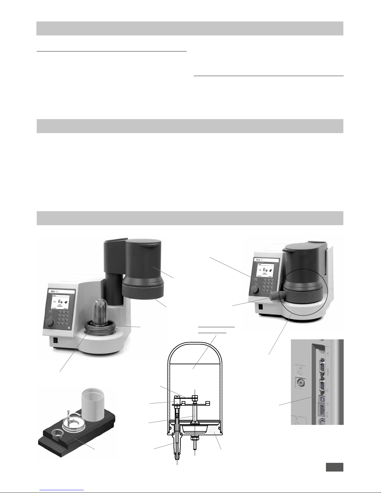
Interfaces on
rear of the unit
Controller unit with
display, Multifunctional
element and keybord
Inner vessel (IB)
Manual,
pivotable lift
A
A-A
Base
Ignition wire
Ground electrode
Ignition
electrode
Crucible
holder
Sectional view
inner vessel
Measuring cell as
a pressure vessel
Rotary
handle
Threaded nut
Threaded base
• 1 O-ring FPM 3.1 x 1.6
• 5 O-ring FPM 3.0 x 1.5
• 5 O-ring FPM 48.0 x 2.0
• 1 Quad-Ring NBR 92.0 x 4.5
• 1 X-Ring NBR 6,07 x 1,78
• C 1.104 water bath additive
• C 723 Benzoic acid
• C 1.1012 Organizer
• 4 base
• O-ring-grease Molykote 55
• Handle
• Operationg instructions C 1
• Safety instructions C 1/C 6000
• Technical information C 1
• Insert sheet C 1 (4 steps to use)
• Warranty card
C 1.1012
Organizer
Transportation, Storage
Scope of delivery
Description of the system components
Page 7
7
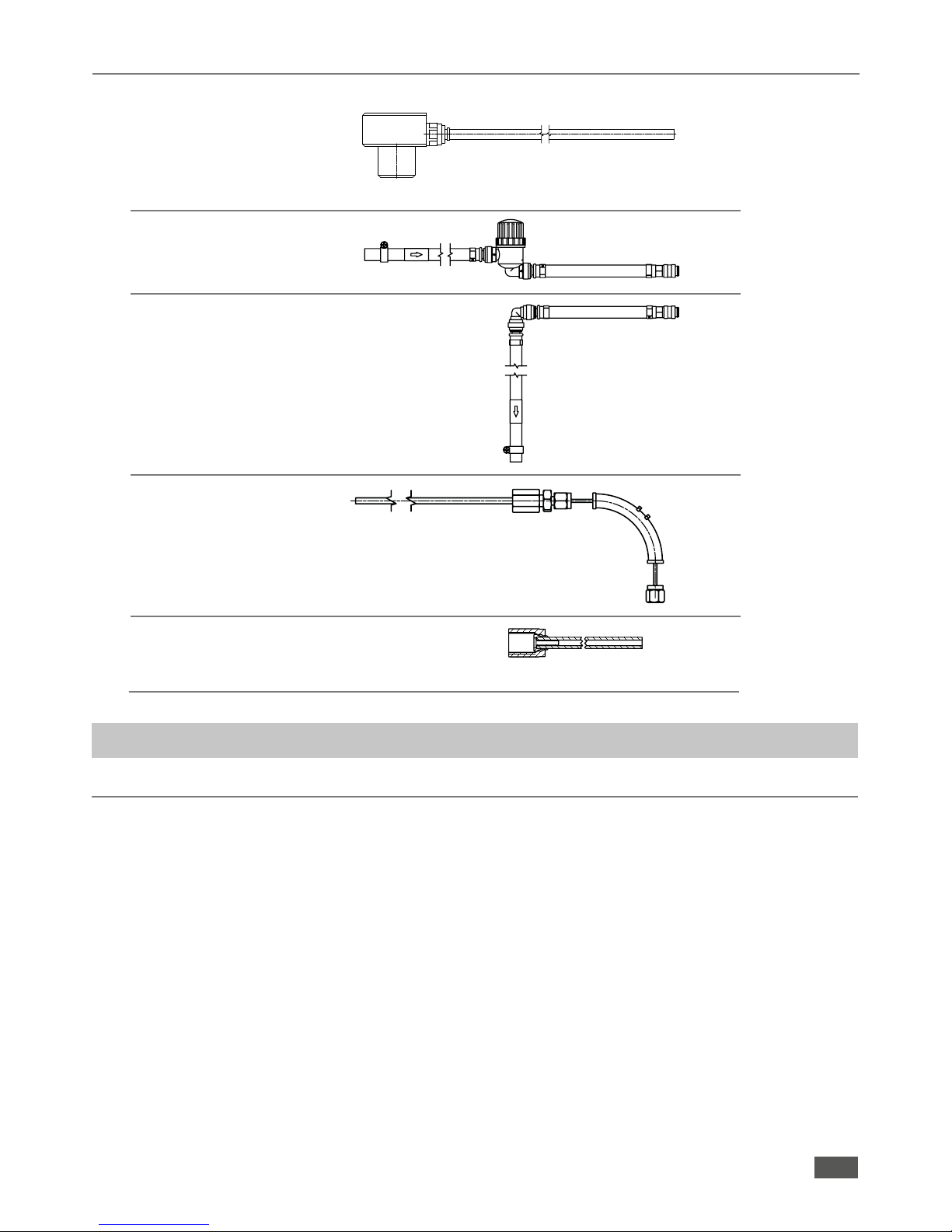
Hoses
• Discharge hose
• Inflow conduit
• Return conduit
• Venting hose
• Connection tube
SW8
Cooler
C 1
C 1
Cooler
C 1
C 1
(O)
C 1
(degas)
(water in)
(water out)
(overflow)
filter 10m
Cooler
Exhaust
air
Pressure reducer C 29
Adapter
SW10
Place of installation
A constant ambient temperature is an important requirement
for ensuring the high measuring accuracy of the system. The
following conditions must therefore be fulfilled at the place of
installation:
• No direct solar radiation
• No draughts (e.g. beside windows, doors, air conditioning)
• Sucient distance to radiators and other heat sources
• The minimum distance between the wall and the rear side
of the device must be at least 25 cm.
• The system must not have laboratory hardware such as
shelves, wire ducts, ring lines, etc. installed above it.
• The (constant) room temperature should be around
20 °C ... 25 °C.
• The system must be set up on a horizontal surface.
For operation of the system the following must be available at the
place of installation:
- A power supply corresponding to the nameplates on the system
components,
- An oxygen supply (99.95 % pure oxygen, quality 3.5; pressure
30 bar) with pressure gauge.
A shut-off valve for the oxygen supply must be installed. Observe
the instructions on handling oxygen given in the chapter “Safety
instructions“.
Observe the instructions on handling oxygen given in the chapter
“Safety instructions“. Please read these operating instructions
carefully.
IKA® consider themselves responsible for the safety,
reliability and performance of the appliance only when
• the device has been operated in accordance with the
operating instructions
• the specifications for the place of installation have been met.
max. 1.5 bar
Commissioning
Page 8
8
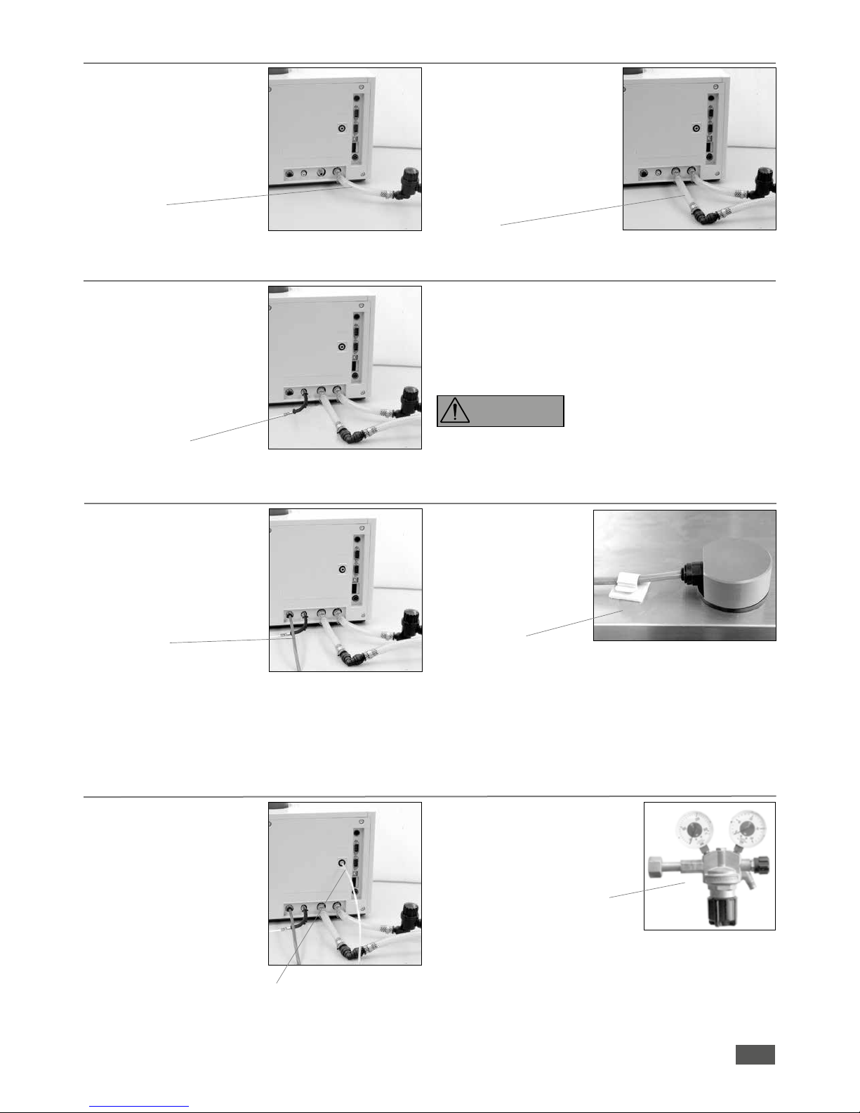
Cooler connection
1. Connect the inflow pipe to the
quick coupling to the “water
in“ (on the calorimeter) port.
Connect the other end of the
radiator side of “water out“
and tighten the hose clamp.
Inflow pipe
Return pipe
2. Connect the return pipe to the
quick coupling to the “water
out“ (on the calorimeter) port.
Connect the other end to
“water in“ (on the cooler) and
tighten the hose clamp.
Venting hose connection
1. Screw the venting hose to
to “degas“ screw coupling
(SW8; on the calorimeter) and
lay the free end in the extractor.
Connect the free end to a gas
scrabber gadget.
Venting hose
Observe the applicable safety regulations..
The combustion gases are vented from the decompstion vessel
after each combustion test on the vent hose. The vent hose must
not be kinked or pinched during installation.
3. Do not use distilled or demineralized water (increased
risk of corrosion)! Fill the cooler according to the cooler
operating instructions. is recommended in drinking tap water
quality. Mix in (max. 1 ml for 4-5 l of water) of the supplied
water additive. Thus, the durability of the water is improved..
4. Adjust the cooler temperature corresponding to the calori meter operating temperature.
Drain hose connection
1. Insert the drain hose fully into
the “tap-water“ connection
(on the calorimeter). Lay the
other end of the drain hose to
the cooler filler neck.
Drain hose
2. Secure the hose end with
an attachable adhesive
protection.
The hose end must always
have free access of air and
never immerse themselves
in the cool water!
Cooler
Oxygen supply connection
1. Insert the connection tube fully
into the coupling (“O
2
in“; on
the calorimeter) and connect
the free end on the pressure
reducer
IKA® C 29 (possibly
with the C 29 adapter, included with).
Connection tube allowable
operating pressure 40 bar
IKA
®
C 29 Pressure reducer
Combustion gases are dangerous
to health, so the venting hose
must be connected to a suitable
gas cleaning and extraction.
DANGER
Page 9
9
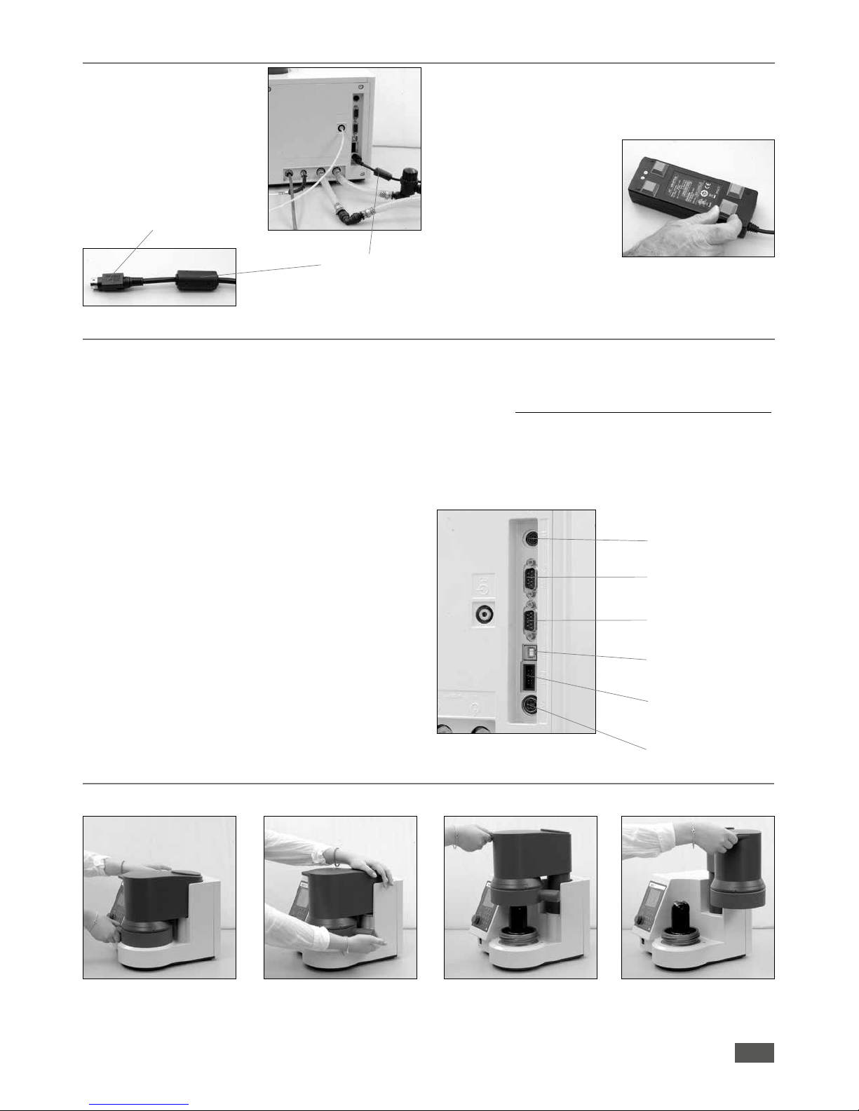
Power supply unit connection
1. Connect the power supply
connecting cable (24 V)
NOTE: Note the correct inser tion position (flat side
of the connector
pointing to the right).
Connecting cable
The desktop power supply (scope of delivery) must not be placed
flat on the laboratory table. It must be protected against moisture
and water penetration and must not be wet.
2. Tape the supplied rubber feet
to the power supply.
Place the power supply on the
rubber feet.
Connect the connection cable
to the DC power supply to
your supply network
(100-240V AC 50/60 Hz).
flat side of the connector
Connection of peripherals
Heating: Control output for the connection of the
IKA®
heating.
Scale: RS232 interface for connection of a scale
(Mettler, Ohaus, Sortorius, Kern)
Interface parameters: Baud rate: 1200
Data its: 7
Parity: odd
Stop its: 1
Handshake: none
PC/Printer: RS232 interface for connecting a PC to control
the C 1 (CalWin
®
C 6040) or a
printer to output the
measurement data.
Interface parameters: Baud rate: 9600
Data its: 8
Parity: none
Stop its: 1
Handshake: none
USB-B: USB device interface for connection the calori-
meters to the PC (CalWin
®
C 6040).
The connection simulates a serial interface on the
PC.
Installation:
After the C 1 was connected with the supplied
data cable to the PC, the C 1 tells the Windows
operating system, which device driver is required.
24 V =
Programming (Prog)
interface
USB-B (USB)
PC / Printer (PC)
Scale (balance)
Heating (ext)
This driver can be downloaded from the
IKA® website.
Find your driver at the following website:
http://www.ika.com/ika/lws/download/usb-driver.zip.
Programming-
(only for service)
interface:
24V= 24 V Voltage input for the included power
supply table.
Handling the unit
1. Opening the unit
The closing of the unit in the reverse order
Q
h
h
1
2
Q
Page 10
10
2. Removing the inner vessel
Inserting the inner vessel takes place in the reverse
order
h
3. Removing the inner vessel base
h
4. Switch on the device
Open the device and
switch the device on
and off with the front
power switch.
h
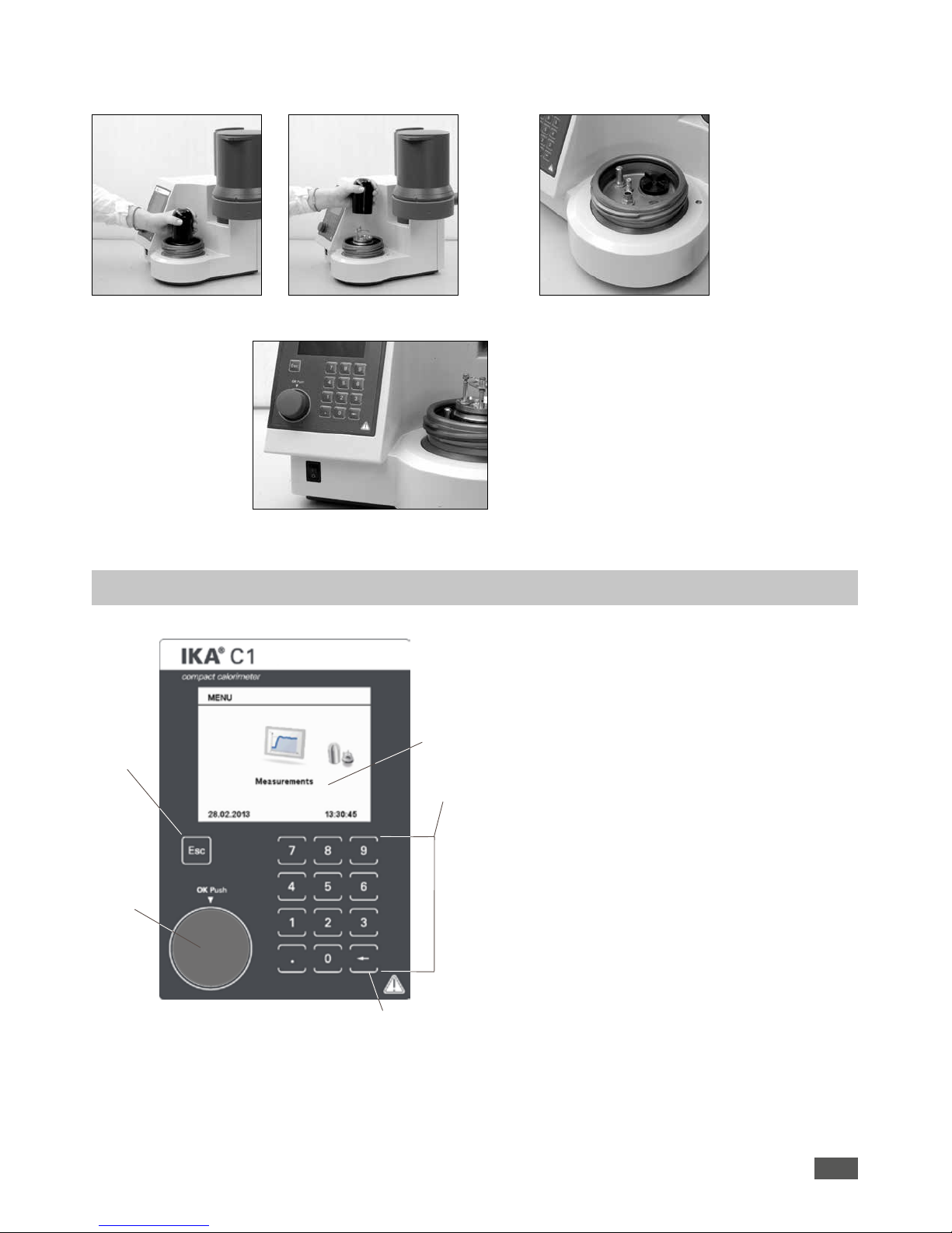
Display
Numbers
bloc
Del button
Multifunction
element
Esc button
Display: View system information, test data, as well as
menus and dialog boxes for the data input
Numbers bloc:
Entering numbers and decimal points
Del button: Deleting an entered character string to the left of
the cursor (eg the weight of a combustion
sample)
Multifunction element
Made possible by turning the scroll and select
menu items, as well as by pressing the Change
and confirm input values
Esc button: The Esc-(Escape) function is active in the menu
structure, the input window and input fields.
• In the menu structure (if any) change to the
parent menu
• In the input window is changed to the higher
level menu structure
• When the ESC button is pressed in an editable
field, the editing is finished and the original
value is restored.
Q
Control unit with display
Page 11
11
Dialog box
The dialog boxes are equipped with the following elements:
Menu-heading
Selected menu item
(blue)
Scrollbar
Menu options resp. user notification
Editable
input field
(yellow)
Status field
• ‚Back‘:
Closing a info window without information input
values and return to the parent menu.
Also possible using [ESC].
• ‚Accept‘:
Closing a window. Changes made are saved by
the system.
• ‚Start‘:
Starting a measurement.
• ‚Details‘:
Detailed information during a running
measurement.
• ‚Graph‘:
View graph during a running
measurement.
Editable input field:
They can be enabled for value entry by pressing
the multi-function element. The background color
of the active field is indicated in yellow. By using
the numeric keys or by turning the multi-function
element, the input values can be changed.
Status field:
Display the device status, which is important for
the user and operation.
Menu-heading:
The name of the currently displayed window
Selected menu item:
The blue background (cursor) marks the selected
item. The position can be changed by
turning the multifunction element.
Scrollbar: If a menu window more entries can be displayed as
the current is displayed a scrollbar.
Turn the multi-function element, the other menu
items are visible.
User notifications:
Some windows have a field in the user notes will
be displayed.
Menu options:
They allow a “getting ahead“ from the current
window.
In the following example, the most frequently
displayed menu options are listed and described:
• “Break off“:
Closing a window, the changes made will not be
accepted by the system.
Also possible using [ESC].
On confirmation changes
will be applied
On confirmation
changes will not be
applied
Page 12
12
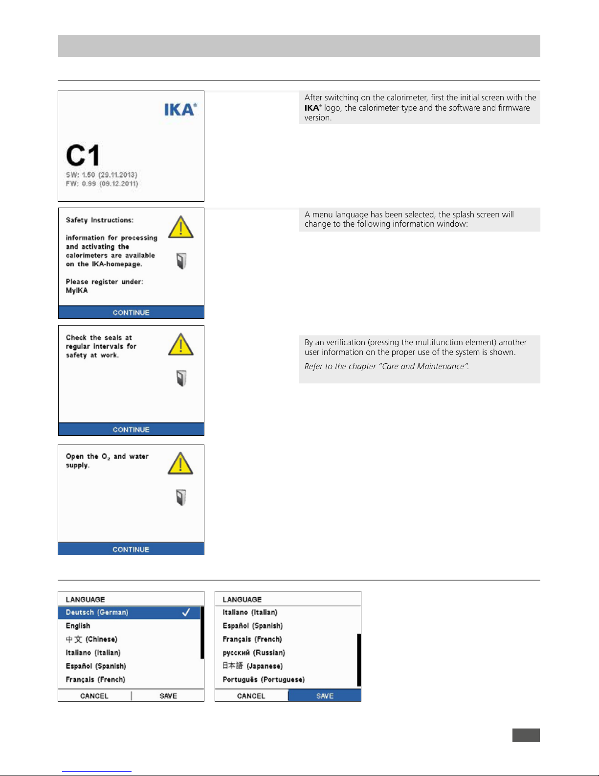
A menu language has been selected, the splash screen will
change to the following information window:
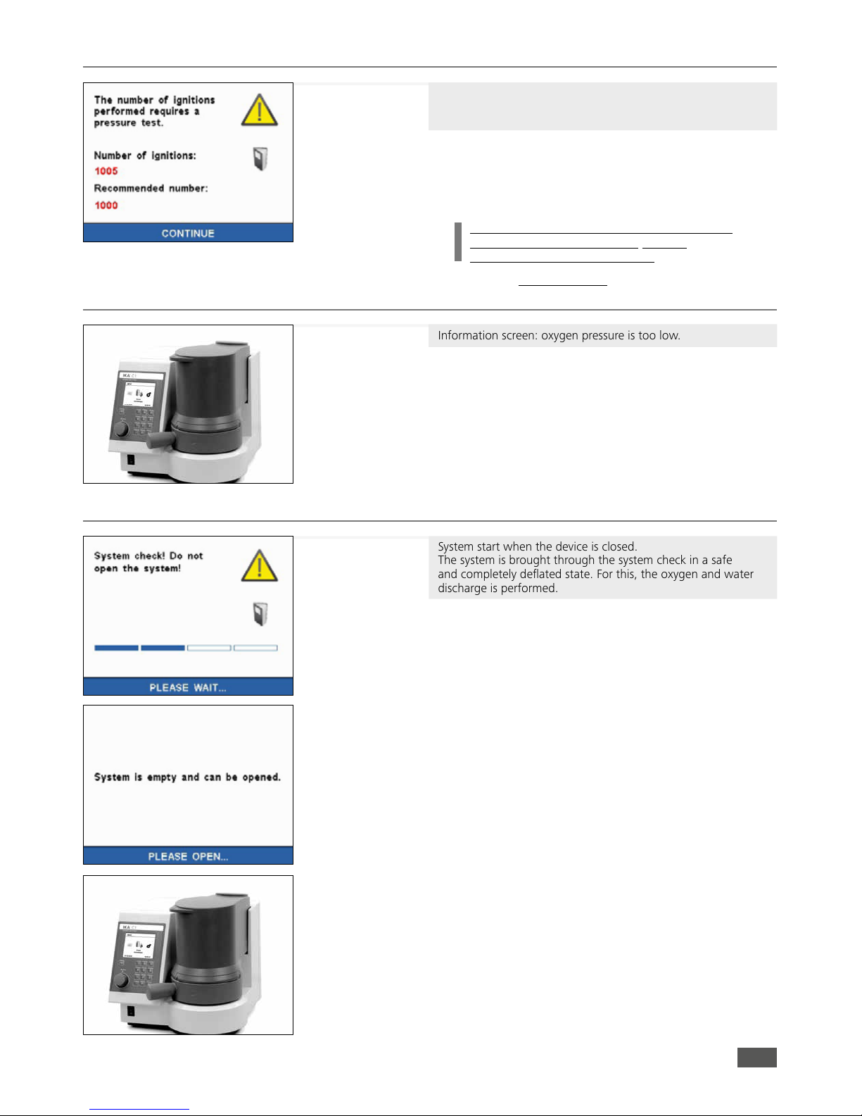
INFO: Exceed the number of ignitions devices, the maximum
recommended number of ignition, a pressure test must
be performed with the device.
An additional information window is displayed.
See capture - “Pressure test“
INFO: If the oxygen pressure is too low, a corresponding user
information is displayed.
See capture - “Oxygen pressure too low“
By an verification (pressing the multifunction element) another
user information on the proper use of the system is shown.
Refer to the chapter “Care and Maintenance“.
INFO: When the system is closed, a purge routine is started.
See capture - “System check“
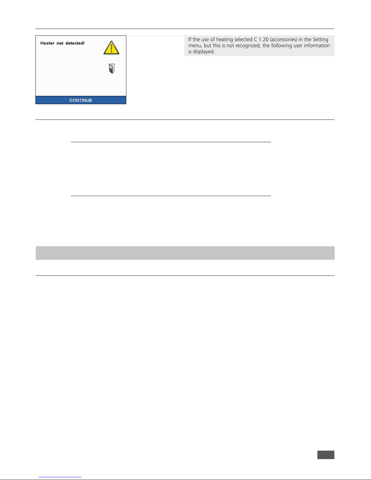
INFO: Has been selected in the settings menu under accessories
heating option, but this is not detected, user information
is displayed.
See capture - “Heating detection - System start“
Switching on the system (in the open state)
After switching on the calorimeter, first the initial screen with the
IKA® logo, the calorimeter-type and the software and firmware
version.
INFO: Upon initial system start, the menu language must be
selected.
See capture - “Selection of language“
Selection of language
System start
Page 13
13
Pressure test
Oxygen pressure
Information screen: oxygen pressure is too low.
NOTE:
The calorimeter C 1 required for functionality an oxygen
pressure of at least 20 bar.
Reproducible measurements for a working pressure
of 30 bar is required.
System check
System start when the device is closed.
The system is brought through the system check in a safe
and completely deflated state. For this, the oxygen and water
discharge is performed.
Here, the following information screen is displayed:
INFO: During the system check detected no oxygen or the oxygen
pressure is too low, the following error message is displayed:
A pressure test must be performed after a decomposition vessel
has reached or exceeded the recommended number of ignition
cycles.
Once the pressure test has been performed a release code can be
entered to enable the unit to be used for further measurements.
The warning message will then disappear. The enable code can
be in the following screen, by pressing the “Next button“ to be
entered.
INFO: Using the unit may be further worked.
Contact for performing the pressure test, the
service department from
IKA® Works.
Observe the safety instructions!
service@ika.de
Page 14
14
Heating detected
If the use of heating selected C 1.20 (accessories) in the Setting
menu, but this is not recognized, the following user information
is displayed.
NOTE:
Check that the heater is correctly connected and turned on.
Factory settings
Settings:
• Menu: animated
• Color palette: white
• Key tones: on
• Date device: 01.01.2012
• Time device: 00:00:00 Uhr
• Units: J/g
• Heating: off
• Disposable crucible: no
• Printer: off
• Service Info: no
• Scale: off
Basic settings:
• C-value IB1: 0
• C-value IB2: 0
•
Reference calorific value:
26457
• Start temperature: 22 °C
•
HO Combustible crucible
: 19839
• QExternally 1: 50
• QExternally 2: 0
• Controlled time: off
• O rinsing: off
• Cooling: on
• Prolonged venting: 0
As delivered, the C 1 calorimeter system is configured as follows:
Test condition
Combustion is carried out in a calorimeter under specific
conditions.
The
IKA® C 1 is filled with a weighed fuel sample, the fuel sample
is ignited and the temperature increase in the calorimeter system
measured.
The specific calorific value of the sample is calculated as follows:
• Weight of fuel sample
• Heat capacity (C-value) of calorimeter system
• Calculated temperature increase of water in the calorimeter
system
For complete combust on the inner vessel is filled with pure
oxygen (quality 3.5). The pressure of the oxygen atmosphere in
the inner vessel is max. 40 bar.
The exact determinat on of the gross calorific value of a
substance requires that the combust on proceed under precisely
defined conditons. The applicable standards are based on the
following assumptons:
• Depending on the start temperature that is set, the tempera ture of the fuel before the combustion is 20 °C upto 30 °C.
• The water contained in the fuel before the combustion and
the water that is formed when compounds comprising the
fuel containing hydrogen undergo combustion is present in
a liquid state.
• No oxidation of the atmospheric nitrogen has taken place.
• The gaseous products after combustion consist of oxygen,
nitrogen, carbon dioxide, sulfur dioxide and the oxidation
products of the sample.
• Solid substances may be formed (for example ash).
Often, however, the combustion products that form the basis
of the standards are not the only products that are formed. In
such cases, an analysis of the fuel sample and the products of
combustion are necessary to provide data for a correction calculation. The standard gross calorific value is then determined
from the measured gross calorific value and the analysis data.
The gross calorifc value Ho is formed as the quotient of the
amount of heat liberated upon total combustion of a solid or
liquid fuel and the weight of the fuel sample. The compounds
comprising the fuel that contain water must be present in liquid
state after the combustion.
The heat value Hu is equal to the gross calorific value less
the energy of condensation of the water that was contained
in the fuel and was formed by the combustion. The heat value
is the more important quantity for technical purposes, since in
all important technical applications, the heat value is the only
quantity that can be evaluated in terms of energy.
For information on the fundamental principles of calculation for gross calorific value and heat value, please refer
to the applicable standards (for example: DIN 51 900;
ASTM D 240;ASTM D 1989, ISO 1928).
Determination of gross calorific value
Calorimetric measurements
Page 15

15
Fuel
sample
Burning
aid
Igniter
Formation of
sulphuric acid
Formation of
nitric acid
Heat quantity from:
External energy
Corrections
As determined by the system, during a combustion experiment,
not only is heat generated from the combustion of the
sample, but heat also occurs in the form of extraneous energy.
This may fluctuate considerably in proportion to the heat energy
of the fuel sample.
The combustion heat of the cotton threat that ignites the sample
and the electrical ignition energy would result in distorted values
of the measurement. This effect is taken into consideration in the
calculation with a correction value.
Substances with low flammability or substances that burn poorly
undergo combustion in combination with combustion aids.
The combustion aid is first weighed and then added to the crucible
with the sample. From the weight of the combustion aid and its
known specific gross calorific value, it is then possible to determine
the quantity of heat that is introduced thereby. The result of the
experiment must be corrected by this amount of heat.
The C 14 disposable crucible is a combustible crucible that can
be used instead of a traditional crucible. The disposable crucible
undergoes total combustion with no residue. If a disposable
crucible is used, there is then no need for a cotton thread. The
crucible is in direct contact and is ignited by the fixed ignition
wire of the inner vessel.
Inner vessel in which the combustible crucible is to be used, must
be fitted with an additional overlay (see accessories). The sample
is weighed directly into the disposable crucible. In most cases, no
additional combustion aid is necessary because the disposable
crucible itself acts as the combustion aid.
Acid correction
Almost all substances to be analyzed contain sulfur and nitrogen.
Under the conditions that pre-vail during calorimetric measurements, sulfur and nitrogen undergo combustion and form SO2,
SO
3
and NOX. Sulfuric and nitric acid arise in combination with
water resulting from combustion and humidity. Heat of solution is
also generated. To obtain the standard gross calorific value, the
effect of the heat of solution on the gross calorific value is
corrected.
To obtain a defined final status and to record all acids quantitatively, approx 5ml distilled water or another suitable absorption
solution is placed in the inner vessel. With this absorption fluid
and the combustion water, the combustion gases form acids.
After the combustion, the decomposition vessel is thoroughly
washed with distilled water so as to collect the condensate that
has settled on the inner wall of the vessel as well. The solution
obtained in this manner can now be examined with a suitable
peripheral detection device for aqueous decomposition into the
respective acid content.
For more information on this subject, please contact
IKA®‚ or
your nearest authorized dealer.
When calculating the energy value in C 1 external energies are
taken into account from kiln furniture, however, there is no
correction of acid. The calorific value is not calculated.
To do this, use the calorimeter software
IKA® CalWin®.
The calorimeter system
IKA® C 1 is a precision measuring instru-
ment for the routine determination of calorific values of solid and
liquid substances. Exact measurements can however be achieved
only if the individual steps of the trial are performed with care.
The procedure as described in the “For your safety“ section 1 and
in the following sections must therefore be adhered to exactly.
If you are burning unknown samples,
leave the room or keep well away
from the calorimeter!
A few points should be noted in respect of the substances to be
combusted:
• Normally, solid substances can be burned directly in powder
form. Rapidly burning substances (for example benzoic acid)
must not undergo combustion in loose form.
Benzoic acid must only be burned in the form of pellets! Com bustible dust and powder must be compressed into pellets
before combustion. Oven-dry dust and powder such as wood
chips, hay, straw etc. burn in an explosive manner! They must
be moistened first! Readily combustible liquids with a low va por pressure must not be come in direct contact with the
cotton thread (e.g. tetramethyl dihydrogen disiloxan).
Notes on the sample
Rapidly burning substances tend to squirt. Such substances
must be pressed into tablets before combustion. Suitable
for this is e.g. the
IKA
®
pelleting press C 21.
• Most liquid substances can be weighed directly into the cru cible. Liquid substances exhibiting turbidity or containing water
that will settle out must be dried or homogenized before they
are weighed in. The water content of these samples must be
determined.
• Highly volatile substances are placed in combustion capsules
(gelatin capsules or acetobutyrate capsules, see “Accessories“)
and undergo combustion together with the capsules.
• For substances with low flammability or low calorific substances
use combustion aids (see “Accessories“). Before the capsules or
the combustion bag is fi lled with the substance to be deter mined, it must be weighed in order to determine the additional
extraneous energy introduced into the system from the weight
and the gross calorific value. This is taken into consideration
with QExtern2. The amount of combustion aid should be as little
as possible.
The external energy must be determined externally.
DANGER
Page 16

16
To correctly determine the gross calorific value, it is of fundamental importance that the sample undergoes complete combustion.
After each experiment, the crucible and all solid residues must be
examined for any signs that combustion was not complete.
In case of using substances tending to squirt it is not possible to
ensure complete combustion.
Substances with low flammability (substances with a high
content of mineral matterand low-calorific substances) will often
Complete combustion
undergo complete combustion only with the aid of combustion
capsules or combustion bags (C 10/ C 12 see “Accessories“). It is
also possible to use liquid combustion aids such as paran oil.
The combustion aids as well (for example the cotton thread) must
undergo complete combustion. If unburned residues are left over,
the experiment must be repeated.
To ensure precise, reproducible results of the measurement, the
calorimeter system is calibrated after it is initially placed in service,
after service jobs, after parts are replaced and at specific time intervals. During calibration, the heat capacity of the calorimeter system
is redetermined.
Regular calibration is absolutely essential to obtain accurate
measurements!
For this purpose, a specific quantity of a reference substance
undergoes combustion in the
IKA® C 1 under the conditions of
the experiment. Since the gross calorific value of the reference
substance is known, it is possible after combustion has occurred
Calibration
to calculate the heat capacity based on the increase in temperature
of the calorimeter system. The reference substance for calorimetry
on an international level is benzoic acid of the National Bureau of
Standards (NBS Standard Sample 39 J) with a guaranteed gross
calorific value.
For more detailed information on calibration please see the relevant
standards.
If the
IKA® C 1 is operated with several different decomposition
vessels, you will need to determine the heat capacity of the system
for each decomposition vessel. The parts of each decomposition
vessel must then not be swapped with parts from other vessels.
Ensure that calibration is carried out under the same conditions as
the subsequent tests. If substances are used in the decomposition
vessel in combustion tests (e.g. distilled water or solutions), you
must use exactly the same amount of this substance for calibration.
Notes on calibration
For determination of calorific values the increase in temperature
must be about as great as for the calibration (± 30%). 1g benzoic
acid =˜ 6K. The optimum sample quantity must de determined by
several trials where necessary.
• Under the conditions that prevail during calorimetric mea surements, sulfur and nitrogen un-dergo combustion and form
SO2, SO3 and NOX. Sulfuric and nitric acid arise in combinati on with the water resulting form combustion. Heat of solution
is also generated. This heat of solution is taken into conside ration in calculating the gross calorific value. In order to quanti tatively record and determine all acids that have been formed,
about 5 ml of distilled water or another suitable substance can
be added to the decomposition vessel before the experiment.
The calibration of the system must have been performed in
accordance with the instructions!
Remove after measuring the complete inner vessel. Turn the inner
container upside down, loosen gently the internal container bottom. Rinse thoroughly with distilled water, the inner area of the
inner container. The rinsing water and the solution formed from
the water that was added are combined and the acid content of
the combined solution is examined. If the sulfur content of the
combustion aid and the nitric acid correction are known, the water
does not need to be analyzed.
These correction values can not be entered in C 1. For this, use the
IKA® calorimeter software CalWin®.
To increase the service life of parts to wear and tear (O rings,
seals etc.) we recommend to work with water added to the
experiment as a matter of general principle.
Halogen rich substances can cause corrosion on the inner container.
These substances must not be burned in C 1 with the
standard inner vessel.
In halogen-rich substances of special halogen-resistant
inner vessel C 1.12 must be used.
Handle
h
h
h
Page 17

17
The user has two display modes are available.
Measurements
The following submenus are available:
• New measurement
• Last result
• System test
• Measurement archive
• Calibration archive
• Memory overview
Default settings
The following submenus are available:
• C-value IB1
• ID IB1
• C-value IB2
• ID IB2
• Ref. cal. value
• Ho Comb. cruc.
• Start temperature
• QExtern 1
• QExtern 2
• O2 rinse
• Cool Down
• Extend. O2 Emptying
Animated view List view
Settings
The following submenus are available:
• Date / Time
• Units
• Display / Keypad
• Language
• Accessories
• Cooler test
Overview Main menu
Page 18

18
Maintenance
The following submenus are available:
• Change seal
• Test stirrer
• O2 System blow
• Servo up
• Servo down
INFO: When performing maintenance programs, the system
must be open !
Information
The following informations are available:
• Software
• Firmware
• Serial number
• Service
• Pressure test
• Ignitions
• Next test
• Support
The term “measurements“ below refers to both the measurements to calibrate the calorimeter system (calibration measurements) and the actual measurements for determining the calorific
value. The difference lies mainly in the evaluation, whilst preparation and performance make virtually no difference.
Performing the measurement
Select and confirm “Measurements“ in the main menu with the
multi-function element.
In the submenu select and confirm the option “New
measurement“.
Preparing and performing measurements
Page 19

19
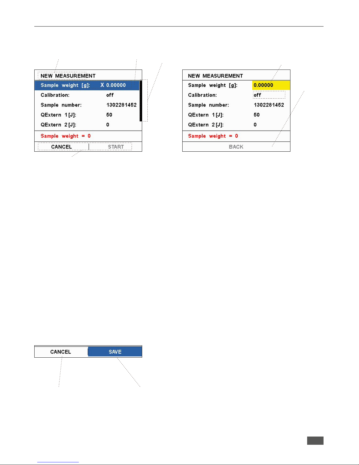
Input window NEW MEASUREMENT
Select and confirm the menu item “Sample weight“. Enter the
sample weight with numeric keypad and confirm.
INFO:
A distinction is made between the use and non disposable
cup. Use of disposable crucible can be selected in Settings
" Accessories.
INFO: For automatic input of the weight may be a connected
scale can be used
INFO: The inputted weight values are checked for permissibility.
INFO: The existing store will be reviewed after the entry of a
new measurement / calibration and a user note displayed
if it is not possible to save the measurement / calibration.
NOTE:
Ensure that a maximum energy input of from 40,000 joules is not
exceeded.
NOTE:
For more, detailed descriptions of the individual menu items are
treated in the chapter “Calorimetric Measurements“.
INFO: If a scale is used in activation of the input field, the
weight is automatically queried. It can be pressed on the
scale alternatively, the transmit button.
Fill in the sample weight.
Calibration off.
When you are ready with your input, press “OK” button.
Don’t close the C 1 before you have pressed “OK“
button!
During the prerequisite checking, the cotton thread can be
attached to the ignition wire, hung the crucible in the provided
holder and the sample are contacted with the ignition wire.
Placing the sample
When using a disposable crucible of contact between the ignition
wire and the combustible crucible must be present. The fixing of
the cotton thread is not necessary.
Page 20

20
To increase the service life of wearing parts (O-rings, seals,
etc.) it is advisable to always work with a water template.
Generally, the test sample must be selected so that the temperature elevation during the measurement is below 10 K and
the temperature increase of the calibration comes close (max.
energy input: 40,000 J). Such exposure may damage the
calorimeter.
When exceeding the maximum energy input is recommended
to return the calorimeter.
To determine the potential energy initially very small sample
weights (approx. 0.2g) must be chosen when working with
unknown substances. If you burn unknown samples, leave
the room or keep your distance from the calorimeter.
If distilled water or solutions presented in the decomposition
vessel during the combustion experiment, the calibration
with the same template must have been performed before.
Close the calorimeter
After the sample is loaded and the contact with the ignition wire
is present and the inner vessel was placed, the calorimeter is
sealed.
The following screen informs the user whether the system is
closed properly and securely.
Are combustion vessel and the complete system properly closed,
the measurement starts automatically.
Note:
Can the inner container and / or closure ring with handle heavy
wire, please follow the instructions for oiling the seals!
2. Weigh the substance with an accuracy of 0.1 mg directly into
the crucible.
Where appropriate distilled water or a solution must be
presented in the inner vessel.
The input of the maximum possible sample weight is limited to a
maximum of 5 g.
1. Attach with a loop a cotton thread centered on the ignition
wire (at the open calorimeter).
The inner container base remains in the control of sample preparation in the calorimeter. But you can also use it by pulling it out
individually, or for consequential - Analysis - determinations, refer
to the closed inner container.
The following preparations must be made to prepare the system
for a measurement:
Preparing a measurement
C 6 Quartz crucible
h
Impression for distilled water or a
solution as a template
Page 21

21
Prerequisite checking for a measurement
When checking the preconditions for a measurement using a
distinction is made with and without C 1.20 heating between. The
following points should be checked:
• Existing Ignition
• Sucient oxygen present
• Open water connection
• Tempered water or using a heating their functionality
• Ignition:
Checking whether ignition contact available
• Oxygen pressure:
Check whether the system has suciently high oxygen pressure
has to make a measurement
• Water detected:
Check whether the system has detected water
• Limit ≤ Water ≤ Start temp:
Check whether there is the current water temperature within the
permissible temperature range
Without
C 1.20
heating:
• Heater test:
Check the heating functionality
With
C 1.20
heating:
Measurement procedure
During a measurement, different phases are passed through.
These phases are described below
• Phase 1:
Filling the calorimeter with water
• Phase 2:
Filling the calorimeter with oxygen (Note: If the option-O
2
flushing under the main menu " Basic Settings is selec ted, the inner vessel is two times with Oxygen rinsed)
NOTE:
Alternatively, to display the graph may also have a detailed
view of be selected with the following information:
• Current temperature:
Mean value of the actual temperatures
• Ignition temperature:
the currently measured temperature
• Measurement time:
Display: duration of the measurement
• Fill time:
Filling the inner vessel with water.
The fill time is user specific and must be kept constant
on each measurement. Check the filter where long fill times
are used.
NOTE:
After switching on the calorimeter C 1 or after a break of 2
hours during the filling of the calorimeter C 1 is still carried
out an intermediate emptying (H2O - purge). Once the
water sensor detects water, the stirrer is switched on.
After a short waiting period begins phase 2.
Page 22

22
• Phase 3:
Filling with oxygen
• Phase 7:
Venting, result is displayed
• Phase 6:
Post test
• Phase 8:
Cooling (if option under the main menu " Basic Settings
" cooling is enabled) and water emptying
NOTE:
With the “cooling“ option, the energy is absorbed (by the
combustion in the calorimeter entered).
Deactivation, the measuring time and the accuracy of the
calorimeter affecting (depending on the sample
throughput).
• Phase 5:
The system ignites and thereby starts the main test
INFO: An ongoing measurement can be stopped by selecting
“Cancel“ at any stage
• Phase 4:
Stabilizing the temperature and preliminary
Page 23

23
• Phase 9:
The system is completely emptied, and can be opened.
The inner vessel can be taken down. Through a visual check
is necessary to ensure that the sample in the crucible was
combusted completely.
After each combustion are all parts of the inner vessel that come
in contact with the combustion products to clean condensate.
It is sucient to parts with an absorbent, lint-free cloth to wipe
off. Combustion residues in the inner vessel, for example, soot
or ash are eliminated in the same way. Can not be cleaned in
the manner described (eg due to burn-in or pitting corrosion) of
Cleaning the inner vessel
the inner vessel, it shall be subjected to no cases of mechanical
cleaning.
Please contact in such cases, contact your local service center or
send the inner vessel for inspection and cleaning to our factory.
Follow-up measurement
By pressing the multi-function element, the result display returns
to the measurement sub-menu and the next attempt can be
started.
Use of a disposable crucible
The disposable crucible can optionally be used instead of metal
or quartz crucible and burned during the measurement complete
(see chap. “Accessories“).
INFO: 50 Joule omitted. With the combustible crucible not a
cotton thread is used.
Display the storage overview
If after pressing the “New Measurement“ button, the memory
overview is displayed, the capacity of the storage spaces for
measurements / calibrations are almost depleted. If the maximum
number is reached, no new measurements / calibrations more can
be saved for this mode. By pressing the OK key to access the screen
“New Measurement“. Delete measurements / calibrations are no
longer needed.
Result Display
NOTE:
Because the calorimeter C 1 (all internal parts) still not in a
first measurement at operating temperature, the result of
the first measurement can differ significantly from the
subsequent measurements of a test series.
We therefore recommend not to evaluate the outcome and
possibly to delete.
Alternatively, a system test can be performed,
see chap. “System Test“.
Page 24

24
Example: sample weight in the limit and initial weight of the
combustible crucible too high
Using a scale
About Settings " accessories can be selected using a scale.
If this option is selected, the displayed on the scale weight is
automatically transmitted to the selected weight input field.
Depending on type of balance this function may need to be be
activated on the scale or the Transfer button must be pressed.
This applies both to the initial sample weight of the sample and
the weight of the disposable crucible.
Permissible weight entries
In a non-permissible weight is the OK button inactive (grayed out)
and can not be selected..
• Sample weight:
There are weights of 0.00001 g to 4.99999 g permitted!
From 2.5 g in addition the message appears that the sample
weight in the limit range is (initial mass in the limit).
• Combustible crucible:
There are weights of 0.00001 g to 0.99999 g permitted!
Weights greater than 0.99999 g are not possible.
Confirm the selection with OK button.
Page 25

25
Cancel a measurement
An ongoing measurement can be canceld at any time.
After ignition, the system waits for 1 minute with the emptying,
as otherwise there is a risk that the sample is not completely
burned.
After confirm the cancellation, the system automatically emptied
and bring it to a safe state. The calorimeter can be opened and
you can return to the main menu.
New measurements
• New measurement:
Preparing and starting a measurement
• Last result:
Displaying the result of the last measurement
• System test:
The functionality of the calorimeter is checked
• Measurement archive:
The system can store up to 100 measurements
• Calibration archive:
The system can be used for both modes of operation (22 °C,
and 30 °C) for each inner container (1 and 2) each
storing 15 calibrations.
• Memory Summary:
Display the memory summary
Last result
This screen shows the results of the measurement carried out
previously successfully.
Measurements
Page 26

26
System test
Functional testing of the system
Use for the system test one or two benzoic acid tablets.
Alternatively, however, for example, an appropriate amount of
sugar or an alternative fuel to be used.
The system test is used to test the functionality of the overall
system. For this purpose all switching operations are carried out,
which take place in a normal measurement. If the system test
performed without error, the functionality is guaranteed.
The system test can be used to create a quick ˝warm up“ the
system. It is faster than a normal measurement, since there is no
analysis and improves the accuracy of the first measurement so
that they need not be discarded
Measurement archive
In measurements Archive up to 100 measurements can be stored.
A measurement taken is automatically added to the archive.
Displays the line number, the name of the measurement as well
as the result.
Further details are displayed by clicking on a measurement.
Page 27

27
Measurement archive: Edit
By clicking on the “EDIT“ button in the list view another screen
for selecting the edit mode.
Print:
• Measurements can be selected and printed
Delete:
• Measurements can be selected and deleted
Delete all:
• All measurements are deleted
By selecting one of these menu items to the list view is displayed
again. As a heading of the screen active editing is displayed. The
“EDIT“ button is replaced with an “OK“ button.
Measurement archive: Delete
By clicking the “OK“ button, the following dialog appears:
By confirming with “OK“, the selected measurements will be
deleted.
Measurement archive: Print
Click on the individual measurements they are selected and
marked with a green tick. By clicking again the selection is
reversed
By confirming the selected measurements with “OK“ followed
by the display of the user note. By confirming with “OK“, the
selected measurements are printed.
Page 28

28
Calibration archive
After selecting the appropriate archive is displayed.
INFO: In each calibration archive up to 15 calibrations can be
stored. A calibration performed is automatically added to
the appropriate archive
Displays the line number, the name of the calibration and the
result (C value).
Below the list of the current C-value of the system is shown (in
red). By confirming the multifunctional element details concerning
the measurement are displayed. For the C-value calculation, select
˝Edit“.
INFO: The C-value can also manually at Main Menu > Basic
settings entered alternative.
Calibration archive: Edit
By clicking the “EDIT“ button in the list view, another screen
appears to select the edit mode.
Selection C values :
• Calibrations can contribute to the redefinition of the C-value
be selected
Print:
• Calibrations can be selected and printed
Delete:
• Calibrations can be selected and deleted
By selecting one of these menu items to the list view is displayed
again. When heading of the screen active editing is displayed.
The “EDIT“ button is replaced with an “OK“ button.
Measurement archive: Delete all
By clicking the “OK“ button, the following dialog appears:
By confirming with “OK“, all measurements will be deleted.
Page 29

29
Calibration archive: C-Value selection
Click on the individual calibrations they are selected and marked
with a green tick.
By clicking again the selection is canceled and the new C-value
(mean value) is displayed below the list view directly.
By clicking the “OK“ button, the following user message appears:
By clicking the “OK“ button, the new value is accepted.
INFO: For RSD calculation of at least two C-values must be
selected. Otherwise, the result is Infinite and it is “Inf“ is
displayed as RSD.
Formula for calculating: X is a set of data (x1, .... xn)
and N the number
Relative Standard Deviation (RSD)
= (standard deviation / mean value) x 100
Mean value: X = X
Mean
= (Σ
N
n=1
xn )/N
Standard deviation:
σ =
√ Σ
N
n=1
(xn - X
Mean
)2/(N - 1)
INFO: The new value is also displayed under Main menu "
Basic settings.
Calibration archive: Print
Click on the individual measurements they are selected and
marked with a green tick. By clicking again the selection is
reversed.
By clicking on the OK button, the following user dialog appears:
By confirming with “OK“, the selected calibrations are printed.
Calibration archive: Delete
Click on the individual measurements they are selected and
marked with a green tick. By clicking again the selection is
reversed.
INFO: Calibrations that are used to the current C-value
calculation, can not be deleted.
She are grayed out and can not be selected..
By clicking the “OK“ button, the following user dialog appears:
By confirming with “OK“, the selected calibrations will be deleted.
Page 30

30
• C-value IB1; C-value IB2:
C value for the corresponding inner vessel
• ID IB1; ID IB2:
Identification number of the inner vessel
• Ref Energy:
Calorific reference value of benzoic acid
• HO Combustible crucible:
Calorific value of the combustible crucible
• Start temperature:
Changing the mode of operation between 22 °C and 30 °C.
• QExtern 1; QExtern 2:
Default values for the external energies 1 and 2
• O2 rinse:
The inner vessel can before the measurement of oxygen
be rinsed (2x with subsequent filling)
• Cool down:
Cooling the system after measurement
• Extend. O2 Emptying [min]:
0 - 99 adjustable
Settings
Date / Time
The setup menu contains the following menu items
• Date / Time
• Units
• Display / Keypad
• Language
• Accessories
• Chiller temperature
Setting the system time and date.
This data is used for automatic generation of a new measurement
name.
Units
The user can choose between the listed below unity
representations:
• J/g
• cal/g
• BTU/lb
• MJ/kg
NOTE:
When using a gas-washing station, the ventilation time
must be extended.
Default settings
Page 31

31
Display / Keypad
Inverted menu view
List view
Colour range black
Language
Selecting the system language
Colour range white
The user can access this menu
• select and change the background color of the display.
The background color can be selected either white or black
• the key tones on or off
• the appearance of the menus between animated view
and list view move
Page 32

32
Selection of accessories
• Heating:
Use of heating during the measurement C 1.2
• Combustible crucible:
yes / no
Weight input of the combustible crucible in the submenu “New
measurement“ can be done manually or by data transfer from
the balance.
• Printer:
Using a serial printer.
Selection option between:
• off: no expression
• briefly: expression
• standard: result expression with temperature values
• Service Information:
Service information is outputted via the serial interface
• Balance:
Selecting a balance type.
Selection option between:
• out
• Sartorius/Kern
• Mettler-Toledo
• Ohaus
Accessories
Chiller test
Viewing maintenance programs that can be performed by the
user at regular intervals.
Inner vessel and the inner vessel bottom lift out and set
aside.
Maintenance menu:
The system must be open to performing the maintenance programs.
The maintenance menu can be reached at Menu > Maintenance and contains the following points
Check whether the cooling water tem-
perature within the specified range of
19.5 +/- 1.5 °C at the wor-
king temperature 22 °C
or
27.5 +/- 1.5 °C at the wor-
king temperature 30 °C
is located.
Maintenance
Page 33

33
Change seal:
1 In the Menu Maintenance press “change seal“ button. This
requires oxygen pressure be present at C 1.
2 Unscrew the piston (Pos. 38 III) with screwdriver
counterclockwise
3 Remove the O-ring (Pos. 38 VI)
4 Put new O-ring on piston (Pos. 38 VI)
5 Screw in piston and tighten securely
6 “Change seal“ button again actuate pistons move to the
home position
38
38
III
Stirrer test
The stirrer is switched on and off for a visual check.
O2 System blow:
1 Lift out the inner vessel from the bottom and set aside
2 After about 20 seconds the button “O2 system blow“ button.
Keep openings with a paper towel or similar covered by hand
3 After about 3 seconds, this state switches itself off again.
This any remaining condensed water and dirt is
in the line blown out.
This screen shows:
• the software and firmware version
• the serial number of the device
• the date of the last service
• the date of the last pressure test
• the number of performed ignitions
• the number of ignitions in the next pressure test must be
performed
• the number of performed ignitions and support information
•
IKA® - Contact information
blow
O-ring
(Water inlet valve
seal)
Stirrer
Servo up
The locking pin is extended.
Servo down
The locking pin is retracted.
VI (8,0 x 2,5)
locking pin
Informations
Page 34

34
After input a new measurement
Prior to input a new measurement
Information about the available space when you select the menu
item “New Measurement“
This information is displayed when there is a value in the
critical region is located, that is, from 95 out of 100 possible
measurements in memory or from 13 of 15 calibrations in store
for IB1, IB2 at 22 °C or 30 °C operating temperature.
After entering the values for a new measurement archive
database will be checked again and if no free space is available
following message is displayed:
Depending on the selection measurement or calibration, the
screen sample will vary.
The user can skip this message, then the following measurement or
calibration is not saved. However, it can also switch on the button
“Archive“ to the appropriate archive and then delete old or unused
measurements or calibrations.
O2-Valve seal change
Use only original
IKA® spare parts!
1 Bushing (Pos. 33) with the enclosed tool SW11
screw out
2 Lift piston (Pos. 32/21) with tweezers
3 Remove the O-ring (Pos. 40), insert a new O-ring and ensure
the correct position
4 Set piston (Pos. 32/21) back in the opening
5 Bushing (Pos. 33) screw with the enclosed tool SW11
handtight, paying attention to correct position of the
O-ring (Pos. 32/8)
33
32/8
32/21
40
(10,0x 2,5)
(3,0 x 1,5)
User information: Memory
Exchanging of wear parts
Page 35

35
Change ignition wire
1 To release the ignition wire (Pos. 24) on the ignition electrodes
(Pos. 23) are both 6- hexagon nuts (Pos. 13) using
spanner SW 5.5
2 Turn down the upper nut (Pos. 13I1)
3 To release the ignition wire to the ground electrode (Pos. 22)
crucible holders hold hex nut (Pos. 13/3) and solve with
spanner SW 5.5
4 Screw (Pos.25) and remove while holding the crucible holder
5 Remove old ignition wire iand attach new ignition wire
6 Ignition wire (Pos. 24) mounted as shown in figure on the
screw (Pos.25)
7 Screw in screw (Pos.25) into the crucible holder, screw hex nut
(Pos.13/3) on the screw
8 Complete unit (Pos. 25, 24,10,13) srew in the ground electrode,
until the screw the ignition wire clamps
9 Align the crucible holder, no contact to the ignition electrode,
with hexagon nut on the ground electrode counter
10 Align the lower nut on the ignition electrode (Pos.13/2) so that
the ignition wire is horizontal
11 Ignition wire (Pos. 24) on ignition electrodes (Pos. 23) mount
12 Screw the upper hex nut (Pos. 13/1) and tighten the ignition
wire with two nuts by counter holding the lower nut
Change ignition electrode
1 Loosen ignition wire at the ignition electrode as described
previously
2 Hex nut (Pos. 12) and remove on the bottom of the inner
vessel bottom (Pos. 2) loosen with the spanner and screw
down SW7
3 Ignition electrodes (Pos. 23) by pulling it upwards
4 Take O-ring (Pos. 3) and replace with a new one
5 Install new ignition electrode in reverse order, making sure
that the insulating bushing (Pos. 6) located in the inner vessel
bottom
6 Tighten hex nut (Pos.12) by hand
Caution: Risk of short circuit at the nut is tightened
too strong
Change the main seal
1 Remove O-ring with a suitable non-sharp tool
The O-ring can be removed with your fingers, pull the O-ring to
two fingers apart, thus it is pulled out of the groove. Now it can
be removed with your fingers.
Note: Rub the new O-ring before inserting it into the groove with
O-ring grease (O-ring grease supplied).
This facilitates the closing of the C 1 considerably!
13/1
13
13
13
25
22
10
24
23
I
II
III
23
3
2
6
12
(4.0 x 1.5)
Inner vessel
Pos. 15 O-ring (48,0 x 2,0)
Uper part
Pos. 43 Quad-ring (92,0 x 4,5)
2x O-ring
h
Marked with rings must
be greased as needed with
the supplied grease.
h
1x X-ring
Safety note:
Use only original
IKA
®
spare parts!
In particular,
the hex nuts
(Hastelloy!)
Page 36

36
Change ground electrode
1 Loosen ignition wire as described above on the ground
electrode
2 Unscrew the ground electrode (Pos. 22) with spanner SW 7
3 Remove and replace O-ring (Pos. 17) to mount the O-ring on
the new ground electrodes
4 Screw in the new ground electrode
5 Install the new O-rings (Pos. 14) to the ground electrode
17
22
14
Run a full system test to check for leaks:
• “Measurement“ menu " menu ˝System test“.
• To perform a leak test with the system test, you must not use
sample / calibration substance.
• Use to the cotton thread to check whether the ignition
electrode is correctly installed.
The cotton thread is not burned. Reason could be a short to
ground between the ignition electrode and the inner vessel
bottom (e.g. by a wrong-mounted ignition wire).
Follow the instructions of the calorimeter!
Since no sample / calibration substance is used, breaks the
system test with the error message “MINTEMPDIFF“.
The tightness test is passed if the cotton thread burned and the
inner vessel is dry inside. No water should flow from the C 1.
The calorimeter C 1 is subjected during the manufacture to stringent quality controls. Should any malfunctions occur, refer to the
following section for a series of fault and error situations, the suitable remedial measures.
All disturbances and errors during measurement are displayed in a specific error window. There, the user receives a Circumstances of
malfunctioning or error, and possible causes.
If your troubleshooting attempts is unsuccessful, contact your authorized from
IKA® Technical Service.
E01 STIRRER
This error appears if the setpoint of the stirrer speed is not
reached.
A possible cause for this problem is a defective stirring motor.
Check the stirring function, using the maintenance menu.
(6,0x2,0)
(3,1x1,6)
Leak test with the system test
Fault and troubleshoot
Page 37

37
E02 COMMUNICATION
If no internal communication between the software and firmware
are prepared COMMUNICATION ALARM appears..
E04 MINTEMPDIFF
If 30 seconds is no temperature increase of 0.5 °C takes place
after ignition, the alarm is displayed.
The most common causes for this problem are:
• the cotton thread is not in contact with the sample
• the contact with the fuse wire is not present due to
contamination or an not properly tightened screw
• the bad combustibility the sample, optionally you must use
firing aids
• Low oxygen pressure. Check the oxygen supply (30-40 bar)
• Short circuit at the ignition electrode, crucible holder is
present at the ignition electrode
E05 FILLWATER
Message appears when the system during filling with water after
50 seconds does not detect water in the upper water outlet.
Causes for this problem are:
• the cooler is not switched on or not connected
• Water valve seal defective
• no oxygen present (for switching the valves, the system
requires pressure)
• upper water sensor is defective
• the filter in the supply line is dirty
• Water valve tightly or defective
the water supply is not connect
• the water filter is clogged
E03 DRIFT ALARM
Drift Alarm
In preliminary experiment or or post-experiment the temperature
drift criterion is not met.
Check the stirring function.
Page 38

38
E07 POSTWATERFILLING
After 45 seconds in the post-water-filling state, the current
temperature is compared with the selected fill-water temperature.
If it falls below the Fill-water temperature, the oxygen filling is
started.
Otherwise, the system additionally waiting 180 seconds, if the
fill-water temperature is not reached.
A possible cause for this problem is set too high cooler temperature.
Check the cooler.
E10 FILLWATER SENSOR
Water is detected too early in outlet.
The cause of this problem are water drops on the sensor.
contact this service.
E11 SYSTEM OPEN
System is not closed properly during an ongoing measurement.
• Contact closure defective!
• Locking can not engage.
• Twisted rotary handle.
E12 PRESSURE
Oxygen pressure is too low (min. 20 bar).
The most common cause for this problem is an unopened or
empty oxygen bottle.
Check the oxygen supply!
NOTE:
20 bar, the minimal pressure necessary to keep the system
is able to work. A pressure < 30 bar may have measurement
errors in consequence.
E06 EMPTYWATER
Occurs when the lower water sensor during the emptying of
system after 60 seconds still detects water.
Possible causes for this problem are:
• the drain hose for sucking the air is in the water. Check the
hose laying on the cooler (see page 8).
• the pump is defective. Switch the device off and back on
and then run a system test. Disconnect the return flow line
and let the water drain into a lower lying container..
Page 39

39
C 6040 CalWin® software
KV 600 d Cooling water supply
C 1.10 Combustion chamber
C 1.12 Combustion chamber, halogen resistent
C 1.12 Halogenresistent
C 1.50 Dot-Matrix-Printer
C 1.30 Venting station
C 1.20 Heater
C 21 Pelleting press
C 29 Pressure gauge
C 4 Quartz dish
C 6 Quartz crucible, big
C 5 Set of VA combustion crucibles
C 710.2 Set of VA combustion crucibles
C 15 Paran strips
C 16 Parafilm
C 17 Paran
C 9 Gelatine capsules
C 10 Acetobutyrate capsules
C 12 A Combustion bags
C 12 Combustion bags
C 723 Benzoic acid, BIG Pack
C 723 Benzoic acid, blister package
C 710.4 Cotton thread
C 1.103 Ignition wire
E13 HEATER
When using the heater C 1.20 this is not detected.
The most common cause for this problem is a switched off or unplugged
heating during measurement.
Check the contact of the heating C 1.20
.
E16 MAXTEMPDIFF
C 1.104 Water bath additive
C 5041.10 Connecting cable (for CalWin® C 6040)
C 1.101 Set of spare parts 1000
C 25 Pressure regulating valve (when connected to
water pipe above 1.5 bar)
• Crucible holder
• Filter wrench
• Oxygen adapter China
• Connecting cable PC/CalW./Kal-Mettler AE
• Connecting cable PC/Kal-Mettler AT, AM
• Connecting cable PC/Kal-Mettler PR, PS, AG
• Connecting cable PC/CalWin
®
/Kal-Sartorius
• Print ribbon RC-7000
• Printer paper for Star Printer SP712
• Serial printer cable for SP700
Temperature increase > = 10 °C detected.
Accessories and Consumables
Page 40

40
Cleaning the water filter:
Clean the water filter in the water supply line every 2-3 days in
the beginning and define the regular intervals, depending on the
degree of contamination for cleaning.
Cleaning the combustion chamber:
Only use lint-free cloths for cleaning und drying! Cloth or paper
lints clog the filter in the water supply line.
Thus, the flow rate is reduced and more error messages occur.
This also affects the measuring accuracy!
The device is subject only to the natural wear and tear of components and their statistical failure rate. According to the
IKA®
manufacturer specifications we recommend an annual maintenance with security check and pressure test according to Pressure
Equipment Directive!
Cleaning:
For cleaning, disconnect the main plug!
Only use cleaning agents recommended by
IKA®.
Contamination
Cleaning agents
Dyes
isopropyl alcohol
Building materials water containing tenside/isopropyl alcohol
Cosmetics
water containing tenside/isopropyl alcohol
Foodstuffs water containing tenside
Fuels water containing tenside
-
When cleaning, please do not allow moisture to get into the unit.
-
Wear the proper protective gloves during cleaning of the devices.
- Before performing a non-recommanded method of cleaning or
decontamination, the user must ascertain with
IKA® that this
method does not destroy the instrument.
Spare parts order:
When ordering spare parts, please give:
- Machine type
- Serial number, see type plate
- Software Version (second displayed value when the device is on)
-
Item and designation of the spare part please see www.ika.com.
Repair:
Please send instrument in for repair only after it has been
cleaned and is free from any materials which may consti
-
tute a health hazard.
For this you should request the “Decontamination Certificate”
from
IKA®, or use the download printout of it from the
IKA® web-
site www.ika.com.
Return the instrument in its original packaging. Storage packaging is
not sucient. Also, please use suitable shipping package materials.
In accordance with
IKA® warranty conditions, the warranty period is 12 months. For claims under the warranty please contact your local
dealer. You may also send the machine directly to our factory, enclosing the delivery invoice and giving reasons for the claim. You will
be liable for freight costs.
The warranty does not cover worn out parts, nor does it apply to faults resulting from improper use, insucient care or maintenance not
carried out in accordance with the instructions in this operating manual.
Maintenance
Warranty
Page 41

41
Power supply unit (external)
Design voltage /-frequency 100–240 V AC 50/60 Hz
Power consumption max. 120 W
Calorimeter:
Design voltage 24 V DC 5A
Power consumption max. 120 W
Permissible duration of operation 100 %
Protection type acc. DIN EN 60529 IP 20
Protection class I
Overvoltage category 2
Contamination level II
Permissible ambient temperature 5–40 °C
Permissible relative humidity 80 %
Operation at a terrestrial altitude max. 2000 m
Dimensions (W x D x H) 290 x 300 x 280 mm
Weight 15 kg
Measuring range (max.) 40,000 J
Mode of the measuring isoperibol 22 °C
isoperibol 30 °C
Measuring time approx 7 min
Reproducibility (1g benzoic acid NBS39i) 0.15 % RSD
Working temperature 20–30 °C
Temperature measurement resolution 0.0001 K
Cooling medium temperature
19.5 K +/- 1.5 K for measuring mode isoperibol 22 °C
27.5 K +/- 1.5 K for measuring mode isoperibol 30 °C
Cooling medium permissible operating pressure 1.5 bar
Cooling medium tap water / drinking water quality
Cool art flow rate
Flow volume 50 ... 60 l/h
Oxygen operating pressure 30 ... 40 bar
Interfaces RS232, USB-device
Subject to technical changes!
Technical data
Page 42

Page 43

Page 44

IKA®-Werke GmbH & Co.KG
Janke & Kunkel-Str. 10
D-79219 Staufen
Tel. +49 7633 831-0
Fax +49 7633 831-98
sales@ika.de
www.ika.com
20005032d
 Loading...