

Page 1

INSTRUCTION MANUAL
VHF MARINE TRANSCEIVERS
iM85
iM85E
This device complies with Part 15 of the FCC
Rules. Operation is subject to the condition that
this device does not cause harmful interference.
Page 2

Thank you for choosing this Icom product.
This product is designed and built with Icom’s state of
the art technology and craftsmanship. With proper care,
this product should provide you with years of trouble-free
operation.
IMPORTANT
READ ALL INSTRUCTIONS carefully and completely
before using the transceiver.
SAVE THIS INSTRUCTION MANUAL — This instruction
manual contains important operating instructions for the
IC-M85 and IC-M85E.
IN CASE OF EMERGENCY
If your vessel requires assistance, contact other vessels and the
Coast Guard by sending a Distress call on Channel 16.
USING CHANNEL 16
DISTRESS CALL PROCEDURE
1. “MAYDAY MAYDAY MAYDAY.”
2. “THIS IS ...............” (name of vessel).
3. Say your call sign or other description of the vessel
(AND 9 digit DSC ID if you have one).
4. “LOCATED AT ...............” (your position).
5. State the nature of the distress and assistance required.
6. Give any other information which might facilitate the
rescue.
EXPLICIT DEFINITIONS
RECOMMENDATION
WORD DEFINITION
RDANGER!
RWARNING!
CAUTION
NOTE
i
Personal death, serious injury or an explosion may occur.
Personal injury, re hazard or electric
shock may occur.
Equipment damage may occur.
If disregarded, inconvenience only. No risk
of personal injury, re or electric shock.
CLEAN THE TRANSCEIVER THOROUGHLY IN A BOWL OF
FRESH WATER after exposure to saltwater, and dry it before
operating. Otherwise, the transceiver’s keys, switches, and
controllers may become unusable, due to salt crystallization, and/or
the charging terminals of the battery pack may corrode.
NOTE: If the transceiver’s waterproof protection appears
defective, carefully clean the transceiver with a soft, damp (fresh
water) cloth, then dry it before operating. The transceiver may
lose its waterproof protection if the case, jack cap, or connector
cover is cracked or broken, or the transceiver has been dropped.
Contact your Icom distributor or your dealer for advice.
Page 3

PRECAUTIONS
R DANGER! NEVER short the terminals of the battery pack.
Shorting may occur if the terminals touch metal objects such
as a key, so be careful when placing the battery packs (or the
transceiver) in bags, and so on. Carry them so that shorting cannot
occur with metal objects. Shorting may damage not only the battery
pack, but also the transceiver.
R DANGER! NEVER use or charge Icom battery packs with non-
Icom transceivers or non-Icom chargers. Only Icom battery packs
are tested and approved for use with Icom transceivers or charged
with Icom chargers. Using third-party or counterfeit battery packs or
chargers may cause smoke, re, or cause the battery to burst.
R DANGER! NEVER operate the transceiver near unshielded
electrical blasting caps or in an explosive atmosphere.
R WARNING! NEVER hold the transceiver so that the antenna is
very close to, or touching exposed parts of the body, especially the
face or eyes, while transmitting. The transceiver will perform best if
the microphone is 5 to 10 cm (2 to 4 inches) away from the lips and
the transceiver is vertical.
R WARNING! NEVER operate the transceiver with a headset
or other audio accessories at high volume levels. The continuous
high volume operation may cause a ringing in your ears. If you
experience the ringing, reduce the volume level or discontinue use.
CAUTION: DO NOT use harsh solvents such as Benzine or alcohol
when cleaning. This could damage the equipment surfaces. If the
surface becomes dusty or dirty, wipe it clean with a soft, dry cloth.
CAUTION: DO NOT place or leave the transceiver in excessively
dusty environments. This could damage the transceiver.
CAUTION: DO NOT expose the transceiver to rain, snow or
any liquids. The transceiver meets IP67 requirements for dustprotection and splash resistance. However, once the transceiver
has been dropped, dust protection and splash resistance cannot be
guaranteed due to the fact that the transceiver may be cracked, or
the waterproof seal damaged, and so on.
DO NOT place or leave the transceiver in direct sunlight or in areas
outside of the specied temperature range:
IC-M85: –30°C (–22˚F) ~ +60°C (+140˚F)
IC-M85E: –25°C ~ +55°C
IC-M85E (Australian version): –10°C ~ +55°C
Keep the transceiver in a secure place to prevent use by
unauthorized persons.
BE CAREFUL! Even if the volume level is set low, the beeps of the
Man Down, Lone Worker and MOB functions are very loud.
Icom is not responsible for the destruction, damage to, or
performance of any Icom or non-Icom equipment, if the
malfunction is because of:
• Force majeure, including, but not limited to, res, earthquakes,
storms, oods, lightning, other natural disasters, disturbances,
riots, war, or radioactive contamination.
• The use of Icom transceivers with any equipment that is not
manufactured or approved by Icom.
Icom, Icom Inc. and Icom logo are registered trademarks of Icom Incorporated
(Japan) in Japan, the United States, the United Kingdom, Germany, France,
Spain, Russia, Australia, New Zealand, and/or other countries.
All other products or brands are registered trademarks or trademarks of their
respective holders.
ii
Page 4

PRÉCAUTIONS (pour le Canada)
R DANGER! NE JAMAIS court-circuiter les bornes du bloc-
batterie. Un court-circuit peut se produire si les bornes touchent des
objets métalliques, tels que des clés, faites donc attention lorsque
vous rangez des blocs-batteries (ou l’émetteur-récepteur) dans
des sacs, etc. Transportez-les de telle sorte que des courts-circuits
ne peuvent se produire avec des objets métalliques.Car cela peut
endommager le bloc-batterie ainsi que l'émetteur-récepteur.
R DANGER! N'utilisez JAMAIS et ne rechargez JAMAIS des blocs-
batteries Icom avec des émetteurs-récepteurs non-Icom ou des
chargeurs non-Icom. Seuls les blocs-batteries Icom sont testés et
homologués pour être utilisés avec des émetteurs-récepteurs Icom
ou pour être rechargés avec des chargeurs Icom. L'utilisation de
blocs-batteries ou de chargeurs tiers ou de contrefaçon peut être à
l'origine de fumées, d'incendie ou peut faire éclater la batterie.
R DANGER! NE JAMAIS utiliser l'émetteur-récepteur à proximité
de détonateurs électriques non blindés ou dans une atmosphère
explosive.
R AVERTISSEMENT! NE JAMAIS tenir le terminal de
communication avec l'antenne placée à proximité immédiate ou en
contact avec des parties du corps exposées, en particulier le visage
ou les yeux, lors des transmissions.Les performances de la radio
sont optimales quand le microphone est tenu entre 5 et 10 cm de la
bouche de l’utilisateur et quand l’appareil est vertical.
R AVERTISSEMENT! NE JAMAIS utiliser l'émetteur-récepteur
avec un casque ou tout autre accessoire audio à un niveau
sonore élevé. L’utilisation continue à un niveau sonore élevé peut
provoquer un bourdonnement dans vos oreilles.
iii
ATTENTION: NE PAS utiliser de dissolvants agressifs tels que du
Benzène ou de l'alcool lors du nettoyage, car ils endommageraient
les surfaces de l'émetteur-récepteur. Si l'émetteur-récepteur est
poussiéreux ou sale, nettoyez-le avec un tissu doux et sec.
ATTENTION: NE PAS placer l'émetteur-récepteur dans des
environnements excessivement poussiéreux. Cela pourrait
endommager l'émetteur-récepteur.
ATTENTION: NE PAS exposer l’émetteur-récepteur à la pluie,
à la neige ou à tout liquide. Cet émetteur-récepteur répond aux
exigences de la norme IP67 en matière de protection contre
la poussière et de résistance aux éclaboussures. Cependant,
en cas de chute de l'émetteur-récepteur, la protection contre la
poussière et la résistance aux éclaboussures ne peuvent plus être
garanties, car le boitier risque d'être ssuré ou le joint d'étanchéité
endommagé, etc.
NE PAS placer ou laisser l’émetteur-récepteur en plein soleil ou
dans un environnement soumis à des températures inférieures à
–30°C (–22˚F) ou supérieures à +60°C (+140˚F).
Placez l’émetteur-récepteur dans un lien sûr pour éviter toute
utilisation par des personnes non autorisées.
MISE EN GARDE! Même si le niveau de volume est bas, les bips
des fonctions
Icom n'est pas responsable de la destruction ou des dommages sur
l'é metteur-récepteur Icom, si le dysfonctionnement est causé par:
• Force majeure, sans toutefois s'y limiter, les incendies,
tremblements de terre, tempêtes, inondations, la foudre, ou
autres catastrophes naturelles, perturbations, émeutes, guerre,
ou contamination radioactive.
• L'utilisation de l'émetteur-récepteur Icom avec tout équipement
non fabriqué ou approuvé par Icom.
Man Down, Lone Worker
et
MOB
sont très forts.
Page 5

TABLE OF CONTENTS
IMPORTANT ....................................................................................i
EXPLICIT DEFINITIONS .................................................................i
IN CASE OF EMERGENCY ............................................................i
RECOMMENDATION ......................................................................i
PRECAUTIONS ...............................................................................ii
PRÉCAUTIONS (pour le Canada)...................................................iii
TABLE OF CONTENTS ...................................................................vi
1 OPERATING RULES ................................................................ 1
2 ACCESSORIES ........................................................................ 2
Supplied accessories ............................................................ 2
■
Attaching accessories ........................................................... 2
■
3 PANEL DESCRIPTION ............................................................. 5
Front, top and side panels .................................................... 5
■
Function display .................................................................... 6
■
4 BATTERY CHARGING ............................................................. 7
Battery caution ...................................................................... 7
■
Charging caution ................................................................... 8
■
Battery charger .................................................................... 9
■
5 BASIC OPERATION ................................................................11
Selecting a channel ..............................................................11
■
Receiving and transmitting ...................................................13
■
Entering the ATIS code
■
(For the German versions) ..................................................13
Adjusting the squelch level ..................................................14
■
Using the VOX function ........................................................14
■
Using the AquaQuake water draining function .....................14
■
6 SCAN .......................................................................................15
Scan types ...........................................................................15
■
Favorite channels .................................................................16
■
Starting a scan .....................................................................16
■
7 DUALWATCH/TRI-WATCH ......................................................17
Description ...........................................................................17
■
Operation .............................................................................17
■
8 OTHER FUNCTIONS ...............................................................18
Using the LAND channel group ...........................................18
■
Using the Voice Scrambler ..................................................18
■
Checking the battery health and battery cycle ..................... 18
■
9 SET MODE ...............................................................................19
Using the Set mode .............................................................19
■
Set mode items ....................................................................20
■
10 SPECIFICATIONS AND OPTIONS ..........................................23
Specications .......................................................................23
■
Options .................................................................................25
■
Using the HM-222 ................................................................26
■
Using the BP-291 .................................................................27
■
11 VHF MARINE CHANNEL LIST ................................................28
12 TROUBLESHOOTING .............................................................29
13 INFORMATION ........................................................................30
About CE and DOC ..............................................................30
■
Disposal ...............................................................................30
■
Country code list ..................................................................30
■
Firmware version identication ............................................31
■
FCC information ...................................................................31
■
Information FCC ...................................................................31
■
Safety training information ...................................................32
■
Infomation en matiére de sécurité ........................................33
■
INDEX............................................................................................34
vi
Page 6

1
OPERATING RULES
D Priorities
• Read all rules and regulations pertaining to call priorities,
and keep an up-to-date copy handy. Safety and distress
calls take priority over all others.
• You must monitor Channel 16 when you are not operating
on another channel.
• False or fraudulent distress calls are prohibited under law.
D Privacy
• Information overheard, but not intended for you, cannot
lawfully be used in any way.
• Indecent or profane language is prohibited.
D Radio licenses
(1) SHIP STATION LICENSE
You may require a current radio station license before using
the transceiver. It is unlawful to operate a ship station which
is not licensed, but required to be.
If required, contact your dealer or the appropriate
government agency for a Ship-Radiotelephone license
application. This government-issued license states the call
sign which is your craft’s identication for radio purposes.
(2) OPERATOR’S LICENSE
A Restricted Radiotelephone Operator Permit is the license
most often held by small vessel radio operators when a
radio is not required for safety purposes.
If required, the Restricted Radiotelephone Operator Permit
must be posted or kept with the operator. If required, only a
licensed radio operator may operate a transceiver.
However, non-licensed individuals may talk over a
transceiver if a licensed operator starts, supervises, ends
the call and makes the necessary log entries.
A current copy of the applicable government rules and
regulations is only required to be on hand for vessels in
which a radio telephone is compulsory. However, even
if you are not required to have these on hand it is your
responsibility to be thoroughly acquainted with all pertinent
rules and regulations.
1
Page 7
ACCESSORIES
2
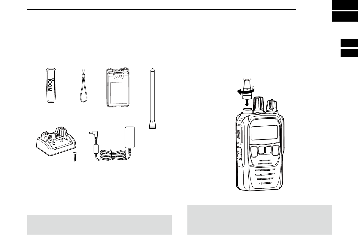
■ Supplied accessories
Belt clip
Battery charger
(With a screw)
NOTE: Some accessories are not supplied, or the shape is
different, depending on the transceiver version.
Handstrap
Power adapter
(For Battery charger)
Battery pack
Antenna
■ Attaching accessories
D Flexible antenna
Connect the supplied exible antenna to the antenna
connector.
CAUTION:
• DO NOT carry the transceiver by holding only the antenna.
• DO NOT connect an antenna other than those listed in
this instruction manual.
1
2
3
4
5
6
7
8
9
10
11
12
13
14
15
16
2
Page 8
2
ACCESSORIES
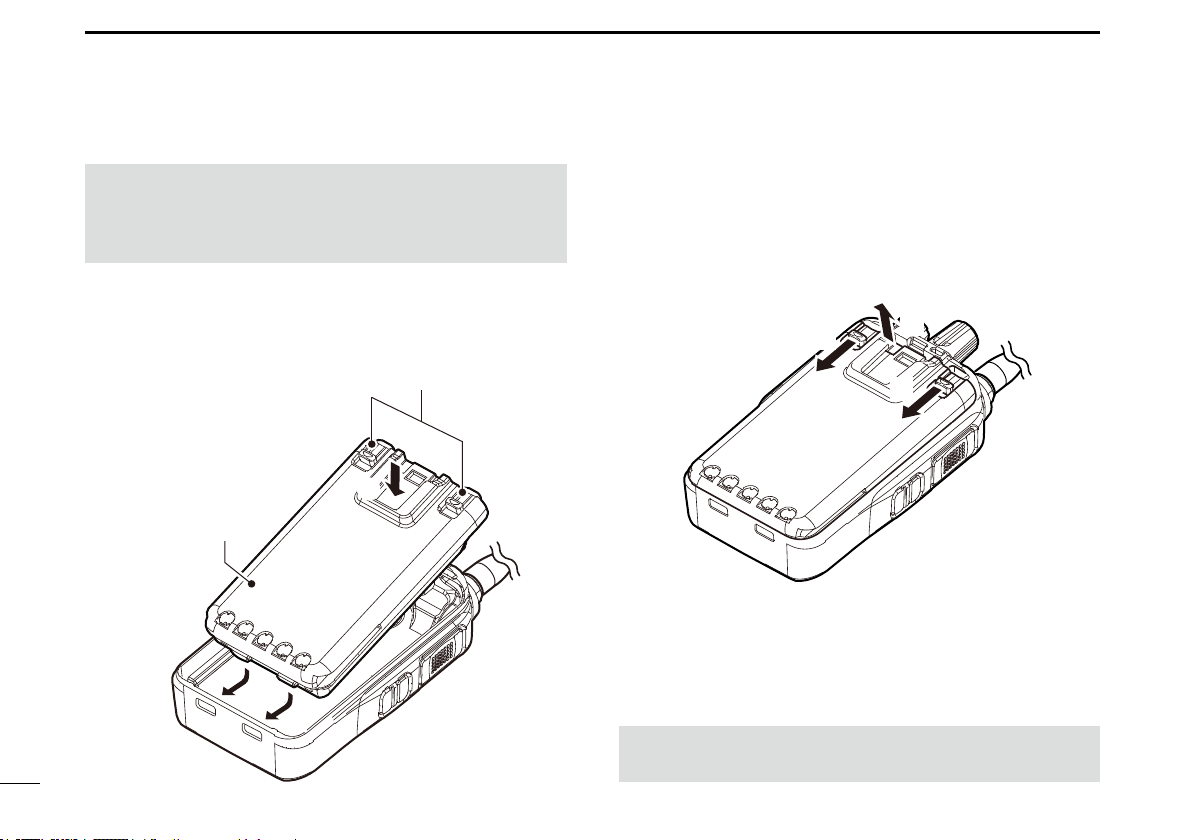
D Battery pack
CAUTION: DO NOT attach or detach the battery pack
when the transceiver is wet or soiled. This may result in
water or dust getting into the transceiver/ battery pack and
may damage the transceiver.
To attach:
1. Slide the battery pack in the direction of the arrow. (q)
2. Push the battery pack until the battery sliding locks
make a ‘click’ sound. (w)
Battery sliding locks
w
Battery pack
q
q
3
To detach:
1. Pull both battery sliding locks in the direction of the
arrow. (z)
2. Lift up to detach the battery pack. (x)
z
NOTE: Keep the battery pack terminals clean. It’s a good
idea to occasionally clean them.
x
z
Page 9
ACCESSORIES
2
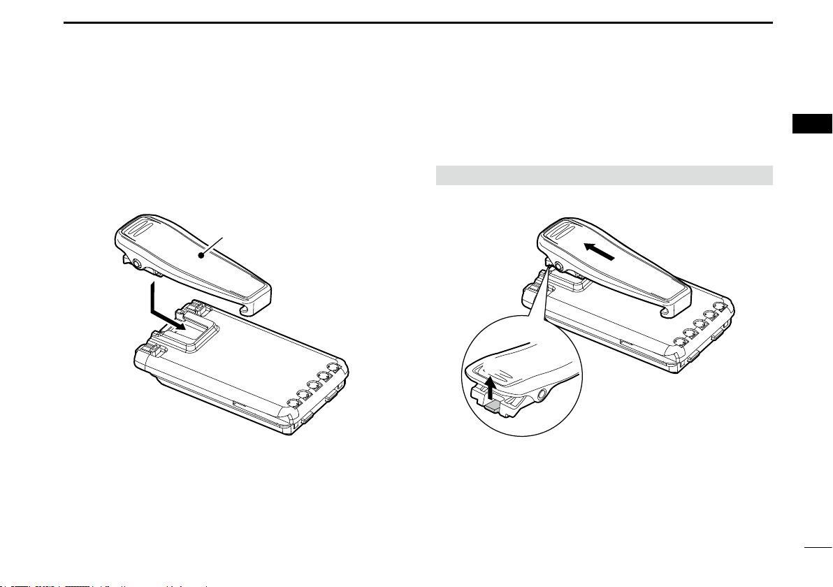
D Belt clip
To attach:
1. Remove the battery pack from the transceiver, if it is
attached.
2. Slide the belt clip in the direction of the arrow until the
belt clip is locked and makes a ‘click’ sound.
Belt clip
To detach:
Lift the tab up (q), and slide the belt clip in the direction of
the arrow (w).
BE CAREFUL! DO NOT break your ngernail.
w
q
1
2
3
4
5
6
7
8
9
10
11
12
13
14
15
16
4
Page 10
3
PANEL DESCRIPTION
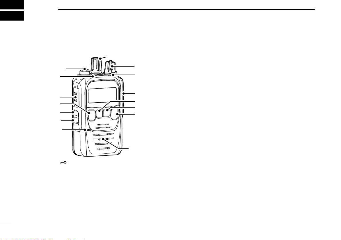
■ Front, top and side panels
!2
Antenna
Connector
q
w
e
r
t
Microphone
q LOCK KEY [ ]
Hold down for 1 second to lock or unlock the keypad.
L Push to use the pre-assigned function. Ask dealer for details.
w PTT SWITCH [PTT]
Hold down to transmit, release to receive.
e CHANNEL 16/CALL CHANNEL KEY [16/C] (p. 11)
z Push to select Channel 16.
z Hold down for 1 second to select the Call channel.
r SQUELCH ADJUSTMENT KEY [SQL] (p. 14)
z Push to enter or exit the Squelch Adjustment mode.
5
z Hold down to open the squelch, to monitor the channel.
!1
!0
o
i
u
y
Speaker
t TRANSMIT POWER KEY [H/L]
z Push to set the power level to high, mid, or low.
L Some channels are set to only low power.
z Hold down for 1 second to display the battery health
and battery cycle. (p. 18)
y FAVORITE CHANNEL KEY [FAV] (p. 16)
z Push to select a Favorite channel.
z Hold down for 1 second to set or clear the selected
channel as a Favorite channel.
u SCAN/DUALWATCH KEY [SCAN]/[DUAL]
z Push to start or stop a scan. (p. 15)
z Hold down for 1 second to start the Dualwatch.* (p. 17)
L While Dualwatch, push to cancel Dualwatch.
*Tri-watch may start, depending on the Set mode settings.
i WEATHER CHANNEL*/ CHANNEL GROUP KEY
[CH/WX]/[U/I/C/L]/[CH]
z Push to enter or exit the Weather Channel Selection
mode.* (p. 12)
*Except the European, UK, and German versions.
z Hold down for 1 second to change the channel group. (p. 12)
o MULTI-CONNECTOR
Connects to an optional speaker microphone or headset.
!0 STATUS INDICATOR
z Lights red while transmitting.
z Lights green while receiving a signal, or when the
squelch is open.
!1 VOLUME/POWER SWITCH [VOL]
z Rotate to turn the transceiver ON or OFF.
z Rotate to adjust the audio output level.
!2 TUNING DIAL [DIAL]
z Rotate to select a channel.
Page 11
PANEL DESCRIPTION
3
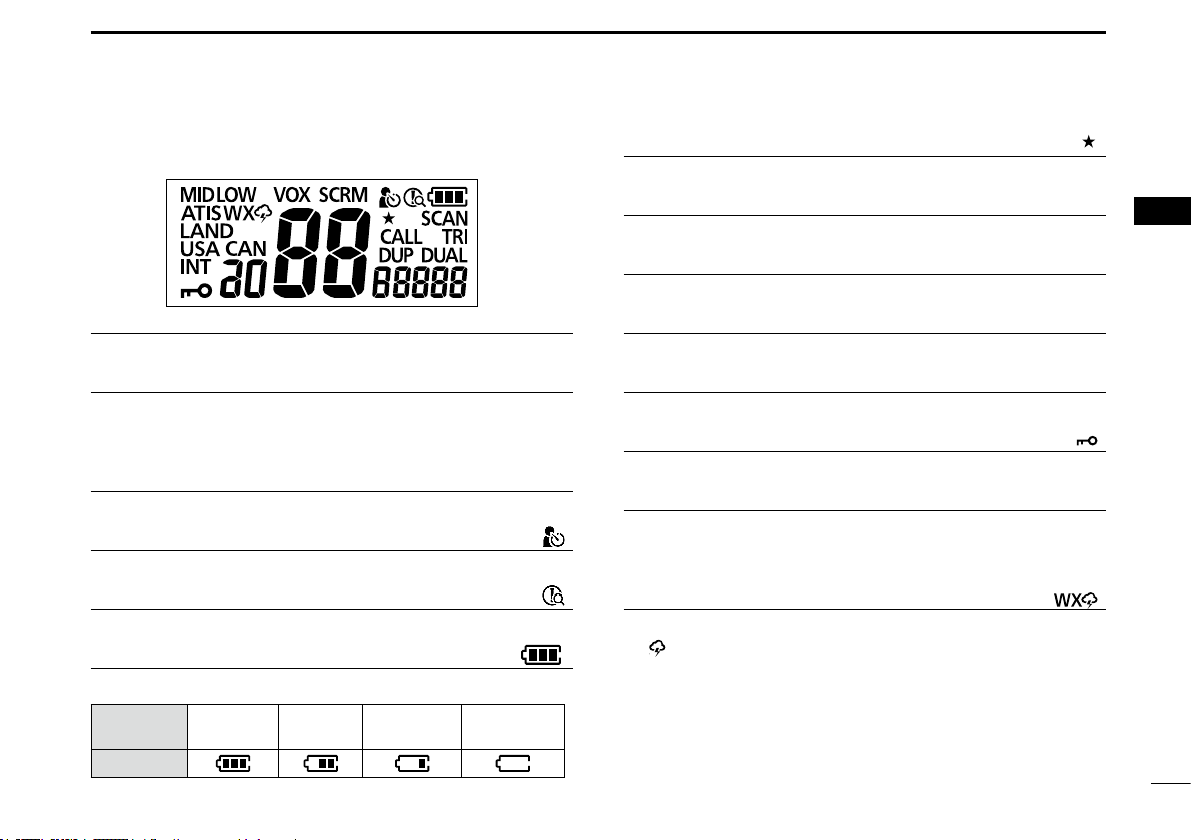
■ Function display
TRANSMIT POWER INDICATOR “MID”/“LOW”
Displayed when low power or mid power is selected.
VOX INDICATOR “VOX”
Displayed when the VOX function* is ON.
* Usable only when the optional PTT switch cable and headset are
connected.
VOICE SCRAMBLER INDICATOR “SCRM”
Displayed when the Voice scrambler is ON. (p. 18)
MAN DOWN ICON
Displayed when the Man Down Alarm function is ON. (p. 22)
LONE WORKER ICON
Displayed when the Lone Worker Alarm function is ON. (p. 22)
BATTERY INDICATOR
Displays the battery status.
Battery
status
Indication
Full Mid
Charging
required
exhausted
“ ”
“ ”
“ ”
Battery
FAVORITE CHANNEL ICON
Displayed when a Favorite channel is selected. (p. 16)
SCAN INDICATOR “SCAN”
Blinks while scanning. (p. 15)
CALL CHANNEL INDICATOR “CALL”
Displayed when the Call channel is selected. (p. 11)
DUALWATCH/TRI-WATCH INDICATOR “DUAL”/“TRI”
Displayed during Dualwatch or Tri-watch operation. (p. 17)
DUPLEX INDICATOR “DUP”
Displayed when a Duplex channel is selected.
LOCK ICON “ ”
Displayed when the Lock function is ON.
CHANNEL GROUP INDICATOR “INT”/“USA”/“CAN”/“LAND”/“ATIS”
Displays the selected channel group.*1 (p. 12)
*1 The selectable channel groups may differ, depending on the
version.
2
WEATHER CHANNEL ICON*
Displayed when the Weather channel is selected. (p. 12)
L “ ” is displayed when the Weather Alert function is ON.
*2 Except the European, UK, and German versions.
“ ”
“ ”
1
2
3
4
5
6
7
8
9
10
11
12
13
14
15
16
6
Page 12

4
BATTERY CHARGING
■ Battery caution
Misuse of Li-ion batteries may result in the following
hazards: smoke, re, or the battery may rupture. Misuse
can also cause damage to the battery or degradation of
battery performance.
R DANGER! NEVER solder the battery terminals, or NEVER
modify the battery pack. This may cause heat generation, and
the battery may burst, emit smoke or catch re.
R DANGER! NEVER place or leave battery packs in areas
with temperatures above 60°C (140°F). High temperature
buildup in the battery cells, such as could occur near res or
stoves, inside a sun-heated vehicle, or in direct sunlight for
long periods of time may cause the battery cells to rupture
or catch re. Excessive temperatures may also degrade the
battery pack’s performance or shorten the battery cell’s life.
R DANGER! NEVER strike or otherwise impact the battery
pack. Do not use the battery pack if it has been severely
impacted or dropped, or if the pack has been subjected to
heavy pressure. Battery pack damage may not be visible
on the outside of the case. Even if the surface of the battery
does not show cracks or any other damage, the cells inside
the battery may rupture or catch re.
R DANGER! NEVER expose the battery pack to rain, snow,
seawater, or any other liquids. Do not charge or use a wet
pack. If the pack gets wet, be sure to wipe it dry before using.
R DANGER! NEVER place or leave battery packs near re.
Fire or heat may cause them to rupture or explode. Dispose
of used battery packs in accordance with local regulations.
R DANGER! NEVER let uid from inside the battery get in
your eyes. This can cause blindness. Rinse your eyes with
clean water, without rubbing them, and immediately go to a
doctor.
R WARNING! NEVER put the battery pack in a microwave
oven, high-pressure container, or in an induction heating
cooker. This could cause a re, overheating, or cause the
battery cells to rupture.
R WARNING! NEVER use the battery pack if it emits an
abnormal odor, heats up, or is discolored or deformed. If
any of these conditions occur, contact your Icom dealer or
distributor.
R WARNING! NEVER Iet uid from inside the battery cells
come in contact with your body. If it does, immediately wash
with clean water.
CAUTION: DO NOT use the battery pack out of the
specied temperature range for the transceiver (–30°C
~ +60°C (–22°F ~ +140°F)) and the battery itself (–20°C
~ +60°C (–4°F ~ +140°F)). Using the battery out of its
specied temperature range will reduce its performance and
battery cell’s life. Please note that the specied temperature
range of the battery may exceed that of the transceiver. In
such cases, the transceiver may not work properly because
it is out of its operating temperature range.
7
Page 13

BATTERY CHARGING
4
CAUTION: DO NOT leave the pack fully charged,
completely discharged, or in an excessive temperature
environment (above 50°C, 122°F) for an extended period of
time. If the battery pack must be left unused for a long time,
it must be detached from the transceiver after discharging.
You may use the battery pack until the remaining capacity is
about half, then keep it safely in a cool and dry place at the
following temperature range:
–20°C ~ +50°C (–4°F ~ +122°F) (within a month)
–20°C ~ +40°C (–4°F ~ +104°F) (within three months)
–20°C ~ +20°C (–4°F ~ +68°F) (within a year)
BE SURE to replace the battery pack with a new one
approximately ve years after manufacturing, even if it still
holds a charge. The material inside the battery cells will
become weak after a period of time, even with little use.
The estimated number of times you can charge the pack
is between 300 and 500. Even when the pack appears to
be fully charged, the operating time of the transceiver may
become short when:
• Approximately 5 years have passed since the pack was
manufactured.
• The pack has been repeatedly charged.
■ Charging caution
R DANGER! NEVER charge the battery pack in areas with
extremely high temperatures, such as near res or stoves,
inside a sun-heated vehicle, or in direct sunlight. In such
environments, the safety/protection circuit in the battery will
activate, causing the battery to stop charging.
R WARNING! NEVER charge the transceiver during a
lightning storm. It may result in an electric shock, cause a
re or damage the transceiver. Always disconnect the power
adapter before a storm.
R WARNING! NEVER charge or leave the battery in the
battery charger beyond the specied time for charging. If the
battery is not completely charged by the specied time, stop
charging and remove the battery from the battery charger.
Continuing to charge the battery beyond the specied time
limit may cause a re, overheating, or the battery may
rupture.
R WARNING! NEVER insert the transceiver (battery
attached to the transceiver) into the charger if it is wet or
soiled. This could corrode the battery charger terminals or
damage the charger. The charger is not waterproof.
CAUTION: DO NOT charge the battery outside of the
specied temperature range: BC-227 (15˚C ~ 40˚C
(59˚F ~ 104˚F)). Otherwise, the charging time will be longer,
but the battery will not reach a full charge. While charging,
at a point after the temperature goes out of the specied
range, the charging will automatically stop.
1
2
3
4
5
6
7
8
9
10
11
12
13
14
15
16
8
Page 14

4
BATTERY CHARGING
■ Battery charger
D Supplied battery charger
Charging time: approximately 2.7 hours
Battery pack
Power adapter*
Status indicator
* May not be supplied, or the shape may be different, depending on
the transceiver version.
9
Turn OFF
Battery charger
D Optional BC-226 desktop charger
Charging time: approximately 2.7 hours
Battery pack
Turn OFF
Power
adapter*
BC-226
Status
indicator
L To connect the power adapter to the charger, remove the
charger’s left cover.
Page 15

BATTERY CHARGING
4
Connecting BC-226 together
You can connect up to 6 BC-226 together.
1. Remove the charger’s right cover. (q)
2. Snap the DC power plug to the other charger’s DC
power jack. (w)
WARNING: DO NOT connect more than 6 chargers
together. It may result in an electric shock, cause a re,
overheating, or damage chargers.
NOTE:
• The transceiver MUST be turned OFF while charging.
Otherwise:
- The battery will not be charged correctly.
- The battery life may be shortened.
• Do not transmit while charging. When you need to
transmit, remove the transceiver from the charger, and
then turn ON the power.
• If the battery pack does not properly charge when it is
attached to the transceiver, remove it from the transceiver
and insert only the battery pack into the charger.
D Information
Status indicator
Light color Status
Orange Charging
Green Charging is completed.
Blinks orange and green Charging failed. It may have some
problems.
BC-226 Fuse replacement
If a fuse blows, nd and repair the cause of the problem.
Then replace the damaged fuse with a new, adequately
rated fuse.
Fuse type: 5 A/58 V (low prole mini blade fuse)
NOTE: Remove the fuse using the needle-nose pliers.
Fuse
1
2
3
4
5
6
7
8
9
10
11
12
13
14
15
16
10
Page 16

5
BASIC OPERATION
■ Selecting a channel
D Channel 16
Channel 16 is the distress and safety channel. It is used for
establishing initial contact with a station, and for emergency
communications.
While standing by, you must monitor Channel 16.
z Push [16/C] to select
Channel 16.
D Call channel
Each Channel Group has separate Call channels. The Call
channel is monitored during Tri-watch. The Call channels
can be selected and used to store your most often used
channel in each Channel Group, for quick recall.
z Hold down [16/C] for 1
second to select the Call
channel.
• The Call channel number and
“CALL” are displayed.
L To return to the previously
selected channel, push [CH/WX]*1 or [CH]*2.
*1 For the USA, Chinese, and Export versions.
*2 For the European, UK, German, and Australian versions.
Setting the Call channel
By default, a Call channel is set in each Channel Group.
You can set your most often-used channel as your Call
channel in each Channel Group for a quick recall.
1. Hold down [16/C] for 1 second to select the Call
channel.
• “CALL” and Call channel number is displayed.
2. Hold down [16/C] again
for 3 seconds (until a
long beep changes to
2 short beeps) .
• The Call channel number
blinks.
3. Rotate [DIAL] to select
the channel.
4. Push [16/C] to set the selected channel as the Call
channel.
• The Call channel number stops blinking.
11
Page 17

BASIC OPERATION
5
D Changing channel group
Channel Groups are preset into your transceiver. You can
select the Channel Group between USA, International,
Canadian, and ATIS depending on the transceiver version.
z Hold down [U/I/C/L]*
channel group.
*1 For the USA, Chinese, and Export versions.
*2 For the European, UK, German, and Australian versions.
Version
USA
UK
European
German
Australian
Export (Other)
Chinese
1
or [CH]*2 for 1 second to change the
Preset Channel Group
USA INT CAN ATIS
D Weather channels
(Except the European, UK, and German versions.)
The transceiver has 10 preset Weather channels. You can
use these channels to monitor broadcasts from the National
Oceanographic and Atmospheric Administration (NOAA).
The transceiver automatically detects a Weather Alert tone
on the selected Weather channel, or while scanning.
1. Push [CH/WX] or [CH]*
selection mode.
*3 For the Australian version.
2. Rotate [DIAL] to select a Weather channel.
Setting the Weather Alert
1. Turn OFF the transceiver.
2. While holding down [SQL], Turn ON the transceiver to
enter the Set mode.
3. Push [SQL] to select the Weather Alert item.
• “ ” is displayed.
4. Rotate [DIAL] to turn
ON the Weather Alert.
• “ ” is displayed.
5. Push [16/C] to exit the Set
mode.
Weather channel list
Channel Frequency (MHz) Channel Frequency (MHz)
1 162.550 6 162.500
2 162.400 7 162.525
3 162.475 8 161.650
4 162.425 9 161.775
5 162.450 10 163.275
3
to enter the Weather channel
1
2
3
4
5
6
7
8
9
10
11
12
13
14
15
16
12
Page 18

5
BASIC OPERATION
13
■ Receiving and transmitting
CAUTION: Transmitting without an antenna will damage the
transceiver.
NOTE: Before using the transceiver for the rst time, the battery
pack must be fully charged for optimum life and operation. See
Section 4 for battery charging.
1. Rotate [DIAL] to select a channel.
• When a signal is received, the status indicator lights green.
2. Hold down [PTT], and speak into the microphone to
transmit.
• The status indicator lights red while transmitting.
3. Release [PTT] to receive.
TIP: To maximize the readability of your transmitted signal, pause
for a second after pushing [PTT] and hold the microphone 5 to 10
cm (2 to 4 inches) from your mouth, and then speak at your normal
voice level.
NOTE:
• To conserve battery power, the Power Save function automatically
turns ON when no signal is received for 5 seconds.
• The Time-out Timer function cuts OFF transmission after 5
minutes* of continuously transmitting, to prevent prolonged
transmission.
* 10 seconds before transmission is cut off, a beep sounds to
indicate the transmission will be cut off, and “TOT” blinks. After
it is cut OFF, “TOT” is displayed for 10 seconds, and you cannot
transmit until it disappears.
* 3 minutes for the Australian version.
1. Select a channel.
2. Push to transmit.
3. Release to receive.
■ Entering the ATIS code
(For the German versions)
The Automatic Transmitter Identication System (ATIS) ID
consists of 10 digits. You can enter the ID as shown below.
NOTE: You can enter this initial code ONLY ONCE. After entry,
only your dealer or distributor can change it. If your ATIS code has
already been entered, this entry is not necessary.
1. Turn OFF the transceiver.
2. While holding down [16/C], turn ON the transceiver.
• Enters the ATIS Code Entry mode, and the cursor blinks.
L The ATIS code is displayed, if it has already been entered.
3. Enter a 10 digit ATIS code.
L Rotate [DIAL] to select the number.
L Push [SCAN] to move the cursor to the right.
L Push [CH] to move the cursor to the left.
4. After entering the 10th digit, push [FAV] to set the ID.
5. Push [16/C] to exit the
ATIS Code Entry mode.
Page 19

BASIC OPERATION
5
■ Adjusting the squelch level
The squelch enables the audio to be heard only while
receiving a signal that is stronger than the set level. A higher
level blocks weak signals, so that you can receive only
stronger signals. A lower level enables you to hear weak
signals.
1. Push [SQL] to enter the
Squelch Adjustment
mode.
2. Rotate [DIAL] to adjust the squelch level, until the noise
just disappears.
3. Push [16/C] to exit the Squelch Adjustment mode.
■ Using the VOX function
NOTE: The optional PTT switch cable and headset are required to
use the function.
The VOX function automatically switches between receive
and transmit by detecting your voice.
z While holding down [SQL], push [CH/WX]*
turn ON or OFF the function.
• “VOX” is displayed.
*1 For the USA, Chinese, and Export versions.
*2 For the European, UK, German, and Australian versions.
1
or [CH]*2 to
■ Using the AquaQuake water
draining function
Water in the speaker grill may mufe the sound coming
from the speaker. The AquaQuake Water Draining function
removes water from the speaker grill by vibrating the
speaker cone.
L The AquaQuake Water Draining function is not usable
when using an optional battery case or the optional speaker
microphone.
1. While holding down [H/L], push [FAV] to turn ON the
function.
• “ ” is displayed.
• A low frequency vibration beep sounds for 10 seconds to
drain the water, regardless of the volume level setting.
2. Push any key to turn OFF the function.
TIP: When the AquaQuake Action setting is ON in the Set mode,
you can use the function by just shaking the transceiver within 30
seconds, after the water is detected (p. 22)
1
2
3
4
5
6
7
8
9
10
11
12
13
14
15
16
14
Page 20

6
SCAN
■ Scan types
You can nd ongoing calls by scanning the Favorite channels.
Before starting a scan, you need to:
• Set the channels that you want to scan as Favorite
channels.
L Only the Favorite channels are scanned.
• Turn ON the Priority Scan in the Set mode to use the
Priority Scan (p. 20).
NORMAL SCAN
The Normal Scan sequentially searches through all
Favorite channels. However, Channel 16 is not checked
unless it is set as a Favorite channel.
CH 01 CH 02
WX*
CH 05 CH 04
CH 03
PRIORITY SCAN
A Priority scan sequentially scans all Favorite channels
while monitoring Channel 16.
CH 01
WX*
CH 05 CH 04
When a signal is received:
• On Channel 16
The scan pauses until the signal on Channel 16 disappears.
• On a channel other than Channel 16:
The scan switches to Dualwatch, until the signal disappears.
* Except the European, UK, and German versions, when the
Weather Alert function is ON, the previously selected Weather
channel is also scanned.
CH 16
CH 02
CH 03
15
Page 21

SCAN OPERATION
6
■ Favorite channels
You can quickly recall often-used channels by setting them
as Favorite channels.
D Setting/Clearing
1. Rotate [DIAL] to select a channel.
2. Push [FAV] to set or clear the channel as a Favorite
channel.
• “ ” is displayed, when the channel is set as a Favorite
channel.
D Selecting
z Push [FAV].
L Non-Favorite channels are skipped and not displayed.
TIP: You can clear all Favorite channels.
L If there are no favorite channel, all channels will be set as
favorite channels.
1. Turn OFF the transceiver.
2. While holding down [FAV], turn ON the transceiver.
Example: Starting a Normal Scan
■ Starting a scan
1. Push [SCAN] to start a scan.
• During a Normal scan, “SCAN” blinks.
• During a Priority scan, “ ” is also displayed.
L When a signal is received, the scan pauses until the signal
disappears, or resumes after pausing for 5 seconds,
depending on the Set mode setting (p. 20).
L Rotate [DIAL] to change the scanning direction.
2. Push [SCAN] again to cancel the scan.
TIP: In order to properly receive signals, be sure to adjust
the squelch to a suitable level.
1
2
3
4
5
6
7
8
9
10
11
12
13
14
15
16
Push [SCAN]. “ SCAN” is displayed while
scanning.
Status indicator lights green
when a signal is received.
16
Page 22

7
Dualwatch Tri-watch
DUALWATCH/TRI-WATCH
■ Description
Dualwatch and Tri-watch are convenient to monitor Channel
16 while you are operating on another channel.
CH 88
CH 16
Monitors Channel 16
while listening on
another channel
(example: CH 88).
When a signal is received:
• On Channel 16
Dualwatch or Tri-watch pauses on Channel 16 until the
signal disappears.
• On the Call channel
Tri-watch switches to Dualwatch until the signal on the
Call channel disappears.
CH 88
Call
channel
CH 9
Monitors Channel 16 and
the Call channel while
listening on another
channel (example: CH 88).
CH 16
■ Operation
1.
Select Dualwatch or Tri-watch in the Set mode (p. 20).
2. Select a channel.
3. Hold down [DUAL] for 1 second to start Dualwatch or
Tri-watch.
• During Dualwatch, “DUAL 16” blinks.
• During Tri-watch, “TRI 16” blinks.
L A beep tone sounds when a signal is received on Channel 16.
L Tri-watch becomes Dualwatch while receiving a signal on the
call channel.
4. Push [DUAL] again to cancel Dualwatch or Tri-watch.
Example: Operating Dualwatch on Channel 07.
Push [DUAL].
Dualwatch resumes after
the signal disappears.
Dualwatch starts.
When a signal is received on
the Channel 16.
17
Page 23

OTHER FUNCTIONS
8
■ Using the LAND channel group
A maximum of 100 programmable channels (allocated
136.000 to 174.000 MHz) are preset into the LAND channel
group for simple communication with LMR/PMR transceivers
in the VHF band.
The default setting of the LAND channel group is the same
as that of the INT channel group. Ask your local Icom
dealer for the LAND channel group setting and LMR/PMR
frequency setting details.
D Selecting the LAND channel group
z Hold down [U/I/C/L]*1 or [CH]*2 for 1 second to change the
channel group.
• “ LAND” is displayed when the LAND channel group is
selected.
*1 For the USA, Chinese, and Export versions.
*2 For the European, UK, German, and Australian versions.
■ Using the Voice Scrambler
The Voice Scrambler provides private communications. In
order to receive or send scrambled transmissions, you must
activate the scrambler function. You also need to set the
scrambler code in the Set mode (p. 21).
L The Voice Scrambler is not usable on Channel 16.
z While holding down [SQL], push [SCAN/DUAL] to turn ON
or OFF the function.
• “SCRM” is displayed.
■ Checking the battery health
and battery cycle
When you using the transceiver with the supplied battery
pack, you can check the battery health and battery cycle.
z Hold down [H/L] for 1 second to the battery cycle.
• Displayed for 5 seconds.
L The battery health is indicated by the status indicator.
Light color Battery health
Blue 80 ~ 100%
Purple 60 ~ 80%
Red 40 ~ 60%
Blinks red 0 ~ 40%
1
2
3
4
5
6
7
8
9
10
11
12
13
14
15
16
18
Page 24

9
SET MODE
■ Using the Set mode
You can set seldom changed settings in the Set mode.
You can customize the transceiver settings to suit your
preference and operating style.
*1
Except the European, UK, and German versions.
*2
The “CH Display” item is displayed for each selectable channel
group.
1. Turn OFF the transceiver.
2. While holding down [SQL], turn ON the transceiver to
enter the Set mode.
• The “Beep” item is displayed.
3. Push [SQL] or [H/L] to select an item.
4. Rotate [DIAL] to select an option.
5. Push [16/C] to exit the Set mode.
19
• Beep • WX Alert*
• Dual/Tri-watch • SQL Key Action • Backlight • Contrast • Power save
• CH Display*
• Man Down Alarm • Lone Worker Alarm • Auto Volume Up • MOB Alarm
2
• Scrambler Code • VOX Level • VOX Delay • AquaQuake Action
1
• Scan Type • Scan Timer • Auto Scan
Page 25

SET MODE
9
■ Set mode items
NOTE: The Set mode items contained in the transceiver
may be different, depending on the transceiver’s version or
presettings. Ask your dealer for details.
D Beep “ ”
Turns the Key Beep function ON or OFF.
• OFF: Turns OFF the function for silent operation.
• ON: When a key is pushed, a beep sounds.
D WX Alert “ ”
(Except the European, UK, and German versions.)
Turns the Weather Alert function ON or OFF.
This function detects the Weather Alert tone on Weather
channels.
• OFF:
The transceiver does not detect a Weather Alert tone.
• ON: The transceiver detects the 1050 Hz Weather Alert
tone on a Weather channel.
D Scan Type “ ”
Turns the Priority Scan function ON or OFF.
• OFF: The scan type is set to “Normal,” which sequentially
searches all Favorite channels in the channel group.
• ON: The scan type is set to “Priority,” which sequentially
searches all Favorite channels in the channel group,
while also periodically checking Channel 16 (Priority
channel).
D Scan Timer “ ”
Turns the Scan Resume Timer ON or OFF.
• OFF: When a signal is detected on a channel, the scan
pauses until the signal disappears, and then
resumes.
• ON: When a signal is detected on a channel, the
scan pauses for 5 seconds, and then resumes. If
the signal disappears in less than 5 seconds, the
scan immediately resumes.
D Auto Scan “ ”
Turns the Automatic Scan function ON or OFF.
• OFF: The function is OFF.
• ON: Scan automatically starts when no signal is
received, or no operations are carried out for 30
seconds.
D Dual/Tri-watch “ ”
Selects the watch type.
• d- (Dual): The watch type is set to Dualwatch, which
monitors Channel 16, even while receiving a
signal on another channel.
• t- (Tri): The watch type is set to Tri-watch, which
monitors Channel 16 and the Call channel, even
while receiving a signal on another channel.
1
2
3
4
5
6
7
8
9
10
11
12
13
14
15
16
20
Page 26

9
SET MODE
21
■ Set mode items (Continued)
D SQL Key Action “ ”
The function temporarily opens the squelch.
• Pu (Push): The Monitor function is activated by holding
down [SQL] for more than 1 second.
• Ho (Hold): The Monitor function is activated by holding
The squelch stays open until the user pushes
The squelch opens while holding down the key.
down [SQL] for more than 1 second.
any key.
D Backlight “ ”
Turns the Automatic Backlight function ON or OFF.
• OFF: The function is OFF.
• ON: The backlight turns ON for 5 seconds when the user
pushes any key except [PTT].
D Contrast “ ”
Selects the transceiver's display contrast.
• Hi: The transceiver's display contrast is set to High.
• Lo: The transceiver's display contrast is set to Low.
D Power Save “ ”
Turns the Power Save function ON or OFF.
• OFF: The function is OFF.
• ON: The Power Save function reduces current drain by
deactivating the receiver circuit of the transceiver at
specic intervals.
D CH Display “ ”/“ ”/“ ”/“ ”
Selects the number of digits to display the channel number.
You can select settings for each channel group.
• 3d: The channel number is displayed in 3 digits.
(Example: 78A)
• 4d: The channel number is displayed in 4 digits.
(Example: 1078)
D Scrambler Code “ ”
Set the voice scrambler code to between 1 and 32.
D VOX Level “ ”
Sets the VOX gain level to between 1 (The lowest
sensitivity) to 10 (The highest sensitivity).
Higher values make the VOX function more sensitive to your
voice.
D VOX Delay “ ”
Sets the VOX Delay to between 1 (The shortest) to 6 (The
longest) in 0.5 second steps.*
*Example: If the VOX delay is set to 2, transmitter stays ON for 1
second.
The VOX Delay is the amount of time the transmitter stays
ON after you stop speaking before the VOX switches to
receive.
Page 27

SET MODE
9
D AquaQuake Action “ ”
(Not displayed when using an optional battery case.)
Selects whether or not to activate the AquaQuake water
draining function by shaking the transceiver.
L This function is not usable when using an optional battery case.
• OFF: While holding down [H/L], push [FAV] to turn ON
the function.
• ON: You can use the function by just shaking the
transceiver within 30 seconds, after the water is
detected.
D Man Down Alarm “ ”
Sets the emergency mode detection angle to between 45,
60, or 75 degrees for the Man Down Alarm function.
If the transceiver leans past the set angle for the preset
period of time, an alarm sounds.*
L Push [PTT] to stop the alarm.
* An alarm sounds from the transceiver’s speaker, even if an
optional speaker microphone is connected.
D Lone Worker Alarm “ ”
Turns the Lone Worker Alarm ON or OFF.
If no operation occurs for the preset period of time, an alarm
sounds.*
L Push [PTT] to stop the alarm.
* An alarm sounds from the transceiver’s speaker, even if an
optional speaker microphone is connected.
• OFF: The function is OFF.
• ON: If no operation occurs during a specied period
of time, the transceiver automatically enter the
Emergency mode.
D Auto Volume Up “ ”
Turns the Auto Volume Up function ON or OFF.
• OFF: The function is OFF.
• ON: The volume level is automatically increased when
a signal is received in a noisy environment while
the ship is pitching or rolling.
D MOB Alarm “ ”
(Not displayed when using an optional battery case.)
Turns the MOB Alarm function ON or OFF.
This function is used when you fallen into the water and
needs to be rescued.
L This function is not usable when using an optional battery case.
* An alarm sounds from the transceiver’s speaker, even if an
optional speaker microphone is connected.
• OFF: The function is OFF.
• ON:
An alarm sounds while the transceiver is in the water.
1
2
3
4
5
6
7
8
9
10
11
12
13
14
15
16
22
Page 28

10
SPECIFICATIONS AND OPTIONS
■ Specications
All stated specications are subject to change without notice
or obligation.
IC-M85 (USA, Export):
D General
• Frequency coverage:
Marine TX 156.025 ~ 157.425 MHz
RX 156.050 ~ 163.275 MHz
LMR 136.000 ~ 174.000 MHz
• Mode:
Marine 16K0G3E
LMR 16K0F3E (Wide)/11K0F3E (Narrow)
• Channel spacing:
Marine ±25 kHz
LMR
• Current drain (at 7.2 V DC): TX High (5 W) 1.5 A typical
Maximum audio 450 mA typical
• Frequency stability: ±5.0 ppm
• Operating temperature range:
Marine –20˚C ~ +60˚C, –4˚F ~ +140˚F
LMR –30˚C ~ +60˚C, –22˚F ~ +140˚F
• Dimensions (projections not included):
2.2 (W) × 3.6 (H) × 1.1 (D) inches
• Weight (approximately): 215 g, 7.6 oz with BP-290
• Antenna impedance: 50 ˘ nominal
±25 kHz (Wide), ±12.5 kHz (Narrow)
56 (W) × 92 (H) × 29 (D) mm,
D Transmitter
• Output power:
Marine 5 W (Hi), 3 W (Mid), and 1 W (Low)
LMR (USA) 2 W (Hi), 1 W (Low)
LMR (Export/Chinese)
• Modulation system :
• Maximum frequency deviation:
Marine ±5 kHz
LMR ±5 kHz (Wide), ±2.5 kHz (Narrow)
• Audio harmonic distortion: Less than 10% (at 60% deviation)
• Spurious emissions: Less than –70 dBc typical
5 W (Hi), 3 W (Mid), and 1 W (Low)
Variable reactance frequency modulation
D Receiver
• Receive system: Double conversion superheterodyne
• Sensitivity (at 12 dB SINAD): 0.25 μV (typical)
• Squelch sensitivity (Threshold):
• Intermodulation rejection ratio:
• Sprious response rejection ratio:
• Adjacent channel selectivity: 70 dB (typical)
55 dB (typical) (Narrow, LMR only)
• Ham and Noise ratio: 40 dB
34 dB (Narrow, LMR only)
• Audio output power: 0.7 W typical at 10% distortion into a
0.35 μV (typical)
70 dB (typical)
70 dB (typical)
12 ˘ load
23
Page 29

SPECIFICATIONS AND OPTIONS
10
IC-M85E (European, UK, German, Australian):
D General
• Frequency coverage:
Marine TX
RX
TX (Australian)
RX (Australian)
PMR 136.000 ~ 174.000 MHz
• Mode:
Marine 16K0G3E
PMR 16K0F3E (Wide)/8K50F3E (Narrow)
PMR (German) 14K0F3E (Wide)/8K50F3E (Narrow)
• Channel spacing:
Marine ±25 kHz
PMR
PMR (German) ±20 kHz (Wide)
• Current drain (at 7.2 V DC): TX High (5 W) 1.5 A typical
Maximum audio 450 mA typical
• Frequency stability:
European/UK/German ±1.5 kHz
Australian ±5.0 ppm (Marine), ±1.5 kHz (PMR)
• Operating temperature range:
Marine –15˚C ~ +55˚C
PMR –25˚C ~ +55˚C
Marine (Australian) –10˚C ~ +55˚C
PMR (Australian) –10˚C ~ +50˚C
• Dimensions (projections not included):
• Weight (approximately): 215 g with BP-290
• Antenna impedance: 50 ˘ nominal
±25 kHz (Wide), ±12.5 kHz (Narrow)
56 (W) × 92 (H) × 29 (D) mm
156.000 ~ 161.450 MHz
156.000 ~ 163.425 MHz
156.025 ~ 157.425 MHz
156.300 ~ 162.025 MHz
, ±12.5 kHz (Narrow)
D Transmitter
• Output power: 5 W (Hi), 3 W (Mid), and 1 W (Low)
• Modulation system :
• Maximum frequency deviation:
Marine ±5 kHz
PMR ±5 kHz (Wide), ±2.5 kHz (Narrow)
PMR (German) ±4 kHz (Wide), ±2.5 kHz (Narrow)
• Audio harmonic distortion: Less than 10% (at 60% deviation)
• Spurious emissions:
European/UK/German 0.25 μW (below 2 GHz)
1 μW (above 2 GHz)
Australian Less than –70 dBc typical
Variable reactance frequency modulation
D Receiver
• Receive system: Double conversion superheterodyne
• Sensitivity (at 20 dB SINAD): –4 dBμ EMF (Wide, Typical)
–2 dBμ EMF
(Narrow, Typical, PMR only)
• Squelch sensitivity (Threshold):
• Intermodulation rejection ratio:
European/UK/German 68 dB (Marine), 65 dB (PMR)
Australian 65 dB
• Sprious response rejection ratio:
European/UK/German 70 dB
Australian 65 dB (Marine), 70 dB (PMR)
• Adjacent channel selectivity:
European/UK/German 70 dB, 60 dB (Narrow, PMR only)
Australian (Marine) 65 dB
Australian (PMR) 70 dB (Wide), 60 dB (Narrow)
• Ham and Noise ratio: 40 dB
34 dB (Narrow, PMR only)
• Audio output power: 0.7 W typical at 10% distortion into a
–6 dBμ EMF (typical)
12 ˘ load (at 1 kHz)
1
2
3
4
5
6
7
8
9
10
11
12
13
14
15
16
24
Page 30

10
SPECIFICATIONS AND OPTIONS
25
■ Options
D Battery pack/Battery case
• BP-290 li-ion battery pack
Voltage: 7.2 V
Capacity: 1910 mAh (minimum), 2010 mAh (typical)
Battery life: Approximately 14 hours*
* When the Power Save function is ON and the operating periods
are calculated under the following conditions:
TX : RX : standby = 5 : 5 : 90
• BP-291 battery case
Battery case for AA alkaline batteries.
D Chargers
• BC-227 rapid charger
+ Bc-123s ac adapter, opc-515L dc power cable
To rapidly charge the battery pack.
Charging time: Approximately 2.7 hours with BP-290
L OPC-515L dc power cable must be purchased separately.
• BC-226 desktop charger + BC-228 ac adapter
You can connect up to 6 BC-226 together.
Charging time: Approximately 2.7 hours with BP-290
A power adapter may be supplied, depending on the charger’s
version.
• BC-214 multi-charger
+ BC-157S ac adapter, opc-656 dc power cable
For rapidly charging of up to 6 battery packs simultaneously.
Charging time: Approximately 2.8 hours
A power adapter may be supplied, depending on the charger’s
version.
L The AD-132N charger adapter may be needed, depending
on the charger's version.
L OPC-656 dc power cable must be purchased separately.
D Others
• FA-SC58V antenna
• MB-136, MBB-3 belt clip
• MB-96F, MB-96FL, MB-96N belt hangers
• CP-23L cigarette lighter cable
Used when charging a battery pack through a 12 V cigarette
lighter socket.
• HM-222 speaker microphone
With a [H/L] key and Earphone jack.
The HM-222 meets IP68 requirements for waterproof protection.
• HM-236 speaker microphone
• HM-163MC tiepin type microphone
+ EH-15B earphone, SP-26 tube earphone, SP-28 ear hook
type earphone
• SP-32 tube type earphone adapter
For use with EH-15B.
• SP-27 tube earphone, SP-29 ear hook type earphone
+ AD-135 earphone adapter
AD-135: Used To connect an earphone to the transceiver’s multi-
connector.
• AD-118 acc adapter
To connect an accessory. See the AD-118 instruction sheet for
details on recommended accessories.
• LC-187, LC-188* carrying case
*Remove the LC-188 from the transceiver before charging.
• VS-5MC ptt switch cable
+ HS-94, HS-95, HS-97 headset
VS-5MC: Used to connect a headset to a transceiver.
HS-94: Ear-hook type
HS-95: Neck-arm type
HS-97: Throat microphone
Some options may not be available in some countries.
Ask your dealer for details.
Page 31

SPECIFICATIONS AND OPTIONS
10
■ Using the HM-222
[H/L]
Microphone
Speaker
[PTT]
Turn OFF the
Earphone jack
NOTE:
• NEVER immerse the connector in water. If the connector
becomes wet, BE SURE to dry it before attaching to the
transceiver.
• The microphone element is located at the top left of the
speaker microphone, as shown in the illustration above.
To maximize the readability of your transmitted audio,
hold the microphone approximately 5 to 10 cm (2 to 4
inches) from your mouth, and then speak at your normal
voice level.
transceiver
before attaching
or detaching the
microphone
Belt clip
You can connect
an earphone (user
supplied) to the
earphone jack on
the microphone.
To attach:
Attach the connector of the speaker microphone to
the multi connector on the transceiver and tighten the
screw.
Turn OFF
Screw
Coin
CAUTION: Firmly attach to the multi
connector, but do not overtighten.
A loose connection will allow water
intrusion into the connector. Overtightening the connection can
damage the transceiver.
1
2
3
4
5
6
7
8
9
10
11
12
13
14
15
16
26
Page 32

10
q
w
w
q
SPECIFICATIONS AND OPTIONS
■ Using the BP-291
When using the optional BP-291
battery case, install 5 × AA (LR6) size
Alkaline batteries.
1. Open the battery case, and then
remove the battery holder.
w
q
2. Install Alkaline batteries to the
battery holder, and then insert it to
the battery case.
3. Firmly close the battery case.
CAUTION:
• NEVER incinerate used battery cells
since internal battery gas may cause
them to rupture.
•
NEVER expose a detached battery case to
water. If the battery case gets wet, be sure
to wipe it dry before using it.
• NEVER use batteries whose insulated
cover is damaged.
NOTE:
• When installing the batteries, make sure
they are all the same brand, type and
capacity. Also, do not mix new and old
batteries together.
• Keep the battery terminals clean. It’s a
good idea to occasionally clean them.
27
Page 33

VHF MARINE CHANNEL LIST
11
Channel number Frequency (MHz)
8
USA*
01A
05A 05A
06 06
07A 07A
08 08
09 09
10 10
11 11
12 12
13*
14 14
15*
16 16
17*
18A 18A
19A 19A
20 20*
CAN*5Transmit Receive
INT
01
5
01A*
02
02
03
03
04
04A
5
05A*
06
07
5
07A*
08
09
10
11
12
1
4
15*
1
17*
18A*
1
13*
13
14
1
3
15*
16
1
2
17*
18
5
19
19A
19b
1
156.050 160.65001
156.050 156.050
156.100 160.700
156.150 160.750
156.200 160.800
156.200 156.200
156.250 160.85005
156.250 156.250
156.300 156.300
156.350 160.950
156.350 156.350
156.400 156.400
156.450 156.450
156.500 156.500
156.550 156.550
156.600 156.600
156.650 156.650
156.700 156.700
156.750
156.750
156.800 156.800
156.850 156.850
156.900 161.500
156.900 156.900
156.950 161.550
156.950 156.950
Rx only 161.550
157.000 161.60020
Channel number Frequency (MHz)
8
USA*
20A
21A 21A
22A 22A
23A
24 24
25 25
26 26
27 27
28 28
37A*
63A 63A 156.175 156.17563A*
CAN*5Transmit Receive
INT
20A
20b
21
5
21A*
21b
22
5
22A*
23
23
5
23A*
23b
6
24*
6
25*
25b
6
26*
27
5
27A*
28
5
28A*
28b
9
9
37A*
60
60
61
61A
62
62A
5
157.000 157.000
Rx only 161.600
157.050 161.650
157.050 157.050
Rx only 161.650
157.100 161.700
157.100 157.100
157.150 161.750
157.150 157.150
Rx only 161.750
157.200 161.800
157.250 161.850
Rx only 161.850
157.300 161.900
157.350 161.950
157.350 157.350
157.400 162.000
157.400 157.400
Rx only 162.000
157.850 157.850
156.025 160.625
156.075 160.675
156.075 156.075
156.125 160.725
156.125 156.125
156.175 160.77563
Channel number Frequency (MHz)
USA*
65A
66A
67*
68
69
71
72
73
74
77*
8
INT
1
1
1
1
CAN*
5
65A*
5
66A*
64
64A
67
68
69
71
72
73
74
75*
76*
77*
5
Transmit
156.225 160.82564
156.225 156.225
156.275 160.87565
1
156.275 156.27565A*
156.325 160.92566
1
156.325 156.32566A*
156.375 156.37567
156.425 156.42568
156.475 156.47569
156.575 156.57571
156.625 156.62572
156.675 156.67573
156.725 156.72574
1
156.775 156.77575*
1
156.825 156.82576*
1
156.875 156.87577
Receive
156.925 161.52578
78A
78A
156.925 156.92578A
Rx only 161.52578b
156.975 161.57579
79A
79A
156.975 156.97579A
Rx only 161.57579b
157.025 161.62580
5
80A
81A 81A 157.075 157.07581A*
80A
157.025 157.02580A*
157.075 161.67581
5
157.125
161.72582
Channel number Frequency (MHz)
8
USA*
82A 82A
83A 83A
84 84
85 85
86 86
87 87
88 88
P4*
*1 Low power only.
2
Low power only for the European,
*
UK, and German versions.
3
Low power only except the
*
Australian version.
4
Rx only.
*
5
For only the USA and Export
*
versions.
6
For only the European, UK, German,
*
and Australian versions.
7
For only the Australian version.
*
8
For only the USA, Export, and
*
Australian versions.
9
UK Marina Channels M1=37A
*
CAN*5Transmit Receive
INT
5
5
83b
6
6
6
7
7
9
9
157.125
157.175
157.175
Rx only
157.225
157.275
157.325
157.375
Rx only
157.425
Rx only
161.425 161.425P4*
157.12582A*
161.77583
157.17583A*
161.775
161.82584*
161.87585*
161.92586*
157.37587
161.97587b*
157.42588
162.02588b*
(157.850 MHz), M2=P4 (161.425
MHz) for only the UK version.
1
2
3
4
5
6
7
8
9
10
11
12
13
14
15
16
NOTE: When the “CH Display” is set to “4d” in the set mode, the channel number is displayed in 4 digits. See page 21 for details.
(For example: Channel 78A is displayed as “1078,” channel 78b” is displayed as “2078.” )
28
Page 34

12
PROBLEM POSSIBLE CAUSE SOLUTION REF.
The transceiver does
not turn ON.
Little or no sound
comes from the
speaker.
You cannot transmit,
or cannot select high
power
.
Scan does not start. • More than 2 favorite channels are not set. • Set the Favorite channels. p. 16
No beep sounds. • The Key Beep function is OFF.
The keypad and [DIAL]
does not work.
TROUBLESHOOTING
• The battery is exhausted.
• The battery pack is not correctly attached.
• Squelch level is set too high.
• Volume level is set too low.
• The speaker has been exposed to water.
• Some channels are set for low power or
receive only by regulations.
• The output power is set to low.
• The keypad and [DIAL] is locked. • Hold down [ ] for 1 second to lock or
• Recharge the battery pack.
• Correctly reattach the battery pack.
• Adjust the squelch level.
• Adjust the volume level.
• Use the AquaQuake Water Draining
function to remove water from the
speaker grill.
• Change channels.
• Push [H/L] to select high power.
• Turn ON the Key Beep function.
unlock the keypad.
p. 9
p. 3
p. 14
p. 5
p. 14
p. 11
p. 5
p. 20
p. 5
29
Page 35

INFORMATION
13
■ About CE and DOC
Hereby, Icom Inc. declares that the
versions of IC-M85E which have the
“CE” symbol on the product, comply with
the essential requirements of the Radio
Equipment Directive, 2014/53/EU, and the
restriction of the use of certain hazardous substances in
electrical and electronic equipment Directive, 2011/65/EU.
The full text of the EU declaration of conformity is available
at the following internet address:
http://www.icom.co.jp/world/support/
■ Disposal
The crossed-out wheeled-bin symbol on your
product, literature, or packaging reminds you
that in the European Union, all electrical and
electronic products, batteries, and accumulators
(rechargeable batteries) must be taken to
designated collection locations at the end of their working
life. Do not dispose of these products as unsorted municipal
waste. Dispose of them according to the laws in your area.
■ Country code list
• ISO 3166-1
Country Codes Country Codes
1 Austria AT 18 Liechtenstein LI
2 Belgium BE 19 Lithuania LT
3 Bulgaria BG 20 Luxembourg LU
4 Croatia HR 21 Malta MT
5 Czech Republic CZ 22 Netherlands NL
6 Cyprus CY 23 Norway NO
7 Denmark DK 24 Poland PL
8 Estonia EE 25 Portugal PT
9 Finland FI 26 Romania RO
10 France FR 27 Slovakia SK
11 Germany DE 28 Slovenia SI
12 Greece GR 29 Spain ES
13 Hungary HU 30 Sweden SE
14 Iceland IS 31 Switzerland CH
15 Ireland IE 32 Turkey TR
16 Italy IT 33 United Kingdom GB
17 Latvia LV
1
2
3
4
5
6
7
8
9
12
13
14
15
16
30
Page 36

INFORMATION
13
31
■ Firmware version identication
You can identify your transceiver’s rmware version.
1. Turn OFF the transceiver.
2. While holding down [
• The rmware version is displayed.
L Example: “ ” is displayed, when the firmware is
Version 1.001.
], turn ON the transceiver.
■ FCC information
This equipment has been tested and found to comply with
the limits for a Class A digital device, pursuant to part 15
of the FCC Rules. These limits are designed to provide
reasonable protection against harmful interference when the
equipment is operated in a commercial environment. This
equipment generates, uses, and can radiate radio frequency
energy and, if not installed and used in accordance with the
instruction manual, may cause harmful interference to radio
communications. Operation of this equipment in a residential
area is likely to cause harmful interference in which case the
user will be required to correct the interference at his own
expense.
CAUTION: Changes or modications to this transceiver,
not expressly approved by Icom Inc., could void
your authority to operate this transceiver under FCC
regulations.
■ Information FCC
Cet équipement a été testé et reconnu conforme aux
limites xées pour un appareil numérique de classe A,
conformément au point 15 de la réglementation FCC.
Ces limites sont dénies de façon à fournir une protection
raisonnable contre le brouillage préjudiciable lorsque cet
appareil est utilisé dans un environnement commercial. Cet
équipement génère, utilise et peut émettre un rayonnement
de fréquence radio. S'il n'a pas été installé conformément
aux instructions, il peut par ailleurs créer des interférences
perturbant les communications radio. L'utilisation de cet
appareil dans une zone résidentielle peut provoquer un
brouillage préjudiciable, auquel cas l'utilisateur sera tenu de
corriger la situation à ses frais.
MISE EN GARDE: Tout changement ou modication,
non expressément approuvé par Icom Inc., peut annuler
l'autorisation de l'utilisateur à utiliser cet appareil
conformément à la réglementation FCC.
Page 37

■ Safety training information
CAUTION
Your Icom radio generates RF electromagnetic energy while
transmitting. This radio is designed for and classied as for
“Occupational Use Only.” This means it must be used only
during the course of employment by individuals aware of
WARNING
and complies with the FCC and IC RF exposure limits for “Occupational Use
Only”. In addition, your Icom radio complies with the following Standards and
Guidelines with regard to RF energy and electromagnetic energy levels and
evaluation of such levels for exposure to humans:
• FCC KDB Publication 447498 D03, Evaluating Compliance with FCC
Guidelines for Human Exposure to Radio Frequency Electromagnetic
Fields.
• American National Standards Institute (C95.1-1992), IEEE Standard
for Safety Levels with Respect to Human Exposure to Radio Frequency
Electromagnetic Fields, 3 kHz to 300 GHz.
• American National Standards Institute (C95.3-1992), IEEE Recommended
Practice for the Measurement of Potentially Hazardous Electromagnetic
Fields– RF and Microwave.
• The accessories listed on page i are authorized for use with this product.
Use of accessories other than those specied may result in RF exposure
levels exceeding the FCC requirements for wireless RF exposure.
• Health Canada Safety Code 6 - Limits of Human Exposure to
Electromagnetic Energy in the Frequency Range from 3 kHz to 300 GHz.
the hazards, and the ways to minimize such hazards. This
radio is NOT intended for use by the “General Population”
in an uncontrolled environment. This radio has been tested
To ensure that your expose to RF electromagnetic energy is
within the FCC allowable limits for occupational use, always
adhere to the following guidelines:
INFORMATION
• DO NOT operate the radio without a proper antenna attached, as this may
damage the radio and may also cause you to exceed FCC RF exposure
limits. A proper antenna is the antenna supplied with this radio by the
manufacturer or an antenna specically authorized by the manufacturer for
use with this radio.
• DO NOT transmit for more than 50% of the total radio use time (“50%
duty cycle”). Transmitting more than 50% of the time can cause FCC
RF exposure compliance requirements to be exceeded. The radio is
transmitting when “TX” is displayed on the function display. You can cause
the radio to transmit by pushing the [PTT] switch.
• ALWAYS keep the antenna at least 2.5 cm (1 inch) away from the body
when transmitting and only use the Icom belt-clips which are listed on page
12 when attaching the radio to your belt, or other place, to ensure FCC and
IC RF exposure compliance requirements are not exceeded.
The information listed above provides the user with the information needed
to make him or her aware of RF exposure, and what to do to assure that this
radio operates within the FCC RF exposure limits of this radio.
Electromagnetic Interference/Compatibility
During transmissions, your Icom radio generates RF energy that can possibly
cause interference with other devices or systems. To avoid such interference,
turn off the radio in areas where signs are posted to do so. DO NOT operate
the transmitter in areas that are sensitive to electromagnetic radiation such as
hospitals and blasting sites.
Occupational/Controlled Use
The radio transmitter is used in situations in which persons are exposed as
consequence of their employment provided those persons are fully aware of
the potential for exposure and can exercise control over their exposure.
13
10
11
12
13
32
Page 38

INFORMATION
A
VERTISSEMENT
MISE EN GARDE
13
33
■ Infomation en matiére de sécurité
Votre radio Icom produit une énergie électromagnétique de
radiofréquences (RF), en mode de transmission. Cette radio
est conçue pour un «usage professionnel seulement» et
classée comme tel, ce qui signie qu’elle doit être utilisée
uniquement dans le cadre d’un travail par des personnes
conscientes des dangers et des mesures visant à minimiser ces dangers.
Elle N’EST PAS conçue pour une «utilisation grand public », dans un
environnement non contrôlé. Cet appareil a été évalué et jugé conforme, aux
limites d’exposition aux RF de la FCC et d’IC, pour une «utilisation grand
public». En outre, votre radio Icom satisfait les normes et directives qui
suivent en matière de niveaux d’énergie et d’énergie électromagnétique de
RF et d’évaluation de tels niveaux en ce qui concerne l’exposition humaine:
• Publication 447498 D03 de la FCC KDB, «Evaluating Compliance with
FCC Guidelines for Human Exposure to Radio Frequency Electromagnetic
Fields».
• Norme de l’American National Standards Institute (ANSI): IEEE C95.1-1992
sur les niveaux de sécurité compatibles avec l’exposition humaine aux
champs électromagnétiques de radiofréquences (3 kHz à 300 GHz).
• Norme de l’ANSI: IEEE C95.3-1992 sur la méthode d’évaluation
recommandée du champ magnétique potentiellement dangereux des
radiofréquences et des micro-ondes.
• Les accessoires illustrés dans “Options” de la feuille d'instructions sont
approuvés pour une utilisation avec ce produit. L’utilisation d’accessoires
autres que ceux précisés peut entraîner des niveaux d’exposition aux RF
supérieures aux limites établies par la FCC et d’IC en matière d’exposition
aux RF sans l.
• Le Code de sécurité 6 de Santé Canada - Les limites d’exposition humaine à
l’énergie électromagnétique dans la gamme de fréquences de 3 kHz à 300 GHz.
An de vous assurer que votre exposition à une énergie
électromagnétique de RF se situe dans les limites permises par
la FCC pour une utilisation grand public, veuillez en tout temps
respecter les directives suivantes :
• NE PAS faire fonctionner la radio sans qu'une antenne appropriée y soit
xée, car ceci risque d'endommager la radio et causer une exposition
supérieure aux limites établies par la FCC. L'antenne appropriée est
celle qui est fournie avec cette radio par le fabricant ou une antenne
spécialement autorisée par le fabricant pour être utilisée avec cette radio.
• NE PAS émettre pendant plus de 50% du temps total d'utilisation de
l'appareil («50% du facteur d'utilisation»). Émettre pendant plus de 50% du
temps total d'utilisation peut causer une exposition aux RF supérieure aux
limites établies par la FCC. La radio est en train d’émettre lorsque le témoin
du “TX” s’afche sur l’écran ACL. La radio émettra si vous appuyez sur le
bouton du microphone.
• TOUJOURS tenir l'antenne éloignée d'au moins 2,5 cm de votre corps
au moment d'émettre et utiliser uniquement l'attache pour ceinture Icom
illustrée à la p. 12, lorsque vous attachez la radio à votre ceinture, ou à
autre chose, de façon à vous assurer de ne pas provoquer une exposition
aux RF supérieure aux limites xées par la FCC. Pour offrir à vos
interlocuteurs la meilleure qualité de transmission possible, tenez l'antenne
à au moins 5 cm de votre bouche et légèrement de côté.
Les renseignements ci-dessus fournissent à l'utilisateur toute l'information
nécessaire sur l'exposition aux RF et sur ce qu'il faut faire pour assurer que cette
radio fonctionne en respectant les limites d'exposition aux RF établies par la FCC.
Interférence électromagnétique et compatibilité
En mode de transmission, votre radio Icom produit de l'énergie de RF qui
peut provoquer des interférences avec d'autres appareils ou systèmes. Pour
éviter de telles interférences, mettez la radio hors tension dans les secteurs
où une signalisation l’exige. NE PAS faire fonctionner l'émetteur dans des
secteurs sensibles au rayonnement électromagnétique tels que les hôpitaux,
les aéronefs et les sites de dynamitage.
Usage professionnel/contrôlé
Ce radio émetteur est utilisé dans des cas où des personnes sont exposées
en raison de leur travail, pourvu qu'elles soient conscientes du risque
d'expositionet qu'elles puissent exercer un contrôle sur cette exposition.
Page 39

INDEX
A
Accessories
Attaching .................................... 2
Supplied ..................................... 2
AquaQuake ................................ 14
ATIS code .................................. 13
B
Backlight .................................... 21
Basic operation .......................... 11
Battery
Battery cycle .............................. 18
Battery health ............................. 18
Caution....................................... 7
Charger ...................................... 9
Charging caution ........................ 8
C
Channel
Selecting .................................... 11
Call channel ............................... 11
Channel group ........................... 12
Channel list ................................ 28
Favorite channels....................... 16
Land channel ............................. 18
Weather channels ...................... 12
D
Dualwatch ...................................... 17
F
Function display............................... 6
L
Lock key .......................................... 5
O
Operating rules ................................ 1
Options ............................................ 25
P
Panel description ............................. 5
R
Receiving ......................................... 13
S
Scan
Normal scan ............................... 15
Priority scan ............................... 15
Set mode
AquaQuake action ..................... 22
Auto scan ................................... 20
Auto volume up .......................... 22
Beep........................................... 20
Channel display ......................... 21
Contrast ..................................... 21
Dual/tri-watch ............................. 20
Lone worker alarm ..................... 22
Man down alarm ........................ 22
MOB alarm ................................. 22
Power save ................................ 21
Scan timer .................................. 20
Scan Type .................................. 20
Scrambler Code ......................... 21
SQL key action ........................... 21
VOX Delay ................................. 21
VOX Level .................................. 21
WX Alert ..................................... 20
Specications .................................. 23
Squelch............................................ 14
T
Transmitting ..................................... 13
Troubleshooting ............................... 29
V
Voice scrambler ............................... 18
VOX function ................................... 14
13
14
15
16
34
Page 40

A7424D-1EX-1
Printed in Japan
© 2017–2018 Icom Inc.
1-1-32 Kamiminami, Hirano-ku, Osaka 547-0003, Japan
 Loading...