

Page 1
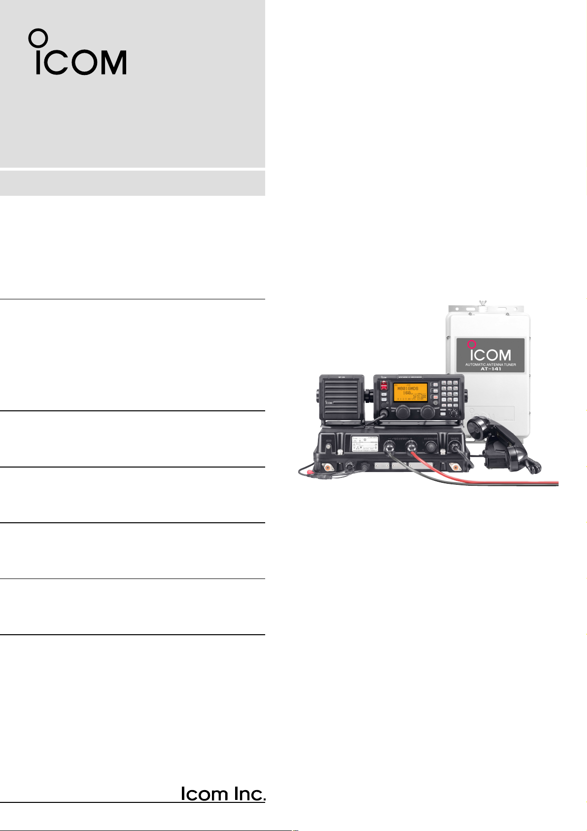
MF/HF MARINE TRANSCEIVER
INSTRUCTION MANUAL
iM801GMDSS
Jun. 2007
for Rev. 1.00
Page 2
i
FOREWORD
Thank you for purchasing this Icom product. The ICM801GMDSS
MF
/
HF MARINE TRANSCEIVER
is designed
and built with Icom’s superior technology and craftsmanship. With proper care, this product should provide
you with years of trouble-free operation.
We want to take a couple of moments of your time to
thank you for making the IC-M801GMDSS your radio of
choice, and hope you agree with Icom’s philosophy of
“technology first.” Many hours of research and development went into the design of your IC-M801GMDSS.
D
FEATURES
❍ Standard 4×8″remote controller
❍
Built-in DSC meets ITU Class A requirement
IMPORTANT
READ THIS INSTRUCTION MANUAL
CAREFULLY before attempting to operate the
transceiver.
SAVE THIS INSTRUCTION MANUAL. This
manual contains important safety and operating instructions for the IC-M801GMDSS.
EXPLICIT DEFINITIONS
R WARNING HIGH VOLTAGE! NEVER at-
tach an antenna or internal antenna connector during
transmission. This may result in an electrical shock or
burn.
R WARNING! NEVER connect the transceiver to
an AC outlet directly. This may pose a fire hazard or
result in an electric shock.
R WARNING! NEVER mount the transceiver
main unit overhead. The weight of the unit is approximately 8.5 kg, but its apparent weight will increase
several fold due to wave shocks or vibration. The unit
must be mounted on a flat hard surface only.
R NEVER connect a power source of more than
31.2 V DC. This connection could cause a fire or ruin
the transceiver.
R NEVER place the transceiver where normal oper-
ation of the ship or vehicle may be hindered or where it
could cause bodily injury.
R NEVER let metal, wire or other objects touch any
internal part or connectors on the rear panel of the
transceiver. This may result in an electric shock.
DO NOT use chemical agents such as benzine or alcohol when cleaning, as they can damage the transceiver surface.
During maritime mobile operation, KEEP the transceiver and handset or microphone as far away as possible
(at least 1 m) from the magnetic navigation com-
pass to prevent erroneous indications.
Use Icom handset or microphones only (supplied or op-
tional)
. Other manufacturer’s handset or microphones
have different pin assignments, and connection to the
IC-M801GMDSS may damage the transceiver.
AVOID using or placing the transceiver in areas with
temperatures below –15°C or above +55°C.
AVOID placing the transceiver in excessively dusty environments or in direct sunlight.
AVOID placing the transceiver against walls or putting
anything on top of the transceiver. This will obstruct
heat dissipation.
Place the unit in a secure place to avoid inadvertent
use by children.
BE CAREFUL! The transceiver main unit will become
hot when operating the transceiver continuously for
long periods.
PRECAUTIONS
WORD DEFINITION
RR
WARNING
Personal injury, fire hazard or electric
shock may occur.
CAUTION Equipment damage may occur.
NOTE
If disregarded, inconvenience only. No
risk or personal injury, fire or electric
shock.
Icom, Icom Inc. and the are registered trademarks of
Icom Incorporated (Japan) in the United States, the United
Kingdom, Germany, France, Spain, Russia and/or other
countries.
IBM is a registered trademark of International Business Machines.
Page 3
ii
When your ship requires assistance, contact other ships and the Coast Guard by sending a distress call using digital selective calling on an emergency frequency.
IN CASE OF EMERGENCY
When immediate help is needed
q Push and hold [DISTRESS] for 5 sec. until the
short beeps become one long beep, to send the
distress call.
w After the appropriate traffic frequency is automati-
cally selected (after an acknowledgement call is
received), push and hold the PTT switch on the
handset or microphone and send the following information.
1. “MAY DAY, MAY DAY, MAY DAY.”
2. “THIS IS……………” (name of ship)
3. “LOCATED AT ……” (ship’s position)
4. Give the reason for the distress call.
5. Explain what assistance you need.
6. Give additional information:
• Ship type
• Ship length
• Ship color
• Number of people on-board
When potential problems exist
q Push [DSC] to select DSC watch mode, if neces-
sary.
w Push [MODE
SET
] to select DSC menu, rotate [CH]
to select “Geographical” then push [ENT].
e Follow the guidance displayed on the LCD (bottom
line), to set up the category, area, calling and traffic frequencies with [CH], [ENT] and keypad.
r Push and hold [CALL] for 1 sec. until the short
beeps become one long beep.
t Transmit the appropriate information using voice.
• DSC equipped ships may monitor your transmission.
1
2
3
4
5
6
7
8
9
10
11
12
13
14
15
16
17
Quick Reference
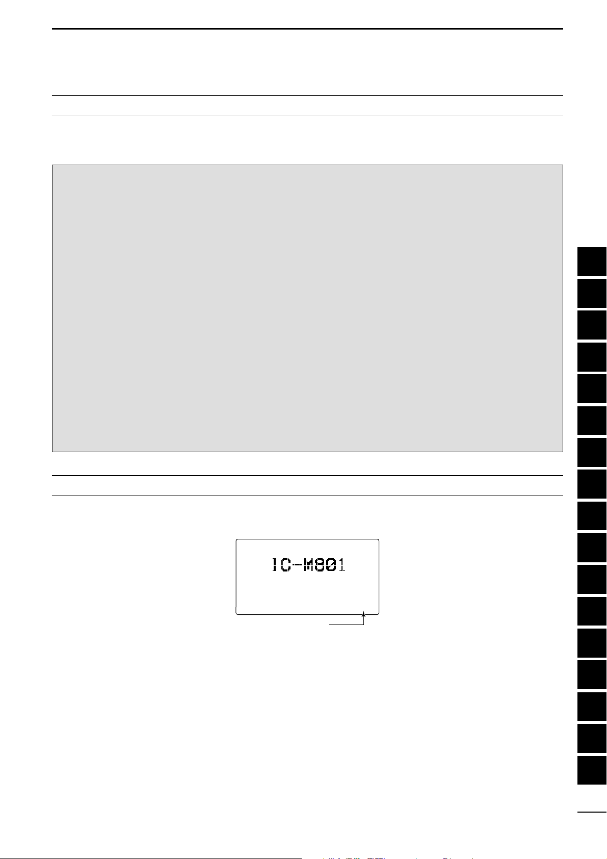
The main firmware revision number is displayed in the opening screen as below.
The revision number is also displayed when MMSI code check screen is selected. (see page 43)
<MMSI>
123456789
1.00
Main firmware revision
number indication
MAIN FIRMWARE REVISION NUMBER
Page 4

TABLE OF CONTENTS
FOREWORD...............................................................i
IMPORTANT ............................................................. i
EXPLICIT DEFINITIONS .......................................... i
PRECAUTIONS ........................................................ i
IN CASE OF EMERGENCY .....................................ii
MAIN FIRMWARE REVISION NUMBER .................ii
TABLE OF CONTENTS .......................................... iii
1 OPERATING RULES AND GUIDELINES ........... 1
2 PANEL DESCRIPTION ................................... 2–7
■ Controller (RC-25GMDSS) .............................. 2
■ Main unit ........................................................... 4
■ Handset (HS-98) .............................................. 5
■ LCD screen ...................................................... 6
3 SELECTING A CHANNEL/FREQUENCY ...... 8–9
■ Selecting a channel .......................................... 8
4 RECEIVE AND TRANSMIT ........................ 10–12
■ Basic voice transmit and receive .................. 10
■ Function for transmit ...................................... 10
■ Functions for receive ...................................... 11
■ FSK operation ................................................ 12
5 CHANNEL NAME PROGRAMMING ................ 13
6 FREQUENCY PROGRAMMING ................ 14–15
■ Frequency selection ....................................... 14
■ Programming a frequency .............................. 15
7 DSC PREPARATION .................................. 16–17
■ MMSI code programming ............................... 16
■ Position and time programming ..................... 17
8 CALL PROCEDURE ................................... 18–27
■ Distress call .................................................... 18
■ Individual call ................................................. 20
■ Group call ....................................................... 22
■ Geographical call ........................................... 24
■ Position request call ....................................... 26
■ Test call .......................................................... 27
9 WHEN RECEIVING A CALL ...................... 28–39
■ To receive a DSC call ..................................... 28
■ Received information ..................................... 29
■ Deleting a memory ......................................... 30
■ Distress call .................................................... 31
■ Distress acknowledgement call ...................... 34
■ Distress relay call ........................................... 35
■ Individual call ................................................. 36
■ Group call ....................................................... 38
■ Polling call ...................................................... 38
■ Position request call ....................................... 39
■ Geographical area call ................................... 39
10 MEMORY OPERATION .................................... 40
■ Memory description ........................................ 40
■ Memory writing ............................................... 40
■ Memory reading/transmitting/deleting ............ 40
11 DSC MENU OPERATION ........................... 41–44
■ General .......................................................... 41
■ ID input ........................................................... 41
■ Frequency input ............................................. 42
■ Verifying self-ID .............................................. 43
■ Self testing ..................................................... 43
■ Scanning distress frequency setting .............. 43
■ Memory reading/deleting ............................... 44
■ Printing out the DSC memory contents .......... 44
12 SET MODE ................................................. 45–49
■ Quick set mode .............................................. 45
■ Initial set mode ............................................... 46
13 CONNECTION AND INSTALLATION ........ 50–63
■ Supplied accessories ..................................... 50
■ Basic connections ...........................................51
■ Advanced connections ................................... 52
■ Ground connection ......................................... 53
■ Power source ................................................. 54
■ Antenna .......................................................... 55
■ Mounting ........................................................ 56
■ Using the optional MB-108 ............................. 58
■ Using the optional MB-75 ............................... 59
■ Transceiver dimensions ................................. 60
■ Fuse replacement .......................................... 61
■ Connector information .................................... 62
14 SPECIFICATIONS ............................................ 64
15 OPTIONS .......................................................... 65
16 TEMPLATE ................................................. 67–70
■ Remote controller (RC-25GMDSS) ................ 67
■ Speaker (SP-24E) .......................................... 69
17 ANTENNA AND GROUNDING
CONSIDERATIONS ................................... 71–73
iii
Page 5

1
1
OPERATING RULES AND GUIDELINES
1
Quick Reference
Before transmitting, monitor the channel you wish to
use so as to avoid interrupting transmissions already in progress.
• CALL PROCEDURE
Calls must be properly identified and the time limit
must be respected.
q Give your call sign each time you call another ship
or coast guard station. If you have no call sign,
identify the station by giving your ship name and the
name of the licensee.
w Give your call sign at the end of each transmission
that lasts more than 3 min.
e You must break and give your call sign at least once
every 15 min. during long ship-to-shore calls.
r Keep your unanswered calls short, less than
30 sec. Do not repeat a call for 2 min.
t Unnecessary transmissions are not allowed.
• PRIORITIES
q Read all rules and regulations pertaining to priori-
ties and keep an up-to-date copy handy. Safety and
distress calls take priority over all others.
w False or fraudulent distress signals are prohibited
and punishable by law.
• PRIVACY
q Information overheard but not intended for you, can-
not lawfully be used in any way.
w Indecent or profane language is prohibited.
• LOGS
q All distress, emergency and safety calls must be
recorded in complete details. Log data activity is
usually recorded in 24 hour time. Universal Time
Coordinated (UTC) is frequently used.
w Adjustments, repairs, channel frequency changes
and authorized modifications affecting electrical operation of the equipment must be kept in the maintenance log; entries must be signed by the authorized licensed technician performing or supervising
the work.
• RADIO LICENSES
(1) SHIP STATION LICENSE
You must have a current radio station license before
using the transceiver. It is unlawful to operate a ship
station which is not licensed.
Inquire through your dealer or the appropriate government agency for a Ship-Radiotelephone license application. This government-issued license states the call
sign which is your craft’s identification for radio purposes.
(2) OPERATOR’S LICENSE
A Restricted Radiotelephone Operator Permit is the license most often held by small ship radio operators
when a radio is not required for safety purposes.
The Restricted Radiotelephone Operator Permit must
be posted or kept with the operator. Only a licensed
radio operator may operate the transceiver.
However, non-licensed individuals may talk over a
transceiver if a licensed operator starts, supervises,
and ends the call and makes the necessary log entries.
Keep a copy of the current government rules and regulation handy.
Page 6
2
2
PANEL DESCRIPTION
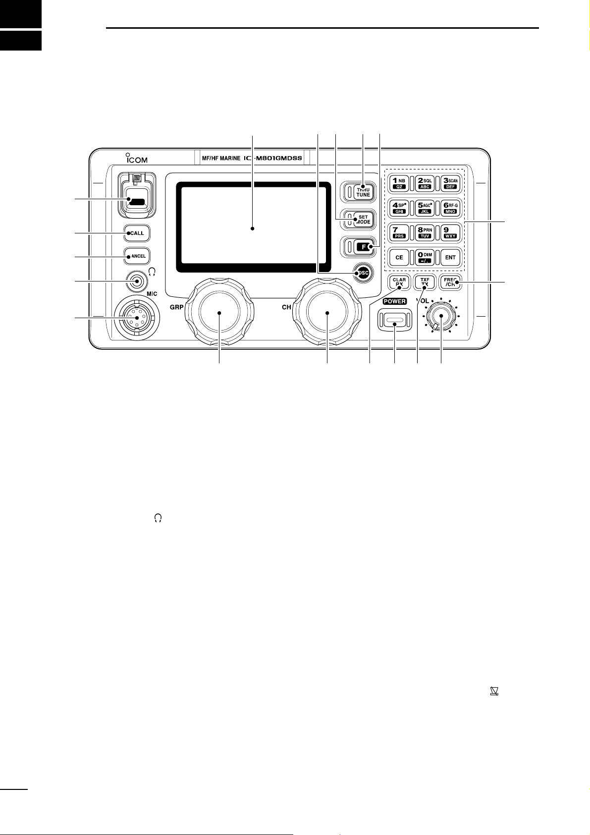
■ Controller (RC-25GMDSS)
q DISTRESS SWITCH [DISTRESS] (p. 18)
Push and hold for 5 sec. (approx.) to make a distress call.
w CALL SWITCH [CALL]
Push and hold for 1 sec. to start calling after DSC
contents are setup.
e CANCEL SWITCH [CANCEL]
Cancels a distress or DSC repeat call.
r HEADPHONE JACK [ ]
Accepts headphones.
• Output power: 2.5 mW with a 16 Ω load
(stereo/monaural)
t MICROPHONE CONNECTOR [MIC]
Accepts the supplied or optional microphone.
• See p. 65 for appropriate microphones.
• See p. 62 for microphone connector information.
y GROUP SELECTOR [GRP]
➥
Selects groups in 20 channel steps and ITU marine channel groups.
(p. 8)
➥ Selects items during quick/initial set mode, etc.
u CHANNEL SELECTOR [CH]
➥ Selects an operating channel within the selected
channel group such as ITU channels. (p. 8)
•User channels can be selected from 1 to 160 (max.)
in sequence regardless of the channel group.
➥ Changes setting or value of the selected item
during quick/initial set mode, etc.
i RX/CLARITY SWITCH [RX
CLAR
]
➥ After pushing [F], turns the clarity function ON
and OFF. (p. 12)
• [CH] is used for clarity control.
➥ During DSC watch mode, enters Received Call
Log screen. (p. 29)
• [CH] is used for distress and other call selection.
o POWER SWITCH [POWER]
➥ Push to turn the power ON.
➥ Push and hold for 1 sec. to turn the power OFF.
!0 TX/TRANSMIT FREQUENCY SWITCH [TX
TXF
]
➥
After pushing [F], displays the transmit frequency, and opens the squelch. Checks and monitors the transmit frequency while holding. (p. 10)
➥ During DSC watch mode, enters TX memory se-
lect screen. (p. 40)
• [CH] is used for memory selection.
!1 VOLUME CONTROL [VOL]
Adjusts the audio output level.
• Audio does not come from the speaker when:
- The speaker OFF switch is turned ON.
- The squelch function is turned ON and no signal is
being received.
-Pick the handset up with speaker switch “ ” position.
(p. 5)
- During DSC watch mode.
DISTRESS
q
w
e
r
t
yuio!0 !1
!2
!3
!4!5!6!7Function display (pgs. 6, 7)
Page 7
3
2
PANEL DESCRIPTION
2
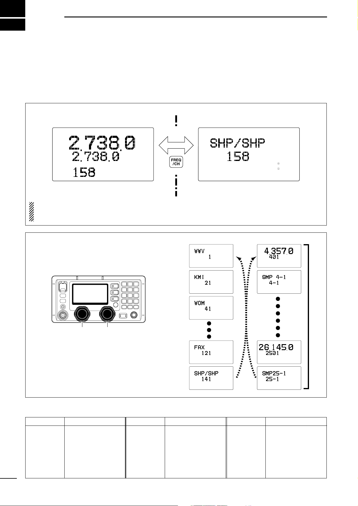
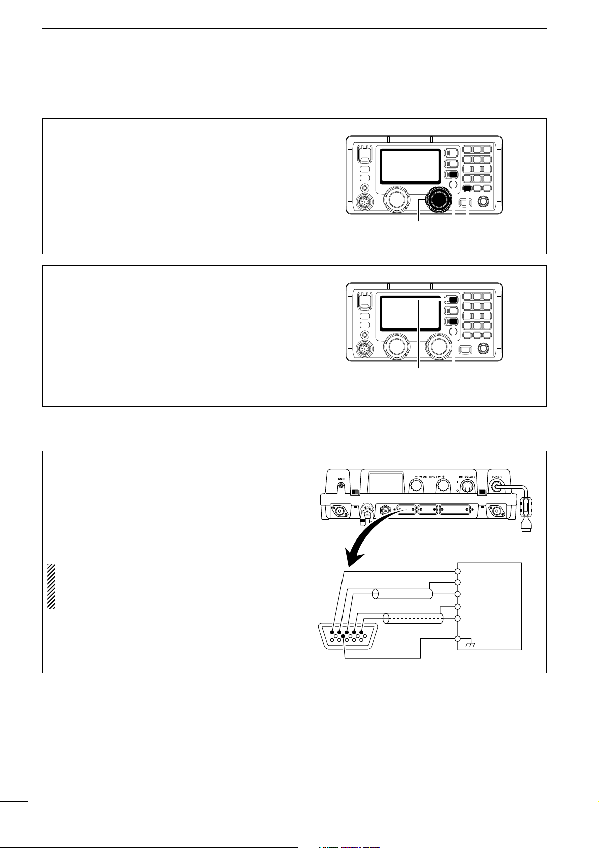
!2 FREQUENCY/CHANNEL SWITCH [FREQ/CH]
➥ Selects indication type: (p. 8)
When channel comment indication is ON;
switches channel comment indication ON and
OFF.
When channel comment indication is OFF;
switches transmit frequency indication ON and
OFF.
➥ After pushing [F], enters channel name pro-
gramming mode, when channel comment indication is ON. (p. 13)
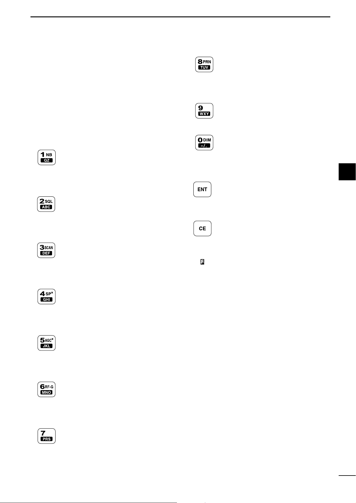
!3 KEYPAD
➥ Inputs numeral “1” for channel number
input, etc.
➥ Inputs “1,” “Q,” “Z,” “q,” “z” or space for
channel comment input.
➥ After pushing [F], turns the noise
blanker function ON and OFF. (p. 11)
➥ Inputs numeral “2” for channel number
input, etc.
➥ Inputs “2,” “A,” “B,” “C,” “a,” “b” or “c” for
channel comment input.
➥ After pushing [F], turns the squelch
function ON and OFF. (p. 11)
➥ Inputs numeral “3” for channel number
input, etc.
➥ Inputs “3,” “D,” “E,” “F,” “d,” “e” or “f” for
channel comment input.
➥ After pushing [F], starts and stops the
scan function. (p. 9)
➥ Inputs numeral “4” for channel number
input, etc.
➥ Inputs “4,” “G,” “H,” “I,” “g,” “h” or “i” for
channel comment input.
➥ After pushing [F], turns the external
speaker output ON and OFF. (p. 10)
➥ Inputs numeral “5” for channel number
input, etc.
➥ Inputs “5,” “J,” “K,” “L,” “j,” “k” or “l” for
channel comment input.
➥ After pushing [F], turns the AGC OFF
function ON and OFF. (p. 11)
➥ Inputs numeral “6” for channel number
input, etc.
➥ Inputs “6,” “M,” “N,” “O,” “m,” “n” or “o” for
channel comment input.
➥ After pushing [F], enters the RF gain ad-
justment mode. (p. 11)
➥ Inputs numeral “7” for channel number
input, etc.
➥ Inputs “7,” “P,” “R,” “S,” “p,” “r” or “s” for
channel comment input.
➥ Inputs numeral “8” for channel number
input, etc.
➥ Inputs “8,” “T,” “U,” “V,” “t,” “u” or “v” for
channel comment input.
➥ After pushing [F], push for 1 sec. to print
out the DSC contents, etc. (p. 44)
➥ Inputs numeral “9” for channel number
input, etc.
➥ Inputs “9,” “W,” “X,” “Y,” “w,” “x” or “y” for
channel comment input.
➥ Inputs numeral “0” for channel number
input, etc.
➥ Inputs “0” and symbols (.,()*+-
/<=>@) for channel comment input.
➥ After pushing [F], selects LCD backlight
brightness.
➥ Fixes input of channel number and chan-
nel comment, etc.
➥ When pushed for 1 sec., stores pro-
grammed frequency, operating mode and
memory comment into a channel.
➥ Clears entered digits and retrieves the
previous frequency, channel or channel
names during setting.
!4 FUNCTION SWITCH [F]
After pushing, activates the secondary functions.
•“ ” appears when a secondary function can be accessed.
!5 TUNE/THROUGH SWITCH [TUNE
THRU
]
➥ Starts tuning the connected AT-141
HF AUTOMATIC
ANTENNA TUNER
.
•“TUNE” appears when tuned.
•When the tuner cannot tune the antenna, the tuning
circuit is bypassed automatically after 15 sec.
➥ After pushing [F], bypasses the connected an-
tenna tuner. (p. 12)
•“THRU” appears instead of “TUNE” indication.
!6 MODE/SET SWITCH [MODE
SET
]
➥ Push to select an operating mode.
•J3E (USB), H3E (AM), LSB, J2B (AFSK), F1B (FSK),
and A1A (CW) modes are available, depending on
version or countries.
➥ After pushing [F], enters quick set mode. (p. 45)
➥ During DSC watch mode, enters DSC menu.
!7 DSC SWITCH [DSC]
Switches DSC watch mode and voice communication mode when pushed.
Page 8
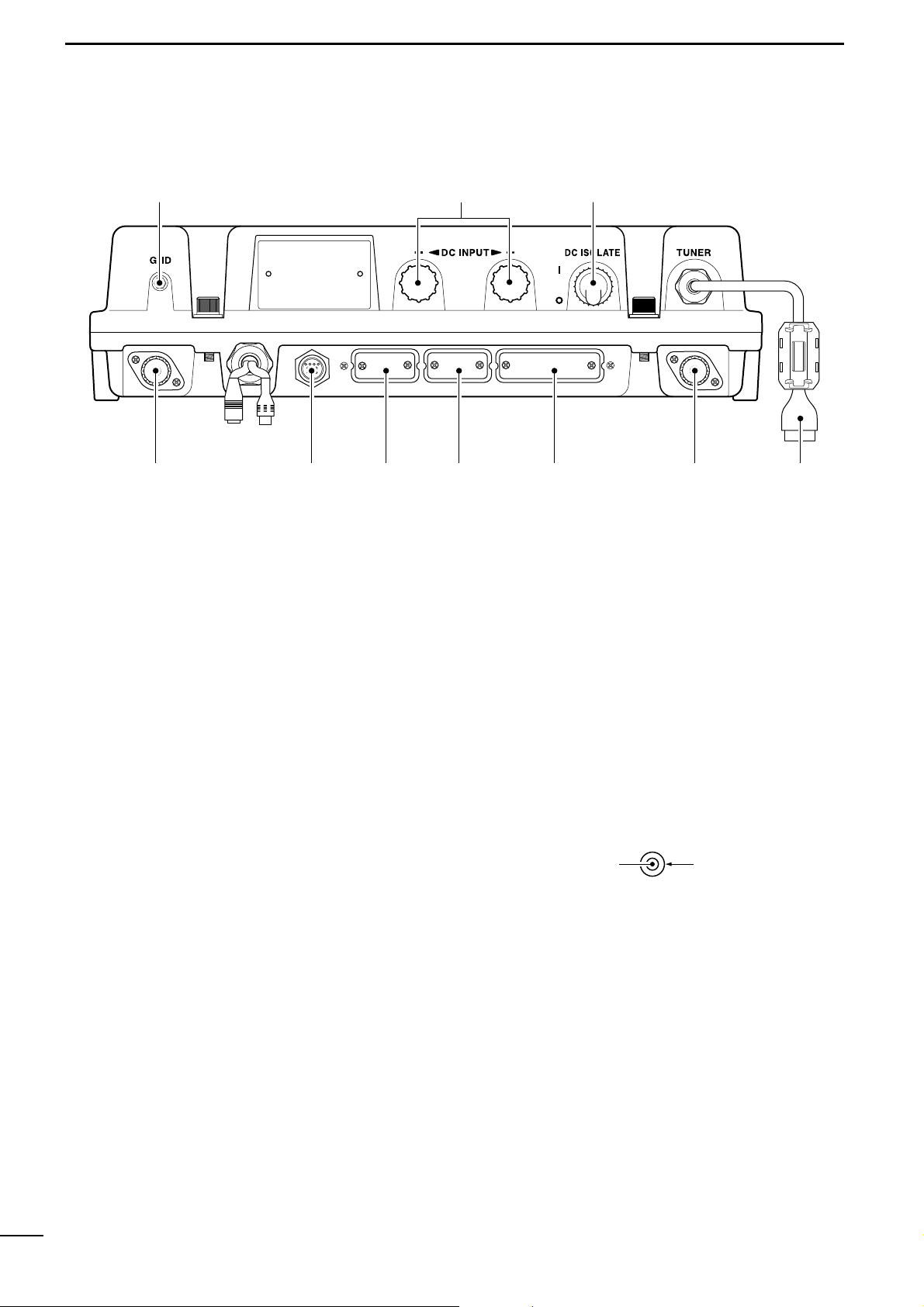
■ Main unit
q
GROUND TERMINAL
IMPORTANT! Connects a ship’s ground. See
page 53 for details.
w DC POWER TERMINALS (pgs. 51, 54)
Accepts 24 V DC through the supplied DC power
cables.
Red terminal is for positive and black terminal is for
negative connection.
e DC ISOLATE SWITCH [DC ISOLATE] (p. 51)
Turns the transceiver’s main power ON and OFF.
r TUNER CONTROL SOCKET (pgs. 51, 55)
Connects a control cable to the antenna tuner, AT-
141.
A female connector kit is supplied for antenna tuner
connection.
t ANTENNA CONNECTOR 1 (pgs. 51, 55)
Connects a 50 Ω HF band antenna via a 50 Ω
matched coaxial cable with a PL-259 plug for both
transmit and receive operation.
y PRINTER CONNECTOR (pgs. 52, 63)
Connects an IBM®centronics or compatible printer
to print out received DSC information automatically
or manually.
u REMOTE CONNECTOR [REMOTE] (p. 63)
Connects a cable (D-sub 9-pin) for remote control
in the IEC61162-1 format.
i MODEM CONNECTOR [AF/MOD] (pgs. 52, 62)
Connects to an NBDP (Narrow Band Direct Printing) or FAX system via a D-sub 15-pin cable.
This connector can also be used as SSB telephony
interface (600 Ω).
o CONTROLLER CONNECTOR [CONTROLLER]
(p. 51)
Connects the supplied remote controller, RC25GMDSS.
!0 GPS CONNECTOR [GPS] (p. 52)
Input position and UTC data (IEC6112-1 format),
such as from a GPS receiver, etc., for setting your
positioning and time data automatically without
manual input for DSC operation.
!1 SPEAKER JACK [SP] (p. 51)
Connects the supplied external speaker, SP-24E.
!2 ANTENNA CONNECTOR 2 (p. 51)
Connects a 50 Ω HF band antenna via a 50 Ω
matched coaxial cable with a PL-259 plug for DSC
receiver.
IMPORTANT!: An HF antenna should be con-
nected to this antenna connector,
otherwise no DSC call can be received.
GPS IN (+)
RCA
GPS IN (–)
4
2
PANEL DESCRIPTION
qwe
rtyuio
!0!1
!2
✔ For detailed “ANTENNA AND GROUNDING CON-
SIDERATIONS,” see pages 71 to 73.
Page 9
5
2
PANEL DESCRIPTION
2
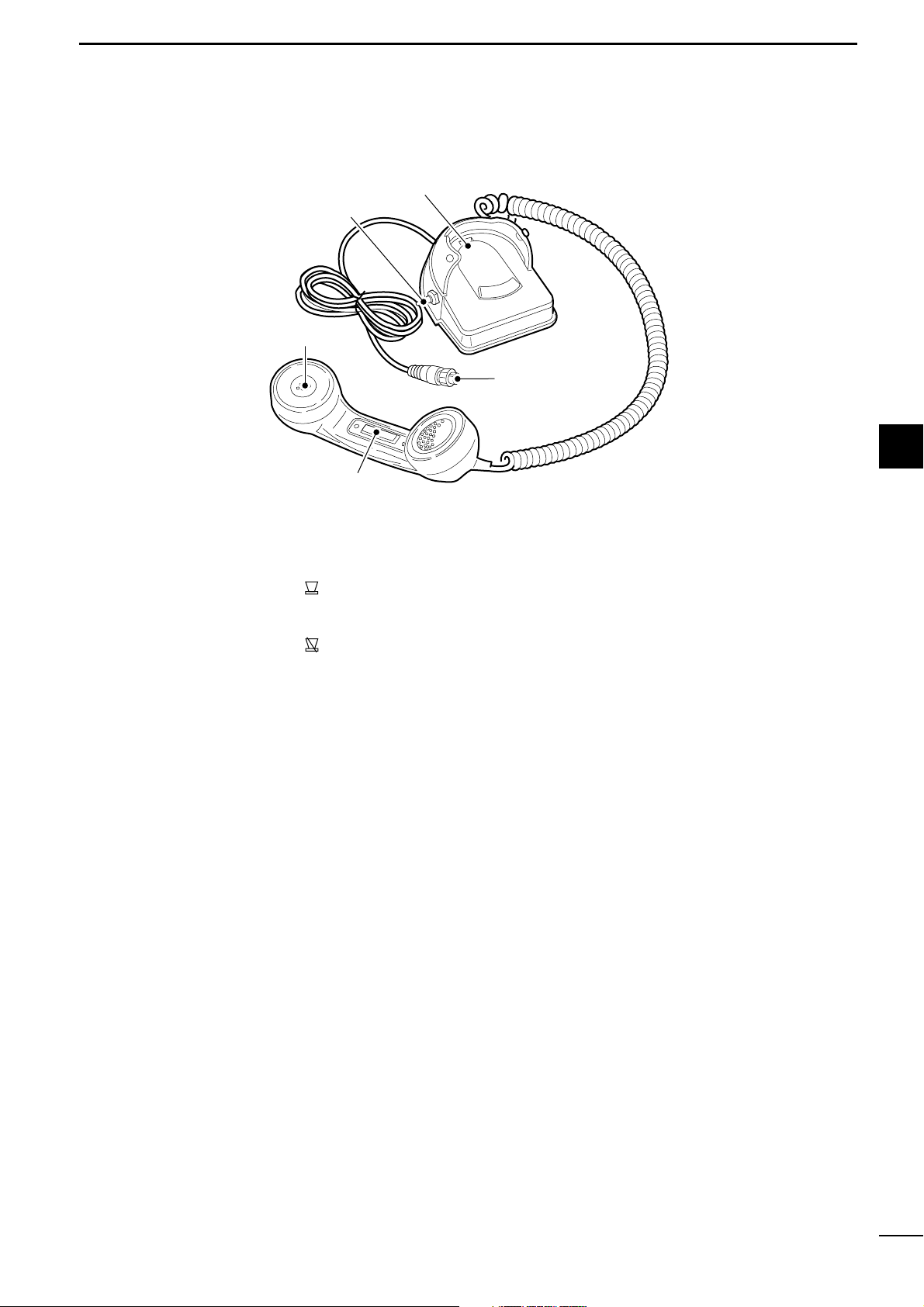
■ Handset (HS-98)
q SPEAKER SWITCH
Toggle the connected external speaker output ON
and OFF when pick the handset up.
• When the switch is set to “ ” position
- Emits the receiving audio from the connected external speaker.
• When the switch is set to “ ” position
- Mutes the connected external speaker output.
•The receiving audio can be heard from the earpiece
of the handset.
- Replace the handset into the cradle to emits the
receiving audio from the connected external
speaker.
w HANDSET CONNECTOR
Connects to [MIC] connector on the remote controller. (p. 51)
e PTT SWITCH [PTT]
Push and hold to transmit; release to receive.
Handset
q
Cradle
w
e
Page 10
6
2
PANEL DESCRIPTION
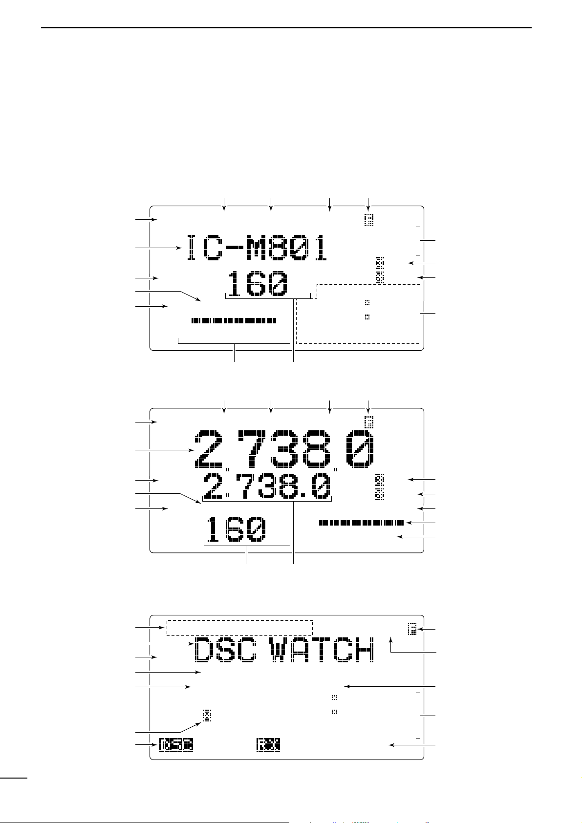
■ LCD screen
The IC-M801GMDSS has 2 indication types, one is
channel name indication and the other is frequency indication. These indication types can be switched with a
push of a button, depending on set mode’s setting.
See pages 8 and 47 for display type settings.
NB SQL
0123
4A
CH
CLAR
0
SP
AGC
---GPS---
Lat
45 59'N
Lon134
44'E
16:23
RX
TX
TX
TUNE J3E
SIMP
Exit
SP
34 34.000N
134
34.000E
12:34
RX
12.345.5
2
4 6 8
12 16
F1B
GPS
Unread MSG
NB SQL
CH
CLAR
0
SP
AGC
UTC
16:23
RX TUNE J3E
SIMP
ACK
MMSI
123456789
• Channel name indication
• Frequency indication
• DSC watch mode indication
q
we rt
y
u
i
o
!0
!1
!2
!3
!4
!5
q
we rt
y
u
i
o
!0
!1
!2
!3
!4
!5
q
e
@1
t
u
o
!7
@2
!8
!9
!5
!6
@0
Page 11

7
2
PANEL DESCRIPTION
2
q RECEIVE INDICATOR
“RX” appears when signals are received or the
squelch is open.
w TUNE INDICATOR
“TUNE” blinks while tuning. (p. 10)
•“TUNE” appears after tuning is completed with AT-141.
•“THRU” appears when the tuner through function is ac-
tivated.
•“SWR” appears when the antenna SWR worsens during
transmit, depending on the transmit output power. If it
appears, check your antenna system.
e
OPERATING MODE INDICATOR
Shows the selected operating mode.
•“J3E,” “USB,” “H3E,” “AM,” “LSB,” “J2B,” “AFS,”
“F1B,” “FSK,” “A1A” or “CW” appears depending on
operating mode and setting.
r SIMPLEX/DUPLEX INDICATOR
“SIMP” appears when a simplex channel is selected.
“DUP” appears when a duplex channel is selected.
t FUNCTION INDICATOR
“ ” appears when a secondary function can be accessed.
y CLARITY INDICATOR (p. 12)
“CLAR” appears when the clarity function is activated and shows shifting frequency in “Hz.”
u SPEAKER OFF INDICATOR (p. 10)
“ ” appears when the speaker output is turned
OFF.
i AGC OFF INDICATOR (p. 11)
“ ” appears when the AGC OFF function is
turned ON.
o POSITION/UTC TIME INDICATOR (p. 17)
Shows position and/or UTC (or local) time. When
an IEC61162-1 data is applied to [GPS], the indication is up dated automatically.
•When no IEC61162-1 data is applied, the position and
UTC time must be set in advance.
•“GPS” appears when an IEC61162-1 data is applied to
[GPS], “MNL” appears when the position is manually
set.
•“UTC” appears when the offset time has not been pro-
grammed. (No “UTC” indication when offset time is programmed and shows local time.)
!0 CHANNEL NUMBER INDICATION
Shows the selected channel number.
!1 S/ANTENNA CURRENT INDICATOR
Shows relative driving antenna current levels during transmit and receiving signal strength during receive.
!2 NOISE BLANKER INDICATOR (p. 11)
“NB” appears when the noise blanker function is activated.
!3 SQUELCH INDICATOR (p. 11)
“SQL” appears when the squelch is ON.
!4 TRANSMIT INDICATOR
➥ “TX” appears during transmit.
➥ “TX” blinks while monitoring a transmit frequency.
(p. 10)
!5 CHANNEL NAME/RECEIVE FREQUENCY
READOUT
➥ Shows the programmed channel names.
➥ Shows receive frequency when no channel name
is programmed, or during frequency indication.
➥
During DSC watch mode, displays “DSC WATCH.”
!6 TRANSMIT FREQUENCY READOUT
Shows transmit frequency.
!7 OPERATING GUIDE INDICATION
During DSC watch mode operation, shows several
types of guidance, according to the selected condition.
!8 SCANNING FREQUENCY READOUT
During DSC watch mode operation, shows the programmed scan frequency.
• Decimal points blink.
!9 MMSI CODE INDICATION
During DSC watch mode operation, shows the programmed MMSI code.
@0 AUTO ACKNOWLEDGEMENT INDICATOR
Appears when the automatic acknowledgement
function is set to ON. (p. 48)
@1 UNREAD MESSAGE INDICATOR
Appears when an unread DSC message is available.
@2 SCANNING DISTRESS FREQUENCY INDICATOR
Shows the scanning distress frequency initials for
DSC operation. (p. 43)
AGC
SP
Page 12
3
8
SELECTING A CHANNEL/FREQUENCY
CHANNEL GROUPS *
1
[GRP] changes in 20 channels steps. *2SITOR use— no group separation.
■ Selecting a channel
The transceiver has 160 user channels and ITU channels. However, the number of user channels can be
optionally restricted.
DD
Display selection
NOTE: Channel name (alphanumeric) may not ap-
pear during frequency indication depending on initial set mode setting. (p. 47)
FREQUENCY indication CHANNEL indication
16:23
RX J3E
SIMP
CH
CH
---GPS---
Lat
45
59'N
Lon134
44'E
16:23
RX J3E
SIMP
0 1 2 3 4A
DD
Using the channel selector
The transceiver has two large controls for group selection and channel selection. The [GRP] changes
channels in 20 channel increments and selects ITU
channel groups; and the [CH] selects each channel.
q Rotate [GRP] to select the desired channel group
as shown at right and/or below.
w Rotate [CH] to select the desired channel.
[EXAMPLE]: Selection with the [GRP]
ITU SSB channels
CH
---GPS---
Lat
45
59'N
Lon134
44'E
16:23
RX J3E
SIMP
CH
---GPS---
Lat
45
59'N
Lon134
44'E
16:23
RX J3E
SIMP
CH
---GPS---
Lat
45
59'N
Lon134
44'E
16:23
RX J3E
SIMP
CH
---GPS---
Lat
45
59'N
Lon134
44'E
16:23
RX J3E
SIMP
CH
---GPS---
Lat
45
59'N
Lon134
44'E
16:23
RX J3E
SIMP
CH
---GPS---
Lat
45
59'N
Lon134
44'E
16:23
RX J3E
DUP
CH
---GPS---
Lat
45
59'N
Lon134
44'E
16:23
RX J3E
SIMP
CH
---GPS---
Lat
45
59'N
Lon134
44'E
16:23
RX J3E
DUP
CH
---GPS---
Lat
45
59'N
Lon134
44'E
16:23
RX J3E
SIMP
å
0 1 2 3 4A
0
1 2 3
4A
0
1 2 3
4A
0
1 2 3
4A
0
1 2 3
4A
0
1 2 3
4A
0
1 2 3
4A
0
1 2 3
4A
0
1 2 3
4A
[CH][GRP]
Channel No. Description Channel No. Description Channel No. Description
1 to 160 User Ch.*
1
1201 to 1241 12 MHz ITU duplex Ch. 22-1 to 22-9 22 MHz ITU simplex Ch.
401 to 427 4 MHz ITU duplex Ch. 12-1 to 12-9 12 MHz ITU simplex Ch. 2501 to 2510 25 MHz ITU duplex Ch.
4-1 to 4-9 4 MHz ITU simplex Ch. 1601 to 1656 16 MHz ITU duplex Ch. 25-1 to 25-9 25 MHz ITU simplex Ch.
601 to 608 6 MHz ITU duplex Ch. 16-1 to 16-9 16 MHz ITU simplex Ch. C1-1 to C1-21 C1 channels
6-1 to 6-9 6 MHz ITU simplex Ch. 1801 to 1815 18 MHz ITU duplex Ch. C2-1 to C2-31 C2 channels
801 to 832 8 MHz ITU duplex Ch. 18-1 to 18-9 18 MHz ITU simplex Ch. 4001 to 25040 ITU FSK duplex Ch.*
2
8-1 to 8-9 8 MHz ITU simplex Ch. 2201 to 2253 22 MHz ITU duplex Ch.
Page 13
3
3
9
SELECTING A CHANNEL/FREQUENCY
DD
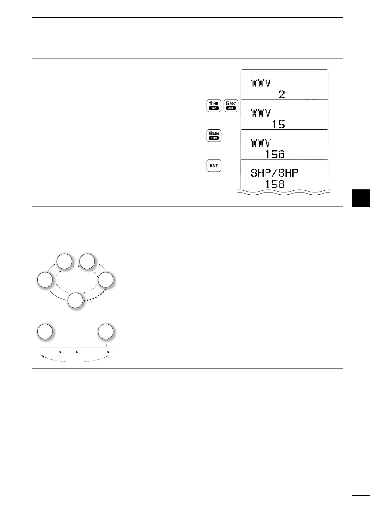
Using the keypad
Direct channel selection via the keypad is available
for quick channel selection.
q Enter the desired channel number via the keypad.
• Pushing [CE] clears input digits and retrieves the channel.
• A user channel is selected when channel 1–160 is
input (max. number may be optionally restricted).
• An ITU SSB channel is selected when channel numbers higher than 401 are input.
• When selecting an ITU simplex channel, push [0
DIM
]
three times to input “– (dash).”
(e.g. When selecting the channel 4-1;
— push [4
SP
××
], [0
DIM
], [0
DIM
], [0
DIM
] then [1NB].)
w Push [ENT] to select the channel.
[EXAMPLE]: Selecting channel 158
LH
CH
---GPS---
Lat
45
59'N
Lon134
44'E
16:23
RX J3E
CH
---GPS---
Lat
45
59'N
Lon134
44'E
16:23
RX J3E
LH
CH
---GPS---
Lat
45
59'N
Lon134
44'E
16:23
RX J3E
LH
CH
---GPS---
Lat
45
59'N
RX J3E
SIMP
DD
Using scan function
The transceiver has automatic channel or frequency
change capability (scan function). There are 3 types
of scan functions available to suit your needs.
Channel scan and channel resume scan increase
channels within a 20 channel range, such as Ch 1 to
Ch 20, Ch 141 to Ch 160, etc., in user channels; or
all channels in the group of ITU channels.
Programmed scan scans frequencies within the frequency range between user channels 159 and 160.
Scan type selection is available in initial set mode.
See p. 46 for the selection.
SCAN OPERATION
q Rotate [GRP] and [CH], or use the keypad to se-
lect your desired channel group.
• This operation is not necessary for programmed scan.
w Push [F] then [2
SQL
] to turn OFF the squelch
function, if programmed scan is selected.
e Push [F] then [3
SCAN
] to start the scan.
r To stop the scan, repeat step e again.
•[CH] rotation or pushing some other switches also
stops the scan.
Channel scan/Channel resume scan
Ch 1
Ch 2 Ch 3
Ch 4
Ch 20
When resume OFF;
scan does not pause even
if a signal is received.
When resume ON;
scan pauses for 10 sec.,
then resumes, or resumes
after 2 sec. from when the
signal disappears.
Programmed scan
Ch 159 Ch 160
Scans the frequency range
between the programmed
frequencies on channels
159 and 160.
Scans fast when squelch is
closed and slowly when
squelch is open.
Page 14
4
10
RECEIVE AND TRANSMIT
■ Basic voice transmit and receive
q Check the following in advance.
➥ Handset or microphone is connected.
➥ No “SQL” indication.
•If “SQL” appears, push [F] then [2
SQL
] to turn the
squelch OFF.
➥ No “” indication.
•If “” appears, push [F] then [4
SP
××
] to activate
the speaker.
➥ The clarity function is not activated.
•If the clarity function is activated, push [F] then
[RX
CLAR
] to turn the function OFF.
w Rotate [GRP] and [CH] to select the desired chan-
nel to be received.
•When receiving a signal, the S-meter shows the signal
strength.
e Adjust [VOL] to the desired audio level when re-
ceiving a signal.
r Push [MODE
SET
] to select the desired operating
mode.
t Push [TUNE
THRU
] to tune the antenna tuner, if con-
nected.
•Skip this operation when the “AUTO TUNE” is set to ON
in initial set mode (p. 46).
y To transmit on the channel, push and hold the PTT
switch on the handset or microphone.
•“TUNE” blinks for 1 to 2 sec. for the first transmission
on a channel when the automatic tuning function is activated.
u Speak into the handset or microphone at your nor-
mal voice level.
•The RF meter shows the output power according to your
voice level.
• If “SWR” appears, check your antenna system.
i Release the PTT switch to return to receive.
[RX CLAR]Microphone
connector
[4
SP
×
] [2 SQL]
[F]
SP
SP
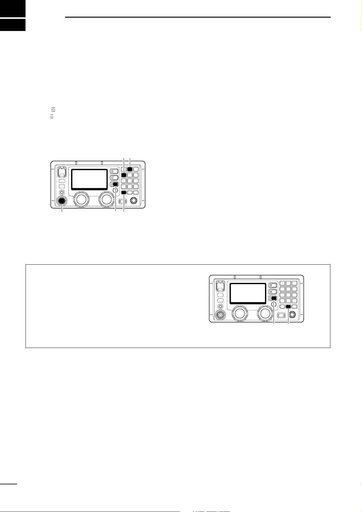
■ Function for transmit
DD
Transmit frequency check
When “DUP” appears in the display such as for a
ship-to-ship channel, the transmit frequency differs
from the receive frequency.
In such cases, the transmit frequency should be monitored before transmitting to prevent interference to
other stations.
➥ Push [F] then push and hold [TX
TXF
] to monitor
the transmit frequency.
•“TX” blinks and the display shows the transmit frequency.
[TX TXF][F]
Page 15
11
4
RECEIVE AND TRANSMIT
4
■ Functions for receive
DD
Squelch function
The squelch function detects signals with voice components and squelches (mutes) unwanted signals
such as unmodulated beat signals. This provides
quiet stand-by.
When you need to receive weak signals, the squelch
should be turned OFF.
➥ Push [F] then [2
SQL
] to switch the function ON
and OFF.
• See page 45 for the squelch level adjustment.
•“SQL” appears when the squelch function is turned ON.
[2 SQL][F]
DD
Noise blanker
The noise blanker function reduces pulse type noise
such as that coming from engine ignitions, etc.
The noise blanker may distort reception of strong signals. In such cases, the noise blanker should be
turned OFF.
➥ Push [F] then [1NB] to switch the function ON and
OFF.
• See page 45 for the noise blanker level adjustment.
•“NB” appears when the NB function is turned ON.
[1 NB][F]
DD
AGC OFF function
The receive gain is automatically adjusted according
to received signal strength with the AGC (Automatic
Gain Control) function to prevent distortion from
strong signals and to obtain a constant output level.
When receiving weak signals with adjacent strong
signals or noise, the AGC function may reduce the
sensitivity. In this situation, the AGC function should
be deactivated.
➥ Push [F] then [5
AGC
××
] to switch the function ON
and OFF.
•“ ” appears when the AGC function is turned OFF.
AGC
[5 AGC×][F]
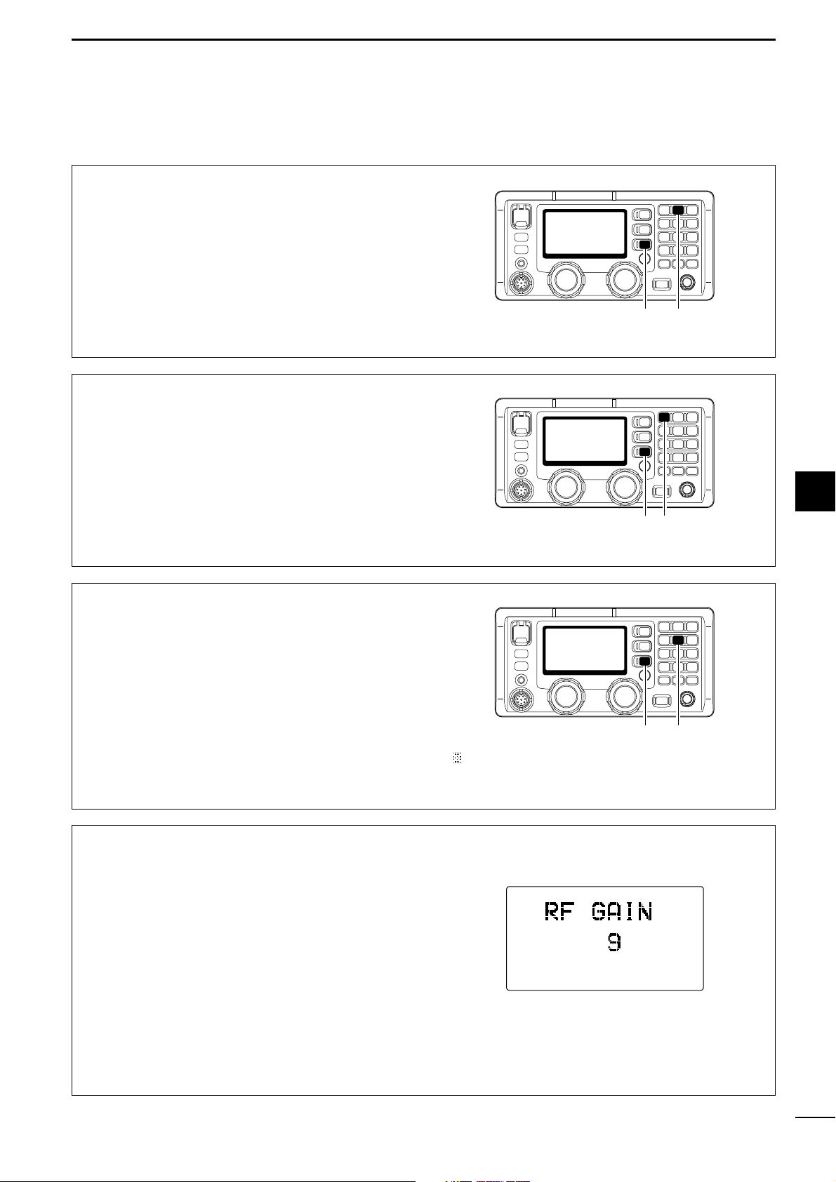
DD
RF gain setting
The receiver gain can be reduced with the RF gain
setting. This may help to remove undesired weak signals while monitoring strong signals.
Usually, the AGC function reduces the RF gain according to the receive signal strength and these weak
signals are removed. However, during no signal reception, these weak signals may not be heard.
In such cases, the RF gain may be useful for setting a
minimum level at which to hear signals.
q Push [F] then [6RF-G] to select the RF gain set
mode, as shown below.
w Rotate [CH] to set the desired minimum cutting
level.
•
“0 (low sensitivity)” to “9 (max. sensitivity)” are available.
• S-meter shows the minimum permitted level.
e Push any key to exit the RF gain set mode.
Page 16
■ Functions for receive (continued)
DD
Clarity control
Voice signals received from other stations may be diffi-
cult to receive. This may sometimes happen if a station is transmitting slightly off frequency. In such cases,
you can compensate by using the clarity control.
q Push [F] then [RX
CLAR
] to switch the function ON
and OFF.
•“CLAR” and shifting value with direction appear.
w Rotate [CH] to improve the audio readability.
• Adjustable between ±150 Hz in 10 Hz steps.
[RX CLAR][CH] [F]
12
4
RECEIVE AND TRANSMIT
■ FSK operation
The transceiver has AFSK operation capability when
an AFSK terminal unit is connected— use J2B for
AFSK operation.
q Connect an AFSK terminal unit to the [AF/MOD]
socket as shown at right.
w Select the desired channel to operate AFSK mode.
e Push [MODE
SET
] several times to select J2B.
r Operate the AFSK terminal unit.
NOTE:
Some transceivers may operate 1.7 kHz higher
than the IC-M801GMDSS’s J2B mode even when
the same displayed frequencies are in use.
AFSK terminal unit connection
1
5
1115
To pins 1, 2
To pin 9
To pin 5
MOD output
MOD ground
AF input
AFSK terminal unit
AF ground
Tx/Rx control
Ground
To pins 3, 4
DD
Tuner through function
In the combination with IC-M801GMDSS and optional
AT-141, the tuner through function can be used.
By bypassing the tuner unit, the receiver gain in particular frequency band may be improved depending
on your antenna element length.
➥ While “TUNE” is displayed, push [F] then
[TUNE
THRU
] to tuner through function ON.
•“THRU” appears instead of “TUNE” indicator.
• Push [TUNE
THRU
] to turn the function OFF.
[TUNE THRU] [F]
Page 17
5
13
CHANNEL NAME PROGRAMMING
4
5
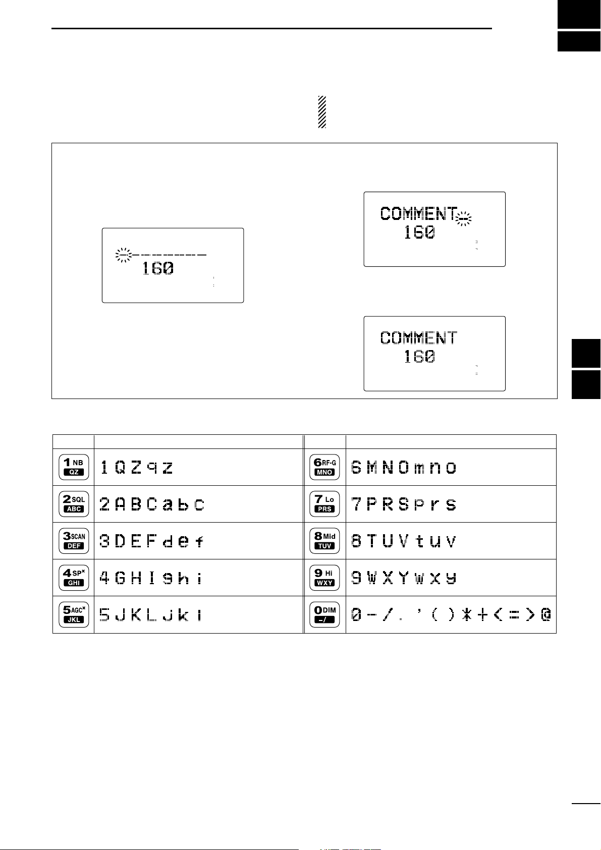
D Programming
q Select the desired channel to be programmed.
w Push [FREQ/CH] to select channel indication
mode, if desired.
e Push [F] then [FREQ/CH].
• The 1st character for the channel names blinks.
r Rotate [CH] selector to select the character for
channel names.
• See the table below for available characters.
t Push the keypad several times to enter that char-
acter.
y Repeat steps r and t to enter the channel name.
u Push [ENT] for 1 sec. to program the channel
name.
CH
---GPS---
Lat
45
59'N
Lon134
44'E
16:23
RX J3E
DUP
0 1 2 3 4A
CH
---GPS---
Lat
45
59'N
Lon134
44'E
16:23
RX J3E
DUP
0 1 2 3 4A
CH
---GPS---
Lat
45
59'N
Lon134
44'E
16:23
RX J3E
DUP
0 1 2 3 4A
Up to 8-character channel names can be assigned for
each user and ITU channel. This may be helpful for indicating the frequency usage, ship name, etc.
NOTE: The display type must be set to “CH-
NAME” to display/program the channel names in ini-
tial set mode. (p. 47).
• Available characters
(space)
KEY CHARACTERS KEY CHARACTERS
Page 18
6
14
FREQUENCY PROGRAMMING
■ Frequency selection
DD
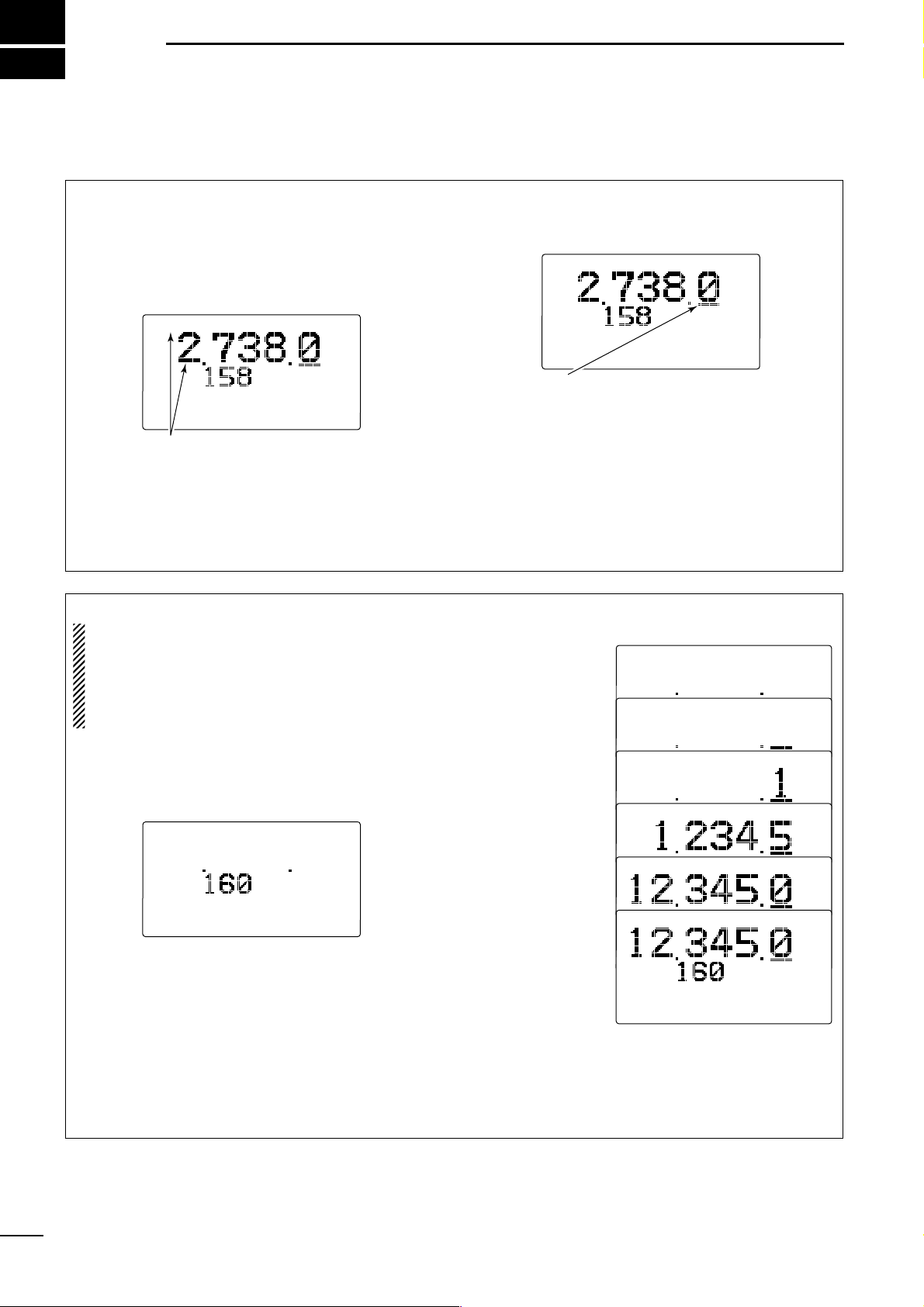
Using the channel selector
q Select a channel which is programmed near the
frequency you want to receive.
w Push [RX
CLAR
] to select the frequency selection
mode.
•“≈” appears in the display.
e Rotate [GRP] to select the digit for tuning.
• Under-bar shows the selected digit.
r Rotate [CH] to tune the frequency.
•Pushing [Y]/[Z] on the microphone also tunes the fre-
quency.
t Repeat steps e and r to complete the frequency
selection.
y To return to the previous frequency, push
[RX
CLAR
].
•“≈” disappears.
0123
4A
CH
---GPS---
Lat
45
59'N
Lon134
44'E
16:23
RX J3E
SIMP
Ç
The under-bar is moved by rotating
[GRP].
0123
4A
CH
---GPS---
Lat
45
59'N
Lon134
44'E
16:23
RX J3E
SIMP
Ç
“Ç” and frequency show that the
frequency can be changed.
DD
Using the keypad
CAUTION: A frequency can be programmed into a
user or e-mail channel by pushing and holding
[ENT] for 1 sec. after entering a frequency. An ITU
simplex frequency can only be programmed on a
temporary basis. Keypad entry should be used only
on spare (or blank) channels.
q Rotate [GRP] and [CH], or enter a 1 to 4 digit num-
ber via the keypad, then push [ENT] to select the
memory channel to be used for general coverage
use.
When a blank channel is selected, operating frequency,
mode and channel name do not appear.
w Push [RX
CLAR
] to select the frequency selection
mode.
•“≈” appears in the display.
e Enter 4 to 6 digits of the desired frequency via the
keypad.
r Push [ENT] momentarily to input the frequency.
•
DO NOT hold [ENT] for more than 1 sec., otherwise the
frequency will be programmed into the channel.
[EXAMPLE]: Setting 12.3450 MHz
•The set frequency can be cleared when [RX
CLAR
] is
pushed while setting.
Ç
Ç
Ç
Ç
0123
4A
CH
---GPS---
Lat
45
59'N
Lon134
44'E
16:23
RX J3E
SIMP
Ç
Select blank channel.
Push [RX
CLAR]
[1
NB]
[2
SQL], [3 SCAN],
[4
SP
×
], [5 AGC×]
[0
DIM]
[ENT]
0123
4A
CH
---GPS---
Lat
45
59'N
Lon134
44'E
16:23
Page 19
15
6
FREQUENCY PROGRAMMING
1
2
3
4
5
6
7
8
9
10
11
12
13
14
15
16
17
Quick Reference
■ Programming a frequency
DD
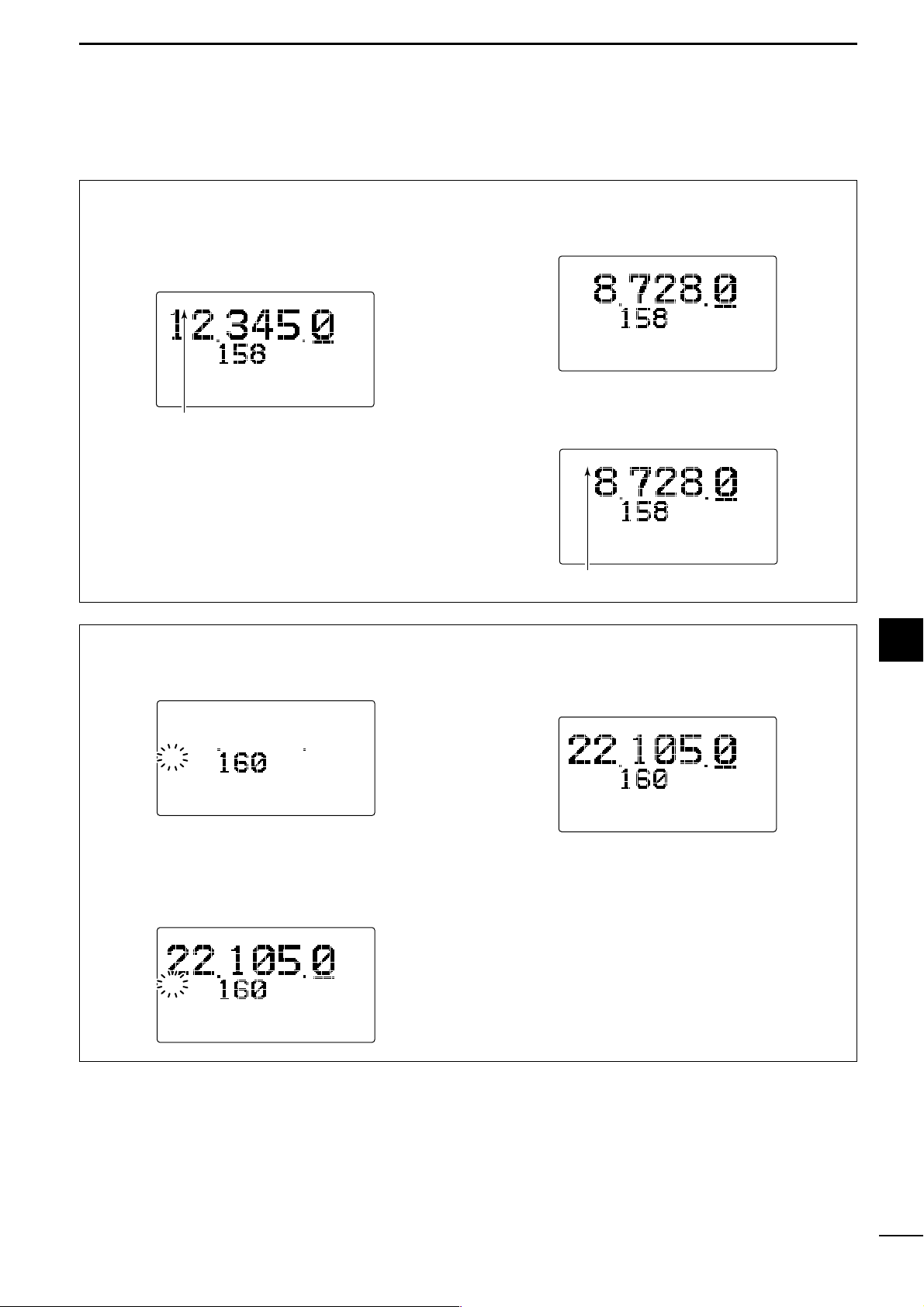
Receive frequency
q Select the desired channel to be programmed.
• Channel 1 to 160 (maximum) are programmable.
w Push [RX
CLAR
] to select the frequency selection
mode.
e Enter 4 to 6 digits of the desired frequency via the
keypad.
• Or rotate [GRP] and [CH] to change the frequency.
•Pushing [Y]/[Z] on the microphone also tunes the fre-
quency.
r Push [MODE
SET
] several times to select the de-
sired operating mode (type of emission).
t Push [ENT] for 1 sec. to program the user chan-
nel.
• 3 beeps sound and “≈” disappears.
0123
4A
CH
---GPS---
Lat
45
59'N
Lon134
44'E
16:23
RX J3E
SIMP
“Ç” indicator disappears when programming is completed.
0123
4A
CH
---GPS---
Lat
45
59'N
Lon134
44'E
16:23
RX J3E
SIMP
Ç
0123
4A
CH
---GPS---
Lat
45
59'N
Lon134
44'E
16:23
RX J3E
SIMP
Ç
“Ç” indicator appears.
DD
Transmit frequency
q Select the desired channel to be programmed.
w Push [TX
TXF
].
e Enter the desired 5 or 6 digit frequency via the key-
pad.
•[GRP] and [CH], as well as [Y]/[Z] on the microphone
cannot be used.
r Push and hold [ENT] for 1 sec. to program the user
channel.
• 3 beeps sound.
0123
4A
CH
---GPS---
Lat
45
59'N
Lon134
44'E
16:23
RX J3E
SIMP
“TX” indicator disappears.
0123
4A
CH
---GPS---
Lat
45
59'N
Lon134
44'E
16:23
RX
TX
J3E
SIMP
0123
4A
CH
---GPS---
Lat
45
59'N
Lon134
44'E
16:23
TX
“TX” indicator blinks.
Page 20
7
16
DSC PREPARATION
■ MMSI code programming
The 9-digit MMSI (Maritime Mobile Service Identity:
DSC self ID) code can be programmed.
This operation is not available when the MMSI code
has been programmed by your dealer. The code reprogramming cannot be performed. This code is displayed during DSC watch mode.
DD
Programming
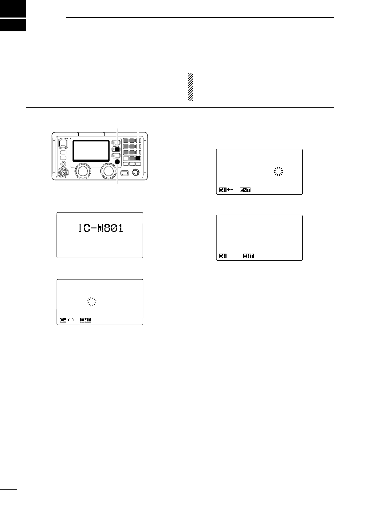
q The following screen will be displayed briefly at
power ON when no MMSI code is programmed.
w Push [DSC] to select MMSI code programming
condition.
e Enter the specified 9-digit MMSI code via the key-
pad.
• Make sure the correct code is entered.
• Rotate [CH] to move the cursor.
r Push [ENT] to program the code.
• After pushing [ENT], DSC menu is displayed as below.
t Push [MODE
SET
] to exit the DSC menu.
******** Set up ********
--------
Select --------
Group
ID
Call
frequency
Traffic
frequency
Scan
frqeuency
Watch
keeping receiver
MMSI
check
Ç
OKSEL
******** Set up ********
---------
MMSI ---------
ID:123456789
OK
******** Set up ********
---------
MMSI ---------
ID:
†
________
OK
<MMSI>
No
MMSI !
1.00
[MODE SET][ENT]
[DSC]
Page 21
17
1
2
3
4
5
6
7
8
9
10
11
12
13
14
15
16
17
Quick Reference
7
DSC PREPARATION
■ Position and time programming
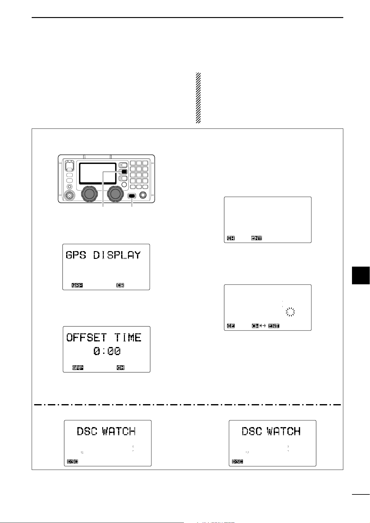
q While pushing and holding [MODE
SET
] push
[POWER] to enter initial set mode.
• Turn the power OFF in advance.
w Rotate [GRP] to select the “GPS DISPLAY” then
rotate [CH] to select the desired position indication
type from simple and detail.
e Rotate [GRP] to select the “OFFSET TIME” then
rotate [CH] to set the time difference between local
and the UTC times within –12 to +12 hours in
10 minute steps.
r Turn the power OFF once, then ON again to exit
quick set mode.
✔ When a position and the UTC time data
(IEC61162-1 format) is applied to [GPS], the following steps are not necessary.
t Push [DSC] to select DSC watch mode.
y Push [MODE
SET
] to enter the DSC menu.
• DSC menu is displayed as below.
u Rotate [CH] to select “Position,” then push
[ENT].
i Enter your position and the UTC time via the key-
pad, then push [ENT].
•Push [3
SCAN
] for the ‘East,’ [9] for the ‘West,’ [6RF-G]
for the ‘North’ and [7] for the ‘South’ setting.
• Rotate [CH] to move the cursor.
o Push [ENT] to program the position and time.
• Return to the “DSC MENU” indication as in step u.
!0 Push [MODE
SET
] to exit the DSC menu.
•Rotate [CH] to select “Exit” then push [ENT] also
exits set mode.
•“MNL” appears instead of “GPS.”
******* Position *******
---
Position & time ----
Latitude
Longitude
UTC
34
34.343N
135
34.343E
12:34
OKNull
******* DSC MENU *******
--------
Select -------Position
Auto ACK
Individual
Group
Geographical
Position R E Q
Ç
OKSEL
*** SET MODE ***
ITEM SEL
*** SET MODE ***
SIMPLE
DETAIL
ÇÇ
ITEM SEL
[POWER][MODE SET]
When no position and the UTC
(Universal Time Coordi-
nated)
time data in IEC61162-1 format, such as from a
GPS receiver, etc., is applied to [GPS] connector, your
position and the UTC time should be input for DSC operation.
IMPORTANT!
Manually programmed position and time data will be
held for 23.5 hours only, and “?” symbol is displayed
for all digits instead of the programmed data after 4
hours from programming.
They are never renewed during the voyage when
the position is set manually.
F1B
GPS
12.345.0
Exit
SP
34
34.000N
135
34.000E
12:34
F1B
GPS
12.345.0
Exit
ACK
ACK
SP
Lat
34
34'N
Lon135
34'E
12:34
• Simple position indication • Detail position indication
MMSI 123456789
MMSI
123456789
2
4 6 8 12
16
Unread
MSG
2 4 6 8 12 16
Unread
MSG
Page 22
8
18
CALL PROCEDURE
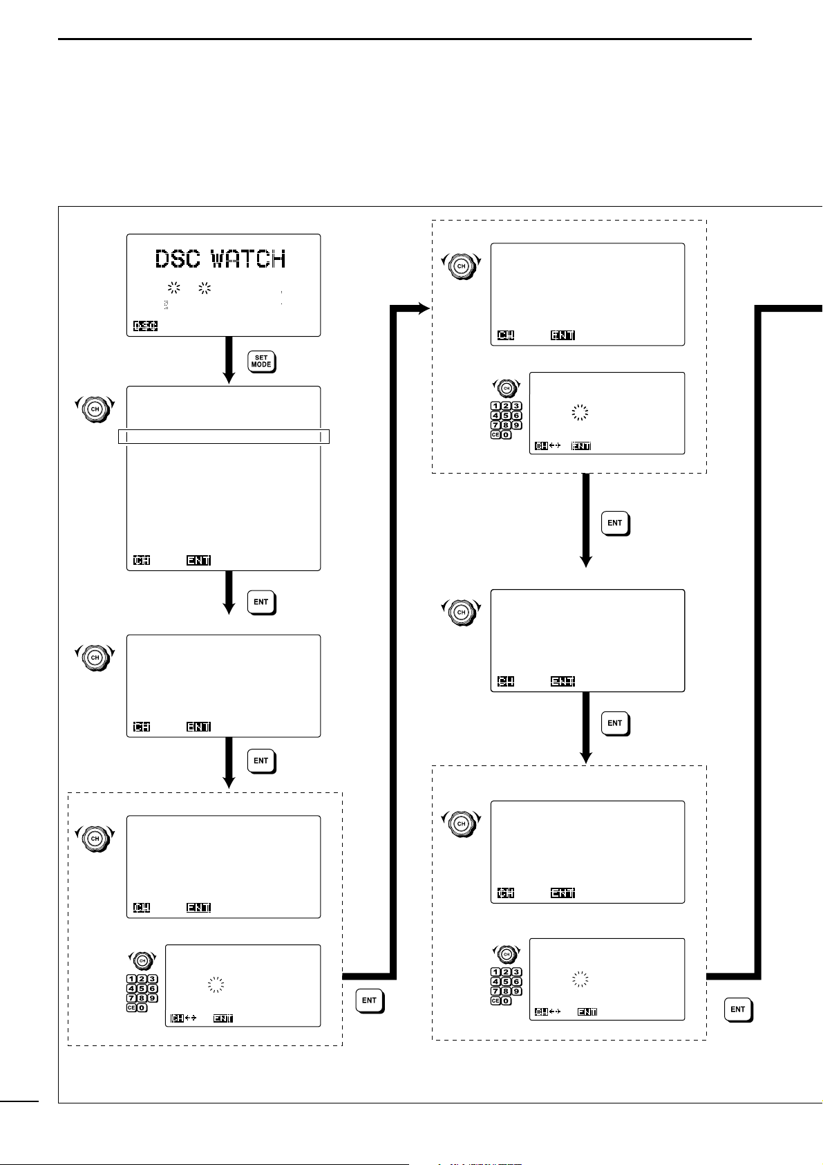
■ Distress call
NEVER USE THE DISTRESS CALL WHEN YOUR
SHIP OR A PERSON IS NOT IN AN EMERGENCY.
DISTRESS CALLS CAN BE USED ONLY WHEN
IMMEDIATE HELP IS NEEDED.
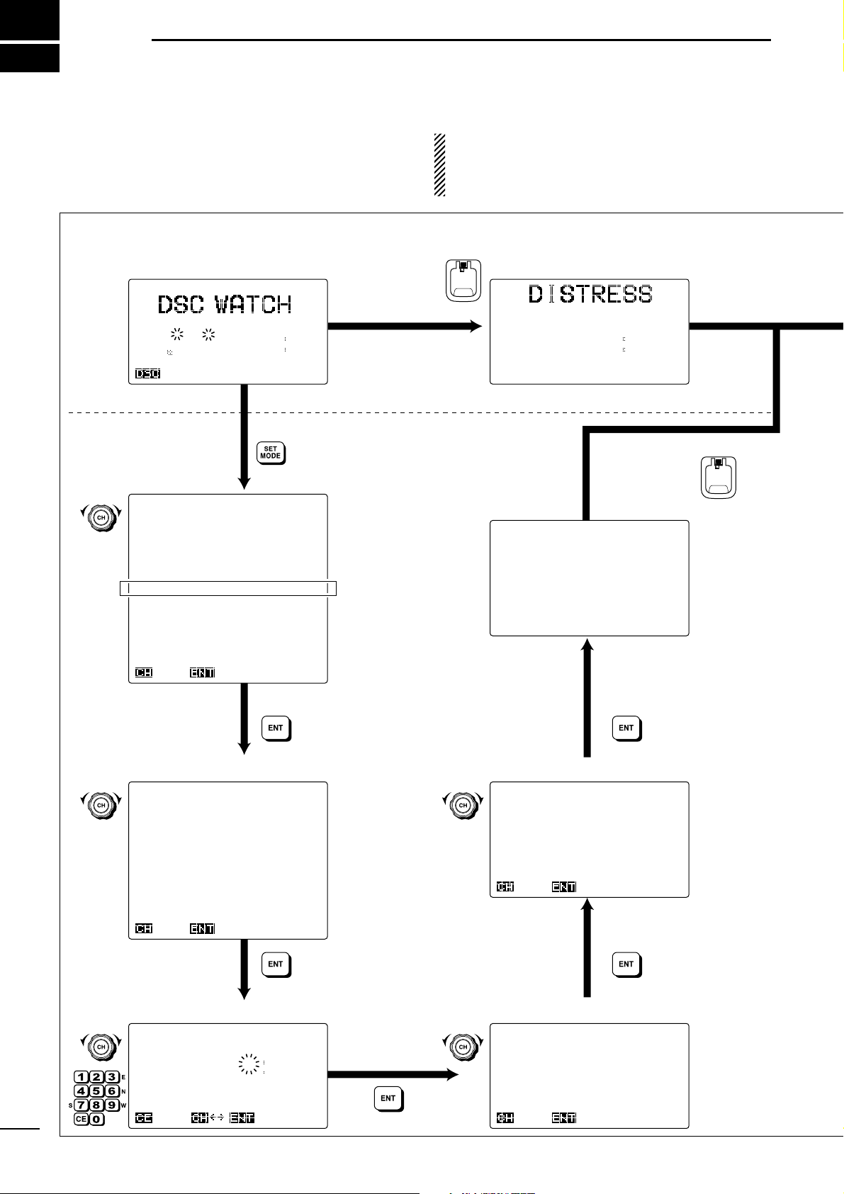
DSC menu
DSC WATCH screen DISTRESS screen
Distress nature selection
Position & UTC time confirmation/setting Subsequent selection
Call frequency selection
Push and hold
[DISTRESS]
for 5 sec.
• Simple distress call
• Regular distress call
DISTRESS
Push and hold
[DISTRESS]
for 5 sec.
DISTRESS
Rotate
Rotate
Rotate Rotate
Rotate
******* Distress *******
---
Position & time ----
Latitude
Longitude
UTC
†4 34.343N
135
34.343E
12:34
OKNull
RX
ACK
F1B
GPS
12.345.0
Exit
SP
Lat
34
34'N
Lon135
34'E
12:34
MMSI 123456789
RX
F1B
8.414.5
<
Push 5sec. >
34 56.789N
123 45.678W
12:34
******* DSC MENU *******
--------
Select -------Position
Auto ACK
Individual
Group
Geographical
Position R E Q
Distress
Distress
RLY
Test
Received Cal l L o g
TX
memory
Set
up
Self
test
Exit
Ç
OKSEL
******* Distress *******
--------
Attempt -------
Single;six
frequency
Single;
2187.5kHz
Single;
4207.5kHz
Single;
6312.0kHz
Single;
8414.5kHz
Single;12577.0kHz
Single;16804.5kHz
OKSEL
Ç
******* Distress *******
Push
DISTRESS for 5sec
Telephony
Telex-FEC
OK
Ç
SEL
******* Distress *******
------
Subsequent ------
******* Distress *******
--------
Nature -------Undesignated
Fire,Explosion
Flooding
Collision
Grounding
Capsizing
Sinking
Adrift
Abandoning
ship
Piracy
Man
overboard
Ç
OKSEL
2 4 6 8 12 16
Page 23
19
8
CALL PROCEDURE
8
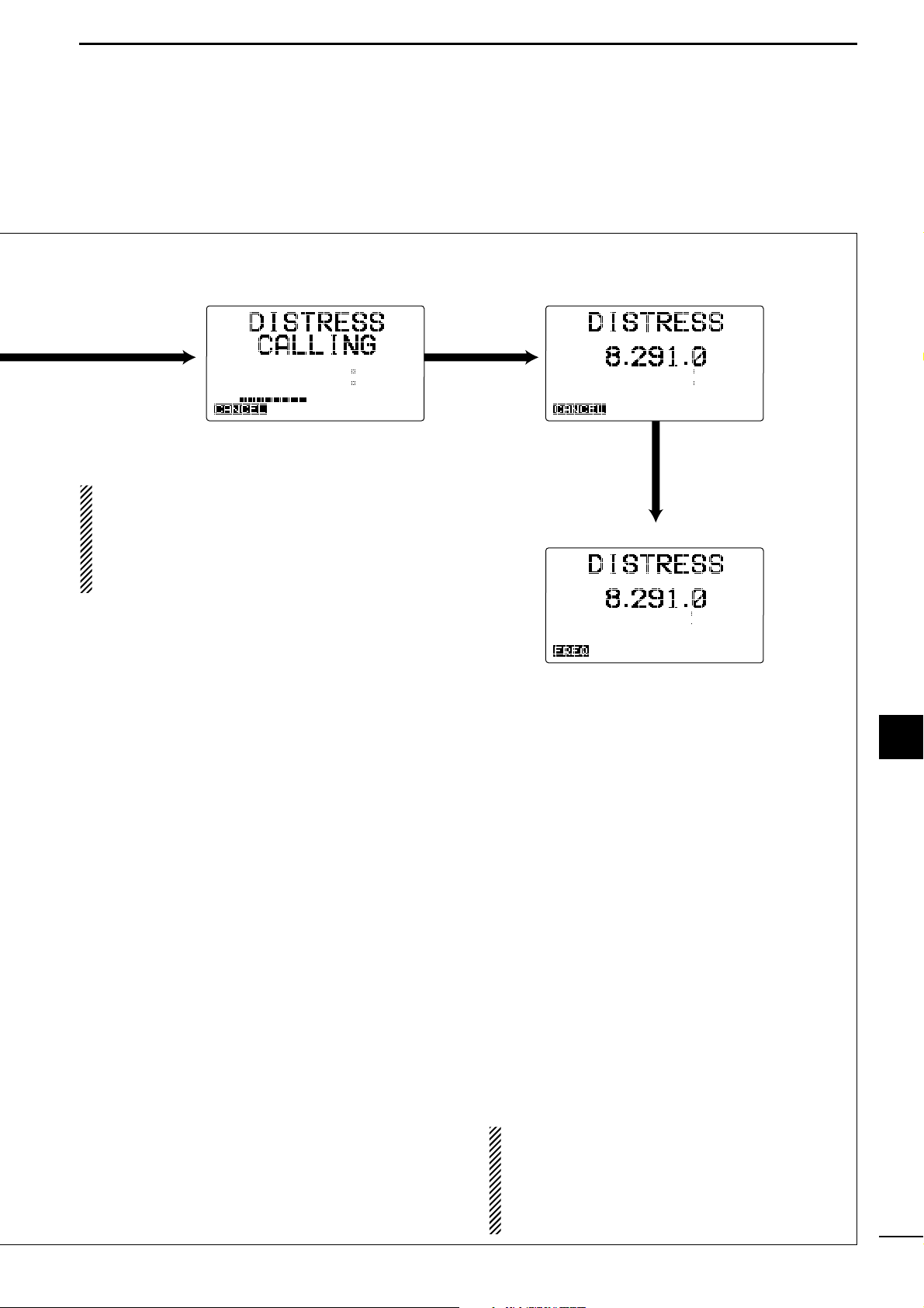
DISTRESS CALLING screen While waiting for the acknowledgement
When the acknowledgement call is received.
After 5 sec.,
starts distress call.
TX
F1B
8.414.5
Exit
34 56.789N
123 45.678W
12:34
RX
J3E
<
Wait for ACK >
Exit
34 56.789N
123 45.678W
12:34
RX
J3E
< ACK received >
Exit
34 56.789N
123 45.678W
12:34
DD
When no acknowledgement is received
If no acknowledgement is received, the ICM801GMDSS automatically transmits the distress call
again every 3.5 to 4.5 minutes.
CAUTION!
DO NOT push [CANCEL] while waiting for an ac-
knowledgement, otherwise the distress call repeat
is cancelled.
Push [CANCEL] only when you want to cancel repeated transmission.
When “Simple distress call” is made;
The distress call is made with the following condition
Nature : Undesignated
Subsequence : Telephony (J3E)
Call frequency : Six frequency
Page 24
20
8
CALL PROCEDURE
■ Individual call
When you use DSC for general selective calling, perform as follows.
****** Individual ******
------
Address ID ------
Manual
set
IC-M801-1
123456789
IC-M801-2
123456788
IC-M801-3
123456787
IC-M801-4
123456786
IC-M801-5
123456785
Ç
OKSEL
******* DSC MENU *******
--------
Select -------Position
Auto ACK
Individual
Group
Geographical
Position R E Q
Distress
Distress
RLY
Test
Received Cal l L o g
TX
memory
Set
up
Self
test
Exit
Ç
OKSEL
****** Individual ******
------
Address ID ------
†
________
OK
****** Individual ******
-------
Category ------Routine
Safety
Urgency
OK
Ç
SEL
****** Individual ******
----
Call frequency ----
Manual
set
T:
2177.0kHz IC-M801-1
R:
2177.0kHz
T: 2189.5kHz INTER2-1
R:
2177.0kHz
OKSEL
Ç
****** Individual ******
----
Call frequency ----
TX:
†
2177.0kHz
RX:_2177.0kHz
OK
****** Individual ******
--
Traffic frequency ---
TX:_2134.0kHz
RX:_2134.0kHz
OK
****** Individual ******
---
1st telecommand ---Telephony
Telex-FEC
Telex-ARQ
DATA
OK
Ç
SEL
-- Traffic frequency --Manual
set
T:
2134.0kHz Traffic-1
R:
2134.0kHz
T:12345.0kHz
Traffic-2
R:12345.0kHz
Ç
OKSEL
****** Individual ******
RX
ACK
F1B
GPS
12.345.0
Exit
SP
Lat
34
34'N
Lon135
34'E
12:34
MMSI 123456789
2 4 6 8 12 16
Unread
MSG
DSC WATCH screen
DSC menu
Category selection
Address ID selection
Manual setting
Call frequency selection
Manual setting
Manual setting
Traffic frequency selection
1st telecommand selection
Rotate
Rotate
Rotate
Rotate
Rotate
Rotate
Rotate
Rotate
Rotate
Page 25

21
8
CALL PROCEDURE
8
****** Individual ******
---------
Call --------To:IC-M801_1
Category:Routine
Call Freq:TX 2177.0kHz
RX 2177.0kHz
Traffic:Telephony
TX 2134.0kHz
RX 2134.0kHz
Write-Menu
Call
RX
F1B
GPS
<
Wait for ACK >
Individual
Lat
34
34'N
Lon135
34'E
12:34
Exit
************************
*
Individual ACK
*
*
IC-M801
*
*
Unable to comply
*
*
Operator unavailable *
************************
Exit
TX
F1B
GPS
Individual
Lat 34 34'N
Lon135
34'E
12:34
Exit
< Calling >
************************
*
Individual ACK
*
*
IC-M801
*
*
Able to comply
*
************************
Exit
Traffic
************************
*
Individual
*
*
ICOM M801
*
************************
ACKExit
≥
≥
≥
Start communication...
Confirmation screen
Start calling
After the call
✔
INFORMATION
The IC-M801GMDSS will not transmit the DSC call (except
emergency call) even [CALL] is pushed and held when the set
calling frequency is in busy. The transceiver waits the DSC call
transmission until the calling frequency becomes clear in this
case.
When no acknowledgement is received;
z Wait for 5 min., then call again on the same or a
different frequency.
x If no acknowledgement is received after a 2nd
call, wait for at least 15 min. before repeating
the call.
Push and hold
for 1 sec.
Push and hold
for 1 sec.
When receiving an acknowledgement, the display shows
the received ID code, or the called station name.
When receiving an acknowledgement with “New traffic”
selection, the display shows as the brand new individual
call reception.
When the called station is unable to comply to the call,
the reason may be displayed.
TX memory
channel
See p. 23 for details.
✔
For your information
When an acknowledgement call with “New traffic” selection is received, the voice communication cannot be started until the communication frequency (=traffic frequency) is decided
between both stations.
Page 26

22
8
CALL PROCEDURE
■ Group call
When you use DSC for calling the desired ship’s
group, use “Group” menu.
********* Group ********
-------
Group ID -------
Manual
set
Group-1
023456789
Group-2
023456788
Group-3
023456787
Group-4
023456786
Group-5
023456785
Ç
OKSEL
********* Group ********
-------
Group ID -------
0
†
_______
OK
******** Group *********
---
1st telecommand ---Telephony
Telex-FEC
OK
Ç
SEL
********* Group ********
--
Traffic frequency ---
TX:
†
2134.0kHz
RX:_2134.0kHz
OK
********* Group ********
----
Call frequency ----
TX:
†
2177.0kHz
RX:_2177.0kHz
OK
******* DSC MENU *******
--------
Select -------Position
Auto ACK
Individual
Group
Geographical
Position R E Q
Distress
Distress
RLY
Test
Received Cal l L o g
TX
memory
Set
up
Self
test
Exit
Ç
OKSEL
********* Group ********
----
Call frequency ----
Manual
set
T:
2177.0kHz Group-1
R:
2177.0kHz
T:
2189.0kHz INTER2-1
R:
2177.0kHz
Ç
OKSEL
********* Group ********
--
Traffic frequency ---
Manual
set
T:
2134.0kHz Traffic-1
R:
2134.0kHz
T:12345.0kHz
Traffic-2
R:12345.0kHz
Ç
OKSEL
RX
ACK
F1B
GPS
12.345.0
Exit
SP
Lat
34
34'N
Lon135
34'E
12:34
MMSI 123456789
2 4 6 8 12 16
DSC menu
Manual setting
1st telecommand selection
Group ID selection
Manual setting
DSC WATCH screen
Manual setting
Call frequency selection
Traffic frequency selection
Rotate
Rotate
Rotate
Rotate
Rotate
Rotate
Rotate
Rotate
Page 27

23
8
CALL PROCEDURE
8
********* Group ********
---------
Call --------To:Group-1
Category:Routine
Call
Freq:TX 2177.0kHz
RX 2177.0kHz
Traffic:Telephony
TX 2134.0kHz
RX 2134.0kHz
Write-Menu
Call
******* TX memory ******
---------
Group -------To:Group-1
Category:Routine
Call Freq:TX 2177.0kHz
RX 2177.0kHz
Traffic:Telephony
TX 2134.0kHz
RX 2134.0kHz
Call
DEL
******* TX memory ******
---------
Select -------
0:Group
Group-1
1:
2:
3:
4:
5:
Ç
OKSEL
********* Group ********
---
TX
memory write ---0:
1:
2:
3:
4:
5:
Ç
WriteSEL
RX
J3E
GPS
<
Traffic >
Lat
34
34'N
Lon135
34'E
12:34
Exit
Group
Exit
Group
TX
J3E
GPS
Lat
34
34'N
Lon135
34'E
12:34
< Calling >
Confirmaition screen
TX memory write channel selection
TX memory channel selection
Start calling...
Start calling...
Push and hold
for 1 sec.
Push and hold
for 1 sec.
TX memory channel
See right for details.
Push and hold
for 1 sec.
Push and hold
for 1 sec.
The IC-M801GMDSS has DSC TX memory. You can store often used DSC calling conditions for quick and simple re-call.
Up to 10 conditions can be stored into the memory with the
following instructions.
✔
CONVENIENT!
Confirmaition screen
Announce the information
Rotate
Rotate
Page 28

***** Geographical *****
-------
Category ------Safety
Urgency
Ç
OKSEL
***** Geographical *****
----
Call frequency ----
2187.5kHz
4207.5kHz
6312.0kHz
8414.5kHz
12577.0kHz
16804.5kHz
OK
Ç
SEL
***** Geographical *****
---------
Area ---------
Ç
OKSEL
Centre-point
Area
***** Geographical *****
-----
Centre-point -----
OK
Latitude
†_ __'N
Longitude
___ __'W
Range:_500nm
***** Geographical *****
---
1st telecommand ---Telephony
Telex-FEC
OK
Ç
SEL
***** Geographical *****
---------
Area ---------
OK
Latitude
†_ N-H:__
Longitude
___ W-V:__
******* DSC MENU *******
--------
Select -------Position
Auto ACK
Individual
Group
Geographical
Position R E Q
Distress
Distress
RLY
Test
Received Cal l L o g
TX
memory
Set
up
Self
test
Exit
Ç
OKSEL
RX
ACK
F1B
GPS
12.345.0
Exit
SP
Lat
34
34'N
Lon135
34'E
12:34
MMSI 123456789
2 4 6 8 12 16
DSC menu
Category selection
Call frequency selection
DSC WATCH screen
Area selection
Centre-point input
Area input
1st telecommand selection
Rotate
Rotate
Rotate
Rotate
Rotate
Rotate
Rotate
24
8
CALL PROCEDURE
■ Geographical call
Use the geographical call when urgency or safety message announcement is necessary to the ships in the
particular area.
Page 29

--------- Call --------To
area: 14 N-H: 3
125 W-V: 3
Category:Safety
Call
Freq:TX 2187.5kHz
RX 2187.5kHz
Traffic:Telephony
TX 2182.0kHz
RX 2182.0kHz
Write-Menu
Call
***** Geographical *****
TX
< Calling >
F1B
GPS
Lat
34
34'N
Lon135
34'E
12:34
Exit
Geographical
RX
J3E
GPS
<
Traffic >
Lat 34 34'N
Lon135
34'E
12:34
Exit
Geographical
***** Geographical *****
--
Traffic frequency ---
TX:
†
2182.0kHz
RX:_2182.0kHz
OK
***** Geographical *****
--
Traffic frequency ---
Manual
set
T:
2134.0kHz Traffic-1
R:
2134.0kHz
T:12345.0kHz
Traffic-2
R:12345.0kHz
Ç
OKSEL
✔ For your information 2— Centre-point input
When using the ‘Geographical’ call with “Centre-point” se-
lection, calls vessels in the square area (“ ” area; not
only round; “ ” area) are called.
Confirmation screen
Start calling...
Push and hold
for 1 sec.
Push and hold
for 1 sec.
Announce the safety or
urgency information
10˚N
100˚W
• Area setting example 1
Latitude
20
N-H:10
Longitude
100 W-V:20
20˚N
80˚W
20˚N/100˚W
10˚N
80˚W
• Area setting example 2
Latitude
20
S-H:10
Longitude
100 E-V:20
20˚S
120˚E
20˚S/100˚E
30˚S
120˚E
30˚S
100˚E
✔ For your information 1— Area input
When using the ‘Geographical’ call with “Area” selection,
your original position is always the upper left hand corner in
the world map as in the following illustration.
• Centre-point setting example
Centre-point
Range
TX memory
channel
See p. 23 for details.
Maual setting
Traffic frequency selection
Rotate
Rotate
25
8
CALL PROCEDURE
8
Page 30

26
8
CALL PROCEDURE
■ Position request call
The position request call is used to confirm the speci-
fied ship’s position. This calling system uses digital sig-
nals only, therefore a voice reply is not necessary.
***** Position R E Q *****
------
Address ID ------
Manual
set
IC-M801-1
001234567
Ç
OKSEL
***** Position RE Q *****
------
Address ID ------
†_
_______
OK
***** Position R E Q *****
----
Call frequency ----
2187.5kHz
4207.5kHz
6312.0kHz
8414.5kHz
12577.0kHz
16804.5kHz
OK
Ç
SEL
TX
< Calling >
F1B
GPS
Lat
34
34'N
Lon135
34'E
12:34
Exit
Position R E Q
************************
*
Position ACK *
*
IC-M801-1
*
*
Lat 3 4 3 4 'N *
*
Lon135 12' E *
************************
***** Position R E Q *****
---------
Call --------To:IC-M801_1
Category:Safety
Call Freq:TX 2187.5kHz
RX 2187.5kHz
Call
Write-Menu
RX
F1B
GPS
<
Wait for ACK >
Lat
34
34'N
Lon135
34'E
12:34
Exit
Position R E Q
******* DSC MENU *******
--------
Select -------Position
Auto ACK
Individual
Group
Geographical
Position R E Q
Distress
Ç
OKSEL
RX
ACK
F1B
GPS
12.345.0
Exit
SP
Lat
34
34'N
Lon135
34'E
12:34
MMSI 123456789
2 4 6 8 12 16
≥
Exit
DSC menu
Address ID selection
Manual setting
Call frequency selection
Confirmation screen
Start calling...
While waitng for the acknowledgement
When the acknowledgement call is received
Push and hold
for 1 sec.
Push and hold
for 1 sec.
TX memory
channel
See p. 23 for details.
DSC WATCH screen
✔ When no acknowledgement is received
q Wait for 5 min., then call again on the same or a
different frequency.
w If no acknowledgement is received after a 2nd
call, wait for at least 15 min. before repeating the
call.
Rotate
Rotate
Rotate
Rotate
Page 31

27
8
CALL PROCEDURE
7
8
9
1
2
3
4
5
6
10
11
12
13
14
15
16
17
Quick Reference
■ Test call
Testing on the exclusive DSC distress and safety calling frequencies (such as 2187.5 kHz) should be avoided
as much as possible by using other methods. When
testing on the distress/safety frequency is unavoidable,
it should be indicated that these are test transmissions.
Normally the test call would require no further communications between the two stations involved.
********* Test *********
------
Address ID ------
00
†
______
OK
********* Test *********
----
Call frequency ----
Manual
set
2187.5kHz
Ç
OKSEL
********* Test *********
----
Call frequency ----
TX:
†
2187.5kHz
RX:_2187.5kHz
OK
********* Test *********
---------
Call ---------
To:Port
ICOM
Category:Safety
Call
Freq:TX 2187.5kHz
RX 2187.5kHz
Call
F1B
GPS
<
Wait for ACK >
Test
Lat
34
34'N
Lon135
34'E
12:34
Exit
******* DSC MENU *******
--------
Select -------Position
Auto ACK
Individual
Group
Geographical
Position R E Q
Distress
Distress
RLY
Test
Received Cal l L o g
TX
memory
Set
up
Self
test
Exit
Ç
OKSEL
********* Test *********
------
Address ID ------
Manual
set
Port
ICOM 001234567
Port
ABC
001234566
Port
M801 001234565
Ç
OKSEL
************************
*
Test ACK
*
*
Port
*
************************
Exit
RX
ACK
F1B
GPS
12.345.0
Exit
SP
Lat
34
34'N
Lon135
34'E
12:34
MMSI 123456789
2 4 6 8 12 16
≥
DSC menu
Manual setting
Call frequency selection
Address ID selection
After the call
Confirmation screen
Manual setting
Test ACK screen
DSC WATCH screen
When receiving an acknowledgement,
the display shows the received ID code,
or ID name, if programmed.
Push and hold
for 1 sec.
Start calling...
Rotate
Rotate
Rotate
Rotate
Rotate
Page 32

9
28
WHEN RECEIVING A CALL
■ To receive a DSC call
The independent built-in DSC receiver circuit in the ICM801GMDSS scans all distress/safety frequencies,
therefore, the “distress,” “urgency” and “safety” calls on
those frequencies can be decoded at all times.
However, “routine” and “group” calls on the other fre-
quencies are received via the transceiver’s receiver
circuit. Therefore, the transceiver must set to DSC
watch mode by pushing [DSC] to decode these calls.
DD
When receiving a DSC call
One of the following actions should be performed
when a DSC call is received depending on the received DSC format (or category):
•Wait for a voice transmission on the traffic frequency.
• Transmit an acknowledgement with DSC or voice.
DD
Display example and operation
• Monitoring the traffic frequency
Monitor the communication between the calling ship
and a coast station, or the calling station transmission
via voice on the traffic frequency.
•Emergency alarm sounds until pushing some key, or
beeps sound, depending on the calling format or category.
• Transmit an acknowledgement
When the following DSC is received, an acknowledgement must be sent back to the calling station.
•Beeps, or an emergency alarm sounds until pushing
some key, depending on the category.
✔
For your information
By rotating [CH], the received information can be read
(not all contents in some calling category)
without entering
DSC memory screen as described in the next page.
************************
*
Individual
*
*
ICOM M801
*
************************
TrafficExit
************************
*
Position REQ
*
*
ICOM M801
*
************************
ACKExit
************************
*
Polling REQ
*
*
001234567
*
************************
ACKExit
≥
************************
*
Distress ACK
*
*
001234567
*
************************
************************
*
Distress RLY
*
*
123456789
*
************************
TrafficExit
************************
*
Distress
*
*
123456789
*
************************
TrafficExit
************************
*
Group
*
*
ICOM M801
*
************************
TrafficExit
************************
*
Geographic
*
*
123456789
*
************************
TrafficExit
************************
*
Geographical
*
*
123456789
*
************************
TrafficExit
≥
Page 33

29
9
WHEN RECEIVING A CALL
1
2
3
4
5
6
7
8
10
11
12
13
14
15
16
17
Quick Reference
9
■ Received information
When receiving a DSC call, the received format specifier and its contents are memorized into the received
call log. Distress calls (including other calls with a distress category) are stored separately from other calls.
Up to 20 distress and up to 20 other calls can be memorized.
q During DSC watch mode, push [RX
CLAR
] to enter
the received DSC memory select screen.
•Or, push [MODE
SET
], rotate [CH] to select “Re-
ceived Call Log” then push [ENT].
w Rotate [CH] to select the desired category from
“Distress” and “Others” then push [ENT].
•“Unread message” is displayed beside category
when a message have not been read is available in the
category.
•“<No data>” is displayed beside category when no
received message is stored in the category.
e Rotate [CH] to select the desired DSC message.
•“*” means the DSC messages have not been read.
•“DTRS RLY” stands for distress relay.
• Distress memory screen
• Others memory screen
r Push [ENT] to indicate the contents.
•Rotate [CH] to scroll text to see hidden lines information.
t Push [ENT] to selects the traffic screen and moni-
tor the traffic frequency.
y Push [RX
CLAR
] to dispaly the DSC message
under the traffic frequency indication.
•Rotate [CH] to scroll text to see hidden lines information.
•Push [RX
CLAR
] to return to the indication as step t.
u Push [FREQ/CH] to return to DSC watch mode.
NOTE:
When the DSC message with “?” symbol is selected in step e, the message “DATA ERROR” is
displayed at the bottom of the line in memory contents screen in step r.
RX
J3E
< Traffic >
Exit
Traffic
------- Distress ------Distress
ID:123456789
Undesignated
Position:Lat
34
34'N
Lon134 34'W
UTC 12:34
RX
Freq:TX 2187.5kHz
RX 2187.5kHz
Traffic:Telephony
TX 2182.0kHz
RX 2182.0kHz
RX
J3E
< Traffic >
Lat 34 34'N
Lon135
34'E
12:34
Exit
GPS
MSG
** Received Cal l L o g ***
-------
Distress -------
Distress
ID:123456789
Undesignated
Position:Lat
34
34'N
Lon134 34'W
UTC 12:34
Angle:123
Distance:1234nm
RX
Freq:TX 2187.5kHz
RX 2187.5kHz
Traffic:Telephony
TX 2182.0kHz
RX 2182.0kHz
DEL
OKCancel
** Received Cal l L o g ***
--------
Select --------
123456789
111111111
123123123
123456788
SEL
OK
Ç
Individual
Individual
Geographic
Individual
*
*
** Received Cal l L o g ***
--------
Select -------Distress
DTRS
ACK
DTRS
RLY
Distress
DTRS
ACK
Distress
SEL
OK
Ç
123456789
111111111
123123123
123123123
123123123
123234234
*
*
*
*
** Received Cal l L o g ***
--------
Select -------Distress
Others
Unread
message
Unread
message
Ç
OKSEL
Page 34

30
9
WHEN RECEIVING A CALL
➥ When the desired memory contents to be deleted
are displayed as at right, push and hold [CE] for
1 sec.
•After erasing, the receive memory select screen, as in
step e of “■ Received information,” is selected automatically.
•The DSC memory, which 48 hours or more have been
passed from received, can only be deleted.
** Received Cal l L o g ***
-------
Distress -------
Distress
ID:123456789
Undesignated
Position:Lat
34
34'N
Lon134 34'W
UTC 12:34
Angle:123
Distance:1234nm
RX
Freq:TX 2187.5kHz
RX 2187.5kHz
Traffic:Telephony
TX 2182.0kHz
RX 2182.0kHz
DEL
OKCancel
■ Deleting a memory
Page 35

31
9
WHEN RECEIVING A CALL
1
2
3
4
5
6
7
8
9
10
11
12
13
14
15
16
17
Quick Reference
■ Distress call
***** Distress RLY *****
-----
Select Call ------
Address
ID
Area
Ç
OKSEL
RX
J3E
<
Traffic >
Lat 34 34'N
Lon135
34'E
12:34
Exit
GPS
************************
*
Distress
*
*
123456789 *
************************
TrafficExit
******* DSC MENU *******
--------
Select -------Position
Auto ACK
Individual
Group
Geographical
Position R E Q
Distress
Distress
RLY
Test
Received Cal l L o g
TX
memory
Set
up
Self
test
Exit
Ç
OKSEL
RX
ACK
F1B
GPS
12.345.0
Exit
SP
Lat
34
34'N
Lon135
34'E
12:34
MMSI 123456789
2 4 6 8 12 16
Unread
MSG
MSG
RX
J3E
< Traffic >
Exit
Traffic
------- Distress ------Distress
ID:123456789
Undesignated
Position:Lat
34
34'N
Lon134 34'W
UTC 12:34
RX
Freq:TX 2187.5kHz
RX 2187.5kHz
Traffic:Telephony
TX 2182.0kHz
RX 2182.0kHz
≥
D Distress relay call operation
When a distress call is received
Monitoring
DSC WATCH screen
Received DSC message indication
DSC menu
Distress relaly call selection
Continue to the next page
Distress call reception should stop after one
sequence since the coast station should
send back an ‘acknowledgement’ to the ship.
If the distress call continues, the coast station
may not be receiving the call. In such cases,
you should contact the ship via the phone.
When the ship requires a ‘distress relay’ call
or the ship appears not to reply, proceed as
follows for ‘distress relay’ transmission.
Rotate
Rotate
Page 36

32
9
WHEN RECEIVING A CALL
DD
Distress relay call operation— continued
***** Distress RLY *****
------
Address ID ------
Manual
set
Port
Icom1 001234567
Port
Icom2 001234568
Port
Icom3 001234569
Ç
OKSEL
***** Distress RLY *****
-----
Select Call ------
Address
ID
Area
Ç
OKSEL
***** Distress RLY *****
------
Address ID ------
00
†
______
OK
***** Distress RLY *****
--------
Select --------
OK
SEL
123456789
987654321
Manual
set
Ç
***** Distress RLY *****
-----
Distress ID ------
Are
you sure?
†
________
OK
***** Distress RLY *****
--------
Nature -------Undesignated
Fire,Explosion
Flooding
Collision
Grounding
Capsizing
Ç
***** Distress RLY *****
---------
Area ---------
Ç
OKSEL
Centre-point
Area
***** Distress RLY *****
-----
Centre-point -----
OK
Latitude
†_ __'N
Longitude
___ __'W
Range:_500nm
***** Distress RLY *****
---------
Area ---------
OK
Latitude
†_ N-H:__
Longitude
___ W-V:__
Area selection
Centre-point setting
Area setting
Rotate
Rotate
Rotate
Distress nature selection
Address ID selection
Distress relay call selection
Distress relay selection
Manual setting
Manual setting
Rotate
Rotate
Rotate
Rotate
Rotate
Rotate
Page 37

33
9
WHEN RECEIVING A CALL
1
2
3
4
5
6
7
8
9
10
11
12
13
14
15
16
17
Quick Reference
***** Distress RLY *****
---
Position & time ----
Latitude
Longitude
UTC
†4 34.343N
135
34.343E
12:34
OKNull
***** Distress RLY *****
----
Call frequency ----
2187.5kHz
4207.5kHz
6312.0kHz
8414.5kHz
12577.0kHz
16804.5kHz
Ç
OKSEL
***** Distress RLY *****
---------
Call ---------
Selected
distress
call is received
11H 34min
before
To:001234567
Distress
ID:123456789
Undesignated
Position
:Lat 34 34.000N
Lon134 34.000W
UTC 12:34
Call
Freq:TX 2187.5kHz
RX 2187.5kHz
Traffic:Telephony
TX 2182.0kHz
RX 2182.0kHz
Call
TX
< Calling >
F1B
GPS
Lat
34
34'N
Lon135
34'E
12:34
Exit
Distress RLY
RX
J3E
GPS
<
Traffic >
Lat
34
34'N
Lon135
34'E
12:34
Exit
Distress RLY
Subsequent selection
Rotate
Telephony
Telex-FEC
OK
Ç
SEL
***** Distress RLY *****
------
Subsequent ------
Position & UTC time confirmation/setting
Call frequency selection
Confirmation screen
Start calling...
Push and hold
for 1 sec.
Rotate
Rotate
Page 38

34
9
WHEN RECEIVING A CALL
■ Distress acknowledgement call
***** Distress ACK *****
--------
Select -------123456789
123456788
Ç
OKSEL
***** Distress ACK *****
---------
Call ---------
Distress
ID:123456789
Undesignated
Position
:Lat 34 34.000N
Lon134 34.000W
UTC 12:34
Call
Freq:TX 2187.5kHz
RX 2187.5kHz
Traffic:Telephony
TX 2182.0kHz
RX 2182.0kHz
Call
TX
< Calling >
F1B
GPS
Lat
34
34'N
Lon135
34'E
12:34
Exit
Distress ACK
RX
J3E
GPS
<
Traffic >
Lat
34
34'N
Lon135
34'E
12:34
Exit
RX
J3E
<
Traffic >
Lat 34 34'N
Lon135
34'E
12:34
Exit
GPS
************************
*
Distress ACK
*
*
123456789 *
************************
TrafficExit
******* DSC MENU *******
--------
Select -------Position
Auto ACK
Individual
Group
Geographical
Position R E Q
Distress
Distress
ACK
Distress
RLY
Test
Received Cal l L o g
TX
memory
Set
up
Self
test
Exit
Ç
OKSEL
RX
ACK
F1B
GPS
12.345.0
Exit
SP
Lat
34
34'N
Lon135
34'E
12:34
MMSI 123456789
2 4 6 8 12 16
Unread
MSG
≥
MSG
D Distress acknowledgement call operation
When a distress acknowledgement call is received Monitoring
DSC WATCH screen
DSC menu
Address ID selection
Confirmation screen
Start calling...
Push and hold
for 1 sec.
Distress call reception should stop after one sequence since the coast station should send back
an ‘acknowledgement’ to the ship. If the distress
call continues even the coast station send back an
‘acknowledgement,’ the ship in distress may not
be receiving the call.
In such cases, you should contact the coast station via the phone and send back an
‘acknowledgement’ on be half of the coast station
if the coast station requires.
NOTE: The distress acknowledgement call can be
made for the distress call received on
2187.5 MHz only.
The “Distress ACK” selection in DSC
menu screen will not be displayed when a
distress call on another frequency, such as
8414.5 MHz, is received.
Rotate
Rotate
Page 39

35
9
WHEN RECEIVING A CALL
1
2
3
4
5
6
7
8
9
10
11
12
13
14
15
16
17
Quick Reference
■ Distress relay call
DSC menu
Distress relay call selection
When a distress relay call is received
DSC WATCH screen
Received DSC contents screen
D Distress relay acknowledgement call
operation
(available only when individual dis-
tress relay call is received)
Start calling...
Confirmation screen
Rotate
Rotate
Push and hold
for 1 sec.
*** Distress RLY ACK ***
--------
Select --------
OK
SEL
001234567
007654321
Ç
*** Distress RLY ACK ***
---------
Call --------To:001234567
Distress
ID:123456789
Undesignated
Position:Lat
34
34'N
Lon134 34'W
UTC 12:34
Call
Freq:TX 2187.5kHz
RX 2187.5kHz
Traffic:Telephony
TX 2182.0kHz
RX 2182.0kHz
Call
************************
*
Distress RLY
*
*
001234567
*
************************
TrafficExit
******* DSC MENU *******
--------
Select --------
Position
Auto ACK
Individual
Group
Geographical
Position R E Q
Distress
Distress
RLY
Distress
RLY ACK
Test
Received Cal l L o g
TX
memory
Set
up
Self
test
Exit
Ç
OKSEL
RX
ACK
F1B
GPS
12.345.0
Exit
SP
Lat
34
34'N
Lon135
34'E
12:34
MMSI 123456789
2 4 6 8 12 16
MSG
MSG
RX
J3E
<
Traffic >
Lat 34 34'N
Lon135
34'E
12:34
Exit
GPS
TrafficExit
----- Distress RLY ----From:001234567
Distress
ID:123456789
Undesignated
Position:Lat
34
34'N
Lon134 34'W
UTC 12:34
RX
Freq:TX 2187.5kHz
RX 2187.5kHz
Traffic:Telephony
TX 2182.0kHz
RX 2182.0kHz
RX
J3E
<
Traffic >
≥
Page 40

36
9
WHEN RECEIVING A CALL
■
Individual call
When receiving an Individual call, beeps may sound
(or the emergency alarm depending on the category)
and the display below appears.
** Received Cal l L o g ***
------
Individual ------
From:ICOM
M801
Category:Routine
RX
Freq:TX 12345.0kHz
RX 12345.0kHz
Traffic:Telephony
TX 2345.0kHz
RX 2345.0kHz
DEL
ACKCancel
**** Individual ACK ****
--------
Comply -------Able
Unable
New
traffic
DEL
ACKCancel
Ç
************************
*
Individual
*
*
ICOM M801
*
************************
ACKExit
Calling station’s name appears when
the same ID is preprogrammed.
**** Individual ACK ****
---------
Call ---------
To:ICOM
M801
Category:Routine
Call
Freq:TX 12345.0kHz
RX 12345.0kHz
Traffic:Telephony
TX 2345.0kHz
RX 2345.0kHz
Call
-- Traffic frequency ---
Manual
set
T:
2134.0kHz SHIP
R:
2134.0kHz
T:12345.0kHz
IC-M801-2
R:12345.0kHz
Ç
OKSEL
**** Individual ACK ****
-- Traffic frequency ---
TX:_2134.0kHz
RX:_2134.0kHz
OK
**** Individual ACK ****
RX
J3E
<
Traffic >
Lat
34
34'N
Lon135
34'E
12:34
Exit
GPS
Individual
ACK
≥
When an individual call is received
Received call log screen
Comply selection
New traffic
frequency selection
Confirmation screen
Manual setting
Push and hold
for 1 sec.
Go to “Confirmation screen”
on p. 21.
✔
For your information
When an acknowledgement call with “New traffic” selection is made, the voice communication cannot be started until the communication
frequency (=traffic frequency) is decided between both stations.
Start calling...
Start communication...
Rotate
Rotate
Rotate
Page 41

37
9
WHEN RECEIVING A CALL
9
**** Individual ACK ****
--------
Comply --------
No
reason given
Busy
Channel
unable
Mode
unable
Operator
unavailable
No
operator
Station
barred
Equipment
disable
Congestion
Queue
indication
SEL
OK
Ç
**** Individual ACK ****
---------
Call ---------
To:ICOM
M801
Category:Routine
Unable
to
comply
Reason:
Operator unavailable
Call
Freq:TX 12345.0kHz
RX 12345.0kHz
Call
******* Auto ACK *******
--------
Select -------Manual set
Abl e t o comply
Unable to comply
OK
Ç
SEL
******* Auto ACK *******
--------
Reason -------No reason given
Busy
Channel unable
Mode unable
Operator unavailable
No operator
Station barred
Equipment disable
Congestion
Queue indication
OK
Ç
SEL
******* DSC MENU *******
--------
Select -------Position
Auto ACK
Individual
Group
Geographical
Position R E Q
Distress
Distress
RLY
Test
Received Cal l L o g
TX
memory
Set
up
Self
test
Exit
Ç
OKSEL
RX
ACK
F1B
GPS
12.345.0
Exit
SP
Lat
34
34'N
Lon135
34'E
12:34
MMSI 123456789
2 4 6 8 12 16
MSG
RX
ACK
F1B
GPS
12.345.0
Exit
SP
Lat
34
34'N
Lon135
34'E
12:34
MMSI 123456789
2 4 6 8 12 16
MSG
Confirmation screen
“Unable”
reason selection
DSC menu
DSC WATCH screen
DSC WATCH screen
ACK selection
D Auto ACK setting
“Unable”
reason selection
Push and hold
for 1 sec.
✔
About “Auto ACK” setting
When “Able to comply” or “Unable to comply”
is selected with Auto ACK setting as at right,
the acknowledgement call is made automatically— no acknowledgement call operation is
necessary.
When “Manual set” is selected, acknowledgement call operation is necessary, however, the
acknowledgement call with the reason “No operator” is made automatically when no operation is performed for 25 sec. from the call reception.
Start calling...
Rotate
Rotate
Rotate
Rotate
Page 42

38
9
WHEN RECEIVING A CALL
■ Group call
************************
*
Group
*
*
ICOM M801
*
************************
TrafficExit
Calling station’s name appear when
the same ID is preprogrammed.
RX
J3E
<
Traffic >
Lat
34
34'N
Lon135
34'E
12:34
Exit
GPS
Group
RX
ACK
F1B
GPS
12.345.0
Exit
SP
Lat
34
34'N
Lon135
34'E
12:34
MMSI 123456789
2 4 6 8 12 16
Unread
MSG
≥
MSG
When a group call is received Traffic screen
DSC WATCH screen
■ Polling call
************************
*
Polling REQ
*
*
001234567
*
************************
ACKExit
** Received Cal l L o g ***
-----
Polling REQ -----From:001234567
Category:Routine
RX Freq:TX 2177.0kHz
RX 2177.0kHz
ACK
Cancel
***** Polling ACK ******
To:001234567
Category:Routine
RX Freq:TX 2177.0kHz
RX 2177.0kHz
Call
--------- Call ---------
RX
ACK
F1B
GPS
12.345.0
Exit
SP
Lat
34
34'N
Lon135
34'E
12:34
MMSI 123456789
2 4 6 8 12 16
MSG
≥
When a polling request call is received
Received call log screen
Conrimation screen
DSC WATCH screen
Push and hold
for 1 sec.
Start calling...
Page 43

39
9
WHEN RECEIVING A CALL
9
■ Geographical area call
NOTE: The IC-M801GMDSS will not function for the
geographical call when your position is out of the
specified area.
ACK
************************
*
Position REQ
*
*
ICOM M801
*
************************
Exit
** Received Cal l L o g ***
-----
Position REQ -----
From:ICOM
M801
Category:Safety
RX
Freq:TX 12345.0kHz
RX 12345.0kHz
ACK
Cancel
***** Position ACK *****
---
Position & time ----
Latitude
Longitude
UTC
34
34.567N
134 34.567W
12:34
Null
OK
***** Position ACK *****
---------
Call ---------
To:ICOM
M801
Category:Safety
Position
:Lat 34 34.567N
Lon134 34.567W
UTC 12:34
Call
Freq:TX 12345.0kHz
RX 12345.0kHz
Call
Push and hold
for 1 sec.
RX
ACK
F1B
GPS
12.345.0
Exit
SP
Lat
34
34'N
Lon135
34'E
12:34
MMSI 123456789
2 4 6 8 12 16
Unread
MSG
Appears and operation is necessary only when “Manual set” is selected for Auto ACK setting. (p. 48)
≥
When a position request is received
Received call log screen
Position & UTC time confirmation
Confirmation screen
DSC WATCH screen
Rotate
Start calling...
■ Position request call
When a geographical call is received Monitoring
************************
************************
*
*
*
*
************************
************************
Geographical
Geographic
123456789
123456789
*
TrafficExit
TrafficExit
*
*
*
≥
RX
DSC WATCH screen
2 4 6 8 12 16
RX
Geographical
<
Traffic >
GPS
Exit
Lat
Lon134
MSG
34
12:34
MMSI 123456789
12.345.0
SP
Exit
Lat
GPS
Lon135
MSG
F1B
34
12:34
J3E
34'N
34'E
ACK
34'N
34'E
Page 44

10
40
MEMORY OPERATION
■ Memory description
The IC-M801GMDSS has several kinds of memories
as follows:
• Address and group ID code memories (p. 41)
• Call, traffic and scan frequency memories (p. 42)
•DSC transmission memory (described in this section)
• Received message memory (p. 29)
■ Memory writing
10 DSC transmission memory channels allow you to
set often used format specifiers and contents such as
for routine calls, group calls, etc.
q During DSC watch mode, select the desired format
category (except distress and test), and set the
message, call and traffic frequencies until the call
stand-by screen is displayed as described in the
CALL PROCEDURE section (pgs. 18–27).
w Push and hold [ENT] for 1 sec. to select the TX
memory write condition.
e Rotate [CH] to select the desired memory channel.
r Push and hold [ENT] for 1 sec. again to store the
condition into the selected memory channel.
•The set DSC format and calling station ID/name appear.
t Push [ENT] to return to the calling stand-by condi-
tion, or push [MODE
SET
] to return to DSC watch
mode.
--- TX memory write ---0:Individual
987654321
1:
2:
3:
4:
5:
Ç
OKSEL
--- TX memory write ---0:
1:
2:
3:
4:
5:
Ç
WriteSEL
■ Memory reading/transmitting/deleting
q Push [DSC] to select DSC watch mode, if neces-
sary.
w Push [TX
TXF
] to enter the DSC transmit memory
screen.
•Or, push [MODE
SET
], rotate [CH] to select “TX
memory” then push [ENT], also selects the transmit
memory screen.
e Rotate [CH] to select the selected memory chan-
nel to be read.
r Push [ENT] to display the memory contents.
t Operate as follows:
➥ When reading the memory contents only;
•Push [MODE
SET
] to return to DSC watch
mode.
➥ When transmitting the memory contents;
• Push and hold [CALL] for 1 sec.
➥ When clearing the memory contents;
• Push and hold [CE] for 1 sec.
****** TX memory *******
------
Individual -----To:987654321
Category:Routine
Call Freq:TX 2187.5kHz
RX 2187.5kHz
Traffic:Telephony
TX 2134.0kHz
RX 2134.0kHz
DEL
Call
****** TX memory *******
--------
Select --------
0:Individual
987654321
1:
2:
3:
4:
5:
Ç
OKSEL
Page 45

11
41
DSC MENU OPERATION
1
2
3
4
5
6
7
8
9
10
11
12
13
14
15
16
17
Quick Reference
■ General
Up to 100 ID codes with frequency and name can be
programmed in MENU mode for easy recall during
DSC call setting.
In addition, the following settings/operation are available in DSC setup menu.
• Manual position/time setting (p. 17)
•Self-ID (MMSI code) indication (described in this sec-
tion; p. 43)
■ ID input
A total of 100 ID codes can be programmed as “Address ID” (for ships and coast stations) and “Group ID”
(for group stations).
A pair of frequencies (both transmit and receive) and
ID name are also programmed together with the ID
code which are used as call frequencies when using
the ID code.
q During DSC menu indication, rotate [CH] to select
“Set up” then push [ENT] to select setup menu.
• The select screen is displayed as below.
w Rotate [CH] to select the “Address ID” or
“Group ID,” then push [ENT].
• The address/group ID list screen is displayed.
When the memory is full:
“Memory full” is displayed beside “<add>”
indication when 100 ID codes have been programmed.
Delete any unnecessary IDs in such cases (see
p. 44 for delete)
.
e Rotate [CH] to select “<add>” then push [ENT].
• The address/group ID setup screen is displayed.
r Push the numeral keys to input the desired 10-digit
ID name, 9-digit code and both transmit and receive frequencies, then push [ENT].
• Rotate [CH] to move the cursor.
•When entering group code, enter “0 (zero)” for the first
digit.
•The frequencies entered should be within the marine
frequency ranges as follows.
1.6– 2.9999 MHz 4.0– 4.9999 MHz
6.0– 6.9999 MHz 8.0– 8.9999 MHz
12.0–13.9999 MHz 16.0–17.9999 MHz
18.0–19.9999 MHz 22.0–22.9999 MHz
25.0–27.5000 MHz
t Push [ENT] to program the contents into the ad-
dress or group ID.
•
Returns to the address/group ID list screen automatically.
•The ID list is displayed in alphabetical order for ID
name, so [CH] rotation may be necessary for the programmed ID confirmation.
y Push [MODE
SET
] to return to DSC watch mode,
or push [FREQ/CH] to return to the select screen.
******** Set up ********
------
Address ID ------
********
Set up ********
-------
Group ID ------<add>
ICOM
M801 012345678
SEL
OK
Ç
Cancel
******** Set up ********
------
Address ID ------
******** Set up ********
-------
Group ID -------
Name:ICOM_M801_
ID:012345678
TX:_2345.0kHz
RX:_2345.0kHz
OK
Cancel
******** Set up ********
------
Address ID ------
********
Set up ********
-------
Group ID -------
Name:
†
_________
ID:0________
TX:_____._kHz
RX:_____._kHz
OK
Cancel
******** Set up ********
------
Address ID ------
******** Set up ********
-------
Group ID -------
<add>
SEL
OK
Ç
Cancel
******** Set up ********
--------
Select --------
Address
ID
Group
ID
Call
frqeuency
Traffic
frqeuency
Scan
frqeuency
Watch
keeping receiver
MMSI
check
SEL
OK
Ç
DD
SETTING PROCEDURES:
Page 46

42
11
DSC MENU OPERATION
■ Frequency input
A total of 50 frequency pairs can be programmed as
“Call frequency,” “Traffic frequency” or “Scan frequency.” The frequency usage and frequency name
are also programmed together with the frequency.
DD
SETTING PROCEDURES:
NOTE: Up to 6 pairs of frequencies only can be as-
signed as a scan frequency. They are scanned during DSC watch mode only. (Different from the distress/safety frequencies.)
q During DSC menu indication, rotate [CH] to select
“Set up” then push [ENT] to select setup menu.
• The select screen is displayed.
w Rotate [CH] to select the “Call frequency,”
“Traffic frequency” or “Scan
frequency,” then push [ENT].
• The call/traffic/scan frequency list screen is displayed.
When the memory is full:
“Memory full” is displayed beside “<add>”
indication when a total of 50 pairs of frequencies
(6 pairs for scan frequency) have been programmed.
Delete any unnecessary frequency in such cases
(see p. 44 for delete).
e Rotate [CH] to select “<add>” then push [ENT].
•The call/traffic/scan frequency setup screen is dis-
played.
r Push the numeral keys to input the desired 10-
character frequency name, and both transmit and
receive frequencies, then push [ENT].
• Rotate [CH] to move the cursor.
•The frequencies entered should be within the marine
frequency ranges as follows.
1.6– 2.9999 MHz 4.0– 4.9999 MHz
6.0– 6.9999 MHz 8.0– 8.9999 MHz
12.0–13.9999 MHz 16.0–17.9999 MHz
18.0–19.9999 MHz 22.0–22.9999 MHz
25.0–27.5000 MHz
t Push [ENT] to program the contents into a call,
traffic or scan frequency.
•Returns to the call/traffic/scan frequency list screen.
•The programmed frequency is displayed at the bottom
line, so [CH] rotation is necessary for the programmed
frequency confirmation.
y Push [MODE
SET
] to return to DSC watch mode,
or push [FREQ/CH] to return to the select screen.
******** Set up ********
********
Set up ********
--
Traffic frequency ---
----
Call frequency ----
********
Set up ********
----
Scan frequency ----
<add>
T:
4567.0kHz ICOM Group
R:
4567.0kHz
SEL
OK
Ç
Cancel
******** Set up ********
********
Set up ********
--
Traffic frequency ---
----
Call frequency ----
********
Set up ********
----
Scan frequency ----
OK
Cancel
Comment:ICOM_Group
TX:_4567.0kHz
RX:_4567.0kHz
******** Set up ********
********
Set up ********
--
Traffic frequency ---
----
Call frequency ----
********
Set up ********
----
Scan frequency ----
OK
Cancel
Comment:†_________
TX:_____._kHz
RX:_____._kHz
******** Set up ********
********
Set up ********
--
Traffic frequency ---
----
Call frequency ----
********
Set up ********
----
Scan frequency ----
<add>
SEL
OK
Ç
Cancel
Page 47

43
11
DSC MENU OPERATION
11
■ Verifying self-ID
➥ During setup select menu indication, rotate [CH] to
select “MMSI check” then push [ENT] to display the programmed MMSI ID (self-ID).
➥ Push [DSC] to select DSC watch mode.
➥ Push [MODE
SET
] to select DSC menu.
➥ Rotate [CH] to select “Set up” then push [ENT].
•Push [MODE
SET
] to return to DSC watch mode, or
push [FREQ/CH] to return to the select screen.
******** Set up ********
------
MMSI check ------
ID:123456789
1.00
OK
Cancel
■ Self testing
According to regulations, the IC-M801GMDSS has a
self testing capability to check the internal AFSK encoder and decoder circuits without signal transmission
via the transceiver.
q During DSC watch mode, push [MODE set] to se-
lect DSC menu.
w Rotate [CH] to select “Self test” then push
[ENT] to start the self test.
e “OK” is displayed when both encoder and decoder
functioning correctly.
If the circuit has a problem, the following message
is displayed.
•Both or either message is/are displayed depending on
problem.
DSC-RX NG : DSC receiver’s decoder circuit has a
problem.
TRANSC NG : Transceiver’s encoder or decoder
circuit has a problem.
****** Self test *******
DSC-RX
NG
TRANSC
NG
OK
Cancel
****** Self test *******
OK
OK
Cancel
****** Self test *******
Testing...
OK
Cancel
■ Scanning distress frequency selection
q During DSC menu indication, rotate [CH] to select
“Set up” then push [ENT] to select setup menu.
• The select screen is displayed.
w Rotate [CH] to select the “Watch keeping
receiver,” then push [ENT].
•Six distress frequencies for DSC operation are displayed.
e Rotate [CH] to select the desired distress
frequency then push [ENT].
r Rotate [CH] to turn the selected frequency then
push [ENT].
•“2187.5 kHz” and “8414.5 kHz” cannot be turned OFF.
t Push [MODE
SET
] to return to DSC watch mode,
or push [FREQ/CH] to return to the select screen.
*Watch keeping receiver*
------
4207.5kHz ------OFF
ON
SEL
OK
Ç
-Watch keeping receiver-
2187.5kHz
4207.5kHz
6312.0kHz
8414.5kHz
12577.0kHz
16804.5kHz
SEL
OK
Ç
******** Set up ********
Page 48

44
11
DSC MENU OPERATION
■ Memory reading/deleting
q During setup select menu indication, rotate [CH] to
select the desired memory item then push [ENT].
• Push [DSC] to select DSC watch mode.
• Push [MODE
SET
] to select DSC menu.
• Rotate [CH] to select “Set up” then push [ENT].
w Rotate [CH] to select the desired memory, then
push [ENT].
e Operate as follows:
➥ When reading the memory contents only;
•Push [ENT] to return to the appropriate memory list screen.
➥ When deleting the memory contents;
• Push and hold [CE] for 1 sec.
-After deleting, the appropriate memory list screen
is displayed automatically.
******** Set up ********
********
Set up ********
--
Traffic frequency ---
----
Call frequency ----
********
Set up ********
----
Scan frequency ----
DEL
OK
Comment:ICOM Group
TX:
4567.0kHz
RX:
4567.0kHz
******** Set up ********
------
Address ID ------
********
Set up ********
-------
Group ID -------
DEL OK
Name:ICOM M801
ID:012345678
TX:
2345.0kHz
RX:
2345.0kHz
■ Printing out the DSC memory contents
The received DSC call contents can be printed out
when a printer (IBM
®
centronics or compatible) is con-
nected to the transceiver.
The automatic print out capability when a DSC call is
received is available in initial set mode.
(p. 48)
q Select the desired received DSC memory as de-
scribed in “Received information” (p. 29).
➥ During DSC watch mode, push [RX
CLAR
] to
enter the received DSC memory select screen.
•Or, push [MODE
SET
], rotate [CH] to select “Re-
ceived Call Log” then push [ENT].
➥ Rotate [CH] to select the desired category from
“Distress” and “Others” then push
[ENT].
•“Unread message” is displayed beside cate-
gory when an unread message is stored in the category.
•“<No data>” is displayed beside category when
no received message is stored in the category.
➥ Rotate [CH] to select the desired DSC message.
•“*” means the DSC messages have not been read.
•“DTRS RLY” stands for distress relay.
w Push [ENT] to indicate the contents.
e After pushing [F], push [8
PRN
] for 1 sec. to print
out the selected DSC memory contents.
[8 PRN]
[F]
Page 49

12
45
SET MODE
1
2
3
4
5
6
7
8
9
10
11
12
13
14
15
16
17
Quick Reference
■ Quick set mode
DD
Entering quick set mode
q Push [F] then [MODE
SET
] to enter quick set mode.
• Select voice or e-mail operation mode in advance.
w Rotate [GRP] to select the desired item.
e Rotate [CH] to set the values or conditions for the
selected item.
r Push any key to exit quick set mode.
[MODE SET]
[CH][GRP]
[F]
DD
Quick set mode items
Squelch level
This item adjusts the squelch threshold level from 1
to 100. (default: 30)
When the squelch is activated, signals stronger than
this set level only are received.
ITEM SEL
Dimmer
This item sets the LCD backlight brightness for dimmer selection from 0 (dark) to 10 (bright).
By pushing [F] then [0
DIM
], the set brightness is selected to provide easy visibility during night time operation, etc. (default: 6)
ITEM SEL
LCD contrast
This item sets the LCD contrast from 1 to 10.
(default: 7)
ITEM SEL
Noise blanker level
This item adjusts the noise blanker level to protect a
signal from various pulse-type noises from 1 to 10.
(default: 5)
The set level is effective when the noise blanker is activated.
ITEM SEL
Page 50

46
12
SET MODE
■ Initial set mode
Initial set mode operation is used for programming infrequently changed values, conditions or functions.
DD
Entering set mode
q Turn the power OFF, if the transceiver is powered
ON.
w While pushing [MODE
SET
], push [POWER] to turn
the power ON to enter initial set mode.
e Rotate [GRP] to select the desired item.
r Rotate [CH] to set the values or conditions for the
selected item.
t Turn the power OFF and ON again to exit set mode.
DD
Initial set mode items
NOTE: Selection of some of the set mode items de-
scribed here are not available on some transceiver
versions.
[POWER][MODE SET]
Number of user channels
This item sets the number of user channels. Up to
160 channels can be set. (default: 160)
*** SET MODE ***
ITEM SEL
FSK ITU channel selection
This item sets the capability of the ITU channels for
FSK from ON and OFF.
This item will not appear when ITU channels are inhibited. (default: ON)
*** SET MODE ***
ITEM SEL
OFF
ON
ÇÇ
Automatic tune
When an optional automatic antenna tuner is connected, tuning can be started automatically without
pushing [TUNE
THRU
], for instant operation.
If manual tuning is required, this automatic operation
can be deactivated. (default: OFF)
*** SET MODE ***
OFF
ON
ÇÇ
ITEM SEL
Scan type
This item selects one of the following scan functions.
Programmed scan searches signals within the frequency range and activates slowly while squelch is
open and fast while squelch is closed.
Channel scan and channel resume scan searches 20
channels around a user selected channel, or
searches all ITU channels in the band when an ITU
channel is selected. (default: CH SCAN)
*** SET MODE ***
CH
SCAN
CH-RESUME
SCAN
PROGRAM
SCAN
ÇÇ
ITEM SEL
Page 51

47
12
SET MODE
12
DD
Initial set mode items (continued)
Scan speed
This item adjusts the scan speed (rate at which channels are searched). The scan speed can be set from 1
to 10 with “1” being the fastest and “10” being the
slowest. (default: 4)
*** SET MODE ***
ITEM SEL
Display type
The upper half of the display can be set to display a
programmable channel name or a receive frequency
according to your needs.
(default: CH-FREQUENCY)
*** SET MODE ***
CH-FREQUENCY
CH-NAME
ÇÇ
ITEM SEL
Microphone keys
This item activates/deactivates the keys on the optional HM-135
HAND MICROPHONE
([P], [∫] and [√]).
Refer below on how to program the [P] key.
(default: OFF)
*** SET MODE ***
OFF
ON
ÇÇ
ITEM SEL
Voice squelch
This item turns the voice squelch function ON and
OFF when operating in J3E and H3E modes.
When the function is set to OFF, the squelch acts as
an S-meter squelch for J3E and H3E modes.
(default: ON)
*** SET MODE ***
OFF
ON
ÇÇ
ITEM SEL
REMOTE ID
This item selects the ID for the transceiver from 1 to
99. (default: 11)
*** SET MODE ***
ITEM SEL
[P] key function
✔ This item appears only when “ON” is selected in
MIC KEY setting as above.
This item assigns a function to the [P] key on the optional HM-135
HAND MICROPHONE
to activate it the
same as if making the key operation for [TUNE
THRU
],
[MODE
SET
], [F]+[1NB], [F]+[2
SQL
], [F]+[3
SCAN
],
[F]+[4
SP
×
] or [F]+[5
AGC
×
]. (default: MODE)
*** SET MODE ***
TUNE
MODE
NB
SQL
ÇÇ
ITEM SEL
Page 52

48
12
SET MODE
DD
Initial set mode items (continued)
Automatic print out
This item turns the automatic print out function ON
and OFF when receiving a DSC call.
• OFF : Prints out the received DSC contents
manually.
• ON : Prints out the received DSC contents
automatically. (default)
*** SET MODE ***
OFF
ON
ÇÇ
ITEM SEL
Automatic acknowledgement
This item turns the automatic acknowledgement function ON and OFF when receiving a DSC call.
• OFF : Sends back an acknowledgement call
manually.
• ON : Sends back an acknowledgement call
automatically when a DSC call is received. (default)
*** SET MODE ***
OFF
ON
ÇÇ
ITEM SEL
Medical transport
This item enables medical transport call.
• OFF : No medical transport call is available.
(default)
• ON : Medical transpot call is available.
*** SET MODE ***
OFF
ON
ÇÇ
ITEM SEL
Neutral ship
This item enables neutral ship call.
• OFF : No neutral ship call is available. (de-
fault)
• ON : Neutral ship call is available.
*** SET MODE ***
OFF
ON
ÇÇ
ITEM SEL
Offset time
Set the offset time between the UTC and local time
within –12:00 to +12:00 in 10 minutes steps.
(default: 0:00)
*** SET MODE ***
ITEM SEL
Position indication type
Select the position indicating type from simple and detail.
• SIMPLE : Hides second digits (default)
• DETAIL : Shows second digits
*** SET MODE ***
SIMPLE
DETAIL
ÇÇ
ITEM SEL
Page 53

49
12
SET MODE
1
2
3
4
5
6
7
8
9
10
11
12
13
14
15
16
17
Quick Reference
DSC data out
This item selects the DSC and DSE data output to the
connected external unit, such as plotter, to [REMOTE]
when receiving a DSC call.
• OFF : No data is output even when a DSC call
is received. (default)
• ADDRESS ID
: DSC and DSE data is output when the
DSC call includes the stored address ID
or group code is received.
• ALL : DSC and DSE data is output when a
DSC call is received, even the call for
other stations.
*** SET MODE ***
OFF
ADDRESS
ID
ALL
ÇÇ
ITEM SEL
Page 54

13
50
CONNECTION AND INSTALLATION
■ Supplied accessories
The following accessories are supplied with ICM801GMDSS.
q Handset …………………………………………… 1
w External speaker ………………………………… 1
e Mounting bracket kit for remote controller … 1 set
r Mounting bracket kit for speaker …………… 1 set
t Mounting angles for main unit ……………… 1 set
y DC power cable (Red and Black) …………… 1 pair
u RCA cable (for GPS connection) ………………… 1
i Remote control cable (OPC-1466) ……………… 1
o Hex head bolts (M6×50) ………………………… 6
!0 Hex head bolts (M6×15) ………………………… 6
!1 Spring washers (M6) …………………………… 18
!2 Flat washers (M6) ……………………………… 18
!3 Hex nuts (M6) ……………………………………… 6
!4 Spare fuses (FGB 5 A) …………………………… 2
!5 Weatherproof caps ……………………………… 2
!6 Tuner connector kit …………………………… 1 set
!7 Ferrite core (for power cable) …………………… 1
!8 Ferrite core (for antenna tuner receptacle) …… 1
qew
r u
i
ty
!1
!2 !7 !8
o
!3
!0
!4 !5 !6
Page 55

51
13
CONNECTION AND INSTALLATION
1
2
3
4
5
6
7
8
9
10
11
12
13
14
15
16
17
Quick Reference
■ Basic connections
CAUTION:
• After connecting the external speaker, antenna and
tuner control cables, cover the connectors with a
rubber vulcanizing tape, etc., as shown below, to
prevent water seeping into the connector.
• DO NOT pull the antenna and control cable recep-
tacles. This may cause cable disconnection (in the
tuner unit), inside connector damaged or a bad
connection.
NOTE:
Turn [DC ISOLATE] (on the IC-M801GMDSS main unit)
OFF, or charge the battery during anchor, otherwise
the battery may be exhausted.
The IC-M801GMDSS has a high-stability ovenheater type crystal oscillator, and the oscillator’s
heater is connected to the DC power terminals directly, it keeps its temperature to at the specified
level even if the transceiver power with the remote
controller has turned OFF.
IMPORTANT!: Antenna for DSC reception should be
connected, otherwise no DSC call can be received.
Rubber vulcanizing tape
HF antenna
(for DSC reception)
Grounding
(see p. 53)
Grounding
(see p. 53)
24 V
battery
Ferrite core
(see pgs. 54, 55)
[DC ISOLATE]
External
speaker
Remote
controller
Transceiver’s
main unit
AT-141
IC-M801GMDSS
NOTE: MUST BE USED WITH ICOM
AT-141.
Page 56

52
13
CONNECTION AND INSTALLATION
■ Advanced connections
CAUTION: Any connected external unit, such as
printer, etc., must be properly grounded. We suggest using a wide copper strap. (p. 53)
24 V
battery
Modem, NBDP (Narrow
Band Direct Printing),
FAX systems
Position and
UTC time data
(IEC61162-1:2000)
Printer
(IBM® centronics or compatible)
Remote controller
(IEC61162-1: 2000 data input)
Page 57

53
13
CONNECTION AND INSTALLATION
1
2
3
4
5
6
7
8
9
10
11
12
14
15
16
17
Quick Reference
13
■ Ground connection
The transceiver and antenna tuner MUST have an
adequate RF ground connection. Otherwise, the overall efficiency of the transceiver and antenna tuner installation will be reduced. Electrolysis, electrical
shocks and interference from other equipment could
also occur.
For best results, use 50 or 75 mm (2 or 3 inches) wide
copper strap and make the connection as short as
possible. Ground the transceiver and antenna tuner
to one ground point, otherwise the voltage difference
(in RF level) between 2 ground points may cause
electrolysis.
R WARNING— When grounding to a metal hull
Use Zinc anodes to protect the hull from electroly-
sis.
Ask your technical dealer, installer or refer to a
technical book, etc., for RF grounding details.
CAUTION: NEVER connect the transceiver to a
“positive-grounded ship,” otherwise the transceiver
will not function.
Ground system example
Best ground points
• External ground plate
• Copper screen
• Copper foil
Acceptable ground point
• Stainless steel stanchion
• Through mast
• Through hull
• Metal water tank
Undesirable ground points
• Engine block
• Ship’s DC battery ground
Un-usable ground points
(these connections may cause an explosion or electrical
shock)
• Gas or electrical pipe
• Fuel tank or oil-catch pan
See antenna and grounding considerations section
(pgs. 71–73) for more details.
Copper pipe Metal object Copper screen
Page 58

54
13
CONNECTION AND INSTALLATION
■ Power source
The transceiver requires a regulated DC power of
26.4 V and at least 30 A.
•Direct connection to 24 V battery in your ship
through the supplied DC power cable.
R WARNING! NEVER connect the transceiver to a
battery using reverse polarity. This will damage the
transceiver.
CATION: Before connecting the transceiver main
unit to a battery, make sure the transceiver input
voltage suits to the battery voltage.
DC power cable connection
NOTE: Use terminals for the cable connection.
• Weatherproof cap attachment
Attach the supplied weatherproof cap for each positive and negative line at the DC power terminal as
shown below.
Weatherproof
cap
Bend the
lug 90°
24 V
battery
Supplied
DC power cable
+ red
_ black
Crimp
Solder
• Ferrite core attachment
The DC power cables should be connected to the
transceiver’s main unit through the supplied ferrite core
as described below.
And the ferrite core must be placed as near as possible to the main unit.
Ferrite core
DC power cables
Page 59

55
13
CONNECTION AND INSTALLATION
13
■ Antenna
Most stations operate with a whip or long wire (insulated backstay) antenna. However, these antennas
cannot be connected directly to the transceiver since
their impedance will not be matched with the transceiver antenna connector.
R DANGER: HIGH VOLTAGE!
NEVER touch the antenna element/wire while tun-
ing or transmitting.
Antenna wire
AT-141
• Ferrite core attachment
Attach the supplied ferrite core to the antenna tuner receptacle as the illustration below.
Page 60

56
13
CONNECTION AND INSTALLATION
■ Mounting
D Mounting location
Select a location that provides easy access to the controller for navigation safety, has good ventilation and is
not subject to sea spray. The controller should be at 90
degrees to your line of sight when operating it.
CAUTION: KEEP the transceiver and handset or
microphone at least 1 meter away from your ship’s
magnetic navigation compass.
Check the installation angle; the display may not be
easy to read at some angles.
DD
Mounting the controller/speaker
Page 61

57
13
CONNECTION AND INSTALLATION
13
DD
Mounting angle attachment
q Attach the supplied rubber feet to the mounting
angle, if desired.
w Attach the mounting angles using with the supplied
hex head bolts (M6×15), flat and spring washers as
illustrated below.
Hex head bolt (M6×15)
Flat washer
Mounting angle
Spring washer
DD
Mounting the main unit
Hex head bolt (M6×50)
Flat washer
Spring washer
Nut (M6)
Flat washer
Spring washer
Drill six holes of 6 mm (1⁄4 in)
in diameter.
R WARNING! NEVER mount
the transceiver main unit overhead.
The weight of the unit is approximately 8.5 kg, but its apparent weight
will increase several fold due to wave
shocks or vibration. The unit must be
mounted on a flat hard surface only.
Page 62

58
13
CONNECTION AND INSTALLATION
■ Using the optional MB-108
The optional MB-108 mounting bracket is available for
mounting the transceiver’s main unit. The MB-108 allows you to one-touch attachment/detachment capabilities.
CAUTION! WEAR GLOBES when installing the MB-108.
Edges of the MB-108 may be sharp and may easily
cut your fingers, hands, etc.
q Attach the mounting handles with the supplied hex
head bolts (M6×15), spring and flat washers as
below.
w Drill 7 holes of 6–8 mm (1⁄4–5⁄16 in) in diameter,
using the template supplied with the MB-108.
e Attach the mounting base onto a flat surface using
with the hex head bolts (M6×50), spring and flat
washers, and nuts, supplied with the MB-108, as
below.
r Mount the transceiver main unit (mounting handles
has attached)
onto the mounting base.
t Fix the main unit by locking 4 latches on the
mounting handles.
z
x
Hex head bolt (M6×50)
Spring washer
Spring washer
Flat washer
Flat washer
Mounting
base
Nut (M6)
Hex head bolt (M6×15)
Spring washer
Flat washer
Mounting
handle
Page 63

59
13
CONNECTION AND INSTALLATION
1
2
3
4
5
6
7
8
9
10
11
12
13
14
15
16
17
Quick Reference
■ Using the optional MB-75
The optional MB-75 flush mount is available for mounting the controller and speaker to a flat surface such as
an instrument panel.
CAUTION: KEEP the transceiver and handset or
microphone at least 1 meter away from your ship’s
magnetic navigation compass.
q Using the template on the page 67 for the remote
controller (RC-25GMDSS), and page 69 for the
speaker (SP-24E), carefully cut a hole into the instrument panel (or wherever you plan to mount the
controller or the speaker).
w Slide the controller or the speaker through the hole
as shown below.
e Attach the supplied 2 screws (M5×8) and spacers
on either side of the controller or speaker.
r Attach the clamps on either side of the controller
or speaker.
• Make sure that the clamps align parallel to the body.
t Tighten the end screws on the clamps (rotate
clockwise) so that the clamps press firmly against
the inside of the instrument control panel.
y Tighten the locking nuts (rotate counterclockwise)
so that the controller or speaker is securely
mounted in position as below.
u Connect the control cable then return the instru-
ment control panel to its original place.
✔ For your reference
When flush mounting the controller and speaker side
by side as below, screw and spacer attachment for
the facing side will be impossible with the instructions
above.
In this case, refer to the instructions at right for reference.
q Carefully cut the holes with at least 25 mm (1 in)
space between them into the instrument panel.
w Install the speaker as instructed above, first.
e Attach the screw and spacer on the speaker side
of the controller.
r Slide the controller through the hole as shown
below.
t Attach the screw and spacer on the other side of
the controller, then attach the clamps and follow
steps t to u as above.
Page 64

60
13
CONNECTION AND INSTALLATION
■ Transceiver dimensions
220 mm; 8
21
⁄
32
″
110 mm; 4
11
⁄32″
84.4 mm
; 3
5
⁄
16
″
110 mm; 4
11
⁄
32
″
110 mm; 4
11
⁄
32
″
367 mm; 14
7
⁄
16
″
260 mm; 10
7
⁄
32
″
95 mm
; 3
17
⁄32″
84.4 mm
; 3
5
⁄
16
″
Page 65

61
13
CONNECTION AND INSTALLATION
13
D Fuse replacement
q Unscrew 4 cap-bolts from the top case.
• Use 6 mm (1⁄4″) allen wrench.
w Open the transceiver’s main unit, then disconnect
1 flat and 2 coaxial cables as shown below.
e Unscrew 32 screws from the shield covers, then
open the covers.
r Replace the circuitry fuse as shown in the diagram
below.
• Use the supplied FGB 5 A fuse.
t Attach the shield covers, flat cable, coaxial cables
and top case to their original position.
Fuse in DC-DC converter unit
Fuse in
PA unit
Flat cable
Coaxial cables
■ Fuse replacement
The transceiver has 2 fuses to protect internal circuitry.
If the transceiver stops functioning, check the fuses
below.
• DC-DC converter unit ……………………… FGB 5 A
• PA unit ……………………………………… FGB 5 A
CAUTION: DISCONNECT the DC power cable from
the transceiver when changing a fuse.
Page 66

62
13
CONNECTION AND INSTALLATION
■ Connector information
MICROPHONE Pin Pin name Description Specification
1 MIC+ Audio input from the mic element. Input impedance : 2.4 kΩ
2 NC No connection.
3 AF1 AF output controlled with [VOL].
4 AF2 Ground for AF1.
5 PTT PTT switch input. When grounded, transmits.
6 GND Connected to the ground.
7 MIC– Coaxial ground for MIC+.
8AF– Coaxial ground for AF1 and AF2.
AF/MOD Pin Pin name Description Specification
1
†
MOD+ Modulation input from an NBDP. Input impedance : 600 Ω
(J2B operation only) Input level : Approx. 0.77 V rms.
2
†
MOD– Coaxial ground for MOD+.
3* AF+ AF detector output for an NBDP. Output impedance: 600 Ω
(J2B operation only) Output level : 0.25–2.5 V rms
4* AF– Coaxial ground for AF+.
5 SEND Transmission control line for an Output level : –0.5 to 0.8 V
NBDP (transmits when grounded: Input level : Less than 20 mA
J2B operation only).
6 NC No connection.
7 13.6 Outputs 13.6 V DC.
8 NC No connection.
9, 10 GND Ground terminals.
11
†
MOD+ Modulation input from an external Input impedance : 600 Ω
terminal unit for SSB. Input level : Approx. 0.77 V rms.
12
†
MOD– Coaxial ground for MOD+.
13* AF+ AF detector output for an external Output impedance: 600 Ω
terminal unit for SSB. Output level : 0.25–2.5 V rms
14* AF– Coaxial ground for AF+.
15 SEND Transmission control line for an Output level : –0.5 to 0.8 V
external unit for SSB (transmits Input level : Less than 20 mA
when grounded).
Front panel view
Front panel view
*NOTE: Onput signal levels between pins 3/4 and 13/14, will influence each other because these pins are connected in paral-
lel. When a 2nd 600 Ω impedance device is additionally connected, adjust the 2nd device to the specified signal levels
for the output (pins 3/4 and 13/14) signal levels of the connected 600 Ω impedance device (reception).
†
Input signal from pins 1/2 or 11/12 are acceptable only when transmitted with the SEND signal from 5 or 15, respectively.
q
u
w
i
y
e
t
r
15
1115
Page 67

63
13
CONNECTION AND INSTALLATION
13
■ Connector information (continued)
NOTE: The IC-M801GMDSS supports IEC61162-1: 2000 data with FSI, SFI DSC and DSE sentences only.
NOTE: The IC-M801GMDSS supports IEC61162-1: 2000 GPS data with GGA, GNS, GLL and RMC sentences, and UTC of
position (excludes second unit or less), latitude and longitude information only.
REMOTE Pin Pin name Description Specification
1
DATA-OUT (–)
Ground (not transceiver’s ground) for
DATA-OUT (+) terminal.
2
DATA-OUT (+)
IEC61162-1: 2000 data output. Output level : 40 mA max. (as a talker)
3
DATA-IN (+)
IEC61162-1: 2000 data input. Input level : Less than 2 mA (when 2 V
applied; as a listener)
4
DATA-IN (–)
Ground (not transceiver’s ground) for
DATA-IN (+) terminal.
5 GND Connected to the ground.
6 NC No connection.
7 NC No connection.
8 NC No connection.
9 NC No connection.
Front panel view
RCA Pin name Description Specification
GPS IN (+) GPS data input in IEC61162-1: 2000 format. Input level : Less than 2 mA (when 2 V ap-
plied; as a listener)
GPS IN (–) Ground (not transceiver’s ground) for GPS-
IN (+) terminal.
PRINTER Pin Pin name Description
1 STROBE Outputs a strobe pulse after data output.
2–9DATA1–8 Outputs 8-bit parallel data.
10 ACKNLG
Input port for the connected printer.
“Low” pulse signal is applied from the printer during the printer accepts data input.
Input port for the connected printer.
11 BUSY “High” level signal is applied from the printer during the printer cannot accept data
input, such as when off line.
12–14 NC No connection.
15 ERROR
Input port for the connected printer.
The printer output becomes “Low” when an printer error, such as no paper, occurs.
16, 17 NC No connection.
18–25 GND Ground terminals.
Front panel view
13..........................1
25.......................14
15
69
GPS IN (+)
RCA
GPS IN (–)
Page 68

14
64
SPECIFICATIONS
• General
• Frequency coverage : (Unit: MHz)
Receive 0.5–29.9999
Transmit 1.6–2.9999 4.0–4.9999
6.0–6.9999 8.0–8.9999
12.0–13.9999 16.0–17.9999
18.0–19.9999 22.0–22.9999
25.0–27.5000
• DSC channels : 2187.5 kHz, 4207.5 kHz,
6312.0 kHz, 8414.5 kHz,
12577.0 kHz, 16804.5 kHz
• Type of emission :
Transceiver
J3E (USB/LSB*), H3E,* J2B (AFSK),
F1B
(FSK; receive only), A1A* (CW)
DSC receiver F1B
*Receive only
• No. of memory Ch. : 1195 channels (max.)
160 user programmable, 249 ITU
SSB duplex, 124 ITU SSB
simplex and 662 ITU FSK duplex
channels
• Antenna connector : SO-239×2 (50 Ω)
• Usable temp. range : –15˚C to +55˚C
• Frequency stability : ±10 Hz
(Approx. 5 min. after [DC ISOLATE] is turned ON.)
• Power supply : 21.6–31.2 V DC
(floating ground)
• Current drain :
Transmit at max. power 30 A
Receive at max. audio Less than 3.0 A
• Dimensions
(projections not incl.):
Main unit 367(W)×95(H)×260(D) mm
Controller
(RC-25GMDSS)
220(W)×110(H)×84.4(D) mm
Speaker
(SP-24E)
110(W)×110(H)×84.4(D) mm
• Weight (approx.) :
Main unit 8.5 kg
Controller
(RC-25GMDSS)
570 g
Speaker
(SP-24E)
370 g
•
CONTROLLER connector
: 8-pin connector
• GPS connector : RCA (IEC61162-1: 2000)
• REMOTE connector : D-sub 9-pin (IEC61162-1: 2000)
• AF/MOD connector : D-sub 15-pin
• PRINTER connector : D-sub 25-pin
• Transmitter
• Output power :
1.6–3.9999 MHz 85 W p-p
4.0–27.5000 MHz 125 W p–p
• Spurious emission : 43 dB below peak output power
• Carrier suppression : 40dB below peak output power
• Unwanted sideband : 55 dB below peak output power
suppression
(w/1 kHz AF input; at max power)
• Mic. connector : 8-pin connector (2.4 kΩ)
• Receiver
• Sensitivity :
Transceiver
J3E, A1A 30 dBµV emf (0.5–1.5999 MHz)
(20 dB SINAD) 13 dBµV emf (1.6–1.7999 MHz)
8 dBµV emf (1.8–29.9999 MHz)
J2B, F1B 13 dBµV emf (1.6–1.7999 MHz)
(20 dB SINAD) 8 dBµV emf (1.8–29.9999 MHz)
H3E 44 dBµV emf (0.5–1.5999 MHz)
(20 dB SINAD) 30 dBµV emf (1.6–1.7999 MHz)
24 dBµV emf (1.8–3.9999 MHz)
DSC receiver
(J2B) 0 dBµV emf
(all channels)
• Spurious response rejection ratio:
Transceiver More than 70 dB
(0.5–29.9999 MHz)
DSC receiver More than 60 dB
(1st image)
More than 50 dB
(except 1st image)
• AF output power : More than 4.0 W at 10% distortion
(at 24 V DC)
with a 4 Ω load
•
CLARITY variable range
: ±150 Hz
• Headphone connector : 3-conductor 3.5 (d) mm (
1
⁄8″)
• SP connector : 2-conductor 3.5 (d) mm (
1
⁄8″)/4 Ω
Page 69

15
65
OPTIONS
1
2
3
4
5
6
7
8
9
10
11
12
13
14
15
16
17
Quick Reference
AT-141
HF AUTOMATIC ANTENNA TUNER
Matches the transceiver to a long wire
antenna with a minimum of insertion loss.
RC-25GMDSS
REMOTE CONTROLLER
Same as that supplied remote with the
transceiver. Mounting bracket, MB-81, is
supplied with the controller.
SP-24E
EXTERNAL SPEAKER
Same as that supplied with the transceiver. Mounting bracket, MB-82 is supplied with the speaker.
Max. AF input/impedance: 5 W/4 Ω
MB-75
FLUSH MOUNT KIT
For mounting the remote controller (RC25GMDSS) or the SP-24E to a panel.
HS-98
HANDSET
Same as that supplied with the ICM801GMDSS.
OPC-1465
SHIELDED CONTROL CABLE
Shielded control cable protects the transceiver from RF feedback and extends the
separation between AT-141 and transceiver
up to 10 m .
OPC-1466
SEPARATION CABLE
Same as that supplied with the transceiver.
Cable length: 5 m
OPC-1575
SEPARATION CABLE
For extended remote controller installation.
Cable length: 10 m
OPC-1610
SPEAKER EXTENSION CABLE
For extended speaker installation.
Cable length: 5 m
HM-135
HAND MICROPHONE
Equipped with channel up/down and
user-programmable keys.
MB-108
MOUNTING BRACKET
One-touch bracket. Transceiver main unit
easily attached or removed.
Page 70

Page 71

67
1
2
3
4
5
6
7
8
9
10
11
12
13
15
16
17
Quick Reference
16
TEMPLATE
14
92 mm; 35⁄8″
110 mm; 411⁄32″
204 mm; 8
1
⁄32″
220 mm; 8
21
⁄32″
4–R11
■ Remote controller (RC-25GMDSS)
<Cut here>
Page 72

Page 73

69
16
TEMPLATE
16
92 mm; 35⁄8″
110 mm; 411⁄32″
4–R11
110 mm; 4
11
⁄32″
92 mm; 3
5
⁄8″
■ Speaker (SP-24E)
<Cut here>
Page 74

Page 75

17
71
ANTENNA AND GROUNDING CONSIDERATIONS
1
2
3
4
5
6
7
8
9
10
11
12
13
14
15
16
17
Quick Reference
ANTENNAS & TUNERS
If your Icom SSB transceiver is going aboard a sailboat, you
may either use an insulated backstay an insulated sidestay,
or a non-resonant white fiber glass whip antenna off the stern
to make up your antenna system. Your best range will be
from an insulated backstay because of the long length of the
antenna “radiator” which is that portion within the top and
bottom insulators. Have your rigger put the top insulator
about at least 3 feet down from the tip of the mast. Have your
rigger install the bottom insulator at about eye-level when
you’re standing back aft. (This length between insulators
should not exceed 120′ or be less than 23′.) If you decide to
go for the non-resonant whip antenna, the antenna usually
goes at the extreme stern and mounts either vertically or
raked back at about a 45-degree angle.
These non-resonant antennas may be tuned by the ICOM
automatic antenna tuner that matches the Icom SSB transceiver. The tuner goes back aft, in the lazarette, or as close
to the antenna as possible. It is completely weather-protected and can easily take the punishment of being aft and
below deck where you’re probably also going to store wet life
preservers, foul weather gear and the like. The tuner interconnects with the Icom SSB. Full details are in the tuner instruction (installation) manual. We suggest you use
“GTO-15” high voltage lead-in wire from the single wire output of the tuner to your insulated backstay or to your nonresonant whip. This high voltage wire won’t break down in
wet weather or sunlight. Use stainless steel hose clamps to
attach the wire to the insulated backstay. If you decide to use
a non-resonant whip, attach the single wire with a lug to the
feedpoint at the base of the whip.
More about the importance of grounding in a moment.
For those of you with a powerboat, a whip antenna approximately 16 to 20 feet long is what you’ll be using with your
new Icom SSB. The most common set-up consists of the
white fiber glass non-resonant whip antenna that is automatically tuned with the ICOM automatic antenna tuner. Similar to sailboat installations, the tuner is hidden out of the way
in the flying bridge area or below deck near the base of the
whip. GTO-15 wire interconnects the whip to the automatic
tuner. The tuner is fed with coax (RG 213) and a control line
from the back of the Icom SSB wherever you plan to hide the
auto-tuner. Remember, the ICOM automatic tuner is fully automatic, so you can put it completely out of sight!
We suggest you check with the dealer that sold you your
transceiver to purchase the ICOM automatic tuner as well as
a resonant or non-resonant whip antenna assembly. Dealers
that sell ICOM equipment usually have these accessories on
hand.
THE IMPORTANCE OF GROUNDING
Please read this! If you are looking for “super range” with
your new Icom SSB transceiver, we have some tricks that
will give you the same kind of range as globe-circling cruise
ships, super tankers, solo sailors, the Navy and the Coast
Guard. Surface area to the sea water and the use of copper
foil exclusively throughout your RF ground system is the
combination that gives you commercial-type “super range.”
The sea water acts like a diving board or side of a pool for a
diver and a swimmer— it gives your signal a solid surface to
push off from. This is technically called a “counterpoise”, and
it’s the absolute necessary “other-half” of your antenna system that must be achieved for your overall single sideband
system to work well.
It’s not that hard to develop your own sideband RF ground
system in just about a day’s time, and you may even find that
most of the RF ground system is already installed so you
have little to do but to tie everything together with copper foil.
Read on, please, and let us show you how easy it can be.
NON-TECHNICALLY SPEAKING
If you plan to have a technician or a technical friend install
your sideband system, have him skip this part and begin
reading at “Antenna Ground Principles, Technically Speaking.” If you plan to do the installation yourself, and this is the
first one you’ve done, read on!
The water that your boat sits in is the ultimate ground counterpoise. There’s none better. Commercial AM broadcast stations on the coast usually put their giant antenna system in
the mud flats of a local bay for good range.
Some boat suppliers put ground foil and ground screen in
the cabin overhead. This is true on expensive powerboats,
and is sometimes found in a few sailboats. While this type of
overhead RF ground system is better than nothing, it still
lacks the capability of coupling with the ocean or lake as the
ultimate water ground system. A far better RF ground system would be the following:
•9.3 sq. meter; 100 sq. ft. area of foil below water line
• Metal water tanks
• Lead keel
• Foil radials
• Interconnected through-hull
The whole idea is surface area— and this is why a keel bolt,
underwater tanks, through-hulls, and anything else flat and
next to the water does such a good job. Now we know your
next question, “But doesn’t a good ground actually have to
be in contact with the water?” Not at all! At radio frequencies
(RF), your underwater ground counterpoise sees the water
in a capacitive way, which gives just as good a ground effect
as if it were actually touching the water!
Now here’s another very important point, no round wires for
RF ground! Even if you use welding wire the size of your
thumb, you cannot achieve a good ground counterpoise with
round wire. In our “Technically Speaking” section, we’ll tell
you why, but, in non-technical terms, round wires tend to
cancel out at radio frequencies, and they look invisible as a
ground counterpoise interconnect. This is why copper foil
must be used between the chassis of your transceiver to
your ship’s RF ground, as the chassis of the automatic an-
tenna tuner to ship’s RF ground.
Your better marine electronic stores that sell ICOM equipment will also sell three-inch wide, super-thin, copper foil for
grounding. In a pinch, you can use one-inch wide copper
plumber’s tape. Three-inch is better. Note: A three inch strip
mounted three inches away from another three inch strip of
copper foil looks like a nine inch strip to a radio wave.
It’s going to take you about a day to work this foil below
decks and below the water line picking up anything and
Page 76

72
17
ANTENNA AND GROUNDING CONSIDERATIONS
everything of ground potential. If you can get at your keel
bolt, or tap a screw into the keel, your grounding is done.
Lead incapsulated keels are the ultimate in grounds, and you
may need nothing further.
In powerboats, since there's no keel, you’re going to need to
come up with at least 100 square feet of RF ground surface
below the water line. This means you must pick up as many
ground potentials below the water line as possible. We usually use a stainless steel hose clamp to grab each underwater metal source.
Now let’s take a look at grounding from a slightly more technical point of view. Don’t worry, we won’t get over-technical,
and it’s easy to read and understand. If you’re letting a technical friend of technician put in your equipment, make sure
they read over this section several times. The facts here are
based on hundreds of hours of doing and undoing, different
types of ground systems. In all cases, following these techniques will give you the results that you want and that’s long
range and the loudest signal on the band.
ANTENNA GROUND PRINCIPLES,
TECHNICALLY SPEAKING
The marine antenna system for low, medium, and high frequency applications will utilize both the seawater as well as
radiator for its entire operation. Like two kids on a teeter-totter, the system works well if there is a balance between the
antenna radiator and the seawater ground. This balanced
antenna system may electrically be compared to a dipole antenna system— one-half wavelength long on the frequency
band of operation with voltage and current loops equally distributed throughout the half-wave length system. In marine
applications where a vertical antenna is used, this system is
more precisely referred to as a Hertz antenna set-up. The
white fiber glass whip is tuned to an electrical one-quarter
wavelength and the ground system will make up the other
one-quarter wavelength. We technically call the RF ground
system a “counterpoise,” and the antenna the “radiator.”
If either a one-quarter wavelength antenna or ground system
is missing or inadequate, radio reception and transmission
range will be severely reduced. How good was your car radio
reception when someone broke off your whip antenna? The
same degradation of range also takes place when there is
little or no RF ground system for antenna to work against in a
marine installation.
Imagine a swimmer making a flip turn, but not having the
side of the pool to push off from. The same thing happens
with radio wave transmissions on single sideband. The most
powerful antenna will not radiate a signal if it has not counterpoise to push off the signal from.
In technical terms, the less RF ground, the higher the radiation resistance of the antenna system. This radiation resistance will lead to substantial power loss and single sideband
equipment will not only perform poorly, but also get quite hot
in the transmitter section. An inadequate single sideband RF
ground will also lead to “hot mikes” where the operator actually receives a radio frequency burn each time the mike is
held next to his mouth. Poor RF grounding will also lead to
erratic movement of analogue dial instruments, bizarre behavior of automatic pilots while transmitting on the sideband
set, and may even cause burn-outs of tiny integrated circuits
in companion marine electronic gear aboard. ISOLATING
YOUR RF GROUNDING SYSTEM FROM YOUR DC
GROUNDING SYSTEM WILL PREVENT THESE UNWANTED OCCURRENCES.
SURFACE AREA
For marine SSB radios a good radio frequency ground system will consist of a minimum of 100 square feet of metal
below the waterline. Now we know you’re going to jump out
of your chairs when you read this, but don’t be overwhelmed.
There are plenty of underwater metals that we might attach
to in order to obtain this amount of counterpoise below the
waterline. Lead keels incapsulated within fiber glass will
make excellent surface area grounds in sailboat applications.
The tough part will be getting to the lead keel or the exposed
keel bolt.
In other marine installations, stainless steel tanks, copper hydraulic lines, and through-hulls, will help make up the RF
ground counterpoise system.
Boat manufacturers have the capabilities of adding a terrific
RF ground system when the hull is being laid up. Lightweight
copper screen is one of the best ways to provide a good surface area ground. Copper screen could be laminated inside
the fiber glass layers as the hull is under construction. Thin
sheets of copper foil could also be used in the manufacturing
process of the hull. Even the conducting mesh that holds together cement hulls can be used quite nicely as a ground
counterpoise system.
Copper foil and grounding screen is available from most marine electronic distributors as well as marine electronic dealers. Thickness of the screen and foil is not important, the
most common foil is generally one to four mills thick and
comes in three-inch wide rolls of just about any length you
want. Copper window screen (if you can find it) is usable,
thickness is not important. Radio frequency energy travels
on the outside of this conducting surface called skin effect,
eliminating the need for thick grounding materials.
Since grounding foil and screen is relatively expensive, most
boat builders will simply leave out this grounding process
and expect the customer to provide their own RF ground
once the boat is finished. This is a shame— it’s so easy to
build in when the hull is under construction, and far more difficult to add after the vessel is fully completed.
The copper foil and screen does not actually need to contact
seawater in order to create the ground system. Radio frequency energy passes through fibreglass, so an incapsulated ground system works just as well as one that is actually
exposed to the seawater. Incapsulated lead keels with a halfinch of resin also work well. Any RF ground system that is
capacitively coupled to the seawater is enhanced by the seawater itself.
Developing the ground system for radio frequency applications (as opposed to DC grounding systems) requires that all
ground connections be interlaced using copper foil. Round
ground wires are out! Wires actually look like inductive trapcircuits at certain radio frequencies, and will appear invisible
as an effective way of coupling your set to your ground system. That’s right, copper foil must be run from below the wa-
Page 77

73
17
ANTENNA AND GROUNDING CONSIDERATIONS
1
2
3
4
5
6
7
8
9
10
11
12
13
14
15
16
17
Quick Reference
terline ground system and attached directly to each piece of
low and high frequency radio gear.
While this may also seem to be an insurmountable problem in
running foil, rather than wire, foil handles quite nicely, even in
tight places. The foil is easily soldered to the below waterline
ground system, and then routed up the side of the hull into
the area of the NAV station. It may be glassed into the hull,
painted over, glued in, or even left resting on the side of the
hull. The foil may be bent in order to accomplish a 90-degree
turn. If the foil must absolutely pass through a small hole, it
may be rolled up in a not-so-tight configuration and squeezed
through the orifice. Avoid a concentric type, for that type tends
to cancel oscillating radio frequencies. Flat is best.
There are several sticky marine compounds that will allow
the foil to adhere to the underside of a hatch, or to the side of
a hull. Almost anything will work, and there is little danger of
any substantial amounts of voltage developing on your
ground foil run. The ground foil and your complete RF
ground system, which run inside the hull, also will not substantially change your corrosion exposure to the seawater.
Galvanic corrosion problems occur when dissimilar metals
are immersed in seawater. The ground system is not actually immersed, its coupling is only capacitive.
Electrolysis is another form of corrosion where stray currents
may begin to eat up underwater metals. Good wiring techniques for your 12-volt system independent of your RF
ground system will eliminate electrolysis.
Now let’s get back to finding a spot to terminate that threeinch wide copper foil that emanates from the below waterline
ground system. Most manufacturers of Loran weather fax
and marine single sideband sets don’t provide an easy way
of adding ground foil to the stern end of their electronics! The
best method is to run the foil up to the back of the equipment
and use existing sheet metal screws to make a firm connection. Where a ground post stud with nuts and a washer are
provided, all the better— run the foil up to the stud, double it
back on itself several times for strength, punch a hole in it,
and then make the connection. Never negate all your hard
work of running the foil by using a small jumper wire to interconnect the foil to the radio set-up. You will be putting a
“weak link” in your ground system at radio frequencies.
We usually accordion up the excess foil in back of the equipment so that we might remove the equipment for servicing
with the foil attached. If you put the bends in the right spot,
the foil will resume its natural collapsed state when the
equipment is put back in place. Watch out for the sharp corners on the ground foil, they are capable of piercing through
the plastic protective covering on electrical wires. Make sure
that red and black voltage carrying wires are not allowed to
rub up against the side of the ground foil.
We usually ground everything with foil at the navigation station. This would include the casing of the wind
and speed equipment, pilot control box, GPS, sideband,
radar, VHF, and just about everything else that lights up. The
more grounding you provide for your central electronics, the
less problems you will have with stray RF.
The ground foil must also run to remote tuners. This includes
the ICOM single sideband tuner that’s usually several feet
away from the equipment. These tuners may be all the way
back aft, adding another dimension to your ground foil run.
It’s best to run the foil from the RF ground source directly to
your tuner, rather than stringing everything out in series like
Christmas tree lights. Now picture one ground foil run from
the keel bolt to the electronics, and a second ground foil run
from the keel bolt back aft to the sideband tuner and your
stern-mounted Loran whip. These tuner ground circuits are
mandatory for any type of reliable operation. If you try to run
an ICOM sideband set with a remote tuner that is undergrounded, you stand the chance of not only burning up your
equipment, but also damaging other electronics onboard with
stray RF. If it’s not easy to run ground foil from your central
below the waterline ground source back aft, then try to fig-
ure out another way to do it. It has to be done!
You can also pick up additional ground counterpoise surface
area by adding substantial metals along the way in your copper foil run. Stainless steel hose clamps make it easy to pick
up through-hull bronze fittings, water tanks, copper hydraulic
lines, and anything else that may give you some additional
underwater surface area.
Mariners with sailboats with poured incapsulated lead keels
as well as metal hull vessels have the easiest time in obtaining a good ground counterpoise. If the keel is visible, a second nut on the exposed thread will anchor on the ground foil.
We usually seal this connection to prevent deterioration from
the bilge water. It may also be recommended by local experts to tie in the aluminum mast to this close proximity keel
bolt for lightning protection. The run from the mast to the keel
bolt must be smooth, direct, and without sharp turns in order
to pass lightning energy effectively into the underwater lead.
Again, consult local lightning experts.
Steel-hulled vessels are easily attached to with foil by scraping away any protective coating from the hull, and making a
low resistant good surface area contact. Again, seal this connection well. Non-metal hull or keel boats require yards and
yards of foil to be run below the waterline, anywhere you
can, and picking up any other large below the waterline tanks
and tubes.
SUMMARY
If you follow these steps, you will have an outstanding single
sideband signal that can be heard around the world. The difference between a good and bad ground is easily noticed on
transmission as well as reception. Since your ground counterpoise is actually a part of your complete antenna system,
pay just as much attention to RF grounding as you did to
putting up that white fiber glass whip or installing to your insulated backstay.
Page 78

74
MEMO
Page 79

75
MEMO
1
2
3
4
5
6
7
8
9
10
11
12
13
14
15
16
17
Quick Reference
Page 80

A-6609H-1ME
Printed in Japan
© 2007 Icom Inc.
Printed on recycled paper with soy ink.
1-1-32 Kamiminami, Hirano-ku, Osaka 547-0003, Japan
Icom America Inc.
<Corporate Headquarters>
2380 116th Avenue NE, Bellevue, WA 98004, U.S.A.
Phone: +1 (425) 454-8155 Fax: +1 (425) 454-1509
URL: http://www.icomamerica.com
E-mail: sales@icomamerica.com
<Customer service>
Phone: (425) 454-7619
Icom (Europe) GmbH
Communication Equipment
Himmelgeister Str. 100,
D-40225 Dusseldorf, Germany
Phone: +49 (0211) 346047 Fax: +49 (0211) 333639
URL: http://www.icomeurope.com
E-mail: info@icomeurope.com
Icom Canada
Glenwood Centre #1150-6165 Highway 17, Delta,
B.C., V4K 5B8, Canada
Phone: +1 (604) 952-4266 Fax: +1 (604) 952-0090
URL: http://www.icomcanada.com
E-mail: info@icomcanada.com
Icom Spain S.L.
Ctra. Rubi, No. 88 “Edificio Can Castanyer”
08190, Sant Cugat del Valles, Barcelona, Spain
Phone: +34 (93) 590 26 70 Fax: +34 (93) 589 04 46
URL: http://www.icomspain.com
E-mail: icom@icomspain.com
Icom (Australia) Pty. Ltd.
Unit 1/103 Garden Road, Clayton Victoria, 3168,
Australia
Phone: +61 (03) 9549 7500
Fax: +61 (03) 9549-7505
URL: http://www.icom.net.au
E-mail: sales@icom.net.au
Icom (UK) Ltd.
Unit 9, Sea St., Herne Bay, Kent, CT6 8LD, U.K.
Phone: +44 (01227) 741741
Fax: +44 (01227) 741742
URL: http://www.icomuk.co.uk
E-mail: info@icomuk.co.uk
Icom New Zealand
146A Harris Road, East Tamaki, Auckland,
New Zealand
Phone: +64 (09) 274-4062 Fax: +64 (09) 274-4708
URL: http://www.icom.co.nz
E-mail: inquiries@icom.co.nz
Icom France s.a.s.
Zac de la Plaine,
1 Rue Brindejonc des Moulinais, BP 45804,
31505 Toulouse Cedex 5, France
Phone: +33 (5) 61 36 03 03
Fax: +33 (5) 61 36 03 00
URL: http://www.icom-france.com
E-mail: icom@icom-france.com
Asia Icom Inc.
6F No. 68, Sec. 1 Cheng-Teh Road, Taipei, Taiwan,
R.O.C.
Phone: +886 (02) 2559 1899
Fax: +886 (02) 2559 1874
URL: http://www.asia-icom.com
E-mail: sales@asia-icom.com
Icom Polska
Sopot, 3 maja 54, Poland
Phone: +48 (58) 550 7135 Fax: +48 (58) 551 0484
URL: http://www.icompolska.com.pl
E-mail: icompolska@icompolska.com.pl
 Loading...