

Page 1

INSTRUCTION MANUAL
MF/HF MARINE TRANSCEIVER
iM710RT
Page 2

IMPORTANT
EXPLICIT DEFINITIONS
READ THIS INSTRUCTION MANUAL CAREFULLY
before attempting to operate the transceiver.
SAVE THIS INSTRUCTION MANUAL—This manual
contains important safety and operating instructions for
the IC-M710RT MF/HF MARINE TRANSCEIVER.
PRECAUTIONS
RWARNING! NEVER connect the transceiver to an
AC outlet directly. This may pose a fire hazard or result in an electric shock.
The explicit definitions described below apply to this
instruction manual.
WORD DEFINITION
RWARNING
CAUTION
NOTE
Personal injury, fire hazard or electric
shock may occur.
Equipment damage may occur.
If disregarded, inconvenience only. No risk
of personal injury, fire or electric shock.
☞ NOTE: The IC-M710RTGMDSS version has a
high-stability crystal oscillator unit. This unit draws a
slight current even when power to the transceiver
is OFF. To prevent battery exhaustion when docking your vessel for extended periods, unplug the
DC cable from the DC power receptacle.
DO NOT use chemical agents such as benzene or alcohol when cleaning, as they can damage the transceiver’s surfaces.
RWARNING! NEVER mount the transceiver over-
head. The weight of the transceiver is approximately 8
kg., but its apparent weight will increase several fold
due to wave shocks and vibration. The transceiver
must be mounted on a flat hard surface only.
NEVER connect a power source of more than 16 V DC
such as a 24 volt battery. This connection will ruin the
transceiver.
NEVER place the transceiver where normal operation
of the ship or vehicle may be hindered or where it
could cause bodily injury.
Place unit in a secure place to avoid inadvertent use
by children.
NEVER expose the transceiver to rain, snow or any
liquids.
There are two types of grounding systems available for
the IC-M710RT—Negative Ground and Floating
Ground—NEVER install the negative ground type to a
plus-grounding ship. Such a connection might blow
fuses and is not usable.
In maritime mobile operation, KEEP the transceiver
and microphone as far away as possible (at least 1 m)
from the magnetic navigation compass to prevent erroneous indications.
USE an Icom microphone and/or handset only (supplied or optional). Other brands may have different pin
assignments and may damage the transceiver.
AVOID using or placing the transceiver in areas with
temperatures below –20°C (–4°F) or above +60°C
(+140°F).
AVOID connecting the transceiver to a power source
using reverse polarity. This connection will not only
blow fuses but may also damage the transceiver.
AVOID placing the transceiver in excessively dusty environments or in direct sunlight.
AVOID placing the transceiver against walls or putting
anything on top of the transceiver. This will obstruct
heat dissipation.
ii
Page 3

IN CASE OF EMERGENCY (for maritime operation)
If your vessel requires assistance, contact other vessels and the Coast Guard by sending a distress call on
2182 kHz.
❍ USING 2182 kHz WITH VOICE
➀
Push [2182kHz] to select the emergency frequency.
➁ Push [ALARM] and [TX FREQ] for 1 sec. to trans-
mit a 2-tone alarm signal for at least 30 sec.
• The transceiver automatically stops the alarm after 50
sec.
➂ Push [ALARM] to turn the alarm transmission off,
then push and hold the PTT switch on the microphone and send the following information:
1. “MAYDAY, MAYDAY, MAYDAY.”
2. “THIS IS . . . . . . . . . . . ” (name of vessel)
3. “LOCATED AT . . . . . . . ” (vessel’s position)
4. Give the reason for the distress call.
5. Explain what assistance you need.
6. Give additional information:
• Vessel type
• Vessel length
• Vessel color
• Number of people onboard.
Or, transmit your distress call using digital selective
calling on 2187.5 kHz.
❍ USING DIGITAL SELECTIVE CALLING
(Only for GMDSS versions with an optional GM110DSC
DSC TERMINAL UNIT
)
When immediate help is needed
➀
Push and hold [EMERGENCY] on the GM110DSC for 5 sec., until the short beeps become
one long beep, to send the distress call.
➁ After 2182 kHz is automatically selected, transmit
the appropriate information as at left using voice.
When a potential problem exists
➀
Push [SEL] on the GM-110DSC, then select “all
ships call” with [ENT] and the DATA SELECTOR.
➁ Push and hold [CALL] on the GM-110DSC for 5
sec., until short beeps become one long beep, to
use the “all ships call” function.
➂ After the pre-selected frequency is selected,
transmit the appropriate information using voice.
• DSC equipped ships may monitor your transmission.
VERSIONS
The following versions are available for the
IC-M710RT:
Version
GMDSS
Marine
General
Ground type
Negative ground
and
Floating ground
Negative ground
and
Floating ground
Negative ground
only
Corrosion-resistant exterior.
High stability crystal and FSK narrow filter built-in.
Optional DSC terminal unit can be connected.
2182 kHz 2-tone alarm is built-in.
2182 kHz 2-tone alarm is built-in.
FSK/CW narrow filter is optional.
All SSB/FSK ITU channels available.
2182 kHz 2-tone alarm is optional.
FSK/CW narrow filter is optional.
ITU channels are optional.
Description
iii
Page 4

TABLE OF CONTENTS
IMPORTANT . . . . . . . . . . . . . . . . . . . . . . . . . . . . . . ii
EXPLICIT DEFINITIONS . . . . . . . . . . . . . . . . . . . . . ii
PRECAUTIONS . . . . . . . . . . . . . . . . . . . . . . . . . . . . ii
IN CASE OF EMERGENCY . . . . . . . . . . . . . . . . . . iii
VERSIONS . . . . . . . . . . . . . . . . . . . . . . . . . . . . . . . iii
TABLE OF CONTENTS . . . . . . . . . . . . . . . . . . . . . iv
1 OPERATING RULES AND GUIDELINES . . . . . . 1
2 PANEL DESCRIPTION . . . . . . . . . . . . . . . . . . 2–5
■ Front panel . . . . . . . . . . . . . . . . . . . . . . . . . . . . 2
■ Main unit . . . . . . . . . . . . . . . . . . . . . . . . . . . . . . 4
D HM-120 microphone keys . . . . . . . . . . . . . . . . . . . 4
■ Display . . . . . . . . . . . . . . . . . . . . . . . . . . . . . . . 5
3 SELECTING A CHANNEL/FREQUENCY . . . . 6–8
■ Selecting a channel . . . . . . . . . . . . . . . . . . . . . 6
D Using the channel selector . . . . . . . . . . . . . . . . . . 6
D Using the keypad . . . . . . . . . . . . . . . . . . . . . . . . . . 7
D Scan functions . . . . . . . . . . . . . . . . . . . . . . . . . . . . 7
■ Selecting a frequency . . . . . . . . . . . . . . . . . . . . 8
D Using the channel selector . . . . . . . . . . . . . . . . . . 8
D Using the keypad . . . . . . . . . . . . . . . . . . . . . . . . . . 8
4 RECEIVE AND TRANSMIT . . . . . . . . . . . . . . 9–11
■ Basic voice receive and transmit . . . . . . . . . . . 9
■ Functions for transmit . . . . . . . . . . . . . . . . . . . . 9
D Transmit frequency check . . . . . . . . . . . . . . . . . . . 9
D Transmit power selection . . . . . . . . . . . . . . . . . . . . 9
■ Functions for receive . . . . . . . . . . . . . . . . . . . 10
D Squelch function . . . . . . . . . . . . . . . . . . . . . . . . . 10
D Noise blanker . . . . . . . . . . . . . . . . . . . . . . . . . . . . 10
D AGC off function . . . . . . . . . . . . . . . . . . . . . . . . . . 10
D RF gain setting . . . . . . . . . . . . . . . . . . . . . . . . . . . 10
D Clarity control . . . . . . . . . . . . . . . . . . . . . . . . . . . . 10
■ CW operation . . . . . . . . . . . . . . . . . . . . . . . . . 11
■ FSK operation . . . . . . . . . . . . . . . . . . . . . . . . . 11
■ Cross channel operation . . . . . . . . . . . . . . . . . 11
6 SET MODE . . . . . . . . . . . . . . . . . . . . . . . . . . 12–15
■ Set mode operation . . . . . . . . . . . . . . . . . . . . 12
■ Set mode contents . . . . . . . . . . . . . . . . . . . . . 12
7 CONNECTIONS AND INSTALLATION . . . . 16–25
■ Supplied accessories . . . . . . . . . . . . . . . . . . . 16
■ Attaching 1 remote controller . . . . . . . . . . . . . 16
■ Attaching 2 remote controllers . . . . . . . . . . . . 17
D Set ID number . . . . . . . . . . . . . . . . . . . . . . . . . . . 17
D Intercom operation . . . . . . . . . . . . . . . . . . . . . . . . 17
■ Attaching 2 remote controllers and a PC . . . . 18
■ Notes for remote control . . . . . . . . . . . . . . . . . 18
■ Connections on rear panel . . . . . . . . . . . . . . . 19
■ Connector information . . . . . . . . . . . . . . . . . . 20
■ Ground connection . . . . . . . . . . . . . . . . . . . . . 22
■ Power source . . . . . . . . . . . . . . . . . . . . . . . . . 22
■ Antenna . . . . . . . . . . . . . . . . . . . . . . . . . . . . . 23
D MN-100/MN-101L . . . . . . . . . . . . . . . . . . . . . . . . 23
D AT-130 . . . . . . . . . . . . . . . . . . . . . . . . . . . . . . . . . 23
D Non-Icom tuner . . . . . . . . . . . . . . . . . . . . . . . . . . 23
■ Mounting . . . . . . . . . . . . . . . . . . . . . . . . . . . . . 24
D Mounting location . . . . . . . . . . . . . . . . . . . . . . . . . 24
D Mounting example . . . . . . . . . . . . . . . . . . . . . . . . 24
D Transceiver dimensions . . . . . . . . . . . . . . . . . . . . 24
■ Installing internal options . . . . . . . . . . . . . . . . 25
D Opening the case . . . . . . . . . . . . . . . . . . . . . . . . . 25
D Installing an optional filter and alarm unit . . . . . . 25
■ Fuse replacement . . . . . . . . . . . . . . . . . . . . . . 25
8 TROUBLESHOOTING . . . . . . . . . . . . . . . . . . . . 26
9 SPECIFICATIONS AND OPTIONS . . . . . . . . . . 27
■ Specifications . . . . . . . . . . . . . . . . . . . . . . . . . 27
■ Options . . . . . . . . . . . . . . . . . . . . . . . . . . . . . . 27
5 USER CHANNEL PROGRAMMING . . . . . . . . . 12
■ Programming a frequency . . . . . . . . . . . . . . . 12
D Receive frequency . . . . . . . . . . . . . . . . . . . . . . . . 12
D Transmit frequency . . . . . . . . . . . . . . . . . . . . . . . 12
D Channel names . . . . . . . . . . . . . . . . . . . . . . . . . . 12
iv
Page 5

OPERATING RULES AND GUIDELINES
1
❑ CALL PROCEDURES
Calls must be properly identified and time limits must
be respected.
➀ Give your call sign each time you call another vessel
or coast station. If you have no call sign, identify
your vessel name and the name of the licensee.
➁ Give your call sign at the end of each transmission
that lasts more than 3 min.
➂ You must break and give your call sign at least once
every 15 min. during long ship-to-shore calls.
➃ Keep your unanswered calls short, less than 30 sec.
Do not repeat a call for 2 min.
➄ Unnecessary transmissions are not allowed.
❑ PRIORITIES
➀
Read all rules and regulations pertaining to priorities
and keep an up-to-date copy handy. Safety and distress calls take priority over all others.
➁ False or fraudulent distress calls are prohibited and
punishable by law.
❑ PRIVACY
➀
Information overheard but not intended for you cannot be lawfully used in any way.
➁ Indecent or profane language is prohibited.
❑ LOGS
➀
All distress, emergency and safety calls must be
recorded in complete detail. Log data activity is usually recorded in 24 hour time. Universal Time (UTC)
is frequently used.
➁ Adjustments, repairs, channel frequency changes
and authorized modifications affecting electrical operation of the equipment must be kept in the maintenance log; entries must be signed by the
authorized licensed technician performing or supervising the work.
❑ RADIO LICENSES
(1) SHIP STATION LICENSE
You must have a current radio station license before
using the transceiver. It is unlawful to operate a ship
station which is not licensed.
Inquire through your dealer or the appropriate government agency for a Ship-Radiotelephone license application. This government-issued license states the call
sign which is your craft’s identification for radio purposes.
(2) OPERATOR’S LICENSE
A Restricted Radiotelephone Operator Permit is the license most often held by small vessel radio operators
when a radio is not required for safety purposes.
The Restricted Radiotelephone Operator Permit must
be posted or be kept with the operator. Only a licensed
radio operator may operate a transceiver.
However, non-licensed individuals may talk over a
transceiver if a licensed operator starts, supervises,
and ends the call, and makes the necessary log entries.
Keep a copy of the current government rules and regulations handy.
1
Page 6
2
TUNE
DUP SIMP STANDBY
TX
RX
DSC
FSCAN
SQL N B
AGC
AGC
A43210
ALM
MICROPHONE
POWER
VOLUME
ALARM
TX FREQ
2182KHz
RESET
MODE
TUNE
MF/HF MARINE TRANSCEIVER
AGC SQL FUNC
CLARITY
NB
SPEAKER
[ALARM] [TX FREQ]+
FOR ALARM TX
DIMMER
GROUP CHANNEL
123
456
789
CE
RX TX
0
–
CH/FREQ
iM 710
q w e r t y u i !0
!1
o
!2!3!4!5 !6!7!8!9
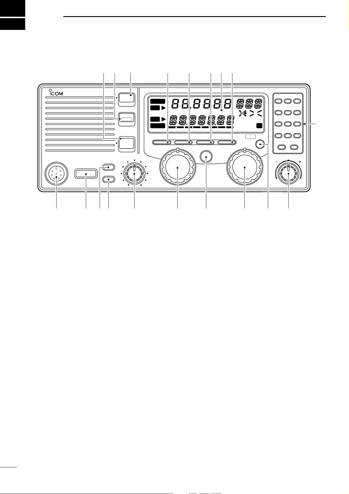
PANEL DESCRIPTION
■ Front panel (controller)
2
q MICROPHONE CONNECTOR (p. 20)
Accepts the supplied microphone or an optional
handset.
☞ NOTE: No audio is output via the speaker when the
microphone or handset is not connected.
w POWER SWITCH [POWER]
Turns power on and off.
e SPEAKER SWITCH [SPEAKER]
Turns the built-in speaker on and off.
•“è” appears in the display while the speaker is turned
off.
• Any external speaker connected to the rear panel is not
turned off.
r DISPLAY INTENSITY SWITCH [DIMMER]
➥ Toggles the display backlight on and off.
➥ While pushing, rotate [CHANNEL] to adjust the
backlighting to one of 4 levels.
➥ While pushing, rotate [GROUP] to adjust the dis-
play contrast to one of 10 levels.
t VOLUME CONTROL [VOLUME]
Adjusts the audio output level.
• Audio does not come from the speaker when:
➟ A microphone is not connected.
➟ The [SQL] switch is turned on and no signal is being
received.
y GROUP CHANNEL SELECTOR [GROUP]
Selects groups in 20 channel steps and ITU marine
channel groups.
☞ NOTE: Some versions have no ITU channels.
u ANTENNA TUNE SWITCH [TUNE] (p. 9)
Tunes the connected tuner to the antenna.
• Activates only when an optional antenna tuner such as
Icom’s AT-130/E is connected.
☞ NOTE: When selecting “automatic tuning” in set
mode, pushing this switch is not necessary to tune
the antenna. (p. 13)
i CHANNEL SELECTOR [CHANNEL] (p. 6)
➥ Selects an operating channel within the selected
channel group such as ITU channels.
• User channels can be selected from 1 to 160 (max.)
in sequence regardless of the channel group.
➥ Changes the operating frequency* after [CE] is
pushed (while “s” appears).
• The changed frequency is not programmed in this
way.
o FUNCTION SWITCH [FUNC]
After pushing, activates the secondary functions of
these switches:
[RESET] . . Deactivates external control such as
from a DSC terminal unit when con-
nected.
[SQL] . . . . . Starts and stops scan (p. 7).
[SPEAKER] Activates intercom function (p. 17).
[RX] . . . . . . Sets RF gain (p. 10).
[TX] . . . . . . Selects transmit power (p. 9).
[CE] . . . . . . Reprograms the channel name (p.
12).
☞ NOTE: Function availability depends on version.
!0 CLARITY CONTROL [CLARITY] (p. 10)
Shifts the receive frequency ±150 Hz for clear reception of an off frequency signal.
Page 7

PANEL DESCRIPTION
0
9
to
–
CH/FREQ
CE
TX
RX
2
!1 KEYPAD
➥ Enters the selected channel number (or fre-
quency*) for direct channel selection. (p. 7)
➥ Stores a receive frequency into a user chan-
nel or ITU simplex channel when:
• pushing [CE] (“s” appears)
• entering the desired frequency via the keypad
• pushing and holding [RX] (p. 12)
➥ Adjusts the RF gain after pushing [FUNC] to
reduce the receiver sensitivity. (p. 10)
➥ Stores a transmit frequency into a user chan-
nel (except General versions) when:
• pushing [TX] (“$” flashes)
• pushing [CE] (“s” appears)
• entering the desired frequency via the keypad
• pushing and holding [TX] (p. 12)
➥ Selects the transmitter channel for cross
channel operation (Europe versions only)
when:
• pushing [TX] (“$” flashes)
• entering the desired channel number via the key-
pad
➥ Selects the transmit output power after push-
ing [FUNC]. (p. 9)
➥ Toggles the channel number input and fre-
quency input.* (p. 8)
•“s” appears when frequency input* is selected.
• The channel selector and keypad changes the
frequency while “s” appears.
➥ Clears the entered digit and retrieves the pre-
vious channel (or frequency*) while entering
numbers. (p. 7)
➥ Enters the name programming condition,
after pushing [FUNC], for changing the channel name. (p. 12)
➥ Toggles the channel and frequency indica-
tions. (p. 6)
➥ Enters “–” for ITU simplex channels. (p. 7)
➥ Enter channel number with up to 4 or 5 digits
when “s” does not appear. (p. 7)
➥ Enter the frequency with up to 6 digits* when
“” appears. (p. 8)
!4 AGC OFF SWITCH [AGC] (p. 10)
Deactivates the AGC function to receive weak signals blocked by strong adjacent signals.
•“ê” appears when the [AGC] switch is turned on
(stands for AGC deactivated).
!5 MODE SWITCH [MODE] (p. 9)
Selects an operating mode temporarily. Available
modes differ with version.
• J3E (USB), H3E, J2B (AFSK), FSK, R3E and A1A (CW)
modes are available.
• The temporary mode is cleared and the previous mode
appears when changing a channel.
!6 OVEN INDICATOR (GMDSS version only)
Internal high-stability crystal oscillator unit contains
a temperature-compensating oven heater. This
high-stability crystal oscillator improves frequency
stability.
•“STANDBY” appears when power to the main unit is
turned off.
!7 TRANSMIT FREQUENCY SWITCH [TX FREQ]
(p. 9)
Displays the transmit frequency and opens the
squelch to check and monitor the transmit frequency.
!8 2182 kHz SELECTION SWITCH
[2182kHz •
RESET
] (p. iii)
➥ Selects channel 0 (2182 kHz; distress call fre-
quency).
• The channel selector does not function when selecting channel 0.
➥ Ignores external control and gives the front panel
control priority when an external controller
(NMEA format) is connected.
!9 ALARM SWITCH [ALARM] (p. iii)
➥ Emits a distress alarm signal from the speaker.
➥ Transmits a distress alarm or alarm testing signal
when pushed together with the [TX FREQ]
switch.
☞ NOTE: General versions are not equipped with this
[ALARM] switch.
!2 SQUELCH SWITCH [SQL] (p. 10)
➥ Activates the voice squelch function to reject un-
desired background noise while no signal is
being received.
• The squelch opens only when the received signal
contains no voice or FSK components.
➥ Starts and stops the scan function after pushing
[FUNC]. (p. 7)
!3 NOISE BLANKER SWITCH [NB] (p. 10)
Turns the noise blanker function on to remove
pulse-type noise such as engine ignition noise.
•“NB” appears when the function is turned on.
*Some versions do not have frequency selection and fre-
quency indication.
3
Page 8
2
q
t
w er
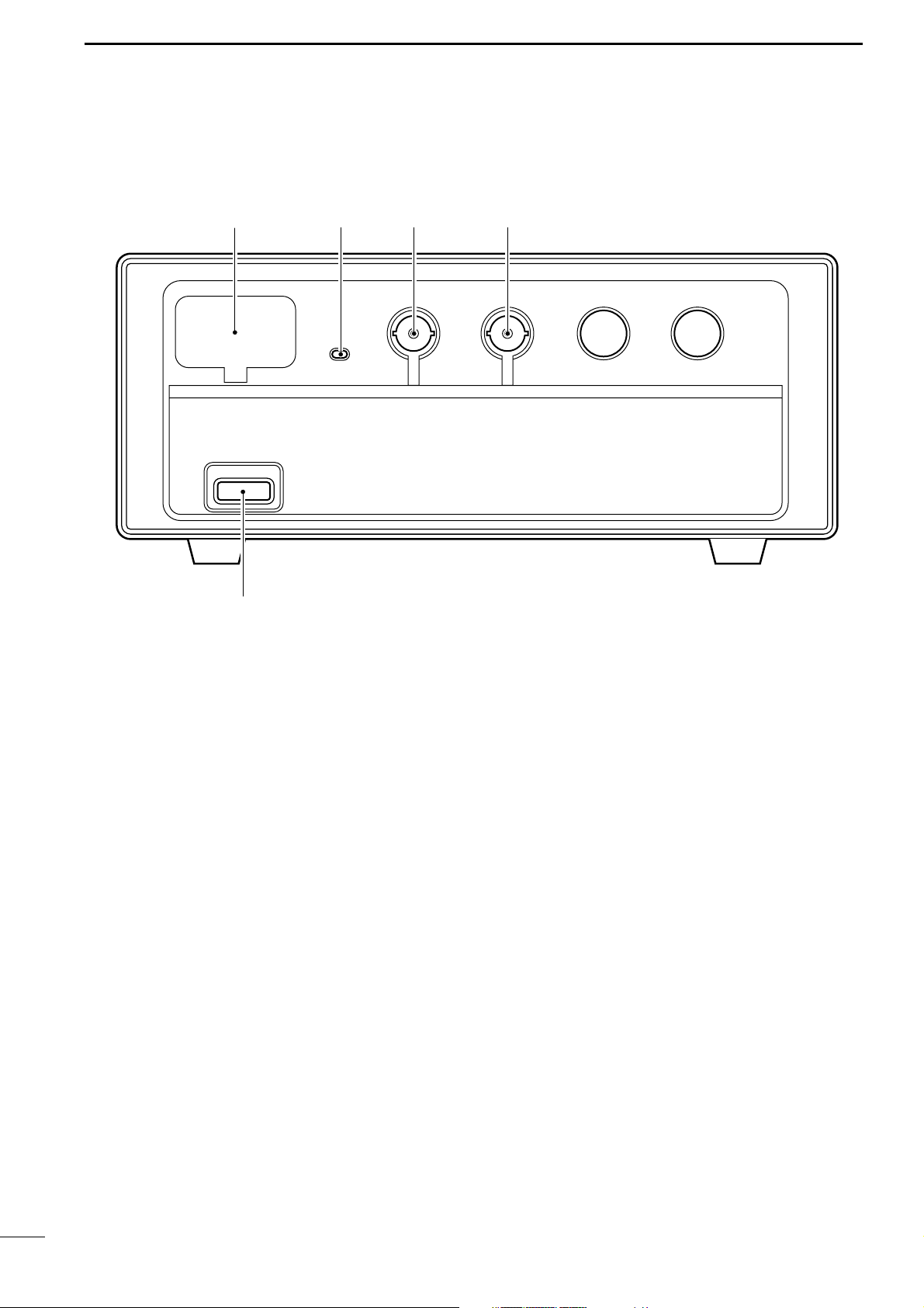
PANEL DESCRIPTION
■ Main unit (controller detached)
q RS-232C CONNECTOR (p. 18)
Connects the IC-M710RT to a PC via an RS-232C
cable for remote control of transceiver function
using the optional RS-710RT software.
w POWER INDICATOR
Appears while power is turned on.
e CONTROLLER CONNECTOR
Connects the main body of the IC-M710RT to the
front panel (controller) when detached from the
main body.
r CONTROLLER CONNECTOR (pgs. 16, 17)
Same as above.
t POWER SWITCH
Same function as the power switch ([POWER]) on
the front panel.
• Only available on the Europe and GMDSS versions.
D HM-120 microphone keys
The “P” key on the HM-120
set to function as the [MODE], [NB], [AGC], [SQL] or
[TUNE] keys on the remote controller. (The YZ keys
function the same as the [CHANNEL] selector). Also,
using set mode (p. 15) these keys can be deactivated
if desired.
While pushing [P] on the microphone and the switch
on the remote controller whose function you want to
assign (see above), turn power ON.
• Repeat this to assign a different key.
HAND MICROPHONE
can be
4
Page 9
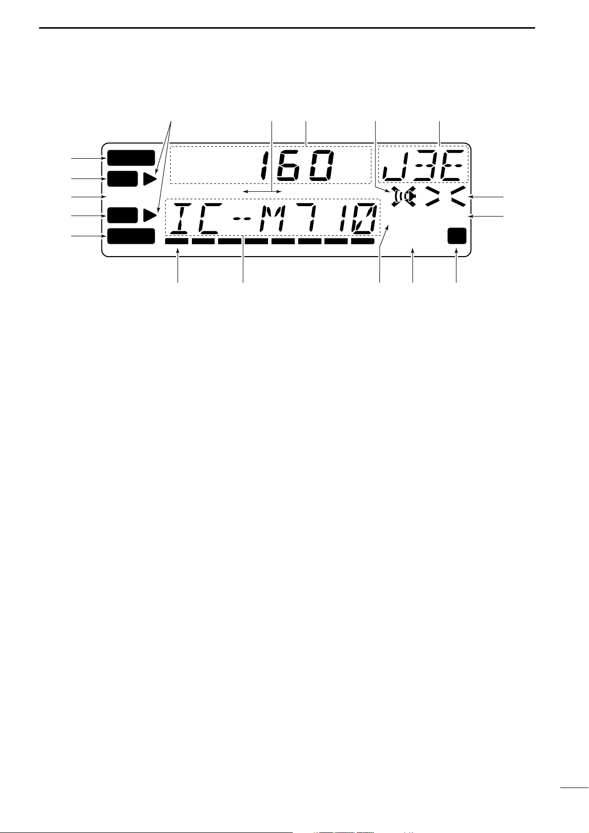
■ Display
TUNE
DUP SIMP
TX
RX
DSC
FSCAN
SQL N B
AGC
AGC
A43210
ALM
q
w
e
r
t
yu io!0
!1
!2
!3!4!5!6!7
PANEL DESCRIPTION
2
q ALARM INDICATOR (p. iii)
Appears when the alarm function is activated such
as for an alarm test or distress alarm transmission.
• Not available in General version.
w RECEIVE INDICATOR (p. 10)
Appears while receiving and when the squelch is
open.
e TUNE INDICATOR (p. 9)
Flashes while the connected antenna tuner, such as
Icom’s AT-130, is being tuned.
• Tuning starts when transmitting on a new frequency or
pushing the [TUNE] switch.
r TRANSMIT INDICATOR
➥ Appears when transmitting. (p. 9)
➥ Flashes when the [TX] key is pushed for transmit
frequency programming. (p. 12)
t DSC INDICATOR (p. iii)
Appears when an optional GM-110DSC
NAL UNIT
• The GM-110DSC can be connected to GMDSS versions
only.
y S/RF METER
➥ Shows the relative received signal strength while
➥ Shows output power while transmitting.
➥ Shows antenna current level when an optional
u CHANNEL/VFO INDICATOR
➥ Shows the pre-programmed channel name (al-
➥ Shows the transmit frequency during frequency
➥ Shows transmit channel number during cross
controls transceiver functions.
receiving.
AT-130E
versions only).
HF ANTENNA TUNER
is connected (Europe
phanumeric) during channel indication. (p. 6)
• Some versions have no channel name function and
show receive frequency instead.
indication. (p. 6)
channel operation (Europe versions only). (p. 11)
DSC TERMI
i SQUELCH INDICATOR (p. 10)
Appears when the squelch is on.
o SCAN INDICATOR (p. 7)
Appears when the scan function is in use.
• The scan function is not available on some versions.
• Pushing [FUNC] then [SQL] starts and stops scan.
!0 FUNCTION INDICATOR
Appears when the [FUNC] switch is pushed.
!1 NOISE BLANKER INDICATOR (p. 10)
Appears when the [NB] switch is turned on.
!2 AGC OFF INDICATOR (p. 10)
Appears when the [AGC] switch is pushed to indicate the AGC function is deactivated.
!3 MODE READOUT
Shows the selected operating mode (type of emission).
-
!4 SPEAKER OFF INDICATOR
Appears when the [SPEAKER] switch is pushed to
indicate the front panel speaker is deactivated.
!5 CHANNEL READOUT
➥ Shows the selected channel number during
channel indication. (p. 6)
➥ Shows the receive frequency during frequency in-
dication. (p. 9)
!6 SIMPLEX/DUPLEX INDICATORS
These appear to show whether the selected channel is simplex or duplex.
!7 FREQUENCY INDICATORS (p. 8)
Appear when the frequency entry condition* is selected for frequency selection.
• The [CE] key toggles the indicator ON and OFF.
* Some versions have no frequency entry condition.
5
Page 10
3
DUP
TX
RX
DSC
F
AGC
ALM
DUP
TX
RX
DSC
F
AGC
ALM
DUP
TX
RX
DSC
F
AGC
ALM
DUP
TX
RX
DSC
F
AGC
ALM
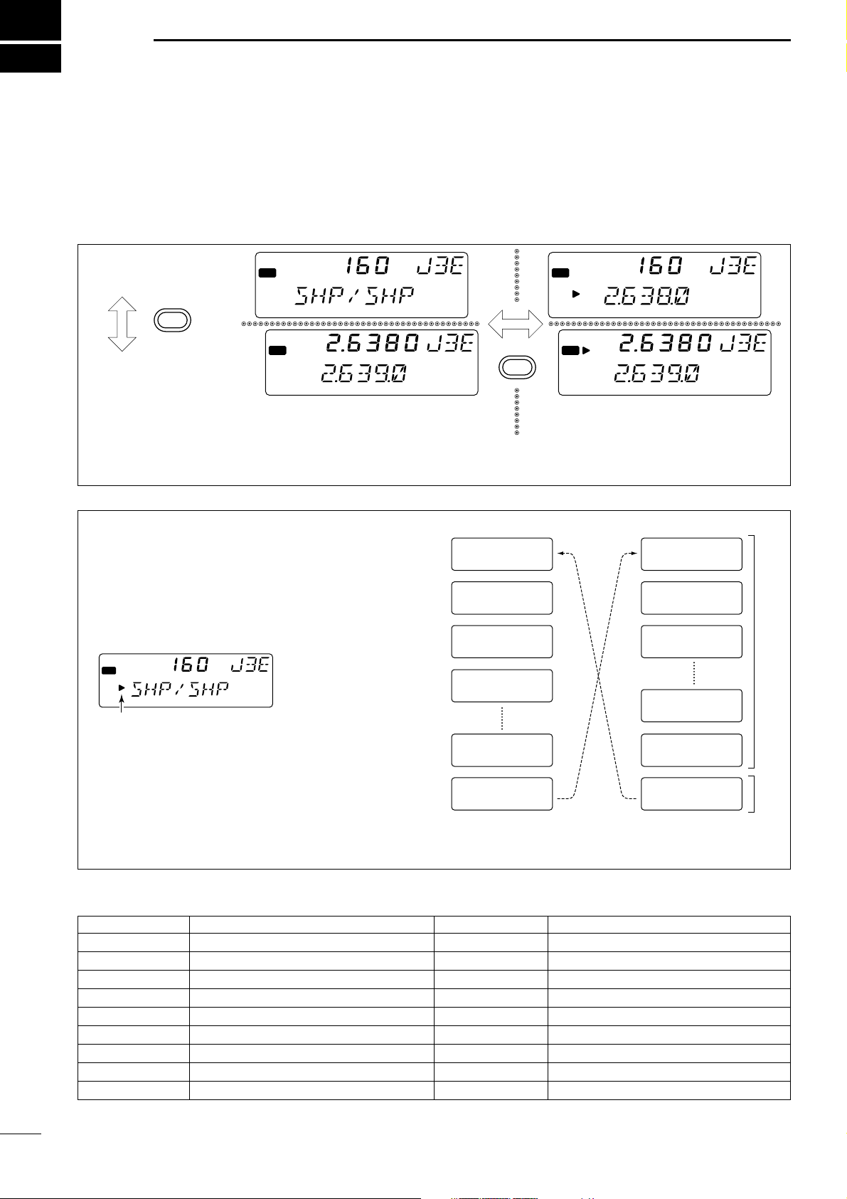
CHANNEL INDICATION
FREQUENCY INDICATION
CHANNEL SELECTION MODE
Channel can be selected
FREQUENCY SELECTION MODE
Frequency can be changed
CH/FREQ
CE
AGC
SELECTING A CHANNEL/FREQUENCY
■ Selecting a channel
The transceiver has 160 user channels and ITU channels. However, the number of user channels can be
optionally restricted and ITU channels are not available
with some versions.
☞ NOTE: Channel name (alphanumeric) may not
appear during channel indication depending on
set mode settings (p. 14).
D Using the channel selector
The transceiver has two large controls for group selection and channel selection. The [GROUP] selector
changes channels in 20 channel increments and selects ITU channel groups*; and the [CHANNEL] selector selects each channel.
➀ Make sure no “s” indicator appears on the display.
ALM
RX
TX
DSC
➁ Rotate the [GROUP] selector to select the desired
channel group as shown at right and/or below.
➂ Rotate the [CHANNEL] selector to select the de-
sired channel.
DUP
F
If appears, push [CE] to delete it.
☞ NOTE: When channel 0 and/or 2182 kHz is se-
lected with the [2182KHz] switch, channel selection
is NOT possible. In such cases, push [2182KHz] in
advance.
[EXAMPLE]: Selection with the [GROUP] selector
1 J3E
WWV
21 J3E
KMI
41 J3E
WOM
61 J3E
WOO
121 J3E
FAX
141 J3E
SHP/SHP
401 J3E
4.357.0
4-1 J3E
4A LTD
601 J3E
6.501.0
2501 J3E
26.145.0
25-1 J3E
FAX
4001 FSK
4.210.5
ITU SSB channels*
ITU FSK
channels*
CHANNEL GROUPS
CHANNEL NO. DESCRIPTION
1 to 160 User channels*
401 to 427 4 MHz ITU duplex channels
4-1 to 4-9 4 MHz ITU simplex channels
6
601 to 608 6 MHz ITU duplex channels
6-1 to 6-9 6 MHz ITU simplex channels
801 to 832 8 MHz ITU duplex channels
8-1 to 8-9 8 MHz ITU simplex channels
1201 to 1241 12 MHz ITU duplex channels
12-1 to 12-9 12 MHz ITU simplex channels
*1[GROUP] selector changes in 20 channels steps.
*2SITOR use—no group separation.
1
*All ITU channels are not available with some versions and ITU
FSK channels can be hidden using set mode. (p. 13)
CHANNEL NO. DESCRIPTION
1601to 1656 16 MHz ITU duplex channels
16-1 to 16-9 16 MHz ITU simplex channels
1801 to 1815 18 MHz ITU duplex channels
18-1 to 18-9 18 MHz ITU simplex channels
2201 to 2253 22 MHz ITU duplex channels
22-1 to 22-9 22 MHz ITU simplex channels
25-1 to 25-9 25 MHz ITU simplex channels
4001 to 25040 ITU FSK duplex channels*
2
2501 to 2510 25 MHz ITU duplex channels
Page 11

SELECTING A CHANNEL/FREQUENCY
AGC
AGC
AGC
AGC
AGC
3
D Using the keypad
Direct channel selection via the keypad is available
for quick channel selection.
➀ Make sure “s” does not appear on the display.
• If it appears, push [CE] to delete it.
➁ Enter the desired channel number via the keypad.
• A user channel is selected when channel 1–160 is input
(max. number may be optionally restricted).
• An ITU SSB channel is selected when channel numbers higher than 401 are input (not available for some
versions).
• An ITU FSK channel is selected when channel numbers
higher than 4001 are input (not usable according to set
mode setting).
• The “–” key can be used for selecting an ITU simplex
channel.
➂ Push [RX] to select the entered channel.
D Using scan functions
(Some versions do not have these functions)
The transceiver has automatic channel or frequency
change capability (scan function). There are 3 types
of scan functions available to suit your needs.
Channel scan
[EXAMPLE]: Selecting channel 153
ALM
RX
RX
1
5
3
TX
DSC
ALM
RX
TX
DSC
ALM
RX
TX
DSC
ALM
RX
TX
DSC
ALM
RX
TX
DSC
DUP
F
DUP
F
DUP
F
DUP
F
DUP
F
Channel scan and channel resume scan increase
channels within a 5 channel range such as ch 1 to ch
5, ch 156 to ch 160, etc. in user channels; or all channels in the group of ITU channels.
Programmed scan (optional) changes frequencies
within the frequency range between user channels
159 and 160.
ch 2 ch 3
ch 1
ch 5
Channel resume scan
ch 2 ch 3
ch 1
ch 5
Programmed scan (optional)
ch 159 ch 160
scan is
cancelled
ch 4
when
transmitting
scan pauses
for 30 sec.,
ch 4
then resumes
after
transmitting
Scans the frequency range
between the programmed
frqeuencies on channels
159 and 160.
Scans fast when squelch is
closed and slowly when
squelch is open.
Scan selection is available in set mode. See p. 14 for
scan selection.
SCAN OPERATION
➀ Select your desired channel group with the
[GROUP] and [CHANNEL] selector.
• Or use the keypad and [CE] key for direct selection.
• This operation is not necessary for programmed scan.
➁ Push [SQL] to turn OFF the squelch function if pro-
grammed scan is selected.
➂ Push [FUNC] then [SQL] to start the scan.
➃ To stop the scan, repeat step ➂ again.
• [CHANNEL] rotation and some other switches also stop
the scan.
7
Page 12

3
AGC
DUP
TX
RX
DSC
F
AGC
ALM
DUP
TX
RX
DSC
F
AGC
ALM
No “≈” indicator shows that the channel will
be changed when rotating [CHANNEL].
“≈” and frequency show that the frequency
will be changed.
CE
TX
RX
DSC
F
AGC
ALM
TX
RX
DSC
F
AGC
ALM
TX
RX
DSC
F
AGC
ALM
TX
RX
DSC
F
AGC
ALM
TX
RX
DSC
F
AGC
ALM
TX
RX
DSC
F
AGC
ALM
TX
RX
DSC
F
AGC
ALM
Select non frqeuency
programmed channel.
After temporarily receiving.
1
5
3
RX
2
4
0
CE
CE
(momentarily)
SELECTING A CHANNEL/FREQUENCY
■ Selecting a frequency
The transceiver has 0.5 to 30.0 MHz general coverage
receive capability with 100 Hz resolution. The receive
frequency can be changed instantly, independent of
the transmit frequency.
D Using the channel selector
➀
Select a channel which is programmed near the
frequency you want to receive.
➁ Push the [CE] key to select frequency selection
mode.
•“s” appears on the display.
➂ Rotate the [CHANNEL] selector to change the fre-
quency.
➃ To return to the previous frequency, push [CE].
•“s” disappears and the previous frequency or channel
name appears.
☞ NOTE: The selected frequency is used for tempo-
rary receiving (transmitting is not available). This
frequency is cleared once the channel is changed.
If you want to program a frequency, refer to p. 12.
D Using the keypad
☞ CAUTION: A frequency can be entered into a
user channel or ITU simplex channel by pushing
the [RX] key. However, when pushing and holding the [RX] key after entering a frequency, the
previously programmed contents are erased and
cannot be retrieved. Therefore, keypad entry
should be used only on spare channels.
8
➀ Select the memory channel to be used for general
coverage use.
ALM
RX
TX
DSC
No frqeuency programmed channel for general
coverage use.
(mode and channel name do not appear)
➁ Push [CE] to select frequency selection mode.
➂ Enter the desired frequency with 5 or 6 digits.
➃ Push [RX] to input the frequency.
• Do not hold [RX] for more than 0.5 sec., otherwise the
frequency will be programmed into the channel.
[EXAMPLE]: Setting 12.3450 MHz
F
Page 13

RECEIVE AND TRANSMIT
microphone
connector
[SQL]
[SPEAKER] [CLARITY]
AGC
■ Basic voice receive and transmit
4
➀ Check the following in advance:
➥ Microphone is connected.
➥ [SPEAKER] switch is turned off.
➥ [SQL] switch is turned off.
➥ [CLARITY] control is set to the center position.
➁ Select the desired channel to be received with the
[GROUP] and [CHANNEL] selectors.
• When receiving a signal, the S-meter shows the signal
strength.
■ Functions for transmit
➂ Adjust [VOLUME] to the desired audio level when
receiving a signal.
➃ Push [MODE] to select the desired operating mode,
if the received signal is in a different mode.
➄ Push [TUNE] to tune the antenna tuner, if con-
nected.
• This operation is not necessary when “automatic tuning”
is selected in set mode (p. 13).
➅ To transmit on the channel, push and hold the PTT
switch on the microphone.
•“TUNE” flashes for 1 to 2 sec. for the first transmission
on a channel when an antenna tuner is connected.
➆ After the flashing stops, speak into the microphone
at your normal voice level.
• The RF meter shows the output power according to your
voice level.
➇ Release the PTT switch to return to receive.
D Transmit frequency check
When “DUP” appears on the display such as for a
ship-to-shore channel, the transmit frequency differs
from the receive frequency.
In such cases, the transmit frequency should be monitored before transmitting to prevent interference to
other stations.
D Transmit power selection
The transceiver has 3 selectable output powers.*
High power allows longer distance communications
and low power reduces power consumption.
*Only 2 selectable output powers are available with some
versions. In this case, level 1 stands for 60 W (the same as
level 2).
☞ NOTE: Low power setting affects all channels ex-
cept the 2182 kHz emergency channel.
☞ NOTE: Although power selection appears possi-
ble with GMDSS versions, only high power is
available.
Push and hold [TX FREQ] to monitor the transmit frequency.
TX FREQ
• The display shows the transmit frequency.
➀ Push [FUNC] then [TX] to call up the following dis-
play.
ALM
RX
TX
DSC
F
➁ Rotate the [CHANNEL] selector to select high or
low output power.
3 : high power (150 W PEP)
2 : middle power (60 W PEP)
1 : low power (20 W PEP)
➂ Push [FUNC] or [CE] to return to the previous dis-
play.
9
Page 14

4
AGC
AGC
AG
AGC
RECEIVE AND TRANSMIT
■ Functions for receive
D Squelch function
The squelch function detects signals with voice components and squelches (mutes) unwanted signals
such as unmodulated beat signals. This provides
quiet standby.
When you need to receive weak signals, the squelch
should be turned off.
D Noise blanker
The noise blanker function reduces pulse type noise
such as that coming from engine ignitions.
The noise blanker may distort reception of strong signals. In such cases, the noise blanker should be
turned off.
Push [SQL] to toggle the function on and off.
ALM
RX
TX
DSC
DUP
SQL
F
•“SQL” appears when the squelch function is turned on.
Push [NB] to toggle the function on and off.
ALM
RX
TX
DSC
•“NB” appears when the noise blanker function is turned
on.
DUP
NB
F
D AGC off function
The receiver gain is automatically adjusted according
to received signal strength with the AGC (Automatic
Gain Control) function to prevent distortion from
strong signals and to obtain a constant output level.
When receiving weak signals with adjacent strong
signals or noise, the AGC function may reduce the
sensitivity. In this situation, the AGC function should
be deactivated.
D RF gain setting
The receiver gain can be reduced with the RF gain
setting. This may help to remove undesired weak signals while monitoring strong signals.
Usually, the AGC function reduces the RF gain according to the receive signal strength and these weak
signals are remove. However, during no signal reception, these weak signals may not be heard.
In such cases, the RF gain may be useful for setting a
minimum level at which to hear signals.
Push [AGC] to toggle the function on and off.
ALM
RX
TX
DSC
AGC
AG
C
F
•“ê” appears when the AGC function is deactivated.
➀ Push [FUNC] then [RX] to call up the following dis-
play.
ALM
RX
TX
DSC
F
➁ Rotate the [CHANNEL] selector to set the desired
minimum cutting level.
•“0” to “9” are available.
• S-meter shows the minimum permitted level.
➂ Push [FUNC] or [CE] to exit the RF gain display.
10
D Clarity control
Voice signals received from other stations may be difficult to receive. This may sometimes happen if a station is transmitting slightly off frequency. In such
cases, compensate the receive frequency only, using
the [CLARITY] control.
Adjust [CLARITY] to improve the audio signal.
[CLARITY]
Page 15

■ CW operation
AGC
AGC
RECEIVE AND TRANSMIT
4
The transceiver has the following CW keying features
selectable in set mode as described on page 15.
➥ Full break-in (receiving is possible while transmitting)
➥ Delay keying (automatic transmission with keying)
➥ Off (manual transmission is necessary before keying)
➀ Connect a CW keyer or an external electronic
keyer to the ACC(1) socket as shown at right.
➁ Select the desired channel to operate CW mode.
➂ When the selected channel is not in A1A mode,
push [MODE] one or more times to select “A1A.”
➃ Operate the CW keyer to transmit a CW signal.
☞ NOTE: CW mode is not available in some ver-
sions and CW narrow can be selected in set mode
(p. 14) when an optional filter is installed (already
built-in to the GMDSS versions).
■ FSK operation
The transceiver has FSK and J2B modes for FSK operation—use FSK when using the built-in oscillator;
use J2B when using an AFSK terminal unit.
CW key connection
2
4
1
8
6
ACC(1) socket
pin 2
5
3
pin 1
7
FSK terminal unit connection
CW key
➀ Connect an FSK terminal unit as shown at right.
➁ Select the desired channel.
• FSK ITU channel group, ch 4001 to ch 25040, are available depending on version.
➂ Push [MODE] one or more times to select the type
of emission, “FSK” or “J2B.”
➃ Operate the FSK terminal unit.
☞ NOTE:
➥ FSK shift frequency and FSK polarity can be
adjusted in set mode (p. 14).
➥ Some transceivers my operate 1.7 kHz higher
than the IC-M710RT’s J2B mode even when
the same displayed frequencies are in use.
■ Cross channel operation*
Cross channel operation is available with some versions to operate different channels for receive and
transmit.
➀ Select the desired channel for receive.
• ITU simplex channels cannot be used.
➁ Push [TX], then select the desired channel for
transmit.
•“$” flashes after pushing [TX].
➂ Push [TX] again to stop the blinking.
➃ Operate the transceiver normally.
➄ Change the channel to clear the cross channel set-
ting.
*This function is available for Europe versions only.
pin 4
2
4
5
1
3
8
6
7
ACC(1) socket
pins 2, 5
pin 3
FSK keying
AF input
Tx/Rx control
Ground
FSK terminal unit
Cross channel operation example
ALM
RX
TX
DSC
While receiving
DUP
ALM
RX
TX
DSC
While transmitting
DUP
F
A43210
F
A43210
11
Page 16

5
AGC
AGC
AGC
AGC
AGC
AGC
AGC
AGC
AGC
USER CHANNEL PROGRAMMING
■ Programming a frequency
The IC-M710RT has up to 160 user-programmable
channels each with channel name capability of up to 7
alphanumeric characters.
D Receive frequency
➀
Select the desired channel to be programmed.
• Channels 1 to 160 (maximum) are programmable.
➁ Push [CE] to select frequency selection mode.
•“s” and frequency appear on the display.
➂ Enter the desired frequency via the keypad—5 or
6 digits.
• Or rotate the [CHANNEL] selector to change the frequency.
➃ To change the operating mode (type of emission),
push [MODE] one or more times.
➄ Push and hold [RX] for 1 sec. to program the user
channel.
D Transmit frequency
(Not applicable for General versions)
➀ Select the desired user channel to be programmed.
➁ Push [TX].
•“$” flashes.
➂ Push [CE] to select frequency selection mode.
•“s” and frequency appear on the display.
➃ Enter the desired frequency via the keypad with 5
or 6 digits.
• The [CHANNEL] selector cannot be used.
➄ Push and hold [TX] for 1 sec. to program.
➅ Push [TX] to stop “$” from flashing.
☞ NOTE: ITU simplex channels can be programmed
as well as user channels. However, transmit frequencies cannot be programmed as it is not necessary.
Push [CE]
Set frequency
Push and hold [RX]
Push [TX]
Push [CE]
Push and hold [TX]
after entering a
frqeuency
ALM
RX
TX
DSC
DUP
F
Frequency and “≈” appear.
ALM
RX
TX
DSC
DUP
F
Use keypad or channel selector.
ALM
RX
TX
DSC
DUP
F
Programming is completed.
ALM
RX
TX
DSC
DUP
F
“$” flashes.
ALM
RX
TX
DSC
ALM
RX
TX
DSC
DUP
F
DUP
F
12
D Channel names
➀
Select the desired user channel to be programmed.
➁ Push [CH/FREQ] to select channel indication.
➂ Push [FUNC] then [CE].
• The channel name (alphanumeric) readout flashes.
➃ Rotate the [GROUP] selector for cursor position
and the [CHANNEL] selector for name content.
• To return to the previous message, push [CE].
➄ Push and hold [RX] to program the name.
• Flashing stops.
Push [FUNC]
then [CE]
Rotate [GROUP]
and [CHANNEL]
to select cursor and
character
Push [RX]
ALM
RX
TX
DSC
DUP
“$” flashes.
ALM
RX
TX
DSC
ALM
RX
TX
DSC
DUP
DUP
F
F
F
Page 17

■ Set mode operation
TX
RX
DSC
F
AGC
ALM
[POWER] [FUNC] [1]
Condition
Item
AGC
AGC
Set mode operation is used for programming infrequently changed values or conditions of functions.
✍ NOTE: Some of the set mode items described in
this section are not available on some transceiver
versions.
➀ Push [POWER] to turn power off, if necessary.
➁ While pushing [FUNC] + [1], push [POWER] to turn
power on and enter set mode.
➂ Rotate the [GROUP] selector to select the desired
item.
➃ Rotate the [CHANNEL] selector to set the values or
conditions for the selected item.
➄ Turn power off and on again to exit set mode.
■ Set mode contents
(1) FSK ITU channels
FSK ITU channels appear as a group between the
ITU 25 MHz band and user channels. This FSK channel group can be hidden for voice communication
only.
SET MODE
FSK channels don’t appear
(no SITOR operation).
(default)
FSK channels appear (for
SITOR operation).
6
(2) Connected antenna tuner
The transceiver has several tuner control systems for
use with an optional Icom antenna tuner. Select the
condition depending on the connected antenna tuner.
☞ NOTE: Internal switch selection may be required
when using a non-Icom tuner (p. 23).
(3) Automatic tuning condition
When the optional AT-130 or AT-130E automatic antenna tuner is connected, tuning can be started automatically without the [TUNE] switch, for instant
operation.
If manual tuning is required, this automatic operation
can be deactivated.
ALM
RX
TX
DSC
ALM
RX
TX
DSC
AT-130
(default)
AT-120
AH-3
Tuning starts when pushing
[PTT] on a new frqeuency.
F
Tuning starts only when
[TUNE] is pushed.
(default)
F
13
Page 18

6
AGC
AGC
Channel number
and channel name
—alphanumeric
(default)
Channel number
and frequency
AGC
AGC
AGC
AGC
AGC
SET MODE
(4) Scan type selection (scan-type only)
This item selects one of the following scan functions.
Channel scan and channel resume scan search 5
channels around a user selected channel or search
all ITU channels in the band when an ITU channel is
selected.
Programmed scan (optional) searches signals within
the frequency range and activates slowly while
squelch is open and fast while squelch is closed.
ALM
RX
TX
DSC
ALM
RX
TX
DSC
ALM
RX
TX
DSC
Channel scan
Scan is canceled when
transmitting.
F
(default)
Channel resume scan
Scan pauses when squelch
opens, then resumes after
F
10 sec.
Channel resume scan
Scan operates over the frequency range.
F
(optional)
(5) Scan speed
This item adjusts the scan speed (rate at which channels are searched). The scan speed can be set from
1 to 10 with “1” being the fastest and “10” being the
slowest.
(6) Channel name and frequency
The lower half of the display can be set to display a
programmable channel name or a receive frequency
according to operator needs.
(7) CW/FSK narrow filter
This item selects the passband width for A1A (CW),
FSK or J2B mode.
✍ NOTE: When “on” is selected without optional fil-
ter installation, the Marine and General versions
do not function in these modes. The GMDSS versions can use “on” as standard.
ALM
RX
TX
DSC
ALM
RX
TX
DSC
ALM
RX
TX
DSC
ALM
RX
TX
DSC
Fastest scan speed
F
(default: 4)
Slowest scan speed
F
Passband:
2.3 kHz/–6 dB
(default)
F
Passband:
500 Hz/–6 dB (Gene/Marine)
350 Hz/–6 dB (GMDSS)
F
14
(8) FSK shift frequency
Several shift frequencies (the difference between the
mark and space frequency) are used for FSK operation. This item allows you to select a shift frequency
for almost any FSK system.
Shift frequency:
170 Hz
(default)
Shift frequency:
425 Hz
Shift frequency:
850 Hz
Page 19

SET MODE
AGC
AGC
AGC
AGC
AGC
AGC
6
(9) FSK polarity
Normal and reverse polarities are available for FSK
operation. This item allows you to select one of these
polarities.
“FSK-REV off” (normal):
key open (mark); key close (space)
“FSK-REV on” (reverse):
key open (space); key close (mark)
(10) CW break-in
The CW break-in function (in A1A mode) toggles
transmit and receive with CW keying. Full break-in allows you to receive signals between transmitted keying pulses during CW transmission. Semi break-in
allows you to mute receiving until keying stops with
some delay time.
FSK normal
(default)
FSK reverse
Full break-in
Automatic keying without
delay time
(default)
Semi break-in
Automatic keying with delay
time
OFF
Manual transmission
necessary for keying
(11) Microphone keys
This item activates/deactivates the keys on the HM120
HAND MICROPHONE
(“P”, “Y” and “Z”). Refer to
p. 4 to program the “P” key.
(12) Remote control busy timer
This sets the time for which operation of one remote
controller is inhibited while operating the other. The
timer can be set from 0 to 180 sec.
(13) ID number setting for remote control
When connecting an external controller such as a
personal computer, 2-digit ID codes are required to
access the transceiver. The IC-M701RT adopts
NMEA0183 format and uses a “proprietary sentence”
for remote control. ID 01 to 99 are available.
ALM
RX
TX
DSC
ALM
RX
TX
DSC
ALM
RX
TX
DSC
ALM
RX
TX
DSC
Microphone keys
activated.
(default)
F
Microphone keys
deactivated.
F
Busy timer: 5 sec.
(default)
F
NMEA ID: 03
(default)
F
(14) Remote control input terminal
Remote control signals can be input via the [RS232C] socket or [CLONE] jack.
ALM
RX
TX
DSC
ALM
RX
TX
DSC
[REMOTE] socket
(default)
F
[CLONE] jack
F
15
Page 20

7
CONNECTIONS AND INSTALLATION
■ Supplied accessories
DC power cable (OPC-568) . . . . . . . . . . . . . . . . . 1
Mounting bracket . . . . . . . . . . . . . . . . . . . . . . . . . . 1
Bracket knobs (8820000170) . . . . . . . . . . . . . . . . 4
CONNECTORS
DIN connector (8-pin for ACC1) . . . . . . . . . . . . . . 1
DIN connector (7-pin for ACC2) . . . . . . . . . . . . . . 1
Tuner connector (56100000150) . . . . . . . . . . . . . . 1
Pins for tuner connector (6510019030) . . . . . . . . . 4
DIN connector cover (GMDSS only—attach to the
ACC sockets) . . . . . . . . . . . . 1
NUTS AND BOLTS
Allen bolt (M6 × 50) . . . . . . . . . . . . . . . . . . . . . . . . 4
Self-tapping screws (M6 × 30) . . . . . . . . . . . . . . . . 4
Nuts (M6; use 2 pcs. for each bolt) . . . . . . . . . . . . 8
Flat washers (M6) . . . . . . . . . . . . . . . . . . . . . . . . . 8
Spring washers (M6) . . . . . . . . . . . . . . . . . . . . . . . 4
Self-tapping screws
(3.5 × 30 for mic. hanger) . . . . . . . . . . . . . . . . 2
FUSES
FGB 30 A (rear panel) . . . . . . . . . . . . . . . . . . . . . . 2
FGB 5 A (internal) . . . . . . . . . . . . . . . . . . . . . . . . . 2
RC-21 (REMOTE CONTROLLER) ACCESSORIES
Microphone (HM-120*) . . . . . . . . . . . . . . . . . . . . . 1
Microphone hanger* . . . . . . . . . . . . . . . . . . . . . . . 1
DC power cable (OPC-775) . . . . . . . . . . . . . . . . . 1
Mounting bracket . . . . . . . . . . . . . . . . . . . . . . . . . . 1
Bracket knobs . . . . . . . . . . . . . . . . . . . . . . . . . . . . 2
NUTS AND BOLTS
Self-tapping screws*
(3.5 × 30 for mic. hanger) . . . . . . . . . . . . . . . . 2
Flat washers (M5) . . . . . . . . . . . . . . . . . . . . . . . . . 2
Nuts (M6; use 2 pcs. for each bolt) . . . . . . . . . . . 10
Spring washers (M6) . . . . . . . . . . . . . . . . . . . . . . . 5
Allen bolt (M6 × 50) . . . . . . . . . . . . . . . . . . . . . . . . 5
Self-tapping screws . . . . . . . . . . . . . . . . . . . . . . . . 5
Flat washers (M6) . . . . . . . . . . . . . . . . . . . . . . . . 10
Ground lug (M5) . . . . . . . . . . . . . . . . . . . . . . . . . . 1
FUSES
FGB 30 A (rear panel) . . . . . . . . . . . . . . . . . . . . . . 2
FGB 5 A (internal) . . . . . . . . . . . . . . . . . . . . . . . . . 2
*Depends on version.
■ Attaching 1 remote controller
16
Page 21

CONNECTIONS AND INSTALLATION
Controller
Controller
DC 13.6 V
DC 13.6 V
DC 13.6 V
IC-M710RT
main unit
7
■ Attaching 2 remote controllers
D Set ID number
The ID numbers for each remote controller must be set
properly for the intercom function to operate (see
right).
➀ While pushing [FUNC] + [–], push [POWER].
• Channels 1 to 160 (maximum) are programmable.
➁ Rotate the channel selector to select the desired
unit ID number if desired.
• Default ID’s are No. 1 for the supplied remote controller
and No. 2 for an optional remote controller.
➂ Push [POWER] turn the power OFF.
D Intercom operation
The intercom function allows you to communicate between two remote controllers.
➀ Push [FUNC] and then push [SPEAKER] to turn the
intercom function ON.
•“INCOM” blinks and beeps are emitted; the blinking con-
tinues until the intercom function is cancelled.
• Push [FUNC] to cancel the intercom function.
➁ Push and hold the [PTT] switch on the microphone
and speak into the microphone at a normal voice
level.
• The display stops blinking and the ID number of the remote controller being used to transmit appears on both
remote controller displays.
• When no ID appears, operators at either remote controller are free to transmit.
• When neither remote controller is used to transmit for 30
sec. the intercom function is automatically cancelled.
➂ Push [FUNC] to end intercom operation.
17
Page 22

7
Controller
Controller
13.6 V DC
DC 13.6 V
Personal computer
IC-M710RT
main unit
CONNECTIONS AND INSTALLATION
■ Attaching 2 remote controllers and a PC
18
■ Notes for remote control
☞ When more than 1 controller (incl. PC) is con-
nected, the controller (or PC) being operated at
any given time has priority.
☞ When more than 1 controller (incl. PC) is con-
nected, the controller (or PC) not being operated is
inhibited for a specified time after another controller (or PC) is operated. This time can be programmed by your dealer. The default inhibit time is
5 sec.
☞ When more than 1 controller (incl. PC) is con-
nected, operating one controller automatically updates settings on the other controller (PC).
☞ Volume adjustment is independently controlled by
each remote controller (PC).
☞ The optional RS-M710RT software allows you to
program memory channels not available through
regular IC-M710RT operation. Refer to the RSM710RT online help for details.
➣ CAUTION: The rear of any connected remote
controller must be properly grounded. We suggest
using a wide copper ribbon. (p. 22)
Page 23

CONNECTIONS AND INSTALLATION
q
w
r
t
y
u
i
oe
Optional AT-130
12 V battery
7
■ Connections on rear panel
q ANTENNA CONNECTOR (p. 23)
Connects a 50 Ω HF band antenna with a 50 Ω
matched coaxial cable and a PL-259 plug.
w GROUND TERMINAL
IMPORTANT! Connects a ship’s (or vehicle’s)
ground. See p. 22 for details.
e ACC(1) and ACC(2) SOCKETS
See p. 20 for details.
r CLONE JACK
For Dealer use only.
t DSC or REMOTE SOCKETS (p. 21)
➥ DSC socket for GMDSS versions—connects an
optional GM-110DSC
DSC TERMINAL UNIT
➥ REMOTE socket for Marine and General ver-
sions.
.
✍ NOTE: To meet European GMDSS reg-
ulations, the following must be connected to the IC-M710RTGMDSS:
GM-110
PS-65 (or 66) DCAT-130E
DSC TERMINAL UNIT
DC CONVERTER UNIT
AUTOMATIC ANTENNA TUNER
u TUNER RECEPTACLE
Connects a control cable to an optional AT-130 or
AT-130E
ANTENNA TUNER
. A female connector is
supplied for connection.
i DC POWER RECEPTACLE
Connects to a regulated 12–16 V DC power source
such as a 12 V battery or DC power supply using
the supplied DC power cable.
➣ CAUTION: DO NOT connect to a 24 V battery.
This will damage the transceiver.
o FUSE HOLDERS
Hold two 30 A fuses for +ve and –ve terminals. Re-
place both fuses when one fuse is blown.
y MOD/AF SOCKET (GMDSS versions only)
Connects an external terminal unit.
19
Page 24

7
1
2
3
4
5
6
7
8
2
45
13
67
6
5
4
1
2
3
8
7
CONNECTIONS AND INSTALLATION
■ Connector information
ACC(1)* PIN PIN NAME DESCRIPTION SPECIFICATIONS
1 CWK CW and FSK keying input. Input level: Less than 0.6 V for transmit.
2 GND Connects to ground. Connected in parallel with ACC(2) pin 2.
3 SEND Goes to ground when transmitting. Input current: Less than 20 mA
4 MOD
5AF
6 SCAN Starts scan when grounded. Scan operation: Less than 0.6 V
7 13.6 V 13.6 V output when power is ON.
8 ALC ALC voltage Input impedance: More than 10 kΩ
*ACC(1): Marine and general versions only.
ACC(2)*/ACC* PIN PIN NAME DESCRIPTION SPECIFICATIONS
1 8 V Regulated 8 V output.
2 GND Same as ACC(1) pin 2.
3 SEND Same as ACC(1) pin 3.
4 NC No connection.
5 ALC Same as ACC(1) pin 8.
6 RLC T/R relay control output. When transmitting: 0 V (less than 0.5 A)
7 13.6 V Same as ACC(1) pin 7.
* ACC(2): Marine and general version; ACC: GMDSS version.
MICROPHONE PIN PIN NAME DESCRIPTION SPECIFICATIONS
1 MIC+
2 NC No connection.
3 AF1
4 AF2
5 PTT PTT switch input. When grounded, transmits.
6 GND Connected to ground.
7 MIC– Coaxial ground for MIC+.
8AF– Coaxial ground for AF1 and AF2.
Input/output pin. Ground level: –0.5 to 0.8 V
When grounded, transmit. Connected in parallel with ACC(2) pin 3.
Modulator input. Input impedance: 10 kΩ
Usable when pin 3 is grounded. Input level: Approx. 100 mV rms
AF detector output. Output impedance: 4.7 kΩ
Fixed, regardless of [AF] position. Output level: 100–300 mV rms
Output current: Max. 1 A
Connected in parallel with ACC(2) pin 7.
Control voltage: –3 to 0 V
Connected in parallel with ACC(2) pin 5.
Output voltage: 8 V ±0.3 V
Output current: Less than 10 mA
Audio input from the microphone
element.
Input impedance: 600 Ω
AF output controlled with [VOLUME].
Connected to pin 4 in the microphone.
AF input.
Connected to pin 3 in the microphone
.
20
TUNER PIN PIN NAME DESCRIPTION SPECIFICATIONS
1 KEY Key signal input. –0.5 to 0.8 V during tuning.
2 START Start signal output. Pulled up 8 V, 0 V (100 msec) as a start signal.
3 13.6V 13.6 V output. Maximum current: 2 A
E Negative terminal. USA version (See below for Europe version.)
4
ANTC Antenna current input. Input level: Approx. 2 V rms
Page 25

CONNECTIONS AND INSTALLATION
DSC PIN PIN NAME DESCRIPTION SPECIFICATIONS
Modulation input from a DSC Input impedance: 600 Ω
terminal unit. Input level: Approx. 0.75 V rms
AF detector output for a DSC Input impedance: 600 Ω
terminal unit. Input level: Approx. 0.25–2.5 V rms
69
15
1 DMD+
2DMD– Coaxial ground for DMD+.
3 DAF+
4 DAF– Coaxial ground for DAF+.
5 NMI+ NMEA data output. NMEA standard format/level.
6 NMI– Coaxial ground for NMI+.
7 NMO+ NMEA data output. NMEA standard format/level.
8 NMO– Coaxial ground for NMO+.
9 GND Ground for digital equipment.
MOD/AF PIN PIN NAME DESCRIPTION SPECIFICATIONS
1 NMD+
2NMD– Coaxial ground for NMD+.
3 NAF+
69
4 NAF– Coaxial ground for NAF+.
5 NSEN Transmits when grounded.
15
6NC– No connection.
7 NC No connection.
8NC– No connection.
9 GND Ground for digital equipment.
Modulation input for an external Input impedance: 600 Ω
terminal unit. Input level: Approx. 100 mV rms
AF detector output for an external Input impedance: 600 Ω
terminal unit. Input level: Approx. 0.25–2.5 V rms
Ground level: 0.5 to 0.8 V
Input level: Less than 20 mA
7
REMOTE PIN PIN NAME DESCRIPTION SPECIFICATIONS
Modulation input from an external Input impedance: 600 Ω
terminal unit. Input level: Approx. 100 mV rms
AF detector output for an external Input impedance: 600 Ω
terminal unit. Input level: Approx. 0.25–2.5 V rms
69
15
1 MOD+
2 MOD– Coaxial ground for MOD+.
3 AF+
4AF– Coaxial ground for AF+.
5 NMI+ NMEA data input. NMEA standard format/level.
6 NMI– Coaxial ground for NMI+.
7 NMO+ NMEA data output. NMEA standard format/level.
8 NMO– Coaxial ground for NMO+.
9 GND Ground for digital equipment.
DC 13.6V PIN PIN NAME DESCRIPTION SPECIFICATIONS
123
46
789
1, 4, 7 + DC input (positive). Max. power consumption: 30 A
2, 5, 8
_
DC input (negative).
21
Page 26

7
Crimp
Solder
Supplied
DC power cable
red
black
12 V
battery
Optional AT-130/E
Transceiver
Copper pipe Metal object Copper screen
RC-21
CONNECTIONS AND INSTALLATION
■ Ground connection
The transceiver, remote controller RC-21 and antenna tuner MUST have an adequate ground connection. Otherwise, the overall efficiency of the
transceiver and antenna tuner installation will be reduced. Electrolysis, electrical shocks and interference
from other equipment could also occur.
For best results, use the heaviest gauge wire or strap
available and make the connection as short as possible. Ground the transceiver, RC-21 and antenna tuner
to one ground point, otherwise voltage differences between 2 ground points may cause electrolysis.
u CAUTION: The IC-M710RT has either a negative
ground or floating ground depending on version.
NEVER connect the negative ground type to a
“plus-grounding ship,” otherwise the transceiver will
not function.
Ground system example
Good ground points
• Ship’s ground terminal
• External ground plate
• External copper screen
Acceptable ground points
• Stainless steel tuna tower
• Stainless steel stanchion
• Through mast
• Through hull
• Metal water tank
Undesirable ground points
(these points may cause electrolysis)
• Engine block
• Keel bolt
Unusable ground points
(these connections may cause an explosion or electrical shock)
• Gas or electrical pipe
• Fuel tank or oil-catch pan
22
■ Power source
The transceiver requires regulated DC power of 13.6
V and at least 30 A. There are 3 ways to supply
power:
• Direct connection to a 12 V battery in your ship
through the supplied DC power cable.
• Use the PS-60
AC outlet.
• Use the PS-66 DC-
19–32 V DC power source.
u CAUTION: The supplied DC power cable MUST be
used to provide power to the transceiver. AVOID exceeding the 3 m (10 ft) length of the DC power
cable. If it is necessary to make a run of over 3 m,
use #6 or similar weight cable instead of the supplied DC power cable for a maximum run of 6 m (20
ft).
DC POWER SUPPLY
DC CONVERTER
to connect to an
to connect to a
DC power cable connection
✍ NOTE: Use terminals
for the cable connection.
Page 27

■ Antenna
CONNECTIONS AND INSTALLATION
7
Most stations operate with a whip or long wire (insulated backstay) antenna. However, these antennas
cannot be connected directly to the transceiver since
their impedance may not be matched with the transceiver antenna connector.
D MN-100/MN-100L ANTENNA MATCHERS
Antenna wire
MN-100/MN-100L
D AT-130/AT-130E AUTOMATIC ANTENNA TUNER
IC-M710RT
With a 50 Ω matched antenna all marine bands cannot be used. The following antenna matcher or antenna tuner may be helpful for antenna installation.
AT-130/E
To antenna element
KEY
13.6
Coaxial cable
START
E
D Non-Icom tuner
Some non-Icom tuners may be used with the IC-M.
Please consult your dealer or marina if you wish to
connect one. The following internal settings may be
required for connection.
Supplies 8 V when push-
ing [TUNE].
S9
(Start port level)
Grounded when pushing [TUNE].
(used for AT-130/E—default)
[E]
[13.6]
[START]
[KEY]
Control cable (sold separately)
An optional OPC-566 is available
Accepts “LOW” as an an-
swer back signal.
Accepts “HIGH” as an answer back signal.
(used for AT-130/E—default)
S11
(Key port input)
23
Page 28

7
CONNECTIONS AND INSTALLATION
■ Mounting
D Mounting location
Select a location that provides easy access to the front
panel for navigation safety, has good ventilation and is
not subject to sea spray. The controller should be at 90
degrees to your line of sight when operating it.
D Mounting the controller/main body
u CAUTION: KEEP the transceiver and microphone at
least 1 meter away from your vessel’s magnetic navigation compass.
Check the installation angle; the display may not be
easy to read at some angles.
Spring washer
Flat
washers
Nuts
(Use two nuts to
prevent loosening)
D Transceiver dimensions
116 mm
(49⁄16 in)
Spring washer
Flat
washers
Nuts
(Use two nuts to
prevent loosening)
116 mm
9
(4
⁄16 in)
24
292 mm (111⁄2 in)
66 mm
19
⁄32 in)
(2
292 mm
(111⁄2 in)
317 mm
15
⁄16 in)
(12
Page 29

■ Installing internal options
D Opening the case
Follow the case and cover opening procedures
shown here when you want to install an option or adjust a setting for non-Icom tuner control.
➀ Remove the 9 screws from the rear panel, then re-
move the rear frame and rear sealing.
➁ Remove the transceiver case.
➂ When reassembling the transceiver, check the fol-
lowing points:
➠ Internal fan and slits in the case are on the same
side.
➠ Front sealing is mated correctly.
➠ Rear sealing is attached in the proper orienta-
tion.
➠ Screws are tightened securely.
CONNECTIONS AND INSTALLATION
Front sealing
Rear sealing
Rear frame
7
D Installing an optional filter and alarm unit
After opening the case as shown above, install the
desired option to the position as at right. These options are available (or already built-in) for the following
versions:
Version Marine General
FL-100
CW/FSK NARROW FILTER
UT-95
2-TONE ALARM UNIT
optional optional
built-in optional
After installing the 2-tone alarm unit into a General
version, remove the plastic cover on the [ALARM]
switch to use the switch.
■ Fuse replacement
The transceiver has 3 fuses to protect internal circuitry, 2 fuses for the fuse holder on the rear panel
and 1 for inside. If the transceiver stops functioning,
check the fuses below.
Space for UT-95
Space for the FL-100.
(Plug in here. Right or
left orientation is okay.)
30 A
5A
25
Page 30

8
TROUBLESHOOTING
What appears to be equipment malfunction may not be
damaging or difficult to solve. Check the following chart
before making any adjustments or sending the transceiver to an Icom Service Center.
PROBLEM
Power does not come on
when [POWER] is pushed.
POWER
No sound comes from the
speaker.
Sensitivity is low and only
strong signals are audible.
RECEIVE
Received audio is unclear
or distorted.
Your signal does not reach
as far away as usual.
Transmit signal is unclear
or distorted.
TRANSMIT
No contact is possible with
another station.
Frequency cannot be set
via the keypad.
DISPLAY
FSK ITU channels cannot
be selected.
POSSIBLE CAUSE
• Power cable is improperly connected.
• Blown fuse.
• The [SPEAKER] switch is turned ON.
• Microphone is not connected.
• RF gain is set too deeply and several
segments of the S-meter appear.
• The squelch is closed.
• Antenna is not properly matched to
the operating frequency.
• RF gain is set too deeply.
• Wrong tuner condition is selected in
set mode.
• Wrong type of emission is selected.
• AGC is deactivated while receiving a
strong signal.
• Noise blanker is turned ON when receiving a strong signal.
• The [CLARITY] control is rotated too
far clockwise or counterclockwise.
• The transmit power is set low.
• Antenna tuner is improperly matched
to the operating frequency when manual tuning is selected.
• CW or FSK mode is selected for voice
transmission.
• Wrong type of emission is selected.
• Microphone is too close to your
mouth.
• Wrong transmit frequency is set.
• The [CE] key is not pushed (“s” does
not appear) before digit entry.
• 2182 kHz is selected with the
[2182KHz] switch.
• SITOR operation is set OFF in set
mode.
SOLUTION
• Reconnect the cable securely.
• Check for cause, then replace the fuse
with a spare one.
• Turn OFF the [SPEAKER] switch.
• Connect the microphone to the [MI-
CROPHONE] connector.
• Push [FUNC], then [RX] to reset the
RF gain. (RF GAIN 9 applies audio.)
• Push [SQL] switch to turn the squelch
OFF.
• Push [TUNE] to tune the connected
antenna tuner or select “automatic tuning” using set mode when an optional
AT-130/E is connected.
• Push [FUNC], then [RX] to reset the
RF gain.
• Set to the proper condition for the connected tuner.
• Push [MODE] to select the proper operating mode.
• Push [AGC] to activate the AGC function.
• Push [NB] to turn the noise blanker
OFF.
• Adjust the [CLARITY] control to receive
proper audio output.
• Push [FUNC], then [TX] to reset the
transmit power. (RF-PWR 3 is maximum power.)
• Push [TUNE] to tune the connected
antenna tuner or select “automatic tuning” using set mode.
• Push [MODE] to select J3E mode (or
H3E, R3E, etc.).
• Push [MODE] to select the proper operating mode.
• Speak into the microphone naturally
and do not hold the microphone too
close to your mouth.
• Push [TX FREQ] to check and store
the correct transmit frequency.
• Push [CE] (“s” appears), then enter
the desired frequency.
• Push [2182KHz], then set the frequency.
• Set “SITOR” to ON in set mode.
REF.
p. 19
p. 25
p. 2
p. 2
p. 10
p. 10
p. 13
p. 10
p. 13
p. 9
p. 10
p. 10
p. 10
p. 9
p. 9 or
p. 13
p. 9
p. 9
—
p. 8
p. 8
p. 6
p. 13
26
Page 31

OPTIONS AND SPECIFICATIONS
9
■ Specifications
GENERAL
• Frequency coverage:
Receive 500 kHz–29.999 MHz
Transmit 1.6– 27.5 MHz
• Mode: J3E (USB/LSB), H3E, J2B (AFSK), F1B (FSK),
R3E, A1A (CW);
• Number of channels: 1136 channels (max.)
• Antenna impedance: 50 Ω nominal
• Usable temp. range: –30°C to +60°C (–22°F to +140°F)
• Frequency stability
0.5–14.9999 MHz ±10 Hz
15–29.9999 MHz ±20 Hz
• Power supply requirement: 13.6 V DC±15%
• Maximum current drain (at 13.8 V DC):
Main unit 30 A
Controller 1.2 A (receive at max. audio)
• Dimensions (projections not included):
Main unit 292(W)×117(H)×317(D) mm
Controller 292(W)×116(H)×66(D) mm
• Weight:
Main unit 7.45 kg; 16 lb 7 oz
Controller 1.2 kg; 2 lb 12 oz
available modes differ with version
160 user programmable, 242 ITU
SSB duplex, 72 ITU SSB simplex,
662 ITU FSK duplex
(–20°C to +60°C)
(transmit at max. power)
1
11
⁄2(W)×419⁄32(H)×1215⁄16(D) in
1
11
⁄2(W)×49⁄16(H)×219⁄32(D) in
(7.65 kg; 16 lb 14 oz GMDSS version)
:
(GMDSS ±10 Hz)
(negative and floating grounds
available depending on version)
(negative ground)
TRANSMITTER
• Output power:
Below 25 MHz 150/60/20*
125 W PEP
Above 25 MHz 60/20*1W PEP
85 W PEP
*1Except for Europe versions. *2The output power of GMDSS ver-
sions is provided by the AT-130/E antenna tuner.
• Spurious emissions: –65 dB (USA); –60 dB (Europe)
• Carrier suppression: 40 dB
• Unwanted sideband suppression: 55 dB
• Microphone impedance: 600 Ω
1
W PEP
(GMDSS only*2)
(GMDSS only*2)
RECEIVER
• Sensitivity :
J3E, R3E, J2B, A1A, F1B 6.3 µV
(for 12 dB SINAD) 1.0 µV (1.6–1.7999 MHz)
H3E
(for 10 dB S/N) 32 µV (0.5–1.5999 MHz)
• Spurious response rejection ration:
(1.6–29.9999 MHz) More than 70 dB
• Audio output power: 4.5 W
• Audio output impedance: 4 to 8 Ω
• Clarity variable range: ±150 Hz
All stated specifications are subject to change without notice
or obligation.
(0.5–1.5999 MHz)
0.5 µV (1.8–29.9999 MHz)
6.3 µV (1.6–1.7999 MHz)
3.2 µV (1.8–19.9999 MHz)
(at 10% distortion with
a 4 Ω load)
■ Options
GM-110DSC DSC TERMINAL UNIT
6 channel emergency scanning receiver for distress calls, selective calls, etc. Distress switch box attached.
AT-130/E AUTOMATIC ANTENNA TUNER
Matches the transceiver to a long wire antenna with a minimum of insertion loss.
OPC-566 SHIELDED CONTROL CABLE
Shielded control canble helps protect the transceiver from
RF feedback and extends separation between tuner and
transceiver up to 10 m.
MN-100 ANTENNA MATCHER
Matches the transceiver to a dipole antenna. Covers all HF
bands from 1.5 to 30 MHz. 8 m × 2 antenna wires come attached.
MN-100L ANTENNA MATCHER
Matches the transceiver to a dipole antenna. Covers all HF
bands from 1.5 to 30 MHz. 15 m × 1 antenna wire comes attached.
AH-710 FOLDED DIPOLE ANTENNA
Covers from 1.9 to 30 MHz band. Has an SO-239 connector. Easy to assemble (non-kink construction).
PS-60 DC POWER SUPPLY
Provides 13.6 V DC (30 A) output from an AC outlet.
PS-65/66 DC-DC CONVERTER
Provides 13.6 V DC (30 A) output from a 10.5–16 V (PS-65)
or 19–32 V (PS-66) DC power source.
RC-21 CONTROLLER UNIT
Additional controller unit allows intercom function. Up to 2
controller unit can be connected.
HS-50 HANDSET
Provides better audio reception during offshore conditions
and comes in handy for listening privacy on board.
HM-120 HAND MICROPHONE
Same as supplied with some versions of the IC-M710RT.
FL-100 CW/FSK NARROW FILTER
Allows better receiver selectivity for CW and FSK.
Bandwidth: 500 Hz/–6 dB
Not necessary with GMDSS versions.
UT-95 2-TONE ALARM UNIT
Provides an alarm transmission for emergency use during
maritime operation. Built-in to marine and GMDSS versions.
OPC-772 SEPARATION CABLE
For extending the separation between the controller and
main unit. Cable length: 20 m (67.4 ft).
RS-M710RT REMOTE CONTROL SOFTWARE
Controls the IC-M710RT from your PC. Microsoft® Win-
dows® 95 only.
MB-70 FLUSH MOUNT KIT
For mounting a controller or the RC-21 to a panel.
27
Page 32

Count on us!
<
Corporate Headquarters
>
2380 116th Avenue N.E., Bellevue, WA 98004, U.S.A.
Phone : (425) 454-8155 Fax : (425) 454-1509
URL : http://www.icomamerica.com
<
Customer Service
>
Phone : (425) 454-7619
Communication Equipment
Himmelgeister Str. 100,
D-40225 Düsseldorf, Germany
Phone : 0211 346047 Fax : 0211 333639
URL : http://www.icomeurope.com
A.C.N. 006 092 575
290-294 Albert Street, Brunswick,
Victoria, 3056, Australia
Phone : 03 9387 0666 Fax : 03 9387 0022
Unit 9, Sea St., Herne Bay, Kent, CT6 8LD, U.K.
Phone : 01227 741741 Fax : 01227 741742
URL : http://www.icomuk.co.uk
Zac de la Plaine, Rue Brindejonc des Moulinais
BP 5804, 31505 Toulouse Cedex, France
Phone : 561 36 03 03 Fax : 561 36 03 00
URL : http://www.icom-france.com
“Edificio Can Castanyer” Crta.
Gracia a Manresa km. 14,750
08190 Sant Cugat Del Valles Barcelona, SPAIN
Phone : (3) 589 46 82 Fax : (3) 589 04 46
E-mail : icom@lleida.com
6F No. 68, Sec. 1 Cheng-Teh Road,
Taipei, Taiwan R.O.C.
Phone : (02) 2559 1899 Fax : (02) 2559 1874
A Division of Icom America Inc.
3071 #5 Road, Unit 9, Richmond, B.C.,
V6X 2T4, Canada
Phone : (604) 273-7400 Fax : (604) 273-1900
A-5504H-1EX-q
Printed in Japan
© 1998 Icom Inc.
1-1-32 Kamiminami, Hirano-ku, Osaka 547-0003 Japan
 Loading...