

Page 1

INSTRUCTION MANUAL
iM33
VHF MARINE TRANSCEIVER
Page 2
i
DECLARATION
OF CONFORMITY
We Icom Inc. Japan
1-1-32, Kamiminami, Hirano-ku
Osaka 547-0003, Japan
Kind of equipment:
VHF MARINE TRANSCEIVER
This compliance is based on conformity with the following harmonised
standards, specifications or documents:
i) EN 301 178-2 V1.1.1 (2000-8)
ii) EN 60945 2002
iii) EN 60950-1 2001
iv) EN 300 698-2 V1.1.1 (2000-8)
v) EN 300 698-3 V1.1.1 (2001-5)
vi)
vii)
Type-designation: iM33
Signature
H. Ikegami
General Manager
Düsseldorf 30th Nov. 2006
Himmelgeister straße 100
D-40225 Düsseldorf
Icom (Europe) GmbH
Authorized representative name
Place and date of issue
Version (where applicable):
Declare on our sole responsability that this equipment complies the
essential requirements of the Radio and Telecommunications Terminal
Equipment Directive, 1999/5/EC, and that any applicable Essential Test
Suite measurements have been performed.
0560
CE Versions of the IC-M33 which display the
“CE” symbol on the serial number seal, comply
with the essential requirements of the European Radio and Telecommunication Terminal
Directive 1999/5/EC.
This warning symbol indicates that this equipment
operates in non-harmonised frequency bands
and/or may be subject to licensing conditions in
the country of use. Be sure to check that you have
the correct version of this radio or the correct programming of this radio, to comply with national licensing requirement.
Page 3
ii
IN CASE OF EMERGENCY
If your vessel requires assistance, contact other vessels and
the Coast Guard by sending a distress call on Channel 16.
❍ USING CHANNEL 16
DISTRESS CALL PROCEDURE
1. “MAYDAY MAYDAY MAYDAY.”
2. “THIS IS ...........................” (name of vessel)
3. Your call sign or other indication of the vessel.
4. “LOCATED AT .....................” (your position)
5. The nature of the distress and assistance required.
6. Any other information which might facilitate
the rescue.
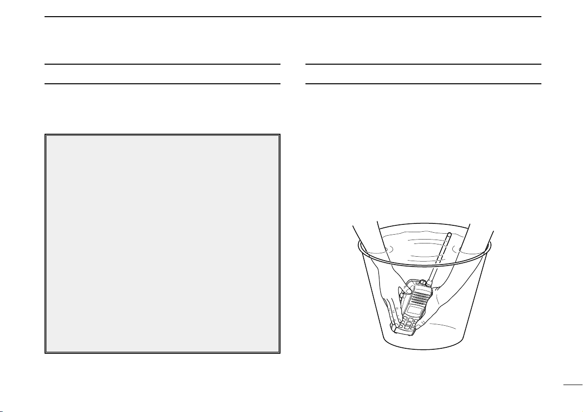
RECOMMENDATION
CLEAN THE TRANSCEIVER THOROUGHLY WITH FRESH
WATER after exposure to saltwater, and dry it before opera-
tion. Otherwise, the transceiver's keys, switches and controllers may become unusable due to salt crystallization.
NOTE: DO NOT wash the transceiver in water if there is any
reason to suspect the waterproofing may not be effective. For
example, in cases where the battery pack rubber seal is damaged, the transceiver/battery pack is cracked or broken, or
has been dropped, or when the battery pack is detached from
the transceiver.
Page 4

FOREWORD
Thank you for purchasing this Icom radio. The IC-M33
VHF MA
-
RINE TRANSCEIVER
is designed and built with Icom’s state of the
art technology and craftsmanship. With proper care this radio
should provide you with years of trouble-free operation.
IMPORTANT
READ ALL INSTRUCTIONS carefully and com-
pletely before using the transceiver.
SAVE THIS INSTRUCTION MANUAL—This in-
struction manual contains important operating instructions for
the IC-M33.
EXPLICIT DEFINITIONS
FEATURES
☞ Submersible construction
Built tough to withstand the punishing marine environment, the IC-M33’s submersible construction meets IPX7
of the corresponding International Standard IEC 60529
(2001) while using BP-251 (option) or BP-252.
☞ Floating on water
The IC-M33 floats on fresh or salt
water even when the supplied accessories are attached.
• When third-party battery pack, strap, antenna, etc. is used, it may sink.
• The battery contacts may be prone to rusting if the transceiver is kept floating in
fresh or salt water.
☞ Large, easy-to-read LCD
With dimensions of 16(H) × 32(W) mm, the IC-M33’s function display is easy to read and shows operating conditions at a glance. Backlighting and contrast can be
adjusted to suit your preferences.
☞ Simple operation
9 large buttons on the front panel provide user-friendly operation. The independent volume and channel buttons are
located on the front panel for convenient one-hand operation.
DEFINITION
RWARNING
CAUTION
NOTE
Personal injury, fire hazard or electric shock
may occur.
If disregarded, inconvenience only. No risk
of personal injury, fire or electric shock.
Equipment damage may occur.
WORD
iii
Page 5

iv
PRECAUTIONS
RWARNING! NEVER connect the transceiver to an
AC outlet. This may pose a fire hazard or result in an electric
shock.
RWARNING! NEVER hold the transceiver so that the
antenna is closer than 2.5 cm from exposed parts of the body,
especially the face or eyes, while transmitting. The transceiver will perform best if the microphone is 5 to 10 cm away
from the lips and the transceiver is vertical.
NEVER connect the transceiver to a power source other
than the BP-251 (option) or BP-252. Such a connection will
ruin the transceiver.
AVOID using or placing the transceiver in direct sunlight or
in areas with temperatures below –15°C or above +55°C.
KEEP the transceiver out of the reach of children.
KEEP the transceiver at least 0.9 meters away from your
vessel’s magnetic navigation compass.
BE CAREFUL! The transceiver’s right-side panel will
become hot when operating continuously for long periods.
BE CAREFUL! The transceiver employs waterproof
construction, which corresponds to IPX7 of the international
standard IEC 60529 (2001). However, once the transceiver
has been dropped, waterproofing cannot be guaranteed due
to the fact that the transceiver may be cracked, or the waterproof seal damaged, etc.
MAKE SURE the flexible antenna and battery pack are
securely attached to the transceiver, and that the antenna and
battery pack are dry before attachment. Exposing the inside
of the transceiver to water will result in serious damage to the
transceiver.
After exposure to water, clean the battery contacts thoroughly
with fresh water and dry them completely to remove any
water or salt residue.
Icom, Icom Inc. and the logo are registered trademarks of Icom Incorporated (Japan) in the United States, the United Kingdom, Germany, France,
Spain, Russia and/or other countries.
Page 6

v
DOC ........................................................................................... i
IN CASE OF EMERGENCY ..................................................... ii
RECOMMENDATION ............................................................... ii
FOREWORD ............................................................................ iii
IMPORTANT ............................................................................ iii
EXPLICIT DEFINITIONS .......................................................... iii
FEATURES .............................................................................. iii
PRECAUTIONS ....................................................................... iv
TABLE OF CONTENTS ............................................................ v
1 OPERATING RULES ......................................................... 1
2 SUPPLIED ACCESSORIES AND ATTACHMENTS ....... 2–3
■ Supplied accessories ....................................................... 2
■ Attachments ..................................................................... 2
3 PANEL DESCRIPTION .................................................. 4–7
■ Front, top and side panels ............................................... 4
■ Function display .............................................................. 6
4 BASIC OPERATION .................................................... 8–13
■ Channel selection ........................................................... 8
■ Receiving and transmitting ............................................ 10
■ Call channel programming ............................................ 11
■ Adjusting the volume level ............................................. 11
■ Volume mute function .................................................... 11
■ Adjusting the squelch level ........................................... 12
■ Lock function ................................................................. 12
■ Automatic backlighting .................................................. 12
■ Monitor function ............................................................ 13
■ AquaQuake water draining function .............................. 13
5 SCAN OPERATION (Except Holland version) ........ 14–15
■ Scan types .................................................................... 14
■ Setting TAG channels ................................................... 15
■ Starting a scan .............................................................. 15
6 DUALWATCH/TRI-WATCH (Except Holland version) ... 16
■ Description .................................................................... 16
■ Operation ...................................................................... 16
7 SET MODE ................................................................. 17–20
■ Set mode programming ................................................ 17
■ Set mode items ............................................................. 18
8 BATTERY CHARGING ............................................... 21–24
■ Battery caution .............................................................. 21
■ Supplied battery charger ............................................... 23
■ Optional battery case ..................................................... 23
■ Optional battery charger ............................................... 24
9 OPTIONAL SPEAKER-MICROPHONE ........................... 25
■ HM-165 descriptions ..................................................... 25
■ Attachment .................................................................... 25
10 TROUBLESHOOTING ..................................................... 26
11 VHF MARINE CHANNEL LIST ........................................ 27
12 SPECIFICATIONS............................................................. 28
13 OPTIONS .......................................................................... 29
TABLE OF CONTENTS
Page 7

1
1
OPERATING RULES
1
D Priorities
• Read all rules and regulations pertaining to priorities and
keep an up-to-date copy handy. Safety and distress calls
take priority over all others.
• You must monitor Channel 16 when you are not operating
on another channel.
• False or fraudulent distress calls are prohibited under law.
D Privacy
• Information overheard but not intended for you cannot lawfully be used in any way.
• Indecent or profane language is prohibited.
D Radio licenses
(1) SHIP STATION LICENSE
When your craft is equipped with a VHF FM transceiver, you
must have a current radio station license before using the
transceiver. It is unlawful to operate a ship station which is not
licensed.
Inquire through your dealer or the appropriate government
agency for a Ship-Radiotelephone license. This license includes the call sign which is your craft’s identification for radio
purposes.
(2) OPERATOR’S LICENSE
A restricted Radiotelephone Operator Permit is the license
most often held by small vessel radio operators when a radio
is not required for safety purposes.
The Restricted Radiotelephone Operator Permit must be
posted near the transceiver or be kept with the operator. Only
a licensed radio operator may operate a transceiver.
However, non-licensed individuals may talk over a transceiver
if a licensed operator starts, supervises, ends the call and
makes the necessary log entries.
A current copy of the applicable government rules and regulations is only required to be on hand for vessels in which a
radio telephone is compulsory. However, even if you are not
required to have these on hand it is your responsibility to be
thoroughly acquainted with all pertinent rules and regulations.
Page 8
2
SUPPLIED ACCESSORIES AND ATTACHMENTS
2
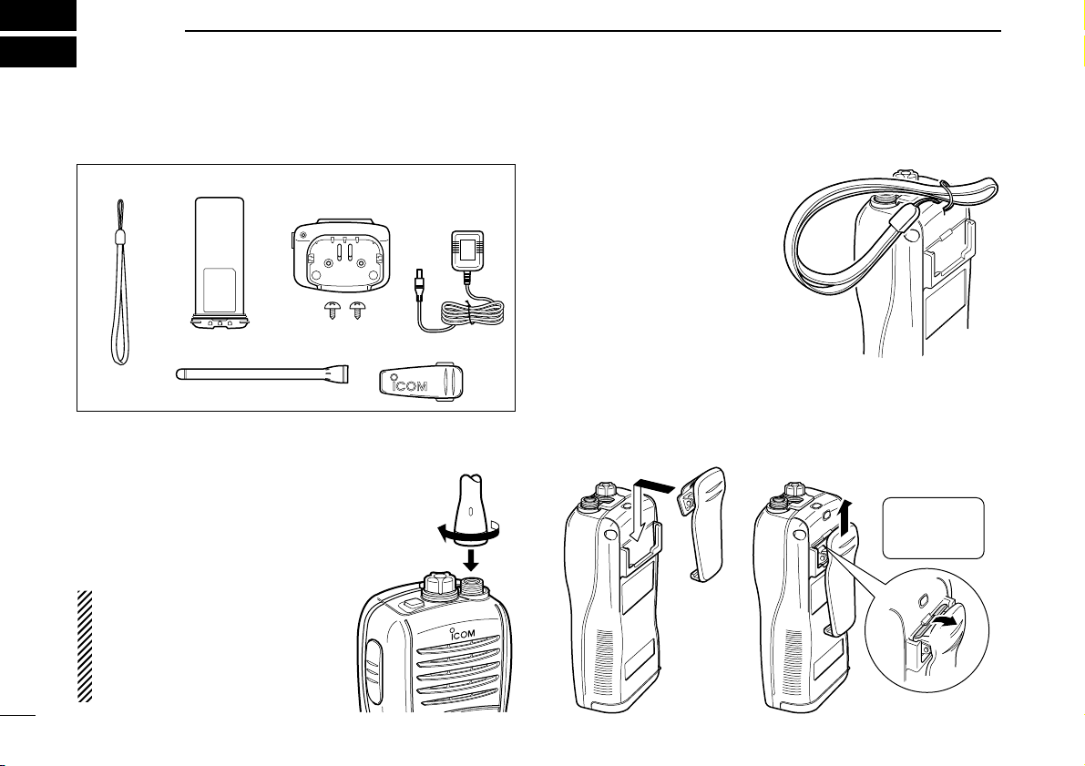
■ Supplied accessories
■ Attachments
D Flexible antenna
Connect the supplied flexible antenna to the antenna connector.
CAUTION!
• NEVER carry the transceiver
by the antenna.
• Transmitting without an antenna may damage the transceiver.
Battery packHandstrap
Belt clip
Battery charger
(with 2 screws)
Antenna
AC adapter
(Not supplied with
some version)
D Handstrap
Pass the handstrap through
the loop on the side of the
transceiver as illustrated at
right. This facilitates carrying.
D Belt clip
Attach/detach the belt clip to the transceiver as illustrated
below.
To attach the belt clip To detach the belt clip
w
Be careful!
Not to break
your nails.
q
Page 9

3
2
SUPPLIED ACCESSORIES AND ATTACHMENTS
2
ï Battery pack
To remove the battery pack:
Turn the screw counterclockwise one quarter turn, then pull
the battery pack in the direction of the arrow as shown below.
To attach the battery pack:
Insert the battery pack in the IC-M33 completely, then turn the
screw clockwise one quarter turn.
NEVER remove or insert the battery pack when the transceiver is wet or soiled. This may result water or dust getting into the transceiver/battery pack and may result in the
transceiver being damaged.
NOTE: When removing or attaching the battery pack, use
a coin or standard screwdriver to loosen or tighten the bottom screw.
CAUTION!:
When attaching or removing a battery pack, make sure the
rubber seal is set in the groove of the battery pack correctly. If the seal is not neatly in the groove it may be damaged when attaching the battery pack.
If the seal is damaged, waterproofing is not guaranteed.
Screw position
when removing battery
Screw position
when attaching battery
Make sure the rubber seal (purple) is properly seated in the
groove and dust or other material does not adhere to it.
Battery pack
Battery pack
Rubber seal
Groove
Correct position
Incorrect position
NOTE:
When attaching a battery pack, make sure dust or other
material does not adhere to the rubber seal. If dust or other
material is on the seal when attaching a battery pack, water
resistance may be compromised.
Page 10
4
PANEL DESCRIPTION
3
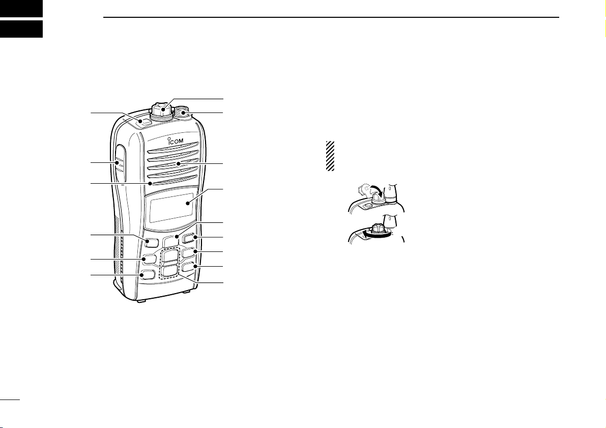
■ Front, top and side panels
q POWER SWITCH [PWR]
Push and hold to turn power ON and OFF.
w SPEAKER-MICROPHONE CONNECTOR [SP MIC] (p. 25)
Connects the optional external speaker-microphone.
NOTE: Attach the [SP MIC] cap when the optional
speaker-microphone is not used. Otherwise, water will
get into the transceiver.
e ANTENNA CONNECTOR (p. 2)
Connects the supplied antenna.
r CHANNEL KEY [CH]
➥ Selects the regular channel when pushed. (p. 9)
➥ Selects the U.S.A.,* International or ATIS
†
channel group
when pushed and held for 1 sec. (p. 9)
➥ Push to return to the previous channel before selecting
channel 16 or the call channel.
*U.K. version only; †German and Holland versions only
q Attach the
[SP MIC]
cap.
w Then rotate it clockwise
completely.
w
q
Microphone
Function display
(pgs. 6, 7)
Speaker
o
!2
!1
!0
i
t
y
u
r
w
q
e
Page 11

5
3
PANEL DESCRIPTION
3
t FAVORITE/TAG KEY [FAV•TAG]
➥ While pushing and holding this key, push [Y]/[Z] to se-
lect the favorite (TAG) channels with ignoring untagged
channels in the selected channel group in sequence.
(p. 8)
• Pushing this key only advances the displayed TAG channel.
➥ Push and hold for 1 sec. to set or clear the displayed
channel as a TAG (scanned) channel. (p. 15)
➥ While pushing and holding this key, turn power ON to
clear or set all TAG channels (when no TAG channel has
been set) in the selected channel group. (p. 15)
y SQUELCH/MONITOR KEY [SQL•MONI]
➥ Push this key, then adjust the squelch level with [Y]/[Z].
(p. 12)
➥ Manually opens the squelch for monitoring the channel
while pushing and holding. (p. 13)
➥ While pushing and holding this key, turn power ON to
enter the set mode. (p. 17)
u TRANSMIT POWER/LOCK KEY [H/L•LOCK]
➥ Selects high or low power when pushed. (p. 10)
➥ Toggles between the key lock function ON/OFF when
pushed and held for 1 sec. (p. 12)
i CHANNEL UP/DOWN KEYS [YY]/[ZZ]
➥ Selects an operating channel. (pgs. 8, 9)
➥ Selects the set mode setting of the item. (p. 17)
➥ Checks TAG channels or changes scanning direction
during scan. (p. 15)
o SCAN/DUAL KEY [SCAN•DUAL]
➥ Push to start or stop normal or priority scan. (p. 15)
➥ Push and hold for 1 sec. to enter watch mode. (p. 16)
➥ Push and hold this key and [H/L], to activate the
AquaQuake function. (p. 13)
➥ Exits watch mode when pushed during watch operation.
(p. 16)
!0 VOLUME KEY [VOL•MUTE]
➥ Push this key, then adjust the volume level with [Y]/[Z].
(p. 11)
➥ Push and hold for 1 sec. to activate the volume mute
function. (p. 11)
!1 CHANNEL 16 KEY [16•C]
➥ Push to select Channel 16. (p. 8)
➥ Push and hold for 1 sec. to select the call channel. (p. 8)
➥ Enters call channel programming condition when the call
channel is selected and this key is pushed and held for 3
sec. (p. 11)
➥ Push to exit set mode during set mode operation. (p. 17)
!2 PTT SWITCH [PTT]
Push and hold to transmit; release to receive. (p. 10)
Page 12

6
3 PANEL DESCRIPTION
■ Function display
q TRANSMIT INDICATOR (p. 10)
Appears while transmitting.
w BUSY INDICATOR
➥ Appears when receiving a signal or when the squelch
opens. (p. 10)
➥ Blinks while monitoring. (p. 13)
e TAG CHANNEL INDICATOR (p. 15)
Appears when a TAG channel is selected.
r CALL CHANNEL INDICATOR (p. 8)
Appears when the call channel is selected.
t LOCK INDICATOR (p. 12)
Appears while the lock function is activated.
y BATTERY INDICATOR
Indicates remaining battery power.
u SCAN INDICATOR (p. 15)
Blinks while scanning.
i DUALWATCH/TRI-WATCH INDICATORS (p. 16)
“DUAL” appears during dualwatch; “TRI” appears during
tri-watch.
o DUPLEX INDICATOR
Appears when a duplex channel is selected.
!0 SUB CHANNEL READOUT
➥ Indicates Channel 16 during priority scan, dualwatch or
tri-watch. (p. 16)
➥ Indicates the set mode item while in set mode. (p. 17)
➥ Indicates the squelch level while squelch setting. (p. 12)
➥ Indicates the volume level while volume setting. (p. 11)
Indication
Full Middle
Charging
required
No battery
Battery level
blinks when the battery is exhausted.
blinks when the battery is over charged.
!5 !3!4
i
u
o
!2
!1
!0
!8
!6
qer ytw
!7
Page 13

7
3
PANEL DESCRIPTION
3
!1 SQUELCH LEVEL INDICATOR
Shows the squelch level.
!2 VOLUME LEVEL INDICATOR
➥ Shows the volume level.
➥ Blinks when the volume mute is activated. (p. 11)
!3 VOLUME LEVEL ADJUSTING INDICATOR (p. 11)
Blinks while adjusting the volume level.
!4 SQUELCH LEVEL ADJUSTING INDICATOR (p. 12)
Blinks while adjusting the squelch level.
!5 CHANNEL NUMBER READOUT
➥ Indicates the selected operating channel number.
➥ In set mode, indicates the selected condition.
!6 CHANNEL GROUP INDICATOR (p. 9)
“UU” appears when U.S.A.*; “” appears when International.
*U.K. version only
!7 ATIS INDICATORS (p. 9)
➥ “ATIS” appears when the channel group, which ATIS
function is activated, is selected.
(Available with German
and Holland versions only)
!8 LOW POWER INDICATOR (p. 10)
➥ “LOW” appears when low power is selected.
➥ “LOW” blinks when switching forced low power mode
because of a high temperature error or low voltage.
Page 14

8
BASIC OPERATION
4
■ Channel selection
IMPORTANT!: Prior to using the transceiver for the first
time, the battery pack must be fully charged for optimum
life and operation. To avoid damage to the transceiver, turn
the power OFF while charging.
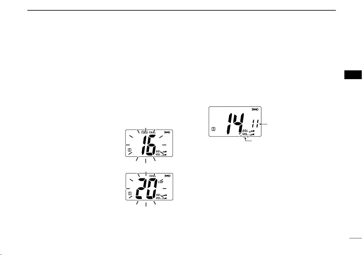
D Channel 16
Channel 16 is the distress and safety channel. It used for establishing initial contact with a station and for emergency
communications. Channel 16 is monitored during both Dualwatch and Tri-watch. While standing by, you must monitor
Channel 16.
q Push [16] momentarily to select Channel 16.
w Push [CH] to return to the channel used before Channel
16, or push [YY]/[ZZ] to select a channel.
Convenient!
While pushing and holding [FAV], push [Y]/[Z] to select the
favorite (TAG) channels with ignoring untagged channels in
the selected channel group in sequence.
• Pushing [FAV] only advances the displayed TAG channel.
• The favorite channels are selected using the TAG channel setting.
(p. 15)
D Call channel
Each regular channel group has separate leisure-use call
channels. The call channel is monitored during Tri-watch. The
call channels can be programmed (p. 11) and are used to
store your most often used channel in each channel group for
quick recall.
q Push and hold [C] (16) for 1 sec. to select the call channel
of the selected channel group.
•“CALL” and call channel number appear.
• Each channel group may have an independent call channel after
programming a call channel. (p. 11)
w Push [CH] to return to the channel used before call chan-
nel, or push [YY]/[ZZ] to select a channel.
Push and hold
for 1 sec.
Push
Page 15

9
4
BASIC OPERATION
4
D U.S.A., International and ATIS channels
The IC-M33 is pre-programmed with U.S.A.*, International
and ATIS
†
channels. These channel groups may be specified
for the operating area.
*U.K. version only; †German and Holland versions only
q Push [CH] to select a regular channel.
w Push and hold [CH] for 1 sec. to change the channel
group. Repeat to advance to the next group.
• U.S.A., International and ATIS channel groups can be selected in
sequence.
e Push [YY]/[ZZ] to select a channel.
•“DUP” appears for duplex channels.
Push and hold
for 1 sec.
U.S.A. channels
International channels
ATIS channels
Page 16

10
4 BASIC OPERATION
■ Receiving and transmitting
CAUTION: Transmitting without an antenna will damage
the transceiver.
q Push and hold [PWR] to turn power ON.
w Set the audio and squelch levels.
➥ Push [SQL], and push [ZZ] several times to open the squelch.
➥ Push [VOL], then push [YY]/[ZZ] to adjust the volume level.
➥ Push [SQL], and push [YY] until the noise disappears.
e Push [YY]/[ZZ] to select the desired channel.
• When receiving a signal, “” appears and audio is emitted
from the speaker.
• Further adjustment of the audio may be necessary at this point.
r Push [H/L] to select the output power if necessary.
• “LOW” appears when low power is selected; no indication when
high power is selected.
• Choose low power to conserve battery power, choose high
power for longer distance communications.
• Some channels are for low power only.
t Push and hold [PTT] to transmit, then speak into the
microphone.
• “” appears.
• Channel 70 cannot be used for transmission.
y Release [PTT] to receive.
IMPORTANT: To maximize the readability of your trans-
mitted signal, pause a few sec. after pushing [PTT], hold
the microphone 5 to 10 cm from your mouth and speak
into the microphone at a normal voice level.
NOTE: The transceiver has a power save function to conserve the battery power. The power save function activates
automatically when no signal is received for 5 sec.
Microphone
r Set output
power
q Power ON
w Set the
squelch level
w Set volume
t Push to
transmit
y Release to
receive
e Set channel
Set the squelch
and volume level.
w
Page 17
11
4
BASIC OPERATION
4
■ Call channel programming
Call channel is used to access Channel 16 (default; may differ
according to version), however, you can program the call chan-
nel with your most often-used channels in each channel
group for quick recall.
q Push and hold [CH] for 1 sec. several times to select the
desired channel group
(U.S.A., International or ATIS)
to be
programmed. (p. 9)
w Push and hold [C] (16) for 1 sec. to select the call channel
of the selected channel group.
•“CALL” and call channel number appear.
e Push and hold [C] (16) again for 3
sec. (until a long beep changes to
2 short beeps) to begin call channel programming.
• Channel number starts blinking.
r Push [YY]/[ZZ] to select the desired
channel.
t Push [16] to program the dis-
played channel as the call channel.
• The channel number stops blinking.
■ Adjusting the volume level
The volume level can be adjusted with [VOL] and [YY]/[ZZ].
q Push [VOL], then adjust the volume level with [YY]/[ZZ].
•“VOL” indicator starts blinking.
• There are 31 volume levels and OFF.
• When no key is pushed for 5 sec., the transceiver returns to nor-
mal condition.
w Push [VOL] again to return to normal condition.
■ Volume mute function
The volume mute function can be activated temporarily with
[MUTE] (VOL).
q Push and hold [MUTE] (VOL) for 1 sec to activate the vol-
ume mute function.
• The audio is muted.
• The volume level indicator starts blinking.
w Push [VOL] again or turn power OFF to turn the volume
mute function OFF.
Indicates the
volume level.
Blinks during volume level adjustment.
Page 18

12
4 BASIC OPERATION
■ Adjusting the squelch level
To adjust the IC-M33’s squelch level, use the [YY]/[ZZ] keys as
described below. In order to receive signals properly, as well
as for the scan to function effectively, the squelch must be adjusted to the proper level.
q Push [SQL], then adjust the squelch level with [YY]/[ZZ].
• “SQL” indicator starts blinking.
• There are 11 squelch levels to choose from: OP is completely
open; 10 is tight squelch; 1 is loose squelch.
• If no key is pushed for 5 sec., the transceiver returns to normal
operation.
w Push [SQL] again to return to normal condition.
■ Lock function
This function electronically locks all keys (except for [PTT],
[SQL•MONI], [VOL•MUTE], [H/L•LOCK] and [YY]/[ZZ]*) to
prevent accidental channel changes and function access.
* After pushing [VOL•MUTE] or [SQL•MONI] only.
➥ Push and hold [LOCK] (H/L) for 1 sec. to turn the lock
function ON and OFF.
■ Automatic backlighting
This function is convenient for nighttime operation. The automatic backlighting can be activated in set mode. (p. 19)
➥ Push any key except for [PTT] to turn the backlighting ON.
• The backlighting is automatically turned OFF after 5 sec. of inactivity.
Push and hold
for 1 sec.
Appears while the lock
function is used.
Blinks during squelch
level adjustment.
Indicates the
squelch level.
Page 19
13
4
BASIC OPERATION
4
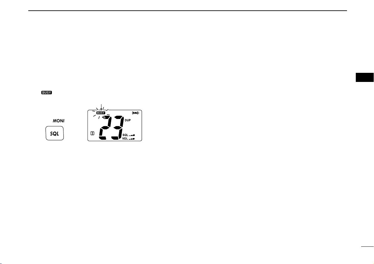
■ Monitor function
The monitor function opens the squelch. See p. 5 for details
of the monitor key action.
➥ The monitor function activates while pushing and holding
[MONI] (SQL).
•“ ” blinks and audio is emitted.
■
AquaQuake water draining function
The IC-M33 uses a new technology to clear water away from
the speaker grill: AquaQuake. AquaQuake helps drain water
away from the speaker housing (water that might otherwise
muffle the sound coming from the speaker). The IC-M33
emits a vibrating beep when this function is being used.
➥ Push and hold both [SCAN] and [H/L].
• A low beep tone sounds for 9 sec. to drain water, regardless of
volume level setting.
• The transceiver does not perform key operations while the
AquaQuake function is activated. The AquaQuake function can not
be activated when an optional speaker-microphone is connected.
Push and hold
Blinks while the monitor function is used.
Page 20
14
SCAN OPERATION (Except Holland version)
5
■ Scan types
Scanning is an efficient way to locate signals quickly over a
wide frequency range. The transceiver has priority scan and
normal scan.
In addition, auto scan function is available for standby convenience. This function can be activated depending on the setting in set mode. (p. 18)
Set the TAG channels (scanned channels) before scanning.
Clear any TAG channels which inconveniently stop scanning,
such as digital communications.
Choose priority or normal scan in set mode. (p. 18)
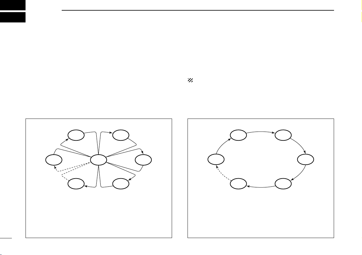
PRIORITY SCAN
Priority scan searches through all TAG channels in sequence while monitoring Channel 16. When a signal is detected on Channel 16, scan pauses until the signal disappears; when a signal is detected on a channel other than
Channel 16, scan becomes dualwatch until the signal disappears.
CH 88
CH 01
CH 16
CH 02
CH 05 CH 04
CH 03
NORMAL SCAN
Normal scan, like priority scan, searches through all TAG
channels in sequence. However, unlike priority scan, Channel 16 is not checked unless Channel 16 is set as a TAG
channel.
CH 01 CH 02
CH 88
CH 05 CH 04
CH 03
Page 21

15
5
SCAN OPERATION
■ Setting TAG channels
For more efficient scanning, set the desired channels as TAG
channels or clear the TAG setting from unwanted channels.
Channels that are not tagged will be skipped during scanning.
TAG channels can be assigned to each channel group
(U.S.A., International and ATIS) independently.
q Push and hold [CH] for 1 sec. several times to select the
desired channel group, if desired.
w Select the desired channel to be set as a TAG channel.
e Push and hold [TAG] (FAV) for 1 sec. to set the displayed
channel as a TAG channel.
•“ ” appears in the function display.
r To cancel the TAG channel setting, push and hold [TAG]
(FAV) for 1 sec.
•“ ” disappears.
✔ Clearing (or setting) all tagged channels
While pushing and holding [TAG] (FAV), turn power ON to
clear all TAG channels in the selected channel group.
• Repeat above procedure to set all channels as TAG channels
(when no TAG channel has been set.)
■ Starting a scan
Set the priority scan function, scan resume timer and auto
scan function in advance, using set mode. (p. 18)
q Push and hold [CH] for 1 sec. several times to select the
desired channel group, if desired.
w Push [SCAN] to start priority or normal scan.
•“SCAN” blinks in the function display.
•“16” appears on the sub channel readout during priority scan.
• When a signal is received, scan pauses until the signal disap-
pears or resumes after pausing 5 sec. according to the scan resume timer setting. (Channel 16 is still monitored during priority
scan.)
• Push [Y]/[Z] to check which channels have been set as TAG
channels, change the scanning direction or resume the scan
manually.
e To stop the scan, push [SCAN].
•“SCAN” disappears.
• Pushing [PTT], [16], [CH] or [FAV] also stops the scan.
5
Scan starts
to stop the scan
Push
Push
[Example]: Starting a normal scan.
When a signal is received
Page 22

16
DUALWATCH/TRI-WATCH (Except Holland version)
6
■ Description
Dualwatch monitors Channel 16 while you are receiving
on another channel; Tri-watch monitors Channel 16 and the
call channel while receiving another channel. Dualwatch/Triwatch is convenient for monitoring Channel 16 when you are
operating on another channel.
■ Operation
q Select Dualwatch or Tri-watch in set mode. (p. 19)
w Select the desired channel.
e Push and hold [DUAL] (SCAN) for 1 sec. to start Dual-
watch or Tri-watch (depending on set mode setting).
•“DUAL” blinks during dualwatch; “TRI” blinks during tri-watch.
• A beep tone sounds when a signal is received on Channel 16.
• Tri-watch becomes dualwatch when receiving a signal on the call
channel.
r To cancel dualwatch/tri-watch, push [SCAN] again.
DUALWATCH/TRI-WATCH SIMULATION
• If a signal is received on Channel 16, dualwatch/tri-watch
pauses on Channel 16 until the signal disappears.
• If a signal is received on the call channel during Tri-watch,
Tri-watch becomes Dualwatch until the signal disappears.
• To transmit on the selected channel during Dualwatch/Triwatch, push and hold [PTT].
Dualwatch Tri-watch
Call channel
[Example]: Operating Tri-watch on INT channel 07.
Tri-watch starts.
Signal is received on call
channel.
Signal received on Channel
16 takes priority.
Tri-watch resumes after
the signal disappears.
Page 23

17
7
SET MODE
6
7
■ Set mode programming
Set mode is used to change the settings for 11 transceiver
functions: beep tone function, priority scan function, scan resume timer, auto scan function, dual/tri-watch function, monitor key action, automatic backlighting, LCD contrast setting,
power save function, squelch sensitivity and low fix function*.
*Appears only when the optional battery case is attached; Not avail-
able with German version.
D Set mode operation
q Turn power OFF.
w While pushing [SQL], turn power ON to enter set mode.
• “bP” appears.
e Push [SQL] or [YY]/[ZZ] while pushing and holding [SQL]
to select the desired item, if necessary.
r Push [YY]/[ZZ] to select the desired setting of the item.
t To exit set mode, push [16].
D SET MODE ITEMS (The display shows the current settings, and the selected function is displayed in the dotted circle.)
• Auto scan
†
Starting item
• Beep tone• Low fix* • Scan resume timer
†
• Dual/Tri-watch
†
• Automatic
backlighting
• Power save • LCD contrast • Monitor key action
• Squelch sensitivity
• Priority scan
†
: Push
+ [Z]
: Push or
+ [Y]
*Appears only when the optional
battery case is attached; Not
available with German version.
†
Not available with Holland version.
Page 24

18
7 SET MODE
■ Set mode items
D Beep tone function “bP”
Select the key touch beep sound from ON or US, or turn sound
OFF.
• US : The preset beeps (e.g. do, re, mi) sound
• ON : A fixed beep sounds (default)
• OFF: Silent operation
D Priority scan function “Pr”
(Not available with Holland version)
The transceiver has 2 scan types— normal (OFF) and priority
(ON) scans. Normal scan searches all TAG channels in the
selected channel group. Priority scan searches all TAG channels in sequence while monitoring Channel 16.
D Scan resume timer “St”
(Not available with Holland version)
The scan resume timer can be set as a pause (OFF) or timer
scan (ON). When OFF is selected, the scan pauses until a
received signal disappears. When ON is selected, the scan
pauses for 5 sec. after receiving a signal and then resumes
even if the signal is being received.
D Auto scan function “AS”
(Not available with Holland version)
The auto scan function starts the desired scan automatically
when no signal is received, and no operation is performed for
30 sec.
Push
Auto scan OFF (default) Auto scan ON
Push
Scan resume timer OFF
(default)
Scan resume timer ON
Push
Normal scan Priority scan (default)
Push
Beep tone ON (default) Beep tone OFF
Page 25
19
7
SET MODE
7
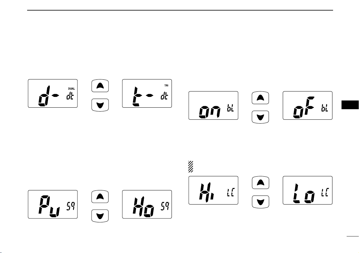
D Dual/Tri-watch function “dt”
(Not available with Holland version)
This item selects dual or tri-watch as desired. See p. 16 for
details.
D Monitor key action “Sq”
The monitor key opens the squelch temporarily. This key action contains PUSH (Pu) or HOLD (Ho) settings as shown
below.
• Pu (PUSH): After pushing [MONI] (SQL) for 1 sec., the squelch opens
and emits audio. The squelch is held open while continuously pushing and holding [MONI] (SQL). (default)
• Ho (HOLD): After pushing [MONI] (SQL) for 1 sec., the squelch
opens and emits audio even while [MONI] (SQL) is released. To close the squelch, push any key.
D Automatic Backlighting “bL”
This function is convenient for nighttime operation. The backlight can be selected from ON and OFF.
• The backlight is automatically activated when any key except for
[PTT] is pushed.
• The backlight is automatically turned OFF after 5 sec. of inactivity.
D LCD contrast setting “LC”
Set the LCD contrast level from High contrast or Low contrast.
NOTE: The LCD contrast level between High contrast and
Low contrast makes no difference indoors.
Push
High contrast (default) Low contrast
Push
Auto backlighting ON
(default)
Auto backlighting OFF
Push
Push setting (default) Hold setting
Push
Dualwatch function
(default)
Tri-watch function
Page 26

20
7 SET MODE
D Power save function “PS”
The power save function reduces current drain by deactivating the receiver circuit for preset intervals.
• ON : The power save function is turned ON. The power save function will activate when no signal is received, and no operation is performed for 5 sec.
• OFF : The power save function is turned OFF.
D Squelch sensitivity “SS”
When this function is turned ON, rejection of noise is improved so that the squelch is not easily affected by noise.
D Low fix function “LF”
(Appears only when the optional battery case is attached. Not avail-
able with German version.)
When this function is turned ON, the output power is fixed to
low except for channel 16.
Push
Low fix function
OFF (default)
Low fix function ON
Push
Squelch sensitivity
OFF (default)
Squelch sensitivity
ON
Push
Power save ON
(default)
Power save OFF
Page 27

21
8
BATTERY CHARGING
1
2
3
4
5
6
7
8
9
10
11
12
13
14
15
16
■ Battery caution
R DANGER! Use and charge only specified Icom battery
pack with Icom radios or Icom charger. Only Icom battery
pack is tested and approved for use and charge with Icom radios or Icom charger. Using third-party or counterfeit battery
packs or charger may cause smoke, fire, or cause the battery
to burst.
DD
Battery caution
R DANGER! DO NOT hammer or otherwise impact the bat-
tery. Do not use the battery if it has been severely impacted or
dropped, or if the battery has been subjected to heavy pressure. Battery damage may not be visible on the outside of the
case. Even if the surface of the battery does not show cracks
or any other damage, the cells inside the battery may rupture
or catch fire.
R DANGER! NEVER use or leave battery pack in areas with
temperatures above +60˚C. High temperature buildup in the
battery, such as could occur near fires or stoves, inside a sunheated car, or by setting the battery in direct sunlight may
cause the battery to rupture or catch fire. Excessive temperatures may also degrade battery performance or shorten battery life.
R DANGER! DO NOT expose the battery to rain, snow, sea-
water, or any other liquids. Do not charge or use a wet battery. If the battery gets wet, be sure to wipe it dry before
using. The battery by itself is not waterproof.
R DANGER! NEVER incinerate a used battery pack since
internal battery gas may cause them to rupture or may cause
an explosion.
R DANGER! NEVER solder the battery terminals, or NEVER
modify the battery pack. This may cause heat generation, and
the battery may rupture, emit smoke or catch fire.
R DANGER! Use the battery only with the transceiver for
which it is specified. Never use a battery with any other equipment, or for any purpose that is not specified in this instruction
manual.
R DANGER! If fluid from inside the battery gets in your eyes,
blindness can result. Rinse your eyes with clean water, without rubbing them, and see a doctor immediately.
Misuse of Lithium-Ion batteries may result in the following hazards: smoke, fire, or the battery may rupture.
Misuse can also cause damage to the battery or degradation of battery performance.
Page 28

22
8 BATTERY CHARGING
WARNING! Immediately stop using the battery if it emits an
abnormal odor, heats up, or is discolored or deformed. If any
of these conditions occur, contact your Icom dealer or distributor.
WARNING! Immediately wash, using clean water, any part of
the body that comes into contact with fluid from inside the battery.
WARNING! NEVER put the battery in a microwave oven,
high-pressure container, or in an induction heating cooker.
This could cause overheating, a fire, or cause the battery to
rupture.
CAUTION! Always use the battery within the specified temperature range for the transceiver (–15˚C to +55˚C) and the
battery itself (–20˚C to +60˚C). Using the battery out of its
specified temperature range will reduce the battery’s performance and battery life.
CAUTION! Shorter battery life could occur if the battery is left
fully charged, completely discharged, or in an excessive temperature environment (above +50˚C) for an extended period
of time. If the battery must be left unused for a long time, it
must be detached from the radio after discharging. You may
use the battery until the battery indicator shows half-capacity
( ), then keep it safely in a cool dry place with the temperature between –20˚C to +20˚C.
DD
Charging caution
R DANGER! NEVER charge the battery pack in areas with
extremely high temperatures, such as near fires or stoves, inside a sun-heated car, or in direct sunlight. In such environments, the safety/protection circuit in the battery will activate,
causing the battery to stop charging.
WARNING! DO NOT charge or leave the battery in the battery charger beyond the specified time for charging. If the battery is not completely charged by the specified time, stop
charging and remove the battery from the battery charger.
Continuing to charge the battery beyond the specified time
limit may cause a fire, overheating, or the battery may rupture.
WARNING! NEVER insert the battery and transceiver (battery attached to the transceiver) into the charger if it is wet or
soiled. This could corrode the battery charger terminals or
damage the charger. The charger is not waterproof.
CAUTION! DO NOT charge the battery outside of the specified temperature range: ±0˚C to +40˚C. Icom recommends
charging the battery at +20˚C. The battery may heat up or
rupture if charged out of the specified temperature range. Additionally, battery performance or battery life may be reduced.
Page 29
23
8
BATTERY CHARGING
1
2
3
4
5
6
7
8
9
10
11
12
13
14
15
16
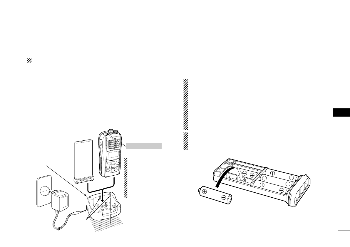
■ Supplied battery charger
ï Charging connections
Do not charge batteries other than the BP-252.
q Attach the BC-173 to a flat surface, such as a desk, if desired.
w Connect the AC adapter as shown below.
e Insert the battery pack with/without the transceiver into the
charger.
• The charge indicator lights orange.
• The charge indicator blinks orange (or orange/green alternately)
when the protector is activated.
r Charge the battery pack approx. 10 hours, depending on
the remaining battery charge.
• The charge indicator lights green when charging is completed.
■ Optional battery case
When you would like to use the optional AAA(LR03) size battery case (BP-251), install the batteries as illustrated below.
Be sure to observe the correct polarity.
CAUTION:
• When installing batteries, make sure they are all the
same brand, type and capacity. Also, do not mix new and
old batteries together.
• Keep battery contacts clean. It’s a good idea to clean battery terminals once a week.
• When using the optional battery case, output power level
is 2 W (at high; except German version).
NOTE: The transceiver may sink when the optional battery
case is attached. (Depends on the weight of the installed
batteries.)
Charge indicator
lights orange when
the battery pack
(with/without the
transceiver) is inserted.
BC-173
Supplied
screws
Battery pack
Transceiver
AC adapter
Turn power OFF
NOTE: The battery
charger, BC-173,
has a charging
timer. The timer
stops the charging
process after 14
hours (approx.).
Page 30

24
8 BATTERY CHARGING
■ Optional battery charger
D BC-162 installation D Charging
q Connect the AC adapter as shown below.
w Insert the battery pack with/without the transceiver into the
charger.
• The charge indicator lights orange.
• The charge indicator blinks orange (or red) when the protector
is activated.
e Charge the battery pack approx. 2 hours, depending on
the remaining battery charge.
• The charge indicator lights green when charging is completed.
NOTE: The battery charger, BC-162, has a charging
timer. The timer stops the charging process after 4
hours (approx.).
BC-162
AC adapter
(Optional for
some versions)
Charge
indicator
Turn power OFF
Battery pack
Transceiver
Supplied screwsSupplied screws
• To a desktop • To a wall
• For added stability
Eyelet:
Use a rubber band to
secure the transceiver,
if desired.
Page 31
25
9
OPTIONAL SPEAKER-MICROPHONE
1
2
3
4
5
6
7
8
9
10
11
12
13
14
15
16
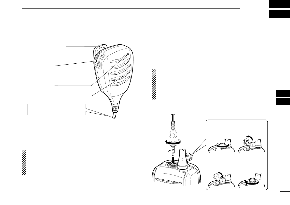
■ HM-165 descriptions
NEVER immerse the connector in water. If the connector be-
comes wet, be sure to dry it BEFORE attaching it to the transceiver.
NOTE: The microphone is located at the top of the
speaker-microphone, as shown in the diagram above. To
maximize the readability of your transmitted signal (voice),
hold the microphone approx. 2.5 cm from your mouth, and
speak in a normal voice level.
■ Attachment
Turn power OFF before attaching the speaker-microphone.
Then, insert the speaker-mic connector onto the [SP MIC]
connector and carefully screw it tight, as shown in the diagram below. Be careful not to cross-thread the connection.
IMPORTANT: KEEP the transceiver’s [SP MIC] connector
cap attached when the speaker-microphone is not in use.
If the cover is not attached, water will get into the transceiver. Moreover, the terminals (pins) will become rusty, or
the transceiver will function abnormally if the connector has
become wet.
CAUTION: Attach the speaker-microphone’s
connector securely to prevent accidental
loss, or water intrusion in the connector.
Detaching:
Rotate the [SP MIC] cap counterclockwise (q), then detach it (w).
Attaching:
Attach the
[SP MIC]
cap (q), then
rotate it clockwise completely (
w
).
q
w
q
w
PTT switch
Transmits during push.
Receives during release.
Microphone
Speaker
Alligator type clip
To attach the speaker-mic.
to your shirt or collar, etc.
Turn the transceiver power OFF
when connecting the HM-165.
Page 32

26
TROUBLESHOOTING
10
PROBLEM POSSIBLE CAUSE SOLUTION REF.
No sound from speaker. • Squelch level is too high.
• Volume level is too low.
• Speaker has been exposed to water.
p. 12
p. 11
p. 13
• Set squelch to the threshold point.
• Push [YY]/[ZZ] after pushing [VOL] to set a
suitable level.
• Drain water from the speaker.
The transceiver does
not turn ON.
• The battery is exhausted.
• The battery pack is not attached correctly.
p. 23
p. 3
• Recharge the battery pack.
• Attach the battery pack correctly.
Transmitting is impossible, or high power can
not be selected.
• Some channels are for low power or receive only.
• The battery is exhausted.
• The battery over charged.
• The output power is set to low.
pgs. 8,
9, 27
p. 23
—
p. 10
• Change channels.
• Recharge the battery pack.
• Verify the battery voltage is correct.
• Push [H/L] to select high power.
The displayed channel
cannot be changed.
• Lock function is activated. • Push and hold [LOCK] (H/L) for 1 sec. to
cancel the function.
p. 12
Scan does not start. •“TAG” channels are not programmed. • Set the desired channels as “TAG” channels. p. 15
No beeps. • Beep tone function is turned OFF. • Set the beep tone to ON (Fix Beep/User
Beep) in set mode.
p. 18
Battery voltage error • The connected battery pack’s voltage is
more than 11 V.
• Verify the battery voltage is correct. —
Page 33

27
11
VHF MARINE CHANNEL LIST
1
2
3
4
5
6
7
8
9
10
11
12
13
14
15
16
• International channels
01
02
03
04
05
06
07
08
09
10
156.050
156.100
156.150
156.200
156.250
156.300
156.350
156.400
156.450
156.500
160.650
160.700
160.750
160.800
160.850
156.300
160.950
156.400
156.450
156.500
11
12
13
14
15*
1
16
17*
1
18
19
20
156.550
156.600
156.650
156.700
156.750
156.800
156.850
156.900
156.950
157.000
156.550
156.600
156.650
156.700
156.750
156.800
156.850
161.500
161.550
161.600
21
22
23
24
25
26
27
28
60
61
157.050
157.100
157.150
157.200
157.250
157.300
157.350
157.400
156.025
156.075
161.650
161.700
161.750
161.800
161.850
161.900
161.950
162.000
160.625
160.675
62
63
64
65
66
67
68
69
70
71
156.125
156.175
156.225
156.275
156.325
156.375
156.425
156.475
Rx only
156.575
160.725
160.775
160.825
160.875
160.925
156.375
156.425
156.475
156.525
156.575
72
73
74
75*
2
76*
2
77
78
79
80
81
156.625
156.675
156.725
156.775
156.825
156.875
156.925
156.975
157.025
157.075
156.625
156.675
156.725
156.775
156.825
156.875
161.525
161.575
161.625
161.675
82
83
84
85
86
87
88
157.125
157.175
157.225
157.275
157.325
157.375
157.425
161.725
161.775
161.825
161.875
161.925
157.375
157.425
CH
Frequency (MHz)
Transmit Receive
CH
Frequency (MHz)
Transmit Receive
CH
Frequency (MHz)
Transmit Receive
CH
Frequency (MHz)
Transmit Receive
CH
Frequency (MHz)
Transmit Receive
CH
Frequency (MHz)
Transmit Receive
• USA channels (for U.K. versions only)
*UK marina channels: M1=37A (Tx/Rx: 157.850 MHz), M2=P4 (Tx/Rx: 161.425 MHz) for U.K. versions only.
01A
––
03A
––
05A
06
07A
08
09
10
11
156.050
–––
156.150
–––
156.250
156.300
156.350
156.400
156.450
156.500
156.550
156.050
–––
156.150
–––
156.250
156.300
156.350
156.400
156.450
156.500
156.550
12
13
14
15
16
17
18A
19A
20
20A
21A
156.600
156.650
156.700
156.750
156.800
156.850
156.900
156.950
157.000
157.000
157.050
156.600
156.650
156.700
156.750
156.800
156.850
156.900
156.950
161.600
157.000
157.050
22A
23A
24
25
26
27
28
37A*
61A
––
63A
157.100
157.150
157.200
157.250
157.300
157.350
157.400
157.850
156.075
–––
156.175
157.100
157.150
161.800
161.850
161.900
161.950
162.000
157.850
156.075
–––
156.175
64A
65A
66A
67
68
69
70
71
72
73
74
156.225
156.275
156.325
156.375
156.425
156.475
Rx only
156.575
156.625
156.675
156.725
156.225
156.275
156.325
156.375
156.425
156.475
156.525
156.575
156.625
156.675
156.725
77
78A
79A
80A
81A
82A
83A
84
84A
85
85A
156.875
156.925
156.975
157.025
157.075
157.125
157.175
157.225
157.225
157.275
157.275
156.875
156.925
156.975
157.025
157.075
157.125
157.175
161.825
157.225
161.875
157.275
86
86A
87
87A
88
88A
P4*
157.325
157.325
157.375
157.375
157.425
157.425
161.425
161.925
157.325
161.975
157.375
162.025
157.425
161.425
CH
Frequency (MHz)
Transmit Receive
CH
Frequency (MHz)
Transmit Receive
CH
Frequency (MHz)
Transmit Receive
CH
Frequency (MHz)
Transmit Receive
CH
Frequency (MHz)
Transmit Receive
CH
Frequency (MHz)
Transmit Receive
*1 Channels 15 and 17 may also be used for on-board communications provided the effective radiated power does not exceed 1 W, and subject to the national regu-
lations of the administration concerned when these channels are used in its territorial waters.
*
2
The use of these channels should be restricted to navigation-related communications only and all precautions should be taken to avoid harmful interference to
channel 16, e.g. by limiting the output power to 1 W or by means geographical separation.
Page 34

28
SPECIFICATIONS
12
ï GENERAL
• Frequency coverage : Transmit 156.000–161.450 MHz
Receive 156.000–163.425 MHz
• Mode : FM (16K0G3E)
• Channel spacing : 25 kHz
• Power supply requirement : BP-251 and BP-252 only
• Current drain (at 7.4 V DC) : TX High (5 W) 1.5 A
TX Low (1 W) 0.7 A
Max. audio 0.2 A
Power save 20 mA typical
• Frequency stability : ±1.5 kHz
• Useable temperature range : –15°C to +55°C
• Dimensions : 62 (W) × 141.5(H) × 43(D) mm
(Projections not included)
• Weight : Approx. 305 g
(incl. BP-252, FA-SC58V and MB-109)
ï TRANSMITTER
• Output power (at 7.4 V DC) : 5 W (High)* and 1 W (Low)*
*1 W (High) and 0.5 W (Low) only for
German version.
• Modulation system : Variable reactance frequency
modulation
• Max. frequency deviation : ±5 kHz
• Adjacent channel power : 70 dB
• Spurious emissions : 0.25 µW
ï RECEIVER
• Receive system : Double-conversion
superheterodyne
• Sensitivity (20 dB SINAD) : –2 dBµ emf typical
• Squelch sensitivity : –6 dBµ emf typical (at threshold)
• Intermodulation rejection ratio : 68 dB
• Spurious response rejection ratio : 70 dB
• Adjacent channel selectivity : 70 dB
• Audio output power : 0.2 W at 10% distortion with an
8 Ω load
All stated specifications are subject to change without notice or
obligation.
Page 35

29
13
OPTIONS
1
2
3
4
5
6
7
8
9
10
11
12
13
14
15
16
D BATTERY CASE AND PACK
• BP-251
BATTERY CASE
Battery case for 5 × AAA (LR03) alkaline cells.
Output power level: 2 W (except for German version)
• BP-252
L
i-Ion
BATTERY PACK
7.4 V/980 mAh Li-Ion battery pack.
D CHARGERS
• BC-173
DESKTOP CHARGER
+ BC-174E/BM-95V
AC ADAPTER
Used for regular charging of battery pack. An AC adapter is supplied
with the charger depending on versions.
Charging time: approx. 10 hours
• BC-162
DESKTOP CHARGER
+ BC-145*
AC ADAPTER
Used for rapid charging of battery pack.
Charging time: approx. 2 hours.
*Not supplied with some versions.
D BELT CLIPS
• MB-109
BELT CLIP
The same as supplied with the transceiver.
D OTHER OPTIONS
• HM-165
SPEAKER-MICROPHONE
Full sized waterproof (IPX7; 1m/30 min.) speaker-microphone. Includes an alligator clip to attach the speaker mic to your shirt, collar,
etc.
• FA-SC58V
ANTENNA FOR IC-M
33
Page 36

1-1-32 Kamiminami, Hirano-ku, Osaka 547-0003, Japan
A-6545H-1EU
Printed in Japan
© 2007 Icom Inc.
Printed on recycled paper with soy ink.
<Intended Country of Use>
■■ GER ■■ FRA ■■ ESP ■■ SWE
■■ AUT ■■ NED ■■ POR ■■ DEN
■■ GBR ■■ BEL ■■ ITA ■■ FIN
■■ IRL ■■ LUX ■■ GRE ■■ SUI
■■ NOR
 Loading...