

Icom IC-F9511T, IC-F9511HT, IC-F9523S, IC-F9521S, IC-F9523T User Manual
...
IC-F9511
RadioÊG uide
YourÊ Smart
P25Ê Choice
P25ÊT runking
P25ÊCon ventional
AnalogÊCon ventional
ALLÊINÊONE
NovemberÊ 2009
110WÊH ighÊPo weredÊF 9511HTÊV ersionÊSho wn

FOREWORD and DISCLAIMER
Foreword
Disclaimer
This handbook provides detailed information about the IC-F9510 series VHF and UHF MOBILE TRANSCEIVERS
based on the latest firmware Rev.1.50.
The information in this document has been carefully checked, and is believed to be correct and accurate. However,
Icom assumes no responsibility for inaccuracies or mistakes. Furthermore, Icom reserves the right to make changes
to any of the products described in this handbook without notice or obligation. The systems and applications
described herein are for information and reference purposes only.
■Handbook Revisions
Icom reserves the right to make changes to the content of this handbook at any time without notice or obligation.
■
IPR and Copyrights
The Icom products described in this handbook may include Icom Intellectual Property Rights (IPR) and/or copyrighted
Icom computer programs stored in radio memories or other media/devices. Such IPR and copyrighted computer
programs are protected by laws in Japan, the United States and other countries. Any Icom IPR and/or copyrighted
Icom computer programs contained in the Icom products described in this manual may not be copied, reproduced,
modified, reverse-engineered, or distributed in any way. Furthermore, the purchase of Icom products shall not be
deemed to grant any license either directly or by implication, except for the normal non-exclusive license to use the
product that is specified by law in the sale of a product.
This device is made under license under one or more of the following U.S. Patents: #4,590,473; #4,636,791;
#5,148,482; #5,185,796; #5,271,017; #5,377,229; #4,716,407; #4,972,460; #5,502,767; #5,146,497;
#5,164,986; #5,185,795; #5,164,986, #5,185,795, and #5,146,497. IPR means ‘Intellectual Property Rights.’
■Document Copyrights
No duplication or distribution of this document or any portion thereof shall take place without the express permission
of Icom. Reproduction, distribution, or transmission for any purpose in any form or by any means, electronic or
mechanical, shall only be allowed with the express permission of Icom.
■
Trad
emarks
Icom, Icom Inc. and the Icom logo are registered trademarks of Icom Incorporated (Japan) in the United States, the
United Kingdom, Germany, France, Spain, Russia and/or other countries. AMBE+2™ is a trademark and property of
Digital Voice Systems Inc. All other trademarks are the properties of their respective holders.
Microsoft, Windows and Windows Vista are either registered trademarks or trademarks of Microsoft Corporation in
the United States and/or other countries. This product when used with certain options, utilizes vocoding technology
that is the property of Digital Voice Systems Inc.
Motorola and Astro are registered trademark of Motorola Corporation in the United States and/or other countries.
The AMBE+2™ voice coding technology embodied in this product is protected by intellectual property rights including
patent rights, copyrights and trade secrets of Digital Voice Systems, Inc. This voice coding technology is licensed
solely for use within this Communications Equipment. The user of this technology is explicitly prohibited from
attempting to extract, remove, decompile, reverse engineer, or disassemble the Object Code, or in any other way
convert the Object Code into a human-readable form. U.S. Patent Nos. #5,870,405, #5,826,222, #5,754,974,
#5,701,390, #5,715,365, #5,649,050, #5,630,011, #5,581,656, #5,517,511, #5,491,772, #5,247,579,
#5,226,084 and #5,195,166.
2
All other products or brands are registered trademarks or trademarks of their respective holders.
© 2008-2009 Icom Inc

Table Of Contents
1 Introduction
1-1 CompanyProfile ·································································· 4
2OverView
2-1 ProductLineUp ···································································· 5
Table Of Contents
2-2
C
ommonFeatures ······
···············································
············
6
2-3 IPClassificationCodes ···························································· 9
2-4 Project25 ·········································································· 10
2-5 FunctionandSpecificationsComparison ········································ 11
3 Accessories
3-1 Supplied Accessories Connection
3-1-1 IC-F9511S, IC-F9511T · · · · · · · · · · · · · · · · · · · · · · · · · · · · · · · · · · · · · · · · · · · · · · · · · · · · · · · · 13
3-1-2 IC-F9511HT · · · · · · · · · · · · · · · · · · · · · · · · · · · · · · · · · · · · · · · · · · · · · · · · · · · · · · · · · · · · · · · · · · · 15
3-2
Mobile Radio Installation
· · · · · · · · · · · · · · · · · · · · · · · · · · · · · · · · · · · · · · · · · · · · · · · · · · · · · · · · · ·
18
3-3 D-Sub 25 pin Configuration · · · · · · · · · · · · · · · · · · · · · · · · · · · · · · · · · · · · · · · · · · · · · · · · · · · · · · · 20
3-4 Additional Function Keys · · · · · · · · · · · · · · · · · · · · · · · · · · · · · · · · · · · · · · · · · · · · · · · · · · · · · · · · · · 21
3-5 Optional Accessories · · · · · · · · · · · · · · · · · · · · · · · · · · · · · · · · · · · · · · · · · · · · · · · · · · · · · · · · · · · · · · · 22
3-6 Self-grounding Microphones HM-148G/HM-148T · · · · · · · · · · · · · · · · · · · · · · · · · · · · · · · 23
3-7 Optional Internal Unit Installation · · · · · · · · · · · · · · · · · · · · · · · · · · · · · · · · · · · · · · · · · · · · · · · · · 24
3-8 Maintenance · · · · · · · · · · · · · · · · · · · · · · · · · · · · · · · · · · · · · · · · · · · · · · · · · · · · · · · · · · · · · · · · · · · · · · · · 25
4 Operation and Function
4-1
Operation and Function
4-1-1 Operation and Function IC-F9511S, IC-F9511T · · · · · · · · · · · · · · · · · · · · · · · · · · · · 26
4-1-2 Function Display IC-F9511S, IC-F9511T · · · · · · · · · · · · · · · · · · · · · · · · · · · · · · · · · · · 27
4-1-3 Programmable Functions Keys IC-F9511S, IC-F9511T · · · · · · · · · · · · · · · · · · · 28
4-1-4 Operation and Function IC-F9511HT · · · · · · · · · · · · · · · · · · · · · · · · · · · · · · · · · · · · · · · · 30
4-1-5 Function Display IC-F9511HT · · · · · · · · · · · · · · · · · · · · · · · · · · · · · · · · · · · · · · · · · · · · · · · 31
4-1-6 Programmable Functions Keys IC-F9511HT · · · · · · · · · · · · · · · · · · · · · · · · · · · · · · · 32
4-1-7 PreparationforOperation ··················································· 34
4-1-8
Basic
Operation
······························································38
4-1-9 AnalogModeOperation ····················································· 42
4-1-10 APCOP25ModeOperation ················································· 43
4-1-11 TacticalGroupFunction······················································ 57
4-1-12 APCOP25TrunkingandConventionalBasicFunctions ··················· 59
4-2 Cloning Software CS-F9510/F9510
4-2-1 BasicSetupofCloningSoftware ············································ 62
4-2-2 CloningItems ································································ 65
············
423
APCO
P25Trunking
Cloning
Software
Setup
68
4-2-4 OTAR–CloningSoftwareSetup ············································ 73
4-3 APCOP25AccessCodeTypes ··················································· 76
4-4 Scan · · · · · · · · · · · · · · · · · · · · · · · · · · · · · · · · · · · · · · · · · · · · · · · · · · · · · · · · · · · · · · · · · · · · · · · · · · · · · · · 77
4-5 DisplayText ········································································· 80
4-6 Voice Scrambling / Encryption
4-6-1 VoiceScrambling/Encryption ·············································· 81
4-6-2 EncryptionSetup ····························································· 82
·
················
············
47OTAR
83
4-8 APCOP25DVSIAMBE+2™Vocoder ············································· 84
Appendix
A-1 Promotional Materials · · · · · · · · · · · · · · · · · · · · · · · · · · · · · · · · · · · · · · · · · · · · · · · · · · · · · · · · · · · · 85
A-2 Useful Information on Icom America’s Web site · · · · · · · · · · · · · · · · · · · · · · · · · · · · · · · · 86
A-3
Other Materials · · · · · · · · · · · · · · · · · · · · · · · · · · · · · · · · · · · · · · · · · · · · · · · · · · · · · · · · · · · · · · · · · · · · 87
3

1 Introduction
1-1 Company Profile
Company ProfileCompany Profile
Icom, the wireless communication experts
Icom Inc. is a company located in Osaka, Japan, and is a manufacturer of wireless
communication products. Since Icom’s establishment in 1954, we have had a long
record as a trusted manufacturer of land mobile radio
,
amateur radio, marine radio,
,,,
navigation products, aviation radio and communications receivers.
Quality & ReliabilityQuality & Reliability
Icom quality and Icom reliability
Over 50 years of engineering and production excellence is a part of every Icom
product. Using the latest equipment, Icom radios are tested to pass rigorous inhouse tests as well as environmental tests to the US Military standard 810
specifications. Icom Inc holds ISO9001:2008 certification.
ProductionProduction
Made in Japan quality
Icom is a rare example of an electronics manufacturer that has not shifted
production to lower cost countries, but kept its production base 100% in Japan.
The Wakayama Icom plant has an advanced production system to produce
small volume/multi-model wireless communication products.
Icom brandIcom brand
Icom, world brand name
Icom is today recognized as a reliable 2
way radio brand name around the world.
Our land mobile radios are used by many professional organizations all over the
world, like the United States Department of Defense and the U.S. Marine Corps.
who chose Icom as the first Japanese company to supply radios to them.
Network
Icom's worldwide network
Icom’s products are sold in over 80 countries in the World. Icom has an
international sales and service network around the world, including sales
subsidiaries in the US, Australia, Germany, Spain and liaison offices in France
and China. Icom is here to support and service our products and your
communication needs.
4
2Overview
2-1 Product Line Up
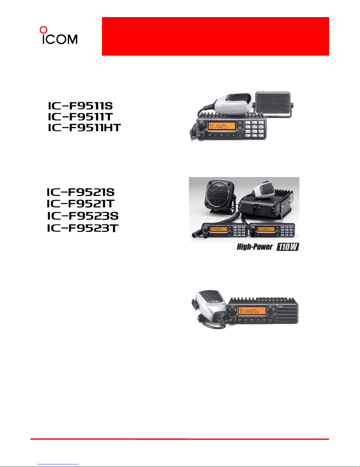
VHF P25 Trunking Mobile Transceivers
(USA Version)
(USA Version)
IC-F9511T / IC-F9521T / IC-F9523T includes
supplied Hand Microphone HM-148G and External
Speaker SP-22
(USA V
ersion
)
UHF P25
Trunking
Mobile Transceivers
(USA Version)
(USA Version)
(EXP Version)
(EXP Version)
IC-F9511HT includes supplied Hand Microphone
HM-148G and Optional External Speaker SP-30
(Photo : Double remote head option)
IC-F9511S / IC-F9521S / IC-F9523S includes
supplie
d Hand Mi
crophone
HM
-
148G
.
NOTE : In this sales handbook, the IC-F9511/S/T/HT/F9521/F9523/S/T are all referred to as “IC-F9510 series”.
When the products are described as “IC-F9511S/F9511T”, this includes IC-F9521S/F9521T/F9523S/F9523T.
5
2-2 Common Features
APCO P25 DIGITAL RADIO SYSTEM – Conventional and Trunking in one radio !
APCO Project P25 Digital migration is now an inevitable trend for Federal, State and Local government users
of 2-way radios. The IC-F9510 series, much more evolved from the IC-F1700 series, are not simply enabling
migration from analog to digital but also covers wide range of features. The standard trunking capability of
the IC-F9510 series is outstanding, ensuring smooth communication, despite busy signal traffic. Furthermore
the IC-F9510 series has the advanced DVSI AMBE+2TMenhanced vocoder resulting in clear speech audio.
P25 Conventional and Trunking
The IC-F9510 series includes P25 VHF conventional
Detachable controller (front panel)
With the optional remote control kit, RMK-2
and separation cable, the front panel controller
of the radio can be detached from the main unit. It
allows flexible installation in limited vehicle space.
Separation cable length is selectable from 1.9m
APCO 25 [P25] Digital Features
and
trunking
capabilities as standard. You can
assign individual channels to conventional analog,
conventional P25 or P25 trunking, all within one
radio.
Interoperability
The IC-F9510 series have passed CAP
(Compatibility Assessment Program) and proved to
p
rovide interoperability with other brand P25
pg
(6.2ft), 3m (9.8ft) and 8m (26.2ft).
Dot matrix, multi-function LCD
With a high-contrast dot matrix display, upper and
lower case characters can be easily distinguished.
The display shows 12 characters by 2 lines. LCD
backlight is standard.
ppy
trunked infrastructure for public safety applications.
The IC-F9510 series conforms to the standard
specifications for TIA-102, CAAB-B, Digital C4FM
Transceiver Performance recommendations.
Digital/Analog - Mixed mode operation
The IC-F9510 series have the mixed mode
operation which allows you to detect and receive
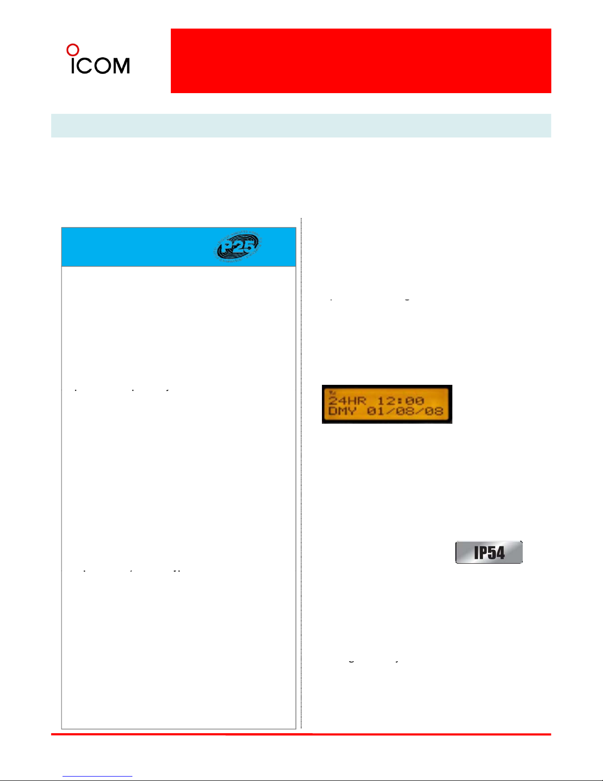
Illuminated display and keys
(Internal clock setting example)
IP54 dust-protection and splash resistance
both analog FM and P25 digital modes and to
transmit either mode depending on programming.
Individual ID and talkgroup ID
The IC-F9510 series has 100 individual ID and 250
talkgroup ID memories. Use the display to visually
select the person or group you’re going to call.
O
p
tional AES/DES encryption
(Controller only)
The rugged front controller panel is resistant
to shock and vibration. When used with the
optional separation kit, RMK-2, the controller head
has dust-protection and splash resistance,
equivalent to IP54.
See 2-3 IP Classification Code
for the meaning of this criteria.
p/yp
The IC-F9510 series provides AES and/or DES
encryption for secure conversation with the
optional UT-125 AES/DES encryption unit or UT-128
DES encryption unit. Versions certified to FIPS 1402 Level 1 for AES encryption are planned for future
release.
Enhanced vocoder ready
Built-in CTCSS and DTCS signaling
Use the built-in CTCSS and DTCS encoder and
decoder capabilities* to set up your own talk
groups, and have your radio stand by quietly when
other groups are talking. You can also set up
selective calls to individuals or control a repeater.
*Analog mode only.
6
Using the DVSI’s AMBE+2™ vocoder, the IC-F9510
series is enhanced vocoder ready.
OTAR (Over-the-Air-Rekeying)
The IC-F9510 series supports P25 OTAR function.
for changing encryption keys over the air.
gy
512 memory channels, 128 zones
Up to 512 memory channels can be divided into
128 memory zones, allowing you flexible channel
and communication group management.
Common Features
Tactical group function
The tactical group function allows you to copy
memory channels to the tactical zone and
temporarily regroup memory channels. Using the
optional zone copy cable, memory channels in the
tactical zone can be transferred from a master
radio to other radios.
Self-grounding Mic, HM-148G*
The supplied HM-148G self-grounding
microphone has a mechanism for
self grounding where a grounding wire
is no longer required.
*Supplied depending on version.
(See 3-6 Self-grounding Microphones
HM
-
148G/HM-148T for details).
HM-148G
Abundant scanning functions
The dual priority scan monitors two primary
channels alternately, while scanning other
channels. The mode-dependent scan function
automatically changes the scan list according
to the operating channel setting. The talk-back
function with timer beep, TX channel and cancel
channel settings allow you to preset the
110W of powerful RF
A full 110W of output power is available for reliable
long distance communication. A large heat sink
p
rovides effective cooling mechanism allowing
Unique Features of IC-F9511HT
transmission channel when you push the PTT
button during a scanning operation or cancel
scanning.
22W amp for Public address (PA) and RX speaker
functions
The IC-F9510 series has a built-in 22W BTL audio
amplifier. When an external speaker is connected
pgg
reliable operation (20% duty cycle transmission).
Compact “letter size” RF unit
While the IC-F9511HT provides 110W of RF output,
the RF unit dimensions are only 175 (W) × 279 (D)
× 60 (H) mm, so the IC-F9511HT can be fit into the
“letter size” console box. The controller and
to the radio, you can speak through the radio’s
microphone. The RX speaker function allows you to
relay the received audio over the speaker.
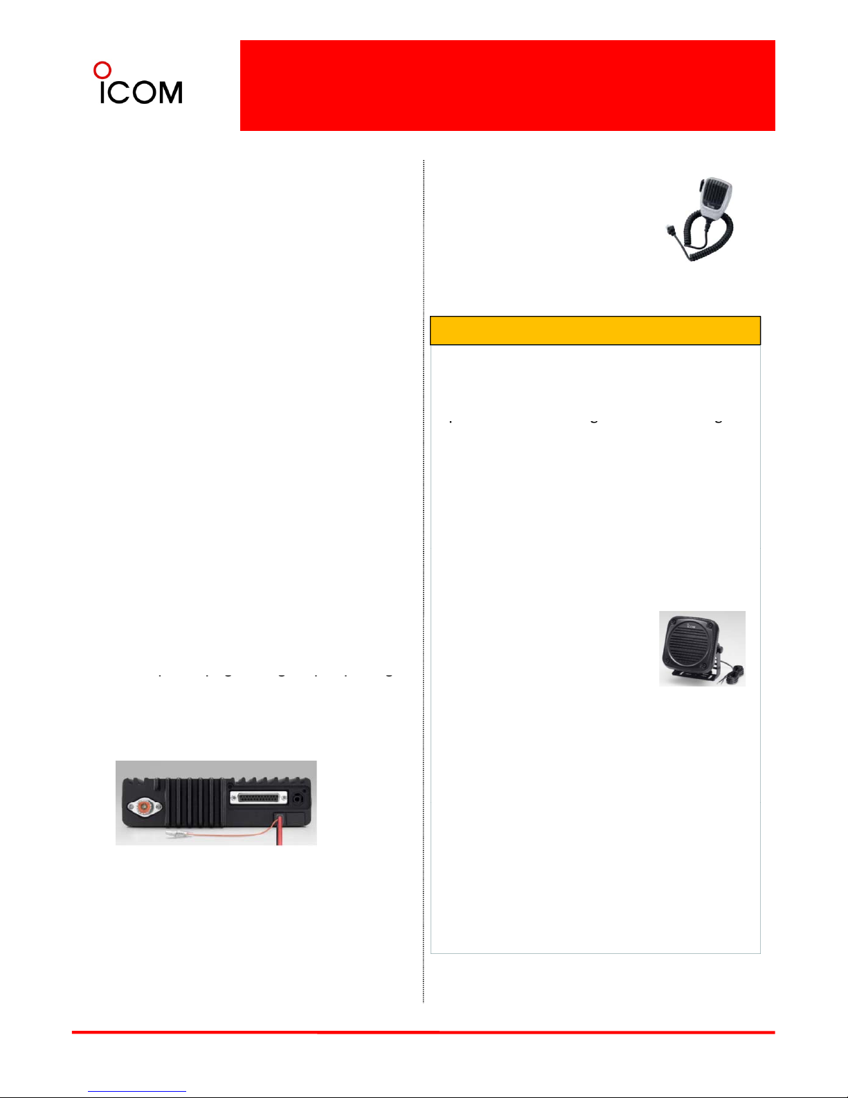
Programmable accessory connector
The IC-F9510 series has a D-SUB 25-pin ACC
connector for connecting external devices. It has
reserved
p
ins for programming to input operating
speaker are separated from the main (RF) unit for
flexible installation.
Optional external speaker SP-30
Newly designed external speaker,
SP-30 offers 15W* typ. of higher
level audio with the IC-F9511HT for
improved operation in noisy
ppg gppg
channels, turn on/off functions and output received
audio or honk a horn, etc. In addition, an ignition
sensing line allows you to control the radio power
from the engine ignition switch.
environment.
*Rated input of the SP-30 is 20W.
9-pin external speaker connector
The IC-F9511HT has a 9-pin speaker connector with
15W (typ.) BTL audio amplifier for connecting SP30 external speaker, horn honk and ignition
sensing line, etc,.
SP-30
Radio stun/kill and Power-on password function
The radio stun/kill function* disables a lost
or stolen radio over the air, eliminating security
Separate Controller
The controller and speaker are separated from the
RF unit for flexible installation. A 5m (16.4ft)
separation cable is attached to the controller and
optional separation cable length is selectable from
1.9m (6.2ft), 3m (9.8ft) and 8m (26.2ft).
7
th
reats from undesire
d list
eners.
The
power-on
password prevents unauthorized people from
turning on the radio. P25 digital mode only.
Common Features
Other features ( IC-F9510 Series )
• Wide frequency coverage
(VHF 136–174MHz / UHF 400-470MHz,
450- 520MHz)
• FM wide/narrow channel spacing*1
• Built-in audio compander*1
• Built-in inversion type voice scrambler*1
• Heavy duty microphone, HM-148
• NTIA VHF specification compliant
• Talk-around function
• DTMF autodial
*1
• Microphone hanger action (On hook scan
and off hook monitor)
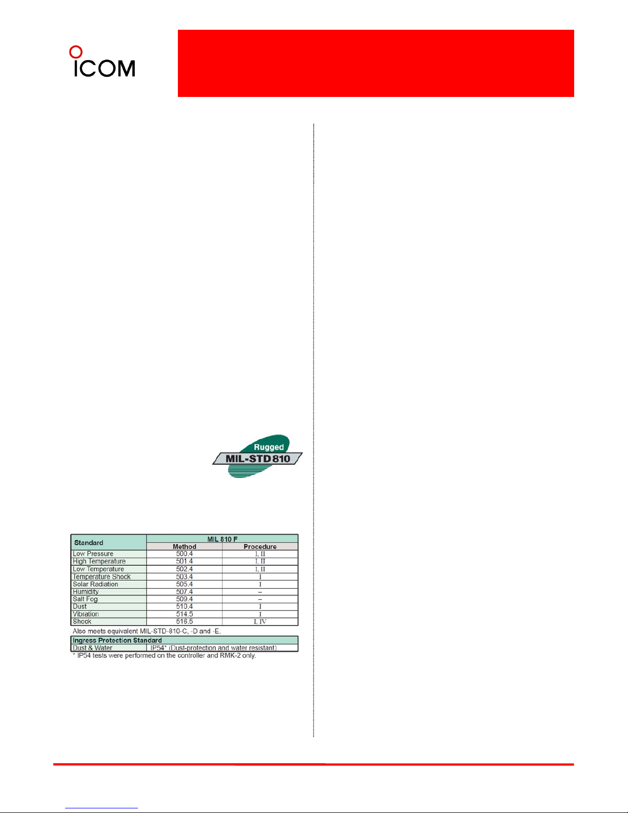
• 2-Tone encoder and decoder*1 and MDC 1200
Meets MIL STANDARD
The MIL-STD-810 series of standards are issued by
the United States Army's Developmental Test
compatible*1 (Available in the future)
*1 Analog mode only
Command, to specify various environmental tests
to prove that equipment qualified to the standard
will survive in the field
Icom makes rugged products
that have been tested to and
passed the following MIL-STD
requirements and strict
environmental standards.
Applicable U.S. Military Specifications & IP Rating
▒ Also meets equivalent MIL-STD-810-C, -D and -E.
8
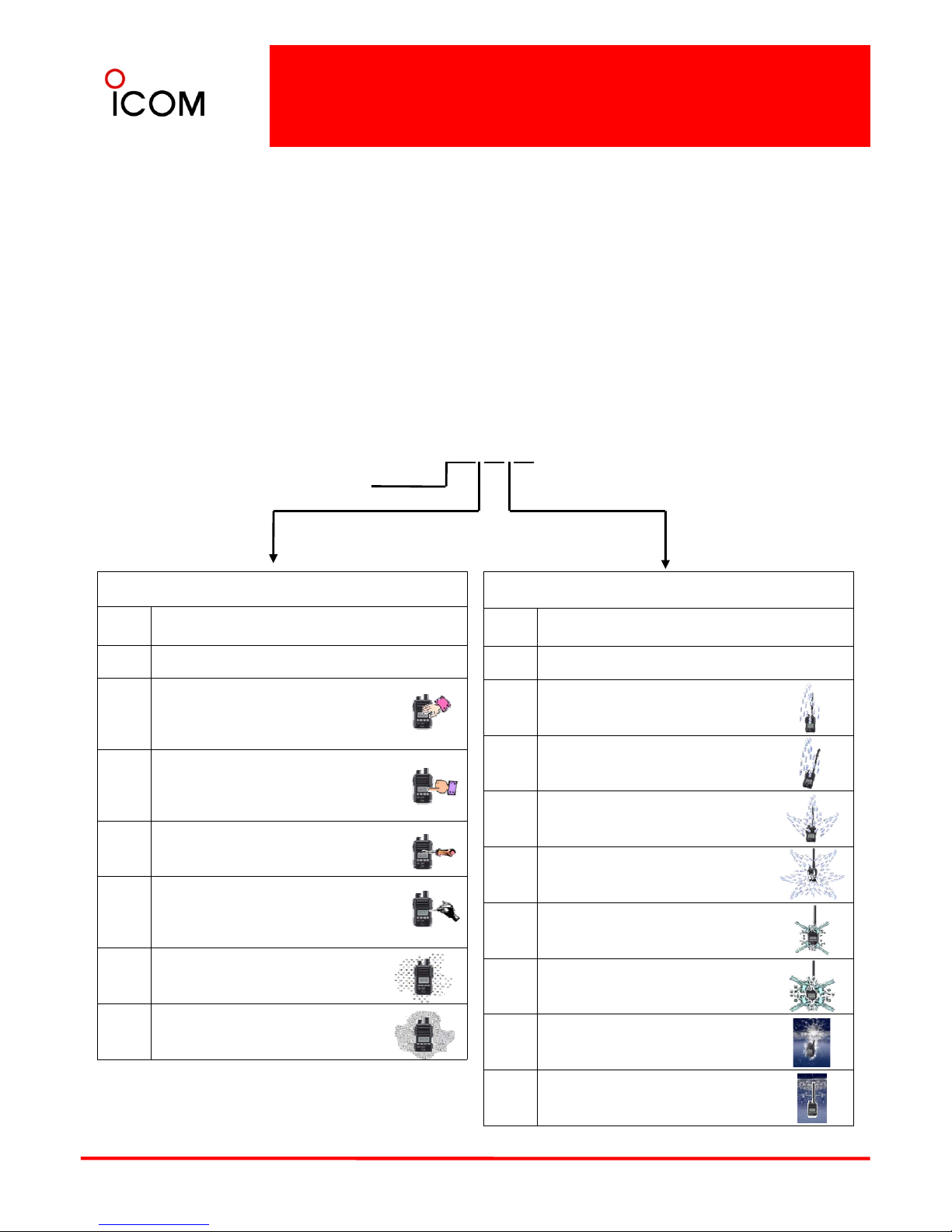
2-3 IP Classification Codes
Ingress Protection (IP) ratings are developed by the European Committee for Electro Technical Standardization.
International Standard IEC 60529 outlines an international classification system that describes the sealing
characteristics of electrical equipment. The classification system defines the level of protection provided by
enclosures to prevent the ingress of foreign objects and moisture into the electrical equipment.
The classification system uses the “IP” code, or “Ingress Protection” code, to define the level of seal. An IP
number contains two numbers (i.e. IP57) in most instances which relate to the level of protection provided by an
enclosure or housing. Either number may be shown as “X” (i.e. IPX6 / IP7X) to indicate the “X” part is not tested.
IP 5 7
Degrees of Protection (Foreign Bodies) – 1st Digit
Code letters
1st Digit
2nd Digit
Degrees of Protection (Moisture) – 2nd Digit
IP Level Description of Protection Level
0 Not protected
1
Protected against foreign solid objects
of 50 mm diameter and greater
(Protects against a large surface of the
body, such as the back of a hand)
IP Level Description of Protection Level
0 Not protected
1
Protected against vertically falling water
drops
2
Protected
agains
t f
oreign so
lid objects
of 12.5 mm diameter and greater
(Protects against fingers or similar
objects)
3
Protected against foreign solid objects
of 2.5 mm diameter and greater
(Protects against tools, thick wires, etc.)
Protected against foreign solid objects
2
Protected against vertically falling water
drops when enclosure is tilted up to 15º
3
Protected against water sprayed at an
angle up to 60º on either side of the
vertical
4
Protected against water splashed
against the component from any
direction
4
o
f 1.0 mm di
ameter and greater
(Protects against most wires, screws,
etc.)
5
Protected from the amount of dust that
would interfere with normal operation
6
Dust tight
(No ingress of dust; complete protection
5
Protected against water projected in jets
from any direction
6
Protected against water projected in
powerful jets from any direction
Protected against temporary immersion
9
against contact)
7
in water between 15cm and 1m for
30min.
8
Protected against continuous immersion
in water beyond 1m.

2-4 Project 25
What is Project 25?
Project 25 (P25) is a standard for the manufacturing of interoperable digital
2-way wireless communications products. Developed in North America under
state, local and federal representatives and Telecommunications Industry
Association (TIA) governance, P25 is gaining worldwide acceptance for
public safety, security, public service, and commercial applications.
What Are the Benefits of P25?
From the beginning, P25 has targeted four primary
What is Required for P25 Compliance?
At a minimum, a P25 radio system must provide
The published P25 standards suite is administered by the Telecommunications Industry Association (TIA Mobile and
Personal Private Radio Standards Committee TR-8). Radio equipment that demonstrates compliance with P25 is
able to meet a set of minimum requirements to fit the needs of public safety. These include the ability to interoperate
with other P25 equipment, so that users on different systems can talk via direct radio contact. The P25 standard was
created by and for public safety professionals.
objectives:
• Allow effective, efficient, and reliable intra-agency
and inter-agency communications
… so organizations can easily implement
interoperable and seamless joint communication
in both routine and emergency circumstances.
• Ensure competition in system life cycle
int
eropera
bility with th
ese mandatory
P25 Standard
components:
• The Common Air Interface (CAI) specifies how
information is coded, transmitted and received
over the air. It enables users to interoperate and
communicate digitally across networks, agencies,
and vendors.
• The Im
p
roved Mult
i
-
Band Excitation (IMBE)
procurements
… so agencies can choose from multiple vendors
and products, ultimately saving money and
gaining the freedom to select from the widest
range of equipment and features.
• Provide user-friendly equipment
’
p
()
vocoder converts speech into a digital bit stream.
Test panels judged IMBE as the coding scheme
most successful at making male and female
voices audible against background noises such as
moving vehicles, sirens, gunshots, and traffic noise
– the conditions of public safety use. DVSI has
introduced a new low data rate AMBE+2™
Vocoder that sets a new standard for high
-
quality,
…
so users can take full advantage of their radios
lifesaving capabilities on the job – even under
adverse conditions – with minimal training.
• Improve radio spectrum efficiency
… so networks will have enough capacity to handle
calls and allow room for growth, even in areas
where the spectrum is crowded and it’s difficult for
high-performance speech quality at data rates
from 2.0 to 9.6 kbps and Icom IC-F9510 series
include this AMBE+2™ enhanced vocoder.
P25 has also defined standard modes of operation to
enable multi-vendor interoperability for additional
system functions: trunking, encryption, and over-theair rekeying, to name a few.
agencies to obtain licenses for additional radio
frequencies.
What is the Status of P25 Today?
P25 systems are available today and being deployed
globally. Many organizations have mandated that new
land mobile radio system purchases follow P25
standards. P25 is ongoing -- the standard continues to
evolve as the needs of users and the capabilities of
A set of defined system interfaces allow the P25
system elements to communicate with host
computers, data terminals and the public switched
telephone network (PSTN).
Looking to the Future
There are two phases of P25 development:
• Phase 1 is completed.
10
new technology advance. Bo
th
users an
d
manufacturers have an important role to play in
shaping P25.
It
spec
ifies a 12.5 kHz bandwidth.
• Phase 2 is in development.
It will use a 6.25 kHz equivalent bandwidth to
allow better spectrum efficiency and benefit a
greater number of users
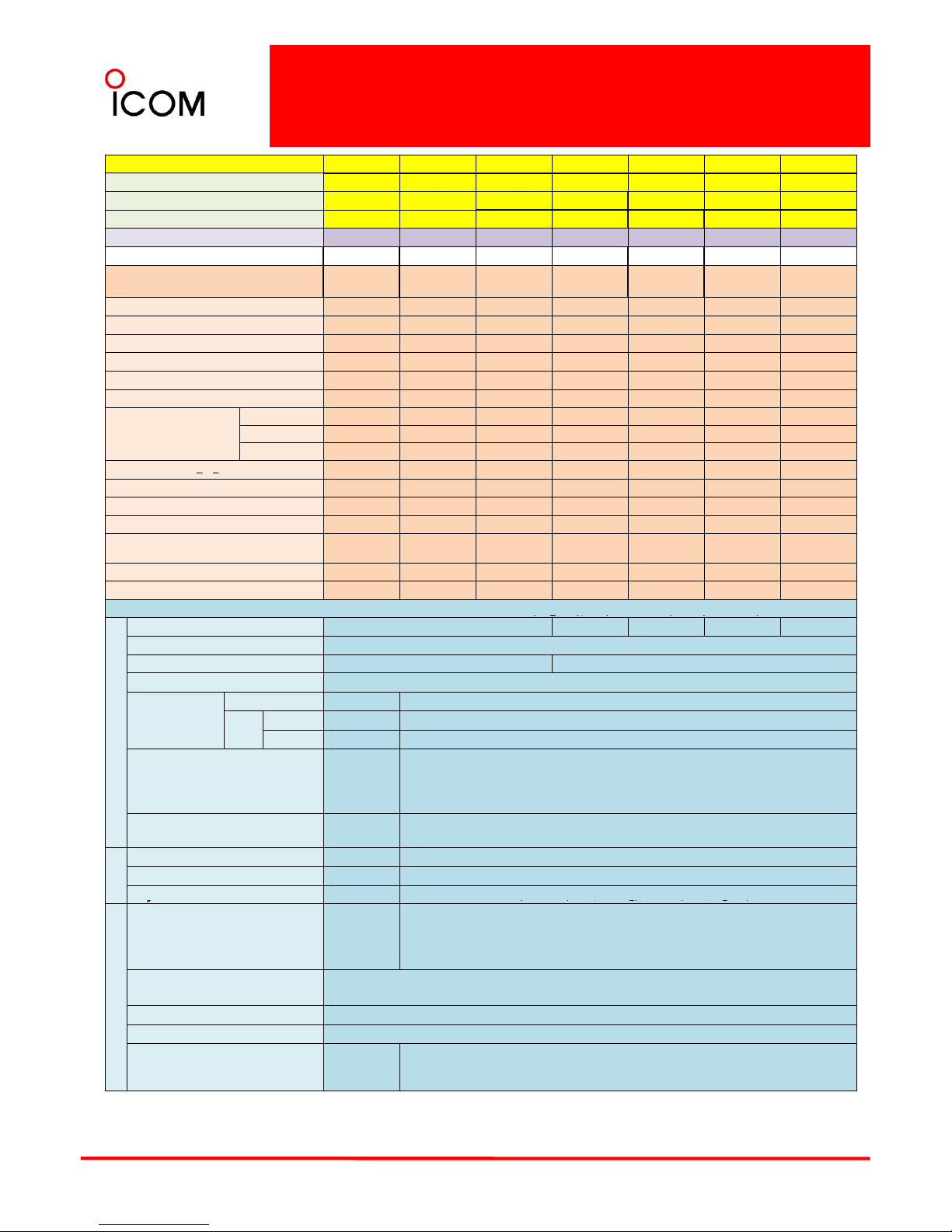
2-5 Function and Specifications
Comparison
Model No.
IC-F9511HT IC-F9511S IC-F9511T IC-F9521S IC-F9521S IC-F9521T IC-F9521T
Version #01
#01 #11 #05 #15
#01
#05
Destinations USA-01
USA-01 USA-01
USA-01 USA-01 USA-01 USA-01
Keypad or Speaker 10 keypad Speaker 10 keypad Speaker Speaker 10 keypad 10 keypad
Type Approval
FCC FCC FCC FCC FCC FCC FCC
FIPS 140-2 Certified
*1 *2
-
-
-----
Function Comparison
CTCSS
✔✔✔✔✔✔✔
DTCS
✔✔✔✔✔✔✔
✔✔✔✔✔✔✔
2-Tone
*1 -------
5-Tone ------DTMF Autodial
✔✔✔✔✔✔✔
DTMF Decoder -------
Voice Scrambler
Inversion
✔✔✔✔✔✔✔
Non rolling
-------
Rolling
-------
*
*
MDC
1200
1 2
Conventional P25 digital
*3
✔✔✔
✔✔
✔✔
P25 digital Trunking
✔✔✔
✔✔
✔✔
AES Encryption UT-125 UT-125 UT-125
UT-125 UT-125
UT-125 UT-125
DES Encryption
UT-125 or
UT-128
UT-125 or
UT-128
UT-125 or
UT-128
UT-125 or
UT-128
UT-125 or
UT-128
UT-125 or
UT-128
UT-125 or
UT-128
OTAR
*3
✔
✔✔
✔✔
✔✔
Number of Option Slot 1
11
11
11
SPECIFICATIONS
-
Measurements made in accordance with TIA-102(Digital), TIA/EIA-603 (Wide/Narrow).
( g ), /
(/ )
ENERAL
Frequency Range (MHz)
136-174
400~470 450~520 400~470 450~520
Number of Channels
512 ch / 128 zones
Channel Spacing (kHz) 12.5 (digital), 15/30 (analog) 12.5 (digital), 12.5/25 (analog)
PLL Channel Step (kHz)
2.5 / 3.125
Current Drain
Tx High
22A 11A
Rx
Stand-by
400mA 350mA
Max. audio
3.0A 1000mA
G
Dimensions (W×H×D)
(projections not included)
175×60
×
279
mm
67⁄
8
×
2
3
⁄
8
×
10
31
⁄32in
175×45×170 mm
6
7
⁄
8
×
1
25
⁄
32
×
6
11
⁄16inch
Weight (approx.)
4.7kg,10.4lb
w/controller
1.5kg; 3.3lb
TX
RF Output Power (High) 110W 50W
Spurious Emissions 70dB(typ.) 70dB (min.)
Ad
j
acent Channel Power
(W/N)
70/60dB (min.,analo
g
),
67dB (min.,digital
)
j
/(
,g
), (
,g
)
RX
Sensitivity (12dB SINAD)
0.25uV
(typ.,analog)
0.30uV
(typ.,digital)
0.25uV(typ.,analog) / 0.25uV(typ.,digital)
Adjacent Channel Selectivity
(W/N)FM(analog),P25(digital)
FM81/56dB (typ.) P25 63dB (typ.)
Spurious Response Rejection 85dB (min.)
Inter
-
modulation Rejection 78dB
(typ.)
11
AF Output Power (At 10%
Distortion with a 4 load)
15W (3%
Dist.,External
audio )
4W (typ.),22W (typ., External audio)
*1. Planned to be available in the future *2. Depending on versions. *3. OTAR function became available from
▒ the firmware Rev.1.40 on. All specifications are subject to change without prior notice or obligation.
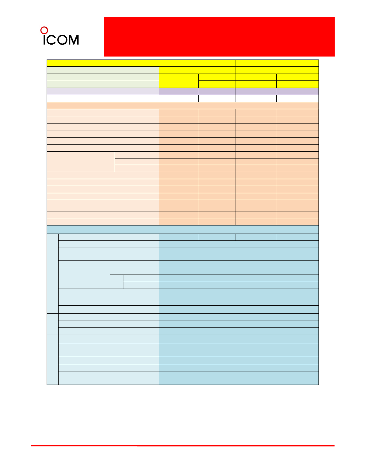
2-5 Function and Specifications
Comparison
Model No.
IC-F9523S IC-F9523S IC-F9523T IC-F9523T
Version
#06 #16
#02
#12
Destinations
EXP-01 EXP-01
EXP-01 EXP-01
Keypad or Speaker Speaker Speaker 10 keypad 10 keypad
Type Approval
-- - -
FIPS 140-2 Certified
*1 *2
-
-- -
Function Comparison
CTCSS
✔✔ ✔ ✔
DTCS
✔✔ ✔ ✔
2-Tone
*1 ----
5-Tone - - - DTMF Autodial
✔✔ ✔ ✔
DTMF Decoder - - - -
Voice Scrambler
Inversion
✔✔ ✔ ✔
Non rolling
-- - -
Rolling
-- - -
MDC 1200
*1 *2 - - - -
Conventional P25 digital
*3
✔✔✔
✔
P25 digital Trunking
✔✔ ✔ ✔
AES Encryption UT-125 UT-125 UT-125 UT-125
DES Encryption
UT-125 or
UT-128
UT-125 or
UT-128
UT-125 or
UT-128
UT-125 or
UT-128
OTAR
*3
✔✔ ✔ ✔
Number of Option Slot 1 1 1 1
SPECIFICATIONS - Measurements made in accordance with TIA-102(Digital), TIA/EIA-603 B (Wide/Narrow).
GENERAL
Frequency Range (MHz)
400~470
450~520
400~470
450~520
Number of Channels
512 ch / 128 zones
Channel Spacing (kHz) 12.5 (digital), 12.5/25 (analog)
PLL Channel Step (kHz)
2.5 / 3.125
Current Drain
Tx High
11A
Rx
Stand-by
350mA
Max. audio
1000mA
Dimensions (W×H×D)
(projections not included)
175×45×170 mm
6
7
⁄
8
×
1
25
⁄
32
×
6
11
⁄16inch
Weight (approx.) 1.5kg; 3.3lb
TX
RF Output Power (High) 50W
Spurious Emissions 70dB (min.)
Adjacent Channel Power
(W/N)
70/60dB (min.,analog), 67dB (min.,digital)
Sensitivity (12dB SINAD) 0.25uV(typ.,analog) / 0.25uV(typ.,digital)
RX
Adjacent
Channel Selectivity
(W/N)FM(analog),P25(digital)
FM81/56dB (typ.) P25 63dB (typ.)
Spurious Response Rejection 85dB (min.)
Inter-modulation Rejection 78dB
(typ.)
AF Output Power (At 10% Distortion with
a 4 load)
4W (typ.),22W (typ., External audio)
12
*1. Planned to be available in the future *2. Depending on versions. *3. OTAR function became
available from the firmware Rev.1.40 on. All specifications are subject to change without prior
notice or obligation.
3 Accessories
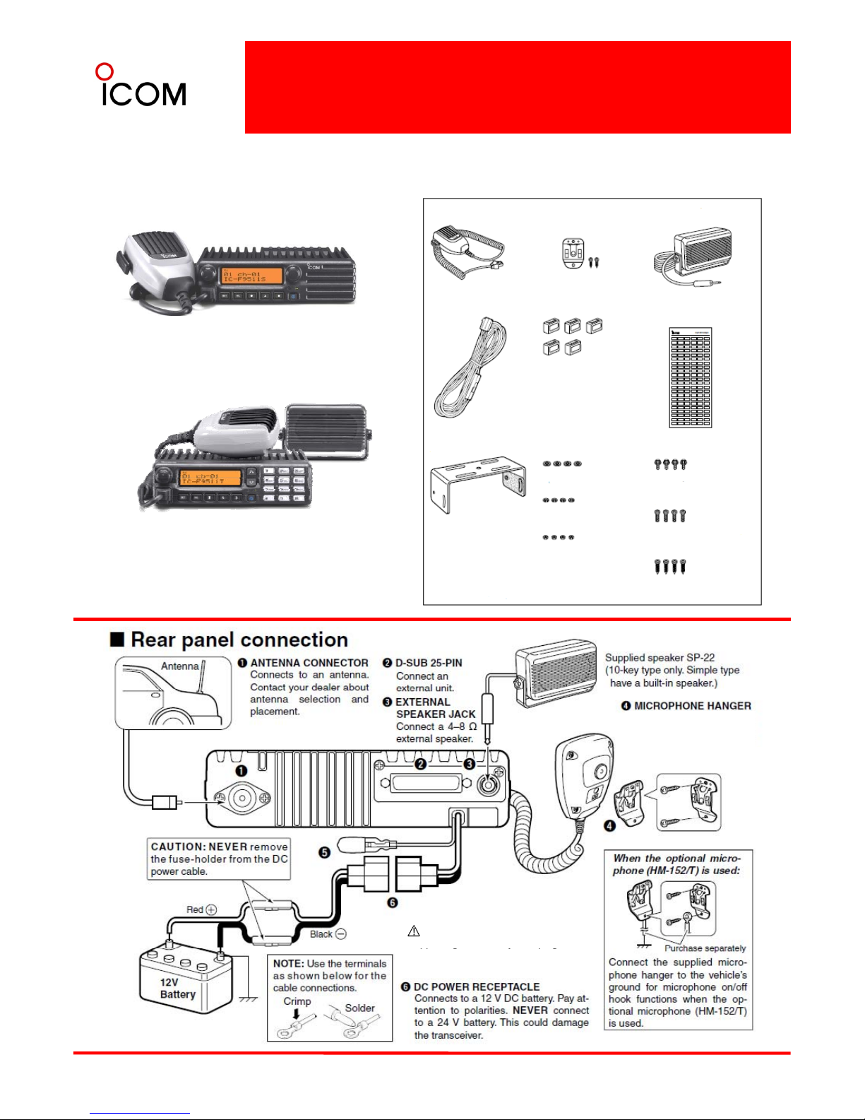
3-1 Supplied Accessories Connection
3-1-1 IC-F9511S, IC-F9511T
IC-F9511S
Supplied Accessories
Microphone
Microphone hanger
and screw set
Speaker *1
IC-F9511T
Function name
stickers *2
DC power cable
Key caps
Function name
stickers *2
NOTE : For IC-F9521/F9523/S/T, please refer
Mounting screws
(M5x12)
Mounting bracket
Flat washers
Spring washers
Nuts
Bracket bolts
*1 10
-
key type only
Mounting screws
(M5 x 12)
Self-tapping
screws (M5 x 16)
to this instruction and connect the accessories
the same way.
*2 Used for labeling the programmable
function keys according to their
assigned functions.
The supplied selfgrounding microphone can
be used for microphone
on/off hook functions.
➎ IGNITION LEAD
“DO NOT put tension on this lead.
Su
pp
orting this lead by clamping or
13
pp g y p g
taping to the DC power cable is
recommended.”
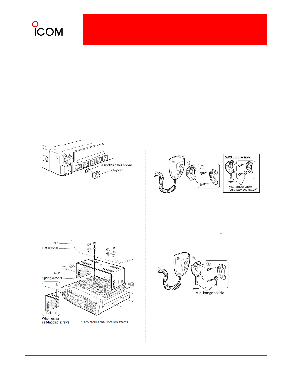
IC-F9511S, IC-F9511T
Function name stickers
There are no names on the programmable function
keys since the functions can be freely assigned to
these keys.
1 Attach the supplied function name stickers
as below to the appropriate keys for easy
■Antenna
A key element in the performance of any
communication system is an antenna. Contact your
dealer about antennas and the best places to mount
them.
recognition of that key’s assigned function.
2 Then, protect the attached stickers from
detaching with the supplied key cap as
below.
■Hand Microphone
When using with the self ground type microphone
hanger:
1 Attach the microphone hanger with screws.
2 Put on (on-hook) or take off (off-hook) the
microphone.
Mounting the transceiver
The universal mounting bracket supplied with your
transceiver allows overhead mounting.
•Mount the transceiver securely with the 4 supplied
screws to a thick surface which can support more
When using with the non-self ground type
microphone hanger:
1 Attach the microphone hanger and the
microphone hanger cable (supplied with the
than 1.5 kg
.
transceiver) with screws to the ground line.
2 Put on (on-hook) or take off (off-hook) the
microphone.
14
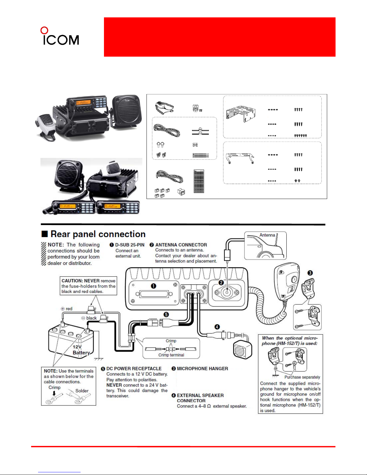
3-1 Supplied Accessories Connection
3-1-2 IC-F9511HT
IC-F9511HT
Supplied Accessories
Self-tapping
screws
Mounting screws
(M5x12)
Microphone
Spring washers
(M5)
Black and red cables
with fuse holder
Mounting bracket for
main unit
Microphone hanger
and screw set
Flat washers
(M5)
DC power cable
Mounting screws
(M5x12)
Self-tapping screws
(M5x16)
(M5x16)
Mounting screws
(M5x12)
Socket terminals
Nuts (M5)
Bracket bolts
Mounting bracket for
controller
Flat washers
(M5)
Spring washers
(M5)
Nuts (M5)
Self-tapping screws
(M5x16)
Bracket screws
Function name s
tickers *2
Fuses *1
Separation cable
Crimp terminals
Cable ties
Mounting screws
(M5x12)
▼Two front panels for one box available
*1 Fuses should be installed in the fuse holder of the black and red cables, respectively.
*2 Used for labeling the programmable function keys according to their assigned
functions.
Hous
ing
Key
caps
Key
caps
Housing
The supplied self-grounding
microphone can be used for
microphone on/off hook functions.
15
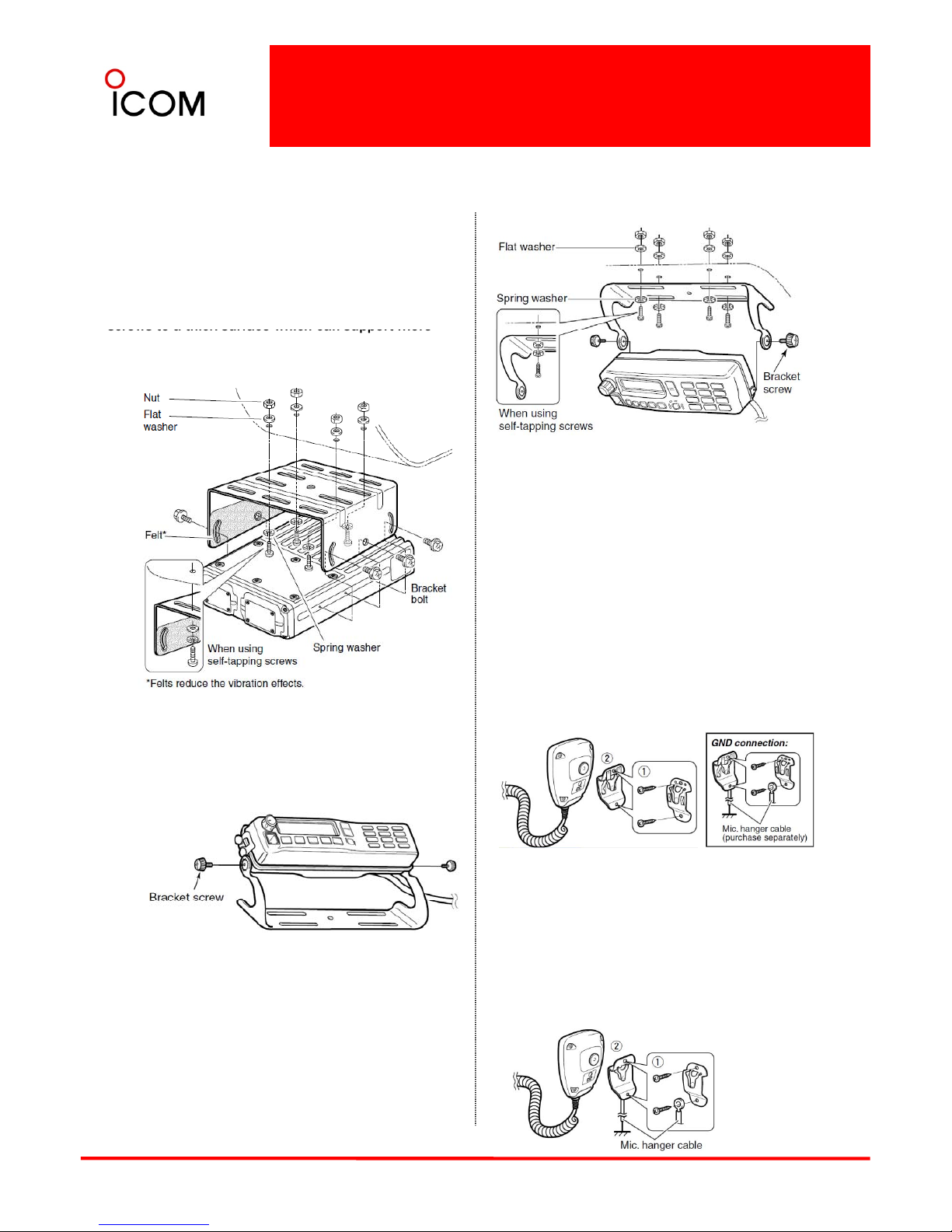
IC-F9511HT
Mounting the transceiver
Main unit
The universal mounting bracket supplied with your
transceiver allows overhead mounting.
• Mount the main unit securely with the 4 supplied
screws to a thick surface which can support more
than 8 kg (17.63 lb).
■Antenna
A key element in the performance of any
communication system is an antenna. Contact your
dealer about antennas and the best places to mount
them.
■Hand Microphone
Controller
2 types of mounting styles are available—one is
When using with the self ground type microphone
hanger:
1 Attach the microphone hanger with screws.
2 Put on (on-hook) or take off (off-hook) the
microphone.
overhead mounting, and other one is on-board
mounting.
When using with the non-self ground type
Overhead mounting
• Mount the controller securely with the 4 supplied
screws to a thick surface which can support more
microphone hanger:
1 Attach the microphone hanger and the
microphone hanger cable (supplied with the
transceiver) with screws to the ground line.
2 Put on (on-hook) or take off (off-hook) the
microphone.
16
than 2 kg (4.40 lb). (Overhead mounting)
IC-F9511HT
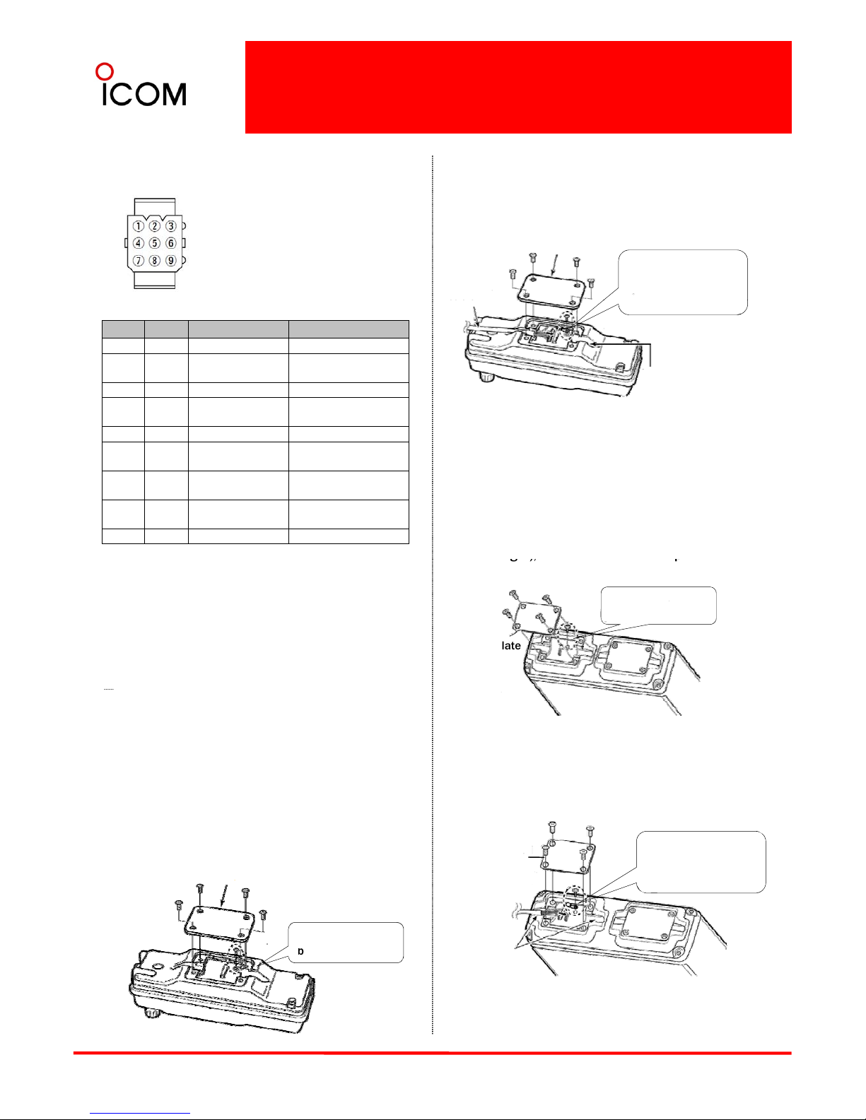
Speaker connector information
’
When the horn function is
activated, HORN1 and
HORN2 are shorted.
2
Connect the separation cable to the controller as
shown below.
• The cable can be inserted into either the left or
right grooves as desired.
Rear plate
Screw the removed
circuit board screw in
step 1 to connect the
Separation
cable
Pin No.
Name Description Specifications
①
IGN IGSW cont. In 0 -Vcc
②
RXSP1 RX AF Out (BTL)
Output power : Max.20W
Impedance : 4
③
NC - -
④
HORN1 Horn drive cont.Out 0-VCC
Connector s front view
Cable groove
Controller
cable terminal.
cab e
⑤
HORN2 Horn drive cont.Out 0 -Vcc
⑥
RXSP2 RX AF Out (BTL)
Output power : Max.20W
Impedance : 4
⑦
PS1 AF Out to PA (BTL)
Output power : Max.20W
Impedance : 4
⑧
PS2 AF Out to PA (BTL)
Output power : Max.20W
Impedance : 4
⑨
GND Connects to ground. -
3After the cable connection, replace the removed
rear plate and the 4 screws, then connect the
opposite side of the separation cable to the main
unit.
Main unit
1Unscrew the 4 screws of the front plate (either the
left or ri
ght),
then remove the front plate from the
Separation cable connection
CAUTION: To avoid damage to the transceiver,
disconnect the DC power cable from the
transceiver before connecting the separation
cable.
NOTE: The following connections should be
g), p
main unit.
Front plate
Unscrew the circuit
board scew.
performed by your Icom dealer or distributor.
The supplied or optional separation cable is
required for the controller and the main unit
connection.
For the details on the separation cables,
see 3-5 Optional Accessories.
2Connect the opposite side of the separation cable
that is connected to the controller described on
the previous page as shown below.
• The cable can be inserted into either the left or
right grooves as desired.
Main unit
Controller
1Unscrew the 4 screws, then remove the rear
plate from the controller.
Rear plate
Unscrew the circuit
Front plate
Screw the removed
circuit board screw
in step 1 to connect
the cable terminal.
Separation
cable
17
3After the cable connection, replace the removed
front plate and the 4 screws, then connect the DC
power cable.
b
oard screw
Controller
Cable grooves
Main unit

3-2 Mobile Radio Installation
¾ ANTENNA
Many types and sizes of antennas are available,
whatever you choose you need to consider some basic
points :
Check points
The locations to
obtain
Check if there are installation
instructions available for your
car.
Vehicle
manufacturer
or agent.
¾ PREPARATION
Check points Potential action
Reduce any RF interference Position the antenna
¾ POSITION
Checklist of points to decide before starting:
1) Is there a suitable position to mount the radio?
Check that radio is suitable and
approved for mobile installation
Radio manufacturer
or agent.
Read the installation instructions
for the radio.
to the vehicle electronic
circuits.
away from any sensitive
circuits.
If the transceiver is a “high
power” model, reduce RF risk
to pedestrians etc.
Position the antenna
where pedestrians will
not easily touch it or
stand too close.
Avoid mounting the antenna Position the antenna
2) Will you use a hand mic or a “hands-free”
installation?
3) Can you route all cables so that they will not
interfere with any controls of the vehicle? Hand mic
cables are especially important here.
4) Make sure that it is possible to securely mount the
radio.
5) Will the position of the radio be safe for you and
Don’t forget that the antenna must also be securely
where it could be dangerous
for pedestrian or other road
users.
away from the edges of
the vehicle, as high as
possible.
Avoid having the
antenna tip at “eye
level.”
your passengers
?
6) Will the position of the radio obstruct any safety
device of the vehicle?
7) Don’t forget that transceivers can become hot in
transmit mode and ventilation should not be
obstructed.
8) Don’t mount the transceiver, antenna or
accessories where they can obstruct the driver’s
mounted to the vehicle and should be a sensible size.
If you choose a magnetic mount type, be sure that it is
rated for the antenna type.
¾ CABLING
Mobile transceivers generally need a direct connection
to the vehicle battery.
You need to check where you can route the DC supply
view
.
¾ VEHICLE
Some vehicles require special attention.
These notes are written for petrol/diesel engined cars,
vans etc. with 12 volt battery supplies.
Other types of vehicles may be subject to special
regulations.
cable an
d RF
coaxial cables.
If there are no specific instructions for your vehicle
and/or radio then the following points should be
adhered to :
1) Keep the radio cables away from fuel or gas pipes.
2) Keep the radio cables away from any part that will
become hot.
If in doubt, please contact either the vehicle or radio
distributor for further information.
Be sure that the installation can be made safely, such
as no petrol leaks etc.
Modern vehicles are using more and more non-metallic
materials in their construction. Some panels (interior
and exterior) may be made from plastic or reinforced
3)
Keep the radio cables clear of moving parts
(steering, suspension, throttle control, etc.)
4) Route the cables where they can be securely held
in position.
5) Check if you need to drill some holes for passing
radio cables. (Before drilling holes, check for
hidden radio or power wiring.)
6) Only attach cables to non-moving parts of the
18
resin etc. Such panels do not have the same shielding
properties as metal and this may cause unexpected
effects with RF such as high VSWR or RF exposure. A
qualified radio installation engineer should be able to
give you advice on suitable products that can be used
to “screen” such non-metallic panels if required
vehicle
.

Mobile Radio Installation
¾ INSTALLATION
Start the installation with any mechanical work that is
required for fitting the radio mount, cables, etc.
Before drilling any hole in a vehicle check exactly what is
behind the panel that you are drilling. When drilling a
hole always use a drill with a “stop” so that it is
impossible for the drill to go too far. Take extra care to
avoid petrol tanks and pipes, brake lines, other wiring,
Switch on ignition (but not engine) and check that all
instruments, warning lights etc are displaying “normal”
readings. Now transmit and verify that nothing changes
and that no instrument is disturbed. If the transceiver is
multi-mode, then repeat the test with all modes. If the
transceiver is multi-band, then repeat the test in all
operating bands. In each case use the maximum RF
power. If there is ANY disturbance of the vehicle
etc.
If
you have to dr
ill
any hole to pass a cable
then the
hole must be sealed with a rubber grommet and when
the cable has been passed through you should re-seal
the cable and grommet with a suitable sealant.
If you drill holes for mounting screws, be sure to check
that the screw is a suitable type and length.
Locking type screws, nuts or washers are preferred.
inst
rumentation
then stop and identify the
source o
f
the problem before continuing.
If the above tests have been completed without any
problems, you can proceed to the STATIC operational
checks.
¾ STATIC OPERATIONALCHECKS
Pay attention to cables inside the passenger
compartment. They should be secured or routed under
carpets etc. There should be no possibility that they
could move and interfere with any control or pedal.
¾ BATTERY CONNECTION
Mobile transceivers are usually intended for direct
connection to the battery. Before disconnecting the
Start the engine of the vehicle and repeat ALL the tests
described in ‘TESTING’. Check that there is no
disturbance of the engine control or engine speed.
With the help of an assistant, switch on the vehicle
lights, indicators, etc. while transmitting. Check that no
unintended flashing or indication occurs.
Stop the engine. If the above checks have been
battery you need to be aware of some possible
problems:
1) Is the vehicle fitted with an alarm that may not
operate after re-connection?
2) Is the vehicle fitted with any electronic circuit that
may malfunction after re-connection? (engine
management, traction control, braking control, etc.)
completed without any problems you can proceed to
the mobile operational checks.
¾ MOBILE OPERATIONALCHECKS
DO NOT PERFORM THESE CHECKS IN CITY TRAFFIC!
Find a quiet road, start the vehicle and while moving
slowly operate the transmitter. Check that brakes, etc.
all operate as normal. Repeat using all bands, modes,
3)
If in doubt do not disconnect the battery. Take the
vehicle to an authorized service agent and ask them
to connect the transceiver power cables for you.
If the DC cables are not long enough they should only be
extended using an equivalent size and type of cable and
must be capable of handling the specified current and
be well insulated. Always try and route cables so that the
etc. as applicable to your transceiver. If all is OK, then
increase to normal driving speed and repeat the tests.
If there is any unexpected reaction from the vehicle
(accelerator, transmission, steering or other in-car
electronic device) then stop immediately and seek
assistance from a qualified installation engineer before
operating the transceiver. If all is OK, perform a final
braking test at normal speed while transmitting.
total length is as short as possible.
Connections should be made to the battery terminal
connectors and nowhere else in the vehicle wiring.
¾If the vehicle uses a different battery voltage (24 volts,
etc.) then a DC-DC convertor must be used. Never try and
connect to an intermediate point on the battery, etc.,
that appears to measure 12 volts.
Finally stop the vehicle, switch OFF the transceiver and
recheck your installation :
• Nothing has come loose?
• No equipment or cable was inconveniently placed
for your driving or your passenger’s safety?
• Vehicle alarm/immobilizer functions correctly?
• All vehicle instruments read normally?
19
¾ TESTING
Switch on transceiver and check that it functions OK.
Check the antenna matching with a VSWR meter, if
possible, adjust the antenna for a minimum value.
(Don’t forget that doors etc may have an effect on the
measured value!)
WARNING !
If the vehicle and transceiver installation does not pass
every check without problem you should seek expert
assistance.
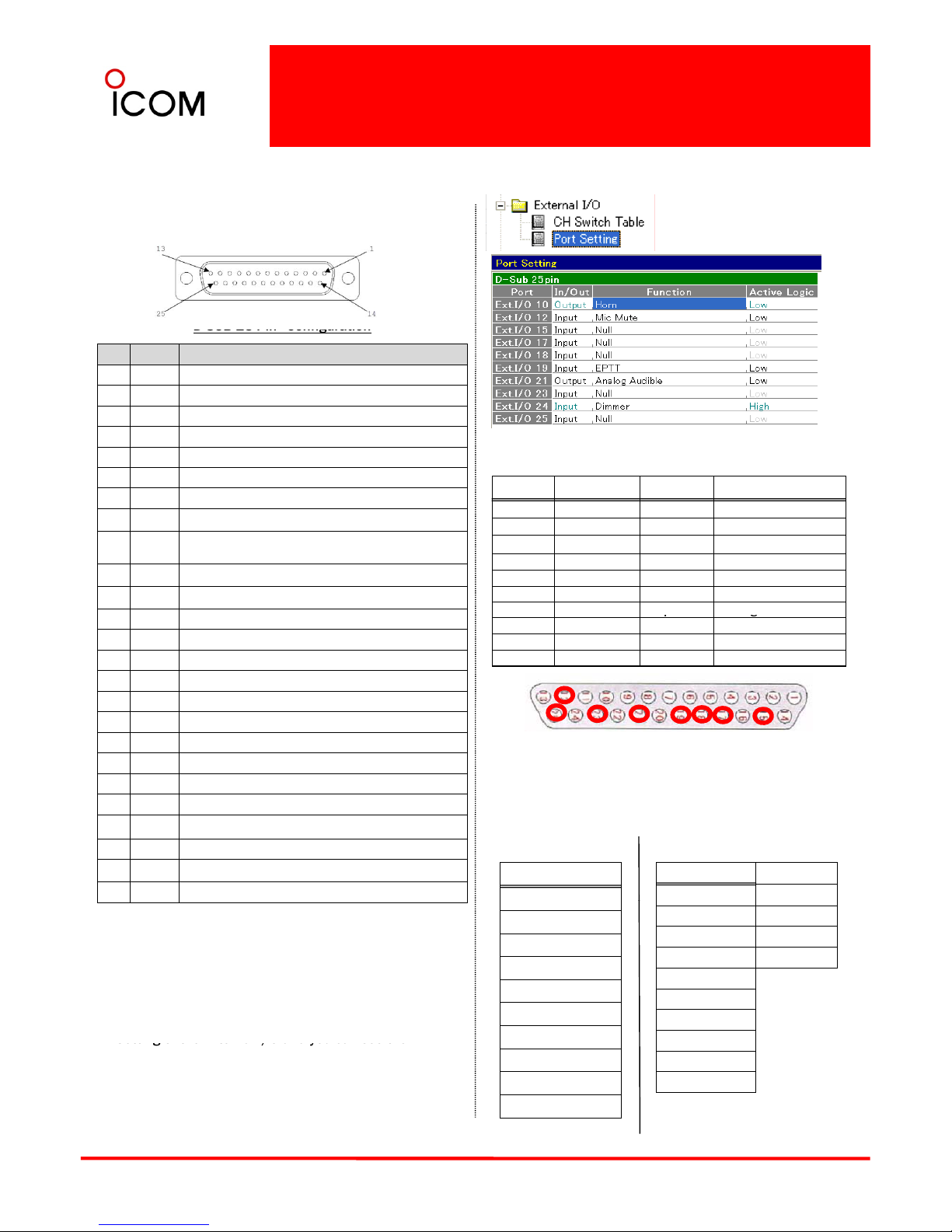
3-3 D-Sub 25 Pin Configuration
D-sub accessory connector
The IC-F9511 series has a D-SUB 25 pin ACC
connector for connecting various external devices.
D
SUB 25 Pin
Configuration
Pin No. Pin Name Description
1 H_OUT2 22W Hi Power AMP BTL Output
2 TXD Serial Data Output *Built-in RS-232C Interface
3 RXD Serial Data Input *Built-in RS-232C Interface
4 RTS Request To Send Input for Internal RS-232C Interface
5 CTS Clear To Send Input for Internal RS-232C Interface
There are 8 pins that can be assigned the function
you need. These are the default setting of 8 pins.
6 DSR Connected to Pin20
7GND Ground
8 EXMOD Modulation Input
9
DISC
OUT
Demodulation Signal Output
10 HORN Horn Selection Signal Output
11 VCC DC Voltage Output
Port No. Port set No. In/Out Function
10 - Output Horn
12 PIN01 Input Mic Mute
15 PIN02 Input 17 PIN03 Output Busy
18 PIN04 Output Digital Audible
19 PIN05 Input EPTT
21 PIN06 Out
p
ut Analog Audible
12 PI01 Port setting (MIC Mute Input )
13 H_OUT1 22W Hi Power AMP BTL Output
14 GND Ground
15 PIO2 Port setting
16 NC No connection
17 PI03 Port setting
18 PI04 Port setting
p
g
23 PIN07 Output Mic Mute
24 - Input Dimmer
25 PIN08 Output Hanger
12
15
171819212325
19 PI05 Port setting (EPTT Input)
20 DTR Connected to Pin6
21 PI06 Port setting (Analog Audible Output)
22 PA AF Amp Signal Input
23 PI07 Port setting
24 DIMO DIMMER Control Input
25 PI08 Port setting
Function
Function
Null P2 Monitor
Th
ese defau
lt settings
can be change
d to the f
unction
you want. 1 Select Input or Output at In/Out.
2 Select the function you need.
Input
Output
Null
MCH Select : 1
MCH Select : 2
MCH Select : 3
MCH Select : 4
MCH Select : 5
Mic Mute
Busy P3 Monitor
Analog Audible P4 Monitor
Digital Audible Ext.CH Mode
Mic Mute
Hanger
TX
The pins (No. 12, 15, 17, 18, 19, 21, 23 and 25 ) can be
customized to your required function in cloning
software.
Please set up the cloning software and proceed to Port
20
EPTT
Dimer
Ext.Key
Horn
P0 Monitor
P1 Monitor
Setting of the External I/O and you can see the
following Port Setting Window.
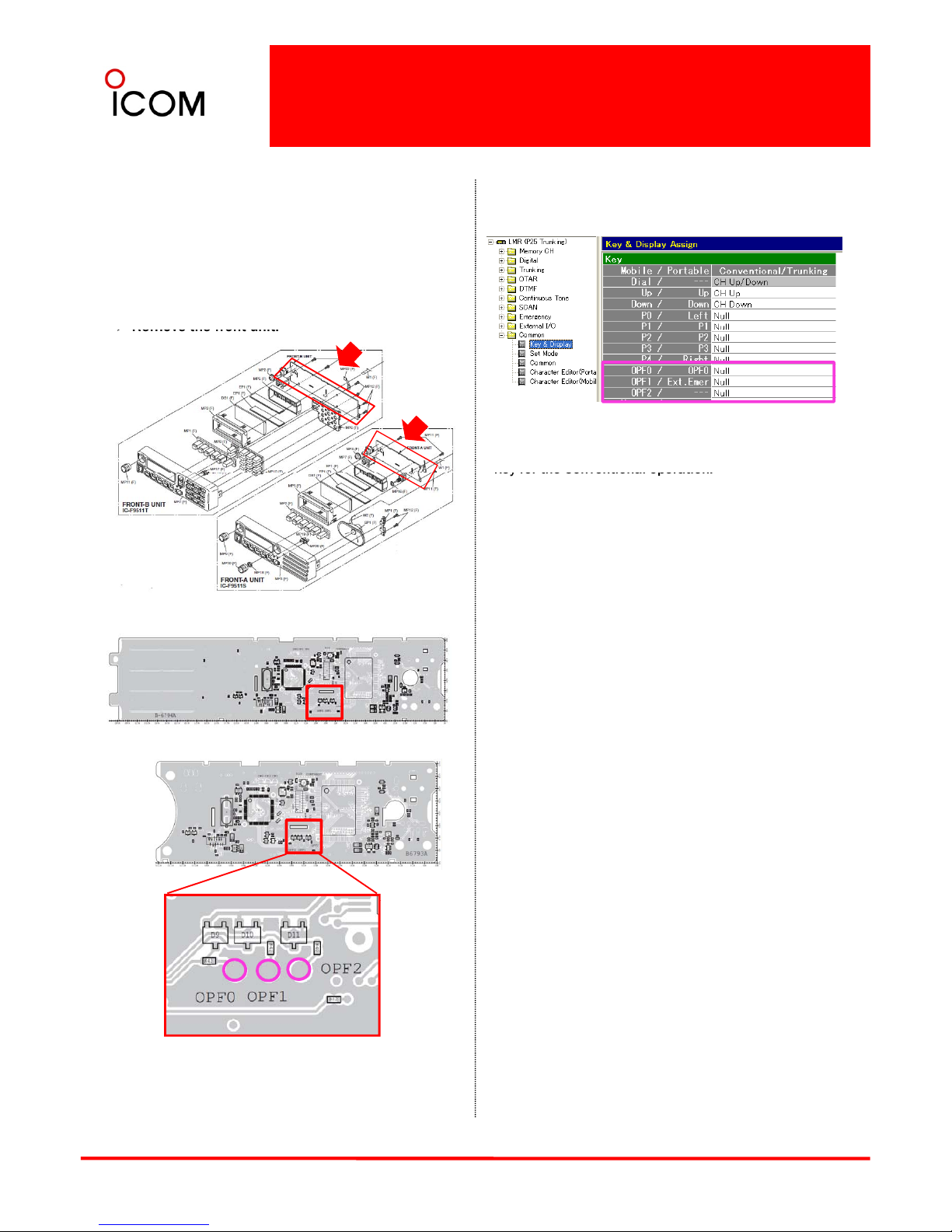
3-4 Additional Function Keys
Additional Function Keys
Three programmable function keys can be
installed externally. – OPF0 / OPF1 / OPF2
To activate the assigned functions in these
buttons, soldering is required.
¾ Program a desired function with the cloning
software as shown below.
Front A Unit
Assign one of these functions to each programmable
IC-F9511T
¾
Remove the front unit.
Front B Unit
key for the Conventional operation.
Null
CH Up / CH Down
Zone
Scan A Start/Stop, Scan B Start/Stop
Scan Add/Del (Tag)
Prio A, Prio A (Rewrite), Prio B, Prio B (Rewrite)
MR-CH 1/MR-CH 2/MR-CH 3/MR-CH 4
IC-F9511S
Moni
Public Address
RX Speaker
Light
Lock
Lone Worker
High/Low
Talk-around
Front A Unit (IC-F9511T)
Front B Unit (IC
-
F9511S)
DTMF Autodial
Re-dial
Emergency/Surveillance/Scrambler/Encryption
Scrambler/Encryption
Compander
Hook Scan
User Set Mode
OPT1 Out/OPT2 Out/OPT3 Out
OPT 1 Momentary/OPT2 Momentary/OPT 3 Momentary
Ext.CH Sel Mode
Digital Button/Digital Page
Digital Status/Digital Message
Phone
Individual/Talk-group
Zeroize
Rekey/Keyset
21
Sp.
Func
1/SP.Func 2/Site Lock/Site Select
Clock
Home
¾ Solder the circulation of OPF0, OPF1, and OPF2
shown above to activate the function.
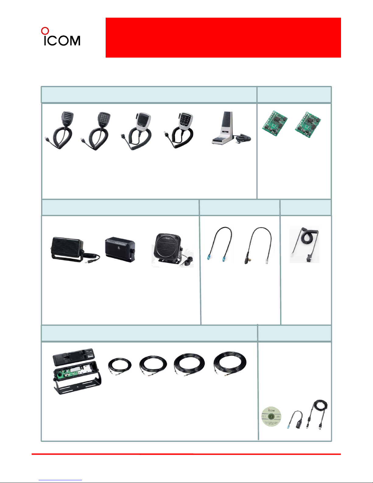
3-5 Optional Accessories
MICROPHONES
Current options available are shown below. (Some options are not available for all countries.)
ENCRYTION UNITS
HM-152
Regular hand
microphone
HM-152T
DTMF
microphone
HM-148G
Heavy duty
microphone
(Self-ground)
SM-25
Convenient for
dispatching,
equipped with
UT-125
AES/DES
Encryption
Unit
UT-128
DES
Encryption
Unit
HM-148T
Heavy duty
microphone
With DTMF
EXTERNAL SPEAKERS
ZONE COPY CABLE
monitor switch
,
Desk top.
KEYLOADER CABLE
keypad
(Self-ground)
OPC-1532
Mobile to
mobile
OPC-1871
Mobile to
handheld
SP-22
Compact and
easy-to-install.
SP-10
Compact mobile
speaker.
SP-30
External
speaker for
OPC-1534
Keyloader
Cable (to KVL
SEPARAION CABLES
zone copy
cable
zone copy
cable
SEPARAION KIT
CLONING SOFTWARE
Same as
supplied with
IC-F9511T
IC-F9511HT
3000 Plus by
Motorola )
RMK-2
OPC-607
(3m; 9.8ft)
OPC-608
(8m; 26.2ft)
OPC-609
(1.9m; 6.2ft)
CS-F9511 #01 EXP
:
For programming all
versions of the IC-F9510
series.
Cloning cables :
OPC-1122U (packed
with
OPC-1637 USB cable and
USB driver CD)
OPC-726
(5m; 16.4ft)
22
For front panel
detachment
installation.
OPC-1122U OPC-1637
USB
driver
3-6 Self-grounding Microphones
HM-148G / HM-148T
The HM-
148G and HM-
148T,
H
eavy duty se
lf
-
grounding microphones are designed to do without
connecting wires to the vehicle’s ground. The selfgrounding is enabled by a newly designed
microphone hanger.
HM-148G
(Plain type)
HM-148T
(DTMF type)
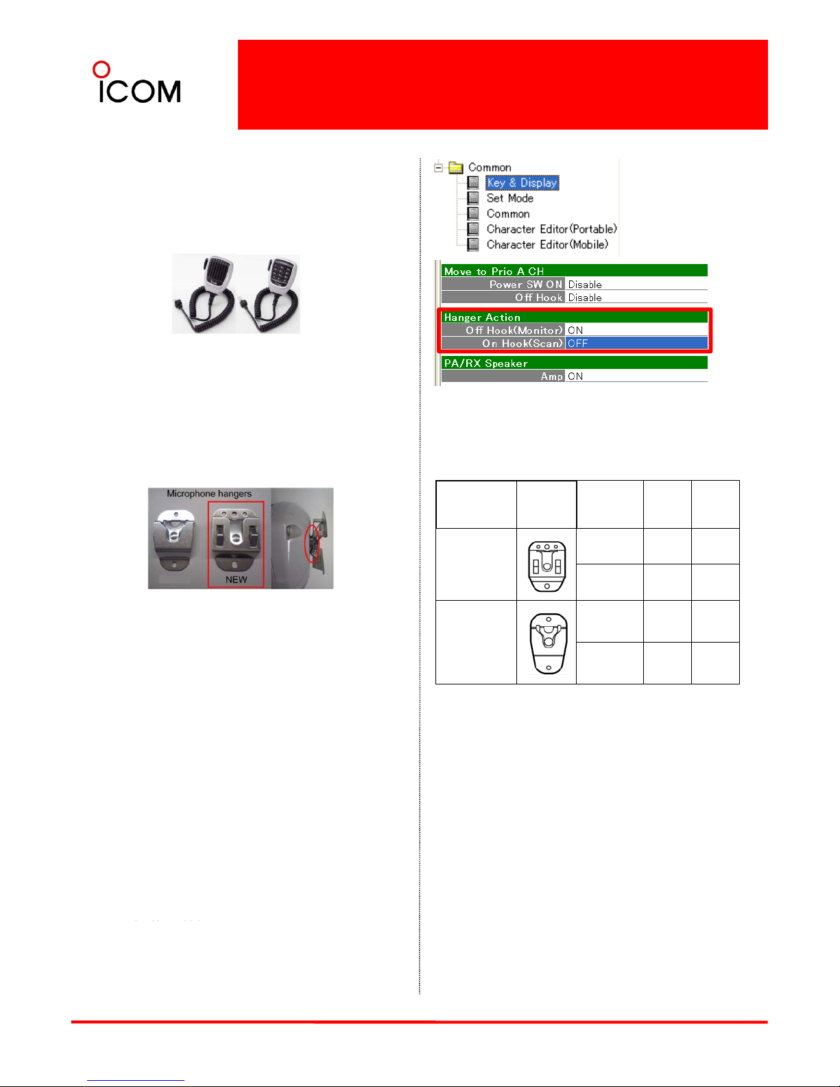
Features
1. Self-Grounding
“Hanger Action” functions can be used without
connecting the microphone hanger to the
vehicle’s ground, which makes the installation
work easier.
Hanger Type Image
GND
connection
HM-148
G/T
HM-148
HM-152
HM-152T
Availability of Hanger Actions
The available On-hook/Off-hook hanger actions
are shown below. ( : Available N/A : Not
available)
When the HM-148G/T is put on the new selfgrounding hanger, the microphone’s metal parts,
having no conduction between them in normal
condition, short-circuits. Thus, no ground wiring is
"
OLD
Self grounding
supplied with
the HM-148G/T
C
onnected
Not
Connected
*
N/A
Non-self
grounding
supplied with
the transceiver
Connected
Not
N/AN/A
2. “Hot DTMF” for HM-148T
The DTMF code will be sent out when pressing a
key without a PTT operation.
*This function can be de-activated too.
required. The radio detects it also as
Hanger
Action".
Connected
/
/
* Self-ground
NOTE
• HM-148G #18 EXP / HM-148 #19 EXP includes a
self-grounding mic hanger. (The former versions do
not include the mic hanger, so it’s necessary to
Hanger Action (On Hook / Off Hook)
There are two “Hanger Action” functions
available. It can be pre-set ON or OFF in the
cloning software.
1. Off Hook Monitor function
When you pick up the microphone out of the
hanger, the radio automatically turns to the
order it separately.)
• When you use other microphones than HM-148G
/HM-148T with the new microphone hanger,
the hanger must be connected to the vehicle’s
ground for using hanger action functions.
• When you use the HM-148G/HM-148T
23
monitor mode.
2. On Hook Scan function
When you put the microphone on the hanger and
the radio automatically starts scanning.(The
radio continues to be on the scan mode except
when you talk on the radio.)
with an old, regular type microphone hanger,
ground wiring is still required.
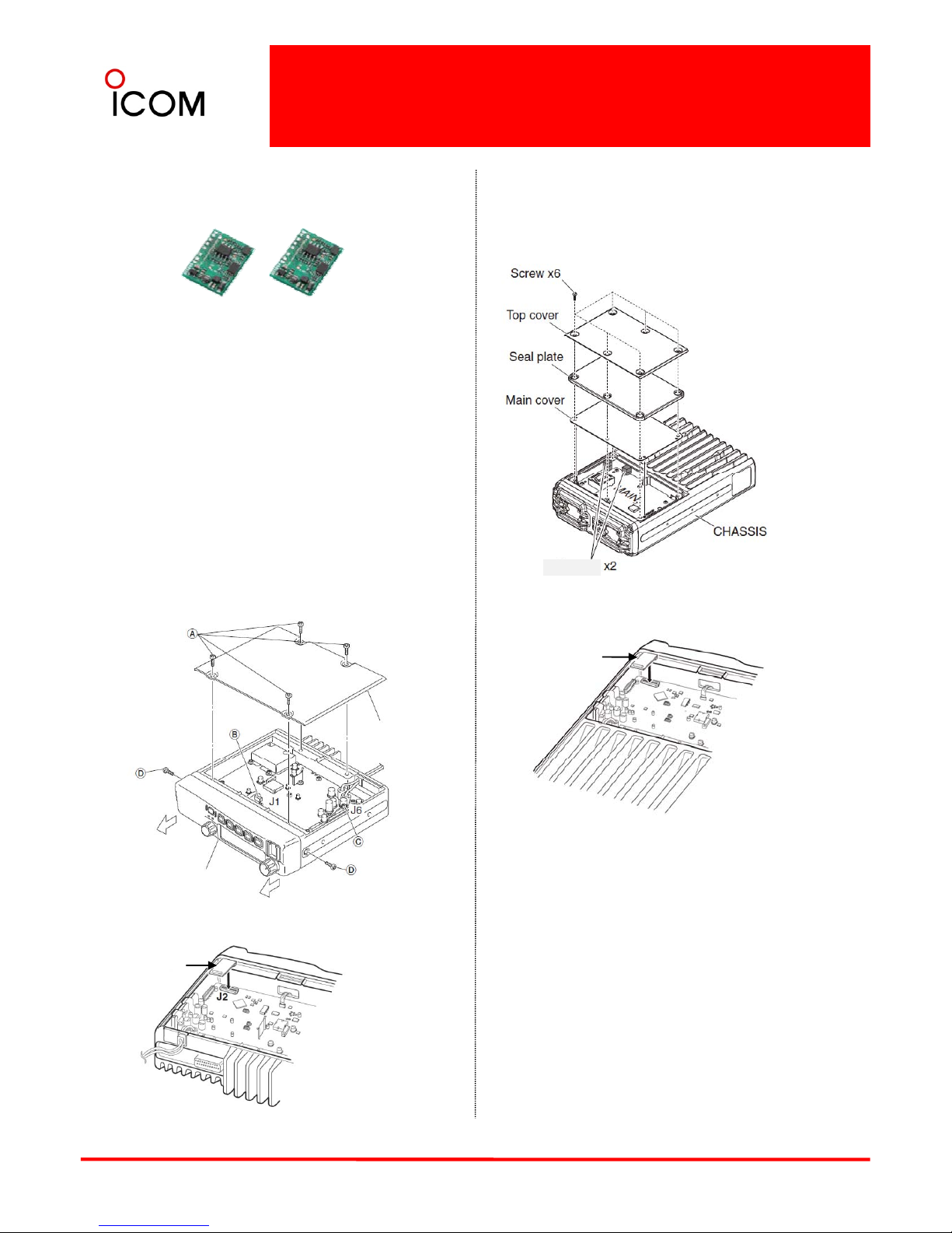
3-7 Optional Internal Unit Installation
¾
IC-F9511HT
1Unscrew 6 screws from the top cover, and remove
the top cover, seal plate and main cover.
2Remove 2 cushions from the MAIN UNIT.
This is the instruction on how to install the UT
-
125,
UT-128 encryption unit to the transceiver.
UT-125 UT-128
CAUTION! Optional unit installation should be done
at an authorized Icom service center only.
ENCRYPTION UNIT INSTALLATION
AES/DES
Encryption
Unit
DES
Encryption
Unit
3Attach the unit as illustrated below.
¾ IC-F9511S, IC-F9511T
1Unscrew 4 screws, A, then remove the bottom
cover.
2Unplug J1(B) and J6 (C; F9511S only).
3Unscrew 2 screws, D.
4Remove the front panel in the direction of the
arrows.
Cushion
UT-125
or
UT-128
Bottom cover
4Recover the transceiver, and set or modify the
setting using optional cloning software.
These instructions on how to install the units can
Front panel
(F9511S only)
be referred to in the service manual .
5Attach the unit to "J2" as below.
24
6Recover the transceiver, and set or modify the
setting using optional cloning software.
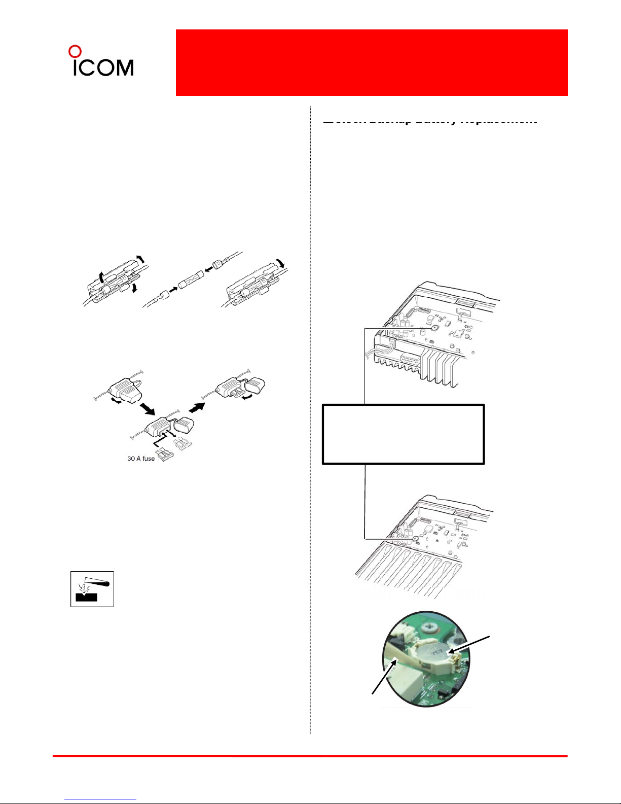
3-8 Maintenance
■
Fuse Replacement
Fuses should be installed in the fuse holder of the
black and red power cables, respectively. If a fuse
blows or the transceiver stops functioning, track
down the source of the problem if possible, and
replace the damaged fuse with a new one of the
same rating.
Clock Backup Battery Replacement
When the backup battery is discharged, the
transceiver transmits and receives normally but
cannot retain the current time.
1Remove the bottom cover to expose MAIN UNIT
(Refer to 3-7 Optional Internal Unit Installation)
2Replace the clock backup battery, located on the
Fuse rating: 20 A USE a 20 A fuse only.
for IC-F9511S, IC-F9511T
MAIN UNIT as below. (Make sure the battery
polarity is correct.)
3Recover the transceiver, and re-set the date and
time in set mode. (Refer to 4-1-8 Basic Operation,
Clock function.)
Fuse rating: 30 A USE a 30 A fuse only.
for IC-F9511HT
IC-F9511S/T
CLOCK BACKUP BATTERY
MAIN UNIT : “BT601”
Part No. : 3020000340
Part Name : ML-614S/ZT
■Cleaning
If the transceiver becomes dusty or dirty, wipe it
clean with a soft, dry cloth.
AVOID the use of solvents such as
benzene or alcohol, as they may
damage the transceiver surfaces.
IC-F9511HT
“+” side is UP
25
Remove old
battery using a
non-conductive flat
object
Battery removal
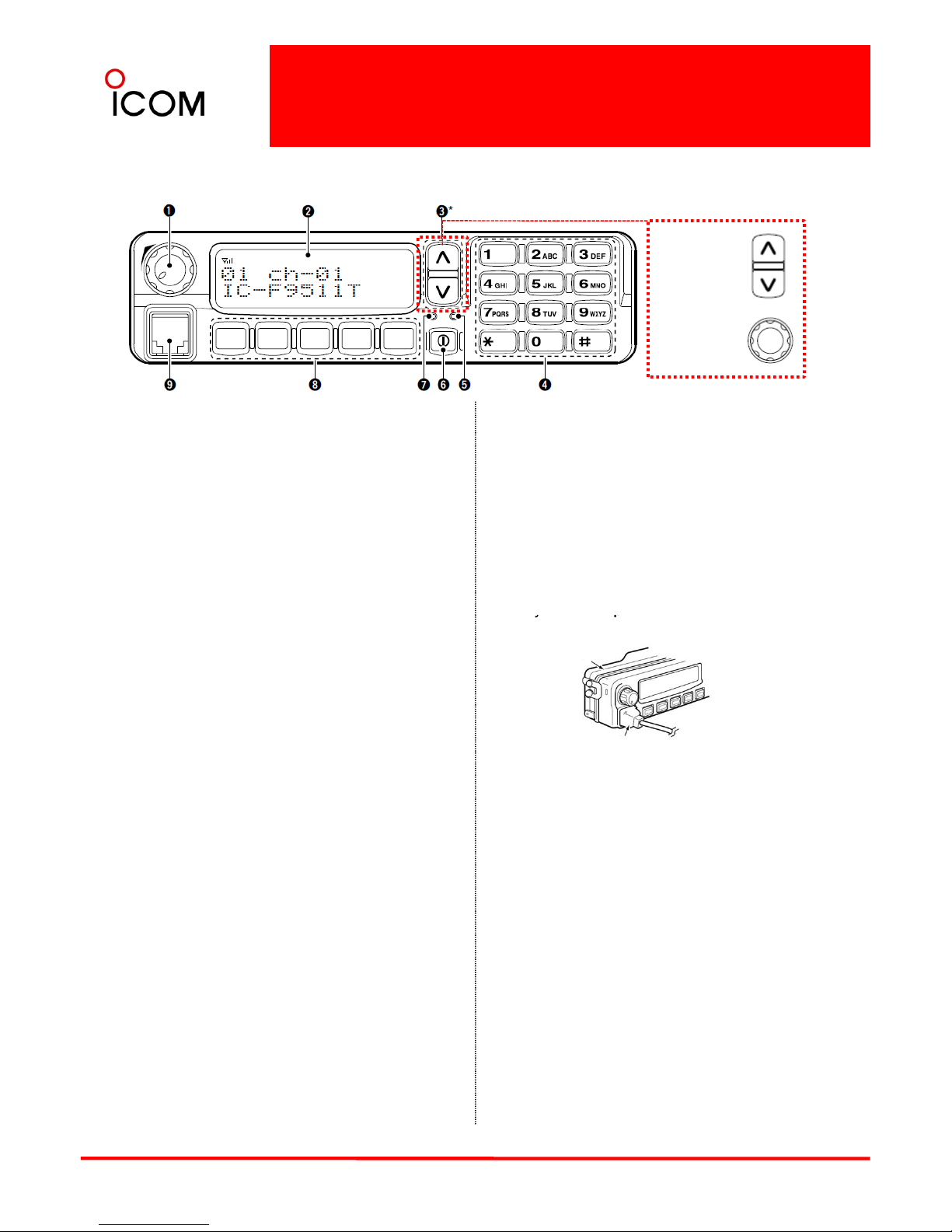
4-1 Operation and Function
4-1-1 Operation and Function
IC-F9511S, IC-F9511T
NOTE : Operation of the IC-F9521/F9523/S/T is also based on this instruction.
10 keypad
model
Up/Down Key
➊ AF VOLUME CONTROL KNOB
Rotate the knob to adjust the audio output level.
• Minimum audio level is pre-programmed.
➑DEALER-PROGRAMMABLE KEYS
Desired functions can be programmed independently
by your dealer. In this instruction manual, these keys
Simple model
Dial Key
➋FUNCTION DISPLAY
Displays a variety of information, such as an operating
channel number/name, DTMF numbers and audible
condition, etc.
➌UP/DOWN or DIAL KEYS
• 10-key model: UP/DOWN Keys
are from the left, called [P0]/[P1]/[P2]/[P3]/[P4]
.
➒MICROPHONE CONNECTOR
Connect the supplied or optional microphone.
• When you connect a microphone, be sure to fit the
connector cover of the microphone into the
connector to maintain the front panel’s dust
protection and splash resistance*.
*Onl
y
when the optional RMK-2 is attached.
Push to select an operating channel, etc.
• Simple model: DIAL
Rotate to select an operating channel, etc.
*The desired function can be assigned by your
dealer.
➍10-KEYPAD (10-key model only)
The keypad allows you to enter digits to:
yp
RMK-2
Connector cover
• Select memory channels, tone channels an
d DTMF
codes (when in the DTMF code channel selection
mode)
• Start up with a password
• Input the Individual ID code for digital operation.
(Depending on the pre-set value)
➎BUSY INDICATOR
NEVER connect non-specified microphones.
The pin assignments may be different and the
transceiver may be damaged.
MICROPHONE
The supplied microphone has a PTT switch and a
hanger hook.
Lights green while receiving a signal, or when the
squelch is open.
➏POWER SWITCH [POWER]
Push to turn the power ON and OFF.
• The following functions are available at power ON as
options:
➣ Automatic scan start
• The following functions are available when the
microphone is on or off hook (depending on the
setting):
➣ Automatic scan starts when it is on hook.
➣ Scan is cancelled when it is off hook.
➣ Scan is paused when it is off hook.
➣ Automatic priority channel selection is available
when it is off hook.
26
➣
Password prompt
➣ Set mode
➐TRANSMIT INDICATOR
Lights red while transmitting.
* P25 operation only
➣ Sets to ‘Inaudible’ condition (mute condition)
when it is on hook.
➣ Sets to ‘Audible’ condition (unmute condition)
when it is off hook.
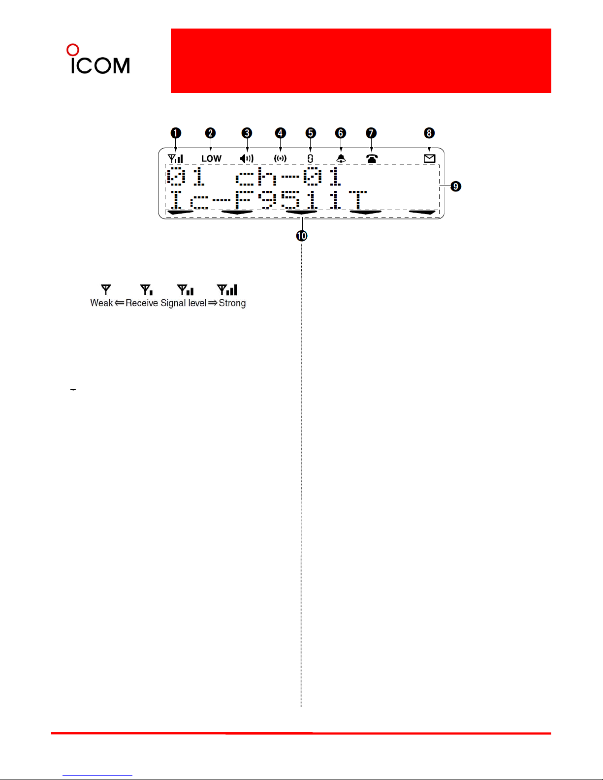
4-1-2 Function Display
IC-F9511S/T,F9521S/T, F9523S/T
➊RECEIVED SIGNAL STRENGTH INDICATOR
Indicates relative signal strength level.
➒ALPHANUMERIC DISPLAY
Displays an operating channel number, channel
name, Set mode contents, DTMF code, etc.
➋LOW POWER INDICATOR
Appears when low output power is selected.
* When high output power is selected, no indicator
appears.
➌
AUDIBLE INDICATOR
➓ACTIVATED KEY INDICATOR
Appears above the key assigned as [Scan Add/Del
(Tag)] key when that key has been activated.
See the operating guide for details of Analog
and P25 Trunking/Conventional system
operations. Consult your Icom dealer or system
➌
Appears when the channel is in the ‘audible’
(unmute) condition.
➍COMPANDER INDICATOR
Appears when the compander function* is activated.
* Analog mode operation only
operator for details concerning your
transceiver’s programming.
➎
SCRAMBLER INDICATOR
Appears when the voice scrambler or encryption
function is activated.
➏BELL INDICATOR
Appears/blinks when the specific page call* is
received, depending on how the transceiver has been
pre-programmed.
* P25
operation only
➐TELEPHONE INDICATOR
Appears when a phone call* is received.
* P25 operation only
➑SHORT MESSAGE INDICATOR
Appears when a Status message or Short message is
27
received.
* P25 operation only
 Loading...