

Page 1

OPERATING GUIDE
FOR IC-F9010/IC-F9020/
IC-F9510/IC-F9520 SERIES
ANALOG/MDC 1200 SYSTEM
/
APCO P25 MODE OPERATIONS
Page 2

IMPORTANT
Thank you for purchasing this Icom transceiver.
The Analog/MDC 1200 system/APCO P25 system functions
are usable for your transceiver.
READ ALL INSTRUCTIONS OF THE SYSTEM
carefully and completely before using the transceiver.
INFORMATION:
✔
In this operating guide, the following descriptions are used;
• “Non-display types” : Models ending in “B”
• “Simple types” : Models ending in “S”
• “10-key types” : Models ending in “T” (including “HT”)
SAVE THIS OPERATING GUIDE — This operating
guide contains important oper ating instructions for,
• IC-F9011B/S/T
• IC-F9021B/S/T, IC-F9023B/S/T u h f p25 t r u n k i n g h a n d h e l d
t r a n s c e i v e r s
• IC-F9511S/T/HT v h f p25 t r u n k i n g m o b i l e t r a n s c e i v e r s
• IC-F9521S/T, IC-F9523S/T u h f p25 t r u n k i n g m o b i l e t r a n s -
c e i v e r s
Icom, Icom Inc. and the Icom logo are registered trademarks of Icom Incor-
porated (Japan) in Japan, the United States, the United Kingdom, Germany,
France, Spain, Russia and/or other countries.
All other products or brands are registered trademarks or trademarks of their
respective holders.
i
v h f p25 t r u n k i n g h a n d h e l d t r a n s c e i v e r s
Page 3

TABLE OF CONTENTS
IMPORTANT .......................................................................... i
TABLE OF CONTENTS ........................................................ ii
1 PREPARATION..........................................................1–10
n Programmable key functions ........................................ 1
2 ANALOG MODE OPERATION ................................11–14
n Tone Signaling ............................................................11
n TX Code CH Selection ............................................... 11
n DTMF transmission .................................................... 12
n Scrambler function .....................................................12
n Emergency transmission ............................................13
n Man Down Emergency Call
(Handheld transceivers only) .....................................14
3 MDC 1200 SYSTEM OPERATION ..........................15–24
n MDC 1200 system operation ...................................... 15
n Receiving a call .......................................................... 15
n Transmitting a call ....................................................... 19
n Man Down Emergency Call
(Handheld transceivers only) .....................................24
n Status message transmission ....................................24
4 APCO P25 MODE OPERATION .............................25–57
n General.......................................................................25
n Control Channel Hunt function
(P25 Trunking mode only) ..........................................26
n Roaming function (P25 Trunking mode only) .............28
n Site Lock function (P25 Trunking mode only) .............28
n Site Select function (P25 Trunking mode only) ........... 29
n Individual call .............................................................. 29
n Talkgroup call..............................................................31
n Pager function ............................................................ 33
n Radio Inhibit function .................................................. 35
n Radio Uninhibit function .............................................37
n Remote Monitor function ............................................ 39
n Radio Check function ................................................. 41
n Status Message .........................................................43
n Short Message ........................................................... 45
n Status Query function ................................................. 47
n Phone call ..................................................................49
n Announcement function ............................................51
n Emergency transmission ............................................52
n Man Down Emergency Call
(Handheld transceivers only) .....................................54
n Talk Back function .......................................................55
n Encryption function ..................................................... 56
5 TACTICAL GROUP FUNCTION ..............................58–62
n Tactical Group function ...............................................58
1
2
3
4
5
6
7
8
9
10
11
12
13
14
15
16
ii
Page 4

1
PREPARATION
n Programmable key functions
The programmable key functions can be assigned to the following keys and switches;
Handheld transceivers:
[EMR], [Side1], [Side2], [Side3], [I]*
1
[∫]*
, [√]*1, [APP]*1, [HOME]*1, ABC switch and Toggle
switch.
1
*
Available on Simple and 10-key types only
Mobile transceivers:
2
[UP]*
, [DOWN]*2, [P0], [P1], [P2], [P3] and [P4].
2
*
Available on 10-key types only
Consult your Icom dealer or system operator for details concerning your transceiver’s programming.
1
, [II]*1, [III]*1, [Ω]*1, [≈]*1,
For Handheld transceivers:
❍ ABC and Toggle switches
The programmable key functions for the ABC and Toggle
switches are limited. (See p. 10 for details.)
❍ Key indicator (Simple and 10-key types only)
If the key indicator shows the programmed function key
name, push the front panel key ([I], [II] or [III]) under the key
indicator to activate the programmed function.
( In the explanations that follow, the function key name for that
key indicator is displayed in double quotation marks; e.g.
“EMR.”)
❍ Non-display types
The programmable key functions are limited, and some key
functions operate differently between the Simple and 10-key
types.
1
Page 5
PREPARATION
1
D Programmable key functions availability
Programmable
key functions
CH Up, CH Down
CH Up/Down N/A
Zone
Zone Up/Down N/A
Scan A, Scan B
Scan Add/Del(Tag)
Prio A, Prio B
Prio A (Rewrite),
Prio B (Rewrite)
MR-CH 1, 2, 3, 4
Moni
Public Address N/A
RX Speaker N/A
Light
Lock
Talk Around
Analog APCO P25
HH MB HH MB
2
*
✔
✔
✔
✔
✔
✔
✔ ✔
✔
2
*
✔ ✔
✔
1
*
✔ ✔
2
*
✔ ✔
✔ ✔ ✔ ✔
1
*
✔ ✔
✔ ✔ ✔ ✔
✔ ✔ ✔ ✔
✔
✔
✔ ✔ ✔ ✔
✔ ✔ ✔ ✔
1
*
✔ ✔
N/A
N/A
N/A
N/A
2
*
2
*
1
*
2
*
1
*
1
*
REF.
✔
✔
✔
✔
✔
✔
✔
✔
✔
✔
IM
IM
IM
IM
IM
IM
IM
IM
IM
IM
IM
IM
IM
IM
IM
Programmable
key functions
High/Low
Surveillance*
Hook Scan N/A
OPT1 Out, OPT2 Out,
OPT3 Out
OPT1 Momentary,
OPT2 Momentary,
OPT3 Momentary
User Set Mode
Clock
Menu <, Menu >
Re-dial
DTMF Autodial
Compander
Scrambler
Emergency
Lone Worker*
3
3
HH MB HH MB
✔
✔ ✔ ✔ ✔
✔
✔ ✔ ✔ ✔
✔
✔
✔
✔ ✔
✔
✔
✔
✔ ✔ ✔ ✔
✔ ✔ ✔ ✔
Analog APCO P25
1
*
✔ ✔
✔
1
*
✔ ✔
2
*
✔ ✔
2
*
✔ ✔
2
N/A
*
1
*
✔
1
*
✔
1
*
✔
1
*
✔
N/A
✔
N/A N/A p. 4
N/A N/A p. 4
N/A N/A pp. 4, 10
N/A N/A pp. 4, 10
✔
1
*
✔
2
*
✔
2
*
✔
*2N/A IM
☞ Continued on the next page
REF.
IM
IM
IM
IM
IM
IM
IM
p. 5
p. 5
1
2
3
4
5
6
7
8
9
10
11
12
13
14
15
16
HH: Handheld MB: Mobile
IM: Instruction Manual N/A: Not Applicable
*1 Simple/10-key and Non-display types operate differently.
*2 Not available on Non-display types.
*3 With revision 1.7 or later transceivers, Simple/10-key and Non-
display types operate differently.
2
Page 6
PREPARATION
1
D Programmable functions availability (Continued)
Programmable
key functions
Home
Ext.CH Sel Mode N/A
Scrambler/Encryption
Zeroize N/A N/A
Site Lock N/A N/A
Encryption N/A N/A
Digital Button N/A N/A
Digital Status N/A N/A
Dgital Page N/A N/A
Digital Message N/A N/A
Phone N/A N/A
Site Select N/A N/A
Individual N/A N/A
Talkgroup N/A N/A
Rekey N/A N/A
Keyset N/A N/A
Analog APCO P25
HH MB HH MB
✔ ✔ ✔ ✔
N/A
✔
1
*
✔
✔ ✔
1
*
✔ ✔
✔ ✔
1
*
✔
2
*
✔
2
*
✔
2
*
✔
2
*
✔
2
*
✔
2
*
✔
2
*
✔
2
*
✔
2
*
✔
2
*
✔
✔
✔
✔
✔
✔
✔
✔
✔
✔
✔
✔
✔
✔
REF.
pp. 5, 6
p. 6
pp. 6, 10
p. 7
pp. 7, 10
pp. 7, 10
p. 8
p. 8
p. 8
p. 8
p. 8
p. 9
p. 9
p. 9
p. 9
p. 9
With revision 1.7 or later transceivers, the following keys are additionally programmable.
Programmable
key functions
Scan
C.Tone CH Ent
Call, Call A, Call B
TX Code CH Select
TX Code CH UP,
TX Code CH DN
MDC Call
MDC SelCall
MDC CallAlert
Tone/NAC CH Select
Analog APCO P25
HH MB HH MB
1
*
✔
2
*
✔
✔ ✔
2
*
✔
2
*
✔
2
*
✔
2
*
✔
2
*
✔
2
*
✔
✔ ✔
✔
✔
✔
✔
✔
✔
✔ ✔
1
*
N/A N/A p. 4
N/A N/A p. 4
N/A N/A p. 4
N/A N/A p. 4
N/A N/A p. 5
N/A N/A p. 5
N/A N/A p. 5
2
*
REF.
✔
✔
IM
p. 7
[Scan] is programmable instead of [Scan A] and [Scan B].
HH: Handheld MB: Mobile
IM: Instruction Manual N/A: Not Applicable
1
*
Simple/10-key and Non-display types operate differently.
*2
Not available on Non-display types.
3
Page 7

PREPARATION
1
D Analog mode operation
(Common operation)
RE-DIAL KEY “DTMR”
Push to transmit the last-transmitted DTMF code.
(Simple/10-key and Non-display types operate differently)
DTMF AUTODIAL KEY “DTMA” (p. 12)
❍ For Simple and 10-key types
➥ Push to enter the DTMF channel selection mode, then
select a desired channel using [CH Up]/[CH Down] or [CH
Up/Down].
➥ After selecting the channel, push to transmit the DTMF
code.
❍ For Non-display types
➥ Push to transmit the DTMF code programmed in DTMF
channel 1.
COMPANDER KEY “COMP”
❍ For Simple and 10-key types
Push to turn the Compander function ON or OFF.
This function reduces noise components from the transmitted audio to provide clear communication.
❍ For Non-display types
➥
Push and hold for 1 sec. to turn the Compander function ON.
➥ If the function is ON, push to turn it OFF.
SCRAMBLER KEY “SCR” (p. 12)
❍ For Simple and 10-key types
Push to turn the Voice Scrambler function ON or OFF.
❍ For Non-display types
➥ Push and hold for 1 sec. to turn the Voice Scrambler func-
tion ON.
➥ If the function is ON, push to turn it OFF.
The following functions are programmable for only transceivers whose revision number is 1.7 or later.
(Not available on Non-display types)
CALL KEYS “CALL” “CALA” “CALB” (p. 11)
Push to transmit a 2-tone code.
• Call transmission is necessary before you call another station, depending on your signaling system.
• [Call A] and/or [Call B] may be available when your system em-
ploys selective ‘Individual/Group’ calls. Ask your dealer which call is
assigned to each key.
TX CODE CHANNEL SELECT KEY “TXC” (p. 11)
Push to enter the ID code channel selection mode, and then
select a desired channel using
Up/Down].
TX CODE CHANNEL UP/DOWN KEYS “TXCU” “TXCD” (p. 11)
Push to select a TX code channel directly.
C.TONE CH ENT KEY “T SEL”
Push to enter the continuous tone channel selection mode,
and then select a desired tone frequency/code setting using
[CH Up]/[CH Down] or [CH Up/Down]. The selected channel remains set as the continuous tone channel until another
channel is designated as such.
[CH Up]/[CH Down] or [CH
1
2
3
4
5
6
7
8
9
10
11
12
13
14
15
16
4
Page 8

PREPARATION
1
D MDC 1200 system operation
The following functions are programmable for only transceivers whose revision number is 1.7 or later.
(Not available on Non-display types)
MDC CALL KEY “MDC”
➥ Push to enter the MDC menu selection mode, then select
a desired MDC menu from “SELCALL,” “CALALERT,”
“STUN,” “REVIVE,” “RADIOCHK,” “STATUS,” “MSG,” “STAT
POL,” and “CALL LOG” using [CH Up]/[CH Down] or [CH
D Analog and APCO P25 modes operation
(Common operation)
EMERGENCY KEY “EMR” (pp. 13, 23, 52)
Push and hold for the specified time period*, to enter the
emergency mode. After the specified time period* has passed,
an Emergency call or alarm is transmitted once, or repeat-
edly*.
• To exit the emergency mode, push and hold for the specied time period* again before transmitting.
* Depending on the pre-setting. Ask your dealer for details.
Up/Down].
After selecting, push this key again to enter the transceiv-
er alias selection mode.
• If no operation is performed for about 15 sec., the transceiver
returns to the normal operating mode.
➥ While in the transceiver alias selection mode, push to
return to the MDC menu selection mode.
MDC SELCALL KEY “SELC” (p. 19)
Push to enter the transceiver alias selection mode for SelCall.
• After the desired alias selection, push [PTT] to transmit a SelCall.
• If no operation is performed for about 15 sec., the transceiver
returns to the normal operating mode.
MDC CALLALERT KEY “CALA” (p. 19)
Push to enter th e transce iver a lias selecti on mode for
CallAlert.
• After the desired alias selection, push [PTT] to transmit a CallAlert.
• If no operation is performed for about 15
returns to the
normal operating mode.
sec.
, the transceiver
LONE WORKER KEY “LONE”
Push to turn the Lone Worker function ON or OFF.
• If the Lone Worker function is activated, the Emergency function is
automatically turned ON after the specied time period* has passed
with no operation performed.
* Depending on the pre-setting. Ask your dealer for details.
With Non-display types whose revision number is 1.7 or
later, push and hold this key for 1 sec. to turn the Lone
Worker function ON. If the function is ON, push to turn it
OFF.
HOME KEY “HOME”
➥ Push to return to the normal operating mode from each
selected mode, such as Individual ID, Talkgroup ID, DTMF
code channel, and so on.
➥ When the Full Off Air Call SetUp (FOACSU) function is
turned ON on the Trunking mode, push to ignore the re-
ceiving call. (p. 30)
5
Page 9
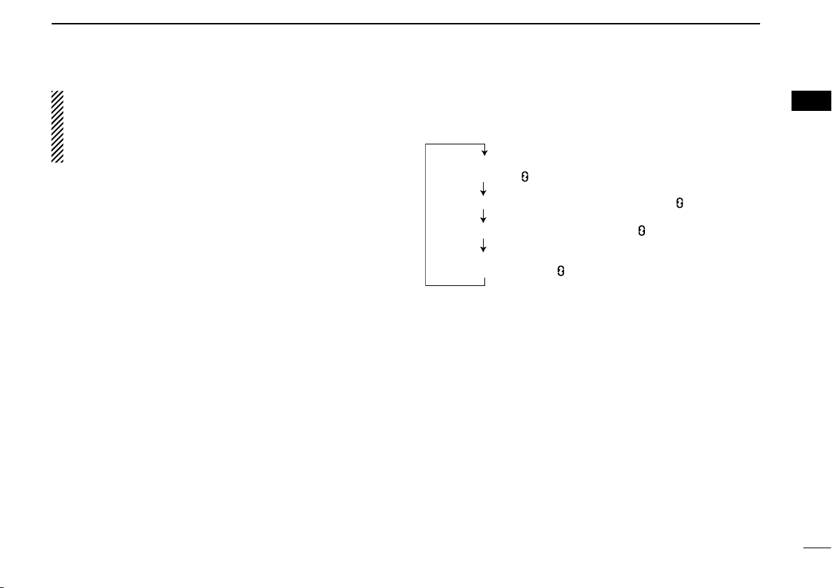
Voice Scrambler function ON (“SCRM” appears* / “ ” appears)
Voice Scrambler and Encryption functions ON
(“SCRM/ENC” appears* / “ ” appears)
Voice Scrambler and Encryption functions OFF
(“OFF” appears* / “ ” disappears)
Encryption function ON (“ENC” appears* / “ ” appears)
PUSH
PUSH
PUSH
PUSH
* Appears for about 1 sec.
PREPARATION
1
[Home] has the following additional functions with transceivers whose revision number is 1.7 or later
➥ While in the emergency mode, push to exit the mode.
➥
While in the APCO P25 mode, push to cancel the talk
back function.
Ext. CH Sel Mode KEY (Available on Mobile transceivers only)
Push to turn the Memory Channel Select function from an ex-
ternal input ON or OFF.
When this function is turned ON, and a signal is input from an
external unit that is connected to the D-sub 25-pin connector,
the operating channel changes to the desired memory channel. In that case, a memory channel selection with the key or
dial operation, and the microphone hanger action functions,
Move to Priority A Channel and On Hook Scan, are disabled.
When this function is turned OFF, the memory channel selec-
tion from an external input is disabled.
• This function is usable when an external unit is connected to the
transceiver.
• Ask your dealer for details of an external input.
(Simple/10-key and Non-display types operate differently)
SCRAMBLER/ENCRYPTION KEY “S/D”
- The UT-125 a e s /d e s e n c r y p t i o n u n i t or UT-128 d e s e n c r y p t i o n
u n i t is required for the Encryption function.
❍ For Simple and 10-key types
➥ While in the analog mode, push to turn the Voice Scrambler
function ON or OFF.
➥ While in the APCO P25 mode, push to turn the Encryption
function ON or OFF.
➥ While in the mixed (digital and analog) mode, push to turn
:
the Voice Scrambler and Encryption functions ON or OFF,
separately or simultaneously, as shown below.
1
2
3
4
5
6
7
8
9
10
❍ For Non-display types
➥ While in the analog mode, push and hold for 1 sec. to turn
the Voice Scrambler function ON. If the function is ON,
push to turn it OFF.
➥ While in the APCO P25 mode, push and hold for 1 sec.
to turn the Encryption function ON. If the function is ON,
push to turn it OFF.
➥
While in the mixed (digital and analog) mode, push and hold
for 1 sec. to turn both the Voice Scrambler and Encryption
functions ON. If the functions are ON, push to turn them
OFF.
☞ Continued on the next page
11
12
13
14
15
16
6
Page 10

PREPARATION
1
D Analog and APCO P25 modes operation (Continued)
(Not available on Non-display types)
TONE/NAC CH SELECT KEY “T SEL”
➥ While in the analog mode, push to enter the continuous
tone channel selection mode, then select a desired tone
frequency/code setting using [CH Up]/[CH Down] or [CH
Up/Down]. After selecting, push this key again to set.
➥ While in the APCO P25 mode, push to enter the NAC
channel selection mode, then select a desired NAC setting using [CH Up]/[CH Down] or [CH Up/Down]. After
selecting, push this key again to set.
➥ While in the mixed (digital and analog) mode, push to enter
the continuous tone channel selection mode, then select
a desired tone frequency/code setting using [CH Up]/[CH
Down] or [CH Up/Down]. After selecting, push this key to
set. After that, the NAC channel selection screen appears.
Select a desired NAC setting using [CH Up]/[CH Down]
or [CH Up/Down]. After selecting, push this key again to
set.
D APCO P25 mode operation
(Common operation)
ZEROIZE KEY “ZERO”
Push and hold for 1 sec. to zeroize the encryption key data
which is programmed by the key loader.
After zeroising, the transceiver cannot decrypt the encrypted
code.
SITE LOCK KEY “SLCK” (Trunking mode only) (p. 28)
Push to lock the transceiver to the current registered site.
When the Site Lock function is activated, roaming and the
background scan are inhibited.
Push again to turn the Site Lock function OFF.
(Simple/10-key and Non-display types operate differently)
ENCRYPTION KEY “DENC” (p. 56)
- The UT-125 a e s /d e s e n c r y p t i o n u n i t or UT-128 d e s e n c r y p t i o n
u n i t is required.
❍ For Simple and 10-key types
Push to turn the Encryption function ON or OFF.
❍ For Non-display types
➥ Push and hold for 1 sec. to turn the Encryption function
ON.
➥ If the function is ON, push the key to turn it OFF.
7
Page 11

PREPARATION
1
(Not available on Non-display types)
DIGITAL BUTTON KEY “DSEL”
➥ Push to enter the digital call type selection mode, then
push [CH Up]/[CH Down] or rotate [CH Up/Down] to
select a desired call type from “PAGE,” “RDO INHIBIT,”
“RDO UINHIBIT,” “RDO MONITOR,” “ RDO CHECK,”
“STATUS,” “SHORT MSG,” “STATUS QUERY,” “PHONE”
and “ANNOUNCEMENT.” (p. 25)
After making the digital call type selection, push this key
again to enter the ID selection mode.
• If “STATUS” or “SHORT MSG” is selected, the transceiver dis-
plays the Status Message or Short Message selection mode
before entering the Individual ID selection mode.
• If “PHONE” is selected, the transceiver displays the phone
number selection mode.
• If no operation is performed for about 30 sec., the transceiver
returns to normal operation.
➥ Push and hold for 1 sec. to cancel and return to normal
operation.
DIGITAL STATUS KEY “STAT” (p. 43)
➥ Push to enter the Status Message selection mode.
After sel ect ing , push again to enter the destination
Individual ID selection mode to send a Status Message.
• If no operation is performed for about 30 sec., the transceiver
returns to normal operation.
• While in the Trunking mode, the Individual ID selection mode
does not appear.
➥ Push and hold for 1 sec. to cancel and return to normal
operation.
DIGITAL PAGE KEY “PAGE” (p. 33)
➥ Push to enter the Individual ID selection mode for a Page
call. Then push [CH Up]/[CH Down] or rotate [CH Up/
Down] to select a desired Individual ID.
• Push [PTT] to transmit a Page call.
• If no operation is performed for about 30 sec., the transceiver
returns to normal operation.
➥ Push and hold for 1 sec. to cancel and return to normal
operation.
DIGITAL MESSAGE KEY “MSG” (p. 45)
➥
Push to enter the Short Message selection mode.
After selecting, push again to enter the destination
Individual ID selection mode to send a Short Message.
• If no operation is performed for about 30 sec., the transceiver
returns to normal operation.
• While in the Trunking mode, the Individual ID selection mode
does not appear.
➥ Push and hold for 1 sec. to cancel and return to normal
operation.
PHONE KEY “PHON” (p. 49)
➥ Push to enter the phone number selection mode for a
Phone call. Then push [CH Up]/[CH Down] or rotate [CH
Up/Down] to select a desired phone number.
• Push [PTT] to transmit the Phone call.
• If no operation is performed for about 30 sec., the transceiver
returns to normal operation.
➥ Push and hold for 1 sec. to cancel and return to normal
operation.
☞ Continued on the next page
1
2
3
4
5
6
7
8
9
10
11
12
13
14
15
16
8
Page 12

9
1
PREPARATION
D APCO P25 modes operation (Continued)
SITE SELECT KEY “SSEL” (Trunking mode only) (p. 29)
Push to select “SITE 1,” then push again to display the site
information (RFSS ID and SITE ID), and you can edit the
RFSS and SITE IDs. Push and hold [Site Select] for 1 sec.
to set and return to normal operation.
INDIVIDUAL KEY “INDV” (p. 29)
Push to directly enter the Individual ID selection mode,
then select a desired Individual ID code using [CH Up]/[CH
Down] or [CH Up/Down].
• The Individual ID can be edited with the 10-keypad*. (Depending
on the pre-setting.)
*10-key types only.
• While in the Individual ID selection mode, push to cancel and
return to normal operation.
TALKGROUP KEY “TGID” (p. 31)
Push to directly enter the Talkgroup ID selection mode,
then select a desired Talkgroup ID code using [CH Up]/[CH
Down] or [CH Up/Down].
• While in the Talkgroup ID selection mode, push to cancel and
return to normal operation.
KEYSET “KSET” (OTAR mode only) (p. 57)
➥ Push to enter the keyset selection mode, then select a
desired keyset using [CH Up]/[CH Down] or [CH Up/
Down].
➥ During the keyset selection mode, push and hold this key
for 1 sec. to set the selected keyset, and push again to exit
the keyset selection mode.
REKEY “REKY” (OTAR mode only) (p. 57)
Push and hold for 1 sec. to transmit a Key Management
Message (KMM-Hello command) to a Key Management
Facility (KMF) to request rekeying.
Page 13

10
1
1
PREPARATION
D For ABC and Toggle switches only
SCRAMBLER SWITCH (Analog mode only)
Turns the Voice Scrambler function ON or OFF.
COMPANDER SWITCH (Analog mode only)
Turns the Compander function ON or OFF.
The Compander function reduces noise components from
the transmitted audio to provide clear communication.
SCRAMBLER/ENCRYPTION SWITCH
(Analog and APCO P25 modes)
- The UT-125 a e s /d e s e n c r y p t i o n u n i t or UT-128 d e s e n c r y p t i o n
u n i t is required for the Encryption function.
➥ While in the analog mode, turns the Voice Scrambler
function ON or OFF.
➥ While in the P25 Conventional mode, turns the Encryption
function ON or OFF.
➥ While in the mixed (digital and analog) mode, simultane-
ously turns the Voice Scrambler and Encryption functions
ON or OFF.
ENCRYPTION SWITCH (APCO P25 mode only)
- The UT-125 a e s /d e s e n c r y p t i o n u n i t or UT-128 d e s e n c r y p t i o n
u n i t is required.
Turns the Encryption function ON or OFF.
SITE LOCK SWITCH (APCO P25 Trunking mode only)
Locks the transceiver in the currently registered site.
When the Site Lock function is activated, roaming and the
background scan are inhibited.
2
3
4
5
6
7
8
9
10
11
12
13
14
15
16
Page 14
Selective calling
Non-selective calling
2
ANALOG MODE OPERATION
n Tone Signaling*
When your system employs tone signaling (excluding CTCSS
and DTCS), this call procedure may be necessary prior to
voice transmission. The tone signaling employed may be a
selective calling system, which allows you to call specic
station(s) only and prevent unwanted stations from contact-
ing you.
q Select the desired TX code channel according to your sys-
tem operator’s instructions. (Only
• This may not be necessary, depending on programming.
• Refer to the right column for the selecting procedure.
w Push [Call] (assigned to one of the dealer programmable
keys).
e After transmitting, the remainder of your communication
can be carried out in the normal fashion.
Simple and 10-key types)
n TX Code CH Selection*
If the transceiver has [TX Code CH Select] assigned to it,
the indication can be toggled between the operating channel
number (or name) and TX code channel number (or name).
When the TX code channel number (or name) is displayed,
[CH Up], [CH Down] or [CH Up/Down] selects a TX code
channel.
Not available on Non-display types.
USING [TX CODE CH SELECT] :
q Push [TX Code CH Select]— a TX code channel number
(or name) appears.
w Push [CH Up] or [CH Down], or rotate [CH Up/Down] to
select a desired TX code channel.
e After selecting, push [TX Code CH Select] to set.
• Return to the stand-by mode.
r Push [Call] to transmit the selected TX code.
USING [TX CODE CH UP]/[TX CODE CH DOWN]:
If the transceiver has a [TX Code CH Up] or [TX Code CH
Down] key assignment, the programmed TX code channel
can be selected when pushed.
11
* These functions are usable with transceivers whose revision
number is 1.7 or later. Ask your dealer for details.
Page 15

ANALOG MODE OPERATION
2
n DTMF transmission
If the transceiver has [DTMF Autodial] assigned to it, the
automatic DTMF Transmission function can be used. Up to 8
DTMF channels are selectable.
q Push [DTMF Autodial]— a DTMF channel appears.
w Push [CH Up] or [CH Down], or rotate [CH Up/Down] to
select a desired DTMF channel.
e Push [DTMF Autodial] to transmit the DTMF code.
❍ For Non-display types
You cannot select a desired DTMF channel. Pushing [DTMF
Autodial] transmits the DTMF code programmed in DTMF
channel 1.
n Scrambler function
The Voice Scrambler function provides private voice communication between users.
q Push [Scrambler] or [Scrambler/Encryption] to turn the
Voice Scrambler function ON.
”
• “
w Push [Scrambler] or [Scrambler/Encryption] again to
• “
❍ For Non-display types
q Push and hold [Scrambler] or [Scrambler/Encryption]
w Push [Scrambler] or [Scrambler/Encryption] again to
(for Handhelds) or “ ” (for Mobiles) appears.
turn the function OFF.
”
(for Handhelds) or “ ” (for Mobiles) disappears.
for 1 sec. to turn the Voice Scrambler function ON.
turn the function OFF.
1
2
3
4
5
6
7
8
9
10
11
12
13
14
15
16
12
Page 16

13
ANALOG MODE OPERATION
2
n Emergency transmission
When [Emergency] is pushed and held for the specied time
1
period
*
, the DTMF emergency signal is transmitted once, or
repeatedly
1
*
, on the specied emergency channel.
A repeat emergency signal is automatically transmitted until
turning the transceiver OFF, or pushing [Home]
2
*
.
When no emergency channel is specied, the signal is transmitted on the previously selected channel.
If you want to cancel the emergency call, push and hold
[Emergency] again before transmitting the call.
If your transceiver is programmed for Silent operation, you
can transmit Emergency calls without the beep sounding or
the LCD display lighting.
IMPORTANT: It is recommended to set an emergency
channel individually to provide the certain emergency call
operation.
D NOTES
Depending on the pre-setting, the following functions are automatically activated. Ask your dealer for details.
• Auto TX function
The transceiver automatically transmits the microphone audio
for the specied time period
mission.
- The HM-148G or HM-152 h a n d m i c r o p h o n e is required for Mobile
transceivers.
• Auto RX function
The transceiver stands by in the audible mode for the speci-
ed time period
*1 Depending on the pre-setting. Ask your dealer for details.
*2 For only transceivers whose revision number is 1.7 or later.
1
*
, after the emergency call transmission.
1
*
after the emergency call trans-
13
Page 17

ANALOG MODE OPERATION
2
n Man Down Emergency Call
(Handheld transceivers only)
This function requires the optional UT-124R m a n d o w n u n i t .
When the transceiver has been left in a horizontal position for
the specied time period*, the transceiver enters the emergency mode, and then the countdown starts.
After the specied time period* has passed, an emergency
call is automatically transmitted once, or repeatedly*.
If the transceiver is placed in a vertical position before the
rst transmission, the transceiver exits the emergency mode
and the emergency call is canceled.
* Depending on the pre-setting. Ask your dealer for details.
1
2
3
4
5
6
7
8
9
10
11
12
13
14
15
16
14
Page 18
3
For Handhelds:
For Mobiles:
SE LCALL
SELCALL
MDC SELC CALA
ID 1234
ID 1234
MDC SELC CALA
MDC 1200 SYSTEM OPERATION
n MDC 1200 system operation
The MDC 1200 signaling system enhances your transceiver’s
capabilities. It allows PTT ID, Selective Calling (SelCall), Call
Alert, Radio Check, Stun, Revive, Status, Messaging and
Emergency signaling. This operation is usable with transceivers whose revision number is 1.7 or later.
An additional feature of MDC 1200 system found in Icom
transceivers is called aliasing. Each transceiver on the system
has a unique ID number. Aliasing allows the substitution of an
alphanumeric name for this ID number. For transmit, you can
use this alias to select a transceiver to call. For receive, the
alias of the calling station is displayed instead of the ID.
Please note that your dealer has set one of the programma-
15
ble keys for MDC 1200 system operation.
NOTE: During MDC 1200 system operation, APCO 25
system operation is not usable.
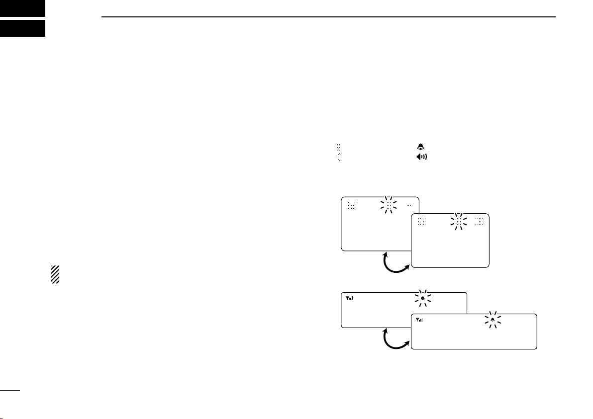
n Receiving a call
D Receiving a SelCall
q When a SelCall is received;
• Beeps sound.
• The LED indicator (for Handhelds) or Busy indicator (for Mo-
biles) lights green, or blinks orange (for Non-display types).
”
• “
• “ ” (for Handhelds) or “ ” (for Mobiles) appears*.
• The calling station ID (or alias) and “SELCALL” are displayed
w Push and hold [PTT] and speak into the microphone.
e Release [PTT] to receive a response.
* Simple and 10-key types only.
(for Handhelds) or “ ” (for Mobiles) blinks*.
alternately*.
Page 19
MDC 1200 SYSTEM OPERATION
For Handhelds:
For Mobiles:
CA LLALR
CALLALRT
MDC SELC CALA
ID 1234
T
ID 1234
MDC SELC CALA
For Handhelds:
For Mobiles:
EM GL EMG
EMG EMG
MDC SELC CALA
ID 1234
T
ID 1234
MDC SELC CALA
3
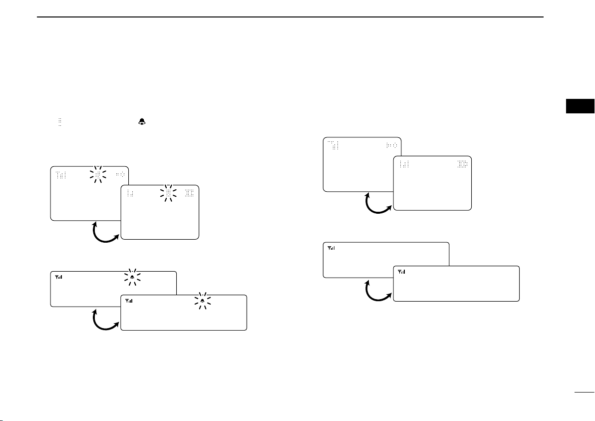
D Receiving a Call Alert
q When a Call Alert is received;
• Beeps sound.
• The LED indicator (for Handhelds) or Busy indicator (for Mobiles)
lights green, or blinks orange (for Non-display types).
”
• “
• The calling station ID (or alias) and “CALLALRT” are displayed
alternately*.
w Push and hold [PTT] and speak into the microphone.
e Release [PTT] to receive a response.
(for Handhelds) or “ ” (for Mobiles) blinks*.
D Receiving an Emergency Call
q When an emergency call is received;
• Beeps sound.
• The calling station ID (or alias) and “EMG EMG” are displayed
alternately until turning power OFF, the channel changing, etc*.
w When the automatic acknowledgement function is turned
ON, the transceiver automatically transmits an acknowledgement call to the calling station.
e Turn power OFF, change the channel, etc. to stop the
beeps and display indication.
1
2
3
4
5
6
7
8
9
10
11
12
13
14
15
16
* Simple and 10-key types only.
16
Page 20
17
MDC 1200 SYSTEM OPERATION
For Handhelds:
For Mobiles:
MS GL 1 MG
MSG 1
MDC SELC CALA
ID 1234
T
ID 1234
MDC SELC CALA
For Handhelds:
For Mobiles:
ST ATUS1
STATUS1
MDC SELC CALA
ID 1234
T
ID 1234
MDC SELC CALA
3
D Receiving a Message
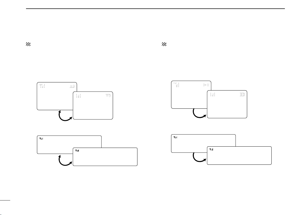
Not available on Non-display types.
q When a Message is received;
• Beeps sound.
• The calling station ID (or alias) and the message are displayed
w Turn power OFF, push [PTT], change the channel, etc. to
stop the display indication.
alternately.
D Receiving a Status Message
Not available on Non-display types.
➥ When a Status Message is received;
• Beeps sound.
• The calling station ID (or alias) and the status message are dis-
played once.
Page 21

18
3
MDC 1200 SYSTEM OPERATION
Calling station ID
ID 1234
SC - 0:27
MDC SELC CALA
ID 12343
SCT - UNK 0:27
Elapsed time from
receiving the call
: SelCall
: Call Alert
: Emergency call
Call type
SC
CA
EMG
3
D Receiving a Stun or Revive
If a Stun command is received that matches your station ID,
the transceiver will display “SORRY” (
only) and you can not receive or transmit. When a Revive
command is received that matches your station ID, normal
operation is restored.
D Receiving a Radio Check or Status Polling
If a Radio Check or Status polling command that matches
your station ID, the transceiver will transmit automatically.
➥ When a Radio Check command is received;
• The transceiver automatically transmits the acknowledgement
call.
➥ When a Status Polling command is received;
• The transceiver automatically transmits the status call. (Simple
and 10-key types only)
D Call log function
Not available on Non-display types.
After receiving a SelCall, Call Alert or Emergency call, the
call log is displayed (depends on the setting.) Up to 5 logs
can be memorized, and the oldest log is erased when the 6th
call is received.
q Push [MDC CALL] to enter the MDC menu selection mode.
w Push [CH Up] or [CH Down], or rotate [CH Up/Down] to
select “CALL LOG.”
Simple and 10-key types
e Push [MDC] again to display a call log.
• When no call is received, an error beep sounds.
For Handhelds: For Mobiles:
r Push [CH Up] or [CH Down] to select a desired one.
NOTE: If 1000 hours has passed after receiving the call,
the elapsed time will be reset to 0:00.
1
2
4
5
6
7
8
9
10
11
12
13
14
15
16
Page 22

19
SELCALL T
INDIVIDUAL1
SELCALL−UP
INDIVIDUAL1
MDC SELC CALA
CALALERT
INDIVIDUAL1
CALALERT−UP
INDIVIDUAL1
MDC SELC CALA
MDC 1200 SYSTEM OPERATION
3
n Transmitting a call
D Transmitting a SelCall
SelCall allows you to make a call to a specic station or to a
particular group. Other MDC 1200 system transceivers on the
channel will not receive a SelCall that does not match their
station or group ID’s.
Not available on Non-display types.
q Push [MDC Call] to enter the MDC menu selection mode.
• Or push [MDC SelCall] to enter the transceiver alias selection
mode. In this case, skip step w.
For Handhelds: For Mobiles:
w Push [MDC Call] again to enter the transceiver alias se-
lection mode.
e Push [CH Up] or [CH Down], or rotate [CH Up/Down] to
select a desired alias.
r Push and hold [PTT] to transmit a SelCall to the selected
station, then speak into the microphone.
• “ ” (for Handhelds) or “ ” (for Mobiles) appears.
t Release [PTT] to receive.
D Transmitting a Call Alert
Call Alert allows you to notify another user who may be away
from the transceiver that you want to talk.
Not available on Non-display types.
q Push [MDC Call] to enter the MDC menu selection mode.
• Or push [MDC CallAlert] to enter the transceiver alias selection
mode. In this case, skip steps w and e.
w Push [CH Up] or [CH Down], or rotate [CH Up/Down] to
select “CALALERT.”
For Handhelds: For Mobiles:
e Push [MDC Call] again to enter the transceiver alias se-
lection mode.
r Push [CH Up] or [CH Down], or rotate [CH Up/Down] to
select a desired alias
t
Push [PTT] to transmit a Call Alert to the selected station.
• “CA CALL” is displayed.
y Release [PTT].
• “CA OK” is displayed after receiving an acknowledgement from
the targeted station.
• “CA FAIL” is displayed if the targeted station does not receive
the signal or send back an acknowledgement.
u After a specied time period has passed, the transceiver
will return to receive.
.
Page 23

20
3
STUNLERT
INDIVIDUAL1
STUN−UP
INDIVIDUAL1
MDC SELC CALA
REVIVERT
INDIVIDUAL1
REVIVE−UP
INDIVIDUAL1
MDC SELC CALA
MDC 1200 SYSTEM OPERATION
3
D Transmitting a Stun Call
Stun call allows you to send an MDC 1200 system signal that
will stun the targeted station.
Not available on Non-display types.
q Push [MDC Call] to enter the MDC menu selection mode.
w
Push [CH Up] or [CH Down], or rotate [CH Up/Down] to
select
For Handhelds: For Mobiles:
e Push [MDC Call] again to enter the transceiver alias se-
lection mode.
r Push [CH Up] or [CH Down], or rotate [CH Up/Down] to
select a desired alias
t Push [PTT] to transmit a stun call to the selected station.
• “STN TX” is displayed.
y Release [PTT].
• “STN ACK” is displayed after receiving an acknowledgement
from the targeted station.
• “STN FAIL” is displayed if the targeted station does not receive
the signal or send back an acknowledgement.
u After a specied time period has passed, the transceiver
will return to receive.
“STUN.”
.
D Transmitting a Revive Call
Revive call allows you to send an MDC 1200 system signal
that will revive the targeted (stunned) station.
Not available on Non-display types.
q Push [MDC Call] to enter the MDC menu selection mode.
w Push [CH Up] or [CH Down], or rotate [CH Up/Down] to
select “REVIVE.”
For Handhelds: For Mobiles:
e Push [MDC Call] again to enter the transceiver alias se-
lection mode.
r Push [CH Up] or [CH Down], or rotate [CH Up/Down] to
select a desired alias
t Push [PTT] to transmit a revive call to the selected sta-
tion.
• “REV TX” is displayed.
y Release [PTT].
• “REV ACK” is displayed after receiving an acknowledgement
from the targeted station.
• “REV FAIL” is displayed if the targeted station does not receive
the signal or send back an acknowledgement.
u After a specied time period has passed, the transceiver
will return to receive.
.
1
2
4
5
6
7
8
9
10
11
12
13
14
15
16
Page 24

21
RADIOCHK
INDIVIDUAL1
RADIOCHK−UP
INDIVIDUAL1
MDC SELC CALA
STATUSHK
INDIVIDUAL1
STATUS−UP
INDIVIDUAL1
MDC SELC CALA
MDC 1200 SYSTEM OPERATION
3
D Transmitting a Radio Check Call
Radio check call allows you to determine whether or not the
targeted station is turned on, within the communication range
and on channel, without requiring any action from the targeted station user.
Not available on Non-display types.
q Push [MDC Call] to enter the MDC menu selection mode.
w Push [CH Up] or [CH Down], or rotate [CH Up/Down] to
select “RADIOCHK.”
For Handhelds: For Mobiles:
e Push [MDC Call] again to enter the transceiver alias se-
lection mode.
r Push [CH Up] or [CH Down], or rotate [CH Up/Down] to
select a desired alias
t Push [PTT] to transmit a radio check call to the selected
station.
• “RDO CHK” is displayed.
y Release [PTT].
• “CHK ACK” is displayed after receiving an acknowledgement
from the targeted station.
• “CHK FAIL” is displayed if the targeted station does not receive
the signal or send back an acknowledgement.
u After a specied time period has passed, the transceiver
will return to receive.
.
D Transmitting a Status Message
Status Messaging allows you to send a pre-programmed status message. There are 16 status codes that can be sent. In
addition, the transceiver can send a signal that causes the
targeted station to automatically transmit its current status.
Not available on Non-display types.
q Push [MDC Call] to enter the MDC menu selection mode.
w Push [CH Up] or [CH Down], or rotate [CH Up/Down] to
select “STATUS.”
For Handhelds: For Mobiles:
e Push [MDC Call] again to enter the status message selec-
tion mode.
• A pre-programmed status message is displayed.
r Push [CH Up] or [CH Down], or rotate [CH Up/Down] to
select a desired status message.
t Push [PTT] to transmit the selected status message.
• “STAT TX” is displayed.
y Release [PTT].
• “STAT OK” is displayed after receiving an acknowledgement
from the base station.
• “STA FAIL” is displayed if there is no acknowledgment from the
base station.
u After a specied time period has passed, the transceiver
will return to receive.
Page 25

22
3
MSG TUSHK
MSGT1S1UAL1
MSG−UP
MSG 1IDUAL1
MDC SELC CALA
STATU POL
MSGT1S1UAL1
STAT POL−UP
MSG 1IDUAL1
MDC SELC CALA
MDC 1200 SYSTEM OPERATION
3
D Transmitting a Message
The transceiver can send a pre-programmed message. There
are 16 messages that can be sent.
Not available on Non-display types.
q Push [MDC Call] to enter the MDC menu selection mode.
w Push [CH Up] or [CH Down], or rotate [CH Up/Down] to
select “MSG.”
For Handhelds: For Mobiles:
e Push [MDC Call] again to enter the message selection
mode.
• A pre-programmed message is displayed.
r Push [CH Up] or [CH Down], or rotate [CH Up/Down] to
select
t Push [PTT] to transmit the selected message.
• “MSG TX” is displayed.
y Release [PTT].
• “MSG OK” is displayed after receiving an acknowledgement
from the base station.
• “MSG FAIL” is displayed if there is no acknowledgment from the
base station.
u After a specied time period has passed, the transceiver
will return to receive.
a desired message.
D Transmitting a Status Polling Call
The transceiver can send an MDC 1200 system signal that
causes the targeted station to automatically transmit its current status.
Not available on Non-display types.
q Push [MDC Call] to enter the MDC menu selection mode.
w Push [CH Up] or [CH Down], or rotate [CH Up/Down] to
select “STAT POL.”
For Handhelds: For Mobiles:
e Push [MDC Call] again to enter the transceiver alias se-
lection mode.
r Push [CH Up] or [CH Down], or rotate [CH Up/Down] to
select a desired alias
t Push [PTT] to transmit the radio check call to the selected
station.
• “STAT POL” is displayed.
y Release [PTT].
• The target station’s alias and the status message is displayed,
when the targeted station send the status.
• “POL FAIL” is displayed if the targeted station does not receive
the signal or send back an acknowledgement.
u After a specied time period has passed, the transceiver
will return to receive.
.
1
2
4
5
6
7
8
9
10
11
12
13
14
15
16
Page 26

23
MDC 1200 SYSTEM OPERATION
3
D Transmitting an Emergency Call
When [Emergency] is pushed and held for the specied time
1
period
*
, an emergency signal (MDC 1200 system command)
is transmitted once, or repeatedly
gency channel.
A repeat emergency signal is automatically transmitted until
turning the transceiver OFF, or pushing [Home]
When no emergency channel is specied, the signal is transmitted on the previously selected channel.
If you want to cancel the emergency function, push and hold
[Emergency] again before transmitting the call.
If your transceiver is programmed for Silent operation, you
can transmit Emergency calls without the beep sounding or
the LCD display lighting.
The transceiver can also be programmed to keep the microphone open during an emergency call, allowing monitoring of
the situation.
- The HM-148G or HM-152 h a n d m i c r o p h o n e is required for Mobile
transceivers.
IMPORTANT: It is recommended to set an emergency
channel individually to provide the certain emergency call
operation.
1
*
, on the specied emer-
2
*
.
D PTTID Calls
The transceiver can send an MDC 1200 system signal that
includes PTTID when [PTT] is pushed (beginning of trans-
mission) and released (end of transmission). If a PTTID call is
received, the transceiver will display the calling station ID (or
alias) (Simple and 10-key types only) and sound a beep
*1 Depending on the pre-setting. Ask your dealer for details.
*2 For only transceivers whose revision number is 1.7 or later.
1
*
.
Page 27

24
3
MDC 1200 SYSTEM OPERATION
3
n Man Down Emergency Call
(Handheld transceivers only)
This function requires the optional UT-124R m a n d o w n u n i t .
When the transceiver has been left in a horizontal position for
the specied time period
gency mode, and then the countdown starts.
After the specied time period
call is automatically transmitted once, or repeatedly
If the transceiver is placed in a vertical position before the
rst transmission, the transceiver exits the emergency mode
and the emergency call is canceled.
*, the transceiver enters the emer-
* has passed, an emergency
*.
n Status message transmission
The status message can be transmitted automatically when;
• The transceiver is turned ON.
- Set a status message to transmit in the ‘Power ON Status’ item.
• After sending an Emergency call by the Man Down function.
(Available on Handheld transceivers only)
- Set a status message to transmit in the ‘Man Down Status Send’
item.
1
2
4
5
6
7
8
9
10
11
12
13
14
15
16
* Depending on the pre-setting. Ask your dealer for details.
Page 28

4
APCO P25 MODE OPERATION
n General
APCO Project-25 (P25) is designed for public safety digital
radio, and allows you to make a call to a specic station (Individual call) or to a particular group (Talkgroup call or Announcement call*) in the Conventional and Trunking mode.
Other P25 transceivers on the channel will not listen in on a
call that does not match their Individual/Talkgroup/announce-
ment group ID or Network Access Code (NAC).
Moreover, the following functions and calls are available:
Pager function, Radio Inhibit/Uninhibit function, Radio Moni-
tor function, Radio Check function, Status Message, Short
Message, Status Query, Phone Call, Emergency Call and
Encryption function.
NAC matching is not necessary for the above functions and
calls.
Each transceiver has a unique ID, and it allows to be substituted with an alphanumeric name, if programmed.
You can use this ID (or name) to select a target station to call,
and the ID (or name) of the target station is displayed after
receiving a call.
*Trunking mode only
✔ IMPORTANT for Trunking mode operation:
• The public Trunking transceiver should be registered and
group afliated with the control channel in a current re-
peater system, to be operated in the Trunking mode.
After the registration and group afliation are successful,
the Trunking operation can be performed.
• When the Full Off Air Call SetUp (FOACSU) function is
turned ON, beeps sound after receiving an Individual call
on the Trunking mode, which is a request for the user’s
permission to accept the call. (p. 30)
25
Page 29

APCO P25 MODE OPERATION
— WACN 2
— WACN 3
•
•
P25 Trunking system
— SYSTEM 2
— SYSTEM 3
•
•
— RFSS 2
— RFSS 3
•
•
— SITE 2
— SITE 3
•
•
— WACN
(Wide Area Communication Network)
1
— SYSTEM 1
— RFSS
(RF Sub System)
1
— SITE 1
• Registration
• Group affiliation
—
—
—
Repeater 1
(Control CH*)
Repeater 2
(Traffic CH 1)
Repeater 3
(Traffic CH 2)
•
•
SITE 1
*One control channel
exists in each site.
ch-01
OUT OF RANGE
ch-01
OUTOFRANGE
“ ” and “ ” are not displayed.
(Simple and 10-key types only)
4
D Construction of the P25 Trunking system
n Control Channel Hunt
function
The P25 Trunking mode allows the transceiver to automatically hunt for a control channel in a repeater system, accord-
ing to the pre-programmed hunt list* when;
• Turning the power ON.
• The P25 Trunking mode is selected.
• The transceiver goes out of the range and does not re-
ceive the downlink signal from the current registered control channel.
- “OUT OF RANGE” is displayed.
- S-meter icon is displayed according to the received signal
strength level.
- The LED indicator slowly blinks green.
whose revision number is 1.7 or later)
For Handhelds: For Mobiles:
* The valid control channels (up to 64) are listed on the hunt list. Ask
your dealer for details.
(P25 Trunking mode only)
(Simple and 10-key types only)
(Simple and 10-key types only)
(Only Non-display types
☞ Continued on the next page
1
2
3
4
5
6
7
8
9
10
11
12
13
14
15
16
26
Page 30

APCO P25 MODE OPERATION
ch-03
D-TRUNK 03
ch-03
D-T R UNK 03
Blinks when registration and group affiliation
are performed. (Simple and 10-key types only)
ch-03
NO COMM
ch-03
NO COMM
ch-03
D-TRUNK 03
ch-03
D-T R UNK 03
Appears after registration and group affiliation
are successful. (Simple and 10-key types only)
4
n Control Channel Hunt function (P25 Trunking mode only)
(Continued)
If the control channel is found, the transceiver attempts regis-
tration and group afliation.
For Handhelds: For Mobiles:
✔ FAILED:
The transceiver will continue to hunt for the next site.
✔ SUCCEEDED:
The transceiver can be operated in the P25 Trunking system.
For Handhelds: For Mobiles:
NOTE: “NO COMM” message is displayed, as illustrated
below, when the group afliation has failed (Simple and 10key types only). In that case, change the operating channel
or turn power OFF then ON again to retry hunting.
For Handhelds: For Mobiles:
27
Page 31

APCO P25 MODE OPERATION
4
n Roaming function
(P25 Trunking mode only)
The P25 Trunking mode allows the transceiver to move to an-
other system or WACN (Wide Area Communication Network),
according to the pre-programmed roaming list*, in order to
nd a site that has a higher quality signal, or provides better
services.
The Roaming function is automatically activated when the
transceiver goes out of the range and does not receive the
downlink signal from the repeater in the current registered
home system.
* The valid roaming areas (up to 10) are listed on the roaming list.
Ask your dealer for details.
n Site Lock function
(P25 Trunking mode only)
The transceiver can be locked into the current site with
[Site Lock].
When the Site Lock function is activated, roaming and the
background scan are inhibited.
This function is helpful when staying within one site and you
don’t want the transceiver to roam or scan other sites.
However if the transceiver goes out of the range and does
not receive the downlink signal from the current site, the
transceiver will automatically start hunting for a valid site,
even if the Site Lock function is activated.
✔ What is the Background Scan?
When this function is ON, the transceiver always monitors
a control channel of an adjacent site while operating in the
registered site. (Default: OFF)
1
2
3
4
5
6
7
8
9
10
11
12
13
14
15
16
28
Page 32

INDIVIDUAL1
INDIVIDUAL1
INDV TGID SET
INDV
APCO P25 MODE OPERATION
4
n Site Select function
(P25 Trunking mode only)
The RFSS and SITE IDs can be edited manually with
[Site Select].
Not available on Non-display types.
To edit the RFSS and SITE IDs:
q Push [Site Select] to select “SITE 1.”
w Push [Site Select] again to display the site information
(RFSS ID and SITE ID).
• Push [Site Select] to return to normal operation.
e Push and hold [Site Select] for 1 sec. to enter the RFSS
ID edit mode.
r Push [CH Up]/[CH Down] or rotate [CH Up/Down] to edit
the ID.
t After editing, push [Site Select] to store the RFSS ID, and
enter the SITE ID edit mode.
y Repeat step r to edit.
u Push and hold [Site Select] for 1 sec. to return to “SITE 1”
indication as in step q.
i Push and hold [Site Select] for 1 sec. to store the SITE ID,
and return to normal operation.
For P25 Trunking mode operation:
The transceiver should be registered and group afliated
with the control channel before the following operations
can be performed.
n Individual call
D Transmitting
Individual call allows you to make a call to a specic station,
and it provides private communication.
[Individual] key assignment is necessary to transmit the Individual call.
Not available on Non-display types.
q Push [Individual] to enter the Individual ID selection
mode.
• “INDV” inverts to “
• The key indicator appears above the key to which [Individual] is
assigned. (for Mobiles)
• A pre-programmed ID name is displayed.
•
When the ID name is not programmed, the ID code is displayed.
• Push again to cancel and return to normal operation.
For Handhelds: For Mobiles:
INDV
.” (for Handhelds)
29
Page 33

INDIVIDUAL1
INDIVIDUAL1
INDV TGID SET
The calling station name (or ID)
APCO P25 MODE OPERATION
111
111
INDV TGID SET
INDV
4
w Select a desired Individual ID (or name) using [CH Up]/
[CH Down] or [CH Up/Down].
• The Individual ID can be edited with the 10-keypad*. (Depending
on the pre-setting.)
* 10-key types only.
To edit the Individual ID using the 10-keypad:
Input the Individual ID directly with the 10-keypad.
• Push [M] to clear a code.
e Push and hold [PTT] to transmit the Individual call to the
target station, then speak into the microphone.
• The LED indicator (for Handhelds) or Transmit indicator (for Mobiles) lights red.
• Depending on the pre-setting, the target station does not open
the squelch, and communication is not established, if the Indi-
vidual ID or NAC (Network Access Code) is not matched. Ask
your dealer for details.
r Release [PTT] to receive.
For Handhelds: For Mobiles:
D Receiving
q When an Individual call is received;
• The LED indicator (for Handhelds) or Busy indicator (for Mobiles)
lights green.
• Ringers sound.
• The calling station ID (or name) is displayed for 2 sec. (Simple
and 10-key types only)
• Depending on the pre-setting, the transceiver does not open the
squelch, and communication is not established, if the Individual
ID or NAC (Network Access Code) is not matched. Ask your
dealer for details.
For Handhelds: For Mobiles:
w Push and hold [PTT] and speak into the microphone.
e Release [PTT] to receive a response.
For P25 Trunking mode operation:
When the Full Off Air Call SetUp (FOACSU) function is
turned ON, beeps sound after receiving a call. In that
case, push [PTT] to accept the call. Then, operate as described in steps w and e above. If you ignore the call by
not pushing [PTT] for a specied time period*, communication is not established. Or, pushing [Home] after receiving the call will also ignore it.
* Depending on the pre-setting. Ask your dealer for details.
1
2
3
4
5
6
7
8
9
10
11
12
13
14
15
16
30
Page 34

APCO P25 MODE OPERATION
TG:1
INDV TGID SET
TGID
TG:1
4
n Talkgroup call
D Transmitting
A Talkgroup call allows you to make a call to a specic group
only.
[Talkgroup] key assignment is necessary to transmit the
Talkgroup call.
Not available on Non-display types.
✔ For Trunking mode operation:
The [Talkgroup] key is not usable while in the Trunking mode.
To make a Talkgroup call, the group afliation should be performed with the desired Talkgroup ID to call.
q Push [Talkgroup] to enter the Talkgroup ID (or name) se-
lection mode.
• “TGID” inverts to “
• The key indicator appears above the key to which [Talkgroup] is
assigned. (for Mobiles)
• A pre-programmed ID name is displayed.
• When the ID name is not programmed, the ID code is dis-
played.
• Push again to cancel and return to normal operation.
For Handhelds: For Mobiles:
TGID
.” (for Handhelds)
w Select a desired Talkgroup ID (or name) using [CH Up]/
[CH Down], or [CH Up/Down].
NOTE: When ‘65535’ is selected as the Talkgroup ID,
All Call is an open call to everyone on your system.
e Push and hold [PTT] to transmit the Talkgroup call to the
specic group, then speak into the microphone.
• The LED indicator (for Handhelds) or Transmit indicator (for Mobiles) lights red.
• Depending on the pre-setting, the target station does not open
the squelch, and communication is not established, if the Talk-
group ID or NAC (Network Access Code) is not matched. Ask
your dealer for details.
• The Talkgroup ID (or name) is displayed for 2 sec. when [PTT] is
pushed. (Depending on the pre-setting.)
r Release [PTT] to receive.
31
Page 35

APCO P25 MODE OPERATION
TG:1
INDIVIDUAL1
TG:1
INDIVIDUAL1
INDV TGID SET
The talkgroup ID
The calling station name (or ID)
4
1
D Receiving
q When a Talkgroup call is received;
• The LED indicator (for Handhelds) or Busy indicator (for Mobiles)
lights green.
• Ringers sound.
• The Talkgroup ID (or name) and calling station ID (or name) are
displayed for 2 sec. (Simple and 10-key types only)
When All Call is received, “ALL CALL” is displayed instead of
the Talkgroup ID (or name). (S
• Depending on the pre-setting, the transceiver does not open the
squelch, and communication is not established, if the Talkgroup
ID or NAC (Network Access Code) is not matched. Ask your
dealer for details.
For Handhelds: For Mobiles:
w Push and hold [PTT] and speak into the microphone.
NOTE: Only one station is permitted to speak at a time.
e Release [PTT] to receive a response.
NOTE: When the Talkgroup ID is set to ‘65535,’ any Talk-
group call can be received (if NAC is matched). Ask your
dealer for details.
imple and 10-key types only
D Talkgroup display on mode change
The Talkgroup ID (or name) is displayed for 2 sec. on the
upper line of the LCD when the operating channel or zone is
changed.
This function can be turned OFF by your dealer.
D Talkgroup display on PTT
)
The Talkgroup ID (or name) is displayed for 2 sec. on the
upper line of the LCD when [PTT] is pushed.
This function can be turned OFF by your dealer.
2
3
4
5
6
7
8
9
10
11
12
13
14
15
16
32
Page 36

APCO P25 MODE OPERATION
PA GE
DSEL PAGE STAT
PAGE
PA GE
INDIVIDUAL1
DSEL PAGE STAT
PAGE
INDIVIDUAL1
4
n Pager function
D Transmitting
This function can be used as a “message pager” to conrm
the target station of a caller’s identication, even when the
operator leaves the transceiver temporarily unattended.
If the target station is active when a signal is received, an
acknowledgement is automatically transmitted.
The calling station can verify whether a target station is active or not.
[Digital Button] or [Digital Page] key assignment is necessary to transmit the pager signal.
Not available on Non-display types.
q Push [Digital Button] to enter the digital call type selec-
tion mode.
For Handhelds: For Mobiles:
✔ Quick access
Push [Digital Page] to directly enter the Individual ID
selection mode. In this case, skip step w.
w Push [Digital Button] again to enter the Individual ID se-
lection mode.
• A pre-programmed ID name is displayed.
• When the ID name is not programmed, the ID code is displayed.
For Handhelds: For Mobiles:
e Push [CH Up] or [CH Down], or rotate [CH Up/Down] to
select a desired ID (or name).
• Push and hold [Digital Button] or [Digital Page] for 1 sec. to
cancel and return to normal operation.
• The ID can be edited with the 10-keypad*. (Depending on the
pre-setting.) See p. 30 for editing details.
* 10-key types only.
r Push [PTT] to transmit the pager signal to the target sta-
tion.
• The LED indicator (for Handhelds) or Transmit indicator (for Mobiles) lights red.
• “PLEASE WAIT” is displayed.
33
Page 37

APCO P25 MODE OPERATION
PA GE RECEIVD
INDIVIDUAL1
DSEL PAGE STAT
PAGE RECEIVD
INDIVIDUAL1
4
1
t Release [PTT].
• “ACK RECEIVED” is displayed after receiving an acknowledge-
ment from the target station, and then the transceiver returns to
normal operation.
• “NO ACKNOWLDG” is displayed when an acknowledgement is
not received, and then transceiver returns to normal operation.
D Receiving
q When a pager signal is received;
• The LED indicator (for Handhelds) or Busy indicator (for Mobiles)
lights green, or blinks orange (for Non-display types).
• Ringers sound.
”
• “
• “PAGE RECEIVD” and the calling station ID (or name) blink.
For Handhelds: For Mobiles:
w An acknowledgement is automatically transmitted.
• The LED indicator (for Handhelds) or Transmit indicator (for Mo-
e Push any key (except for [ ]) to stop the display from
(for Handhelds) or “ ” (for Mobiles) blinks. (Simple and 10-
key types only)
(Simple and 10-key types only)
biles) lights red.
blinking and return to normal operation.
2
3
4
5
6
7
8
9
10
11
12
13
14
15
16
34
Page 38

APCO P25 MODE OPERATION
RDO INHIBIT
DSEL PAGE STAT
RDOINHIBIT
RDO INHIBIT
INDIVIDUAL1
DSEL PAGE STAT
RDOINHIBIT
INDIVIDUAL1
4
n Radio Inhibit function
D Transmitting
A Radio Inhibit function allows you to send a signal that will
inhibit (stun or kill, depending on the pre-setting) the target
transceiver.
[Digital Button] key assignment is necessary to transmit the
radio inhibit signal.
Not available on Non-display types.
✔ For Trunking mode operation:
This function is usable only for a dispatcher in the Trunking
mode.
q Push [Digital Button] to enter the digital call type selec-
tion mode.
w Push [CH Up] or [CH Down], or rotate [CH Up/Down] to
select “RDO INHIBIT.”
For Handhelds: For Mobiles:
e Push [Digital Button] again to enter the Individual ID se-
lection mode.
• A pre-programmed ID name is displayed.
• When the ID name is not programmed, the ID code is displayed.
For Handhelds: For Mobiles:
r Push [CH Up] or [CH Down], or rotate [CH Up/Down] to
select a desired ID (or name).
• Push and hold [Digital Button] for 1 sec. to cancel and return to
normal operation.
• The ID can be edited with the 10-keypad*. (Depending on the
pre-setting.) See p. 30 for editing details.
* 10-key types only.
35
Page 39

APCO P25 MODE OPERATION
SORRY
SORRY
4
1
t Push [PTT] to transmit the radio inhibit signal to the target
station.
• The LED indicator (for Handhelds) or Transmit indicator (for Mobiles) lights red.
• “PLEASE WAIT” is displayed.
y Release [PTT].
• “ACK RECEIVED” is displayed after receiving an acknowledge-
ment from the target station, and then the transceiver returns to
normal operation.
• “NO ACKNOWLDG” is displayed when an acknowledgement is
not received, and then transceiver returns to normal operation.
D Receiving
If a radio inhibit signal is received that matches your Individ-
ual ID, you cannot receive or transmit afterwards. (Depending
on the pre-setting.)
q When a radio inhibit signal is received;
• The LED indicator (for Handhelds) or Busy indicator (for Mobiles)
lights green.
• Ringers sound.
• “SORRY” appears.
For Handhelds: For Mobiles:
w An acknowledgement is automatically transmitted.
•
The
LED
indicator (for Handhelds) or Transmit indicator (for Mo-
biles) does not light because the radio inhibit is activated.
NOTE: The transceiver will not be revived until one of fol-
lowing operations is performed. (Depending on the presetting.)
• Receiving a radio uninhibit signal.
• Inputting the user passcode.
When the decode action is set to “Kill,” the cloning opera-
tion is necessary to revive. Ask your dealer for details.
(Simple and 10-key types only)
2
3
4
5
6
7
8
9
10
11
12
13
14
15
16
36
Page 40

APCO P25 MODE OPERATION
RDO UNINHIBIT
DSEL PAGE STAT
RDOUINHIBIT
RDO UNINHIBIT
INDIVIDUAL1
DSEL PAGE STAT
RDOUINHIBIT
INDIVIDUAL1
4
n Radio Uninhibit function
D Transmitting
A Radio Uninhibit function allows you to send a signal that
will revive the inhibited transceiver.
[Digital Button] key assignment is necessary to transmit the
radio uninhibit signal.
Not available on Non-display types.
✔ For Trunking mode operation:
This function is usable only for a dispatcher in the Trunking
mode.
e Push [Digital Button] again to enter the Individual ID se-
lection mode.
• A pre-programmed ID name is displayed.
•
When the ID name is not programmed, the ID code is displayed.
For Handhelds: For Mobiles:
q Push [Digital Button] to enter the digital call type selec-
tion mode.
w Push [CH Up] or [CH Down], or rotate [CH Up/Down] to
select “RDO UINHIBIT.”
For Handhelds: For Mobiles:
37
r Push [CH Up] or [CH Down], or rotate [CH Up/Down] to
select the desired ID (or name).
• Push and hold [Digital Button] for 1 sec. to cancel and return to
normal operation.
• The ID can be edited with the 10-keypad*. (Depending on the
pre-setting.) See p. 30 for editing details.
* 10-key types only.
t Push [PTT] to transmit the radio uninhibit signal to the tar-
get station.
• The LED indicator (for Handhelds) or Transmit indicator (for Mobiles) lights red.
• “PLEASE WAIT” is displayed.
y Release [PTT].
• “ACK RECEIVED” is displayed after receiving an acknowledge-
ment from the target station, and then the transceiver returns to
normal operation.
• “NO ACKNOWLDG” is displayed when an acknowledgement is
not received, and then transceiver returns to normal operation.
Page 41

APCO P25 MODE OPERATION
For Handhelds:
For Mobiles:
SORRY
SORRY
ch-01
P25Conv.
ch-01
P25 Conv.
DSEL PAGE STAT
4
1
D Receiving (Reviving the transceiver)
A Radio uninhibit signal revives the inhibited transceiver.
q When an inhibited transceiver receives a radio uninhibit
signal, the LED indicator (for Handhelds) or Transmit indicator (for Mobiles) does not light because the Radio Inhibit
is still activated.
w An acknowledgement is automatically transmitted, and the
transceiver is revived and returns to normal operation.
• The LED indicator (for Handhelds) or Transmit indicator (for Mobiles) lights red.
NOTE: If the transceiver is not revived, even after a
radio uninhibit signal is received, cloning is required to
revive it. Ask your dealer for details.
2
3
4
5
6
7
8
9
10
11
12
13
14
15
16
38
Page 42

APCO P25 MODE OPERATION
RDO MONITOR
DSEL PAGE STAT
RDOMONITOR
RDO MONITOR
INDIVIDUAL1
DSEL PAGE STAT
RDOMONITOR
INDIVIDUAL1
4
n Remote Monitor function
D Transmitting
A Remote Monitor function allows you to send a signal that
requires the target station to transmit audio from the microphone, or from the external unit connected to the D-sub
25-pin
connector (for Mobile transceivers only)
[Digital Button] key assignment is necessary to transmit the
remote monitor signal.
Not available on Non-display types.
q Push [Digital Button] to enter the digital call type selec-
tion mode.
w Push [CH Up] or [CH Down], or rotate [CH Up/Down] to
select “RDO MONITOR.”
For Handhelds: For Mobiles:
.
e Push [Digital Button] again to enter the Individual ID se-
lection mode.
• A pre-programmed ID name is displayed.
• When the ID name is not programmed, the ID code is displayed.
For Handhelds: For Mobiles:
r Push [CH Up] or [CH Down], or rotate [CH Up/Down] to
select a desired ID (or name).
• Push and hold [Digital Button] for 1 sec. to cancel and return to
normal operation.
• The ID can be edited with the 10-keypad*. (Depending on the
pre-setting.) See p. 30 for editing details.
* 10-key types only.
39
Page 43

APCO P25 MODE OPERATION
4
1
t Push [PTT] to transmit the remote monitor signal to the
target station.
• The LED indicator (for Handhelds) or Transmit indicator (for Mobiles) lights red.
• “PLEASE WAIT” is displayed.
y Release [PTT].
• “ACK RECEIVED” is displayed after receiving an acknowledge-
ment from the target station, and then the transceiver returns to
normal operation.
• The LED indicator (for Handhelds) or Transmit indicator (for Mobiles) lights green.
• “NO ACKNOWLDG” is displayed when an acknowledgement is
not received, and then transceiver returns to normal operation.
D Receiving
➥ When a remote monitor signal is received, the transceiver
automatically transmits an acknowledgement and audio*.
* The audio is transmitted for a pre-set time period. Ask your dealer
for details.
• The LED indicator (for Handhelds) or Busy indicator (for Mobiles)
lights green while receiving, and lights red while transmitting an
acknowledgement or the audio.
✔ For Mobile transceivers operation:
When the optional SM-25
HM-148T
be transmitted.
h a n d m i c r o p h o n e s is connected, the audio will not
d e s k t o p m i c r o p h o n e , HM-152T or
2
3
4
5
6
7
8
9
10
11
12
13
14
15
16
40
Page 44

APCO P25 MODE OPERATION
RDO CHECK
DSEL PAGE STAT
RDOCHECK
RDO CHECK
INDIVIDUAL1
DSEL PAGE STAT
RDOCHECK
INDIVIDUAL1
4
n Radio Check function
D Transmitting
A Radio Check function allows an operator to know if the target station is within communication range.
The target station transceiver automatically responds after
receiving a radio check signal.
[Digital Button] key assignment is necessary to transmit the
radio check signal.
Not available on Non-display types.
✔ For Trunking mode operation:
This function is usable only for a dispatcher in the Trunking
mode.
q Push [Digital Button] to enter the digital call type selec-
tion mode.
w Push [CH Up] or [CH Down], or rotate [CH Up/Down] to
select “RDO CHECK.”
For Handhelds: For Mobiles:
e Push [Digital Button] again to enter the Individual ID se-
lection mode.
• A pre-programmed ID name is displayed.
• When the ID name is not programmed, the ID code is dis-
played.
For Handhelds: For Mobiles:
r Push [CH Up] or [CH Down], or rotate [CH Up/Down] to
select a desired ID (or name).
• Push and hold [Digital Button] for 1 sec. to cancel and return to
normal operation.
• The ID can be edited with the 10-keypad*. (Depending on the
pre-setting.) See p. 30 for editing details.
* 10-key types only.
41
Page 45

APCO P25 MODE OPERATION
4
1
t Push [PTT] to transmit the radio check signal to the target
station.
• The LED indicator (for Handhelds) or Transmit indicator (for Mobiles) lights red.
• “PLEASE WAIT” is displayed.
y Release [PTT].
• “ACK RECEIVED” is displayed after receiving an acknowledge-
ment from the target station, and then the transceiver returns to
normal operation.
• The LED indicator (for Handhelds) or Transmit indicator (for Mobiles) lights green.
• “NO ACKNOWLDG” is displayed when an acknowledgement is
not received, and then transceiver returns to normal operation.
D Receiving
Not available on Non-display types in the Conventional
mode.
➥ When a radio check signal is received, the transceiver au-
tomatically transmits an acknowledgement.
• The LED indicator (for Handhelds) or Busy indicator (for Mobiles)
lights green while receiving, and lights red while transmitting an
acknowledgement.
• The function display does not change while transmitting.
2
3
4
5
6
7
8
9
10
11
12
13
14
15
16
42
Page 46

APCO P25 MODE OPERATION
STATUS
DSEL PAGE STAT
STATUS
STATUS
TX Status 01
DSEL PAGE STAT
STATUS
TX Status 01
STATUS
INDIVIDUAL1
DSEL PAGE STAT
STATUS
INDIVIDUAL1
4
n Status Message
D Transmitting
The transceiver can send one of up to 100 different pre-pro-
grammed Status Messages.
[Digital Button] or [Digital Status] key assignment is neces-
sary to transmit the Status Message.
Not available on Non-display types.
✔ For Trunking mode operation:
The Status Message can be sent only to a dispatcher in the
Trunking mode.
e Push [Digital Button] again to enter the Status Message
selection mode.
• A pre-programmed Status Message is displayed.
For Handhelds: For Mobiles:
q Push [Digital Button] to enter the digital call type selec-
tion mode.
Push [Digital Status] to directly enter the Status Mes-
w Push [CH Up] or [CH Down], or rotate [CH Up/Down] to
select “STATUS.”
For Handhelds: For Mobiles:
43
✔ Quick access
sage selection mode. In this case, skip steps w and e.
Go to step r.
r Push [CH Up] or [CH Down], or rotate [CH Up/Down] to
select a desired Message.
While in the Trunking mode, the following steps t and y
are not necessary. Go to step u.
t Push [Digital Button] (or [Digital Status]) again to enter
the Individual ID selection mode.
• A pre-programmed ID name is displayed.
•
When the ID name is not programmed, the ID code is displayed.
For Handhelds: For Mobiles:
Page 47

APCO P25 MODE OPERATION
RX Status 01
INDIVIDUAL1
DSEL PAGE STAT
RX Status 01
INDIVIDUAL1
The received status message
The calling station ID name
4
1
y Push [CH Up] or [CH Down], or rotate [CH Up/Down] to
select a desired ID (or name).
• Push and hold [Digital Button] (or [Digital Status]) for 1 sec. to
cancel and return to normal operation.
• The ID can be edited with the 10-keypad*. (Depending on the
pre-setting.) See p. 30 for editing details.
* 10-key types only.
u Push [PTT] to transmit the Status Message to the target
station.
• The LED indicator (for Handhelds) or Transmit indicator (for Mobiles) lights red.
• “PLEASE WAIT” is displayed.
i Release [PTT].
• “ACK RECEIVED” is displayed after receiving an acknowledge-
ment from the target station, and then the transceiver returns to
normal operation.
• “NO ACKNOWLDG” is displayed when an acknowledgement is
not received, and then transceiver returns to normal operation.
D Receiving
Not available on Non-display types.
q When a Status Message is received;
• The LED indicator (for Handhelds) or Busy indicator (for Mobiles)
lights green.
• Ringers sound.
• The calling station ID name (or code) and the Status Message
blink.
• “ ” blinks. (for Mobiles)
For Handhelds: For Mobiles:
w An acknowledgement is automatically transmitted.
• The LED indicator (for Handhelds) or Transmit indicator (for Mobiles) lights red.
e Push any key (except for [ ]) to stop the display from
blinking and return to normal operation.
2
3
4
5
6
7
8
9
10
11
12
13
14
15
16
44
Page 48

APCO P25 MODE OPERATION
SHORT MSG
DSEL PAGE STAT
SHORTMSG
SHORT MSG
HELLO
DSEL PAGE STAT
SHORTMSG
HELLO
SHORT MSG
INDIVIDUAL1
DSEL PAGE STAT
SHORTMSG
INDIVIDUAL1
4
n Short Message
D Transmitting
The transceiver can send one of up to 10 different pre-pro-
grammed Short Messages.
[Digital Button] or [Digital Message] key assignment is
necessary to transmit the Short Message.
Not available on Non-display types.
✔ For Trunking mode operation:
The Short Message can be sent only to a dispatcher in the
Trunking mode.
e Push [Digital Button] again to enter the Short Message
selection mode.
• A pre-programmed Short Message is displayed.
For Handhelds: For Mobiles:
q Push [Digital Button] to enter the digital call type selec-
tion mode.
Push [Digital Message] to directly enter the Short Mes-
w Push [CH Up] or [CH Down], or rotate [CH Up/Down] to
select “SHORT MSG.”
For Handhelds: For Mobiles:
45
✔ Quick access
sage selection mode. In this case, skip steps w and e.
Go to step r.
r Push [CH Up] or [CH Down], or rotate [CH Up/Down] to
select a desired Short Message.
While in the Trunking mode, the following steps t and y
are not necessary. Go to step u.
t Push [Digital Button] (or [Digital Message]) again to
enter the Individual ID selection mode.
• A pre-programmed ID name is displayed.
•
When the ID name is not programmed, the ID code is displayed.
For Handhelds: For Mobiles:
Page 49

APCO P25 MODE OPERATION
HELLO
INDIVIDUAL1
DSEL PAGE STAT
HELLO
INDIVIDUAL1
The received message
The calling station ID name
4
1
y Push [CH Up] or [CH Down], or rotate [CH Up/Down] to
select a desired ID (or name).
• Push and hold [Digital Button] (or [Digital Message]) for 1 sec.
to cancel and return to normal operation.
• The ID can be edited with the 10-keypad*. (Depending on the
pre-setting.) See p. 30 for editing details.
* 10-key types only.
u Push [PTT] to transmit the Short Message to the target
station.
• The LED indicator (for Handhelds) or Transmit indicator (for Mobiles) lights red.
• “PLEASE WAIT” is displayed.
i Release [PTT].
• “ACK RECEIVED” is displayed after receiving an acknowledge-
ment from the target station, and then the transceiver returns to
normal operation.
• “NO ACKNOWLDG” is displayed when an acknowledgement is
not received, and then transceiver returns to normal operation.
D Receiving
Not available on Non-display types.
q When a Short Message is received;
• The LED indicator (for Handhelds) or Busy indicator (for Mobiles)
lights green.
• Ringers sound.
• The calling station ID name (or code) and the Short Message
blink.
• “ ” blinks. (for Mobiles)
For Handhelds: For Mobiles:
w An acknowledgement is automatically transmitted.
• The LED indicator (for Handhelds) or Transmit indicator (for Mobiles) lights red.
e Push any key (except for [ ]) to stop the display from
blinking and return to normal operation.
2
3
4
5
6
7
8
9
10
11
12
13
14
15
16
46
Page 50

APCO P25 MODE OPERATION
STATUS QUERY
DSEL PAGE STAT
STATUS QUERY
STATUS QUERY
INDIVIDUAL1
DSEL PAGE STAT
STATUS QUERY
INDIVIDUAL1
4
n Status Query function
D Transmitting
A Status Quer y function allows you to send a signal that
requests the last transmitted Status Message to the target
station.
The target station transceiver automatically responds after
receiving a Status Query signal.
[Digital Button] key assignment is necessary to transmit the
Status Query.
Not available on Non-display types.
q Push [Digital Button] to enter the digital call type selec-
tion mode.
w Push [CH Up] or [CH Down], or rotate [CH Up/Down] to
select “STATUS QUERY.”
For Handhelds: For Mobiles:
e Push [Digital Button] again to enter the Individual ID se-
lection mode.
• A pre-programmed ID name is displayed.
•
When the ID name is not programmed, the ID code is displayed.
For Handhelds: For Mobiles:
47
Page 51

APCO P25 MODE OPERATION
4
1
r Push [CH Up] or [CH Down], or rotate [CH Up/Down] to
select a desired ID (or name.)
• Push and hold [Digital Button] for 1 sec. to cancel and return to
normal operation.
• The ID can be edited with the 10-keypad*. (Depending on the
pre-setting.) See p. 30 for editing details.
* 10-key types only.
t Push [PTT] to transmit the status query signal to the target
station.
• The LED indicator (for Handhelds) or Transmit indicator (for Mobiles) lights red.
• “PLEASE WAIT” is displayed.
y Release [PTT].
• “STATUS QUERY” and the last transmitted Status Message by
the target station blink.
• “NO ACKNOWLDG” is displayed when an acknowledgement is
not received, and then transceiver returns to normal operation.
D Receiving
Not available on Non-display types.
➥ When a status query signal is received, the last transmit-
ted Status Message is automatically transmitted.
• The LED indicator (for Handhelds) or Busy indicator (for Mobiles)
lights green while receiving, and lights red while transmitting an
acknowledgement or the Status Message.
• The function display does not change while transmitting.
2
3
4
5
6
7
8
9
10
11
12
13
14
15
16
48
Page 52

APCO P25 MODE OPERATION
PHONE
DSEL PAGE STAT
PHONE
PHONE1
8008884466
DSEL PAGE STAT
PHONE1
8008884466
8008888244
8008888244
DSEL PAGE STAT
4
n Phone call
D Transmitting
The transceiver can make a Phone call that is similar to stan-
dard phone calls. A transceiver and a PSTN (Public Switched
Telephone Network) can access each other.
If no phone number is pre-programmed, the Phone call function is not available.
[Digital Button] or [Phone] key assignment is necessary to
transmit the Phone call.
Not available on Non-display types.
e Push [Digital Button] again to enter the phone number
selection mode.
• A pre-programmed phone number and text are displayed.
For Handhelds: For Mobiles:
q Push [Digital Button] to enter the digital call type selec-
tion mode.
w Push [CH Up] or [CH Down], or rotate [CH Up/Down] to
select “PHONE.”
For Handhelds: For Mobiles:
49
✔ Quick access
Push [Phone] to enter the
mode directly. In this case, skip step w. Go to step e.
phone number
selection
r Push [CH Up] or [CH Down], or rotate [CH Up/Down] to
select a desired phone number.
• Push and hold [Digital Button] (or [Phone]) for 1 sec. to cancel
and return to normal operation.
• The phone digits (0 to 9, M and #) can be edited with the 10-keypad*. (Depending on the pre-setting.)
* 10-key types only.
To edit the Phone number with the 10-keypad:
Input the phone number directly with the 10-keypad.
• Push [Digital Button] (or [Phone]) to clear a code.
For Handhelds: For Mobiles:
Page 53

t Push [PTT] to make a Phone call to the target telephone
PHONE CALL
8008882345
DSEL PAGE STAT
PHONECALL
8008882345
station.
• The LED indicator (for Handhelds) or Transmit indicator (for Mobiles) lights red.
• Beeps (PiPi) sound after the Phone call is connected to the tar-
get telephone station.
• If your Phone call is not connected, push [Digital Button] (or
[Phone]) to return to normal operation.
y Push and hold [PTT] and speak into the microphone.
u Release [PTT] to receive.
i After conversation is nished, push [Digital Button] (or
[Phone]) to disconnect the Phone call and return to nor-
mal operation.
APCO P25 MODE OPERATION
4
D Receiving
Not available on Non-display types.
q When a Phone call is received;
• The LED indicator (for Handhelds) or Busy indicator (for Mobiles)
lights green.
• Ringers sound.
• “PHONE CALL” blinks.
• The phone number of the calling telephone station is displayed.
(Trunking mode only.)
• “ ” (for Handhelds) or “ ” (for Mobiles) blinks.
For Handhelds: For Mobiles:
w Speak into the microphone while pushing and holding
[PTT].
• The LED indicator (for Handhelds) or Transmit indicator (for Mobiles) lights red.
e Release [PTT] to receive.
r After the conversation is nished, push [Digital Button]
(or [Phone]) to hang up and return to normal operation.
1
2
3
4
5
6
7
8
9
10
11
12
13
14
15
16
50
Page 54

APCO P25 MODE OPERATION
ANNOUNCEMENT
DSEL PAGE STAT
ANNOUNCEMENT
ANNOUNCEMENT
INDIVIDUAL1
ANNOUNCEMENT
INDIVIDUAL1
DSEL PAGE STAT
The calling station name (or ID)
4
n Announcement function
D Transmitting
The Announcement function allows you to send an announcement signal to only a specific group, and only in the
Trunking mode.
The members of the target group can only receive, and not
transmit, announcements.
[Digital Button] key assignment is necessary to use the Announcement function.
Not available on Non-display types.
q Push [Digital Button] to enter the digital call type selec-
tion mode.
w Push [CH Up] or [CH Down], or rotate [CH Up/Down] to
select “ANNOUNCEMENT.”
For Handhelds: For Mobiles:
e Push and hold [PTT] to transmit the announcement signal
to the target group.
• The LED indicator (for Handhelds) or Transmit indicator (for Mobiles) lights red.
51
r Push and hold [PTT] and speak into the microphone.
t Release [PTT] to stop transmitting.
D Receiving
Not available on Non-display types.
q When a matched announcement signal is received;
• The LED indicator (for Handhelds) or Busy indicator (for Mobiles)
lights green.
• Ringers sound.
• “ANNOUNCEMENT” and calling station ID (or name) are dis-
played for 2 sec.
For Handhelds: For Mobiles:
w You can listen to the announcement.
Page 55

APCO P25 MODE OPERATION
4
n Emergency transmission
The P25 emergency mode can be accessed by pushing the
[Emergency] key. An Emergency alarm is automatically
transmitted once, or repeatedly*, to the dispatcher (Trunking
mode) or Talkgroup (Conventional mode).
Moreover, while in the emergency mode, Emergency calls
can be transmitted with [PTT] to a Talkgroup.
If your transceiver is programmed for Silent operation, you
can transmit Emergency alarms and Emergency calls without
the beep sounding or the LCD display lighting.
[Emergency] key assignment is necessary to transmit the
Emergency alarm.
NOTES:
• When the Auto TX function is pre-set, the transceiver automatically transmits the microphone audio for the speci-
ed time period
even if the emergency repeat cycle is set to ‘1.’ Ask your
dealer for details.
- The HM-148G or HM-152 h a n d m i c r o p h o n e is required for the
mobile transceivers.
•
When the Auto RX function is pre-set, the transceiver
stands-by in the audible mode, for the specied time period*, after the emergency alarm transmission.
* Depending on the pre-setting. Ask your dealer for details.
*
after the emergency alarm transmission,
D Transmitting an Emergency alarm
q Push and hold [Emergency] for the specied time period*
to enter the emergency mode.
• The countdown starts immediately.
w After the specied time period* has passed, the trans-
ceiver automatically transmits an Emergency alarm once,
or repeatedly*, to inform the dispatcher that the transceiver
is in the emergency condition.
• To exit the emergency mode, push and hold [Emergency] be-
fore transmitting an Emergency alarm.
• When the emergency repeat cycle is set to ‘1,’ the transceiver
transmits an Emergency alarm, exits the emergency mode and
returns to normal operation.
• After receiving an acknowledgement, “ACK RECEIVED” is dis-
played
(Simple and 10-key types only)
pre-setting, the transceiver exits the emergency mode.
• When an acknowledgement is not received, “NO ACKNOWLDG”
is displayed.
the pre-setting,
phone audio (Auto TX).
e To exit the emergency mode, turn the power OFF.
• With transceivers whose revision number is 1.7 or later, pushing
[Home] also cancels the emergency mode.
(Simple and 10-key types only)
the transceiver automatically transmits the micro-
, and depending on the
And depending on
1
2
3
4
5
6
7
8
9
10
11
12
13
14
15
16
52
Page 56

EA RECEIVED
INDIVIDUAL1
DSEL PAGE STAT
EA RECEIVED
INDIVIDUAL1
The calling station ID name
APCO P25 MODE OPERATION
4
D Transmitting an Emergency call along with
an Emergency alarm
q Push and hold [Emergency]*1 for the specied time pe-
riod*
• The countdown starts immediately.
w After the specied time period*2 has passed, the trans-
ceiver automatically, and repeatedly, transmits an Emergency alarm.
• To exit the emergency mode, push and hold [Emergency] again
before transmitting an Emergency alarm.
• After receiving an acknowledgement, “ACK RECEIVED” is dis-
played
pre-setting, the transceiver exits the emergency mode.
• When an acknowledgement is not received, “NO ACKNOWLDG”
is displayed.
the pre-setting,
phone audio (Auto TX).
e Push and hold [PTT] to transmit an Emergency call.
• The LED indicator (for Handhelds) or Transmit indicator (for Mobiles) lights red.
r To exit the emergency mode, turn the power OFF.
1
*
The emergency repeat cycle must be set to ‘2’ or above.
2
*
Depending on the pre-setting. Ask your dealer for details.
53
2
to enter the emergency mode.
(Simple and 10-key types only)
(Simple and 10-key types only)
the transceiver automatically transmits the micro-
, and depending on the
And depending on
D Receiving an Emergency alarm
An Emergency alarm can be received only while in the Conventional mode.
An emergency alarm decode action and automatic acknowledgement capability should be enabled by your dealer with
the CS-F9010/F9510
details.
q When an Emergency alarm is received;
• The LED indicator (for Handhelds) or Busy indicator (for Mobiles)
lights green.
• Ringers sound.
• “EA RECEIVED” and the calling station ID (or name) blink.
ple and 10-key types only)
For Handhelds: For Mobiles:
w An acknowledgement is automatically transmitted.
• The LED indicator (for Handhelds) or Transmit indicator (for Mobiles) lights red.
e Push any key (except for [ ]) to stop the display from
blinking and return to normal operation.
c l o n i n g s o f t w a r e . Ask your dealer for
(Sim-
Page 57

APCO P25 MODE OPERATION
For Handhelds:
For Mobiles:
EMERGENCY
EMERGENCY
ch-01
P25Conv.
ch-01
P25 Conv.
DSEL PAGE STAT
4
D Receiving an Emergency Call
➥ When an Emergency call is received;
• The LED indicator (for Handhelds) or Busy indicator (for Mobiles)
lights green.
• Ringers sound.
• The pre-programmed emergency text (e.g. “EMERGENCY”) and
the channel indication is displayed alternately.
key types only)
Depending on the pre-setting, the calling station ID (or name) is
displayed instead of the channel display.
(Simple and 10-
n Man Down Emergency Call
(Handheld transceivers only)
This function requires the optional UT-124R m a n d o w n u n i t .
When the transceiver has been left in a horizontal position for
the specied time period*, the transceiver enters the emergency mode, and then the countdown starts.
After the specied time period* has passed, an emergency
alarm is automatically transmitted once, or repeatedly*.
If the transceiver is placed in a vertical position before the
rst transmission, the transceiver exits the emergency mode
and the emergency alarm is canceled.
* Depending on the pre-setting. Ask your dealer for details.
1
2
3
4
5
6
7
8
9
10
11
12
13
14
15
16
* Depending on the pre-setting. Ask your dealer for details.
54
Page 58

APCO P25 MODE OPERATION
4
n Talk Back function
The talk back function allows you to select the same call
mode (Analog or Digital) and/or call type (Individual or Talkgroup) as the received call.
When the talk back timer is set to 0 sec., this function is not
activated. Ask your dealer for details.
After the talk back timer period ends, the transceiver automatically returns to the default call mode and type.
If your transceiver’s revision number is 1.7 or later, you can
cancel the talk back function by pushing [Home].
When the channel type is “Mixed-Analog”
After receiving a digital signal, you can select the digital call
mode by pushing [PTT] before or during the talk back timer
period.
When the channel type is “Mixed-Digital”
After receiving an analog signal that can release the mute,
you can select the analog call mode by pushing [PTT] before
or during the talk back timer period.
When the channel type is “Mixed-Digital” or “Digital”
After receiving a digital signal, you can select the same call
type for the received call (individual or Talkgroup), by pushing
[PTT] before or during the talk back timer period.
NOTE:
When this function is not activated, the transceiver trans-
mits an analog signal on the “Mixed-Analog” channel, and
transmits a digital signal on the “Mixed-Digital” channel.
• The transceiver receives both analog and digital signals
on the “Mixed-Analog” and “Mixed-Digital” channels, re-
gardless of this function.
55
Page 59

APCO P25 MODE OPERATION
4
n Encryption function
This function requires the optional UT-125 a e s /d e s e n c r y p -
t i o n u n i t or UT-128 d e s e n c r y p t i o n u n i t . The Encryption
function enables secure voice communication, which provides private digital communication between users.
q Push [Encryption] or [Scrambler/Encryption] to turn the
Encryption function ON.
”
• “
w Push [Encryption] or [Scrambler/Encryption] again to
• “
D Key Fail Indication
The transceiver displays “Key Fail” for the specified time
period* when the Common Key Reference (CKR) of the selected channel is not stored in the encryption unit. (Simple
and 10-key types only)
* Depending on the pre-setting. Ask your dealer for details.
D Decryption Multi Keys function
When this function is enabled, the transceiver releases the
mute after receiving the audio signals for decryption, even if
the CKR setting is not matched to the selected channel.
(for Handhelds) or “ ” (for Mobiles) appears.
10-key types only)
turn the Encryption function OFF.
”
(for Handhelds) or “ ” (for Mobiles) disappears.
10-key types only)
With Non-display types whose revision number is 1.7 or
later, when an encrypted signal is received, the LED indicator lights orange.
(Simple and
(Simple and
n OTAR function
P25 Over-The-Air-Rekeying (OTAR) function allows the Key
Management Facility (KMF) to change the encryption keys in
a transceiver remotely, (“over the air”) to protect the secure
communications.
Moreover, several OTAR commands are used to perform the
following operations.
From KMF to transceiver:
• Change Active Keyset
• Change Group RSI
• Radio Check
- The transceiver automatically responds to any command.
From transceiver to KMF:
• Registration to the OTAR system
• Deregistration from the OTAR system
• Rekeying
- When the channel in which the OTAR function is enabled
is selected, the transceiver automatically attempts registra-
tion to the OTAR system by transmitting a Key Management
Message (KMM) to KMF.
Various other commands are exchanged between KMF and a
transceiver, other than above.
Not available on Non-display types.
1
2
3
4
5
6
7
8
9
10
11
12
13
14
15
16
56
Page 60

APCO P25 MODE OPERATION
4
57
D Registration to the OTAR system
➥ Push [Zone], then push [CH Up] or [CH Down], or rotate
[CH Up/Down], to select a channel in which the OTAR
function is enabled.
After selecting the channel, the transceiver automatically
attempts registration to the OTAR system by transmitting a
KMM ‘Registration’ command to KMF.
NOTE: There are 2 types of KMM— Standard and Packet.
If the pre-programmed KMM type is not matched to the
system to which the transceiver attempts to register with,
the registration attempt may fail. In that case, the trans-
ceiver’s KMM type should be changed to another type. Ask
your dealer for details.
D Deregistration from the OTAR system
➥ Push [CH Up] or [CH Down], or rotate [CH Up/Down], to
exit the channel in which the OTAR function is enabled.
After exiting the channel, the transceiver automatically
attempts deregistration from the OTAR system by trans-
mitting a KMM ‘Deregistration’ command to KMF.
D Rekey request function
Normally, the encryption keys are managed and securely
changed by KMF over the air without receiving a Rekey
request.
But the transceiver can control KMF remotely by sending a
Rekey request to perform the rekey operation.
q Push and hold [Rekey] for 1 sec. to send a KMM ‘Hello’
command to KMF for a Rekey request.
• “REQUEST REKE” appears.
w After receiving a Rekey request from the transceiver, KMF
performs the rekey operation.
e When the rekey operation is successful, “REQUEST
REKE” disappears.
• If the rekey operation fails, “FAILED” appears.
D Active Keyset selection
This function allows you to select the Active Keyset that is
stored in the transceiver.
The keyset structures a group of keys. By changing the
keyset, the group of keys will be automatically switched to
another group.
q Push [Keyset] to enter the keyset selection mode.
• The selected key set name (“KEYSET1” or “KEYSET2”)
appears.
w Push [CH Up] or [CH Down], or rotate [CH Up/Down], to
select a desired keyset.
e
Push and hold [Keyset] for 1 sec. to set the selected keyset.
r Push [Keyset] to exit the keyset selection mode.
Page 61

TACTICAL GROUP FUNCTION
5
n Tactical Group function
The Tactical Group function enables commonly used channels to be placed together in zone 128.
IMPORTANT:
The tactical group operation should be enabled by your
dealer with the CS-F9010/F9510
your dealer for details.
Non-display types can be operated only as a sub transceiver.
D Creating the tactical group in zone 128
— Individual channel copy
q Push [CH Up] or [CH Down], or rotate [CH Up/Down] to
select the channel which you wish to copy to zone 128,
then turn power OFF.
w For Handheld transceivers:
While pushing [I] and [III], rotate [VOL] to turn power ON.
For Mobile transceivers:
While pushing [P1] and [P3], push [ ] to turn power ON.
• “COPY ?” is displayed.
• When all 512 channels are already used, the transceiver has no
capacity. “NOT COPY” is displayed for 2 sec. and error beeps
sound.
• Turn power OFF to cancel copy.
e Push [Ω]
lected channel to zone 128.
• “COPIED” is displayed.
(for Handhelds) or [P0] (for Mobiles) to copy the se-
c l o n i n g s o f t w a r e . Ask
D Creating the tactical group in zone 128
— Zone copy
q Push [CH Up] or [CH Down], or rotate [CH Up/Down] to
select a channel belonging to a zone which you wish to
copy to zone 128, then turn power OFF.
w For Handheld transceivers:
While pushing [I] and [III], rotate [VOL] to turn power ON.
For Mobile transceivers:
While pushing [P1] and [P3], push [
ON.
• “COPY ?” is displayed.
• When all 512 channels are already used, the transceiver has no
capacity. “NOT COPY” is displayed for 2 sec. and error beeps
are sound.
• Turn power OFF to cancel copy.
e Push [CH Up] or [CH Down], or rotate [CH Up/Down] to
select “ZONE COPY ?”.
r Push [Ω]
lected zone data to zone 128.
• “COPIED” is displayed.
NOTE:
When the transceiver has not enough capacity to create
the tactical group with zone copy, all channel data may not
be copied completely.
(for Handhelds) or [P0] (for Mobiles) to copy the se-
] to turn power
1
2
3
4
5
6
7
8
9
10
11
12
13
14
15
16
58
Page 62

TACTICAL GROUP FUNCTION
5
D Clearing the tactical group in zone 128
— Individual channel clearing
q Push [CH Up] or [CH Down], or rotate [CH Up/Down] to
select the channel which you wish to clear from zone 128,
then turn power OFF.
w For Handheld transceivers:
While pushing [I] and [III], rotate [VOL] to turn power ON.
For Mobile transceivers:
While pushing [P1] and [P3], push [
ON.
• “CLEAR ?” is displayed.
• Turn power OFF to cancel clearing.
e Push [Ω]
lected channel from zone 128.
• “CLEARED” is displayed.
(for Handhelds) or [P0] (for Mobiles) to clear the se-
] to turn power
D Clearing the tactical group in zone 128
— Zone clearing
q Push [CH Up] or [CH Down], or rotate [CH Up/Down] to
select a channel in zone 128, then turn power OFF.
w For Handheld transceivers:
While pushing [I] and [III], rotate [VOL] to turn power ON.
For Mobile transceivers:
While pushing [P1] and [P3], push [
ON.
• “CLEAR ?” is displayed.
• Turn power OFF to cancel clearing.
e Push [CH Up] or [CH Down], or rotate [CH Up/Down] to
select “ALL CLEAR ?”.
r Push [Ω]
zone data from zone 128.
• “ALL CLEARED” is displayed.
(for Handhelds) or [P0] (for Mobiles) to clear the
] to turn power
59
Page 63

TACTICAL GROUP FUNCTION
Mobile to Mobile connection
Handheld to Handheld connection
Handheld to Mobile connection
OPC-1532
OPC-1870
OPC-1871
5
D Cloning the tactical group
<Master (Zone 128) ➔ Sub (Zone 128)>
This operation enables the master transceiver to clone it’s
own tactical group in zone 128 to zone 128 of the sub transceiver.
IMPORTANT:
To perform the tactical group cloning, “Set mode access”
must be enabled, and the dealer passcode must be input.
Ask your dealer for details.
q Connect the two transceivers (master and sub) with the
The following zone copy cables are available;
• OPC-1532 : Used for a Mobile to Mobile connection.
• OPC-1870 :
• OPC-1871 : Used for a Handheld to Mobile connection.
optional zone copy cable.
Used for a Handheld to Handheld connection.
1
2
3
4
5
6
7
8
9
10
11
12
13
14
15
16
☞ Continued on the next page
60
Page 64

TACTICAL GROUP FUNCTION
5
D Cloning the tactical group
<Master (Zone 128) ➔ Sub (Zone 128)> (Continued)
w Turn the sub transceiver power ON.
e Set the master transceiver into the set mode as follows;
For Handheld transceivers:
While pushing [Ω] and [≈] on the master transceiver, ro-
tate [VOL] to turn the power ON.
For Mobile transceivers:
While pushing [P0] and [P4] on the master transceiver,
push [
• “DEALER” is displayed.
] to turn the power ON.
r Input the 6 digit dealer passcode, as specied by your
dealer.
• The 10-keypad* can be used for passcode input.
* 10-key types only
• When using a Simple type transceiver, the keys in the table
shown below can be used for passcode input.
• The transceiver detects numbers in the same block as identical.
Therefore 0 and 5, 1 and 6, etc. are the same.
For Handheld transceivers:
KEY
NUMBER
For Mobile transceivers:
KEY
NUMBER
NOTE: When “DEALER” is still displayed after inputting 6
digits, the input code number may be wrong.
In that case, turn the power OFF, and start over.
NOTE: A default passcode is “159357”;
Push [I], [Ω], [≈], [III], [Ω], [II] (Handhelds) or [P1], [P0],
[P4], [P3], [P0], [P2] (Mobiles) in sequence.
[Ω] [I] [II] [III] [≈]
0
5
1
6
2
7
3
8
4
9
[P0] [P1] [P2] [P3] [P4]
0
5
1
6
2
7
3
8
4
9
61
Page 65

t If “SETMODE” is displayed after inputting the dealer pass-
code, push [III]
• “CLONE” is displayed.
y Push [CH Up] or [CH Down], or rotate [CH Up/Down] to
select “TACTICAL.”
u Push [PTT] (for Handhelds) or [
zone 128 data of the master transceiver, to zone 128 of
the sub transceiver.
NOTE: If [PTT] (for Handhelds) or [ ] (for Mobiles) is
pushed when “CLONE” is displayed, the regular cloning
operation is performed (all data, including zone 128, of the
master transceiver is written to the sub transceiver).
(for Handhelds) or [P3] (for Mobiles).
] (for Mobiles) to copy
TACTICAL GROUP FUNCTION
5
1
2
3
4
5
6
7
8
9
10
11
12
13
14
15
16
62
Page 66

A-6625-2US-e
© 2008−2010 Icom Inc.
1-1-32 Kamiminami, Hirano-ku, Osaka 547-0003, Japan
 Loading...