

Icom IC-F9011 User Manual
IC-F9011
RadioÊG uide
YourÊ Smart
P25Ê Choice
P25ÊT runking
P25ÊCon ventional
AnalogÊCon ventional
ALLÊINÊONE
NovemberÊ 2009

FOREWORD and DISCLAIMER
Foreword
This handbook provides detailed information about the IC-F9011 series VHF and UHF HANDHELD
TRANSCEIVERS based on the latest firmware Rev.1.50.
The information in this document has been carefully checked, and is believed to be correct and accurate. However,
Icom assumes no responsibility for inaccuracies or mistakes. Furthermore, Icom reserves the right to make changes
to any of the products described in this handbook without notice or obligation. The systems and applications
described herein are for information and reference purposes only.
■Handbook Revisions
Disclaimer
Icom reserves the right to make changes to the content of this handbook at any time without notice or obligation.
■IPR and Copyrights
The Icom products described in this handbook may include Icom Intellectual Property Rights (IPR) and/or copyrighted
Icom computer programs stored in radio memories or other media/devices. Such IPR and copyrighted computer
programs are protected by laws in Japan, the United States and other countries. Any Icom IPR and/or copyrighted
Icom computer programs contained in the Icom products described in this manual may not be copied, reproduced,
modified, reverse-engineered, or distributed in any way. Furthermore, the purchase of Icom products shall not be
deemed to grant any license either directly or by implication, except for the normal non
exclusive license to use the
product that is specified by law in the sale of a product.
■Document Copyrights
No duplication or distribution of this document or any portion thereof shall take place without the express permission
of Icom. Reproduction, distribution, or transmission for any purpose in any form or by any means, electronic or
mechanical, shall only be allowed with the express permission of Icom.
■Trademarks
Icom
,
Icom Inc. and the Icom logo are registered trademarks of Icom Incorporated (Japan) in the United States, the
,gg p(p),
United Kingdom, Germany, France, Spain, Russia and/or other countries. AMBE+2™ is a trademark and property of
Digital Voice Systems Inc. All other trademarks are the properties of their respective holders.
Microsoft, Windows and Windows Vista are either registered trademarks or trademarks of Microsoft Corporation in
the United States and/or other countries.
Motorola and Astro are registered trademark of Motorola Corporation in the United States and/or other countries.
This product when used with certain options, utilizes vocoding technology that is the property of Digital Voice Systems
Inc.
The AMBE+2™ voice coding technology embodied in this product is protected by intellectual property rights
including patent rights, copyrights and trade secrets of Digital Voice Systems, Inc. This voice coding technology is
licensed solely for use within this Communications Equipment. The user of this technology is explicitly prohibited from
attempting to extract, remove, decompile, reverse engineer, or disassemble the object Code, or in any other way
convert the object code into a human-readable form. U.S. Patent Nos. #5,870,405, #5,826,222, #5,754,974,
#5,701,390, #5,715,365, #5,649,050, #5,630,011, #5,581,656, #5,517,511, #5,491,772, #5,247,579,
#5,226,084 and #5,195,166.
All other products or brands are registered trademarks or trademarks of their respective holders.
2
© 2008-2009 Icom Inc.

Table Of Contents
1Introduction
1-1 CompanyProfile ·································································· 4
Table Of Contents
2
Over
View
2-1 ProductLineUp ·································································· 5
2-2 Common Features · · · · · · · · · · · · · · · · · · · · · · · · · · · · · · · · · · · · · · · · · · · · · · · · · · · · · · · · · · · · · · · · 6
2-3 IPClassificationCodes ···························································· 8
2-4 Project25 ········································································· 9
2-5 FunctionandSpecificationsComparison ········································ 10
3 Accessories
3-1 Supplied Accessories Attachments · · · · · · · · · · · · · · · · · · · · · · · · · · · · · · · · · · · · · · · · · · · · · · · 13
3-2
Optional Accessories
· · · · · · · · · · · · · · · · · · · · · · · · · · · · · · · · · · · · · · · · · · · · · · · · · · ·· · · · · · · · · · · ·
14
3-3 Optional Accessories Installation
3-3-1 Battery/Battery Charging – Caution · · · · · · · · · · · · · · · · · · · · · · · · · · · · · · · · · · · · · · · · 16
3-3-2 Battery Charging · · · · · · · · · · · · · · · · · · · · · · · · · · · · · · · · · · · · · · · · · · · · · · · · · · · · · · · · · · · · 18
3-3-3 Battery Pack and Case · · · · · · · · · · · · · · · · · · · · · · · · · · · · · · · · · · · · · · · · · · · · · · · · · · · · · 19
3-3-4 Speaker Microphone · · · · · · · · · · · · · · · · · · · · · · · · · · · · · · · · · · · · · · · · · · · · · · · · · · · · · · · · · · 20
3-3-5 Optional VS-1MC VOX/PTT Unit · · · · · · · · · · · · · · · · · · · · · · · · · · · · · · · · · · · · · · · · · · · · · · 21
3-3-6 Optional Internal Unit Installation · · · · · · · · · · · · · · · · · · · · · · · · · · · · · · · · · · · · · · · · · · · · 22
4
Operation and Function
4-1 Operation and Function
4-1-1 OperationandFunction ····················································· 24
4-1-2 FunctionDisplay[Simple/FullKeypadModelOnly] ······················· 25
4-1-3 FunctionsProgrammabletoKeys ········································· 26
4-1-4 PreparationforOperation ·················································· 29
4-1-5 Basic Operation · · · · · · · · · · · · · · · · · · · · · · · · · · · · · · · · · · · · · · · · · · · · · · · · · · · · · · · · · · · · · · 33
4-1-6 Analog Mode Operation · · · · · · · · · · · · · · · · · · · · · · · · · · · · · · · · · · · · · · · · · · · · · · · · · · · · 36
417
APCO P25 Mode Operation
· · · · · · · · · · · · · · · · · · · · · · · · · · · · · · · · · · · · · · · · · · · · · · · ·
37
4-1-8 APCO P25 Conventional & Trunking – Basic functions · · · · · · · · · · · · · · · · · · · 52
4-1-9 Tactical Group Function · · · · · · · · · · · · · · · · · · · · · · · · · · · · · · · · · · · · · · · · · · · · · · · · · · · · · 54
4-2 Cloning Software CS-F9010/F9510
4-2-1 Basic Setup of Cloning Software · · · · · · · · · · · · · · · · · · · · · · · · · · · · · · · · · · · · · · · · · · · 57
4-2-2 Cloning Items · · · · · · · · · · · · · · · · · · · · · · · · · · · · · · · · · · · · · · · · · · · · · · · · · · · · · · · · · · · · · · · · 60
4-2-3 APCO P25 Trunking – Cloning Software Setup · · · · · · · · · · · · · · · · · · · · · · · · · · · 63
4-2-4 OTAR – Cloning Software Setup · · · · · · · · · · · · · · · · · · · · · · · · · · · · · · · · · · · · · · · · · · · 68
··················································
·
43APCO P25 Access Code Types
71
4-4 Scan · · · · · · · · · · · · · · · · · · · · · · · · · · · · · · · · · · · · · · · · · · · · · · · · · · · · · · · · · · · · · · · · · · · · · · · · · · · · · · · · 72
4-5 Display text · · · · · · · · · · · · · · · · · · · · · · · · · · · · · · · · · · · · · · · · · · · · · · · · · · · · · · · · · · · · · · · · · · · · · · · · · 75
4-6 Voice Scrambling/Encryption
4-6-1 Voice Scrambling/Encryption · · · · · · · · · · · · · · · · · · · · · · · · · · · · · · · · · · · · · · · · · · · · · · · 76
4-6-2 Encryption Setup · · · · · · · · · · · · · · · · · · · · · · · · · · · · · · · · · · · · · · · · · · · · · · · · · · · · · · · · · · · · · 77
4-7 OTAR · · · · · · · · · · · · · · · · · · · · · · · · · · · · · · · · · · · · · · · · · · · · · · · · · · · · · · · · · · · · · · · · · · · · · · · · · · · · · · · 78
4-8 APCO P25 DVSI’s AMBE+2
TM
Vocoder · · · · · · · · · · · · · · · · · · · · · · · · · · · · · · · · · · · · · · · · · · · 79
Appendix
A-1 Promotional Materials · · · · · · · · · · · · · · · · · · · · · · · · · · · · · · · · · · · · · · · · · · · · · · · · · · · · · · · · · · · · · 80
A-2 Useful Information on Icom America’s Web site · · · · · · · · · · · · · · · · · · · · · · · · · · · · · · · 81
A-3
Instruction Manual and Other Materials · · · · · · · · · · · · · · · · · · · · · · · · · · · · · · · · · · · · · · 83
3

1 Introduction
1-1 Company Profile
Company ProfileCompany Profile
Icom, the wireless communication experts
Icom Inc. is a company located in Osaka, Japan, and is a manufacturer of wireless
communication products. Since Icom’s establishment in 1954, we have had a long
record as a trusted manufacturer of land mobile radio
,
amateur radio, marine radio,
,,,
navigation products, aviation radio and communications receivers.
Quality & ReliabilityQuality & Reliability
Icom quality and Icom reliability
Over 50 years of engineering and production excellence is a part of every Icom
product. Using the latest equipment, Icom radios are tested to pass rigorous inhouse tests as well as environmental tests to the US Military standard 810
specifications. Icom holds ISO9001:2008 certification.
ProductionProduction
Made in Japan quality
Icom is a rare example of an electronics manufacturer that has not shifted
production to lower cost countries, but kept its production base 100% in Japan.
The Wakayama Icom plant has an advanced production system to produce
small volume/multi-model wireless communication products.
Icom brandIcom brand
Icom, world brand name
Icom is today recognized as a reliable 2
way radio brand name around the world.
Our land mobile radios are used by many professional organizations all over the
world, like the United States Department of Defense and the U.S. Marine Corps.
who chose Icom as the first Japanese company to supply radios to them.
Network
Icom's worldwide network
Icom’s products are sold in over 80 countries in the World. Icom has an
international sales and service network around the world, including sales
subsidiaries in the US, Australia, Germany, Spain and liaison offices in France
and China. Icom is here to support and service our products and your
communication needs.
4
2Overview
2-1 Product Line Up
VHF Handheld Transceivers
UHF Handheld Transceivers
(USA Version)
(USA Version)
(EXP Version)
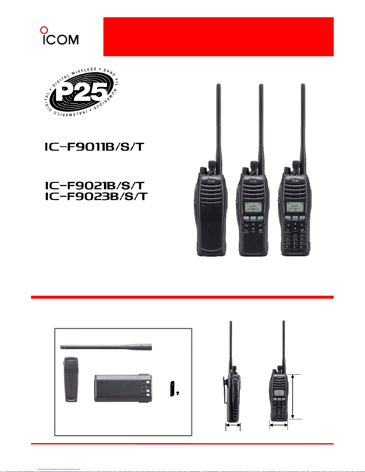
IC-F9011B
“Non-display model”
IC-F9011S
“Simple model”
IC-F9011T
“10-key model”
Supplied Accessories
(May differ according to version)
Dimensions (mm/inch)
Flexible Antenna
(6
9/16
)
5
BP-254
Li-Ion Battery
MB-115
Belt Clip,
Alligator model
Connector
cover
(with screw)
16
7
58.6 (2
5/16
)41.8 (1
21/32
)
2-2 Common Features
APCO P25 Digital migration is now an inevitable trend for Federal, State and Local government users of 2-way
radios. The IC-F9011 series, much more evolved from the IC-F70D series, is not simply enabling migration from
analog to digital but also covers a wide range of features. The standard trunking capability of the IC-F9011
series is outstanding, ensuring smooth communication, despite busy signal traffic. Furthermore the IC-F9011
series has the advanced DVSI AMBE+2
TM
enhanced vocoder, resulting in clear speech audio.
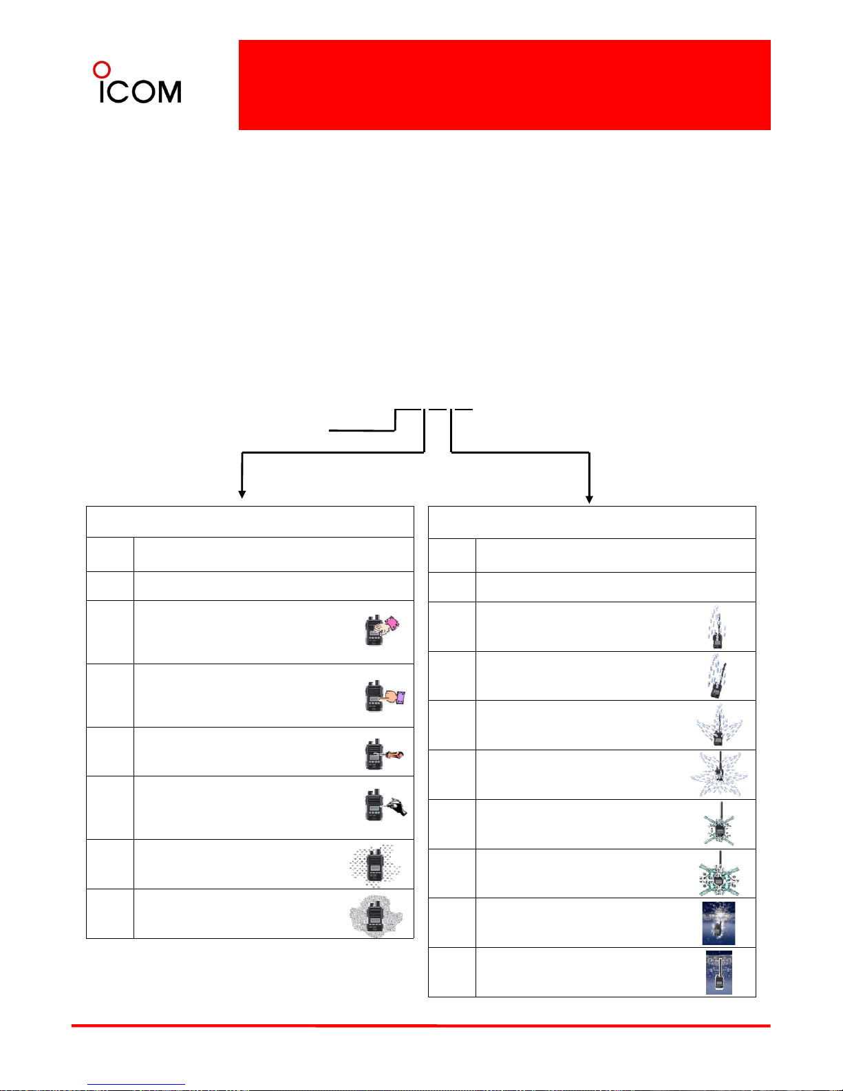
APCO P25 DIGITAL RADIO SYSTEM – Conventional and Trunking in one radio !
P25 Conventional and Trunking
The IC-F9011 series includes P25 conventional
and trunking capabilities as standard. You can
assign individual channels to conventional
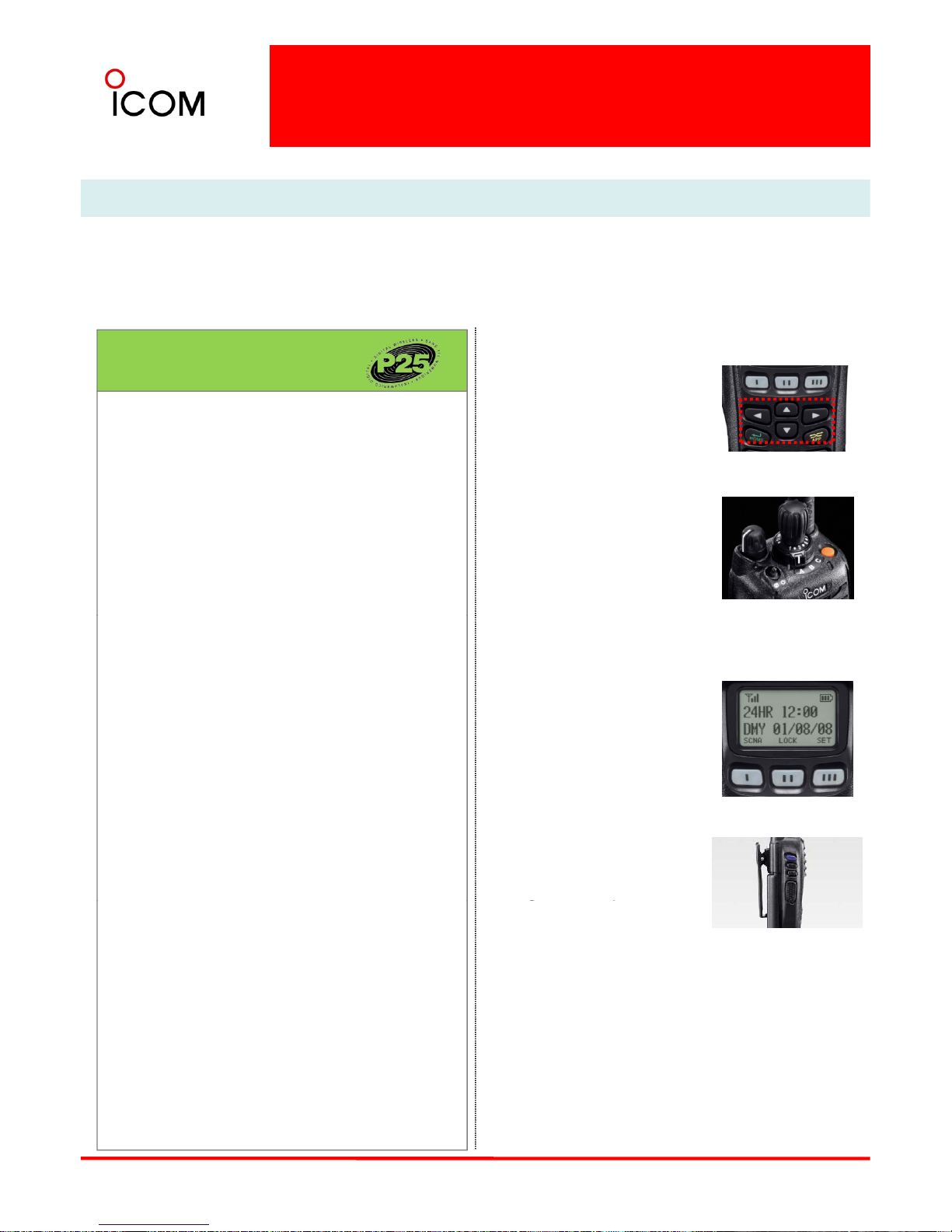
4-way navigation cross keypad
The 4-way cross keypad* on
the front panel provides an
intuitive user interface.
* IC-F9011T/S and IC-F9021
T/S only.
APCO 25 [P25] Digital Features
analog, conventional P25 or P25 trunking, all
within one radio.
Interoperability
The IC-F9011 series have passed CAP
(Compatibility Assessment Program) and proved
to provide interoperability with other brand P25
trunked infrastructure for public safety
Encryption button and 3
position zone select
switch
On the top of the radio, there
is a toggle switch to turn the
encryption on or off* and the
3-position switch allows you to
quickly select an operating
zone*.
applications. The IC
-
F9011 series
conforms to
the standard specifications for TIA-102, CAAB-B,
Digital C4FM Transceiver Performance
recommendations.
Digital/Analog mixed -mode operation
Mixed-mode operation allows you to detect and
receive both analog FM and P25 digital modes
* According to the programming setting
.
Large dot-matrix display
The IC-F9011T/S and F9021T/S have a large dotmatrix display to show various
operating controls at a glance.
At the bottom line of the
display, the key indicator
and to transmit either mode depending
on programming.
Individual ID and talkgroup ID
The IC-F9011T/S and IC-F9021T/S have 100
individual ID and 250 talkgroup ID memories. Use
the display to visually select the person or group
you’re going to call.
shows the functions assigned
to the [I], [II] and [III] buttons
for more efficient operation.
Slim dimensions
At only 41.8mm (121/32 in)
thick, the IC-F9011 series is
designed to be a solid and
er
g
onomic shape that will
Optional AES/DES encryption
The IC-F9011 series provides AES and/or DES
encryption for secure conversation with the
optional UT-125 AES/DES encryption unit or
UT-128 DES encryption unit. Versions certified to
FIPS 140-2 Level 1 for AES encryption are
planned for future release.
gp
fit comfortably in your hand.
6W RF output power
The IC-F9011 series delivers 6W* of high output
power. The supplied 3040mAh (typ.) Li-Ion battery
pack, BP-254, provides 9 hours* of operating
time.
* 5W for IC-F9021T/S/B. Typical operation with
6
Enhanced vocoder ready
Using the DVSI’s AMBE+2™ vocoder, the IC-F9011
series is enhanced vocoder ready.
OTAR (Over-the-Air-Rekeying)
The IC-F9011 series supports P25 OTAR for
changing encryption keys over the air.
T
x: Rx: standby=5:5:90.
Common Features
1000mW audio output power
The built-in BTL amplifier doubles the audio
output power and delivers loud audio to receive
all calls under noisy environments. In addition,
even when using an optional speaker
microphone, the BTL amplifier output is also
available from the external accessory connector
which increases the audio output via the
Optional Man Down unit
With the optional Man Down unit, UT-124R,
the IC-F9011 series automatically sends an
emergency signal when the radio is left in
a horizontal position for a preset time.
Other features
• Wide frequency coverage
p
microphone.
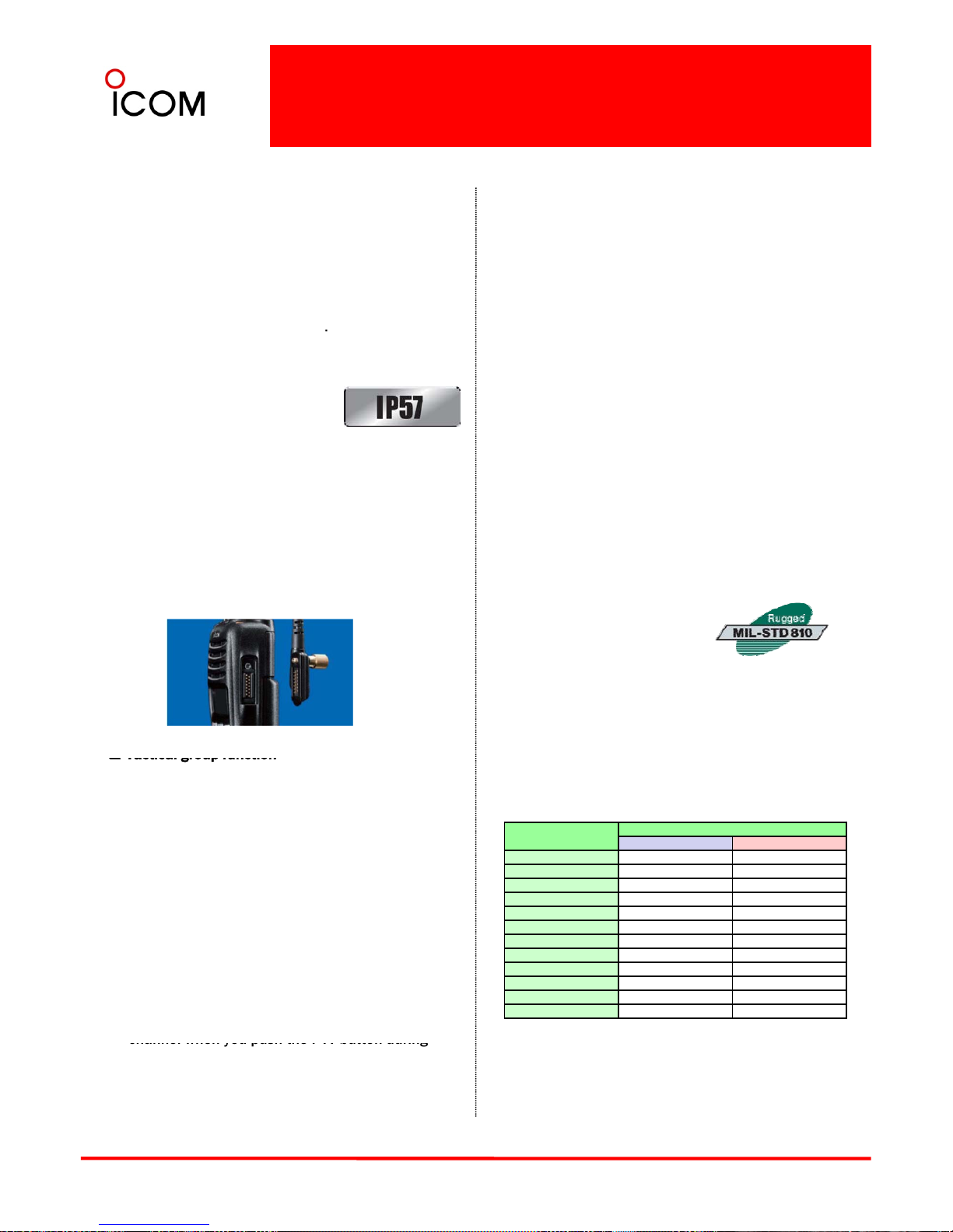
IP57 dust and waterproof protection
The IC-F9011 series features
dust and waterproof protection
equivalent to IP57 and is tested
to demanding MIL-STD 810 requirements. IP57
waterproof protection means the IC-F9011 series
(VHF : 136~174MHz UHF : 400~520MHz)
• FM wide/narrow channel spacing*
• 512 channels/128 zones
• Built-in audio compander*
• Built-in inversion type voice scrambler*
• VOX function for hands-free operation
• Optional waterproof speaker microphone,
HM-184
can be submerged in 1 meter of water for 30
minutes. The radio can withstand rugged use
even under harsh weather conditions.
14-pin accessory connector
The new 14-pin accessory connector enhances
the IC-F9011 series performance and capabilities.
It has reserved pins for programmable key inputs.
• Talk-around function
• CTCSS and DTCS encoder and decoder*
• DTMF autodial*
• 2-Tone encoder and decoder* and MDC 1200
compatible* (Available in the future)
*Analog mode only
Meets MIL
-
STD-810
The MIL-STD-810 series of
standards is issued by the
United States Army's Developmental Test
Command, to specify various environmental tests to
prove that equipment qualified to the standard will
survive in the field. Icom has been tested to and
passed the following MIL-STD requirements and
Tactical group function
The tactical group function allows you to copy
memory channels to the tactical zone and
temporarily regroup memory channels.
Using the optional zone copy cable, memory
channels in the tactical zone can be transferred
from a master radio to other radios.
Abundant scanning settings
Standard
MIL 810F
Method Procedure
Low Pressure 500.4 I, II
High Temperature 501.4 I, II
Low Temperature 502.4-3 I, II
Applicable U.S. Military Specifications
strict environmental standards
.
The dual priority scan monitors two primary
channels alternately, while scanning other
channels. The mode-dependent scan function
automatically changes the scan list according to
the operating channel. The talk-back function
with timer beep, TX channel and cancel channel
settings allow you to preset the transmission
Temperature Shock
503.4
I
Solar Radiation 505.4 I
Rain 506.4 I, III
Humidity 507.4 –
Salt Fog 509.4 –
Dust Blowing 510.4 I
Immersion 512.4 I
Vibration 514.5 I
Shock 516.5 I, IV
7
channel when you push the PTT button during
scanning operation or cancel scanning.
▒
Also meets equivalent MIL
-
STD-810-C, -D and
-
E
.
2-3 IP Classification Codes
Ingress Protection (IP) ratings are developed by the European Committee for Electro Technical
Standardization.
International Standard IEC 60529 outlines an international classification system that describes the
sealing characteristics of electrical equipment. The classification system defines the level of protection
provided by enclosures to prevent the ingress of foreign objects and moisture into the electrical
equipment.
The classification system uses the “IP” code, or “Ingress Protection” code, to define the level of seal. An IP
number contains two numbers (i.e. IP57) in most instances which relate to the level of protection provided
by an enclosure or housing. Either number may be shown as “X” (i.e. IPX6 / IP7X) to indicate the “X” part is
not tested.
IP 5 7
Degrees of Protection (Foreign Bodies) – 1st Digit
Code letters
1st Digit
2nd Digit
Degrees of Protection (Moisture) – 2nd Digit
IP Level Description of Protection Level
0 Not protected
1
Protected against foreign solid objects
of 50 mm diameter and greater
(Protects against a large surface of the
body, such as the back of a hand)
IP Level Description of Protection Level
0 Not protected
1
Protected against vertically falling water
drops
2
Protected
agains
t f
oreign so
lid objects
of 12.5 mm diameter and greater
(Protects against fingers or similar
objects)
3
Protected against foreign solid objects
of 2.5 mm diameter and greater
(Protects against tools, thick wires, etc.)
Protected against foreign solid objects
2
Protected against vertically falling water
drops when enclosure is tilted up to 15º
3
Protected against water sprayed at an
angle up to 60º on either side of the
vertical
4
Protected against water splashed
against the component from any
direction
4
o
f 1.0 mm di
ameter and greater
(Protects against most wires, screws,
etc.)
5
Protected from the amount of dust that
would interfere with normal operation
6
Dust tight
(No ingress of dust; complete protection
5
Protected against water projected in jets
from any direction
6
Protected against water projected in
powerful jets from any direction
Protected against temporary immersion
8
against contact)
7
in water between 15cm and 1m for
30min.
8
Protected against continuous immersion
in water beyond 1m.

2-4 Project 25
What is Project 25?
Project 25 (P25) is a standard for the manufacturing of interoperable digital
2-way wireless communications products. Developed in North America under
state, local and federal representatives and Telecommunications Industry
Association (TIA) governance, P25 is gaining worldwide acceptance for
public safety, security, public service, and commercial applications.
What Are the Benefits of P25?
From the beginning, P25 has targeted four primary
What is Required for P25 Compliance?
At a minimum, a P25 radio system must provide
The published P25 standards suite is administered by the Telecommunications Industry Association (TIA Mobile and
Personal Private Radio Standards Committee TR-8). Radio equipment that demonstrates compliance with P25 is
able to meet a set of minimum requirements to fit the needs of public safety. These include the ability to interoperate
with other P25 equipment, so that users on different systems can talk via direct radio contact. The P25 standard was
created by and for public safety professionals.
objectives:
• Allow effective, efficient, and reliable intra-agency
and inter-agency communications
… so organizations can easily implement
interoperable and seamless joint communication
in both routine and emergency circumstances.
• Ensure competition in system life cycle
int
eropera
bility with th
ese mandatory
P25 Standard
components:
• The Common Air Interface (CAI) specifies how
information is coded, transmitted and received
over the air.
It enables users to interoperate and communicate
digitally across networks, agencies, and vendors.
• The Im
p
roved Mult
i
-
Band Excitation (IMBE)
procurements
… so agencies can choose from multiple vendors
and products, ultimately saving money and
gaining the freedom to select from the widest
range of equipment and features.
• Provide user-friendly equipment
’
p
()
vocoder converts speech into a digital bit stream.
Test panels judged IMBE as the coding scheme
most successful at making male and female
voices audible against background noises such as
moving vehicles, sirens, gunshots, and traffic noise
– the conditions of public safety use. DVSI has
introduced a new low data rate AMBE+2™ vocoder
that sets a new standard for high
-
quality, high
-
…
so users can take full advantage of their radios
lifesaving capabilities on the job – even under
adverse conditions – with minimal training.
• Improve radio spectrum efficiency
… so networks will have enough capacity to handle
calls and allow room for growth, even in areas
where the spectrum is crowded and it’s difficult for
performance speech quality at data rates from 2.0
to 9.6 kbps and Icom IC-F9011 series include this
AMBE+2™ enhanced vocoder.
P25 has also defined standard modes of operation to
enable multi-vendor interoperability for additional
system functions: trunking, encryption, and over-theair rekeying, to name a few.
agencies to obtain licenses for additional radio
frequencies.
What is the Status of P25 Today?
P25 systems are available today and being deployed
globally. Many organizations have mandated that new
land mobile radio system purchases follow P25
standards. P25 is ongoing -- the standard continues to
evolve as the needs of users and the capabilities of
A set of defined system interfaces allow the P25
system elements to communicate with host
computers, data terminals and the public switched
telephone network (PSTN).
Looking to the Future
There are two phases of P25 development:
• Phase 1 is completed.
9
new technology advance. Bo
th
users an
d
manufacturers have an important role to play in
shaping P25.
It
spec
ifies a 12.5 kHz bandwidth.
• Phase 2 is in development.
It will use a 6.25 kHz equivalent bandwidth to
allow better spectrum efficiency and benefit a
greater number of users

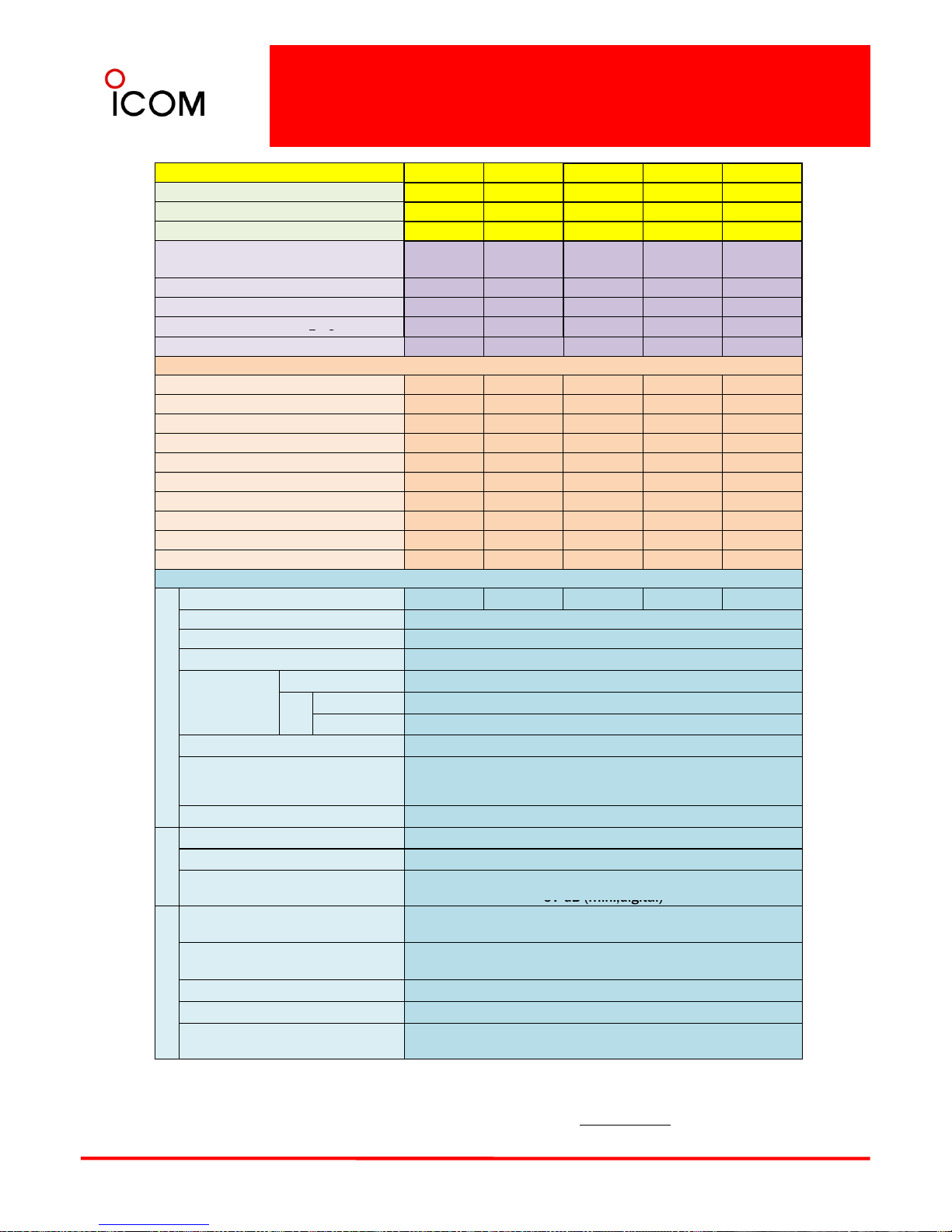
2-5 Function and Specifications
Comparison
Model No. IC-F9011 B IC-F9011S IC-F9011T IC-F9021B IC-F9021B
V
ersion
#01
#05
#10
#01
#21
Destinations
USA-01 USA-01
USA-01 USA-02 USA-03
Keypad Model No Simple Full No No
Supplied Battery
BP-254
3040mAh
BP-254
3040mAh
BP-254
3040mAh
BP-254
3040mAh
BP-254
3040mAh
Supplied Antenna FA-S65V FA-S65V FA-S65V FA-S58U FA-S75U
Type Approval FCC FCC FCC FCC FCC
*
*
FIPS 140
2 Certified
1 3
Intrinsically Safe
--
---
Function Comparison
CTCSS
✔✔✔✔✔
DTCS
✔✔✔✔✔
2-Tone
*1
----5-Tone ----DTMF Autodial
✔✔✔✔✔
DTMF Decoder ----MDC 1200
*1
----
-
APCO P25 Digital Conventional
✔✔
✔
✔✔
APCO P25 Digital Trunking
✔✔✔✔✔
OTAR
✔✔✔✔✔
SPECIFICATIONS - Measurements made in accordance with EIA-152-C/204D, TIA-603 B (analog).
Frequency Range (MHz) 136-174 400~470 450~520
GENERAL
Number of Channels
512 ch / 128 zones
Channel Spacing (kHz) 12.5 (digital), 15/30 (analog)
12.5 (digital),
12.5/25 (analog)
PLL Channel Step (Unit: kHz)
2.5 / 3.125
Current drain
Tx High
2.2A 2.1A
Rx
Stand-by
300mA 300mA
Max. audio
800mA 800mA
Operating Time
*2
9 hours (with BP-254)
Dimensions (W×H×D)
(projections not included)
58.6×167×41.8 mm
2
5
⁄
16
×
6
9
⁄
16
×
1
21
⁄32in
Weight (approx.) 533g; 1.17lb
(with BP-254)
TX
RF Output Power (High) 6W 5W
Spurious Emissions 78dB
(typ.)
80dB
(typ.)
Adjacent Channel Power (W/N)
70/60dB (
min.,analog
),
67dB (min.,digital)
RX
Sensitivity (at 12dB SiNAD)
0.25μV (typ., analog)
0.30μV (typ.,digital)
Adjacent Channel Selectivity
(W/M) FM(Analog), Digital(P25)
FM80/70dB
(typ.),
P25 60dB (typ.)
FM76/70dB
(typ.),
P25 60dB (typ.)
Spurious Response Rejection 80dB (typ.)
10
Intermodulation
R
ejection
75dB
(typ.)
AF Output Power (at 5% distortion
with an 8Ω load)
1000mW
(typ.)
*1. Planned to be available in the future
*2 . Operating time is approximate time (at 20ºC). Tx: Rx: standby=5:5:90. Power save on.
*3. Depending on version.
Model No. IC-F9021S IC-F9021S IC-F9021T IC-F9021T IC-F9023B
Function and Specifications
Comparison
V
ersion
#
0
5#
25#10
#30
#02
Destinations
USA-02 USA-03
USA-02 USA-03 EXP-02
Keypad Model Simple Simple Full Full No
Supplied Battery
BP-254
3040mAh
BP-254
3040mAh
BP-254
3040mAh
BP-254
3040mAh
BP-254
3040mAh
Supplied Antenna
FA-S58U FA-S75U FA-S58U FA-S75U FA-S58U
Type Approval FCC FCC FCC FCC -
*
*
FIPS 140
2 Certified
1 3
Intrinsically Safe
--
-- -
Function Comparison
CTCSS
✔✔✔✔✔
DTCS
✔✔✔✔✔
2-Tone
*1
----5-Tone ----DTMF Autodial
✔✔✔✔✔
DTMF Decoder ----MDC 1200
*1
----
-
APCO P25 Digital Conventional
✔✔
✔✔
✔
APCO P25 Digital Trunking
✔✔
✔✔
✔
OTAR
✔✔✔✔✔
SPECIFICATIONS - Measurements made in accordance with EIA-152-C/204D, TIA-603 B (analog).
Frequency Range (MHz) 400 ~ 470 450 ~ 520 400 ~ 470 450 ~ 520 400 ~ 470
GENERAL
Number of
Ch
annels
512 ch/128
zones
Channel Spacing (kHz) 12.5 (digital) / 12.5/25 (analog)
PLL Channel Step (Unit: kHz)
2.5 / 3.125
Current Drain
Tx High
2.1A
Rx
Stand-by
300mA
Max. audio
800mA
Operating Time
*2
9hours
(with BP-254)
Dimensions (W×H×D)
(projections not included)
58.6×167×41.8 mm
2
5
⁄
16
×
6
9
⁄
16
×
1
21
⁄32in
Weight (approx.) 533g; 1.17lb
(with BP-254)
TX
RF Output Power (High) 5W
Spurious Emissions 80dB
(typ.)
Adjacent Channel Power (W/N)
70/60dB (min.,analog)
67 dB (
min.,digital
)
RX
Sensitivity (at 12dB SINAD)
0.25μV (typ., analog)
0.30μV (typ.,digital)
Adjacent Channel Selectivity
(W/M) FM(Analog), P25(Digital)
FM76/70 dB (typ.)
P25 60 dB (typ.)
Spurious Response Rejection 80dB (typ.)
Intermodulation Rejection 75dB
(typ.)
AF Output Power (at 5% distortion
11
with an 8Ω load)
1000mW
(typ.)
*1. Planned to be available in the future
*2. Operating time is approximate time (at 20ºC). Tx: Rx: standby=5:5:90. Power save on.
*3. Depending on version.
▒ NOTE: The UHF IC-F9021S/B/T series that covers frequency range from 380 to 450 MHz is planned to be
▒ released in the future.

Model No. IC-F9023S IC-F9023S IC-F9023T IC-F9023T
Function and Specifications
Comparison
V
ersion
#06
#26
#11
#31
Destinations
EXP-02
EXP-03 EXP-02 EXP-03
Keypad Model Simple Simple Full Full
Supplied Battery
BP-254
3040mAh
BP-254
3040mAh
BP-254
3040mAh
BP-254
3040mAh
Supplied Antenna FA-S58U FA-S75U FA-S58U FA-S75U
Type Approval - - - -
*
*
FIPS 140
2 Certified
1 3
Intrinsically Safe - - - -
Function Comparison
CTCSS
✔✔ ✔ ✔
DTCS
✔✔ ✔ ✔
2-Tone
*1
-- - 5-Tone - - - DTMF Autodial
✔✔ ✔ ✔
DTMF Decoder - - - MDC 1200
*1
-- - APCO P25 Digital Conventional
✔✔ ✔ ✔
APCO P25 Digital Trunking
✔✔ ✔ ✔
OTAR
✔✔ ✔ ✔
SPECIFICATIONS - Measurements made in accordance with EIA-152-C/204D, TIA-603 (analog).
Frequency Range (MHz) 400~470 450~520 400~470 450~520
GENERAL
Number of Channels
512 ch / 128 zones
Channel Spacing (kHz) 12.5 (digital) / 12.5/25 (analog)
PLL Channel Step (Unit: kHz)
2.5 / 3.125
Current drain
Tx High
2.1A
Rx
Stand-by
300mA
Max. audio
800mA
Operating Time
*3
9hours
(with BP-254)
Dimensions (W×H×D)
(projections not included)
58.6×167×41.8 mm
2
5
⁄
16
×
6
9
⁄
16
×
1
21
⁄32in
Weight (approx.) 533g; 1.17lb
(with BP-254)
TX
RF Output Power (High) 5W
Spurious Emissions 80dB
(typ.)
Adjacent Channel Power (W/N)
FM (Analog), P25(Digital)
70/60dB
(min.,analog)
67 dB (min.,digital)
RX
Sensitivity (at 12dB SINAD)
0.25μV (typ
.,
analog)
0.30μV (typ.,digital)
Adjacent Channel Selectivity (W/M)
FM76/70 dB (typ.)
P25 60 dB (typ.)
Spurious Response Rejection 80dB (typ.)
Intermodulation Rejection 75dB
(typ.)
AF Output Power
(at 5% distortion with an 8Ω load)
1000mW
(typ.)
12
*1. Planned to be available in the future
*2. Operating time is approximate time (at 20ºC). Tx: Rx: standby=5:5:90. Power save on.
*3. Depending on version.
3 Accessories
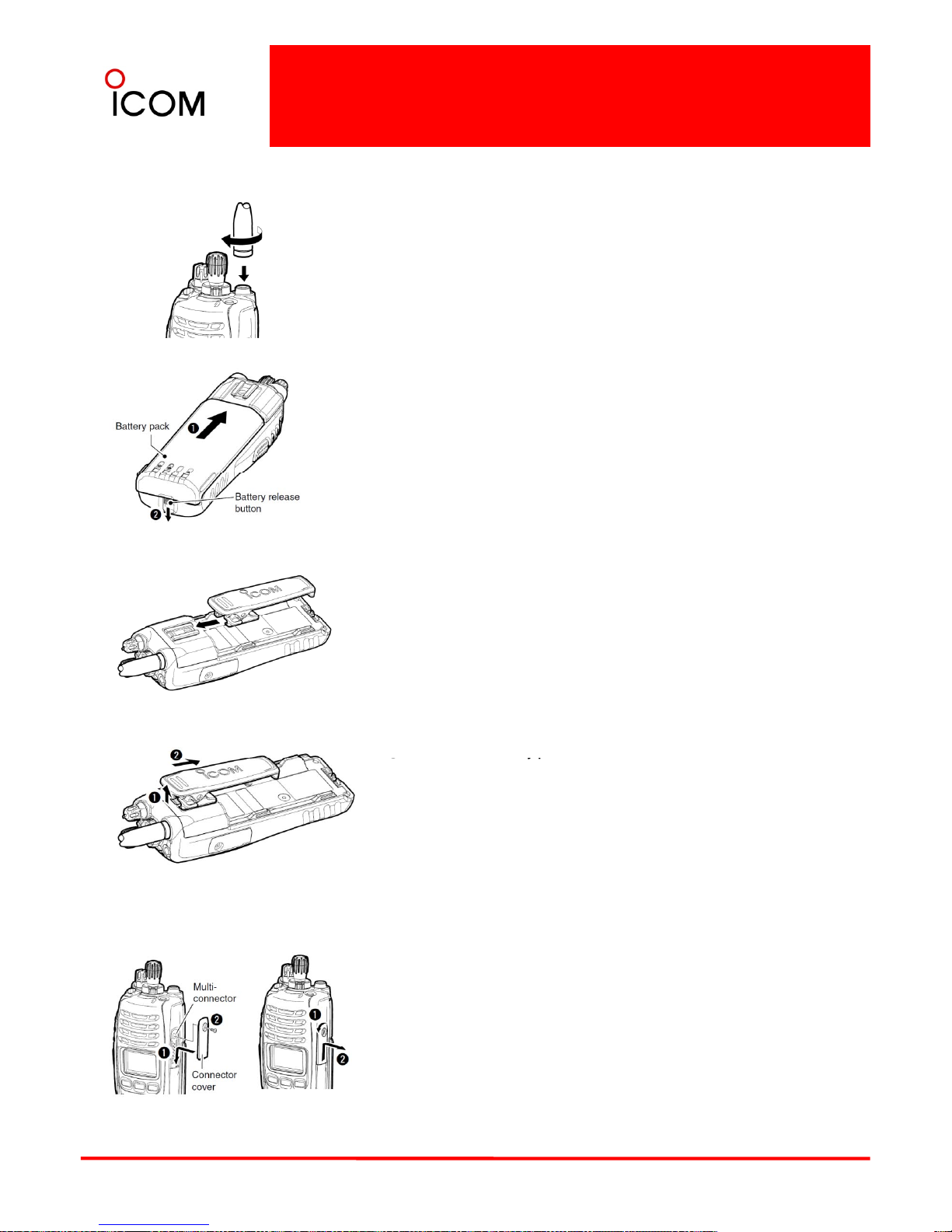
3-1 Supplied Accessory Attachments
Attach the supplied accessories as shown below.
Flexible antenna
Connect the supplied flexible antenna to the antenna connector.
CAUTION:
▒• NEVER carry the transceiver by holding the antenna.
▒• DO NOT connect the antenna other than those listed on 3-3-6
▒ Other Options.
▒• Transmitting without an antenna may damage the transceiver.
Battery pack
To attach the battery pack:
Slide the battery pack on the back of the transceiver in
the direction of the arrow (➊), then lock it with the
battery release button.
• Slide the battery pack until the battery release button
‘
’
makes a click sound.
To release the battery pack:
Slide the battery release button in the direction of the
arrow (➋) as shown below. The battery pack is then
released.
▒ NEVER release or attach the battery pack when the
▒ transceiver is wet or soiled. This may result water or
▒ dust access to the transceiver/battery pack and may
▒ result in the transceiver being damaged
.
▒ NOTE: Keep the battery pack terminals clean. It’s a
▒ good idea to clean the battery pack terminals once a
▒ week.
Belt clip
To attach the belt clip:
①
Release the battery pack if it is attached.
①
yp
② Slide the belt clip in the direction of the arrow until the belt clip
is locked and makes a ‘click’ sound.
To detach the belt clip:
① Release the battery pack if it is attached.
② Pinch the clip (➊), and slide the belt clip in the direction of
the arrow (➋).
Connector cover
Attach the connector cover when optional equipment is not used.
To attach the connector cover:
①Insert the connector cover into the multi-connector.
②Tighten the screw, using a Philips screwdriver.
▒ CAUTION:
▒ Attach the connector cover when the optional equipment
▒ is not used. Otherwise the terminals of the multi-connector may be
13
▒ shorted by metal objects, et
c., an
d this
cou
ld d
amage
the
▒ transceiver.
To detach the connector cover:
①Unscrew the screw, using a Phillips screwdriver.
②Detach the connector cover for the optional equipment connector.
Connector cover.
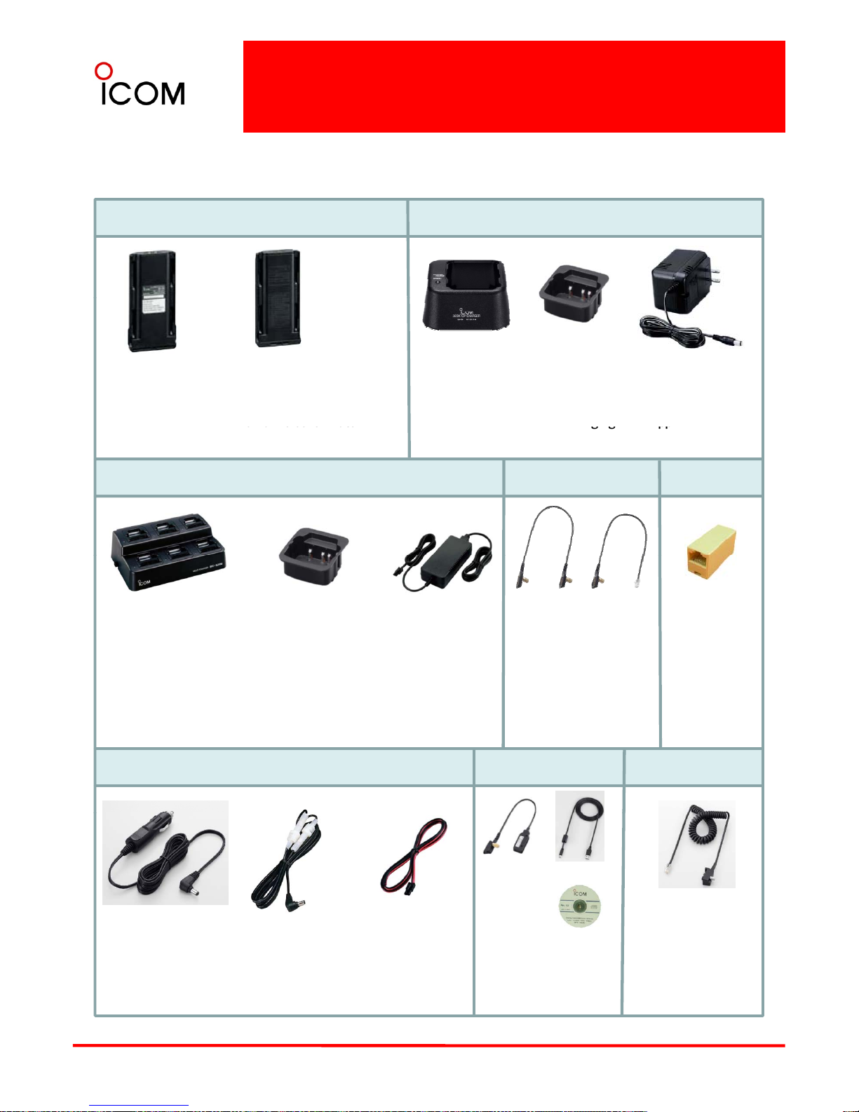
3-2 Optional Accessories
The optional accessories available with IC-F9011 series is shown below. Ask your Icom distributor for further
*BATTERY PACKS and CASE
details if required. (Some options may not be available for all countries.)
*DESKTOP CHARGER
BP-254
Li-Ion BATTERY PACK,
7.4V/3040mAh
BC-119N DESKTOP CHARGER + AD-110 CHARGER
ADAPTER + BC-145SA AC ADAPTER Rapidly charges
the BP
-
253 or BP-254. Charging time: approx. 4.0
▲ BC-145SA▲ BC-119N
▲AD-110
BP-237
BATTERY CASE
AA (LR6)x6
2900mAh(min)
3040mAh(typ)
gg pp
hours when BP-253 is attached.
ZONE COPY CABLES
alkaline cells. Water
resistant equivalent to IPX4
MULTI-CHARGER
Connector
BC-121N MULTI-CHARGER + AD-110 CHARGER
ADAPTER + BC-157 AC ADAPTER
▲AD-110 (6 pcs).
▲ BC-121N
▲ BC-157
OPC-1871
Handheld to
mobile
CABLE
OPC-1870
Handheld
to handheld
CABLE
5610000270
ALA651B
8 pin connector
for modular
Rapidly charges up to 6 battery packs (Six AD-110s
are required). Charging time: approx.4.0 hours when
BP-253 is attached.
POWER SUPPLY CABLES
INTERFACE CABLE
KEYLOADER CABLE
plugs (use with
Key Loader
cables)
OPC-656
OPC-1862
OPC-1534
OPC-1862
OPC-1637
14
CP-23L
CIGARETTE
LIGHTER CABLE
For use with
BC-119N
OPC-515L
DC POWER CABLE
For use with BC-119N.
DC POWER
CABLE For use
with BC-121N.
PC (USB) INTERFACE
CABLE/CLONE CABLE
packed with OPC-1637
and USB driver CD.
*Refer to the “3-3 OPTIONAL ACCESSORIES INSTALLATION” section of this handbook.
KEYLOADER CABLE
to KVL 3000 PLUS
to install encryption
keys (Must be used
with OPC-1871)
Optional Accessories
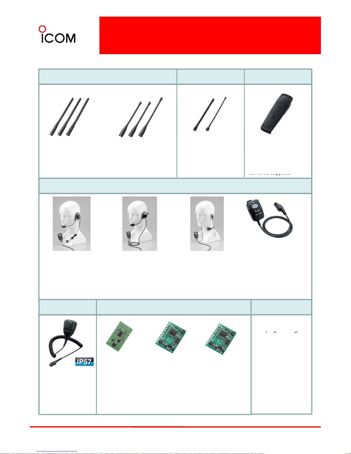
ANTENNAS
CUT ANTENNA
BELT CLIP
MB-115 : Alligator
model to fit up to 60mm
(2
3/8
Inch ) width belt.
FA-S25V : 136–148MHz
FA-S65V : 148–160MHz
FA-S66V : 160–174MHz
FA-S67VC : 136–174MHz
FA-S76UC : 380–520MHz
FA-S30U : 380–430MHz
FA-S58U : 430–470MHz
FA-S75U : 470–520MHz
HEADSETS and PTT/VOX UNIT
Same as supplied.
HS-94 : Earhook headset
with flexible boom
microphone. Approved
option for intrinsically
*VS-1MC : PTT/VOX unit.
Required when using these
headsets with the
transceiver. Approved
HS-97 : Throat microphone
fits around the neck and
picks up speech vibration.
Approved option for
HS-95 : Behind-the-head
headset with flexible
boom microphone.
Approved option for
safe versions. option for intrinsically safe
versions.
intrinsically safe versions. intrinsically safe versions.
*INTERNAL UNITS
*SPEAKER-MIC
CLONING SOFTWARE
CS-F9511 EXP #01:
For
prog
ramming all
▒ The pictures of headset shown above include optional VS-1MC PTT/VOX unit.
UT-125
AES/DES
ENCRYPTION UNIT
Provides AES and
UT-124 R
MAN DOWN UNIT :
Automatically sends
an emergency signal
HM-184 : Rugged
model speaker
-
pg g
versions of the
IC-F9011/F9023
series VHF/UHF
HANDHELD
TRANSCEIVERS.
UT-128
DES
ENCRYPTION UNIT
Provides
15
DES encryption
capabilities
when the
transceiver is left in
a horizontal for a
preset time
microphone.
Equivalent to IP57.
DES encryption
capabilities
*Refer to the “3-3 OPTIONAL ACCESSORIES INSTALLATION” section of this handbook.

3-3 Optional Accessories Installation
3-3-1 Battery/Battery Charging - Caution
■ Caution
Misuse of Lithium-Ion batteries may result in the
following hazards: smoke, fire, or the battery may
rupture. Misuse can also cause damage to the battery
or degradation of battery performance.
DANGER! Use and charge only specified Icom
battery packs with Icom radios or Icom chargers.
• DANGER! If fluid from inside the battery gets in
your eyes, blindness can result. Rinse your eyes
with clean water, without rubbing them, and see a
doctor immediately.
• WARNING! Immediately stop using the battery if it
emits an abnormal odor, heats up, or is discolored
Only Icom battery packs are tested and approved
for use and charge with Icom radios or Icom
chargers. Using third-party or counterfeit battery
packs or chargers may cause smoke, fire, or cause
the battery to burst.
◇Battery caution
• DANGER! DO NOT hammer or otherwise impact
or deformed. If any of these conditions occur,
contact your Icom dealer or distributor.
• WARNING! Immediately wash, using clean water,
any part of the body that comes into contact with
fluid from inside the battery.
• WARNING! NEVER put the battery in a microwave
the battery. Do not use the battery if it has been
severely impacted or dropped, or if the battery has
been subjected to heavy pressure. Battery damage
may not be visible on the outside of the case. Even
if the surface of the battery does not show cracks
or any other damage, the cells inside the battery
may rupture or catch fire.
oven, high
-
pressure container, or in an induction
heating cooker. This could cause a fire, overheating,
or cause the battery to rupture.
• CAUTION! Always use the battery within the
specified temperature range for the transceiver (–
30˚C to +60˚C; –22˚F to +140˚F) and the battery
itself (–20˚C to +60˚C; –4˚F to +140˚F). Using
• DANGER! NEVER use or leave battery packs in
areas with temperatures above +60˚C (+140˚F).
High temperature buildup in the battery, such as
could occur near fires or stoves, inside a car heated
car, or in direct sunlight may cause the battery to
rupture or catch fire. Excessive temperatures may
also degrade battery performance or shorten
(
)g
the battery out of its specified temperature range
will reduce the battery’s performance and battery
life.
• CAUTION! Shorter battery life could occur if the
battery is left fully charged, completely discharged,
or in an excessive temperature environment (above
˚
˚
battery life
.
• DANGER! DO NOT expose the battery to rain,
snow, seawater, or any other liquids. Never charge
or use a wet battery. If the battery gets wet, be sure
to wipe it dry before using.
• DANGER! NEVER incinerate used battery packs
+45 C; +113 F) for an extended period of time. If
the battery must be left unused for a long time, it
must be detached from the radio after discharging.
You may use the battery until the remaining
capacity is about half, then keep it safely in a cool
dry place with the temperature range as below;
–20˚C to +45˚C (–4˚F to +113˚F) (within a month)
–20˚C to +35˚C (–4˚F to +95˚F) (within three
˚
˚
˚
˚
since interna
l batt
ery gas may cause
them to
rupture, or may cause an explosion.
• DANGER! NEVER solder the battery terminals
and NEVER modify the battery pack. This may
cause heat generation, and the battery may
rupture, emit smoke or catch fire.
months)
–
20 C to +25 C (
–
4 F to +77 F) (within a
year)
◇Charging caution
• DANGER! NEVER charge the battery pack in
areas with extremely high temperatures, such as
near fires or stoves, inside a sun heated car, or in
direct sunlight. In such environments, the
16
• DANGER! Use the battery only with the
transceiver for which it is specified. Never use a
battery with any other equipment, or for any
purpose that is not specified in this instruction
manual.
safety/protection circuit in the battery will activate,
causing the battery to stop charging.

Battery/Battery Charging - Caution
• WARNING! NEVER charge or leave the battery in
the battery charger beyond the specified time for
charging. If the battery is not completely charged
by the specified time, stop charging and remove
the battery from the battery charger. Continuing to
charge the battery beyond the specified time limit
may cause a fire, overheating, or the battery may
rupture.
p
• WARNING! NEVER insert the transceiver (battery
attached to the transceiver) into the charger if it is
wet or soiled. This could corrode the battery
charger terminals or damage the chargers. The
chargers are not waterproof.
•
CAUTION! NEVER
charge the battery outside of the
specified temperature range: 0˚C to +40˚C (+32˚F
to +104˚F). Icom recommends charging the
battery at +20˚C (+68˚F). The battery may heat up
or rupture if charged out of the specified
temperature range. Additionally, battery
performance or battery life may be reduced.
17
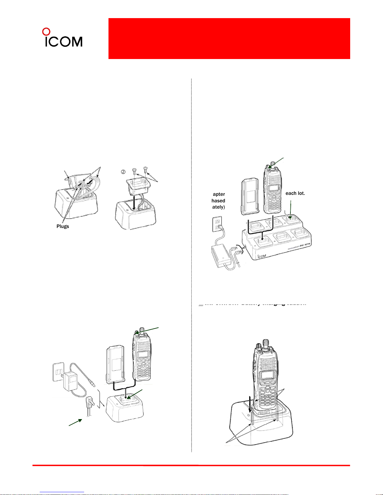
3-3-2 Battery Charging
■ Optional battery chargers
AD-110 installation
The AD-110 charger adapter must be installed into
the BC-119N or BC-121N before battery charging.
➥ Connect the AD-110 charger adapter and the BC-
119N/BC-121N as below, then install the
AD-110 into the holder space of the BC-119N or
Rapid charging with the BC-121N+AD-110
The optional BC-121N allows up to 6 battery packs to
be charged simultaneously. Charging period: Approx.
4 hours (with BP-254)
The following items are additionally required.
• Six AD-110 charger adapters (purchase separately)
• An AC adapter (BC-157) or the DC power cable
Screws
AD-110
Connectors
c
d
BC-121N with the supplied screws.
(OPC
656)
TRANSCEIVER
Turn Power OFF
BATTERY
PACK
AD-110
charger
adapters are
installed in
supplied with
the charger
adapter
Plugs
AC adapter
(Purchased
separately)
each lot.
This illustration shows the BC-119N.
Rapid charging with the BC
119N+AD
110
The optional BC-119N provides rapid charging of the
Li-Ion battery pack. Charging period: Approx. 4 hours
(with BP-254)
The following items are additionally required.
• AD-110 charger adapter (purchase separately)
• An AC adapter (may be supplied with BC-119N
depending on version) or the DC power cable
DC power cable (OPC-656)
(Connect with the DC power supply;
13.8 V/at least 7 A)
AC adapter
(Not supplied with
some versions.)
▒
IMPORTANT: Battery charging caution
▒ Ensure the guide tabs on the battery pack are
▒ correctly aligned with the guide rails inside
▒ the charger adapter.
▒ (This illustration is described with the BC-119N).
(OPC
-
515L/CP
-
17L)
.
TRANSCEIVER
Turn Power OFF
BATTERY
PACK
AD-110 charger
adapter is installed
in BC-119N.
Tabs
18
Optional OPC-515L (for 13.8 V
power source) or CP-17L (for 12
V cigarette lighter socket) can
be used instead of the AC
adapter.
Guide rails
▒ NOTE : Factory
▒ installed version
▒ available at Icom
▒ America with
▒ product code
▒ BC119N 61
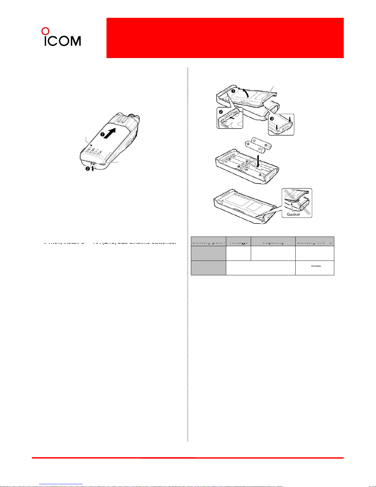
3-3-3 Battery Pack and Case
■ Supplied battery pack (BP-254)
This is one of the supplied accessories. Attach it to
the radio according to the instructions in 3-1
Supplied Accessories Attachments.
Fig.1
BP-237
Latch
Fig.3
Fig.2
Battery pack
Battery release
button
■ Optional battery case (BP-237)
The optional battery case uses 6 × AA (LR6) size
alkaline batteries. Using alkaline batteries results in
lower output power.
1Hook your finger under the latch, and open the
cover in the direction of the arrow (). (Fig.1)
×
*
2
Then, install 6
AA (LR6) size alkaline batteries.
(Fig.2)
• Install the alkaline batteries only.
• Be sure to observe the correct polarity.
• The ribbon should be accessible with the
batteries installed.
3Close the cover in the direction of the arrow ()
first, then check that the latch is in place ().
*1 The BP-254 meets IPX7* requirements for
waterproof protection. When it is connected, the
Battery pack
Voltage
Capacity
Battery life 3
BP-254
*1
7.4V
2900 mAh(min.)
3040 mAh(typ.)
9.5 hrs.
BP-237
*2
Battery case for
A6 x AA (LR6) alkaline
*4
(Fig.1)
• Be sure the gasket is aligned correctly, and does
not protrude from the battery case. (Fig.3)
▒ CAUTION:
▒ •When installing batteries, make sure they are all
▒ the same brand, model and capacity. Also, do not
▒ use new and old batteries together.
transceiver complies with IPX7.
*2 The BP-237 meets IPX4* requirements for splash
resistance. When it is connected, the transceiver
complies with IPX4.
*3 When the power save function is turned ON, and the
operating periods are calculated under the following
conditions; TX : RX : standby = 5 : 5 : 90
*4 Operating period depends on the alkaline cells used.
▒
•Keep battery contacts clean. It’s a good idea to
▒ clean battery terminals once a week.
▒•Never incinerate used battery cells since internal
▒ battery gas may cause them to rupture.
▒•Never expose a detached battery case to water.
▒ If the battery case gets wet, be sure to wipe it dry
▒ before using it.
▒ NOTE:
▒* Once these items have been dropped, the IP rating
▒ cannot be guaranteed because of possible damage
▒ to these cases or the waterproof seal.
19
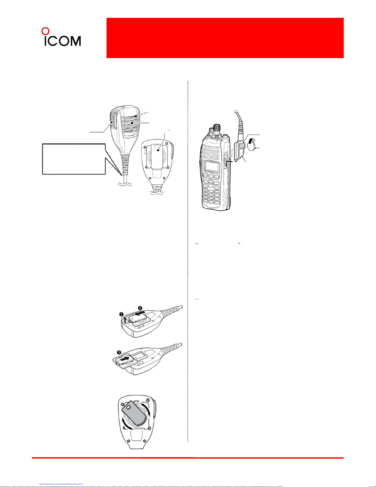
3-3-4 Speaker Microphone
■ Optional Speaker Microphone (HM-184)
To attach
Attach the connector of the speaker-microphone into
the multi-connector on the transceiver and tighten the
screw.
PTT SWITCH
Push and hold to
Transmit;
Microphone
Speaker
Belt cli
p
CAUTION: Attach the speakermicrophone’s connector
securely to prevent accidental
Coin
Screw
Turn the transceiver
power OFF before
connecting
the HM-184.
Release to receive
p
NEVER immerse the connector in water. If the
connector becomes wet, be sure to dry it BEFORE
attaching it to the transceiver.
▒ NOTE: The microphone is located at the top of the
▒ IMPORTANT: KEEP the connector cover attached to
▒ the transceiver when the speaker-microphone is not
▒ in use.
▒
Water will not get into the transceiver even if the
d
ropping, or water intrusion in
the connector.
▒ speaker
-
microphone, as shown in the diagram above.
▒ To maximize the readability of your transmitted
▒ signal (voice), hold the microphone approx. 5 to 10
▒ cm (2 to 4 inches) from your mouth, and speak ing
▒ at normal voice level.
▒ g
▒ cover is not attached, however, the terminals (pins)
▒ will become rusty, or the transceiver will function
▒ abnormally if the connector becomes wet.
Attaching/Detaching belt clip
▒ The HM-184 meets IP57 requirements for
▒ waterproof protection. When it is connected, the
▒ transceiver complies with IP57. Once these items
To detach the belt clip:
1 Pinch the clip ().
2 Then slide the belt clip
in the direction of the
arrow ().
To attach the belt clip:
Slide the belt clip in the
▒
have been dropped, the IP rating cannot be
▒ guaranteed because of possible damage to these
▒ cases or the waterproof seal.
direction of the arrow ()
until the belt clip is locked
and makes a ‘click’ sound.
The clip rotates 360 degrees in 45-degree steps.
20
3-3-5 Optional VS-1MC VOX/PTT Unit
[S]
Push
[T]
■ Optional VOX/PTT Unit (VS-1MC)
The VS-1MC is a VOX/PTT unit for Icom handheld
transceivers, and allows you hands-free operation.
An optional headset (HS-94, etc.) is required for
operation.
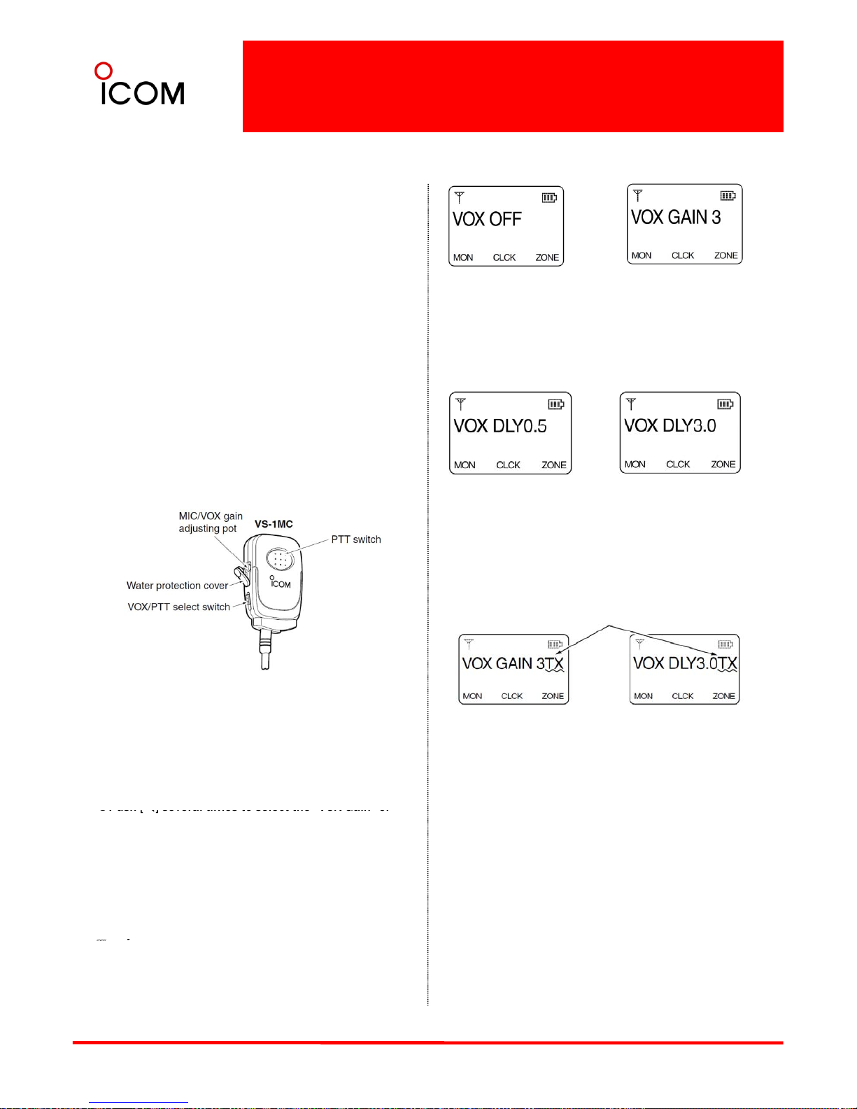
• The VOX (Voice Operated Transmission) function
VOX gain level 3
(default)
VOX function is OFF
• VOX Delay
The VOX delay time can be set from 0.5 to 3.0 sec
(0.5 sec step) for a convenient interval before
returning to receive.
[S]
starts transmission without pushing PTT switch when
you speak into the microphone; then, automatically
returns to receive when you stop speaking.
Features
➥ 14-pin spring-plug model head SP/MIC plug is
equipped
➥ Water-resistant construction
0.5 sec (min.)
(default)
3.0 sec (max.)
Push
[T]
➥ Durable construction
➥ Equipped with a PTT switch and revolving clip
▒
If your voice is detected, “TX” appears on the LCD
▒ as shown below during the VOX gain or VOX delay
▒ adjustment. (The transceiver does not transmit.)
▒
▒
▒
▒
▒
Appear
▒
▒
▒
▒ NOTE : MIC/VOX gain can be adjusted via the
▒ adjusting pot using a thin screwdriver.
▒ The VS-1MC VOX/PTT CASE can be connected to the
VOX delay adjustment
VOX gain adjustment
VOX gain and delay adjustment
cAttach the connector of the VS-1MC into the multi-
connector on the transceiver and tighten the screw.
• Toggle the VOX/PTT select switch to [VOX].
dEnter user set mode.
“
”
▒ following Head Set
.
▒ •HS-94 : Ear-hook model
▒ •HS-95 : Neck-arm model
▒ •HS-97 : Throat microphone
▒ VS-1MC : VOX/PTT switch box for hands-free
▒ operation, etc. has IPX4* waterproof protection.
▒ When in use, the transceiver’s waterproof rating
e
Push [
W
] several times to select the VOX Gain or
“VOX Delay” items. Then, push [S] or [T] to set the
desired level/condition.
fPush and hold [W] again to exit the user set mode.
• Until power is turned OFF, [W], [S] and [T] do not
activate their assigned key functions.
▒ These adjustments are for Simple/10-key models
▒
only.
21
▒ meets IPX4 when it is connected
.
▒ Once these items have been dropped, the IP rating
▒ cannot be guaranteed because of possible damage
▒ to these cases or the waterproof seal.
▒ y
• VOX Gain
The VOX sensitivity level can be adjusted from OFF or 1
to 6 (more sensitive).
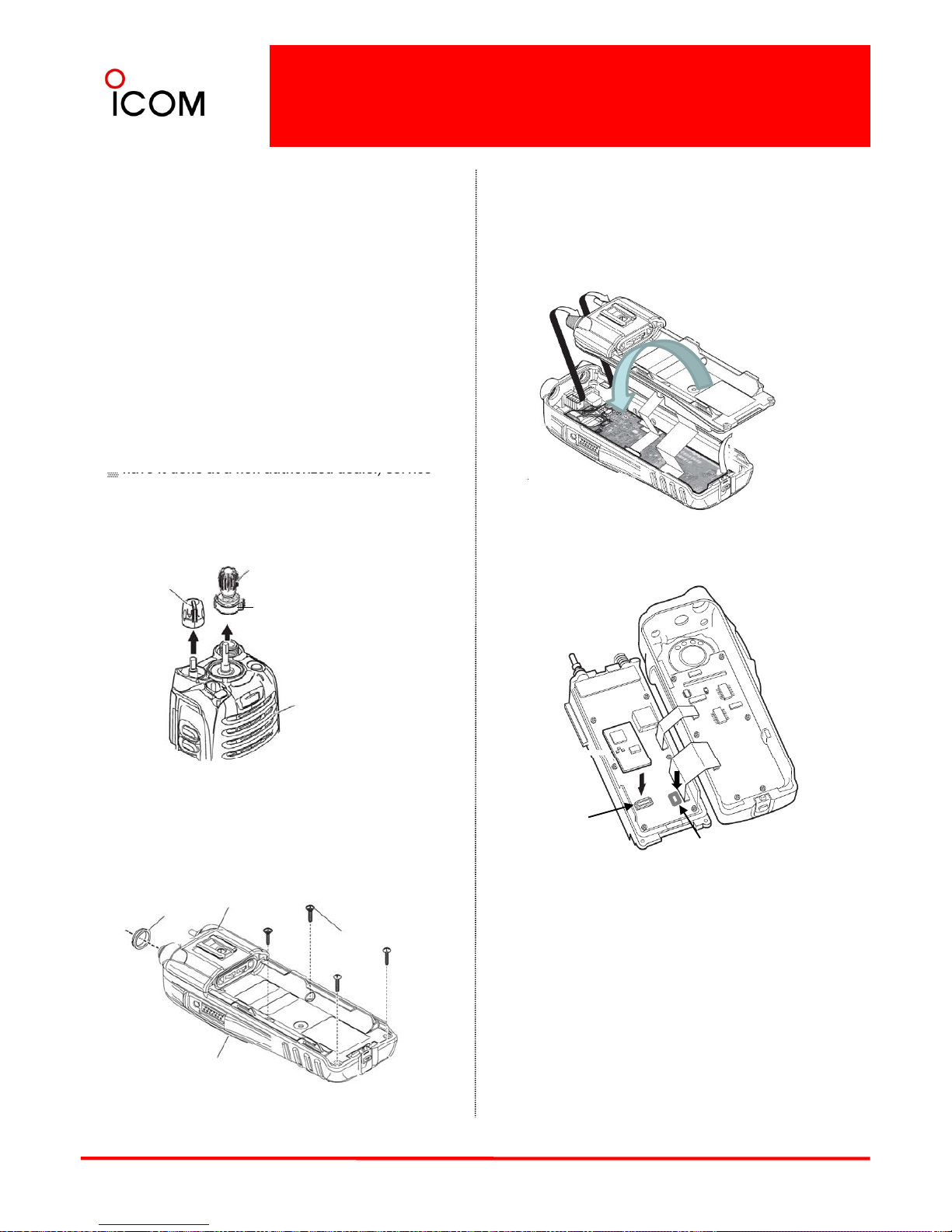
3-3-6 Optional Internal Unit Installation
Unit Installation
4Turn the rear panel as below. No need to detach
the flexible cables
The optional units add useful features to the
IC-F9011 series. The optional units available with
the IC-F9011 series are as follows. (See 3-2 Optional
Accessories.)
▪ UT
-
124R Man Down Unit
▪ UT-125 AES/DES Encryption Unit
▪ UT-128 DES Encryption Unit
▒ CAUTION! Optional unit installation should be done
▒ at an authorized Icom service center only.
▒ The waterproof capability of the transceiver cannot
▒ be guaranteed if you install an unit yourself, or
5 Attach the unit as below.
▒ have it done at a non
authorized dealer/service
▒ center.
1Remove total of 2 knobs.
Top knob with Outer
knob
VOL knob
(Outer knob)
Front panel
Antenna
2Remove the antenna nut.
3Unscrew 4 screws from the rear panel.
J402 Slot for
UT-124R
J601 Slot for
UT-125/UT-128
nut
CHASSIS
Screw x 4
6Recover the transceiver, and set or modify the
setting using optional cloning software.
22
Front
panel
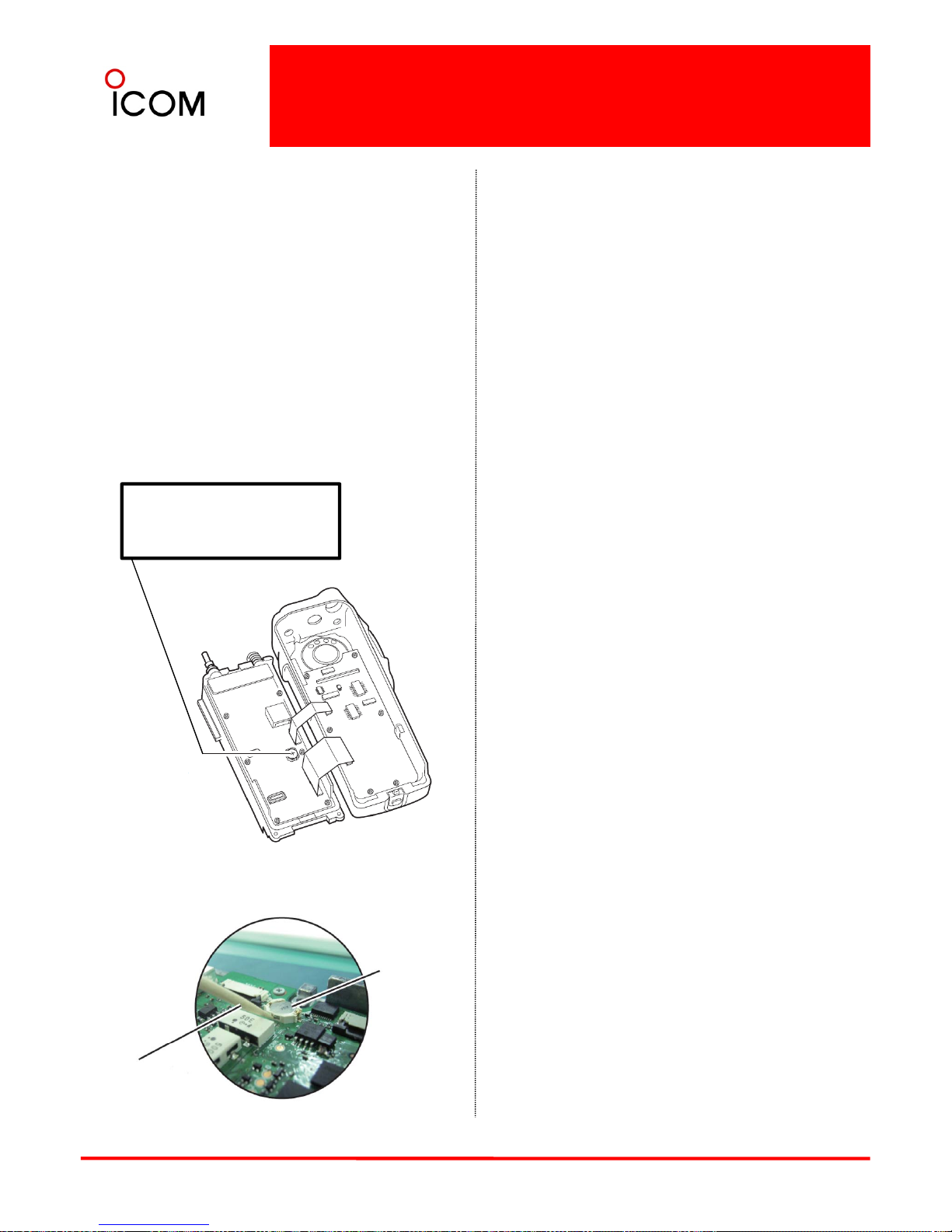
3-3-6 Optional Internal Unit Installation
❑Clock Back-up Battery Replacement
When the backup battery is discharged, the
transceiver transmits and receives normally but
cannot retain the current time.
1Separate the front panel from the CHASSIS.
(Refer to "DISASSEMBLY INSTRUCTION")
2Replace the clock backup battery, located on
the FRONT UNIT as below. (Make sure the battery
polarity is correct.)
3Recover the transceiver, and re-set the date and
time in set mode. (Refer to INSTRUCTION MANUAL)
CLOCK BACKUP BATTERY
MAIN UNIT : “BT1”
Part No. : 3020000340
Part Name : ML-614S/ZT
Battery removal
“+” side is UP
23
Remove old battery
using non-conductive
flat object
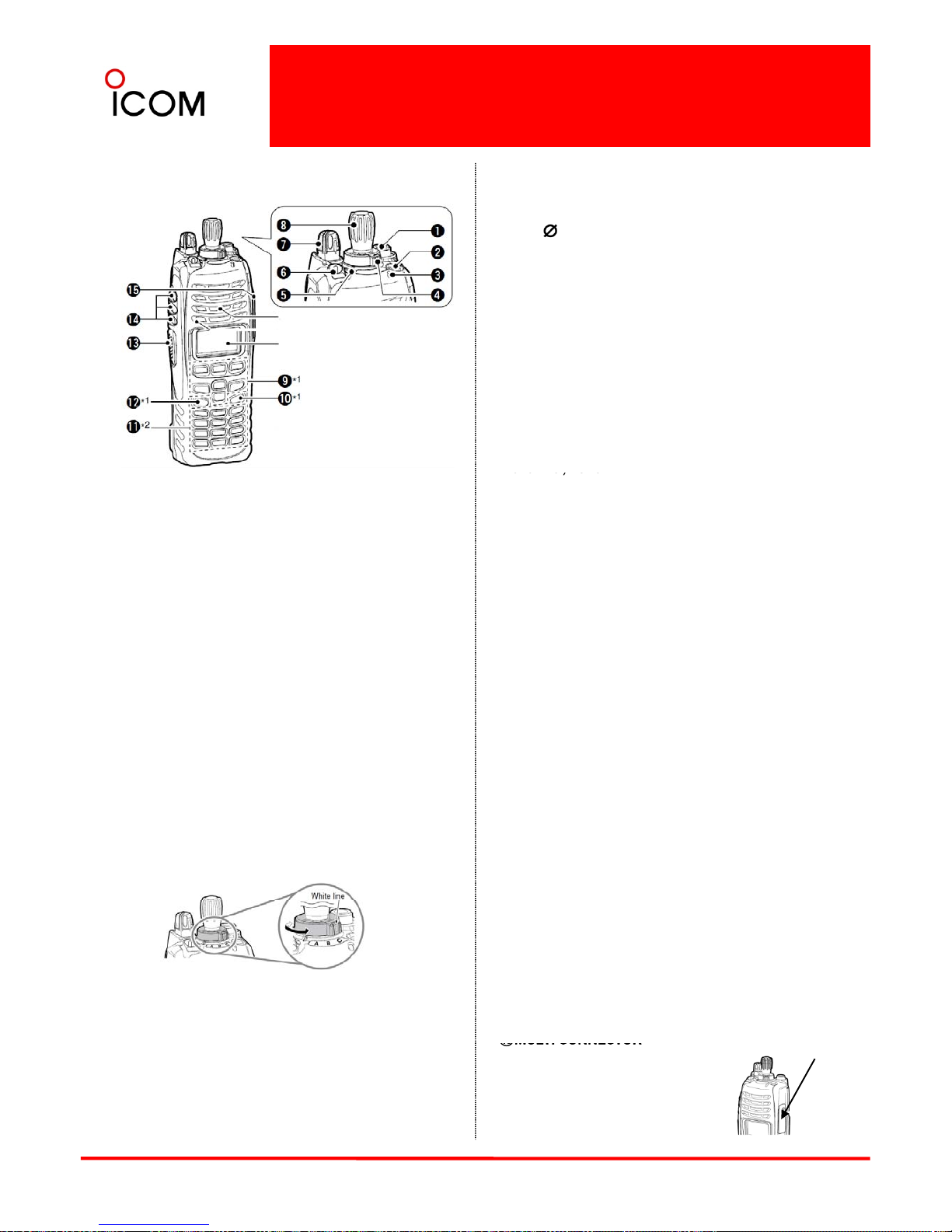
⑥DEALER-PROGRAMMABLE TOGGLE SWITCH
■Front panel
4 Operation and Function
4-1-1 Operation and Function
Desired f
unction can be programme
d by
your
dealer. When the toggle switch is set to the left
side (‘ ’), the preprogrammed function will be
activated.
⑦VOLUME CONTROL [VOL]
Rotate to turn the power ON/OFF and adjusts the
audio level.
Speaker
⑧ROTARY SELECTOR
yRotate to select the pre-programmed memory
channels or the operating zone. (Depending on the
pre-set value)
yThe channel/zone that is positioned to the
channel indicator (⑤) is selected as the operating
channel/zone
.
Mi
crophone
Function Display *1
*1 Simple/10-key types only
*2 10-key type only
①ANTENNA CONNECTOR
Connects the supplied antenna.
②DEALER-PROGRAMMABLE KEY [EMR]
Desired function can be programmed by your
dealer.
ca e/oe
⑨DEALER-PROGRAMMABLE KEYS
[I]/[II]/[III]/[W]/[X]/[S]/[T] (Simple/10-key
models only) Desired function can be programmed
independently by your dealer.
⑩APP KEY [APP] (Simple/10-key models only)
• [Emergency] is pre
programmed as default.
③ LED INDICATOR
➥ Lights green while receiving a signal, or when
the squelch is open.
➥ Lights red while transmitting.
➥ The LED indicator indicates some information.
(Non-display model only)
Desired function can be programmed by your
dealer.
⑪10-KEYPAD (10-key model only)
The keypad allows you to enter digits to:
• Select memory channels, tone channels and
DTMF codes (while in the DTMF code channel
selection mode.)
④DEALER-PROGRAMMABLE ABC SWITCH
Desired functions can be programmed to each
position (A, B or C) independently by your dealer.
To activate the pre-programmed function, set the
white line of the ABC switch to the position A,
B or C.
•
Start up with the
passwor
d
• Input the Individual ID code for digital operation.
(Depending on the pre-set value)
⑫HOME KEY [HOME] (Simple/10-key models only)
Desired function can be programmed by your
dealer. • [Home] is pre-programmed as default.
⑬PTT SWITCH [PTT]
Push and hold to transmit; release to receive.
⑭DEALER-PROGRAMMABLE KEYS
[Side1]/[Side2]/[Side3] Desired function can
be programmed independently by your dealer.
When the white line of the ABC switch is
set to the position C, the pre-programmed
function at position C will be activated.
24
⑮
MULTI
CONNECTOR
Connect optional equipment.
▒ NOTE: Attach the connector
▒ cover when the optional
▒ speaker-microphone is not used.
⑤
CHANNEL INDICATOR
➥ Lights white according to the “Backlight”
setting of the user set mode.
➥ When you rotate [Rotary selector] to select the
channel or zone, align the desired
channel/zone number with this point.
Multi-connector cover
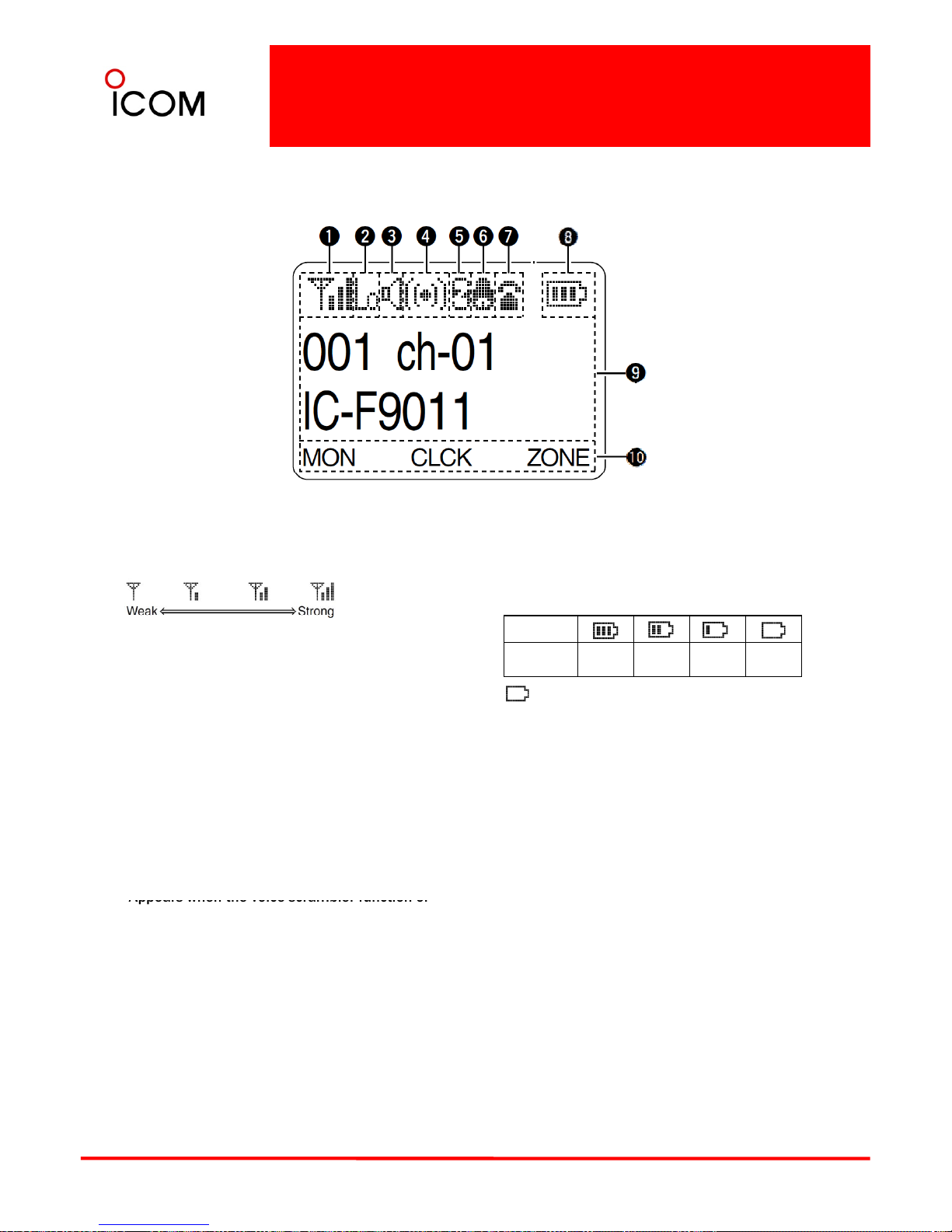
4-1-2 Function Display
[Simple/Full Keypad Models Only]
①SIGNAL STRENGTH INDICATOR
Indicates relative signal strength level.
⑧ BATTERY INDICATOR
Appears or blinks when the battery power
decreases to a specified level.
② LOW POWER INDICATOR
Appears when low output power is selected.
•When high output power is selected, no
indicator appears.
③ AUDIBLE INDICATOR
Appears when the channel is in the ‘audible’
⑨ALPHANUMERIC DISPLAY
Indication
Battery level Full
Partly
charged
Charging
required
No
battery
Blinks when the battery is exhausted.
(unmute) condition.
④ COMPANDER INDICATOR
Appears when the compander function* is
activated.
*Analog mode operation only.
⑤ SCRAMBLER INDICATOR
Displays an operating channel number, channel
name, Set mode contents, DTMF code, etc.
⑩KEY INDICATOR
Indicates the programmed function of the front
panel keys ([I], [II], and [III]).
Appears when the voice scrambler function or
encryption function is activated.
⑥ BELL INDICATOR
Appears/blinks when the specific page call* is
received, according to the pre-programming.
*P25 operation only.
⑦ TELEPHONE INDICATOR
▒ NOTES
▒ See the operating guide for details of Analog
▒ and P25 Trunking/Conventional system
▒ operations. Consult your Icom dealer or system
▒ operator for details concerning your
▒ transceiver’s programming.
25
Appears when a phone call* is received.
*P25 operation only.
▒ Appearance of the icons on the LCD display
▒ depends on the function used and radio
▒ programming.
 Loading...