

Icom IC-F8100 Instruction Manual

INSTRUCTION MANUAL
HF TRANSCEIVER
iF8100
This device complies with Part 15 of the FCC
Rules. Operation is subject to the condition that
this device does not cause harmful interference.
FOREWORD
TABLE OF CONTENTS
Thank you for purchasing this Icom product. The ICF8100 h f t r a n s c e i v e r is designed and built with
Icom’s state of the art technology and craftsmanship.
With proper care, this product should provide you with
years of trouble-free operation.
We appreciate you making the IC-F8100 your radio of
choice, and hope you agree with Icom’s philosophy of
“technology first.”
ment went into the design of your IC-F8100.
Many hours of research and develop-
D FEATURES
❍ ALE (Automatic Link Establishment)/Sel-
call capability
❍ Digital Signal Processor (DSP) allows flex-
ible filter selection
❍ Full-dot matrix LCD for a variety of infor-
mation
IMPORTANT
READ THIS INSTRUCTION MANUAL
CAREFULLY before attempting to operate the
transceiver.
SAVE THIS INSTRUCTION MANUAL. This
manual contains important safety and operating instructions for the IC-F8100.
EXPLICIT DEFINITIONS
WORD DEFINITION
R DANGER!
R WARNING!
CAUTION
NOTE
Personal death, serious injury or an
explosion may occur.
Personal injury, fire hazard or electric
shock may occur.
Equipment damage may occur.
Recommended for optimum use. No
risk of personal injury, fire or electric
shock.
FOREWORD .............................................................. i
IMPORTANT ............................................................... i
EXPLICIT DEFINITIONS ............................................ i
TABLE OF CONTENTS ............................................. i
PRECAUTIONS ......................................................... ii
FCC INFORMATION ................................................ iii
SAFETY TRAINING INFORMATION ....................... iii
INFORMATION EN MATIÈRE DE SÉCURITÉ ........iv
1 PANEL DESCRIPTION ..................................... 1–7
■ Controller (Front panel or HM-192) .................... 1
■ Rear panel ......................................................... 4
■ LCD screen ........................................................ 5
■ AD-119 Optional Junction Box ........................... 7
2 BASIC OPERATION ....................................... 8–11
■ Power ON ..........................................................8
■ Selecting display mode ...................................... 8
■ Selecting a channel ...........................................8
■ Setting audio volume ......................................... 9
■ Squelch function ................................................ 9
■ Scan function ..................................................... 9
■ Mode selection................................................. 10
■ Key Lock function ............................................. 10
■ VFO operation .................................................. 11
3 RECEIVE AND TRANSMIT ...........................12–18
■ Basic voice transmit/receive ............................ 12
■ Functions for transmit ...................................... 13
■ Functions for receive........................................15
4 SELCALL/ALE OPERATION ........................ 19–33
■ Selcall/ALE ......................................................19
5 MENU SCREEN ............................................ 34–46
■ Edit Menu ......................................................... 34
■ User Menu ....................................................... 35
■ Admin Menu ..................................................... 38
■ CPU Reset ....................................................... 46
6 CONNECTION AND INSTALLATION ........... 47–60
■ Supplied accessories ....................................... 47
■ Connections ..................................................... 49
■ Ground connection ..........................................51
■ Power source ................................................... 51
■ Antenna ...........................................................52
■ CFU-F8100 (Optional Cooling Fan) ................. 52
■ RMK-6 (Optional Separation kit) ...................... 53
■ HM-192 (Optional Remote control microphone)
......................................................................... 55
■ Mounting .......................................................... 56
■ Fuse replacement ............................................ 58
■ Connector information for AD-119 ................... 59
7 SPECIFICATIONS ............................................... 61
8 OPTIONS ............................................................62
Icom, Icom Inc. and the Icom logo are registered trademarks
of Icom Incorporated (Japan) in Japan, the United States,
the United Kingdom, Germany, France, Spain, Russia and/or
other countries.
All other products or brands are registered trademarks or
trademarks of their respective holders.
i
Versions of the IC-F8100 which display
the “N33” symbol on the serial number
seal, comply with Standard Australia
Specification No. AS/NZS 4770: 2000.

PRECAUTIONS
R DANGER HIGH RF VOLTAGE! NEVER attach
an antenna or internal antenna connector during transmission. This may result in an electrical shock or burn.
R WARNING! NEVER operate the transceiver with a
headset or other audio accessories at high volume levels.
Hearing experts advise against continuous high volume
operation. If you experience a ringing in your ears, reduce
the volume or discontinue use.
R WARNING! NEVER operate or touch the trans-
ceiver with wet hands. This may result in an electric
shock or damage to the transceiver.
R WARNING! NEVER apply AC power to the
[DC13.8V] socket on the transceiver rear panel. This
could cause a fire or damage the transceiver.
R
WARNING! NEVER apply more than 16 V DC to the
[DC13.8V] socket on the transceiver rear panel, or use reverse
polarity. This could cause a fire or damage the transceiver.
R WARNING!
protrude into the transceiver or into connectors on the
rear panel. This may result in an electric shock.
NEVER let metal, wire or other objects
R WARNING! ALWAYS use the supplied Black and
red cables with fuse holders. After connecting the fuse
holders,
DC plug and fuse holder. If an incorrect connection is
made after cutting, the transceiver might be damaged.
NEVER
cut the DC power cable between the
R WARNING! Immediately turn OFF the transceiver
power and remove the power cable if it emits an abnormal odor, sound or smoke. Contact your Icom dealer or
distributor for advice.
CAUTION: NEVER change the internal settings of the
transceiver. This may reduce transceiver performance
and/or damage to the transceiver.
In particular, incorrect settings for transmitter circuits,
such as output power, idling current, and so on, might
damage the expensive final devices.
The transceiver warranty does not cover any problems
caused by unauthorized internal adjustment.
CAUTION:
without adequate ventilation. Heat dissipation may be
reduced, and the transceiver may be damaged.
NEVER install the transceiver in a place
DO NOT use or place the transceiver in direct sunlight
or in areas with temperatures below –30°C (–22°F) or
above +60°C (+140°F).
The basic operations, transmission and reception of the
transceiver are guaranteed within the specified operating temperature range. However, the LCD display may
not be operate correctly, or show an indication in the
case of long hours of operation, or after being placed in
extremely cold areas.
DO NOT use harsh solvents such as benzine or alco-
hol when cleaning, as they will damage the transceiver
surfaces.
DO NOT push the PTT switch when you don’t actually
desire to transmit.
DO NOT place the transceiver against walls or putting
anything on top of the transceiver. This may overheat
the transceiver.
Always place unit in a secure place to avoid inadvertent
use by children.
BE CAREFUL! If you use a linear amplifier, set the
transceiver’s RF output power to less than the linear
amplifier’s maximum input level, otherwise, the linear
amplifier will be damaged.
BE CAREFUL! The transceiver will become hot when
operating the transceiver continuously for long periods
of time.
USE only the specified microphone. Other manufacturers’ microphones have different pin assignments, and
connection to the IC-F8100 may damage the transceiver
or microphone.
During mobile operation,
where air bag deployment may be obstructed.
During mobile operation,
where hot or cold air blows directly onto it.
During mobile operation,
ceiver without running the vehicle’s engine. When the
transceiver’s power is ON and your vehicle’s engine is
OFF, the vehicle’s battery will soon become exhausted.
Make sure the transceiver power is OFF before starting
the vehicle engine. This will avoid possible damage to the
transceiver by ignition voltage spikes.
During maritime mobile operation, keep the transceiver and microphone as far away as possible from the
magnetic navigation compass to prevent erroneous indications.
Turn OFF the transceiver’s power and/or disconnect the
DC power cable when you will not use the transceiver
for long period of time.
NEVER place the transceiver
DO NOT place the transceiver
DO NOT operate the trans-
KEEP the transceiver away from the heavy rain, and
Never immerse it in the water. The transceiver meets
IP54* requirements for dust-protection and splash resistance.
However, once the transceiver has been dropped, dustprotection and splash resistance cannot be guaranteed
due to the fact that the transceiver may be cracked, or
the waterproof seal damaged, and so on.
* Only when the supplied microphone is attached.
1
2
3
4
5
6
7
8
ii
WARNING
CAUTION
FCC INFORMATION
• FOR CLASS A UNINTENTIONAL RADIATORS:
This equipment has been tested and found to comply with the limits for a Class A digital device, pursuant to part 15
of the FCC Rules. These limits are designed to provide reasonable protection against harmful interference when
the equipment is operated in a commercial environment. This equipment generates, uses, and can radiate radio
frequency energy and, if not installed and used in accordance with the instruction manual, may cause harmful
interference to radio communications. Operation of this equipment in a residential area is likely to cause harmful
interference in which case the user will be required to correct the interference at his own expense.
CAUTION: Changes or modifications to this transceiver, not expressly approved by Icom Inc., could
void your authority to operate this transceiver under
FCC regulations.
SAFETY TRAINING INFORMATION
Your Icom radio generates RF electromagnetic energy during transmit mode. This
radio is designed for and classified as “Occupational Use Only”, meaning it must be
used only during the course of employment
by individuals aware of the hazards, and the ways to
minimize such hazards. This radio is NOT intended for
use by the “General Population” in an uncontrolled environment.
• For compliance with FCC and Industry Canada RF
Exposure Requirements, the transmitter antenna installation shall comply with the following two conditions:
1. The transmitter antenna gain shall not exceed
0 dBi.
2. The antenna is required to be located outside of
a vehicle and kept at a distance of 80 centimeters or more between the transmitting antenna of
this device and any persons during operation. For
small vehicle as worst case, the antenna shall be
located on the roof top at any place on the centre
line along the vehicle in order to achieve 80 centimeters separation distance. In order to ensure
this distance is met, the installation of the antenna
must be mounted at least 80 centimeters away
from the nearest edge of the vehicle in order to
protect against exposure to bystanders.
3.
Transmit only when people outside the vehicle are
at least the recommended minimum distance of
160 centimeters away from the properly installed
antenna. This separation distance will ensure that
there is sufficient distance from a properly installed
externally-mounted antenna to satisfy the RF exposure requirements in the applicable RF exposure
compliance standards.
iii
To ensure that your exposure to RF
electromagnetic energy is within the
FCC allowable limits for occupational
use, always adhere to the following
guidelines:
• DO NOT operate the radio without a proper antenna
attached, as this may damage the radio and may
also cause you to exceed FCC RF exposure limits. A
proper antenna is the antenna supplied with this radio
by the manufacturer or an antenna specifically authorized by the manufacturer for use with this radio.
• DO NOT transmit for more than 50% of total radio use
time (“50% duty cycle”). Transmitting more than 50%
of the time can cause FCC RF exposure compliance
requirements to be exceeded. The radio is transmitting when the “TX” icon is displayed. You can cause
the radio to transmit by pressing the “PTT” switch.
Electromagnetic Interference/Compatibility
During transmissions, your Icom radio generates RF
energy that can possibly cause interference with other
devices or systems. To avoid such interference, turn
OFF the radio in areas where signs are posted to do
so. DO NOT operate the transmitter in areas that are
sensitive to electromagnetic radiation such as hospitals, aircraft, and blasting sites.

INFORMATION EN MATIÈRE DE SÉCURITÉ
AVERTISSEMENT
MISE EN GARDE
Votre radio Icom produit une énergie
électromagnétique de radiofréquences (RF), en mode de transmission.
Cette ra dio est conçue pour un
«usage professionnel seulement» et
classée comme tel, ce qui signifie qu’elle doit être
utilisée uniquement dans le cadre d’un travail par
des personnes conscientes des dangers et des
mesures visant à minimiser ces dangers. Elle
N’EST PAS conçue pour une «utilisation grand
public», dans un environnement non contrôlé.
• Afin de satisfaire aux exigences de la FCC et d’In-
dustrie Canada en matière d’exposition aux RF, il
est nécessaire que l’antenne soit installée conformément aux trois conditions suivantes:
1. Le gain de l’antenne du radio émetteur ne doit
pas dépasser 0dBi.
2. Il faut que l’antenne émettrice de cet appareil
soit placée à l’extérieur d’un véhicule et tenue
éloignée d’au moins 80 centimètres de toute personne pendant le fonctionnement. Dans le pire
des cas, pour un petit véhicule, l’antenne doit être
placée sur le toit, n’importe où dans l’axe central
du véhicule, afin de respecter une distance de 80
cm du bord le plus rapproché du véhicule et ainsi
éviter que les personnes présentes soient exposées.
3. Émettre uniquement lorsque les personnes à
l’extérieur du véhicule se trouvent à au moins la
distance minimale recommandée de 160 cm de
l’antenne correctement installée. Cette distance
de sécurité assurera que les personnes soient
placées suffisamment loin d’une antenne correctement fixée à l’extérieur pour satisfaire aux exigences en matière d’exposition aux RF, en vertu des
normes de conformité applicables.
Afin de vous assurer que votre exposition à une énergie électromagnétique de RF se situe dans les limites
permises par la FCC pour une utilisation grand public, veuillez en tout
temps respecter les directives suivantes:
• NE PAS faire fonctionner la radio sans qu’une
antenne appropriée y soit fixée, car ceci risque
d’endommager la radio et causer une exposition
supérieure aux limites établies par la FCC. L’antenne appropriée est celle qui est fournie avec
cette radio par le fabricant ou une antenne spécialement autorisée par le fabricant pour être utilisée
avec cette radio.
• NE PAS émettre pendant plus de 50 % du temps
total d’utilisation de l’appareil («50 % du facteur
d’utilisation»). Émettre pendant plus de 50 % du
temps total d’utilisation peut causer une exposition aux RF supérieure aux limites établies par
la FCC. La radio est en train d’émettre lorsque
le témoin du mode de transmission s’affiche sur
l’écran ACL. La radio émettra si vous appuyez sur
le bouton du microphone.
Interférence électromagnétique et compatibilité
En mode de transmission, votre radio Icom produit de
l’énergie de RF qui peut provoquer des interférences
avec d’autres appareils ou systèmes. Pour éviter de
telles interférences, mettez la radio hors tension dans
les secteurs où une signalisation l’exige. NE PAS faire
fonctionner l’émetteur dans des secteurs sensibles
au rayonnement électromagnétique tels que les hôpitaux, les aéronefs et les sites de dynamitage.
iv
1
q w
w !1e
er
io!0
tyu
Keypad (p. 2)
q
o
u
y
t
r
i
• HM-192
• Front panel
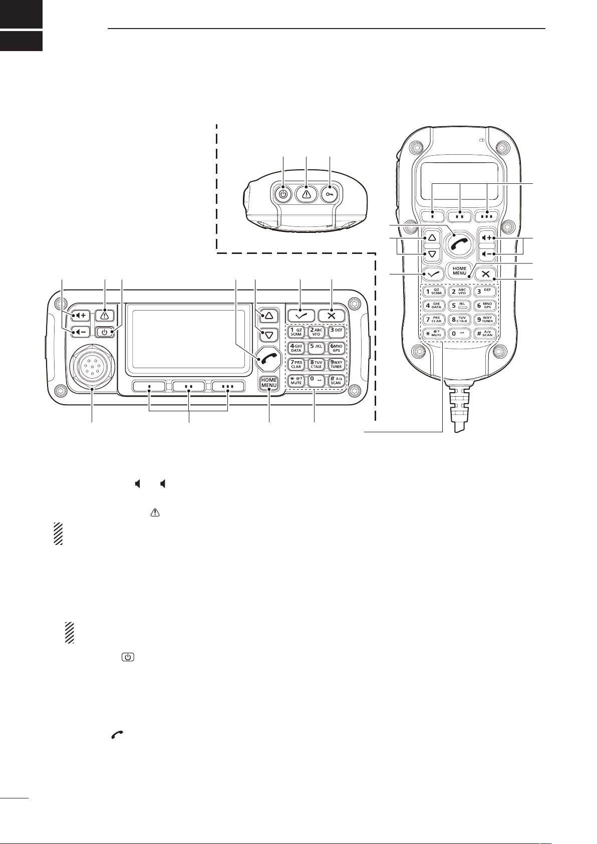
PANEL DESCRIPTION
■ Controller (Front panel or HM-192)
• Common
q VOLUME KEYS [ +]/[ –] (p. 9)
Adjusts the audio output level.
w EMERGENCY KEY [
NOTE: While in the VFO mode, the Emergency
➥ Push to enter the Emergency channel list.
• Push again to return to the normal operating screen.
➥ Hold down for 1 second to transmit the Selcall
NOTE: RFDS calls are available in only the
e POWER KEY [
➥ When the transceiver’s power is OFF:
Push to turn ON the transceiver power.
• First, turn ON the DC power source.
➥ When the transceiver’s power is ON:
r CALL KEY [ ]
Push to enter the Call menu.
• Push again to go to the next screen in the Call menu.
]
key cannot be used.
and RFDS (Royal Flying Doctor Service) calls
to the specified Selcall addresses in sequential
order.
AUS versions.
]
Hold down for 2 seconds to turn OFF the power.
t UP/DOWN KEYS [r]/[s]
Selects the operating channel, the items in the
Menu mode, and so on.
y ENTER KEY [4]
Push to enter or exit the selected Menu in the Menu
screen.
u CLEAR KEY [8]
➥ Push to exit the Menu screen.
➥ Push to return to the previous screen in the Call
menu.
i HOME/MENU KEY [HOME] [MENU](HOME)
➥ Push to return to the home display.
➥ Hold down for 1 second to enter the Menu
o FUNCTION KEYS [§]/[§§]/[§§§]
Push to select the function that is displayed above
• The functions vary, depending on the selected menu and
screen.
each key on the LCD display.
the operating mode.
1
y
u
t
r
q
w
e
i
Front view
10-key
• Front panel • HM-192
KEY INPUT INPUTKEY
(space)
Upper/Lower case letters/Numbers
1 Q Z q z
2 A B C a b c
3 D E F d e f
4 G H I g h i
5 J K L j k l
6 M N O m n o
7 P R S p r s
8 T U V t u v
9 W X Y w x y
0
, . ; ? : ” ` ’ / ! @ # $ % ^ &
* ( ) _ – + = | \
~
< > { } [ ]
!0 MICROPHONE CONNECTOR [MIC]
Connects to only the microphone supplied with the
transceiver.
NOTE: NEVER connect the HM-192 or any other
microphone here. This could damage the transceiver and/or the microphone.
!1 LOCK KEY [
Hold down for 1 second to set the Key lock function
to ALL, NUMERIC KEY or OFF.
PANEL DESCRIPTION
]
1
q MIC (microphone input)
w MIC SW1
e AF
r MIC SW2
t PTT
y GND
u GND (microphone ground)
i +8 V DC output (Max 10 mA)
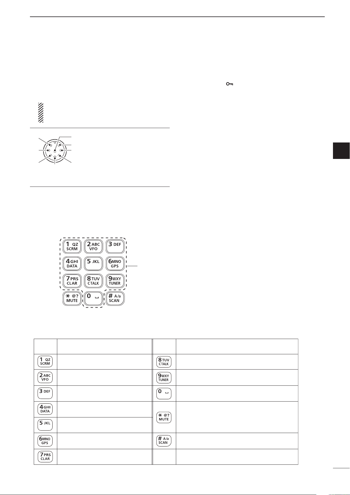
D Keypad
➥ Inputs numbers for the Clock Setting.
➥ Inputs numbers, characters or letters for the Sel-
call direct input.
Quick Reference
1
2
3
4
5
6
7
8
9
• Selectable characters
10
11
12
13
14
15
16
17
2

1
PANEL DESCRIPTION
Keypad (Continued) D
VFO KEY [VFO]
Push to turn the VFO mode ON or OFF.
NOTE: The VFO mode operation can be
inhibited in the Admin Menu. (p. 39)
GPS KEY [GPS]
When a GPS receiver is connected through
the optional AD-119 Junction Box or OPC2205 Shielded control cable, and valid data
is received, push to turn the GPS display ON
or OFF. The GPS information that can be selected are Position, Direction and Elevation.
CLARIFIER KEY [CLAR]
Push to turn the Clarifier function ON or
OFF.
NOTE: This key cannot be used when the
“Clarifier” item in the User Menu is set to
“OFF.” (p. 36)
CLEAR TALK KEY [C TALK]
Push to turn the Clear Talk function ON or
OFF.
• The “C” icon appears when the function is ON.
TUNER KEY [TUNER]
Push to turn the Antenna tune mode to Auto,
Manual or OFF. (p. 12)
• The “Auto Tune” or “Manual Tune” screen appears when the antenna tune mode is ON.
• The SWR meter appears when the antenna tune
mode is ON.
MUTE KEY [MUTE]
Push to select the squelch type. Call squelch,
S-meter squelch (level 1 to 50), Voice squelch
or squelch OFF are selectable.
• The “S” icon appears when the Call squelch
function is ON.
• The “L” icon appears when the S-meter squelch
function is ON.
• The “V” icon appears when the Voice squelch
function is ON.
SCAN KEY [SCAN]
Push to start or stop a scan.
3
ACC2
ACC1
GND
ANT
y
t
r
u
DC
q
FAN
Protect plug
w
SP
e
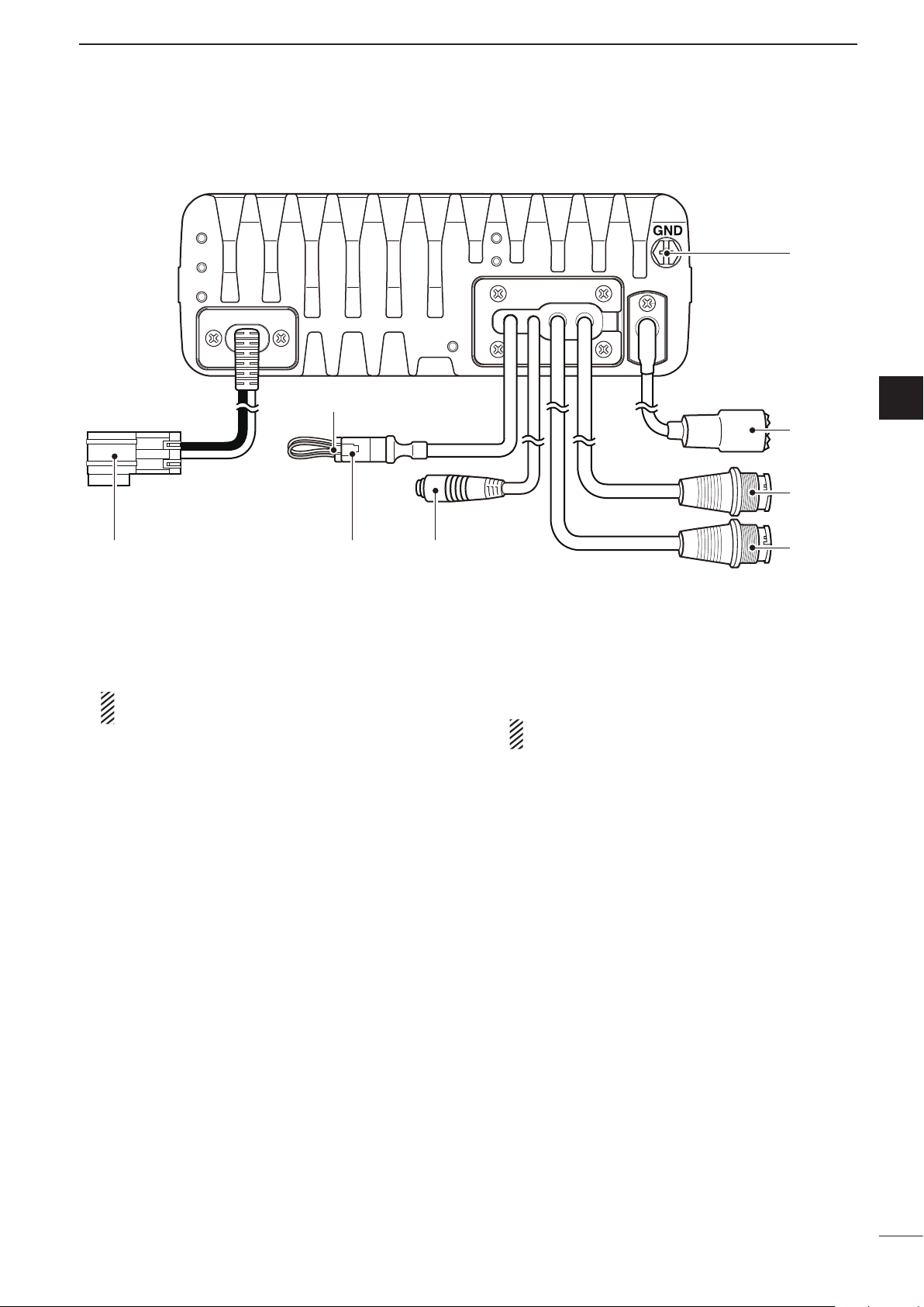
■ Rear panel
PANEL DESCRIPTION
1
Quick Reference
1
2
3
q DC POWER CONNECTOR [DC]
Accepts 13.8 V DC through a DC power cable.
w FAN CONNECTOR [FAN]
Connects to the optional CFU-F8100 Cooling Fan.
NOTE: Attach the protect plug when the optional
Cooling Fan is not used.
e SPEAKER JACK [SP]
Connects to an external speaker such as the sup-
plied SP-25.
r ACCESSORY CONNECTOR (10 PIN) [ACC1]
t ACCESSORY CONNECTOR (12 PIN) [ACC2]
Connects to the optional AD-119
OPC-2205 s h i e l d e d c o n t r o l c a b l e .
Both connectors must be connected to use the AD-
119 or OPC-2205.
NOTE: Attach the connector caps when the op-
tional unit or cable is not used.
y ANTENNA CONNECTOR
Connects to a 50 Ω HF band antenna.
u GROUND TERMINAL
IMPORTANT! Connects to a solid ground point.
j u n c t i o n b o x or
4
5
6
7
8
9
10
11
12
13
14
15
16
17
4
1
:
:
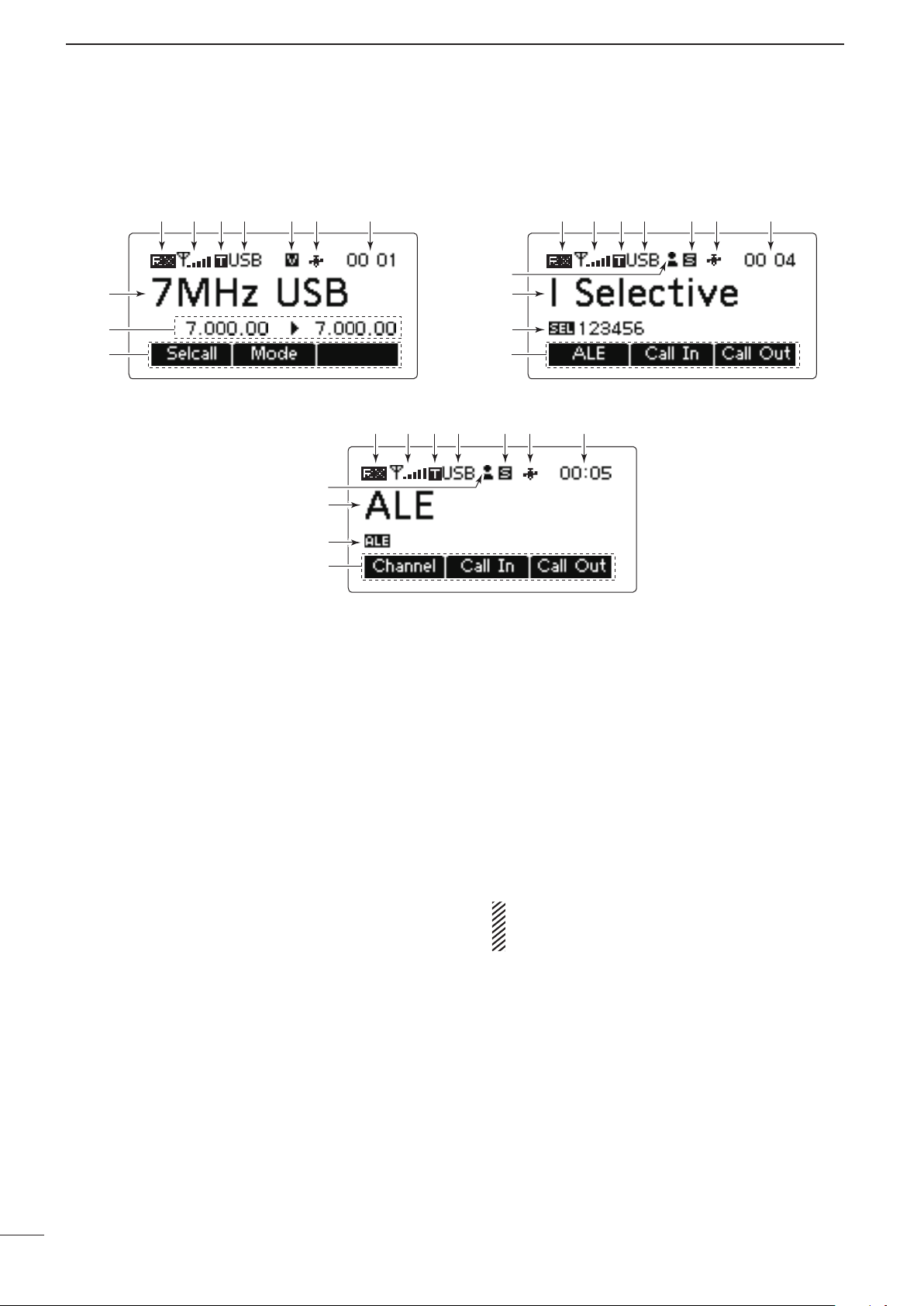
• Memory Channel Display • Selcall Address Display
• ALE ID Display
q w r t y u q w r t y u
q w r
e e
e t y u
o
!0
o
!0
!1
!1
o
!0
i i
i
PANEL DESCRIPTION
■ LCD screen
q RECEIVE/TRANSMIT ICON
➥ “ RX” appears when signals are received or the
squelch is open.
➥ “ TX” appears during transmit.
w S-METER/TX METERS
➥ Displays the receive signal strength.
➥ Displays the transmit output power.
Mic gain can also be displayed when the “METER
TYPE” item in the Admin Menu is set to “MIC
LEVEL.”
e TUNE ICON
Appears after the automatic antenna tuner matches
the transceiver and antenna.
r OPERATING MODE INDICATOR
Displays the selected operating mode.
• “LSB,” “USB,” “CW,” “AM,” “D1,”* “D2”* or “D3”* appears,
depending on the operating mode.
* When the “Modem” setting in the Admin Menu is set to
“OFF,” “RTTY” appears instead. (p. 40)
The D1, D2 or D3 mode can be set in the “Data mode
1,” “Data mode 2” or “Data mode 3” settings in the
Admin Menu. (p. 40)
t MUTE ICON
➥ “S” appears when the Call squelch function is se-
➥ “L” appears when the S-meter squelch is se-
➥ “V” appears when the Voice squelch is selected.
lected.
lected.
y GPS ICON
Appears when valid position data is received from
a GPS receiver that is connected to the AD-119 or
OPC-2205.
u TIME DISPLAY
Displays the time.
i FUNCTION DISPLAY
Displays the function of the [§], [§§] and [§§§] func-
tion keys.
o SUB READOUTS
<Memory Channel display>
Shows the channel transmit and receive frequen-
cies. The receive frequency is displayed on the right
and the transmit frequency is displayed on the left.
NOTE: The transmit frequency is not displayed
when the selected channel is configured as “receive only.”
<Selcall Address display>
Shows the Selcall ID or phone number of the call.
<ALE ID display>
Displays the NET ID for ALE transmissions.
!0 MAIN READOUTS
<Memory Channel display>
Displays the channel name.
<Selcall Address display>
Shows the Selcall Address of the call.
<ALE ID display>
Shows the ALE ID for ALE transmission.
5

PANEL DESCRIPTION
:
:
• Memory Channel Display • Selcall Address Display
• ALE ID Display
q w r t y u q w r t y u
q w r
e e
e t y u
o
!0
o
!0
!1
!1
o
!0
i i
i
1
Quick Reference
1
2
3
!1 CALL ICON
Displays the Call type icons for Selcall.
• The “ ” icon appears when a Selective call address
name is selected on the Selcall Address display.
• The “
name is selected on the Selcall Address display.
• The “
name is selected on the Selcall Address display.
• The “
address name is selected on the Selcall Address display.
• The “
address name is selected on the Selcall Address display.
• The “
name is selected on the Selcall Address display.
• The “
address name is selected on the Selcall Address display.
• The “
dress name is selected on the Selcall Address display.
• The “
dress name is selected on the Selcall Address display.
” icon appears when a Phone call address
” icon appears when a Message call address
” icon appears when a GPS Send Position call
” icon appears when a GPS Get Position call
” icon appears when a Get Status call address
” icon appears when an RFDS Emergency call
” icon appears when an Emergency call ad-
” icon appears when a Channel Test call ad-
4
5
6
7
8
9
10
11
12
13
14
15
16
17
6

1
q w e
q
t
w e r
PANEL DESCRIPTION
■ AD-119 Optional Junction Box
D Front Panel
q DATA JACK [DATA]
Connects to a PC through an RS-232C cable (D-
sub 9-pin) for remote control in the RS-232C format.
w GPS CONNECTOR [GPS]
Connects to a GPS receiver to automatically set
your position and time data in NMEA0183 ver. 2.0
or 3.01 formats.
e GPIO CONNECTOR [GPIO]
Connects to the control cable of the optional AT-
140 Antenna Tuner or AT230 Automatic Tuning Antenna.
D Rear Panel
q USB CONNECTOR [USB]
Connects to a PC through an A-B type USB cable.
w ACCESSORY CONNECTOR 2 (12 PIN) [ACC2]
e ACCESSORY CONNECTOR 1 (10 PIN) [ACC1]
Connects to the IC-F8100’s Accessory connectors.
Both connectors must be connected to use this
Junction Box.
r
GROUND TERMINAL
IMPORTANT! Connects to a solid ground point.
EXTERNAL MODEM CONNECTOR [EXT. MODEM]
t
Connects to an external unit such as an HF email
modem or TNC (Terminal Node Controller).
NOTE: This connector may not be available, de-
pending on the AD-119’s version.
7

■ Power ON
Memory channel display
Selcall Address display
ALE ID display
➥ Push [ ] to turn ON the Power.
• Built-in Test is displayed.
The BIT display can be turned OFF in the Advance
Menu.
• Hold down [
] for 2 seconds to turn OFF the power.
■ Selecting display mode
➥ Push [§] one or more times to select a desired dis-
play mode.
• The display sequentially selects “Channel” ➪ “Selcall”
➪“ALE” ➪“Channel.”
BASIC OPERATION
2
Quick Reference
1
2
3
4
■ Selecting a channel
q Push [§] one or more times to select the Memory
Channel display.
• The display sequentially selects “Channel” ➪ “Selcall”
➪“ALE” ➪“Channel.”
w Push [r] or [s] to select a desired memory chan-
nel.
5
6
7
8
9
10
11
12
13
14
•
•
•
15
16
17
8
2
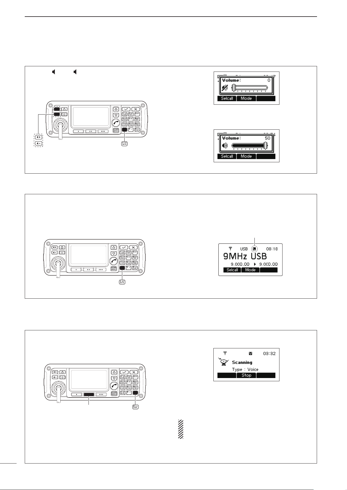
Mute icon
[Stop]
BASIC OPERATION
■ Setting audio volume
➥ Push [ +] or [ –] to adjust the audio level.
• If the squelch is closed, push [MUTE](M) one or more
times to open the squelch.
• The display shows the volume level while adjusting.
■ Squelch function
The squelch function detects signals with voice components and squelches (mutes) unwanted signals.
This provides quiet stand-by.
When you need to receive weak signals, the squelch
can be turned OFF.
Minimum audio level
Maximum audio level
➥ Push [MUTE](M) one or more times to select a
squelch type. Selectable types are Call SQL, Smeter SQL (level 1 to 50), Voice SQL and OFF.
• The S-meter squelch level can be adjusted in “Squelch
Level” in the User Menu
•
•
•
.
■ Scan function
The scan function repeatedly scans programmed
channels. This function is convenient to wait for calls
on multiple channels.
• The Mute icon, “S,” “L” or “V,” appears when the
squelch function is turned ON.
q Push [SCAN](#) to start a scan.
• “Scanning” and the Scan type are displayed.
w When a signal is received, the scan pauses on
that channel.
e Push [Stop](§§) to cancel the scan.
• Pushing [SCAN](#) also cancels the scan.
NOTE: The scan resume setting (the action after
receiving a signal) can be changed in “Scan Resume” in the Admin Menu. (p. 41)
9

[Mode]
[Default] [][]
/
■ Mode selection
BASIC OPERATION
2
The following modes are selectable in the IC-F8100:
LSB, USB, CW, AM, D1,* D2* and D3.*
* When the “Modem” setting in the Admin Menu is set to
“OFF,” “RTTY” can be selected instead. (p. 40)
The D1, D2 or D3 mode can be set in the “Data mode
1,” “Data mode 2” or “Data mode 3” settings in the Admin
Menu. (p. 40)
■ Key Lock function
q Push [§] one or more times to select the Memory
Channel display.
• The display sequentially selects “Channel” ➪ “Selcall”
➪“ALE” ➪“Channel.”
w Push [Mode](§§) one or more times to select the
desired mode.
• The selected mode icon appears at the top of the display.
NOTE:
• The selected mode can be used only temporarily.
When the channel is changed, it returns to the
preprogrammed operating mode.
• Depending on the transceiver version or preprogramming, some operating modes may not be
selectable or usable except receive.
Quick Reference
1
2
3
4
5
6
To prevent accidental channel changes, or unnecessary function access, use the Key Lock function. The
transceiver has two types of Key Lock functions.
q Hold down [MENU](HOME) for 1 second to enter
the Menu screen.
w Push [r] or [s] to select the “User Menu,” and
then push [4].
e Push [r] or [s] to select “Key Lock.”
r Push [t ](§) or [u](§§§) to select the Key Lock
function, “ALL” or “NUMERIC KEY.”
• Hold down [Default](§§) for 1 second to return to the
default setting
t Push [MENU](HOME) twice to return to the nor-
mal operating screen.
• To turn OFF the function
When you push the locked key, “Numeric Key Locked”
or “All Key Locked” appears, depending on the function. Then push [Unlock](§§) to turn OFF the function.
.
7
8
9
10
11
12
13
14
15
16
17
10
2
[��][���][�]
/
BASIC OPERATION
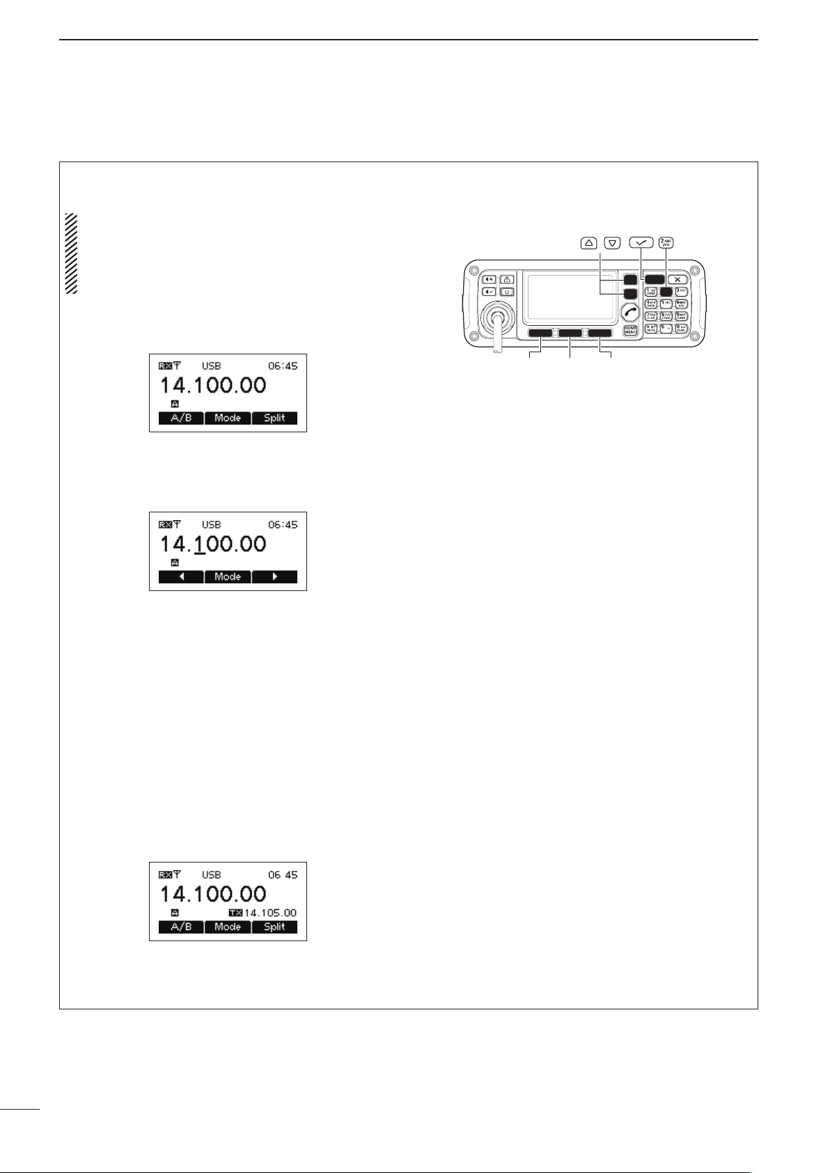
■ VFO operation
In the VFO mode, you can set a desired operating frequency, operating mode or split frequency function.
NOTE:
• The VFO mode operation can be disabled in the
Admin Menu.
• While in the VFO mode, the Selcall, ALE features
or the Emergency key cannot be used.
• Entering the VFO mode
Push [VFO](2) to turn the VFO mode ON or OFF.
• Frequency setting
q Push [A/B](§) to select VFO A or VFO B.
w Push [4] to enter the frequency setting mode.
e Push [t](§) or [u](§§§) to move the cursor to se-
lect the desired digit to change.
• The cursor is displayed below the selected digit
r Push [r] or [s] to change the frequency.
t Push [4] to exit the frequency setting mode.
• Turning ON the split frequency function
q Push [A/B](§) to select VFO A or VFO B, and
separately set the receive and transmit frequencies.
w Push [Split](§§§) to turn the split frequency func-
tion ON.
• The TX frequency appears below the RX frequency
• Pushing [A/B](§) changes the VFOs between trans-
mit and receive.
e To turn OFF the split frequency function, push
[Split](§§§) again.
.
.
11
RECEIVE AND TRANSMIT
Mute icon
■ Basic voice transmit/receive
3
q First, check the following.
➥ The microphone and external speaker are con-
nected.
➥ No “S,” “ L” or “V” mute icon appears.
• If “S,” “ L” or “V” appears, push [MUTE](M) one or
more times to turn OFF the mute.
w Push [r
nel.
•
The S-meter shows signal strength when signal is received.
e Push [ +] or [ –] to adjust a desired audio level
when receiving a signal.
• If the bass or treble of the receive audio is too strong,
set “Clarifier” to ON in the User Menu, and adjust to obtain clear audio. (See page 15 for the Clarifier function
details.)
• If the audio is distorted, select the suitable operating
mode. (See page 10 for the Mode selection details.)
] or [s] to select the desired receive chan-
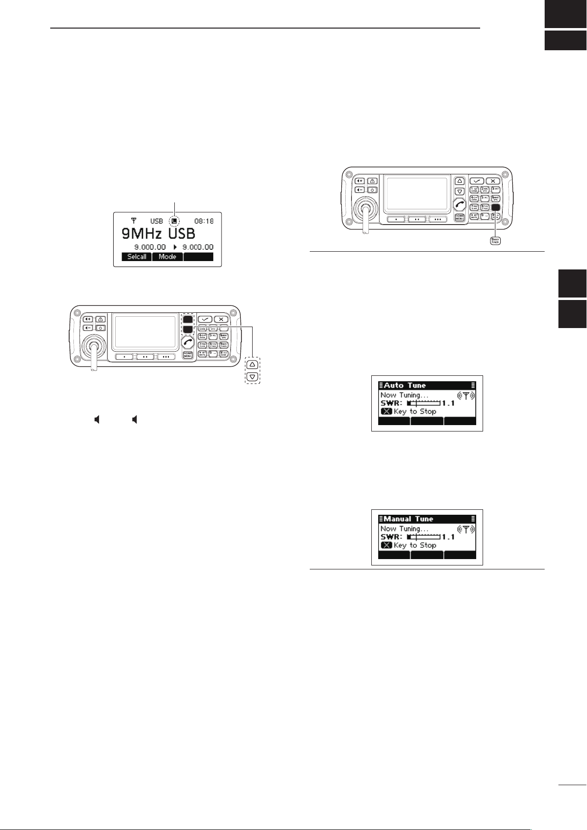
r Push [TUNER](9) once or twice to enter the an-
tenna tune mode.
• The “Auto Tune” or “Manual Tune” screen sequentially
appears.
When the transceiver is connected to an optional
antenna tuner and “Auto Tune” screen is selected,
push [4] to start auto tuning.
• The display shows the antenna SWR.
• If the antenna cannot be tuned after 20 seconds, the
tuning circuit is automatically bypassed.
• After tuning is finished, the auto tune automatically
stops transmitting.
• Push [8] to manually stop transmitting, if necessary.
• Push [Through](§§) to turn OFF the AT-140 (bypass).
When the transceiver is connected to another an-
tenna tuner, or directly connected to an antenna
and the “Manual Tune” screen is selected, push [4]
to start transmitting and tune the antenna.
• The display shows the antenna SWR.
• Push [8] to stop transmitting.
Quick Reference
1
2
3
4
5
6
7
8
9
t After tuning is finished, push [TUNER](9) once or
twice to return to the normal operating screen.
y To transmit on the channel, hold down [PTT] on the
microphone, and speak at a normal voice level.
• The RF meter shows the output power.
u Release [PTT] to receive.
10
11
12
13
14
15
16
17
12
[Default] [][]
/
[Default] [][]
/
3
RECEIVE AND TRANSMIT
■ Functions for transmit
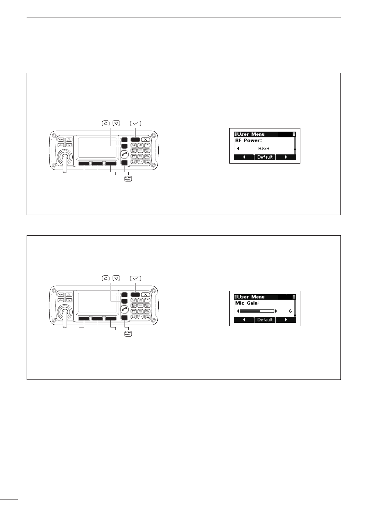
ï Transmit power selection
The transceiver has three output power levels, HIGH,
MID and LOW. High power provides longer distance
communications and low power reduces power consumption.
ï Setting Microphone gain
The microphone gain must be properly adjusted so
that your signal is not distorted when transmitted.
q Hold down [MENU](HOME) for 1 second to enter
the Menu screen.
w Push [r] or [s] to select the “User Menu,” and
then push [4].
e Push [r] or [s] to select “RF Power.”
r Push [t](§) or [u](§§§) to select the desired out-
put power.
• Hold down [Default](§§) for 1 second to return to the
default setting
t Push [MENU](HOME) twice to return to the nor-
mal operating screen.
q Hold down [MENU](HOME) for 1 second to enter
the Menu screen.
w Push [r] or [s] to select the “User Menu,” and
then push [4].
e Push [r] or [s] to select “Mic Gain.”
.
13
r Push [t](§) or [u](§§§) to select the desired Mic
gain.
• Hold down [Default](§§) for 1 second to return to the
default setting
t Push [MENU](HOME) twice to return to the nor-
mal operating screen.
.
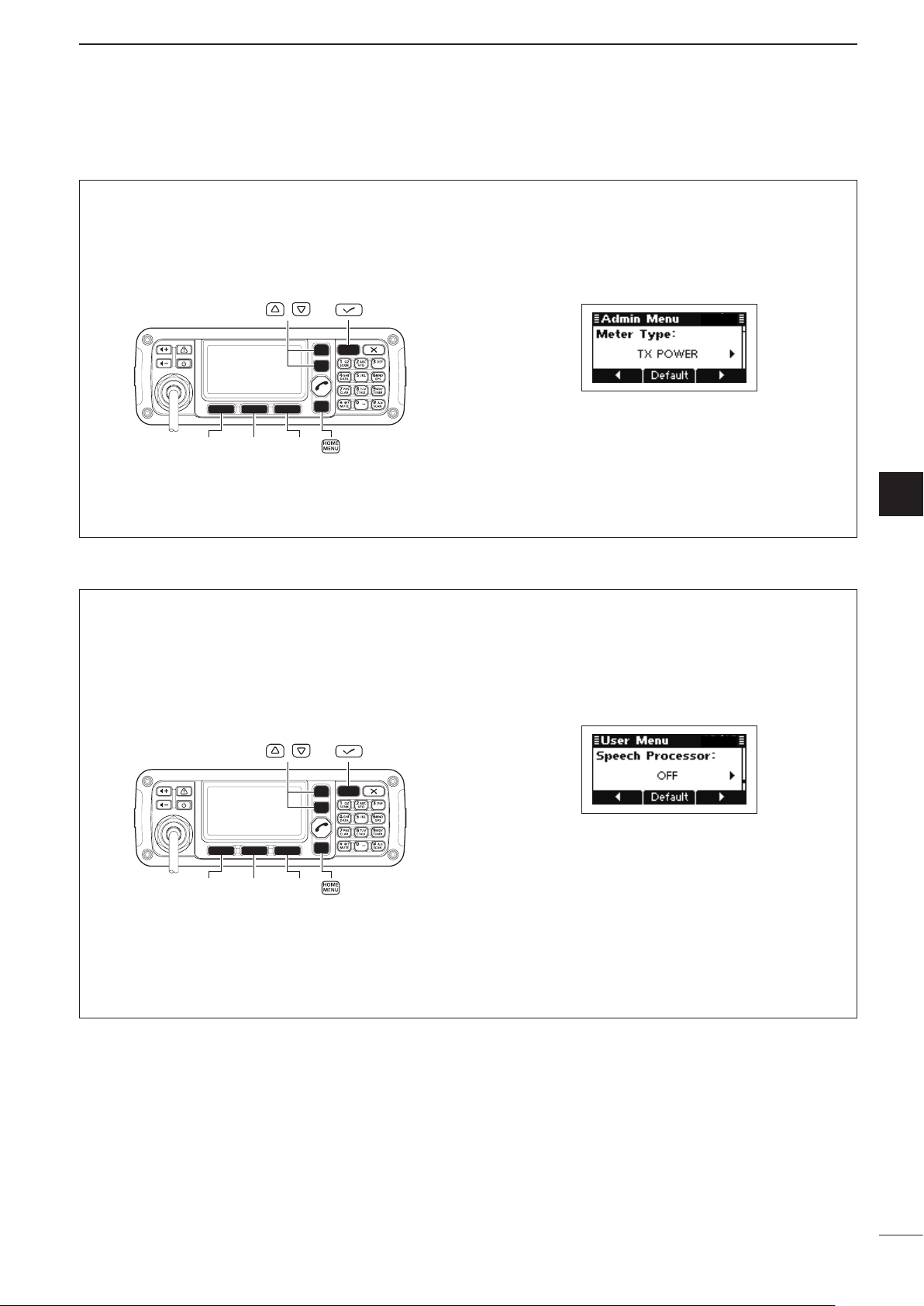
ï Checking the MIC level
[Default] [][]
/
[Default] [][]
/
The transceiver has a MIC level meter. You can check
the MIC level before or after adjusting the Microphone
gain.
RECEIVE AND TRANSMIT
q Hold down [MENU](HOME) for 1 second to enter
the Menu screen.
w Push [r] or [s] to select the “Admin Menu,” and
then push [4].
e Push [r] or [s] to select “Meter Type.”
r Push [u](§§§) to select “MIC LEVEL.”
t Push [MENU](HOME) twice to return to the nor-
mal operating screen.
y Hold down [PTT] on the microphone, and speak at
a normal voice level.
u While speaking into the microphone, check the TX
meter reading.
3
3
ï Speech Processor
The IC-F8100 has a built-in, low distortion Speech
Processor circuit. This circuit increases your average
talk power in the SSB mode and is especially useful
when the receiving station is having difficulty hearing
your audio.
q Hold down [MENU](HOME) for 1 second to enter
the Menu screen.
w Push [r] or [s] to select the “User Menu,” and
then push [4].
e Push [r] or [s] to select “Speech Processor.”
r Push [t](§) or [u](§§§) to turn the Speech proces-
sor function ON or OFF.
• Hold down [Default](§§) for 1 second to return to the
default setting
t Push [MENU](HOME) twice to return to the nor-
mal operating screen.
y Push [Mode](§§) one or more times to select the
USB or LSB mode.
u Hold down [PTT] on the microphone, and speak at
a normal voice level.
.
14
3
[�]
/
[��][���][�]
/
Upper shiftLower shift
RECEIVE AND TRANSMIT
■ Functions for receive
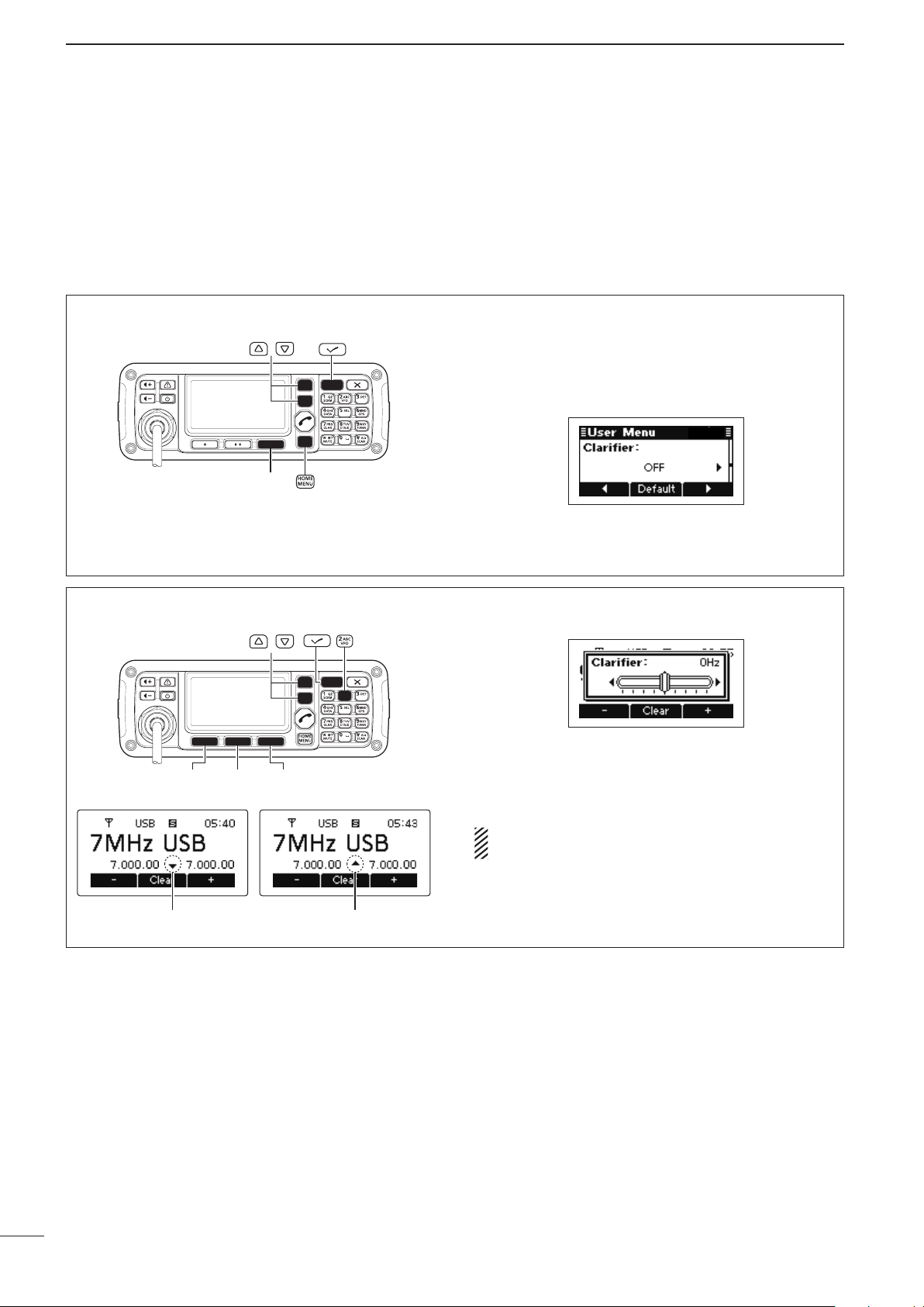
ï Clarifier function
The Clarifier function compensates for off-frequency
stations. The function shifts the receive frequency up
to ±200 Hz, without shifting the transmit frequency.
• Setting
q Hold down [MENU](HOME) for 1 second to enter
the Menu screen.
w Push [r] or [s] to select the “User Menu,” and
then push [4].
e Push [r] or [s] to select “Clarifier.”
r Push [u](§§§) to turn ON the Clarifier function.
t Push [MENU](HOME) twice to return to the nor-
mal operating screen.
• Operation
q Push [CLAR](7) to turn ON the Clarifier function.
w Push [–](§) or [+](§§§) to tune the frequency shift.
• The transmit frequency is not shifted.
• Hold down [Clear](§§) for 1 second to return to the
center position, if desired.
When cancelling the Clarifier function, push
[CLAR](7) again.
15
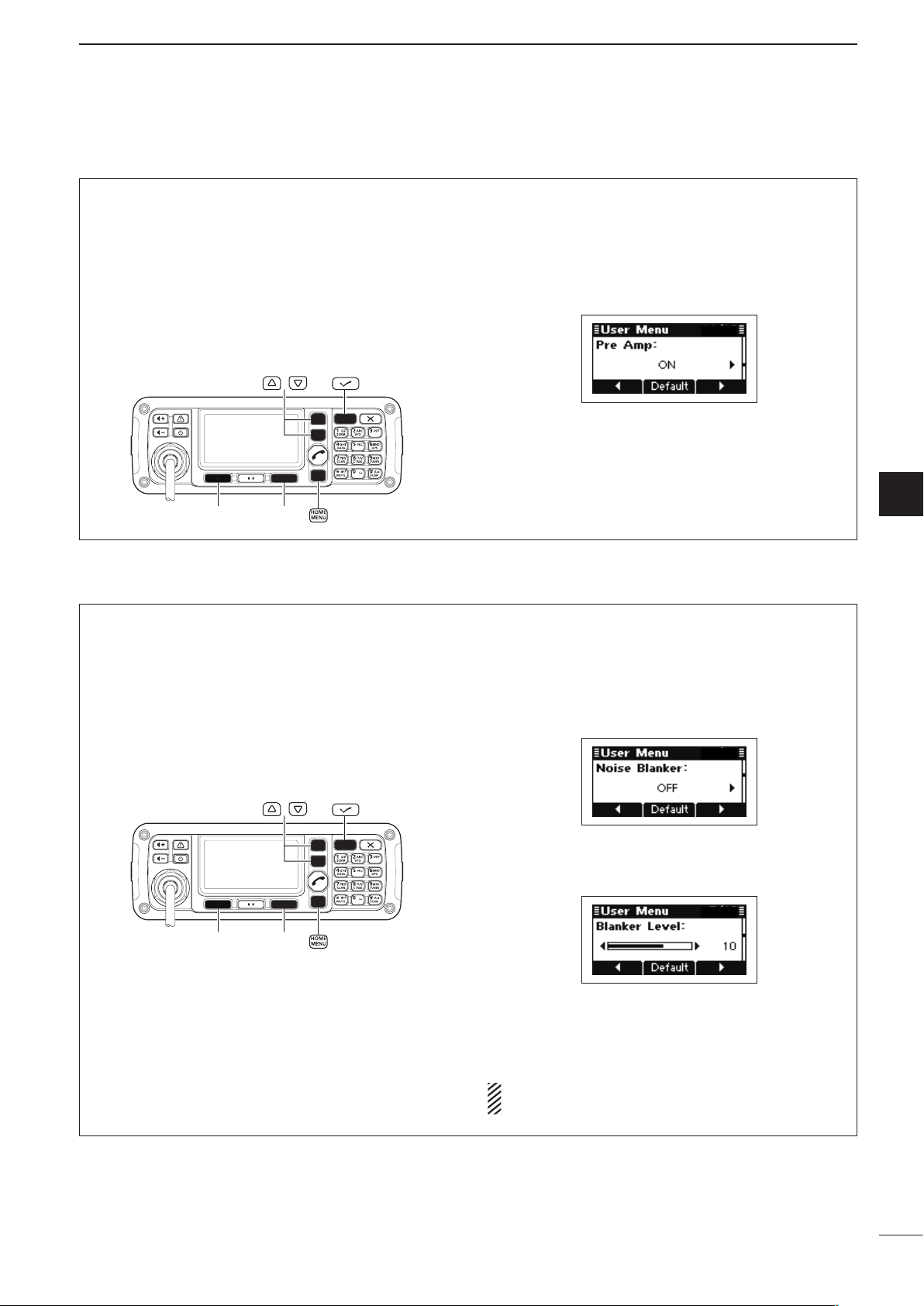
ï Preamp and Attenuator
[][]
/
[][]
/
RECEIVE AND TRANSMIT
3
The preamp amplifies received signals in the front
end circuit to improve the S/N ratio and sensitivity.
Turn ON this function to better receive weak signals.
The attenuator prevents strong undesired signals
near the desired frequency or near your location,
such as from a broadcast station, from causing distortion or spurious signals.
ï Noise Blanker
The noise blanker reduces pulse-type noise such as
that generated by automobile ignition systems.
The noise blanker may distort reception of strong
signals. In such cases, the noise blanker should be
turned OFF.
q Hold down [MENU](HOME) for 1 second to enter
the Menu screen.
w Push [r] or [s] to select the “User Menu,” and
then push [4].
e Push [r] or [s] to select “Pre Amp.”
r Push [t](§) or [u](§§§) to turn ON the Preamp or
Attenuator function.
t Push [MENU](HOME) twice to return to the nor-
mal operating screen.
3
q Hold down [MENU](HOME) for 1 second to enter
the Menu screen.
w Push [r] or [s] to select the “User Menu,” and
then push [4].
e Push [r] or [s] to select “Noise Blanker.”
r Push [u](§§§) to turn ON the Noise Blanker func-
tion.
t Push [s] to select “Blanker Level.”
y Push [t](§) or [u](§§§) to adjust the noise blanker
level.
u Push [MENU](HOME) twice to return to the nor-
mal operating screen.
When using the noise blanker, received signals
may be distorted if they are excessively strong.
16
3
[][]
/
[�]
/
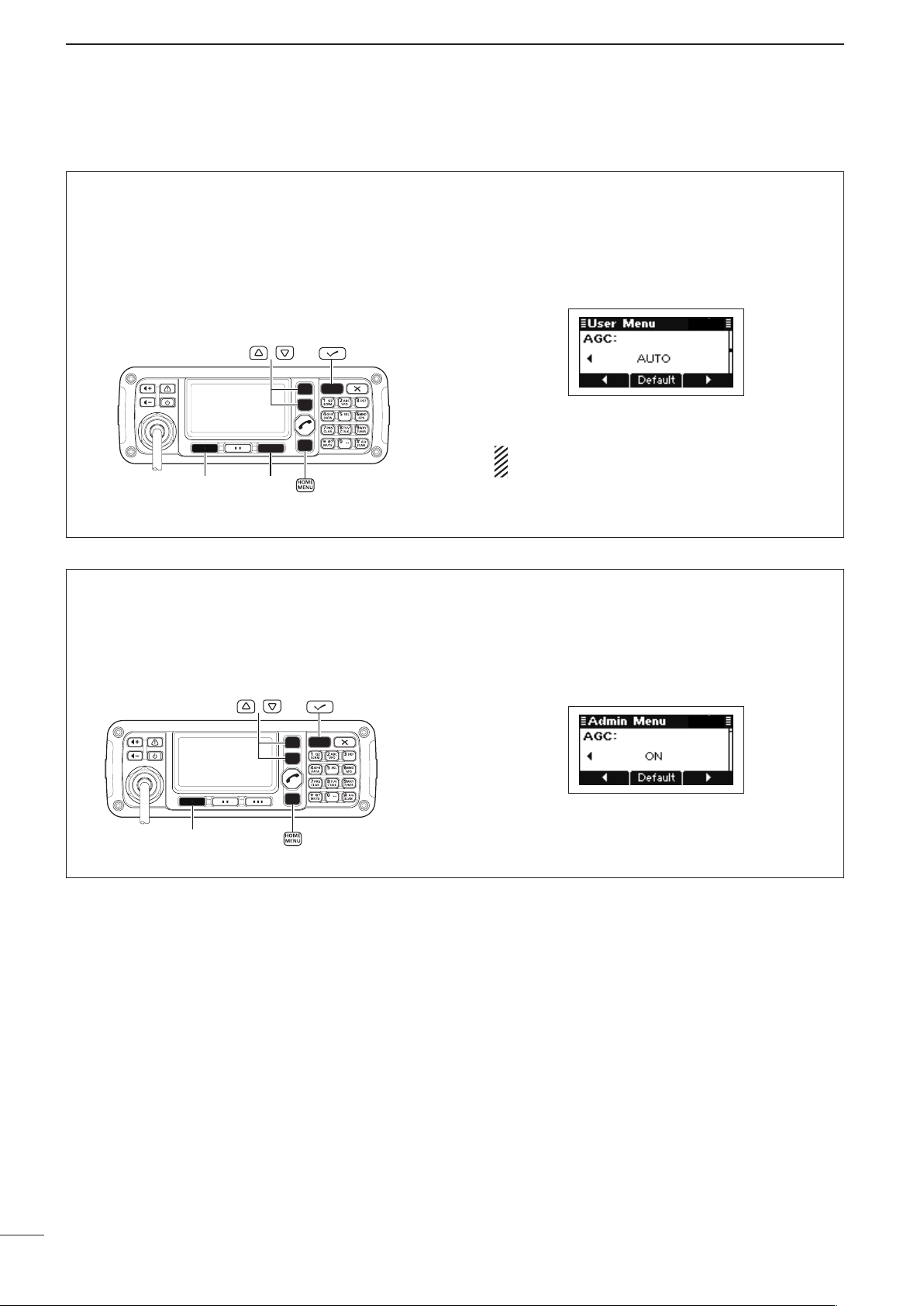
■ Functions for receive (Continued)
RECEIVE AND TRANSMIT
D AGC function
The AGC (automatic gain control) controls receiver
gain to produce a constant audio output level, even
when the received signal strength varies by fading,
and so on.
The transceiver has two AGC characteristics; AUTO
and time constants FAST and SLOW.
D AGC OFF function
When receiving weak signals with adjacent strong
signals or noise, the AGC function may reduce the
sensitivity. In this situation, the AGC function should
be turned OFF.
q Hold down [MENU](HOME) for 1 second to enter
the Menu screen.
w Push [r] or [s] to select the “User Menu,” and
then push [4].
e Push [r] or [s] to select “AGC.”
r Push [t](§) or [u](§§§) to select the desired AGC
time constant, FAST, SLOW or AUTO.
When AUTO is selected, the AGC time constant
varies, depending on the operating mode.
t Push [MENU](HOME) twice to return to the nor-
mal operating screen.
q Hold down [MENU](HOME) for 1 second to enter
the Menu screen.
w Push [r] or [s] to select the “Admin Menu,” and
then push [4].
e Push [r] or [s] to select “AGC.”
17
r Push [t](§) to turn OFF the AGC function.
t Push [MENU](HOME) twice to return to the nor-
mal operating screen.
 Loading...