

Page 1

ADVANCED MANUAL
INTRODUCTION
1 ADVANCED CONNECTIONS
2 ADVANCED OPERATIONS
3 ADVANCED SCOPE OPERATION
4 VOICE RECORDER FUNCTIONS
HF/50 MHz TRANSCEIVER
i7610
Instructions for advanced operations and additional
details are described in this manual.
See the Basic manual for the basic operations,
especially for new users.
5 VOICE TX MEMORY OPERATION
6
SD CARD/USB FLASH DRIVE (ADVANCED)
7 MEMORY OPERATION
8 SCANS
9 CLOCK AND TIMERS (ADVANCED)
10
ANTENNA TUNER OPERATION (ADVANCED)
11 OTHER FUNCTIONS
12 MAINTENANCE (ADVANCED)
13 UPDATING THE FIRMWARE
INDEX
Page 2

Table of contents
1. ADVANCED CONNECTIONS ............................... 1
137 kHz band operation ...................................... 1
Connecting the RC-28 ........................................ 2
Using the RC-28 ............................................... 2
FSK, AFSK, PSK connections ............................ 3
Connecting the AH-740 ....................................... 4
2. ADVANCED OPERATIONS .................................. 5
Band Edge Beep ................................................. 5
Entering Band Beep Edges .............................. 5
Adjusting the Drive Gain level ............................. 9
IP Plus function ................................................... 9
Tracking function .............................................. 10
VOX function ......................................................11
Adjusting the VOX function ..............................11
Turning ON the VOX function ..........................11
∂TX function ..................................................... 12
∂TX monitor function ...................................... 12
Operating CW (ADVANCED) ............................ 13
About the CW Reverse mode ......................... 13
Using the Memory Keyer function (KEYER) ... 13
Keyer memory edit menu (EDIT) ................... 14
Contest number menu (001 SET) ................... 15
Keyer set menu (CW-KEY SET) ..................... 16
Operating RTTY (FSK) ..................................... 17
Displaying the RTTY DECODE screen ........... 18
RTTY decoding ............................................... 18
Twin Peak Filter (TPF) .................................... 18
Transmitting an RTTY memory content .......... 19
Setting the RTTY Automatic TX/RX ................ 20
Editing an RTTY memory ................................ 21
Turning ON the RTTY log .............................. 22
Viewing the RTTY log contents ....................... 23
RTTY Decode Log set .................................... 23
Operating PSK .................................................. 25
Displaying the PSK DECODE screen 25
PSK decoding ................................................. 26
AFC/NET function ........................................... 26
Transmitting a PSK memory content 27
Setting the PSK Automatic TX/RX .................. 28
Editing a PSK memory .................................... 29
Turning ON the PSK log ................................ 30
Viewing the PSK log contents ......................... 31
PSK Decode Log set ...................................... 31
FM repeater operation ...................................... 33
Setting the repeater tone frequency 33
Checking the repeater input signal ................. 34
Tone squelch operation ..................................... 35
Data mode (AFSK) operation ........................... 36
Transverter operation ....................................... 36
Transverter setting example ........................... 36
About the 5 MHz frequency band operation ..... 37
3. ADVANCED SCOPE OPERATION ..................... 36
Spectrum Scope screen ................................... 36
Setting the Center mode span ........................ 36
Setting the Fixed mode range ......................... 36
Directly tuning to a signal ................................ 37
Dual Scope screen ......................................... 37
Sweep speed .................................................. 38
Adjusting the Reference level ......................... 38
SCOPE SET screen ......................................... 39
4. VOICE RECORDER FUNCTIONS ...................... 42
Recording a QSO audio .................................... 42
Using the [REC] key ....................................... 42
Using the [QUICK] key .................................... 42
Using the MENU screen ................................. 42
Playing back a QSO audio ................................ 43
Playing back a recorded audio on a PC ........... 44
Checking the folder information
and le information ......................................... 45
Deleting les ..................................................... 46
Deleting folders ................................................. 46
RECORDER SET screen ................................. 47
PLAYER SET screen ........................................ 48
INSTANT REPLAY SET screen ........................ 49
Instant Replay function ..................................... 49
Recording the Instant Replay ......................... 49
Playing back the Instant Replay ..................... 49
5. VOICE TX MEMORY OPERATION..................... 50
Recording a Voice TX memory ......................... 50
Recording ....................................................... 50
Playing back ................................................... 50
Entering a Voice TX memory name .................. 51
Transmitting a Voice memory content 52
Transmitting .................................................... 52
Repeatedly transmitting .................................. 53
Adjusting the output level ................................ 53
VOICE TX SET screen ..................................... 54
6. SD CARD/USB FLASH DRIVE (ADVANCED) ... 50
Saving the setting data onto
an SD card or USB ash drive .......................... 55
Loading the saved data les onto
an SD card or USB ash drive .......................... 56
Deleting a data le ............................................ 57
Displaying the SD card or USB ash drive
information ......................................................... 58
About the SD card and USB ash drive’s folders ...59
The SD card folder .......................................... 59
USB ash drive folder ..................................... 59
i
Page 3

Table of contents (Continued)
7. MEMORY OPERATION ...................................... 60
Memory channels ............................................. 60
Selecting a Memory channel ............................ 60
Entering memory channel contents .................. 61
Copying the Memory channel contents ............ 62
Copying to the VFO ........................................ 62
Copying to the other Memory channel 62
Entering a memory name ................................. 63
Clearing a memory channel .............................. 64
About the MEMORY screen ............................. 64
Memo Pad ........................................................ 65
Saving the displayed contents
into a Memo Pad ............................................ 65
Calling up the Memo Pads .............................. 65
8. SCANS ................................................................ 66
Scan types ........................................................ 66
Preparation ....................................................... 66
Squelch status ................................................ 66
SCAN screen .................................................... 67
SCAN SET screen ............................................ 67
Programmed scan ............................................ 68
Programmed scan operation .......................... 68
Memory scan .................................................... 69
Memory scan operation .................................. 69
Setting the Select Memory channels 69
Memory scan operation .................................. 70
∂F scan ............................................................ 71
∂F scan operation .......................................... 71
11. OTHER FUNCTIONS ......................................... 78
RF Direct Sampling System .............................. 78
About the RF/SQL Control ................................ 79
About “USB SEND/Keying” ............................... 80
Measuring SWR ................................................ 81
Selecting the Display Type ............................... 82
Selecting the Display Font ................................ 82
Displaying my call sign ..................................... 82
Screen Capture function ................................... 83
Setting the Screen Capture function 83
Capturing a screen ......................................... 83
Viewing a captured screen.............................. 83
REF adjustment ................................................ 84
12. MAINTENANCE ................................................ 85
Cleaning ............................................................ 85
Replacing fuse .................................................. 85
DC power cable fuses ..................................... 85
Circuitry fuse ................................................... 86
Touch screen calibration function ..................... 87
13. UPDATING THE FIRMWARE ........................... 88
General ............................................................. 88
About updating the rmware ........................... 88
Checking the rmware version ....................... 88
Preparation ..................................................... 89
Unzipping the rmware folder ......................... 89
Updating the rmware ....................................... 90
9. CLOCK AND TIMERS (ADVANCED) ................. 72
NTP function ..................................................... 72
Using the NTP Time Synchronize function ..... 72
Using the NTP function ................................... 72
Setting the Timers ............................................. 73
Setting the Sleep Timer .................................. 73
Setting the Daily Timer .................................... 74
Daily Timer setting items ................................. 75
10. ANTENNA TUNER OPERATION (ADVANCED) ....76
Using the [RX-I/O] in the Dualwatch operation ..........76
Selecting the antenna connector ...................... 77
Icom, Icom Inc. and the Icom logo are registered trademarks of Icom Incorporated (Japan) in Japan, the United States, the United Kingdom,
Germany, France, Spain, Russia, Australia, New Zealand and/or other countries.
Microsoft, Windows and Windows Vista are registered trademarks of Microsoft Corporation in the United States and/or other countries.
Adobe, Acrobat, and Reader are either registered trademarks or trademarks of Adobe Systems Incorporated in the United States and/or other
countries.
All other products or brands are registered trademarks or trademarks of their respective holders.
ii
Page 4
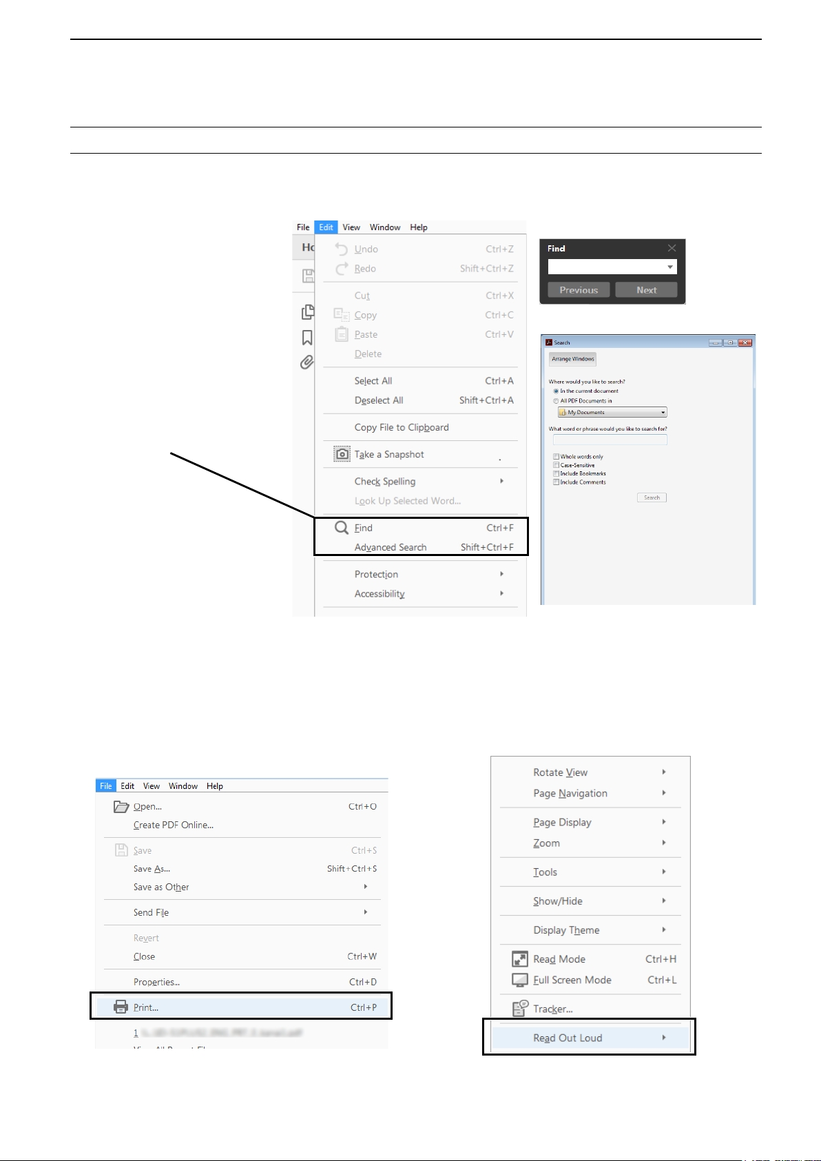
Functions and features of Adobe® Acrobat® Reader
The following functions and features can be used with Adobe® Acrobat® Reader®.
• Keyword search
Click “Find” (Ctrl+F)
or “Advanced Search”
(Shift+Ctrl+F) in the Edit menu to
open the search screen.
This is convenient when
searching for a particular word or
phrase in this manual.
* The menu screen may differ,
depending on the Adobe
Reader® version.
®
Acrobat
®
Click to open the nd or search
screen or advanced search screen.
• Find screen
• Advanced search screen
®
• Printing out the desired pages.
Click “Print” in File menu, and then select the paper
size and page numbers you want to print.
* The printing setup may differ, depending on the
printer. Refer to your printer’s instruction manual
for details.
* Select "A4" size to print out the page in the
equalized size.
• Read Out Loud feature.
The Read Out Loud feature reads aloud the text in
this Instruction Manual.
Refer to the Adobe
®
Acrobat® Reader® Help for the
details.
( This feature may not be usable, depending on your
PC environment including the operating system.)
* The screen may differ, depending on the Adobe® Acrobat
Reader® version.
iii
®
Page 5
1. ADVANCED CONNECTIONS
MENU
MENU
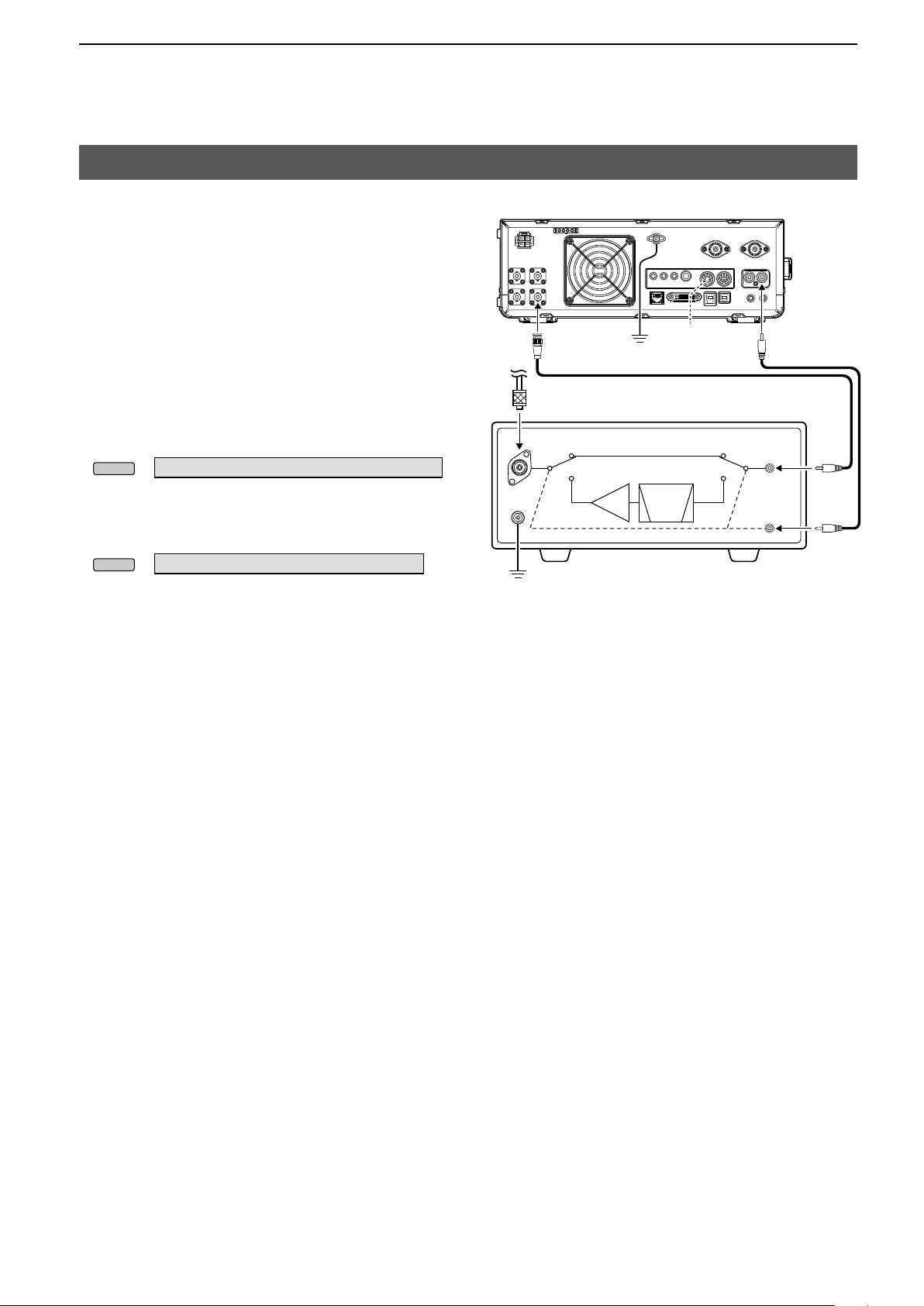
137 kHz band operation (European version only)
You can also operate between 135.7 kHz to 137.8
kHz in the CW mode.
The RF signal from [X-VERTER] is used for this
operation.
L The output of [X-VERTER] is –20 dBm so an up to
1 W linear amplier may be required.
LSee the connection illustration to the right.
[X-VERTER]
GND
★1
[SEND]
• Be sure to turn OFF the transceiver and the
amplier when connecting them.
• To enable the [X-VERTER] connector, set the
“Transverter Function” item to ON, or connect a DC
» SET > Function > Transverter Function
voltage to [ACC 2 (6: TRV)] (★1).
» SET > Function > Transverter Offset
• Set the offset frequency in the “Transverter Offset”
item to “0.000 MHz” to match the transceiver’s
operating frequency with the transmitting frequency.
• The antenna cannot be selected, and the internal
antenna tuner cannot be used while the Transverter
function is turned ON.
ANT
ANT
GND
Coaxial cable (50 Ω)
RX
TX TX
PA
BPF/
LPF
RX
Amplifier
[RF IN/
OUT]
[SEND]
1
Page 6
1. ADVANCED CONNECTIONS
MENU
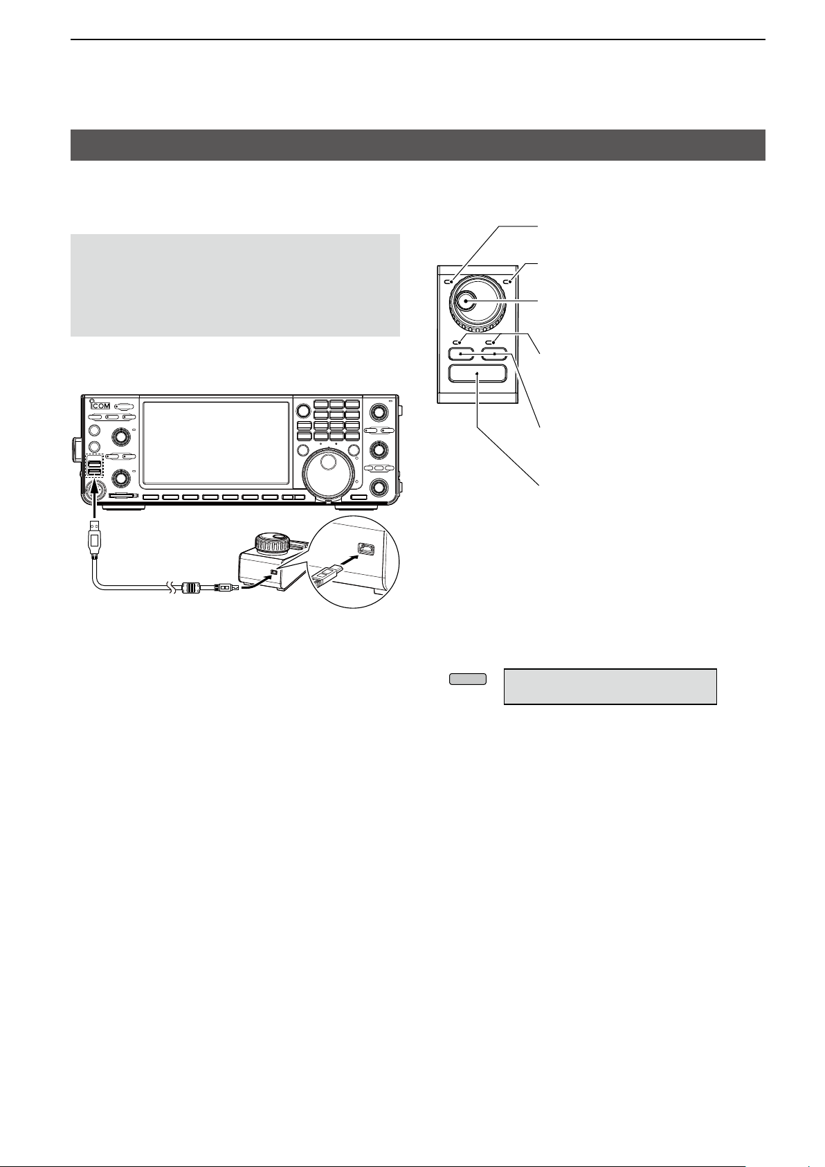
Connecting the RC-28
The optional RC-28 remote encoder can be used as
a sub dial.
NOTE:
• See the RC-28’s manual to use the RC-28 with the
RS-BA1 ip remote control software.
• Using the RC-28 with other than the USB cable
supplied with the RC-28, or connecting it through a
USB hub, is not guaranteed by Icom.
To a USB port
RC-28
D Using the RC-28
[TRANSMIT] LED
Lights while transmitting.
[LINK] LED
Lights while the RC-28 is connected to
the transceiver.
Main dial
Changes the Sub band’s operating
frequency (default).
[F-1]/[F-2] LEDs*
[F1] lights when operating the Main band,
and [F-2] lights when operating the Sub
band.
[F-1]/[F-2] buttons*
Selects the Main band or Sub band to
operate with the Main dial.
[TRANSMIT] button
Push to switch between transmit and
receive.
* The [F-1] and [F-2] buttons or keys are disabled
when “USB Dial Selectˮ is set to “SUB Only.ˮ
USB cable
(supplied with the RC-28)
L Setting the “USB Dial Select” to “MAIN/SUB”
enables you to operate both the Main band and the
Sub band, using the RC-28.
» SET > Connectors > USB DIAL >
USB DIAL SELECT
2
Page 7
1. ADVANCED CONNECTIONS
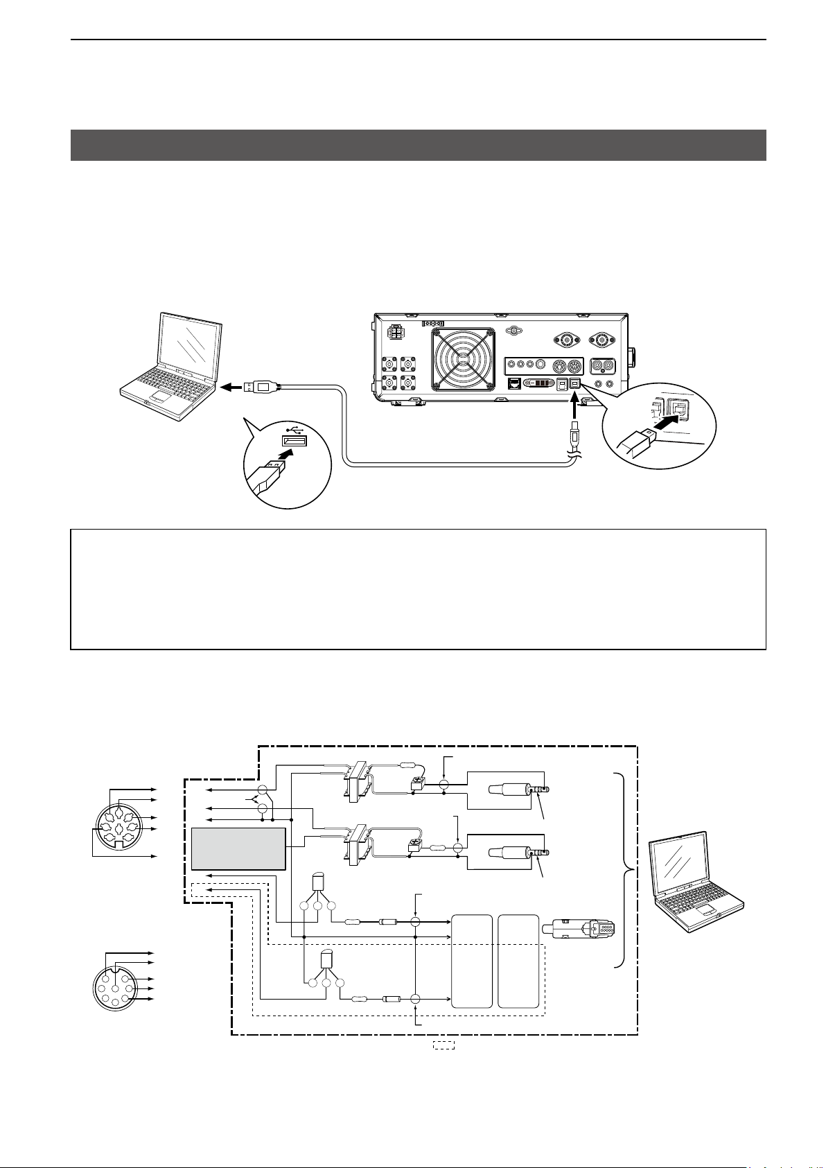
FSK, AFSK, PSK connections
The transceiver has a mode keys for RTTY and PSK. You can use a PC and an application software to operate
RTTY and PSK using a USB cable. However, if you want to operate AFSK or other digital modes, you can use
the ACC socket on the rear panel through an interface unit. See the interface circuit diagram below for details.
Refer to the software application’s instruction manual for setup details.
(Icom does not guarantee performance of the application software, PC, network device or network settings.)
When using the USB port
To a USB port
PC
To the USB port
Type B
Type A
A/B USB cable (user supplied)
TIP:
• If you set the “USB Serial Function” item to “RTTY Decode,” the decoded RTTY signals are output from the
USB port.
• Download the USB driver and the installation guide from the Icom website.
http://www.icom.co.jp/world/index.html
(Support > Firmware Updates/Software Downloads > Transceiver)
When using the ACC socket or the microphone connector
Interface circuit example for digital modes (User supplied)
• Connecting to [ACC 1]
D
2
4
1
8
6
C
5
E
3
B
7
A
(Rear panel)
• Connecting to [MIC]
D
E
1
7
2
8
3
4
F
6
C
5
B
E
Shield cable
D
C
ACC: Connect to [C]
MIC: Connect to [F]
B
A
2 kΩ: 2 kΩ 10 kΩ
2 kΩ: 2 kΩ
★1
CE B
4.7 kΩ
★1
CE B
4.7 kΩ
10 kΩ
(Trimpot)
10 kΩ
(Trimpot)
★2
★2
Shield cable
Shield cable
10 kΩ
Shield cable
D-Sub 25
RTS
GND
TXD
D-Sub 9
Pin 4
Pin 7
Pin 7
Pin 5
Pin 2 Pin 3
Connect to
LINE IN or
MIC IN
No connection
Connect to
SP OUT
No connection
Connect to
COM port
PC
(Front panel)
NOTE: You cannot
operate FSK RTTY when
you connect the circuit to
the microphone connector.
★1: NPN transistor
(2SC1815)
LSee pages 13-2 to 13-3 in the Basic Manual for details on the ACC 1 socket and MIC connectors.
★2: Switching diode
(1S1588)
Shield cable
The sections shown in short dashes are required only when
Baudot RTTY is used in the FSK (RTTY) mode.
(Not required for other digital modes such as SSTV or PSK)
3
Page 8
1. ADVANCED CONNECTIONS
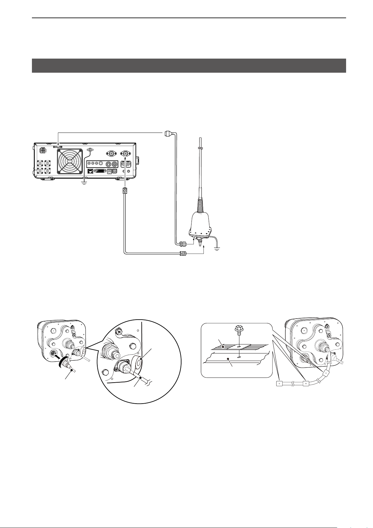
Connecting the AH-740
The optional AH-740 covers the 2.5 to 30 MHz range
with a supplied whip antenna. Or when using with the
optional NVIS kit, it covers the 2.2 to 30 MHz range.
L See the AH-740 instruction manual for installation
and connection details.
[TUNER]
The coaxial cable is supplied with the AH-740.
The OPC-2321 Control cable is an option.
GND
[ANT 1]
OPC-2321
Coaxial cable and control cable connections
Rubber
vulcanizing
tape, then
electrical
tape.
OPC-2321
Coaxial
cable
AH-740
GND
About the ground strap connection
Ground
strap
Vehicle chassis or body
4
Page 9
2. ADVANCED OPERATIONS
MENU
MENU
Band Edge Beep
You will hear a Band Edge Beep and
a border of short dashes) will be displayed when
you tune into or out of an amateur band’s frequency
range.
(“TX” with
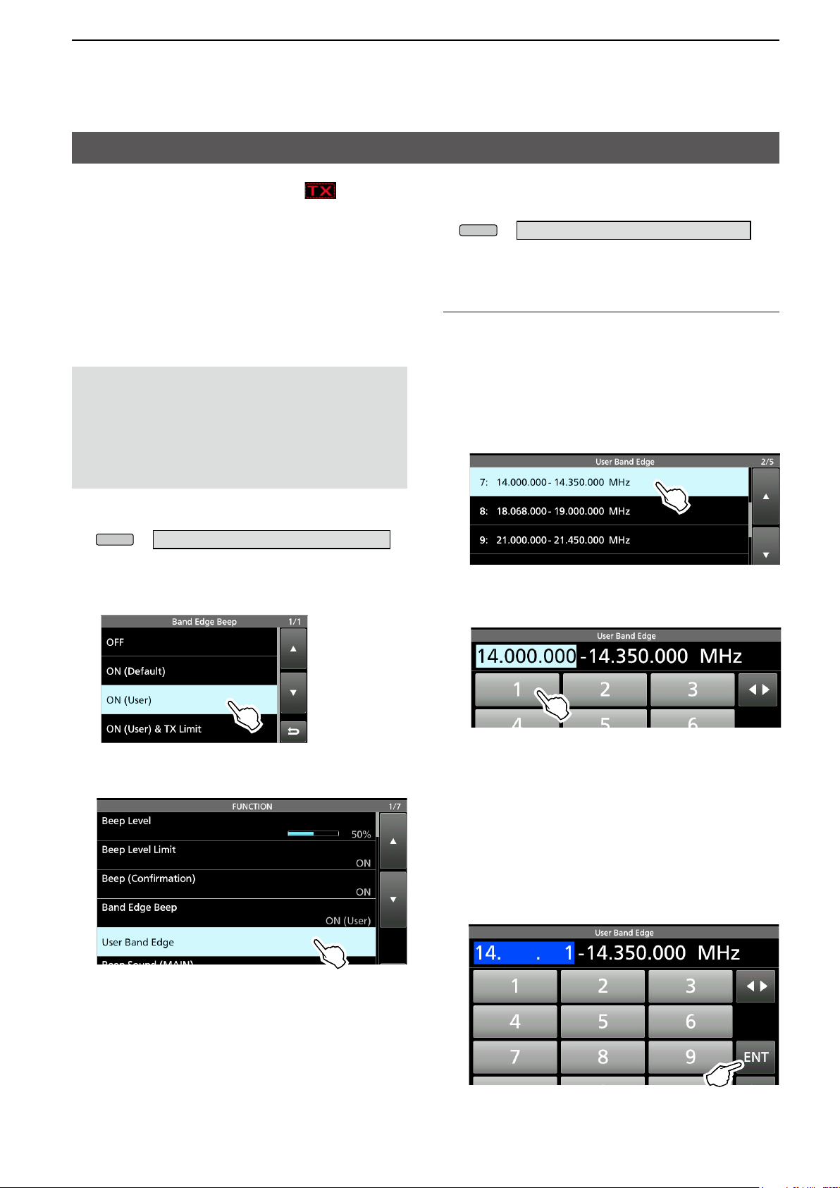
D Entering Band Beep Edges
When the “Band Edge Beep” item is set to “ON
(User)” or “ON (User) & TX Limit,” you can enter a
total of 30 band beep edge frequencies.
NOTE:
• Initially, all band edges are entered. Therefore, you
must rst edit or delete them to enter a new band
edge.
• You cannot enter an overlapped frequency or
a frequency that is out of the preset transmit
frequency band.
1. Open the “Band Edge Beep” screen.
» SET > Function > Band Edge Beep
2. Select “ON (User)” or “ON (User) & TX Limit.”
L If you select “ON (User) & TX Limit,” you can limit
transmission to within the entered frequency range.
L You can change the Band Edge Beep settings in
the following menu.
» SET > Function > Band Edge Beep
Editing a Band Edge
You can edit a band edge that is entered as a default,
or when entering a new band edge.
1. On the FUNCTION set screen, select “User Band
Edge.”
2. Touch the band edge you want to edit.
(Example: 7: 14.000.000 – 14.350.000 MHz)
3. Edit the lower band edge frequency.
(Example: 14.1)
3. Select “User Band Edge.”
• The “User Band Edge” screen is displayed.
Entry examples
• 14.025 MHz: [1], [4], [•], [0], [2], [5], [ENT]
• 18.0725 MHz: [1], [8], [•], [0], [7], [2], [5], [ENT]
• 730 kHz: [0], [•], [7], [3], [ENT]
• 5.100 MHz: [5], [•], [1], [ENT]
• 7.000 MHz: [7], [ENT]
• Changing from 21.280 MHz to 21.245 MHz:
[•], [2], [4], [5], [ENT]
4. Touch [ENT] to save the edited lower band edge
frequency.
(Continued on the next page)
5
Page 10
2. ADVANCED OPERATIONS
MAIN DIAL
MULTI
Band Edge Beep (continued)
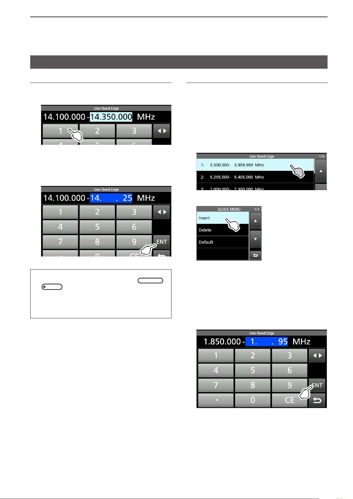
Editing a Band Edge (Continued)
5. Edit the upper band edge frequency.
(Example: 14.25)
6. Touch [ENT] to save the edited upper band edge
frequency.
L The edited band edge is saved and returns to the
previous screen.
Inserting a Band Edge
After you edit the preset band edges, follow the steps
below to insert a band edge.
1. Display the “User Band Edge” screen.
2. Touch the band edge you want to insert a new
band edge above for 1 second.
(Example: 1: 3.500.000–3.999.999 MHz)
L The new band edge will be inserted above the
selected band edge.
3. Touch “Insert.”
TIP:
• You can also edit the frequency by rotating
or
• Each band edge must be higher in frequency than the
ones above it. If you try to enter a lower frequency
than the edge above, the lower frequency edge will be
cleared when you push [ENT].
.
4. Enter the lower and upper band edge frequency.
(Example: 18.000.000 – 19.999.999 MHz)
L See Editing a Band Edge on the previous page for
details on entering the band edge frequencies.
5. Touch [ENT] to save the entered band edge
frequencies.
• The entered band edge is saved and returns to the
previous screen.
6
Page 11
2. ADVANCED OPERATIONS
Band Edge Beep (continued)
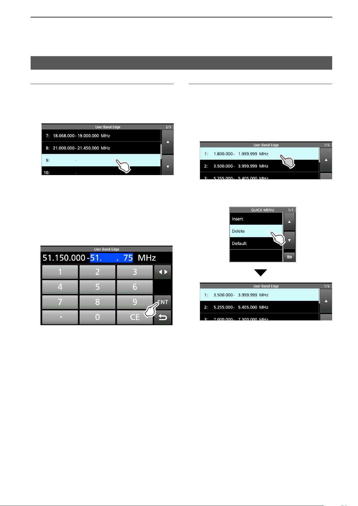
Entering a new Band Edge
After you edit (or delete) the preset band edges, you
can enter a new band edge.
1. Open the “User Band Edge” screen.
2. Select a blank band. (Example: 9)
3. Enter the lower and upper band edge frequency.
(Example: 51.150.000 – 51.750.000 MHz)
L See Editing a Band Edge on page 5 for details on
entering the band edge frequencies.
4. Touch [ENT] to save the entered band edge
frequencies.
• The entered band edge is saved and returns to the
previous screen.
Deleting a Band Edge
You can delete band edges doing the following steps.
1. On the FUNCTION set screen, select “User Band
Edge.”
2. Touch the band edge you want to delete for 1
second.
(Example: 1: 1.800.000 – 1.999.999 MHz)
3. Touch “ D e l e te.”
• The selected band edge is deleted and returns to the
previous screen.
1.800.000 – 1.999.999 MHz is deleted.
7
Page 12
2. ADVANCED OPERATIONS
Band Edge Beep (continued)
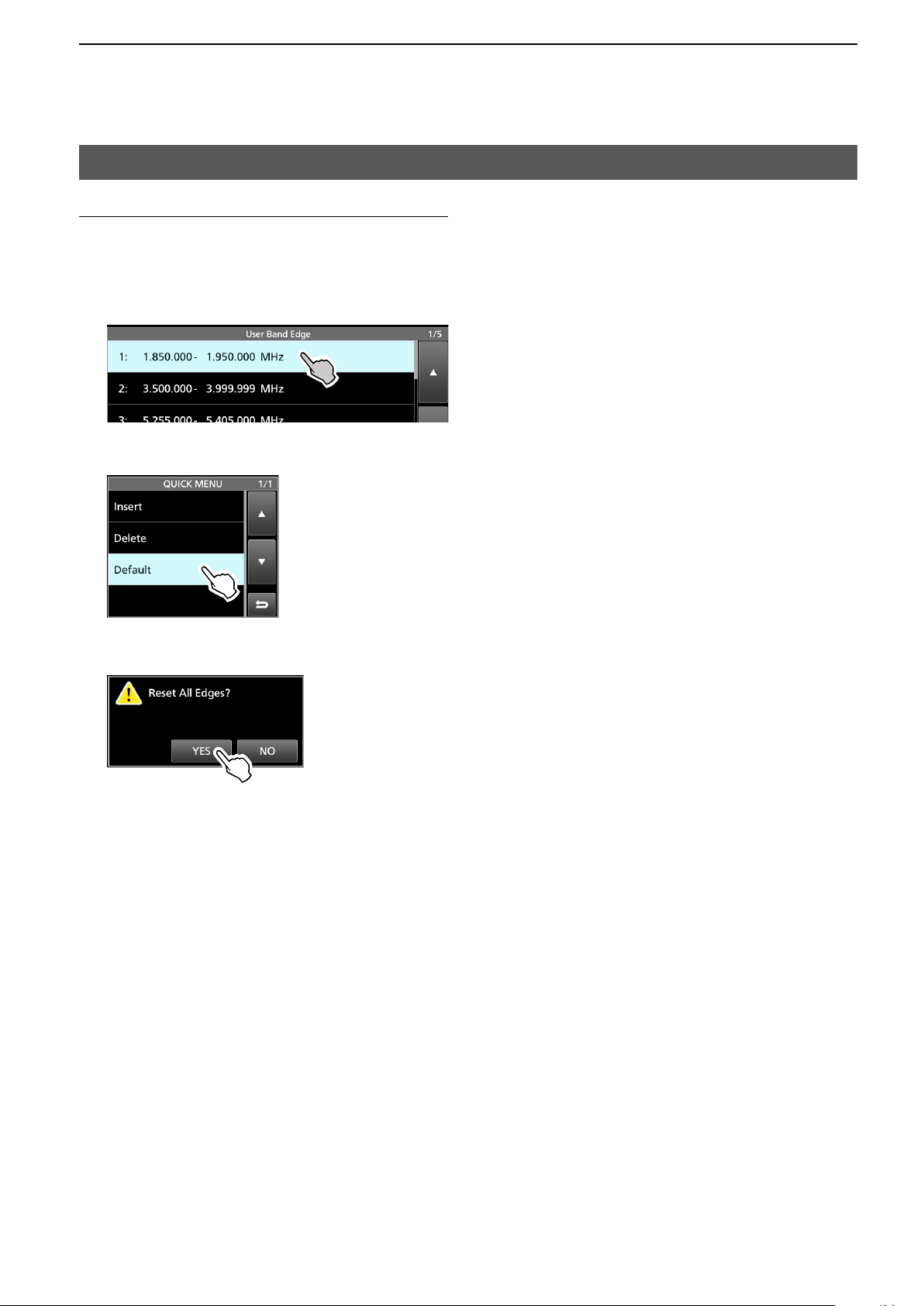
Resetting all band edges to presets
The steps below will reset all the band edges to their
initial settings. All entered settings will be deleted.
1. Display the “User Band Edge” screen.
2. Touch any band edge for 1 second.
3. Touch “Default.”
• Displays “Reset All Edges?”
4. Touch [YES].
• All the band edges will be reset to the initial settings.
8
Page 13
2. ADVANCED OPERATIONS
QUICK
TRANSMIT
MULTI
TRANSMIT
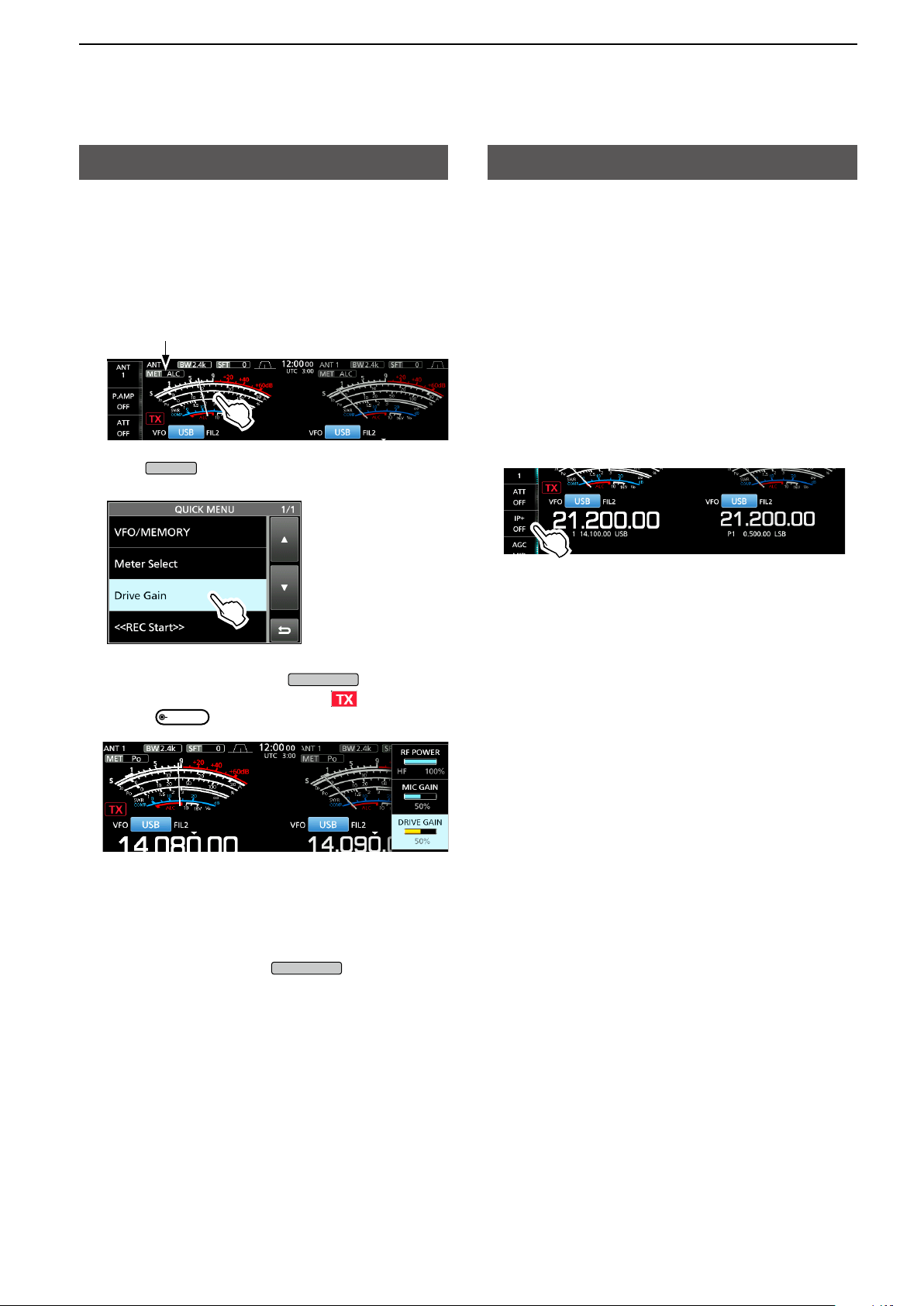
Adjusting the Drive Gain level
Adjust the transmitter level at the driver stage.
This reduces distortion in the transmitting signal.
L This function can be used in all modes, except in
the SSB with the Speech Compressor OFF.
1. Touch the meter to display the ALC meter.
ALC meter
2. Push
3. Touch “Drive Gain.”
.
IP Plus function
The IP Plus function improves the Intermodulation
Distortion (IMD) quality by optimizing the direct
sampling system performance.
This function optimizes the Analog/Digital Converter
(ADC) against distortion when you receive a strong
input signal. It also improves the Third-order Intercept
Point (IP3) while minimizing the reduction of the
receiver sensitivity.
Touch [IP+] on the side menu to turn the IP Plus
function ON or OFF.
ON: Prioritizes the IP quality.
OFF: Prioritizes the receive sensitivity.
4. Hold down [PTT] (or push
• The TX/RX indicator lights red and is displayed.
5. Rotate
L Adjust until the meter reading swings between 30
to 50% of the ALC scale, when speaking into the
microphone at your normal voice level or keying a
CW key.
to adjust the Drive Gain level.
6. Release [PTT] (or push
• Returns to receive.
).
).
9
Page 14
2. ADVANCED OPERATIONS
MENU
MAIN/SUB
MAIN DIAL
MAIN/SUB
MAIN/SUB
MENU
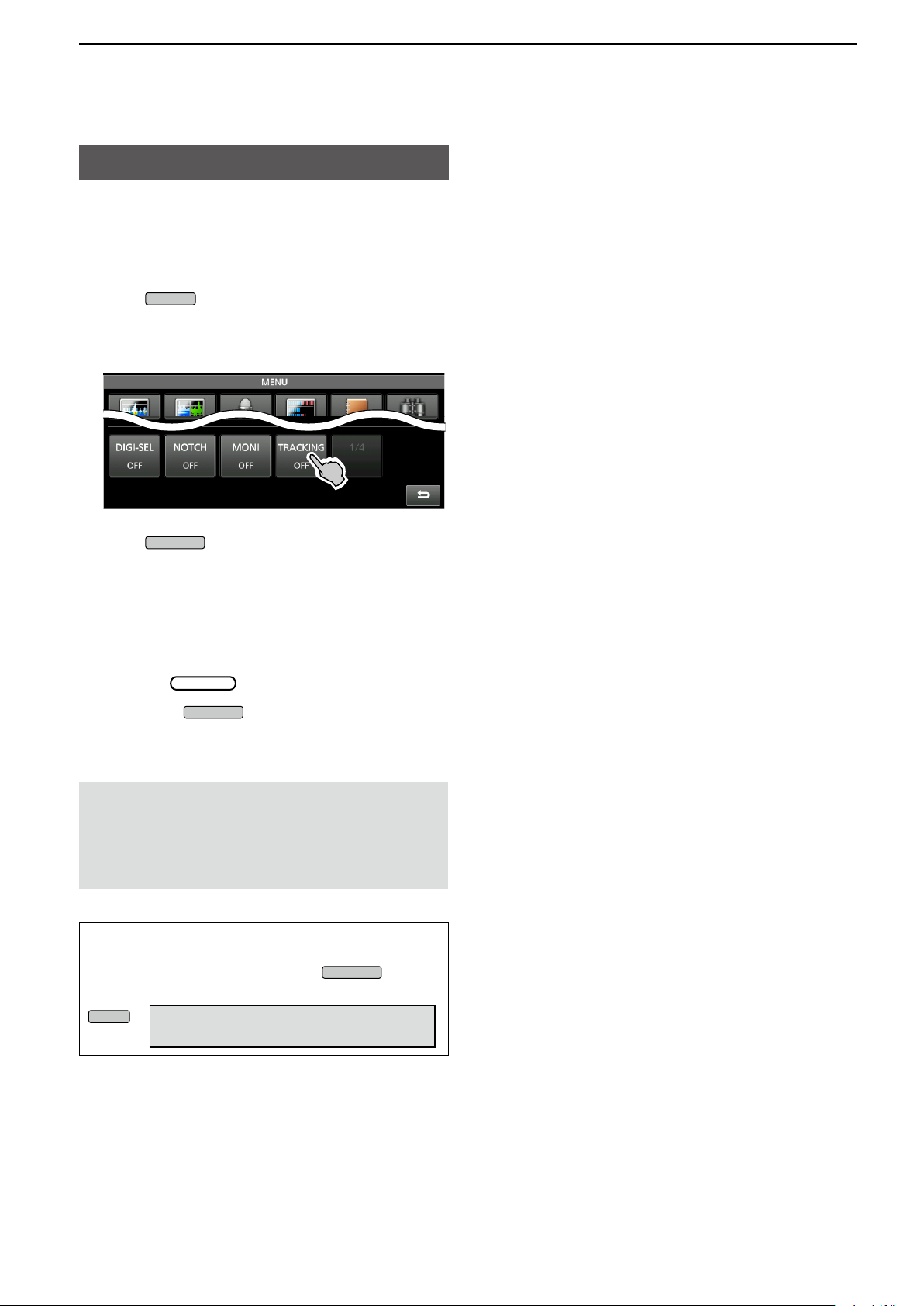
Tracking function
While in the Dualwatch operation, and when different
antennas are set to the Main and Sub bands, using
this function enables you to hear which antenna has
better reception.
1. Push
to display the MENU screen.
2. Touch [TRACKING] for 1 second to turn ON the
Tracking function.
• The MAIN/SUB indicator blinks in blue.
3. Push
to select the operating band
(Example: Main band).
• The MENU screen is closed.
L The Sub band’s operating frequency and mode are
synchronized with the Main band’s.
L When using the RC-28, if the offset frequency is
set between the Main band and the Sub band, the
frequency changes with the offset amount when
rotating
4. Hold down
.
for 1 second to turn OFF the
Tracking function.
The Tracking function will be canceled when:
• Starting a scan.
• Changing the operating band, or directly entering the
operating frequency on the Sub band.
• Changing from the Memory mode and the VFO mode,
vice versa, and so on.
TIP: Setting the “MAIN/SUB Tacking [MAIN/SUB]
Switch” item to ON enables you to turn ON the
Tracking function by holding down
for 1
second.
» SET > Function >
MAIN/SUB Tracking [MAIN/SUB] Switch
10
Page 15
2. ADVANCED OPERATIONS
MULTI
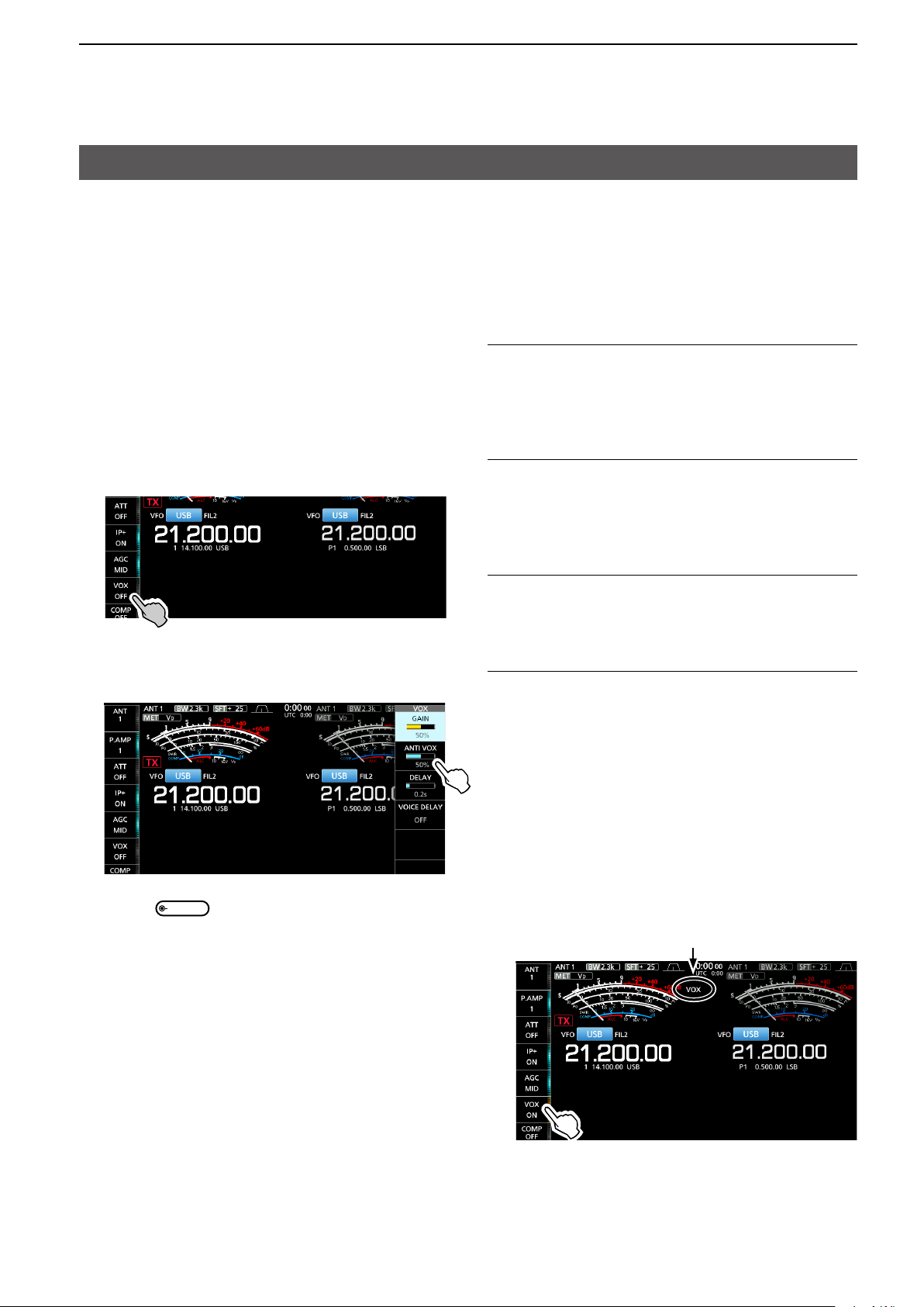
VOX function
Mode: SSB, AM and FM
The VOX (Voice-Operated Transmission) function
switches between transmit and receive with your
voice. This function enables hands-free operation.
D Adjusting the VOX function
Before using the VOX function, adjust the following
items.
• VOX GAIN
• ANTI VOX
• DELAY
• VOICE DELAY
1. Touch [VOX] for 1 second.
• Opens the VOX menu.
VOX GAIN (Default: 50%)
Adjust the transmit/receive switching threshold level
to between 0% and 100% for VOX operation. Higher
values make the VOX function more sensitive to your
voice.
ANTI VOX (Default: 50%)
Adjust the ANTI VOX level to between 0% and 100%
to prevent unwanted VOX activation from the speaker
or other sounds. Higher values make the VOX
function less sensitive.
2. Touch the adjusting item.
(Example: ANTI VOX)
3. Rotate
L Adjust to the point where the transceiver does not
switch to transmit due to the sound from the speaker
or other devices.
L Touching VOICE DELAY selects “SHORT,” “MID,”
“LONG” or “OFF.”
to adjust the selected item.
DELAY (Default: 0.2s)
Adjust the DELAY to between 0 and 2.0 seconds, for
a convenient interval for normal pauses in speech
before returning to receive.
VOICE DELAY (Default: OFF)
Set the VOICE DELAY to prevent picking up your
voice when switching to transmit.
Select “SHORT,” “MID,” “LONG” or OFF.
D Turning ON the VOX function
1. Set the operating mode to SSB, AM or FM.
2. Touch [VOX] to turn ON the VOX function.
• “VOX” is displayed while the VOX function is ON.
Displayed
L Touching [VOX] again turns OFF the VOX function.
11
Page 16
2. ADVANCED OPERATIONS
TX
TX
RIT/
TX
CLEAR
TX
TX
XFC
XFC
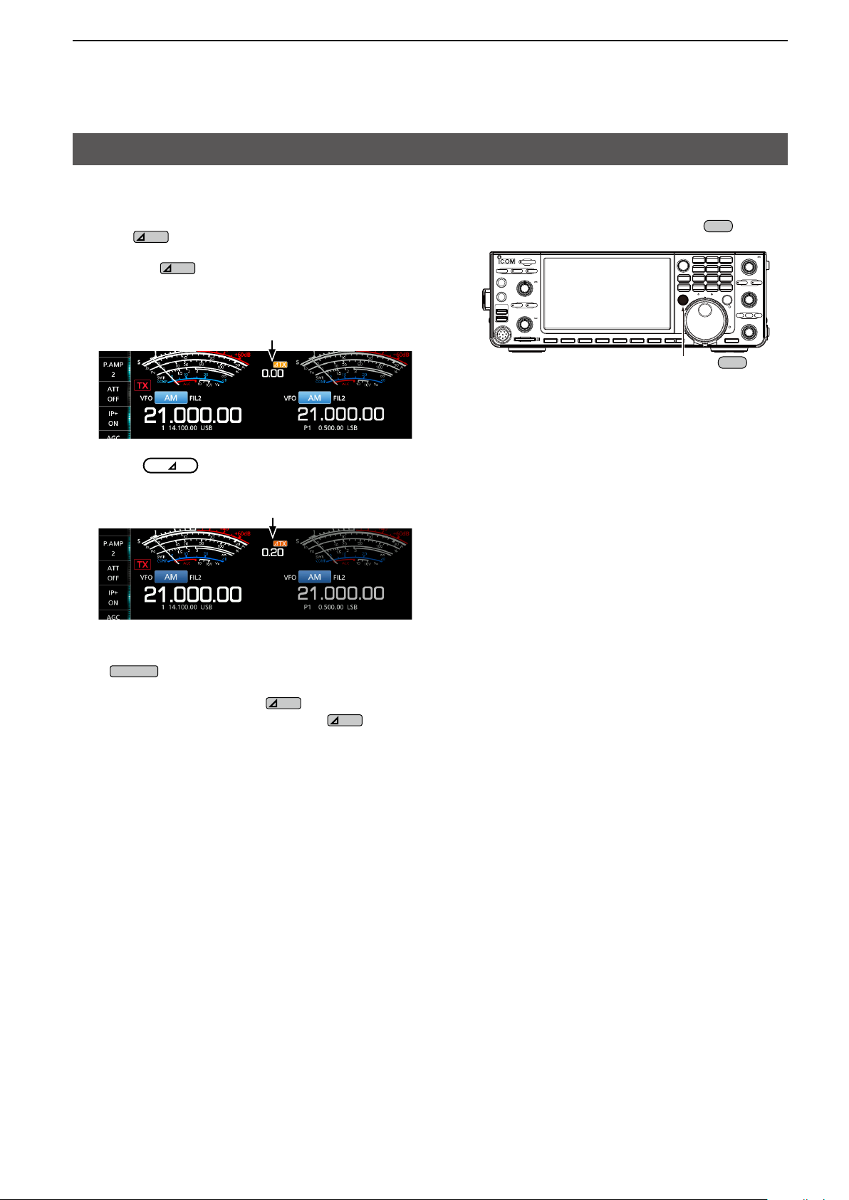
∂TX function
The ∂TX function shifts the transmit frequency up to
±9.99 kHz without shifting the receive frequency.
1. Push
• The ∂TX function turns ON.
LPushing
L While using the Fine Tuning function (See Basic
manual section 3), the ∂TX frequency is displayed in
4 digits, instead of 3.
2. Rotate
.
turns the ∂TX function ON or OFF.
∂TX frequency
to set the ∂TX frequency to
match the receiving station’s frequency.
Set the ∂TX frequency.
D ∂TX monitor function
When the ∂TX function is ON, you can directly monitor
the operating frequency by holding down
While holding down
L While monitoring, the TX/RX indicator lights green
and the Noise Reduction, Notch Filter and Twin PBT
settings are cleared.
.
.
L To reset the ∂TX frequency to “0.00,” hold down
for 1 second.
L You can add the frequency shift to the operating
frequency by holding down
for 1 second.
3. To turn OFF the ∂TX function, push
.
12
Page 17
2. ADVANCED OPERATIONS
MENU
MENU
TRANSMIT
Operating CW (ADVANCED)
D About the CW Reverse mode
The CW-R (CW Reverse) mode reverses the receive
Beat Frequency Oscillator (BFO) to receive CW
signals.
Use this when interfering signals are near the desired
signal and you want to use the CW-R to reduce
interference.
CW mode (LSB side) CW-R mode (USB side)
BFO BFO
Interference Desired
signal
TIP: Reversing the carrier point
The carrier point of the CW mode is LSB by default.
You can change it to USB on the FUNCTION screen.
» SET > Function > CW Normal Side
L When this setting is set to “USB,” the CW and CW-R
modes are reversed.
Interference Desired
signal
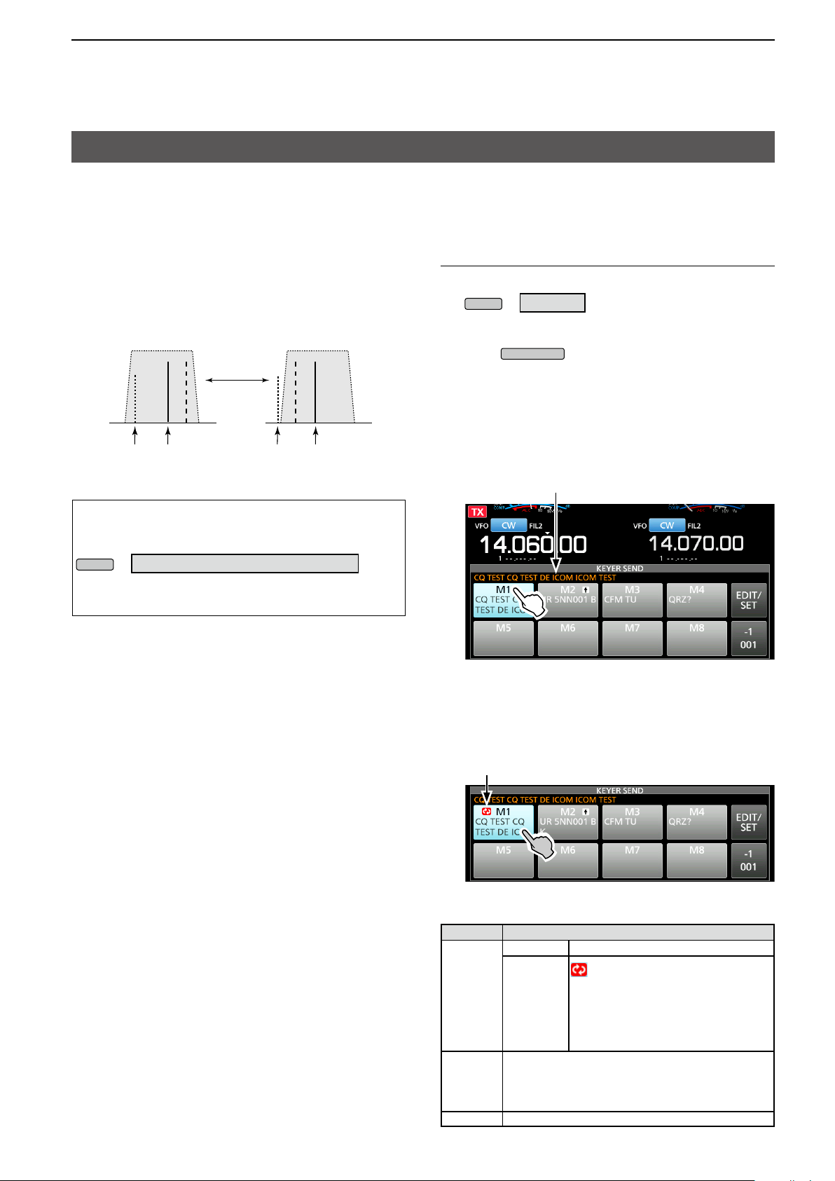
D Using the Memory Keyer function (KEYER)
You can send preset characters using the Memory
Keyer function.
Sending
1. Display the KEYER SEND screen.
» KEYER
L The [KEYER] key is displayed only in the CW mode.
2. Push
• The TX/RX indicator lights red.
L If you want to automatically switch between transmit
and receive, turn ON the Break-in function (See
Basic manual section 4).
3. Touch a Memory Keyer key between [M1] and [M8].
(Example: [M1])
• The touched Memory Keyer is sent.
Sending contents
.
The KEYER SEND screen while sending.
(Example: sending M1)
4. To stop sending, touch the Memory Keyer key again.
L The Memory contents will be repeatedly sent,
according to the setting in "Keyer Repeat Time."
Repeat icon
The KEYER SEND screen while repeatedly sending.
(Example: sending M1)
Key Action
Touch Sends the Memory keyer contents
is displayed and repeatedly
sends the Memory keyer contents.
L You can change the repeat interval
setting in “Keyer Repeat Time”
in the CW-KEY SET menu. (
Basic manual section 4
See Basic
)
13
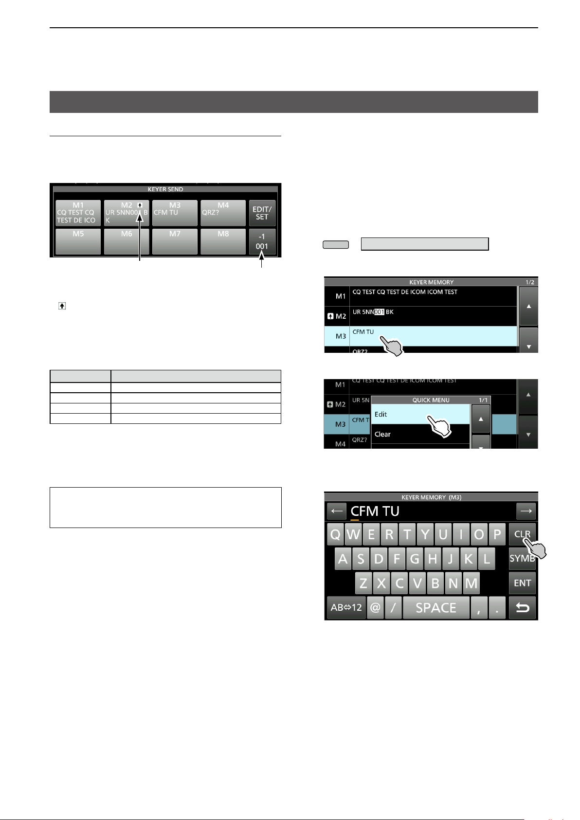
M1 ~ M8
–1
001
EDIT/SET
Touch for
1 second
Reduces the contest number counter by 1 (001).
L You can change or reset the number in “Present
Number” in the KEYER 001 menu. (
manual section 4
Touch to display the EDIT/SET screen.
See
)
Page 18
2. ADVANCED OPERATIONS
MENU
Operating CW (ADVANCED) (Continued)
Count up trigger
The count up trigger enables the serial number to be
automatically increased after each complete serial
number exchange is sent. (Default: M2)
Count up trigger icon
L is displayed on the Memory keyer set to the count up
trigger.
L You can change the count up trigger setting in the
KEYER 001 menu.
(See Basic manual section 4)
Present number counter
Preset Memory keyer contents
Memory keyer
M1 CQ TEST CQ TEST DE ICOM ICOM TEST
M2 UR 5NN 001 BK
M3 CFM TU
M4 QRZ?
L “001” is the CW contest number.
If you want to set the Count up trigger to different keyer,
select other keyer in “Keyer memory edit menu (EDIT)”
(See Basic manual section 4).
Using a USB keyboard or external keypad
You can send the preset contents without opening the
KEYER screen. See Basic manual section 13
Contents
).
D Keyer memory edit menu (EDIT)
Edit the Memory keyer contents in the EDIT menu.
L You can use up to a total of 8 Memory keyers (M1 to M8),
and you can enter up to 70 characters in each memory.
Editing
(Example: Entering “QSL TU DE JA3YUA TEST” to M3)
1. Display the KEYER MEMORY screen in the CW
mode.
» KEYER > EDIT/SET > EDIT
2. Touch “CFM TU” for 1 second.
3. Touch “Edit.”
4. Touch [CLR] on the Keyer Memory keyboard until
the preset contents are cleared.
(Continued on the next page)
14
Page 19
2. ADVANCED OPERATIONS
EXIT
MENU
EXIT
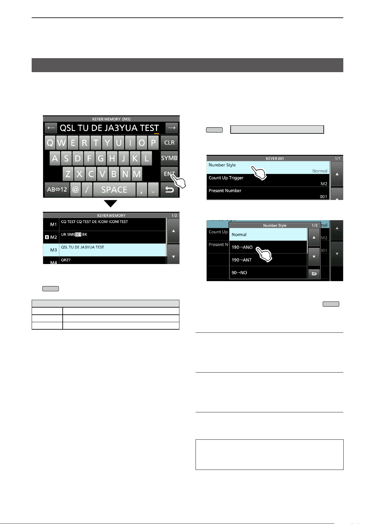
Operating CW (ADVANCED) (Continued)
D Keyer memory edit menu (EDIT) (Continued)
5. Enter “QSL TU DE JA3YUA TEST,” and then
touch [ENT] to save.
D Contest number menu (001 SET)
You can set the number style, count up trigger and
preset number.
Setting
1. Display the KEYER 001 menu in the CW mode.
» KEYER > EDIT/SET > 001 SET
2. Select the setting item.
(Example: Number Style)
3. Select the setting option.
6. To close the KEYER MEMORY screen, push
several times.
Selectable characters
Alphabets ABCDEFGHIJKLMNOPQRSTUVWXYZ
Symbols / ? ^ . , @ *
Numbers 1234567890
About the symbols
• Enter “^” to send a string of characters with no
intercharacter space. Put “^” before a text string such as
^AR, and the string “ar” is sent with no space.
• Enter “*” (asterisk) to insert the CW contest number. The
number automatically advances by 1. You can use this
for only 1 Memory keyer at a time. “*” is used in Memory
keyer M2 by default.
• Returns to the KEYER 001 menu.
4. To close the “Number Style” screen, push
several times.
Number Style (Default: Normal)
Set the numbering system used for contest (serial)
numbers— normal or short morse numbers.
• Select Normal, 190→ANO, 190→ANT, 90→NO or 90→NT.
Count Up Trigger (Default: M2)
Select which of the 8 memories will contain the
contest serial number exchange.
• Select between M1 ~ M8.
Present Number (Default: 001)
Set the current number for the Count Up Trigger.
• Set to between 001 ~ 9999.
TIP: How to reset to the default setting
Touching the item or its option for 1 second displays the
Quick menu, and then touch “Default” to reset to the
default setting.
15
Page 20
2. ADVANCED OPERATIONS
MENU
EXIT
AF RF/SQL
Operating CW (ADVANCED) (Continued)
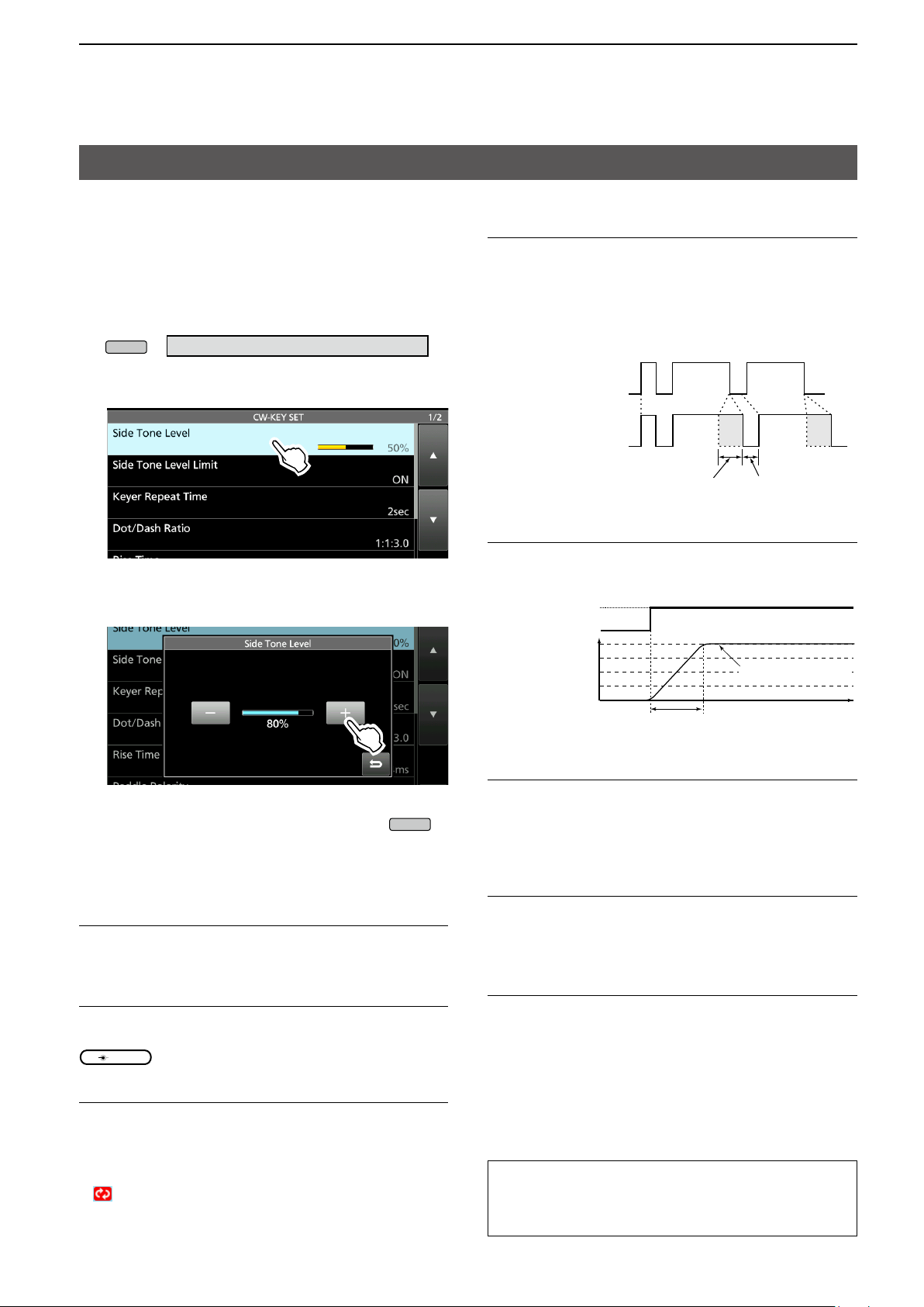
D Keyer set menu (CW-KEY SET)
In this menu, you can set the memory keyer repeat
time, dash weight, paddle specications, key type,
and so on.
Setting example
1. Display the CW-KEY SET menu in the CW mode.
» KEYER > EDIT/SET > CW-KEY SET
2. Select the setting item.
(Example: Side Tone Level)
Dot/Dash Ratio (Default: 1:1:3.0)
Set the dot/dash ratio.
• Set to between 1:1:2.8 ~ 1:1:4.5 in 0.1 steps.
Keying weight example: Morse code “K”
DashDashDot
11 3
Default: 1:1:3
112.8〜4.5
Setting range
1:1:2.8 to 1:1:4.5
3. Adjust the Side Tone Level.
(Example: 80%)
4. To close the CW-KEY SET screen, push
several times.
Side Tone Level (Default: 50%)
Adjust the CW side tone output level.
• Adjust to between 0 ~ 100%.
Side Tone Level Limit (Default: ON)
Turn the CW side tone level limit ON or OFF.
This disables the CW side tone when you rotate
(inner) above the side tone level.
Keyer Repeat time (Default: 2sec)
Set the time between Memory keyer transmissions.
• Set to between 1 ~ 60 seconds.
L After transmitting a Memory keyer, the transmission is
repeated after the set time period.
L
is displayed even between transmissions.
Setting range
Space
Rise Time (Default: 4ms)
Set the rise time of the transmitted CW envelope.
• Set to 2, 4, 6 or 8 milliseconds.
Key action
TX
RX
TX output
power
0
Rise time
Set TX output power
Time
Paddle Polarity (Default: Normal)
Set the paddle dot-dash polarity to Normal or
Reverse.
• Normal: Right = dash, Left = dot
• Reverse: Right = dot, Left = dash
Key Type (Default: ELEC-KEY)
Set the key type for the [KEY] connector on the front
panel.
• Set to Straight, Bug or Paddle.
MIC Up/Down Keyer (Default: OFF)
Set the microphone [UP]/[DN] keys to use as a CW
key.
• ON: Use the [UP]/[DN] keys as a CW key.
• OFF: Do not use the [UP]/[DN] keys as a CW key.
LThe [UP]/[DN] keys do not work as a “squeeze key.”
L When “ON” is selected, you cannot change the frequency
and the Memory channels using the [UP]/[DN] keys.
TIP: How to reset to the default setting
Touching the item or its option for 1 second displays the
Quick menu, and then touch “Default” to reset to the
default setting.
16
Page 21
2. ADVANCED OPERATIONS
HOLD
MAIN DIAL
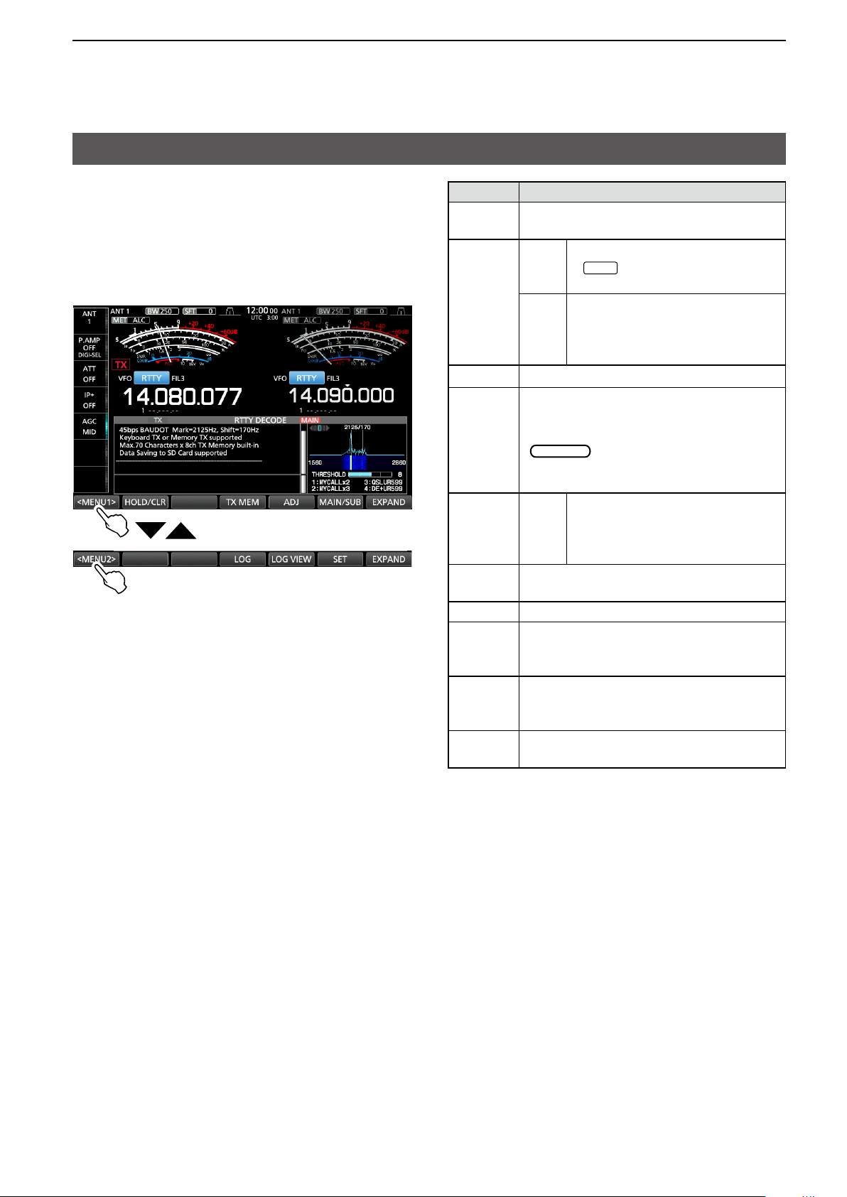
Operating RTTY (FSK)
The IC-7610 has a built-in RTTY decoder and
encoder. Using a USB keyboard and the contents
set in the RTTY TX memory, you can do basic RTTY
operations without using an external device or
software.
L If you are using PSK software, refer to the software manual.
RTTY DECODE screen <MENU1>
RTTY DECODE screen <MENU2>
Key Action
<MENU1>
<MENU2>
Selects the Function menus.
Turns the Hold function ON or OFF.
HOLD/
CLR
Touch
Touch
1 sec.
• “
” is displayed, and the
RTTY DECODE screen stops.
Clears the displayed characters.
• While the Hold function is ON,
this clears the characters and
cancels the Hold function.
TX MEM
Opens the RTTY MEMORY screen.
Opens the THRESHOLD screen.
You can adjust the threshold level.
ADJ
• Checking the RTTY DECODE, rotate
to adjust the threshold level to
where the characters are not displayed
by noise.
Resets the Threshold level to the
DEF
Touch
1 sec.
default.
L The [DEF] key is displayed
when after touching [ADJ].
MAIN/SUB
Changes between the Main or Sub band
RTTY DECODE screen.
EXPAND Selects the Expanded or Normal screen.
Displays the RTTY DECODE LOG screen.
LOG
• Starts/Stops logging, selects the le
type or the time stamp.
LOG
VIEW
SET
Displays the RTTY DECODE LOG VIEW
screen.
• You can check the saved RTTY log les.
Displays the RTTY DECODE SET
screen.
17
Page 22
2. ADVANCED OPERATIONS
APF/TPF
APF/TPF
APF/TPF
MAIN DIAL
BFOBFO
MENU
MENU
MENU
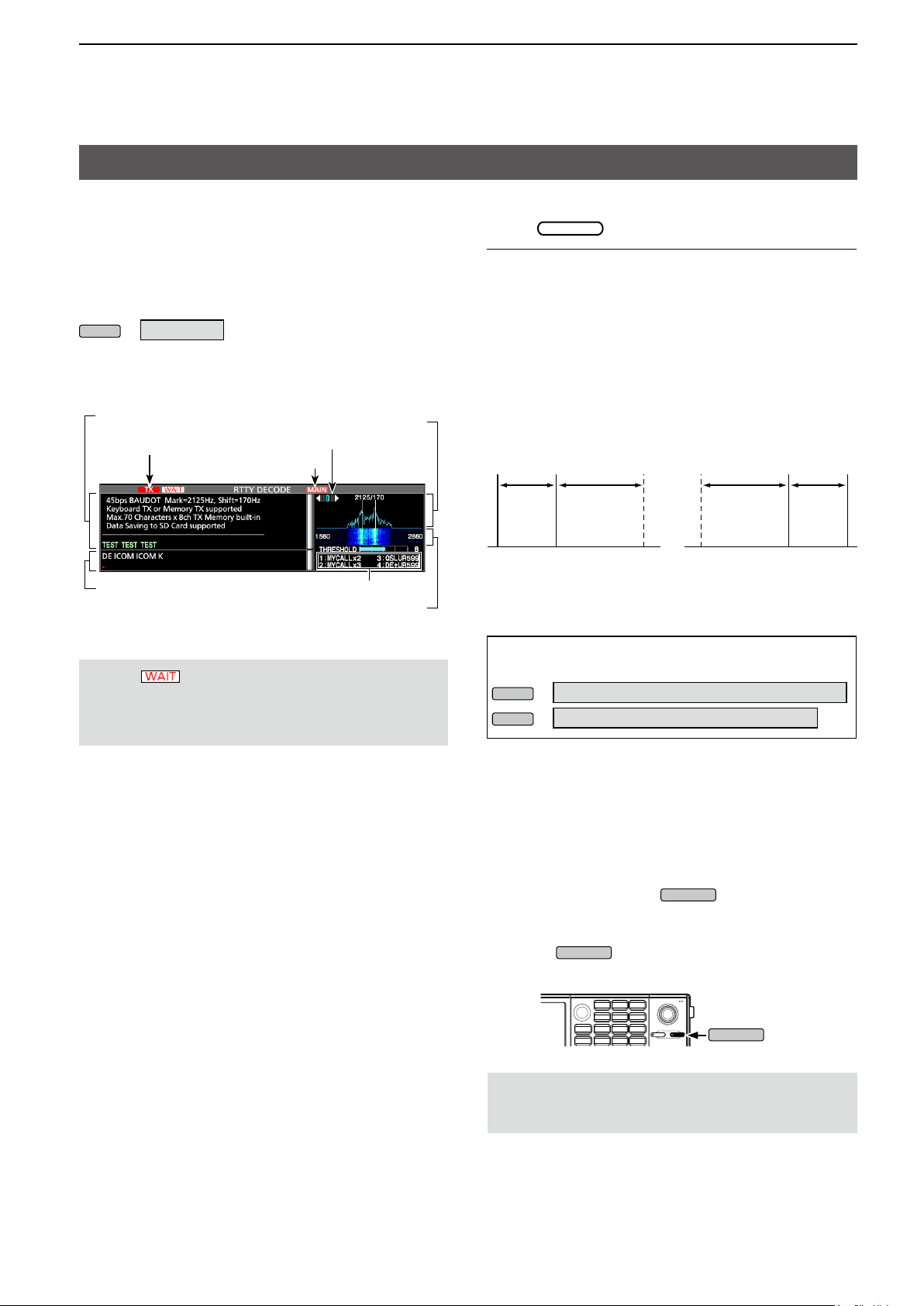
Operating RTTY (FSK) (Continued)
D Displaying the RTTY DECODE screen
With the built-in demodulator and decoder, received
RTTY signals are displayed on the RTTY DECODE
screen.
L The decode screen for the PSK mode differs
slightly from that of the RTTY mode.
» DECODE
RTTY DECODE screen
Decoded characters
Transmitting
Transmitting contents
(Example: RT1)
Selected band (MAIN)
RTTY memory title
NOTE: “ ” appears next to the transmitting
status indicator on the RTTY DECODE screen while
buffering. If this appears, stop typing for a while and
try transmitting again.
FFT scope
Tuning indicator
Waterfall display
D RTTY decoding
Rotate
InformationL
• Aim for a symmetrical wave form, and be sure the peak
points align with the mark (2125 Hz) and shift (170 Hz)
frequency lines in the FFT scope.
• Tune to where both “◄” and “►” are displayed in the
tuning indicator.
• The S-meter displays the received signal strength,
when a signal is received.
• If you are receiving an RTTY signal but cannot decode
correctly, try in the RTTY-R (reverse) mode.
RTTY mode Normal RTTY-R mode
170 Hz 2125 Hz 170 Hz2125 Hz
Space
Mark
( Displayed
frequency)
TIP: If you cannot receive, change the settings for
“RTTY Mark Frequency” and “RTTY Shift Width.”
»
SET > Function > RTTY Mark Frequency
» SET > Function > RTTY Shift Width
to tune a signal.
Space
( Displayed
frequency)
Mark
D Twin Peak Filter (TPF)
The Twin Peak Filter (TPF) changes the audio
frequency response by boosting the mark and space
frequencies for better reception of RTTY signals, or
for decoding the AF output signal on a PC.
In the RTTY mode, push
• The TPF function is turned ON, and the indicator on the
key lights.
L Pushing
or OFF.
turns the Twin Peak Filter function ON
NOTE: When you are using the Twin Peak Filter, the
received audio output may increase. This is not a
malfunction.
.
18
Page 23
2. ADVANCED OPERATIONS
MENU
EXIT
MENU
Operating RTTY (FSK) (Continued)
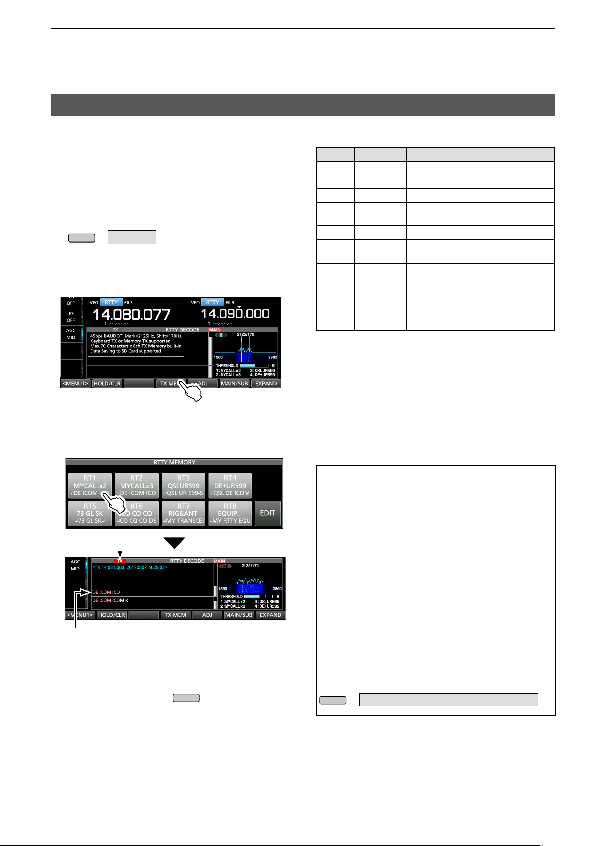
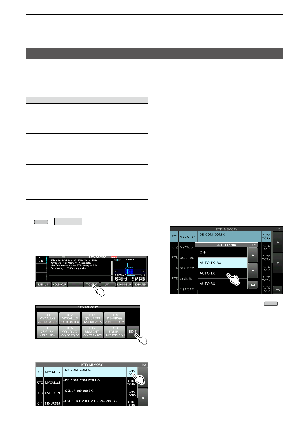
D Transmitting an RTTY memory content
You can transmit the preset characters on the RTTY
MEMORY screen.
L You can edit the characters by touching [EDIT] on the
RTTY MEMORY screen.
1. Display the RTTY DECODE screen in the RTTY
mode.
» DECODE
L The PSK mode screen differs slightly from the
RTTY mode.
2. Touch [TX MEM].
Memory
RT1 MYCALLx2
RT2 MYCALLx3
RT3 QSLUR599
RT4 DE+UR599
RT5 73 GL SK
RT6 CQ CQ CQ
RT7 RIG&ANT
RT8 EQUIP.
Title Preset characters by default
↵ DE ICOM ICOM K ↵
↵ DE ICOM ICOM ICOM K ↵
↵ QSL UR 599–599 BK ↵
↵ QSL DE ICOM ICOM UR 599-
599 BK ↵
↵ 73 GL SK ↵
↵ CQ CQ CQ DE ICOM ICOM
ICOM K ↵
↵ MY TRANSCEIVER IS IC
& ANTENNA IS A 3–ELEMENT
TRIBAND YAGI. ↵
↵ MY RTTY EQUIPMENT
IS INTERNAL FSK UNIT &
DEMODULATOR OF THE IC-7610. ↵
-
7610
3. Touch an RTTY memory between [RT1] and
[RT8] to transmit.
(Example: RT1)
Lights red
Transmitting contents are displayed.
• The TX status indicator lights red and the Po meter
swings.
L To cancel the transmission and to return to the RTTY
DECODE screen, push
LAfter transmitting, automatically returns to receive.
.
When a keyboard is connected:
• You can transmit the preset contents in the RTTY
memory (RT1 ~ RT8) by pushing [F1] ~ [F8] on the
USB keyboard.
After transmitting the contents, you can directly
enter an RTTY message on the keyboard, and
then push [F12] to transmit.
To return to receive, push [F12] again.
• If the Auto TX/RX function is set to “OFF” or
“AUTO RX” (p. 20), you can display the preset
contents on the RTTY DECODE screen, and then
transmit it by pushing [F12] on the keyboard.
• You can transmit the preset contents in the RTTY
memory (RT1 ~ RT8) from an external device by
setting the “External Keypad,” and then connecting
an external keypad to [MIC] or [EXT KEYPAD] on
the IC-7610.
» SET > Connectors > External Keypad
19
Page 24
2. ADVANCED OPERATIONS
MENU
EXIT
Operating RTTY (FSK) (Continued)
D Setting the RTTY Automatic TX/RX
You can set to automatically transmit the RTTY
memory contents, or to automatically return to receive
after transmitting each memory (RT1 ~ RT8).
Selection
OFF
AUTO TX/RX
AUTO TX
AUTO RX
The selected memory contents are
displayed on the RTTY DECODE screen.
Push [F12] on the keyboard to transmit
the selected memory, and push [F12]
again to return to receive.
Automatically transmits the selected
memory and returns to receive.
Automatically transmits the selected
memory, and then returns to receive by
pushing [F12] on the keyboard.
The selected memory contents are
displayed on the RTTY DECODE screen.
Push [F12] on the keyboard to transmit
the selected memory, and then it
automatically returns to receive after
transmission.
Action
1. Display the RTTY DECODE screen.
» DECODE
L The PSK mode screen slightly differs from the
RTTY mode.
5. Touch to select an option.
(Example: AUTO TX)
2. Touch [TX MEM].
3. Touch [EDIT ] .
4. Touch the setting memory’s option.
(Example: RT1’s AUTO TX/RX)
6. To exit the RTTY DECODE screen, push
several times.
20
Page 25
2. ADVANCED OPERATIONS
QUICK
EXIT
MENU
Operating RTTY (FSK) (Continued)
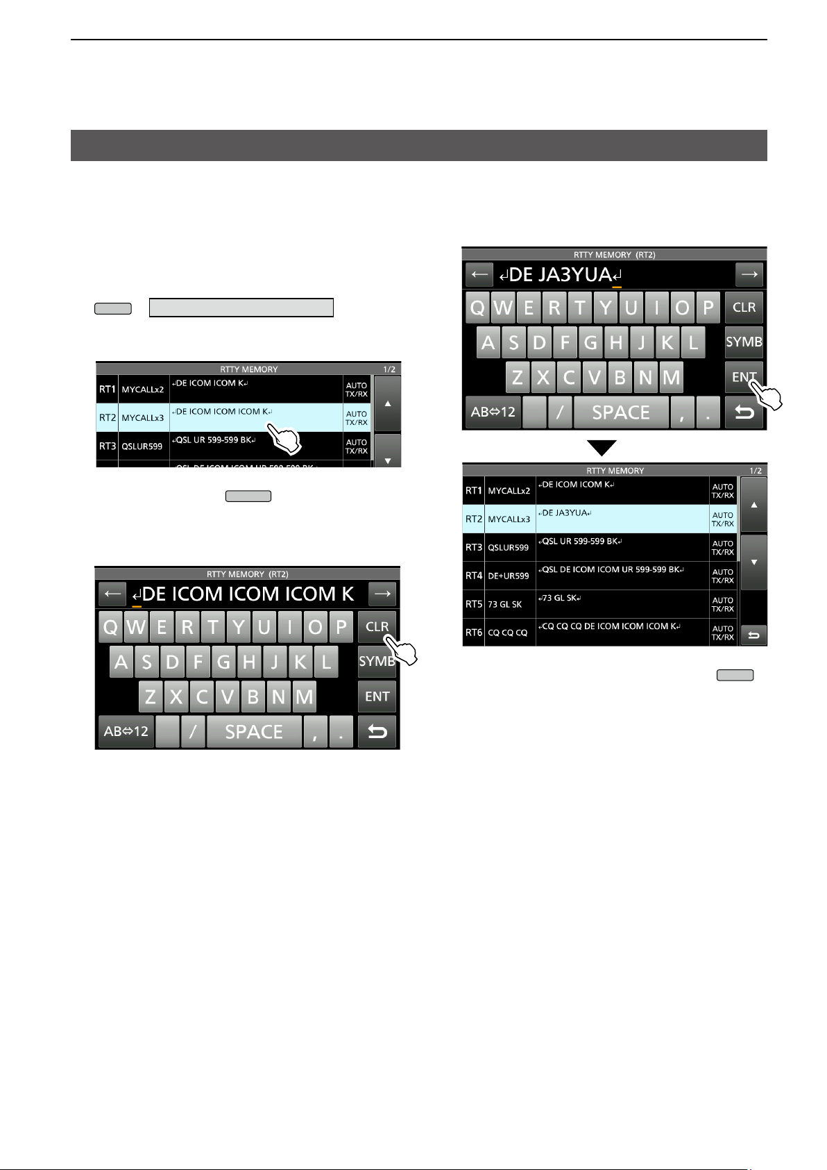
D Editing an RTTY memory
You can edit the characters in the RTTY memories.
You can save and transmit 8 RTTY memories for
often-used RTTY messages.
Each RTTY memory can contain up to 70 characters.
1. Display the RTTY MEMORY editing screen.
» DECODE > TX MEM > EDIT
2. Touch the memory to edit the content.
(Example: RT2)
4. Enter the new characters, and then touch [ENT]
to save.
L You can also push
, and then touch
“Edit Memory Content.”
3. To clear a character, touch [←] or [→] to move the
cursor, then touch [CLR].
5. To exit the RTTY DECODE screen, push
several times.
21
Page 26
2. ADVANCED OPERATIONS
MENU
EXIT
Operating RTTY (FSK) (Continued)
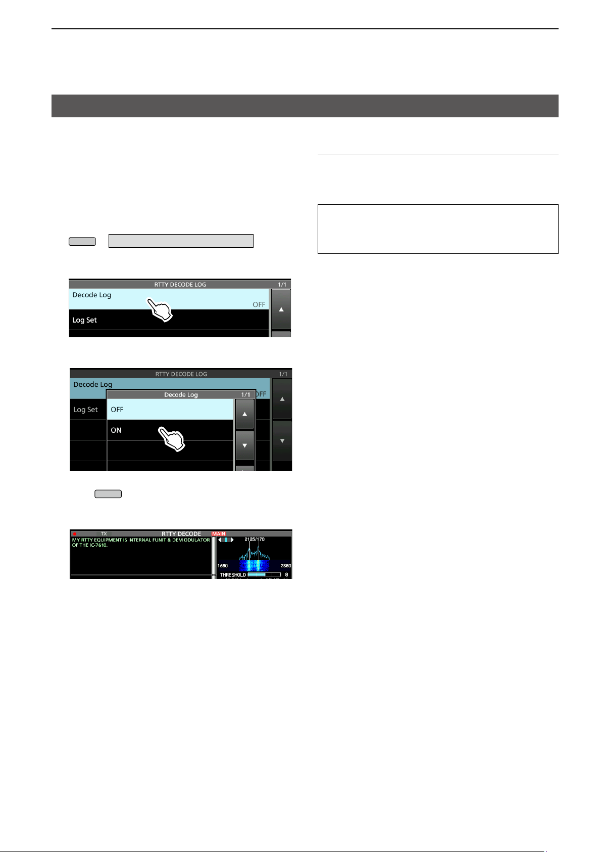
D Turning ON the RTTY log
Turn ON the RTTY log to save your TX and RX RTTY
operating record onto an SD card.
L You can select the data format type in the “Log Set”
item on the RTTY DECODE LOG screen.
LThe log is saved even while “HOLD” is ON.
1. Display the RTTY DECODE LOG screen.
» DECODE > <MENU1> > LOG
2. Touch “Decode Log.”
Log Set > File Type (Default: Text)
Set the le type to save a log onto an SD card to
“Text” or “HTML.”
L You cannot change the le type while logging.
TIP: How to reset to the default setting
Touching the item or its option for 1 second displays the
Quick menu, and then touch “Default” to reset to the
default setting.
3. Select “ON.”
4. Push
• “●” is displayed on the RTTY DECODE screen while
the RTTY log is ON.
.
5. To turn OFF the RTTY log, select “OFF” in step 3.
22
Page 27
2. ADVANCED OPERATIONS
MENU
EXIT
MENU
EXIT
Operating RTTY (FSK) (Continued)
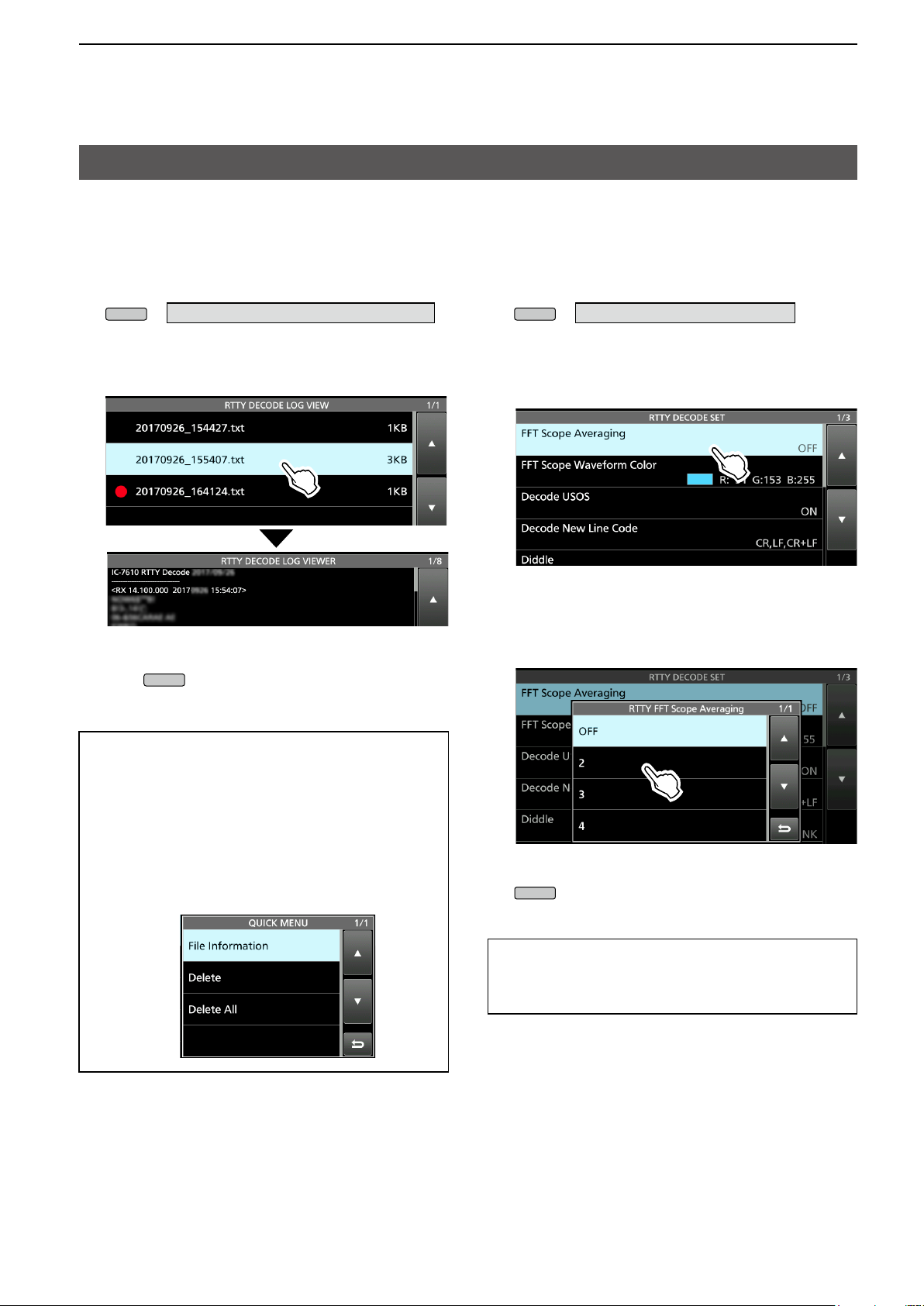
D Viewing the RTTY log contents
You can view the saved RTTY log contents.
1. Insert the SD card that the RTTY log is saved.
2. Display the RTTY DECODE LOG VIEW screen.
» DECODE > <MENU1> > LOG VIEW
3. Touch the log file to view.
L The le with “●” is logging. You cannot view this log’s
contents.
4. To exit the RTTY DECODE LOG VIEW screen,
push
several times.
D RTTY Decode Log set
This mode is for the log le type, time stamp setting,
and other RTTY settings.
1. Display the RTTY DECODE SET screen.
» DECODE > <MENU1> > SET
2. Select an item to set.
(Example: FFT Scope Averaging)
3. Select a setting option.
(Example: 2)
L See the next page for details on the setting
items and their options.
Checking the le information and deleting a le
1. Touch the log file that you want to view or delete
for 1 second.
2. Select an item from “File Information,” “Delete”
and “Delete All.”
• File Information: Displays the le name, size and
logged date.
• Delete: Deletes the selected log le.
• Delete All: Deletes all log les.
4. To exit the RTTY DECODE SET screen, push
several times.
TIP: How to reset to the default setting
Touching the item or its option for 1 second displays the
Quick menu, and then touch “Default” to reset to the
default setting.
23
Page 28

2. ADVANCED OPERATIONS
MULTI
MULTI
Operating RTTY (FSK) (Continued)
D RTTY Decode log set (Continued)
FFT Scope Averaging (Default: OFF)
Set the FFT scope waveform averaging function to
between 2 and 4, or to OFF.
L Use the default or a smaller FFT scope waveform
number for tuning.
FFT Scope Waveform Color
(Default: R: 51, G: 153, B: 255)
Set the color of the FFT scope waveform.
L Touch and select the R (Red), G (Green) or B (Blue)
scale, and then rotate
between 0 and 255.
LThe color is displayed in the box above the RGB scale.
to adjust the ratio to
Decode USOS (Default: ON)
Turn the letter code decoding capability ON or OFF
after receiving a “space.”
LUSOS stands for UnShift On Space function.
• ON: Decodes as a letter code.
• OFF: Decodes as a character code.
Decode New Line Code (Default: CR, LF, CR+LF)
Select the internal RTTY decoder new line code.
L CR stands for Carriage Return, and LF stands for Line
Feed.
• CR,LF,CR+LF: Makes a new line with any codes.
• CR+LF: Makes a new line with only CR+LF code.
Diddle (Default: BLANK)
Select the diddle status code.
While transmitting in the RTTY mode, the selected
code is transmitted when there is no code to transmit.
• OFF: Turns OFF the Diddle function.
• BLANK: Transmits blank codes.
• LTRS: Transmits letter codes.
Time Stamp (Default: ON)
Select whether or not display the time stamp (date,
transmission time and reception time) on the RTTY
DECODE screen and add it in the log.
• OFF: Does not display or add the time stamp.
• ON: Displays and adds the time stamp in the log.
Time Stamp (Time) (Default: Local)
Select whether or not to display the log on the RTTY
DECODE screen and to save it, with the local time or
with the UTC time when “Time Stamp” is ON.
• Local: Displays and saves in the local time.
• UTC: Displays and saves in the UTC.
Time Stamp (Frequency) (Default: ON)
Select whether or not to display the frequency
information on the RTTY DECODE screen and to
save it as a log when “Time Stamp” is ON.
• OFF: Does not display or save as a log.
• ON: Displays and saves as a log.
Font Color (Receive) (Default: R: 128, G: 255, B: 128)
Font Color (Transmit) (Default: R: 255, G: 106, B: 106)
Font Color (Time Stamp) (Default: R: 0, G: 155, B: 189)
Font Color (TX Buffer) (Default: R: 255, G: 255, B: 255)
Set the text font color for receive, transmit and time
stamp characters.
L Touch and select the R (Red), G (Green) or B (Blue)
scale, and then rotate
between 0 and 255.
LThe color is displayed in the box above the RGB scale.
to adjust the ratio to
TX USOS (Default: ON)
Explicitly inserts the FIGS character, even though it is
not required by the receiving station.
• ON: Inserts FIGS
• OFF: Does not insert FIGS
Auto CR+LF by TX (Default: ON)
Selects whether or not to automatically send a new
line code (CR+LF) when transmitting.
• ON: Transmits a CR+LF code.
• OFF: Does not transmit the CR+LF code.
24
Page 29
2. ADVANCED OPERATIONS
HOLD
MENU
Tuned BPSK signal
BPSK/QPSK idle signal Unmodulated signal
Tuned QPSK signal
MAIN DIAL
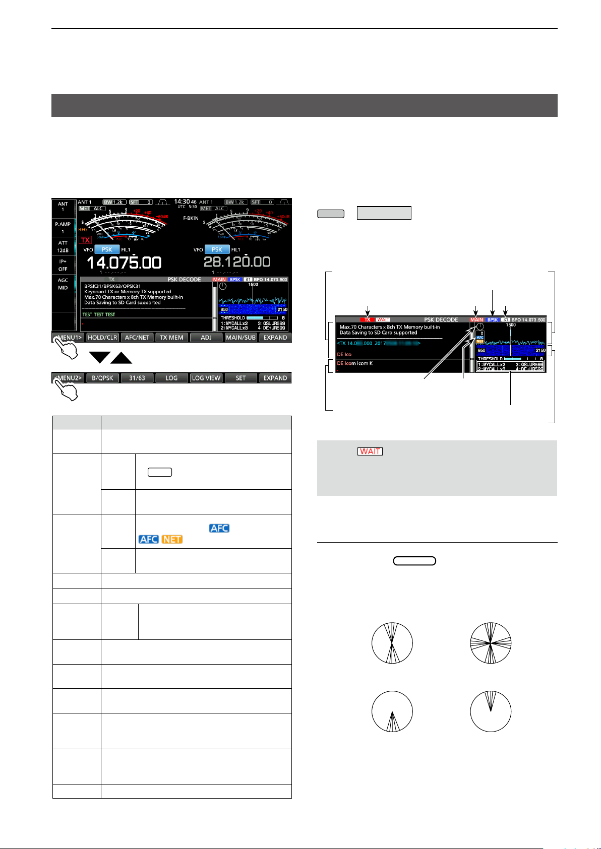
Operating PSK
A PSK encoder/decoder is built into the IC-7610. You
can connect a USB keyboard to the transceiver and
operate PSK without a PC.
If you would rather use your PSK software, refer to its
manual.
PSK DECODE screen (MENU1)
PSK DECODE screen (MENU2)
Function Action
<MENU1>
<MENU2>
HOLD/
CLR
Selects the Function menus.
Turns the Hold function ON or OFF.
Touch
Touch
1 sec.
• “
Clears the displayed characters.
” is displayed and the
current screen freezes..
D Displaying the PSK DECODE screen
With the built-in demodulator and decoder, received
PSK signals are displayed on the PSK DECODE
screen.
L The decode screen for the PSK mode slightly
differs from that of the RTTY mode.
» DECODE
PSK DECODE screen
Decoded characters
B/QPSK mode
Transmitting
Transmitting contents
(Example: PT1)
Selected band (MAIN)
Vector tuning
indicator
AFC/NET
PSK memory title
NOTE: “ ” appears next to the transmitting
status indicator on the PSK DECODE screen while
buffering. If this appears, stop typing for a while and
try transmitting again.
FFT scope
BPSK 31/36
Waterfall display
Touch
AFC/NET
Touch
1 sec.
TX MEM Displays the PSK MEMORY screen.
ADJ Enters the threshold level adjustment mode.
DEF
MAIN/
SUB
B/QPSK
31/63
LOG
LOG
VIEW
SET Displays the PSK DECODE SET screen.
Touch
1 sec
Toggles between the Main and Sub bands.
Toggles between the BPSK and QPSK
modes.
Toggles between the BPSK31 and BPSK63
modes.
Displays the PSK DECODE LOG set screen.
• Starts/Stops saving a log le, or sets the le
Displays the PSK DECODE LOG VIEW
screen.
• You can view the saved log contents.
Toggles between (AFC:ON),
(AFC/NET: ON) or OFF.
Adds the offset frequency to the
operating frequency.
Sets the threshold levels to their defaults.
L This key is displayed after
touching [ADJ].
type.
Vector tuning indicator
The Vector tuning indicator is displayed when tuning PSK
signals by rotating
Indication example
25
.
Page 30
2. ADVANCED OPERATIONS
MAIN DIAL
MENU
MENU
MENU
Operating PSK (Continued)
D PSK decoding
You can ne tune the PSK signal using the Vector
tuning indicator and waterfall display.
• When a PSK signal is received, the vertical line
appears on the waterfall display.
• Tune the vertical line to the center of the waterfall
display.
• The signal is properly tuned when the radiated lines
in the vector tuning indicator narrow, as shown on
the previous page.
L If the two or more signals are in the band, slowly
rotate
1500 Hz tone.
L You can change the PSK tone frequency for
receiving, in the following item.
» SET > Function > PSK Tone Frequency
to tune the displayed signal to the
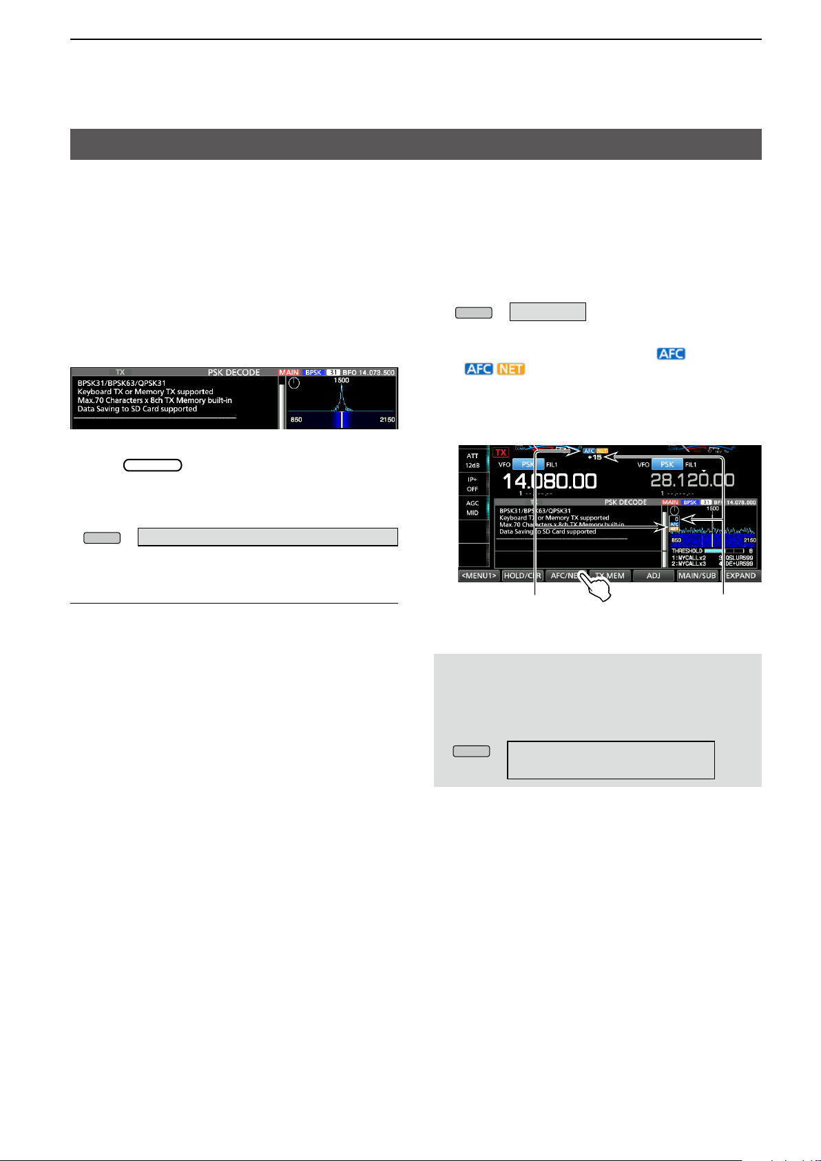
D AFC/NET function
The IC-7610 has an AFC (Auto Frequency Control)
function which automatically tunes the PSK signal. It
also has a NET function that transmits the PSK signal
tuned using the AFC function.
1. Display the PSK DECODE screen.
» DECODE
2. Touch [AFC/NET].
• Touching this key toggles between (AFC:ON),
(AFC/NET: ON) or OFF (no icon).
• While the offset between the operating frequency and
the PSK signal is displayed, touching [AFC/NET] for
1 second adds the offset frequency to the operating
frequency.
About the QPSK mode operation
The QPSK (Quadrature Phase Shift Keying)
mode has error correction capability to provide
better decoding than the BPSK mode in marginal
conditions. However, more accurate tuning is
required, due to the tight phase margin of QPSK.
L If the received signal is not properly demodulated,
try selecting the PSK-R mode.
• In the QPSK mode, the phase shift direction must
be the same on both the transmit and receive
sides.
• To receive the reverse direction signal, select the
PSK-R mode to match the phase shift direction to
the transmit side.
AFC, NET icons Frequency offset
(Example: 15 Hz)
NOTE:
• The AFC function may not tune the signal properly
when a weak PSK signal is received.
• The AFC tuning range is set to ±15 Hz by default.
You can select set to ±8 Hz in the following item.
» DECODE > <MENU2> > SET >
AFC Range
26
Page 31

2. ADVANCED OPERATIONS
MENU
EXIT
MENU
Operating PSK (Continued)
D Transmitting a PSK memory content
You can transmit the preset characters on the PSK
MEMORY screen.
L You can edit the characters by touching [EDIT] on the
PSK MEMORY screen.
1. Display the PSK DECODE screen in the PSK
mode.
» DECODE
L The PSK mode screen slightly differs from the
RTTY mode.
2. Touch [TX MEM].
Memory
PT1 MYCALLx2
PT2 MYCALLx3
PT3 QSLUR599
PT4 DE+UR599
PT5 73 GL SK
PT6 CQ CQ CQ
PT7 RIG&ANT
PT8 EQUIP.
Title Preset characters by default
↵DE Icom Icom K↵
↵DE Icom Icom Icom K↵
↵QSL UR 599 599 BK↵
↵QSL DE Icom Icom UR 599 599
BK↵
↵73 GL SK↵
↵CQ CQ CQ DE Icom Icom Icom
K↵
↵My transceiver is IC
Antenna is a 3 element triband
yagi.↵
↵My PSK equipment is internal
modulator & demodulator of the
IC-7610.↵
-
7610 &
3. Touch an PSK memory between [PT1] and [PT8]
to transmit.
(Example: PT1)
Lights red
Transmitting contents are displayed.
• The TX status indicator lights red and the Po meter
swings.
L To cancel the transmission and to return to the PSK
DECODE screen, push
LAfter transmitting, automatically returns to receive.
.
When a keyboard is connected:
• You can transmit the preset contents in the PSK
memory (PT1 ~ PT8) by pushing [F1] ~ [F8] on the
USB keyboard.
After transmitting the preset contents, you can
directly enter a PSK message on the keyboard,
and then push [F12] to transmit.
To return to receive, push [F12] again.
• If the Auto TX/RX function is set to “OFF” or
“AUTO RX” (p. 28), you can display the preset
contents on the PSK DECODE screen, and then
transmit it by pushing [F12] on the keyboard.
• You can transmit the preset contents in the PSK
memory (PT1 ~ PT8) from an external device by
setting the “External Keypad,” and then connecting
an external keypad to [MIC] or [EXT KEYPAD] on
the IC-7610.
» SET > Connectors > External Keypad
27
Page 32

2. ADVANCED OPERATIONS
MENU
EXIT
Operating PSK (Continued)
D Setting the PSK Automatic TX/RX
You can set to automatically transmit the PSK
memory contents or to automatically return to receive
after transmitting for each memory (PT1 ~ PT8).
Selection
OFF
AUTO TX/RX
AUTO TX
AUTO RX
The selected memory contents are
displayed on the PSK DECODE screen.
Push [F12] on the keyboard to transmit
the selected memory and push [F12]
again to return to receive.
Automatically transmits the selected
memory and returns to receive.
Automatically transmits the selected
memory, and then returns to receive by
pushing [F12] on the keyboard.
The selected memory contents are
displayed on the PSK DECODE screen.
Push [F12] on the keyboard to transmit
the selected memory, and then it
automatically returns to receive after
transmitting.
Action
1. Display the PSK DECODE screen.
» DECODE
L The PSK mode screen slightly differs from the
RTTY mode.
5. Touch to select an option.
(Example: AUTO TX)
2. Touch [TX MEM].
3. Touch [EDIT ] .
4. Touch the setting memory’s option.
(Example: PT1’s AUTO TX/RX)
6. To exit the PSK DECODE screen, push
several times.
28
Page 33

2. ADVANCED OPERATIONS
QUICK
EXIT
MENU
Operating PSK (Continued)
D Editing a PSK memory
You can edit the characters in the PSK memories. You
can save and transmit 8 PSK memories for often-used
RTTY messages.
Each PSK memory contains up to 70 characters.
1. Display the PSK MEMORY editing screen.
» DECODE > TX MEM > EDIT
2. Touch the editing memory content.
(Example: PT2)
4. Enter the new characters, and then touch [ENT]
to save.
L You can also push
, and then touch
“Edit Memory Content.”
3. To clear a character, touch [←] or [→] to move the
cursor, then touch [CLR].
5. To exit the PSK DECODE screen, push
several times.
29
Page 34

2. ADVANCED OPERATIONS
MENU
EXIT
Operating PSK (Continued)
D Turning ON the PSK log
Turn ON the PSK decode log to save your TX and RX
PSK operating record onto an SD card.
L You can select the data format type in the “Log Set”
item on the PSK DECODE LOG screen.
LThe log is saved even while “HOLD” is ON.
1. Display the PSK DECODE LOG screen.
» DECODE > <MENU2> > LOG
2. Touch “Decode Log.”
Log Set > File Type (Default: Text)
Set the le type to save a log onto an SD card to
“Text” or “HTML.”
L You cannot change the le type while logging.
TIP: How to reset to the default setting
Touching the item or its option for 1 second displays the
Quick menu, and then touch “Default” to reset to the
default setting.
3. Select “ON.”
4. Push
• “●” is displayed on the PSK DECODE screen while
the PSK log is ON.
.
5. To turn OFF the PSK log, select “OFF” in step 3.
30
Page 35

2. ADVANCED OPERATIONS
MENU
EXIT
MENU
EXIT
Operating PSK (Continued)
D Viewing the PSK log contents
You can view the saved PSK log contents.
1. Insert the SD card that the PSK log is saved.
2. Display the PSK DECODE LOG VIEW screen.
» DECODE > <MENU1> > LOG VIEW
3. Touch the log file to view.
L The le with “●” is logging. You cannot view this log’s
contents.
4. To exit the PSK DECODE LOG VIEW screen,
push
several times.
D PSK Decode Log set
This mode is for the log le type, time stamp setting,
and other PSK settings.
1. Display the PSK DECODE SET screen.
» DECODE > <MENU1> > SET
2. Select an item to set.
(Example: FFT Scope Averaging)
3. Select a setting option.
(Example: 2)
L See the next page for details on the setting
items and their options.
Checking the le information and deleting a le
1. Touch the log file that you want to check or
delete for 1 second.
2. Select an item from “File Information,” “Delete”
and “Delete All.”
• File Information: Displays the le name, size and
logged date.
• Delete: Deletes the selected log le.
• Delete All: Deletes all log les.
4. To exit the PSK DECODE SET screen, push
several times.
TIP: How to reset to the default setting
Touching the item or its option for 1 second displays the
Quick menu, and then touch “Default” to reset to the
default setting.
31
Page 36

2. ADVANCED OPERATIONS
MULTI
MULTI
Operating PSK (Continued)
D PSK Decode log set (Continued)
FFT Scope Averaging (Default: OFF)
Set the FFT scope waveform averaging function to
between 2 and 4, or to OFF.
L Use the default or smaller FFT scope waveform number
for tuning.
FFT Scope Waveform Color
(Default: R: 51, G: 153, B: 255)
Set the color of the FFT scope waveform.
L Touch and select the R (Red), G (Green) or B (Blue)
scale, and then rotate
between 0 and 255.
LThe color is displayed in the box above the RGB scale.
to adjust the ratio to
AFC Range (Default: ±15 Hz)
Selects the AFC (Automatic Frequency Control)
function’s operating range from ±15 Hz and ±8 Hz.
L The AFC function may not tune the signal properly when
a weak PSK signal is received.
Time Stamp (Default: ON)
Select whether or not display the time stamp (date,
transmit and receive time) on the PSK DECODE
screen, and add it in the log.
• OFF: Does not display or add the time stamp.
• ON: Displays and adds the time stamp in the log.
Time Stamp (Frequency) (Default: ON)
Select whether or not to display the frequency
information on the PSK DECODE screen and to save
it as a log when “Time Stamp” is ON.
• OFF: Does not display or save as a log.
• ON: Displays and saves as a log.
Font Color (Receive) (Default: R: 128, G: 255, B: 128)
Font Color (Transmit) (Default: R: 255, G: 106, B: 106)
Font Color (Time Stamp) (Default: R: 0, G: 155, B: 189)
Font Color (TX Buffer) (Default: R: 255, G: 255, B: 255)
Set the text font color for received, transmitting, time
stamp characters.
L Touch and select the R (Red), G (Green) or B (Blue)
scale, and then rotate
between 0 and 255.
LThe color is displayed in the box above the RGB scale.
to adjust the ratio to
Time Stamp (Time) (Default: Local)
Select whether or not to display the log on the PSK
DECODE screen and to save it, with the local time or
with the UTC time when “Time Stamp” is ON.
• Local: Displays and saves in the local time.
• UTC: Displays and saves in UTC time.
32
Page 37

2. ADVANCED OPERATIONS
SPLIT
MENU
MENU
MAIN DIAL
FM repeater operation
A repeater receives your radio’s signals and
simultaneously retransmits them on a different
frequency to provide a greater communication range.
When using a repeater, the transmit frequency shifts
from the receive frequency by an offset amount. You
can access a repeater using the split function.
1. Set the operating frequency in the FM mode.
(Example: 29.650.00 MHz)
2. Hold down
• Turns ON the Quick Split function.
• Turns the Tone function ON and “TONE” is displayed.
• The TX indicator and the repeater’s receive frequency
are displayed on the Sub band .
for 1 second.
Repeater Tone ON
Repeater Tone ON
D Setting the repeater tone frequency
Some repeaters require a subaudible tone in order to
be accessed. Subaudible tones are superimposed on
your signal, and must be set rst.
Do the following steps to set the tone frequency.
1. Select the FM mode.
2. Touch [TONE] for 1 second.
3. Rotate
frequency.
to select the subaudible tone
Split function ON
L You can set the frequency offset for the HF band.
Repeater’s receive
frequency
» SET > Function > SPLIT >
FM SPLIT Offset (HF)
LYou can set the frequency offset for the 50 MHz.
» SET > Function > SPLIT >
FM SPLIT Offset (50M)
Resets the tone frequency
to the default.
• Selectable tone frequencies
67.0 88.5 114.8 151.4 177.3 203.5 250.3
69.3 91.5 118.8 156.7 179.9 206.5 254.1
71.9 94.8 123.0 159.8 183.5 210.7
74.4 97.4 127.3 162.2 186.2 218.1
77.0 100.0 131.8 165.5 189.9 225.7
79.7 103.5 136.5 167.9 192.8 229.1
82.5 107.2 141.3 171.3 196.6 233.6
85.4 110.9 146.2 173.8 199.5 241.8
(Continued on the next page)
33
Page 38

2. ADVANCED OPERATIONS
EXIT
XFC
XFC
XFC
XFC
FM repeater operation (Continued)
D Setting the repeater tone frequency (Continued)
Checking the repeater tone frequency
You can check the tone frequency by receiving the
repeater’s input frequency using the tone scan. To
receive the input signals, the transceiver detects
the subaudible tone frequency using the tone scan
function.
1. Touch [T-SCAN].
• The scan starts, and then stops when a matching
tone frequency the same as the repeater is received.
Blinks while scanning
2. To close the TONE FREQUENCY screen, push
.
D Checking the repeater input signal
You can check whether you can directly receive
another station’s transmit signal or not, by listening to
the repeater input frequency.
L While receiving, hold down
repeater input frequency.
L While listening, the TX/RX indicator lights green,
and then the Noise Reduction and Notch Filter
settings are cancelled.
Quick Split function ON
While holding
down
.
to listen the
Release
.
Another station’s transmit frequency
34
Page 39

2. ADVANCED OPERATIONS
EXIT
MAIN DIAL
Tone squelch operation
The Tone squelch opens only when you receive a
signal that includes a matching subaudible tone in the
FM mode. You can silently wait for calls from other
stations using the same tone.
When you transmit, the tone frequency is
superimposed on your own signal.
1. Set the operating frequency in the FM mode.
(Example: 29.550.00 MHz)
2. Touch [TONE] several times to select “TSQL.”
L Touching [TONE] changes between “TONE,” “TSQL”
and “OFF.”
3. Touch [TONE] for 1 second.
Checking another station’s tone frequency
You can check another station’s tone frequency by
tone scanning while the station is transmitting.
1. Touch [T-SCAN].
• The scan starts, and then stops when the tone
frequency as another station is received.
Blinks while scanning
2. To close the TONE FREQUENCY screen, push
.
4. Rotate
• Selectable tone frequencies
67.0 88.5 114.8 151.4 177.3 203.5 250.3
69.3 91.5 118.8 156.7 179.9 206.5 254.1
71.9 94.8 123.0 159.8 183.5 210.7
74.4 97.4 127.3 162.2 186.2 218.1
77.0 100.0 131.8 165.5 189.9 225.7
79.7 103.5 136.5 167.9 192.8 229.1
82.5 107.2 141.3 171.3 196.6 233.6
85.4 110.9 146.2 173.8 199.5 241.8
to select the tone frequency.
Touch for 1 second to
reset to the default.
35
Page 40

2. ADVANCED OPERATIONS
170 Hz
2125 Hz
2295 Hz
MAIN DIAL
MENU
MENU
EXIT
MAIN DIAL
Data mode (AFSK) operation
You can operate in a data mode using AFSK (Audio
Frequency Shift Keying).
L When operating RTTY in the AFSK mode, PSK31
or JT65 with a PC application software, refer to the
software’s instruction manual.
1. Connect a PC or other device to the transceiver.
2. Set the operating band and data operating mode.
(Example: 50 MHz band, FM-D1)
Data mode
3. Refer to your application software manual for
setting and communication details.
L When operating in the SSB data mode, adjust the
device’s output level to be within the ALC zone.
TIP: The carrier point is displayed when operating AFSK
in the SSB data mode.
See the illustration below for a tone-pair example in the
LSB mode.
Transverter operation
You can use the Transverter function as an exciter for
a transverter.
D Transverter setting example
This is an example of operating a 144 MHz band
transverter using the IC-7610’s 50 MHz band.
1. Connect the 144 MHz band transverter’s RF
output to [X-VERTER].
2. Set the operating band and mode.
(Example: 50 MHz band (MAIN), SSB)
3. Rotate
(Example: 50.000.00)
4. Turn ON the “Transverter function” in the
following item (Example: 94 MHz).
»
SET > Function > Transverter Function
5. Set the “Transverter Offset” in the following item.
»
SET > Function > Transverter Offset
• The offset frequency (94.000) set in this item is added
to the operating frequency (50.000.00) to operate the
144 MHz band transverter.
L The rst digit “1” is not displayed.
Therefore, 144 MHz is displayed as “44.000.000.”
to set the frequency.
Carrier point
MarkSpace
(displayed frequency)
6. Push
Displayed while the Transverter function is ON.
7. Rotate
several times to close the SET screen.
144.000.00 MHz 145.000.00 MHz
to set the frequency.
36
Page 41

2. ADVANCED OPERATIONS
About the 5 MHz frequency band operation (USA version only)
Operation on the 5 MHz frequency band is allowed
on 5 discrete frequencies and you must adhere to the
following:
• The USB, USB Data, PSK, and CW modes.
• Maximum of 100 watts ERP (Effective Radiated
Power)
• Maximum 2.8 kHz bandwidth
It is your responsibility to set all controls so that
transmission in this frequency band meets the
stringent conditions under which amateur operations
may use these frequencies.
TIP: We recommend that you save these
frequencies, modes and lter settings into memory
channels, for easy recall.
NOTE: To assist you in operating within the rules specied
by the FCC, transmission is illegal on any frequencies
other than the ve shown in the tables below.
For the USB and USB data modes:
The FCC species center frequencies on the 5 MHz
frequency band. However, the transceiver displays
carrier frequency. Therefore, tune the transceiver
to 1.5 kHz below the specied FCC channel center
frequency.
Transceiver displayed
frequency
5.33050 MHz 5.33200 MHz
5.34650 MHz 5.34800 MHz
5.35700 MHz 5.35850 MHz
5.37150 MHz 5.37300 MHz
5.40350 MHz 5.40500 MHz
For the CW and PSK modes:
The transceiver displays the center frequency.
Therefore, tune the transceiver to the specied FCC
channel frequency when you operate in these modes.
Transceiver displayed
frequency
5.33200 MHz 5.33200 MHz
5.34800 MHz 5.34800 MHz
5.35850 MHz 5.35850 MHz
5.37300 MHz 5.37300 MHz
5.40500 MHz 5.40500 MHz
FCC channel center
frequency
FCC channel center
frequency
37
Page 42

3. ADVANCED SCOPE OPERATION
EXIT
MENU
MENU
EXIT
Spectrum Scope screen
D Setting the Center Mode span
Displays signals around the operating frequency
within the selected span. The operating frequency is
always displayed in the center of the screen.
1. Display the SPECTRUM SCOPE screen.
» SCOPE
2. Touch [CENT/FIX] to select the Center mode.
L Touch [CENT/FIX] to toggle between the Center and
Fixed modes.
3. Touch [SPAN] several times until the desired
scope span is selected.
• Selectable span:
±2.5, 5.0, 10, 25, 50, 100, 250 and 500 kHz
Example: Setting for ±2.5 kHz span
–2.5 kHz +2.5 kHz
Center mode
is selected
D Setting the Fixed Mode range
Displays signals within a specied frequency range.
The selected frequency band activity can easily be
observed using this mode.
Three Fixed Edge bands can be set for each amateur
frequency band covered by the transceiver.
1. Display the SPECTRUM SCOPE screen.
» SCOPE
2. Touch [CENT/FIX] to select the Fixed mode.
L Touch [CENT/FIX] to toggle between the Center and
Fixed modes.
3. Touch [EDGE] several times until the desired
Fixed Edge frequency band is selected.
L The xed Edge frequencies are settable (p. 41).
Example: 14.000 MHz
Fixed mode
is selected
Example:
14.350 MHz
4. To close the SPECTRUM SCOPE screen,
push
.
Example: 14.000 MHz
“>>” shows that the receive frequency is out
of the xed Edge frequency.
L When the operating frequency moves outside
the upper or lower Edge frequency, “<<” or “>>”
is displayed in the upper side corners of the
SPECTRUM SCOPE screen.
<<: The frequency is outside the lower edge.
>>: The frequency is outside the higher edge.
L When the frequency moves further away,
“Out of Range” is displayed.
Example: 14.100 MHz
4. To close the SPECTRUM SCOPE screen,
push
.
36
Page 43

3. ADVANCED SCOPE OPERATION
MENU
EXIT
MENU
MENU
MENU
EXIT
Spectrum Scope screen (Continued)
D Directly selecting a frequency
By touching or clicking on the FFT scope zone or the
waterfall zone on the SPECTRUM SCOPE screen,
you can directly tune your frequency on the displayed
area of the band.
1. Display the SPECTRUM SCOPE screen.
» SCOPE
2. Touch the signal spectrum on the FFT scope
zone or the waterfall zone or click on a signal.
(Example: in the Center mode)
3. If you touch the FFT scope zone or the
waterfall zone, the touched area is zoomed in.
Touch the signal in
the zoomed area.
D Displaying the Dual Scope screen
The transceiver has a Dual scope mode that
simultaneously displays the Main and Sub band
scopes during Dualwatch operation.
1. Display the SPECTRUM SCOPE screen.
» SCOPE
2. Touch [DUAL].
L Touching [DUAL] toggles between Dual scope and
Single scope.
The selected scope is
framed in orange.
If you click on a signal, your frequency is tuned
to the signal frequency.
Click on the frequency
Your frequency is tuned to the signal frequency.
InformationL
• While right-clicking on the screen, the frequency
where the cursor is located is displayed.
• By right-clicking and dragging the cursor, the
frequency changes. Release to return to the
originally selected frequency.
• By clicking and dragging with the cursor, the
frequency changes to that where the cursor is
released.
4. To exit the SPECTRUM SCOPE screen,
push
.
The Sub band scope
is selected.
L Touching or clicking the scope that is not framed in
orange selects the Main band scope or Sub band scope.
L You can select the scope display type in the Dual
Scope Type item.
»
SCOPE > EXPD/SET > Dual Scope Type
Example: “Side by Side”
L You can also set the Dual Scope Auto Select item
not to change the operating band (Main/Sub) when
the frequency is touched or clicked.
» SCOPE > EXPD/SET >
Dual Scope Auto Select
3. To exit the SPECTRUM SCOPE screen,
37
push
.
Page 44

3. ADVANCED SCOPE OPERATION
MENU
EXIT
MENU
MAIN DIAL
EXIT
Spectrum Scope screen (Continued)
D Adjusting the sweep speed
Select the sweep speed to change the FFT scope
refresh speed and the waterfall speed.
L To change only the waterfall speed, select “Slow,”
“Mid,” or “Fast” in the Waterfall Speed.
1. Display the SPECTRUM SCOPE screen.
» SCOPE
2. Touch [<MENU1>] to display Menu 2.
3. Touch [SPEED] several times until the desired
sweep speed is selected.
• Selectable speeds: FAST, MID, or SLOW
L“,” “,” or “” indicates FAST, MID, or SLOW.
L A popup window is displayed in the center of the
SPECTRUM SCOPE screen and displays the
selected sweep speed for 1 second.
“,” “,” or “” is displayed.
Displays the sweep speed.
D Adjusting the Reference level
When monitoring a weak signal that is buried in the
noise oor, or monitoring a strong signal but some
stronger signals are nearby, adjusting the Reference
level of the screen helps you to see these signals.
• Even if this setting is changed, it does not affect the
input signal level.
• When you adjust the Reference level, the signal
strength for the waterfall also appears to change.
1. Display the SPECTRUM SCOPE screen.
» SCOPE
2. Touch [<MENU1>] to display the Menu 2.
3. To u c h [ R E F ] .
Displayed
4. To exit the SPECTRUM SCOPE screen,
push
.
4. Rotate
• Adjustable range: –30.0 dB ~ +10.0 dB
LYou can reset to ±0.0 dB by touching [DEF].
to adjust the level.
5. To exit the SPECTRUM SCOPE screen, push
.
Difference in the spectrum
Reference level
(+10.0 dB)
+10.0dB
±0.0dB
–30.0dB
(–30.0 dB)
L If you adjust this setting to a positive level, all
signal levels appear stronger.
Or, if you adjust to a negative level, all signal
levels appear weaker.
38
Page 45

3. ADVANCED SCOPE OPERATION
MENU
MAIN DIAL
EXIT
SCOPE SET screen
This Set screen is used to set the waveform color,
Scope range for the Fixed mode, and so on.
1. Display the SPECTRUM SCOPE screen.
» SCOPE
2. Touch [EXPD/SET] for 1 second.
3. Rotate
to scroll through the items, and
then touch the item you want to set.
(Example: Max Hold)
4. Touch an option to set.
LSee the column to the right for details on the items.
Scope during Tx (CENTER TYPE) (Default: ON)
Set the TX signal display to ON or OFF.
Max Hold (Default: 10s Hold)
Select the peak level holding function.
• OFF: Turns OFF the peak level holding
function.
• 10s Hold: Holds the peak spectrum for 10 seconds.
• ON: Continuously holds the peak spectrum.
CENTER Type Display (Default: Filter Center)
Select the center frequency of the SPECTRUM
SCOPE screen. (Only in the Center mode)
• Filter Center: Displays the selected lter’s center
frequency in the center of the
SPECTRUM SCOPE screen.
• Carrier Point Center:
Displays the carrier point frequency
of the selected operating mode in the
center of the SPECTRUM SCOPE
screen.
• Carrier Point Center (Abs. Freq.):
In addition to the carrier point center
setting above, the actual frequency is
displayed at the bottom of the scope.
L Abs. Freq. : Absolute Frequency
5. To exit the SCOPE SET screen, push
TIP: How to reset to the default setting
.
Touching the item or its option for 1 second
displays the Quick menu, and then touch “Default”
to reset the item/option to its default setting.
Marker Position (Fix Type) (Default: Carrier Point)
Select the marker position on the SPECTRUM
SCOPE screen. (Only in the Fixed mode)
• Filter Center: Displays the Marker on the selected
lter’s center frequency.
• Carrier Point: Displays the Marker on the carrier
point frequency of the selected
operating mode.
Averaging (Default: OFF)
Set the FFT scope waveform averaging function to
between 2 and 4, or OFF.
• OFF: The FFT scope screen refreshes on
each sweep time. This setting displays
the critical spectrum view.
• 2, 3, 4: The FFT scope screen averages 2 to 4
sweeps to smoothly display the spectrum.
Waveform Type (Default: Fill)
Select the outline waveform display for the FFT
scope screen.
• Fill: The waveform is drawn only in color.
• Fill+Line: The waveform is drawn in color with an
outline.
39
Page 46

3. ADVANCED SCOPE OPERATION
MULTI
MULTI
MULTI
SCOPE SET screen (Continued)
Waveform Color (Current)
(Default: (R) 217 (G) 241 (B) 247)
Set the waveform color for the currently received
signals.
L Touch and select the R (Red), G (Green) or B
(Blue) scale, and then rotate
to adjust the
level from 0 to 255.
L The color is displayed in the box above the RGB
scale.
Waveform Color (Line) (Default: (R) 70 (G) 30 (B) 0)
Set the waveform outline color for the currently
received signals.
L Touch and select the R (Red), G (Green) or B
(Blue) scale, and then rotate
to adjust the
level from 0 to 255.
L The color is displayed in the box above the RGB
scale.
Waveform Color (Max Hold)
(Default: (R) 58 (G) 110 (B) 147)
Set the waveform color for the received signals
maximum level.
L Touch and select the R (Red), G (Green) or B
(Blue) scale, and then rotate
to adjust the
level from 0 to 255.
L The color is displayed in the box above the RGB
scale.
Waterfall Display (Default: ON)
Turn the Water fall display ON or OFF for the normal
scope or Mini scope screens.
L On the Expanded scope screen, the Waterfall is
always displayed.
• OFF: Turns OFF the Waterfall display.
• ON: Turns ON the Waterfall display.
Waterfall Peak Color Level (Default: Grid 10)
Select the signal level that the Waterfall displays a
peak color.
Higher signal levels are Red, Yellow, Green, Lightblue, Blue and Black, in that order.
• Selection: Grid 1 ~ Grid 10
Waterfall Marker Auto-hide (Default: ON)
Set the Waterfall Marker Auto-hide function to ON or
OFF.
• OFF: The marker in the Waterfall zone stays ON.
• ON: The marker in the Waterfall zone is hidden
2 seconds after it stops in place.
Dual Scope Type (Default: Over/Under)
When the Dual scope is selected, select the Main and
Sub scope layout.
• Over/Under: Displays the Main scope over the
Sub scope.
• Side by Side: Displays the Main and Sub scopes
side by side.
Dual Scope Auto Select (Default: ON)
When the Dual scope is selected, by selecting the
band (MAIN or SUB) simultaneously switches the
Main or Sub scope.
• OFF: The Main scope and Sub scope are not
switched by selecting the Main band or Sub
band.
• ON: The Main scope and Sub scope are
switched by selecting the Main band or Sub
band.
Waterfall Speed (Default: Mid)
Select the Waterfall speed.
• Slow: Sets the waterfall speed to Slow.
• Mid: Sets the waterfall speed to Mid.
• Fast: Sets the waterfall speed to Fast.
Waterfall Size (Expand Screen) (Default: Mid)
Select the Waterfall height in the Expand scope screen.
• Small: The same height as the Normal scope
screen, only the FFT scope expands.
• Mid: The Waterfall height expands at the same
ratio as the FFT scope.
• Large: Only the Waterfall height expands.
Continued on the next page
40
Page 47

3. ADVANCED SCOPE OPERATION
MULTI
SCOPE SET screen (Continued)
Fixed Edges
0.03 – 1.60 (Default: No.1 0.500–1.500 MHz)
(Default: No.2 0.500–1.500 MHz)
(Default: No.3 0.500–1.500 MHz)
Set the Upper and Lower Edge frequencies for the
Fixed mode. Three edges are assigned to each band.
• Settable range: 0.030 ~ 1.600 MHz
L Touch to select the upper and lower edge
frequency, and then rotate
pad to edit the frequency.
or touch the key
1.60 – 2.00 (Default: No.1 1.800–2.000 MHz)
(Default: No.2 1.800–1.830 MHz)
(Default: No.3 1.900–1.930 MHz)
• Settable range: 1.600 ~ 2.000 MHz
20.00 – 22.00 (Default: No.1 21.000–21.450 MHz)
(Default: No.2 21.000–21.150 MHz)
(Default: No.3 21.150–21.450 MHz)
• Settable range: 20.000 ~ 22.000 MHz
22.00 – 26.00 (Default: No.1 24.890–24.990 MHz)
(Default: No.2 24.890–24.930 MHz)
(Default: No.3 24.930–24.990 MHz)
• Settable range: 22.000 ~ 26.000 MHz
26.00 – 30.00 (Default: No.1 28.000–29.000 MHz)
(Default: No.2 28.000–28.200 MHz)
(Default: No.3 28.200–29.000 MHz)
• Settable range: 26.000 ~ 30.000 MHz
30.00 – 45.00 (Default: No.1 30.000–31.000 MHz)
(Default: No.2 30.000–31.000 MHz)
(Default: No.3 30.000–31.000 MHz)
• Settable range: 30.000 ~ 45.000 MHz
45.00 – 60.00 (Default: No.1 50.000–51.000 MHz)
(Default: No.2 50.000–50.100 MHz)
(Default: No.3 50.100–50.300 MHz)
• Settable range: 45.000 ~ 60.000 MHz
2.00 – 6.00 (Default: No.1 3.500–4.000 MHz)
(Default: No.2 3.500–3.575 MHz)
(Default: No.3 3.750–3.850 MHz)
• Settable range: 2.000 ~ 6.000 MHz
6.00 – 8.00 (Default: No.1 7.000–7.300 MHz)
(Default: No.2 7.000–7.030 MHz)
(Default: No.3 7.030–7.200 MHz)
• Settable range: 6.000 ~ 8.000 MHz
8.00 – 11.00 (Default: No.1 10.100–10.150 MHz)
(Default: No.2 10.100–10.130 MHz)
(Default: No.3 10.130–10.150 MHz)
• Settable range: 8.000 ~ 11.000 MHz
11.00 – 15.00 (Default: No.1 14.000–14.350 MHz)
(Default: No.2 14.000–14.100 MHz)
(Default: No.3 14.100–14.350 MHz)
• Settable range: 11.000 ~ 15.000 MHz
15.00 – 20.00 (Default: No.1 18.068–18.168 MHz)
(Default: No.2 18.068–18.110 MHz)
(Default: No.3 18.110–18.168 MHz)
• Settable range: 15.000 ~ 20.000 MHz
41
Page 48

4. VOICE RECORDER FUNCTIONS
REC
QUICK
MENU
REC
QUICK
MENU
MENU
REC
REC
QUICK
MENU
EXIT
Recording a QSO audio
This transceiver is equipped with a QSO recorder not
only for the receive audio, but also for the transmit
audio.
This function is useful to make a QSO record or
to conrm your QSO with a rare entity’s station or
on a DX’pedition. You can also use the function to
repeatedly send the same message.
The recorded contents are saved onto an SD card.
There are 3 ways to start recording.
z Hold down
z Push
z Push
L The recorded audio is saved in the “Voice” folder on
the SD card.
for 1 second.
and select “REC Start.”
and touch [RECORD].
TIP: About the icons
• While recording, “●” is displayed
under the clock readout and the SD
card indicator next to the SD card
slot blinks blue.
• While pausing, “
〓” is displayed.
D Using the [REC] key
z Hold down
L To stop recording, hold down
again.
L You can change the recorder settings on the
RECORDER SET screen (p. 47).
for 1 second to start recording.
for 1 second
D Using the [QUICK] key
1. Push
2. Touch [<<REC Start>>] to start recording.
.
D Using the MENU screen
1. Display the QSO RECORDER screen.
» RECORD
2. Touch “<<REC Start>>” to start recording.
• “Recording Started” is displayed for 1 second.
When the PTT Automatic Recording function,
“PTT Auto REC” is set to ON in RECORDER SET,
the recording automatically starts when you start
transmitting.
» RECORD > Recorder Set >
PTT Auto REC
NOTE:
• To record a QSO, an SD card (user supplied) is required.
• If your SD card does not have an “IC-7610” folder, back
up any data on the SD card, insert it in the transceivers
card slot and then format it using the built-in format
function.
• Once the recording starts, recording will restart after the
transceiver is turned OFF and ON again.
• The recording continues until you touch <<REC Stop>>
or the free space on the SD card has run out.
• When the recording le’s content becomes 2 GB, the
transceiver continues to record, but to a new le.
3. To stop recording, touch “<<REC Stop>>.”
L The “<<REC Stop>> is displayed while recording
instead of “<<REC Start>>.”
4. To close the QSO RECORDER screen,
push
.
42
Page 49

4. VOICE RECORDER FUNCTIONS
MENU
EXIT
Playing back a QSO audio
You can playback the recorded QSO audio.
1. Insert the SD card in which the recorded audio is
saved.
2. Display the PLAY FILES screen.
» RECORD > Play Files
3. Select the folder that the file you want to playback
is saved.
4. Select the file to play back.
• Starts a playback.
Operating frequency, operating
mode, of the Main and Sub bands.
Recording start
time and date
Play back
icon
Play back
time
process
The TX/RX status
of the recorded
audio.
The number of le
Total timePlay back
L Playback continues to the next le, and stops when
the last le in the folder is played back.
5. To close the PLAY FILES screen, push
several times.
Play the
previous le
Rewind Forward
Pause/
Playback
Play the
next le
43
Page 50

4. VOICE RECORDER FUNCTIONS
yyyymmdd
VoiceTx
Playing back a recorded audio on a PC
You can also playback the voice memory data on a
PC.
L The recorded information (frequency, date, and so on) is
not displayed.
1. Insert the SD card into your PC.
LOCK
SD card
SD
Memory card
reader
2. Open the “Voice” folder.
3. Open the folder where the file you want to
playback is saved.
L The folders are titled based on the recorded date.
(yyyymmdd)
IC-7610
Capture
PC
4. Double-click file that you want to play back.
• The audio starts playing back.
LThe les are titled based on the date and time
(yyyymmdd_hhmmss.wav).
(Example: 20171001_120255.wav)
NOTE:
• The operations while playing back may differ, depending
on the application. Refer to the application’s instruction
manual for details.
• When the le does not playback, after double-clicking
the le, download an appropriate software.
(Example: Windows Media
®
Player)
Decode Psk
RttySetting
Voice
yyyymmdd
44
Page 51

4. VOICE RECORDER FUNCTIONS
MENU
EXIT
MENU
EXIT
Checking the folder information and le information
You can check the folder name, size, and saved
date or recorded le’s operating frequency, operating
mode, date, and so on.
Checking the folder information:
1. Display the PLAY FILES screen.
» RECORD > Play Files
2. Touch a folder for 1 second.
3. Touch “Folder Information.”
• The FOLDER INFORMATION screen is displayed.
Checking the le information:
1. Display the PLAY FILES screen.
» RECORD > Play Files
2. Touch a folder.
3. Touch a file to check its information for 1 second.
• The QUICK MENU is displayed.
4. Touch “File Information.”
• The FILE INFORMATION screen is displayed.
4. To close the PLAY FILES screen, push
several times.
5. To close the PLAY FILES screen, push
several times.
45
Page 52

4. VOICE RECORDER FUNCTIONS
MENU
EXIT
MENU
EXIT
Deleting les
1. Display the PLAY FILES screen.
» RECORD > Play Files
2. Select the folder that the file you want to delete is
saved.
3. Touch the file that you want to delete for 1
second.
• The QUICK MENU is displayed.
Deleting folders
1. Display the PLAY FILES screen.
» RECORD > Play Files
2. Touch the folder you want to delete for 1 second.
• The QUICK MENU is displayed.
3. Touch “ D e l e te.”
L If you want to delete all folders, touch “Delete
All Folders.”
• “Delete Folder?” is displayed.
4. Touch [YES].
• The folder is deleted and returns to the previous
screen.
4. To u c h “ D e le t e.”
L If you want to delete all les in the selected
folder, touch “Delete All.”
• “Delete File?” is displayed.
5. Touch [YES].
• The le is deleted and returns to the previous screen.
6. To close the PLAY FILES screen, push
several times.
5. To close the PLAY FILES screen, push
several times.
46
Page 53

4. VOICE RECORDER FUNCTIONS
MENU
RECORDER SET screen
You can change the recorder settings on this screen.
» RECORD > Recorder Set
REC Mode (Default: TX&RX)
Selects the recording mode to record a QSO audio.
• TX&RX: Records both the transmit and receive
audio.
• RX Only: Records only the received audio.
TX REC Audio (Default: Direct)
Selects the recording audio to transmit.
• Direct: Records the microphone audio.
• Monitor: Records the TX monitor audio.
RX REC Condition (Default: Squelch Auto)
Selects the recording condition for receive.
• Always: Records even if no signal is received.
• Squelch Auto: Records only when the squelch
opens.
(The recording will be paused when
the squelch closes while recording.)
File Split (Default: ON)
Turns the File Split function ON or OFF.
• OFF: The audio is continuously recorded into
the le even if you switch between transmit
and receive or the squelch status changes
between open and closed.
When the recording le’s size becomes
2 GB, the transceiver continues to record, but
to a new le.
• ON: While recording, and if you switch between
transmit and receive, or the squelch status
changes between open and closed, a new le
is automatically created in the same folder,
and the audio is saved into the new one.
PTT Auto REC (Default: OFF)
Turns the PTT Automatic Recording function ON or
OFF.
• OFF: The recording does not start, even if a signal
is transmitted.
• ON: The recording automatically starts when a
signal is transmitted.
The recording will stop when:
• 10 seconds has passed without transmission after the last
transmission.
• 10 minutes has passed with no signal after the last
transmission.
- If you receive a signal within 10 seconds after the last
transmission, the received audio is also recorded.
- If you receive another signal within 10 seconds after the
last reception, the received audio is also recorded.
• 10 minutes has past while operating with the squelch is
open in the SSB, CW, RTTY, or AM mode.
• The frequency or operating mode is changed.
• The operating method (V/M, M-CH, Band Stacking
Register, and so on) is changed.
PRE-REC for PTT Auto REC (Default: 10sec)
Selects whether or not record the audio that is
received before the PTT Automatic Recording
function is activated.
• OFF: Does not record the audio.
• 5sec/10sec/15sec:
Records the audio that is previously received
in this set period of time.
TIP: How to reset to the default setting
Touching the item or its option for 1 second displays
the Quick menu, and then touch “Default” to reset to
the default setting.
47
Page 54

4. VOICE RECORDER FUNCTIONS
MENU
EXIT
PLAYER SET screen
You can fast forward or rewind while playing back
an audio le. You can change the skip time in the
PLAYER SET screen.
1. Display the PLAYER SET screen.
» RECORD > Player Set
2. Touch “Skip Time.”
3. Touch an option. (Example: 5 seconds)
4. To close the PLAYER SET screen, push
TIP: How to reset to the default setting
Touching the item or its option for 1 second displays
the Quick menu, and then touch “Default” to reset to
the default setting.
.
48
Page 55

4. VOICE RECORDER FUNCTIONS
MENU
MULTI
REC
REC
REC
REC
PLAY
PLAY
PLAY
PLAY
Instant Replay functionINSTANT REPLAY SET screen
You can set the recording time and the playing back
time for the Instant Replay function.
L See the right column for using the Instant Replay
function.
1. Display the INSTANT REPLAY SET screen.
» RECORD > Instant Replay Set
2. Touch the setting item. (Example: REC Time)
3. Rotate
to set the recording time.
D Recording the Instant Replay
The Instant Replay function records the previous
15 seconds (default) from the time when
has
been pushed. The audio is recorded into the built-in
memory.
L You can only record once, and the memory is
overwritten by pushing
15
sec.
sec.
10
REC Time
5
sec.
again.
sec.
1
FuturePast
D Playing back the Instant Replay
After recording an audio using the Instant Replay
function, you can play back the last 5 seconds
(default)
LWhile playing back, is displayed.
from the time
sec.
15
REC Time
sec.
10
was pushed.
sec.
5
sec.
1
REC Time (Default: 15sec)
Set the recording time for the Instant Replay function
between 5 ~ 30 seconds. The audio is saved in the
built-in audio memory.
Play Time (Default: 5sec)
Set the play back time for the Instant Replay function
between 3 ~ 10 seconds.
The Instant Replay function plays back the recorded
audio in the built-in audio memory, from the last 5
seconds (default) from the time
was pushed.
TIP: How to reset to the default setting
Touching the item or its option for 1 second displays
the Quick menu, and then touch “Default” to reset to
the default setting.
Play Time
Playing back all the recorded memory
After recording an audio using the Instant Replay
function, you can also play back the entire memory
from the top, by
holding down
for 1 second.
LWhile playing back, is displayed.
REC Time
15
sec.
sec.
10
Playing all back
sec.
5
sec.
1
49
Page 56

5. VOICE TX MEMORY OPERATION
MENU
EXIT
Recording a Voice TX memory
You can record up to 8 Voice transmit memories
(T1 ~ T8) of up to one and a half minutes in each
memory, onto an SD card. To transmit a recorded
content using a Voice TX memory, rst record the
message, as described below.
L A user supplied SD card is required to use the
Voice TX memory function.
L You can also transmit the recorded content using
an external keypad.
D Recording
1. Display the VOICE TX screen in the SSB, AM, or
FM mode.
»
VOICE
2. Touch [REC/SET].
5. Touch and speak into the microphone
without holding down [PTT] to start recording.
InformationL
• You can record up to one and a half minutes in
each memory.
• The previously recorded content is overwritten.
Displays the input
audio level
Displayed while
recording
Adjust the Mic gain so that the “REC
Level” meter does not reach 80%
Touch to open the MIC
GAIN adjustment window
3. Touch “ R EC.”
• The VOICE TX RECORD screen is displayed.
4. To u c h “ ” of the TX memory.
(Example: T1)
6. Touch to stop recording.
7. To close the VOICE TX screen, push
several times.
D Playing back
z On the selected memory’s recording screen, touch
to start playing back without transmitting.
LTo stop the playback, touch .
Displayed while playing back
TIP: How to clear the recorded content
Touch the Voice memory for 1 second in step 4 to
display the Quick menu, and then touch “Clear.”
50
Page 57

5. VOICE TX MEMORY OPERATION
MENU
EXIT
Entering a Voice TX memory name
You can assign a name to the recorded Voice
memories.
1. Open the VOICE TX RECORD screen.
»
VOICE > REC/SET > REC
2. Touch the Voice TX memory to enter the name
for 1 second.
L The selected memory needs to contain a
recording.
• Opens the QUICK MENU screen.
3. Touch “Edit Name.”
• Opens the Name editing screen.
4. Enter a name, and then touch [ENT] to save.
• The editing screen closes and returns to the VOICE
TX RECORD screen.
• The entered name is displayed.
5. To close the VOICE TX RECORD screen, push
.
L The entered memory name is also displayed on the
VOICE TX screen.
51
Page 58

5. VOICE TX MEMORY OPERATION
MENU
EXIT
MENU
MENU
Transmitting a Voice memory content
You can transmit the Voice TX memory contents
once, or repeatedly. This is useful for transmitting
your call sign, contest number or name in some
contests, or repeatedly calling CQ.
D Transmitting
Transmits the prerecorded contents. (p. 50)
1. Display the VOICE TX screen.
»
VOICE
2. Touch the desired Voice TX memory key [T1] ~
[T8].
• Transmits the recorded content once.
Transmitting
The SD card indicator next to the card
slot blinks while transmitting.
When a keyboard or keypad is connected:
• You can transmit the preset contents in the Voice
TX memory (T1 ~ T8) by pushing [F1] ~ [F8] on the
keyboard.
- Pushing [F1] ~ [F8] while holding down the [Shift]
key repeatedly transmits the contents.
» SET > Connectors > Keyboard/Mouse >
Keyboard [F1]-[F8] (VOICE)
• You can transmit the contents in the Voice TX
memory (T1 ~ T8) from an external device by
setting the “External Keypad,” and then connecting
an external keypad to [MIC] or [EXT KEYPAD] on
the IC-7610.
» SET > Connectors > External Keypad >
VOICE
The transmission’s remaining time
3. To close the VOICE TX screen, push
.
52
Page 59

5. VOICE TX MEMORY OPERATION
MENU
EXIT
MENU
MENU
MAIN DIAL
MAIN DIAL
EXIT
Transmitting a Voice memory content (Continued)
D Repeatedly transmitting
1. Display the VOICE TX screen.
»
VOICE
2. Touch a Voice TX memory key [T1] ~ [T8] for 1
second.
• Repeatedly transmits the recorded content.
Transmitting
The SD card indicator located next to
the card slot blinks while transmitting.
D Adjusting the output level
Adjust the Voice TX memory level.
1. Display the VOICE TX screen.
»
VOICE
2. Touch [TX LEVEL].
3. Touch any Voice memory key other than [T4] or
[T8]. ([T1] ~ [T3] or [T5] ~ [T7])
• The transceiver automatically transmits.
L To adjust the Transmit voice level for [T4] and [T8],
reverse steps 2 and 3.
The transmission’s remaining timeRepeat icon
InformationL
• The recorded content is repeatedly transmitted for
10 minutes, unless you manually stop transmission
by touching the selected memory.
• You can set the pause interval between the
repeated transmissions in the “Repeat Time” item
on the VOICE TX SET screen. During this interval,
the transceiver returns to receive. (p. 54)
• After 10 minutes have passed, and all of the
recorded content in the memory is transmitted, the
transceiver automatically returns to receive.
• When a signal is received in the interval between
transmissions, the transceiver pauses the next
transmission until the signal disappears. However,
if the squelch is set to open, the transceiver
repeatedly transmits after the repeat interval time
expires, even signals are received.
3. To close the VOICE TX screen, push
TIP:
If the “DATA OFF MOD” is set to “ACC,” “USB” or “LAN,”
Voice TX memories can not be transmitted.
.
» SET > Connectors > MOD Input >
DATA OFF MOD
Rotate
Touch for 1 second to reset to the default setting
4. While transmitting, rotate
transmit voice level.
L Adjusting the level too high may result in over
modulation, and transmit signal distortion.
5. To close the VOICE TX screen, push
several times.
53
to adjust.
to adjust the
Page 60
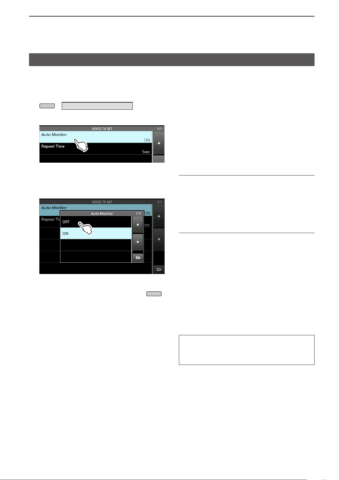
5. VOICE TX MEMORY OPERATION
MENU
EXIT
VOICE TX SET screen
This set screen is used to set the Automatic Monitor
function and the Transmit Repeat Interval.
1. Display the VOICE TX SET screen.
»
VOICE > REC/SET > SET
2. Touch the setting item. (Example: Auto Monitor)
3. Select an option. (Example: OFF)
L See to the right for details of the setting items and
their options.
4. To close the VOICE TX SET screen, push
Auto Monitor (Default: ON)
Turn the Automatic Monitor function for recorded
audio contents transmission, ON or OFF.
• ON: Automatically monitors the transmit audio
when transmitting a recorded audio.
• OFF: Monitors the transmit audio only when the
Monitor function is ON.
Repeat Time (Default: 5sec)
Set the repeat interval to repeat the voice
transmission.
The recorded content is repeatedly transmitted the at
this set interval.
• Range: 1 ~ 15 seconds
L Repeatedly transmits the recorded content for up to
.
10 minutes.
L After 10 minutes have passed, and all of the
recorded content in the memory is transmitted, the
transceiver automatically returns to receive.
TIP: How to reset to the default setting
Touching the item or its option for 1 second
displays the Quick menu, and then touch “Default”
to reset to the default setting.
54
Page 61

6. SD CARD/USB FLASH DRIVE (ADVANCED)
MENU
MENU
EXIT
Saving the setting data onto an SD card or USB ash drive
The Memory channels and the transceiver’s settings
can be saved onto an SD card or USB ash drive.
This function is convenient when:
• Copying the saved data to another IC-7610 to operate
using the same data.
• Using an IC-7610 by two or more operators with their own
individual settings.
1. Insert an SD card or USB flash drive.
2. Display the SAVE SETTING screen.
» SET > SD Card > Save Setting
» SET > USB Flash Drive > Save Setting
3. Touch “<<New File>>.”
L The le name is automatically set in the following
format: Setyyyymmdd_xx (yyyy: Year, mm: month,
dd: day, xx: serial number).
TIP: When you have updated the transceiver’s rmware,
the “Save Form” item will be added on the setting screen.
If this item is set to the earlier rmware version, the
conrmation window is displayed after step 3. To save the
data in the earlier rmware version, touch [YES].
4. To save the file with the displayed name,
touch [ENT].
L If you want to change the name, delete the name
and re-enter it, and then touch [ENT].
• “Save le?” is displayed.
5. Touch [YES].
• Saves the data settings.
6. To close the SET screen, push
several
times.
55
Page 62

6. SD CARD/USB FLASH DRIVE (ADVANCED)
MENU
MENU
Loading the saved data les onto an SD card or USB ash drive
You can load the Memory channels and transceiver’s
settings from the SD card or USB ash drive to the
transceiver.
This function is convenient when:
L The transceiver has “ALL” and “Select” loading
options to choose from.
TIP: Saving the current data is recommended before
loading other data into the transceiver. (p. 51)
1. Display the LOAD SETTING screen.
» SET > SD Card > Load Setting
» SET > USB Flash Drive > Load Setting
2. Touch the file to load.
3. Touch “Select.”
L If you want to load all the contents on the LOAD
OPTION screen, touch “ALL” and go to step 6.
5. Touch “<<Load>>.”
• “Load le?” is displayed.
6. Touch [YES].
• After the loading ends, “COMPLETED! Restart the
IC-7610.” is displayed.
L When you select “REF Adjust” in step 4, “The new
"REF Adjust" setting will be saved” is displayed.
7. Turn the OFF transceiver power, then turn it ON
again to restart the transceiver.
4. Touch the loading options.
(Example: Antenna Memory)
• “✓” is displayed left side of the selected option.
L The Set mode settings and Memory channel
contents are always loaded.
56
Page 63

6. SD CARD/USB FLASH DRIVE (ADVANCED)
MENU
MENU
EXIT
EXIT
Deleting a data le
Follow the steps below to delete the les you no
longer need on the SD card or the USB ash drive.
NOTE: Deleted data from a card or ash drive cannot be
recalled. Before deleting any data, back up the card data
onto your PC.
1. Display the SAVE SETTING screen.
» SET > SD Card > Save Setting
» SET > USB Flash Drive > Save Setting
2. Touch the file to delete for 1 second.
3. Touch “Delete.”
• “Delete le?” is displayed.
LTo delete all les, touch “Delete All.”
LTo cancel deleting, push
.
4. Touch [YES].
5. To close the SET screen, push
several
times.
Checking the le information
Touch “File Information” on the QUICK MENU to
display the le name, size and the saved date.
57
Page 64

6. SD CARD/USB FLASH DRIVE (ADVANCED)
MENU
MENU
EXIT
Displaying the SD card or USB ash drive information
You can display SD card or USB ash drive capacity,
and the time remaining for voice recording (SD card
only.)
1. Display the SD CARD or USB FLASH DRIVE
screen.
» SET > SD Card
» SET > USB Flash Drive
2. Touch “SD Card Info” or “USB Flash Drive info.”
(Example: SD Card Info)
• Displays the card or ash drive’s free space and the
capacity.
3. To close the SET screen, push
times.
several
58
Page 65

6. SD CARD/USB FLASH DRIVE (ADVANCED)
About the SD card and USB ash drive’s folders
You can easily restore data with a backup le, even if
the setting data in the SD card is accidentally deleted.
D The SD card folder
IC-7610
Capture
Decode Psk
Voice
VoiceTx
D USB ash drive folder
IC-7610
Capture
Setting
RttySetting
yyyymmdd
yyyymmdd
The folder in the SD card contains the following.
The USB ash drive contains the IC-7610 folder,
Capture folder and the Setting folder.
z IC-7610 folder
The folders created in the IC-7610 are contained
in this folder.
z Capture folder
The captured screen data is saved in the ‘png’ or
‘bmp’ format.
z Decode folder
The RTTY and PSK decode log folders are
created.
z PSK folder
The transmitted or received PSK decode log data
is saved in the ‘txt’ or ‛html’ format.
z RTTY folder
The transmitted or received RTTY decode log
data is saved in the ‘txt’ or ‛html’ format.
z Setting folder
The transceiver’s setting data is saved in the ‘dat’
format.
z Voice folder
The recorded QSO audio date folders are
created.
z yyyymmdd folder
Recorded audio les are saved in the ‘wav’
format.
The folder name is automatically created in
the following format: yyyymmdd (yyyy:Year,
mm:month, dd:day)
z VoiceTx folder
Recorded voice audio data for the Voice TX
function is saved in the ‘wav’ format.
59
Page 66

7. MEMORY OPERATION
MAIN DIAL
QUICK
MULTI
MULTI
EXIT
MENU
Memory channels
The Memory mode enables you to quickly select
often-used frequencies, modes and other parameters.
You can change the operating frequency, mode and
so on while operating in the Memory mode.
L You can temporarily tune all the memory channel
frequencies by rotating
Memory
channel
Regular memory channels.
1 frequency, 1 mode, 1 lter, memory name,
1 ~ 99
P1/P2
tone settings (including tone frequencies
for repeater and tone squelch) and select
memory scan setting in each memory
channel.
Scan Edge memory channels.
1 frequency, and 1 mode and 1 lter in
each memory channel as scan edges for
programmed scans.
Displayed
.
Selecting a Memory channel
1. Select the Main band or Sub band. (Example:
Main band)
2. Push
on the Quick menu.
3. Touch [MEMORY] to select the Memory mode.
4. Select the Memory channel.
Rotating
Rotate
channel you want to use. (Example: 2)
To close the VFO/Memory screen, push
, and then touch “VFO/MEMORY”
Memory mode
(Example: Memory channel 1)
to select a channel:
until you select the Memory
.
Selecting a channel on the MEMORY screen:
Display the MEMORY screen, and then touch to
select a Memory channel. (Example: 2)
• The channel is selected and automatically closes the
MEMORY screen.
» MEMORY
60
Page 67

7. MEMORY OPERATION
QUICK
MULTI
QUICK
EXIT
QUICK
Entering memory channel contents
The operating frequency, operating mode, IF lter
bandwidth, and so on can be entered to each
memory channel. (p. 60)
NOTE: New content you enter will overwrite any
content already in the selected memory.
1. Select the Main band or Sub band.
(Example: Main band)
2. Push
s
elect the VFO mode.
, and then touch “VFO/MEMORY” to
3. Set the frequency, operating mode, and other
parameters you want to save in memory.
4. Rotate
to select the Memory channel to
enter the contents set in step 3. (Example: 2)
L You cannot select the channel number when the Mini
scope screen, expanded screen or dual screen is
displayed.
L If “ - - . - - - . - - ” is displayed next to the selected
memory channel number, it is a blank channel,
meaning that no contents are entered in that channel.
The channel is blank.
5. Push
, and then touch “VFO/MEMORY.”
6. Touch [MW] for 1 second.
• The contents are entered in the selected Memory
channel.
The entered contents are displayed.
L To enter another channel with the same
operating mode and settings, but on a different
frequency, repeat steps 4 ~ 6 after changing the
frequency.
7. To close the VFO/MEMORY screen, push
To edit the Memory channel contents:
1. Select the Memory channel to edit.
2. Change the frequency and other parameters in
the Memory mode.
3. Push
, and then touch “VFO/MEMORY.”
4. Touch [MW] for 1 second to overwrite onto the
selected Memory channel.
.
61
Page 68

7. MEMORY OPERATION
MULTI
EXIT
MULTI
MENU
MULTI
EXIT
Copying the Memory channel contents
You can copy a Memory channel contents to the VFO or another memory channel.
D Copying to the VFO
1. Select the Main band or Sub band.
(Example: Main band)
2. Select the Memory mode.
3. Rotate
copied. (Example: Memory channel 3)
The selected channel to be copied.
VFO mode contents before copying: 14.130.00 USB
4. Touch [M→VFO] for 1 second.
• The copied contents are entered in the VFO mode.
to select the channel to be
D Copying to the other Memory channel
1. Select the Main band or Sub band.
(Example: Main band)
2. Select the Memory mode.
3. Rotate
copied. (Example: Memory channel 3)
Select the channel to be copied
4. Display the MEMORY screen.
» MEMORY
5. Rotate
copied contents to. (Example: Memory channel 5)
6. Touch of the selected channel.
to select the channel to be
to select the channel to write the
VFO mode contents after copying: 14.200.00 USB
5. Touch [VFO] to select the VFO mode.
6. To close the VFO/MEMORY screen, push
7. Touch “Memory Write.”
.
• “Write Memory?” is displayed.
8. Touch [YES].
• The copied channel contents are entered to the
selected channel.
9. To close the MEMORY screen, push
62
.
Page 69

7. MEMORY OPERATION
MENU
MULTI
EXIT
MENU
Entering a memory name
Except for the blank channels, you can assign a
name to all memory channels, including scan edges.
The names will be displayed along with the frequency,
mode and lter number.
1. Display the MEMORY screen.
» MEMORY
2. Rotate
to select the channel to enter a
name. (Example: Memory channel 2)
3. Touch of the selected channel.
4. Touch “Edit Name.”
5. Enter a name, and then touch [ENT].
(Example: #1DX Spot)
LRefer to page 14 for character entry.
Memory name
6. To close the MEMORY screen, push
Memory name
L The Memory name is not displayed when the Mini
scope screen or expanded screen is displayed.
L You can also select not to display the Memory name
on the standby screen.
» SET > Display > Memory Name
.
63
Page 70

7. MEMORY OPERATION
MULTI
EXIT
QUICK
Clearing a memory channel
You can clear a no-longer-used memory channel and
reset it as a blank channel, except for the program
channels (P1 and P2).
1. Select the Main band or Sub band.
(Example: Main band)
2. Select the Memory mode.
3. Rotate
(Example: Memory channel 3)
4. Touch [M-CLR] for 1 second.
to select the channel to clear.
The memory channel to clear
About the MEMORY screen
wq e r
t
q Memory channel number
Displays the memory channel number.
L “P1” or “P2” is displayed for the Scan Edge
memory channels.
Memory select icon
Touch this icon to set the select number “1,”
“2,” “3” or OFF. See page 69 for the Select
Memory scan.
L You can also touch the icon for 1 second to display
the SELECT ALL CLEAR screen, and then select the
item to reset the select number.
Cleared
5. To close the VFO/MEMORY screen, push
w Frequency/Operating mode/IF lter
Displays the entered frequency, selected operating
mode, and the IF lter.
e Memory name
Displays the memory name, if entered.
LSee the previous for details.
r Memory menu
Touch to display the MEMORY MENU.
L You can select between “Edit Name,” “Memory Write”
and “Memory Clear”.
.
t [▲] and [▼]
Touch to scroll through the Memory channels, 6
channels at a time.
About the QUICK MENU
While selecting a memory channel with memory
contents, push
to display the QUICK MENU,
where you can select “SELECT,” “Edit Name,” “Memory
Write,” “Memory Clear,” and “SELECT All Clear.”
64
Page 71

7. MEMORY OPERATION
MENU
QUICK
MP-W
MP-R
MP-R
MP-R
MENU
Memo Pad
There are 5 Memo Pads as the default to save
frequencies and operating modes for easy write and
recall. You can increase the Memo Pads to 10 in
“Memopad Numbers. ”
»
SET > Function > Memo Pad Quantity
L The Memo Pads are separate from memory
channels.
D Saving the displayed contents into a
Memo Pad
1. Select the Main band or Sub band.
(Example: Main band)
2. Push
Quick menu.
3. Touch [VFO] to select the VFO mode.
4. Push
• A beep sounds.
LTo save additional Pads, repeat steps 1 to 4.
L When you save up to the set number of Memo Pads
in “Memo Pad Quantity,” the oldest Memo Pad is
automatically cleared to make room for the new
Memo Pad.
, then touch “VFO/MEMORY” in the
to save the displayed content.
Memo Pads are convenient when you want to
temporarily memorize a frequency and operating
mode, such as when you nd a DX station in a
pile-up, or when the desired station is busy for a long
time and you want to temporarily search for other
stations.
Use Memo Pads instead of relying on hastily
scribbled notes that are easily misplaced.
D Calling up the Memo Pads
1. Select the Main band or Sub band.
(Example: Main band)
2. Push
L Pushing
the Memo Pads.
About the MEMO PAD screen
The MEMO PAD screen displays the saved contents
in a list, in which you can select or delete the saved
contents.
To display the MEMO PAD screen,
z Push
MENU screen.
»
.
scrolls through the contents saved in
for 1 second or touch [MPAD] on the
MPAD
Temporary Pad
L If you change the frequency or operating mode
called up from Memo Pads, the contents are
automatically updated in a temporary Pad.
Key Action
▲/▼
DEL
DEL ALL
EXPAND
65
Scrolls through the list.
Touch
1 second
Touch
1 second
Select to display the MEMO PAD list in a
normal or larger size screen.
Deletes the selected Memo Pad.
Deletes all the Memo Pads.
Page 72

8. SCANS
AF RF/SQL
Scan types
Scan types Operation (Scan function is enabled in the Main band)
VFO SCAN
Programmed scan
Fine Programmed scan
MEMORY SCAN
Memory scan
Select Memory scan
F SCAN
∂
Fine ∂F scan
Used to detect a signal by automatically changing the frequency in the VFO mode.
Repeatedly scans between two Scan Edge frequencies.
The edge frequencies are programmable, and are preset in P1 and P2 as the default. (pp. 61, 64)
If the squelch opens while scanning, the tuning step changes to 10 Hz. This reduces the
scan speed, but the transceiver keeps scanning.
Used to detect a signal by automatically scanning the memories in the Memory mode.
Repeatedly scans all entered Memory channels.
Repeatedly scans all or one of 3 select Memory channels.
Repeatedly scans within the ∂F span area.
The scan starts from the center frequency. (p. 71)
If the squelch opens while ∂F spanning, the tuning step changes to 10 Hz. This
reduces the scan speed, but the transceiver keeps scanning.
Preparation
D Squelch status
Scans work with the Main band’s squelch status.
Be sure to adjust the squelch level according to your
operating environment.
L Normally, set
disappears, and the TX/RX indicator goes OFF.
When the scan starts with the squelch open:
• For a Programmed scan
When the tuning step is 1 kHz or less, the scan
continues until it is manually stopped— it does not
pause* even if signals are detected.
* The scan pauses when the squelch is closed and then
opened. The scan resumes after 10 seconds has passed
when the Scan Resume function is ON. It is cancelled
when the function is OFF.
When the tuning step is 5 kHz or more, the scan
pauses on each step when the Scan Resume
function is ON. It does not pause when the function is
OFF.
• For a Memory scan
The scan pauses on each channel when the Scan
Resume function is ON. The scan does not pause
when the function is OFF.
to the point where noise
When the scan starts with the squelch closed:
The scan stops when a signal is detected, regardless
of the tuning step.
• When the Scan Resume function is ON, the scan pauses
for 10 seconds after detecting a signal, then resumes 2
seconds after the signal disappears.
66
Page 73

8. SCANS
MENU
QUICK
MENU
EXIT
SCAN screen
To display the SCAN screen, push
touch [SCAN].
Main band: VFO mode
Main band: Memory mode
L To select the VFO mode or Memory mode, push
and touch “VFO/MEMORY,” and then on the
VFO/MEMORY screen, touch [VFO] or [MEMORY].
Key Action
PROG Starts or cancels the Programmed scan.
MEMO Starts or cancels the Memory scan.
∂F Starts or cancels the ∂F scan
While Programmed scanning, touch to switch
to the Fine Programmed scan.
FINE
∂F SPAN
RECALL
SET Displays the SCAN SET screen.
SELECT
SEL No.
While ∂F scanning, touch to switch to the
Fine ∂F scan.
L In the Memory mode, this key is displayed
when a ∂F scan is started.
Touch to select the ∂F span between ±5 kHz,
±10 kHz, ±20 kHz, ±50 kHz, ±100 kHz, ±500
kHz, and ±1 MHz.
Touch
1 second
Touch
Touch
1 second
Selects the Select scan number for the Select
Memory scan.
Each time you touch [SEL No.], “1,” “2,”
“3,” and “1,2,3” are alternately displayed.
Recalls the frequency that was set
before starting the scan in the VFO
mode.
Selects a Memory channel to set
as a Select Memory channel.
“1,” “2,” “3,” and “(no icon)”
are alternately displayed.
Displays the SELECT ALL CLEAR
screen.
, and then
SCAN SET screen
1. Display the SCAN screen.
» SCAN
2. Touch [SET].
3. Touch an item to set. (Example: SCAN Speed)
4. Touch an option. (Example: Slow)
5. To close the SCAN SET screen, push
SCAN Speed (Default: Fast)
Set the desired scan speed to slow or fast.
• Slow: Scan speed is slow.
• Fast: Scan speed is fast.
SCAN Resume (Default: ON)
Set the Scan Resume function to ON or OFF.
• OFF: When a signal is detected, cancels the scan.
• ON: When a signal is detected, scan pauses for
10 seconds, then resumes.
Two seconds after the signal disappears, the
scan resumes.
TIP: How to reset to the default settings
Touching an item or its option for 1 second displays
the Quick menu, and then touch “Default” to reset
to the default setting.
.
67
Page 74

8. SCANS
Scan
Scan edge
P1 or P2
Scan edge
P2 or P1
Jump
MENU
EXIT
Programmed scan
Programmed scan and Fine Programmed scan
Repeatedly scans between two Scan Edge
frequencies.
The edge frequencies are preset in P1 and P2 as
the default.
(P1: 0.500000 MHz / P2: 29.999999 MHz)
L To change the P1 and P2 Scan Edge Memory
channels, see “Entering memory channel
contents” (p. 61) for details.
L If the same frequencies are entered into P1 and
P2, the Programmed scan does not start.
L The Fine Programmed scan is most effective in
the SSB, CW, and RTTY modes.
D Programmed scan operation
1. Select the VFO mode in the Main band.
2. Select the operating mode (example: USB),
tuning step (1 kHz).
3. Display the SCAN screen.
» SCAN
4. Touch [PROG] to start the Programmed scan.
L “PROGRAM SCAN” blinks while scanning.
L You can change the operating mode and the tuning
step while scanning.
Frequency before scanBlinks
5. Touch [FINE] to switch to the Fine Programmed
scan.
L While scanning, “FINE PROGRAM SCAN” blinks
instead of “PROGRAM SCAN.”
L Touch [FINE] again to return to the Programmed
scan.
Blinks
6. To close the SCAN screen, push
times.
68
several
Page 75

8. SCANS
MENU
EXIT
MENU
MULTI
MENU
Memory scan
Memory scan
Ch 1 Ch 2 Ch 3 Ch 4
Ch 99
Blank channels are skipepd
Ch 5
Ch 6Ch 7Ch 50Ch 98
Repeatedly scans all entered Memory channels.
Blank (not entered) Memory channels are skipped.
L If two or more Memory channels are not entered,
the Memory scan does not start.
D Memory scan operation
1. Select the Main band.
2. Display the SCAN screen.
» SCAN
3. Touch [MEMO] to start the Memory scan.
L When a signal is detected, the scan pauses
according to the “SCAN Resume” setting, and then
resumes.
LTo cancel the scan, touch [MEMO] again.
Select Memory scan
Ch 99
★1
Ch 1
★1
“★1,” “★2” and “★3” show that the channel
is specified as a Select Memory.
Ch 98
★1
Ch 2
★2
Ch 50
Ch 3
★1
Ch 7
★3
★2
Ch 4
Ch 6
★1
Ch 5
★1
(Example: Select Memory channel ★1)
Repeatedly scans all or one of 3 Select Memory
channels (★1, ★2, ★3).
L If two or more Memory channels are not
designated as Select Memory channels, the
Select Memory scan does not start.
D Setting the Select Memory channels
1. Select the Main band.
2. Display the SCAN screen.
» SCAN
3. Rotate
as the Select Memory channel. (Example: ★1)
4. Touch [SELECT] to set the selected number.
L “1,” “2,” “3,” and “(no icon)” are alternately
displayed.
to select memory channels to set
★1
Blinks Not displayed while a Memory scan.
4. To close the SCAN screen, push
“1” is set to Memory channel 3.
5. Repeat steps 3 and 4 to set more than two
.
Memory channels.
L You cannot set blank channels as Select Memory
channels.
L You can check the Select Memory channel settings
on the MEMORY screen.
» MEMORY
(Example: “1” is set to Memory channel 1 and 3)
69
Page 76

8. SCANS
MENU
EXIT
Memory scan (Continued)
D Select Memory scan operation
1. Select the Main band.
2. Display the SCAN screen.
» SCAN
3. Touch [MEMO] to start a regular Memory scan.
L When a signal is detected, the scan pauses
according to the “SCAN Resume” setting, and then
resumes.
5. Touch [SELECT] to switch to the Select Memory
scan.
L Touching [SELECT] switches between the Memory
scan and the Select Memory scan.
Blinks
Memory scan
4. While scanning, touch [SEL No.] to select the
Select Memory scan number.
L Each time you touch [SEL No.], “★1,” “★2,” “★3,”
and “★1,2,3” are alternately displayed.
★1: Channelsspeciedas★1 are scanned.
★2: Channelsspeciedas★2 are scanned.
★3: Channelsspeciedas★3 are scanned.
★1,2,3:Channelsspeciedas★1, ★2, or ★3 are
scanned.
Select the Select Memory scan
number (Example: ★1)
Blinks
Select Memory scan
6. To cancel the scan, touch [MEMO].
7. To close the SCAN screen, push
Clearing all Select Memory channel settings
.
1. Touch [SELECT] for 1 second on the SCAN
screen.
• The SELECT ALL CLEAR screen is displayed.
2. Touch the Select Memory channel setting to
cle ar.
70
Page 77

8. SCANS
MENU
EXIT
∂F scan
∂F scan and Fine ∂F scan
(Example: Span: ±10 kHz)
14.18 MHz 14.19 MHz14.17 MHz
Scan Scan
Start
Jump
CenterScan edge Scan edge
Repeatedly scans within the ∂F span area.
The scan starts from the center frequency.
LInnescan(programmedor∂F), the scan
speed decreases when the squelch opens, but
the transceiver keeps scanning. The scan tuning
step changes to 10 Hz when the squelch opens.
D ∂F scan operation
1. In the Main band, set the center frequency.
(Example: in the VFO mode)
2. Set the operating mode and the tuning step.
(Example: USB, 1 kHz)
LYou can also change these settings while scanning.
3. Display the SCAN screen.
» SCAN
4. To u c h [∂F SPAN] to select the span.
• Options: ±5 kHz, ±10 kHz, ±20 kHz, ±50 kHz,
±100 kHz, ±500 kHz, or ±1 MHz
5. Touch [∂F] to start the scan.
L When a signal is detected, the scan pauses
according to the “SCAN Resume” setting, and then
resumes.
LTo cancel the scan, touch [
L To turn the TS function to scan by the frequency step
setting, touch the 100 kHz digit on the frequency
readout.
∂F] again.
6. To switch to the Fine ∂F scan, touch [FINE].
• The scan frequency step changes to 50 Hz.
L Touching [FINE] switches between the ∂F scan and
the Fine ∂F scan.
Blinks
7. To close the SCAN screen, push
.
Blinks
The span set in step 4
The frequency
before starting the scan
71
Page 78

9. CLOCK AND TIMERS (ADVANCED)
MENU
EXIT
MENU
EXIT
NTP function
The NTP (Network Time Protocol) function
synchronizes the internal clock with the time
management server.
L To use this function, an internet connection and
default gateway settings are necessary.
D Using the NTP Time Synchronize
function
Using this function you can manually synchronize
the internal clock by accessing the time management
server.
1. Display the DATE/TIME screen.
» SET > Time Set > Date/Time
2. Touch “<<NTP TIME SYNC>>.”
• “ NTP Time Sync. Please wait...” is displayed.
• The transceiver starts accessing the NTP server
address that is set in the “NTP Server Address” item.
3. When “Time Sync completed.” is displayed, touch
[OK].
4. To close the DATE/TIME screen, push
several times.
D Using the NTP function
By turning ON the NTP function, the transceiver
automatically synchronizes the internal clock with the
time management server.
LThis function is set to ON by default.
1. Display the DATE/TIME screen.
» SET > Time Set > Date/Time
2. Touch “NTP Function.”
3. Select ON or OFF.
• When ON is selected, the transceiver starts accessing
the NTP server address that is set in the “NTP Server
Address” item.
4. To close the DATE/TIME screen, push
several times.
72
Page 79

9. CLOCK AND TIMERS (ADVANCED)
TIMER
MULTI
TIMER
TIMER
EXIT
Setting the Timers
D Setting the Sleep Timer
The Sleep Timer automatically turns OFF the
transceiver power when the set time period has
passed. You can set the timer to between 5 and 120
minutes, in 5 minute steps.
1. Push
for 1 second.
2. Touch “Sleep Timer.”
3. Rotate
to set the sleep timer.
(Example: 120 minutes)
4. Touch [SET] to save the setting and to start the
ti mer.
• The timer indicator on the
• Approximately 10 seconds before the transceiver
power turns OFF, the indicator on the key starts
blinking.
L After the transceiver turns OFF, the Sleep Timer set
in step 3 is cleared.
L To pause and resume the timer while the timer is
running, push
.
5. To close the TIMER screen, push
key turns ON.
.
73
Page 80

9. CLOCK AND TIMERS (ADVANCED)
TIMER
MULTI
QUICK
EXIT
Setting the Timers (Continued)
D Setting the Daily Timer
The Daily Timer automatically turns the transceiver
power ON or OFF on the set day and time.
LYou can set up to 5 timers.
1. Push
for 1 second.
2. Touch the timer to set (Example: 1)
3. Rotate
scroll through the setting items,
and then touch an item to select.
LEach setting items are described on the next page.
L You can reset to the default setting or cancel the
setting by pushing
.
4. After setting the items, touch “<<Set>>” to save
them.
Repeat Setting
Timer Status
Reservation Timer
Power OFF Timer
Day of the Week
Reservation Channel (MAIN/SUB)
5. To close the TIMER screen, push
.
74
Page 81

9. CLOCK AND TIMERS (ADVANCED)
QUICK
QUICK
QUICK
QUICK
QUICK
Setting the Timers (Continued)
D Daily Timer setting items
NOTE: All of the following settings are not saved
until you touch “<<Set>>.”
Timer Status (Default: OFF)
Select ON to start the Daily Timer, and select OFF to
stop the timer.
Reservation Timer (Default: 0:00)
Set the time to automatically turn ON the transceiver
power.
L To clear the setting, push
and touch
“Clear.”
Power OFF Timer (Default: --:--)
Set the time to automatically turn OFF the transceiver
power.
LToclearthesetting,rstsettheReservationTimer
time, and then push
to select “Clear.”
NOTE: When Power OFF Timer is set to an
earlier time than the Reservation Timer time, the
transceiver will not be turned OFF automatically.
To automatically turn the transceiver ON and
OFF, set Power OFF Timer to a later time than the
Reservation Timer time.
Example:
• Reservation Timer: 8:00
• Power OFF Timer: 9:30
Reservation Channel (MAIN) (Default: -- ch)
Reservation Channel (SUB) (Default: -- ch)
The Memory channel set in this item is automatically
selected when the transceiver is automatically turned
ON by the Reservation Timer, or the set time has
come while the transceiver is turned ON.
LYou cannot select a blank channel.
L To clear the setting, push
and touch
“Clear.”
Day of the Week (Default: --)
Select a day of the week to set the Daily Timer
function.
L To not to select a day, leave the item set to default,
or reset to the default by pushing
and then
touch “Clear.”
Repeat Setting (Default: OFF)
Set the Repeat Setting to ON or OFF.
When this item is set to ON, the timer is activated
every selected day of the week, or everyday if the
Day of the Week item is not set.
L To clear the setting, push
and touch
“Clear.”
<<Set>>
Touch to save all the timer settings for the selected
timer.
75
Page 82

10. ANTENNA TUNER OPERATION (ADVANCED)
MENU
Antenna switching setting when operating with Dualwatch
You can connect a Transmit/Receive antenna to
either ANT1 or ANT2 for the normal operation.
However, if you want to use separate antennas for
transmit and receive you need to set “RX-ANT,” or if
you want to add an external device, such as a lter/
pre-amplier for receive you need to set “RX-I/O.”
To change the RX-ANT Connectors Type, touch
[TYPE] on the ANTENNA screen, then select
between “Connect Receive Antenna” and “Connect
External RX Device.”
» ANTENNA > TYPE
If you switch the RX-ANT Connectors Type to the
opposite type, (to “Connect External RX Device” or to
“Connect Receive Antenna”) the previous RX-ANT (or
RX-I/O) memory settings for both the Main and Sub
bands are cleared.
The “RX-I/O” settings are limited according to the
antenna connector setting (ANT1 or ANT2), as
follows.
Example:
When both the Main and Sub bands are using the
same antenna (Example: ANT1) and the RX-ANT
Connectors Type is set to “Connect External RX
Device,” if the Main is set to RX-I/O, the Sub RX-I/O
is forcibly set (temporarily) the same as the Main
setting. Turning OFF the RX-I/O on the Sub band
clears the RX-I/O settings for both the Sub and the
Main bands.
“RX-I/O” is set to both the Main and Sub bands.
(Example: Main band=ANT1, Sub band=ANT2)
When the Main (ANT1) and Sub (ANT2) bands are
set to different antennas, if you set RX-I/O to the Main
band, and then you set RX-I/O to the Sub band, the
previous Main band setting is forcibly cleared, and
is displayed. Setting Main back to RX-/IO SUB is
forcibly cleared, and is displayed.
RX-I/O is set to ANT1. ANT2 is selected.
RX-I/O is forcibly
turned OFF.
RX-I/O is set to ANT2
The Main and Sub bands are not forcibly set or
cleared when the RX-ANT Connectors Type is set to
“Connect Receive Antenna.”
RX-I/O is set.
If you turn OFF RX-I/O on the Sub band that was
forcibly set by above operation, RX-I/O on the Main
band is also forcibly turned OFF, and is displayed.
RX-I/O is forcibly
cleared.
RX-I/O is OFF.
76
Page 83

10. ANTENNA TUNER OPERATION (ADVANCED)
MENU
MENU
Selecting the antenna connector
Set the antenna connector to “ANT1” or “ANT2,” and
turn the receive antenna connector ON or OFF.
1. Select the Main band or Sub band.
2. Select the operating band.
3. Touch [ANT] in the Multi-function key group to set
to “ANT1” or “ANT2.”
L While “ANT1” is selected, touch [ANT] for 1 second
to set the antenna that is connected to [ANT1] for
transmitting, and the antenna connected to
[RX-ANT IN] for receiving.
When not using the [RX-ANT] connector,
Set “ANT1” or “ANT2.”
L When “ANT1/R” or “ANT2/R” is selected, the
signal is switched to the [RX-ANT IN] connector,
and then reception in the [ANT1] and [ANT2] are
disconnected.
L While “ANT2” is selected, touch [ANT] for 1 second
to set the antenna that is connected to [ANT2] for
transmitting, and the antenna connected to
[RX-ANT IN] for receiving
• “” is displayed if you temporarily select an antenna
that is different from the one that is saved in
memory.
- Touch [ANT MW] for 1 second to save the temporary
selection into memory, then “” disappears.
» ANTENNA > ANT MW
• When the antenna selection mode ([ANT] SW) is
set to “Manual,” each antenna connector is selected
according to the saved settings.
» ANTENNA > [ANT] SW
77
Page 84

11. OTHER FUNCTIONS
RF Direct Sampling System
The IC-7610 employs an RF direct sampling system and has 2 completely independent and identical receiver
circuits for the Main and Sub bands from the antenna to the AF output. RF signals are directly converted to digital
data and processed in a Field Programmable Gate Array (FPGA) with Icom’s state of the SDR technology.
The RF signals are sent to the A/D converter, resulting in digital signal, then is processed by the FPGA to be
restored to an analog audio signal according to the receive mode.
This system is a leading technology marking an epoch in amateur radio.
In the Direct Sampling System, there is no local oscillator or mixer circuits that are used in ordinary super
heterodyne systems. That makes the received signal less distorted in the amplication stage, resulting a higher
image response received signal.
In the transmit circuit, since the transmit signal is generated by the FPGA regardless of the type of emission, a
pure high C/N ratio transmit signal is obtained.
ANT 1
Demodulation circuit
EXT-SP A
ANT 2
Main band
Sub band
DIGI-SEL
DIGI-SEL
BPF
BPF
D/AA/D
FPGA
EXT-SP B
A/D D/A
78
Page 85

11. OTHER FUNCTIONS
MENU
AF RF/SQL
About the RF/SQL Control
» SET > Function > RF/SQL Control
You can set the
(outer) control type in the
RF/SQL Control item in the set mode.
• Auto: While in the AM or FM mode, used only
as a squelch control.
While in the SSB, CW, RTTY, or PSK
mode, used only as an RF gain control.
• SQL: Used as only a squelch control.
LRF gain is xed at maximum sensitivity.
• RF+SQL: Used as an RF gain control, and a noise
squelch or S-meter squelch.
When using as an RF gain/squelch control
Noise squelch (FM mode)
Squelch is open
RF gain
adjustable range
is displayed
(RFG)
Minimum RF gain
S-meter squelch
adjustable range
Maximum RF gain
Maximum S-meter squelch
When using as an RF gain control
(Squelch is xed open: SSB, CW, RTTY, PSK only)
Maximum RF gain
RF gain
adjustable range
is displayed
(RFG)
Minimum
RF gain
Maximum
RF gain range
When using as a squelch control
(RF gain is xed at maximum.)
Noise squelch (FM mode)
Noise squelch
threshold
Squelch is open
S-meter squelch
threshold
S-meter squelch
adjustable range
Maximum
S-meter squelch
79
Page 86

11. OTHER FUNCTIONS
MENU
About “USB SEND/Keying”
You can control transmit, receive and CW/RTTY
keying from the PC, through the USB port.
Select the control port to be used for communication
between the IC-7610 and PC in the “USB SEND,”
“USB Keying (CW)” and “USB Keying (RTTY)” items
according to your operating needs.
» SET > Connectors > USB SEND/Keying
The IC-7610 has two virtual COM ports, A and B.
When connecting to a USB port on your PC, the ports
are virtually named as USB1 (A) and USB1 (B), and
then the transmit and receive control (USB SEND),
CW Keying, or RTTY (FSK) Keying signals from the
PC are assigned to the DTR/RTS terminals in the
virtual port.
USB SEND (Default: OFF)
USB Keying (CW) (Default: OFF)
USB Keying (RTTY) (Default: OFF)
• OFF: Turns OFF the function.
• USB1 (A) DTR: Uses the DTR terminal on USB1 (A).
• USB1 (A) RTS: Uses the RTS terminal on USB1 (A).
• USB1 (B) DTR: Uses the DTR terminal on USB1 (B).
• USB1 (B) RTS: Uses the RTS terminal on USB1 (B).
TIP: About the USB SEND/Keying items
L When you operate RTTY or CW through your PC’s USB
port and your IC-7610, you may not be able to send the
“SEND” or “Keying” signals until a few seconds after
you connect the USB cable.
L When you operate through your PC’s USB port and
the IC-7610, and connect a second transceiver to
another PC USB port, a short “SEND” or “Keying”
signal will be sent from the rst transceiver. Therefore,
we recommend that you do not connect a second
transceiver to a USB port of the same PC. Or, always
turn OFF the transceiver power before you connect a
USB cable.
USB SEND
USB Keying
(CW)
USB Keying
(RTTY)
CPU
TXD
RXD
RTS
DTR
TXD
RXD
RTS
DTR
Virtual
COM
port A
Virtual
COM
port B
USB 1 (A)
USB1
USB 1 (B)
80
Page 87

11. OTHER FUNCTIONS
MULTI
TRANSMIT
TRANSMIT
Measuring SWR
The transceiver has a high-performance SWR meter.
This meter displays a stable measurement in real
time, even if the transmit output power varies
frequently. You can measure the SWR of an antenna
itself through the internal antenna tuner.
1. Select the RTTY mode.
2. Set the frequency band for the antenna.
3. Touch the meter indicator several times to display
the SWR meter.
L You can also display the SWR on the Multi-function
meter by touching the meter indicator for 1 second.
SWR meter display
4. Select the antenna connector that the antenna
that you want to measure is connected to.
5. Push
to adjust the RF POWER to more
than 30 W in the Multi-function menu.
Before transmitting, monitor the operating
frequency to make sure you will not cause
interference to other stations on the same frequency.
6. Hold down [PTT] (or push
The best match is within this range. (1.5 or less)
) to transmit.
L If the SWR meter indicates 1.5 or less, the
antenna is matched.
L If the measured SWR is more than 1.5:1, you
need to match the antenna with the transceiver.
7. After reading the SWR, release [PTT] (or push
) to return to receive.
81
Page 88

11. OTHER FUNCTIONS
MENU
EXIT
MENU
EXIT
MENU
EXIT
Selecting the Display Type
You can select between 2 display backgrounds.
1. Display the DISPLAY screen.
» SET > Display
2. Touch “Display Type.”
3. Select the background display type from A and B.
• A: Black background (default)
• B: Blue background
4. To close the DISPLAY screen, push
.
Selecting the Display Font
You can select between 2 frequency readout fonts.
1. Display the DISPLAY screen.
» SET > Display
2. Touch “Display Font.”
3. Select the display font type from “Basic” and
“Round.”
• Basic (default)
Displaying my call sign
You can set to display your own call sign at power ON.
(Example: displaying the call sign JA3YUA)
1. Display the DISPLAY screen.
» SET > Display
2. Touch “My Call.”
3. Enter “JA3YUA,” and touch [ENT] to save.
• Round
4. To close the DISPLAY screen, push
.
4. To close the DISPLAY screen, push
.
82
Page 89

11. OTHER FUNCTIONS
POWER
MENU
MENU
NR
MULTI
QUICK
EXIT
MENU
MENU
MENU
MENU
Screen Capture function
You can capture the transceiver display onto an
SD card or a USB ash drive. Most of the screens
used in this manual are captured using this function.
However, some screens cannot be captured.
D Setting the Screen Capture function
1. Display the “Screen Capture [POWER] Switch”
screen.
» SET > Function >
Screen Capture [POWER] Switch
2. Touch “ON” to turn ON the Screen Capture
function.
3. Touch “Screen Capture Storage Media” to select
“SD Card” or “USB Flash Drive” to save the
captured screens.
» SET > Function >
Screen Capture Storage Media
4. Touch “Screen Capture File Type” to set the
screen capture file type to “PNG” or “BMP.”
» SET > Function >
Screen Capture File Type
D Capturing a screen
1. Display the screen that you want to capture.
2. Push
• “SCREEN CAPTURE Completed” is displayed.
L If the “Screen Capture Keyboard [Print Screen]” is
set to ON, push [Print Screen] on the keyboard.
.
D Viewing a captured screen
1. Display the SCREEN CAPTURE VIEW screen.
SET > SD Card > Screen Capture View
»
SET > USB Flash Drive > Screen Capture View
»
• The capture screen list is displayed.
• The latest screen capture is at the top of the list.
2. Touch the screen capture to view.
• The indicator on the
screen capture.
L You can view the next screen capture
by rotating
key blinks while viewing a
.
TIP: You can also assign the Screen Capture
function to the [Print Screen] key on the USB
keyboard.
SET > Function >
»
Screen Capture Keyboard [Print Screen]
To display the le information or delete captured
screens,
While selecting a le on the SCREEN CAPTURE
VIEW screen, push
.
3. To close the SD CARD or USB FLASH DRIVE
screen, push
several times.
83
Page 90

11. OTHER FUNCTIONS
AF RF/SQL
AF RF/SQL
TWIN PBT
RIT
TX
MENU
MENU
MULTI
EXIT
REF adjustment
You can perform a rough frequency calibration by
receiving the radio station WWV, WWVH, or other
frequency signals.
NOTE:
• The transceiver has been adjusted and tested at
the factory before being shipped out. You should
not have to recalibrate.
• Before performing a frequency calibration, you
have to set “Calibration Marker” to ON.
• Spurious signal waveforms may be displayed while
the Calibration Marker is ON.
L Before performing a frequency calibration, set the
following items as described in the table below.
Operating mode
CLR
,
USB
Decent audibility
Maximum RF gain
Reset by holding down for 1 second.
OFF (No icon)
1. Set the frequency to the standard frequency
station minus 1 kHz.
L If receiving WWV or WWVH (at 15.00000 MHz) as
your standard frequency, set the operating frequency
to 14.99900 MHz.
2. Set “Calibration Marker” to ON.
» SET > Function > Calibration Marker
3. Select the “REF Adjust” item.
» SET > Function > REF Adjust
4. Rotate
to adjust for a zero beat with the
received standard signal.
L “Zero beat” means that the exact same frequencies
are set to 2 signals, resulting in a single tone being
transmitted.
5. Set “Calibration Marker” to OFF.
6. Push
several times until the MENU screen
is closed.
84
Page 91

12. MAINTENANCE (ADVANCED)
Cleaning
DO NOT use harsh solvents such as
benzine or alcohol when cleaning,
because they will damage the
transceiver surfaces.
Replacing fuse
If a fuse blows, or the transceiver stops functioning,
nd and repair the cause of the problem. Then
replace the damaged fuse with a new, adequately
rated fuse.
L Spare fuses are supplied with the transceiver.
The fuses are installed in the DC power cable and in
the inside circuitry, to protect the transceiver.
• DC power cable fuses ................................ ATC 30 A
• Circuitry fuse ................................................ ATC 5 A
RWARNING!
• Disconnect the DC power cable from the transceiver
before replacing the fuse.
• NEVER use fuses that are not specied.
If the transceiver becomes dusty or dirty,
wipe it clean with a dry, soft cloth.
D DC power cable fuses
See the following illustration to replace the DC power
cable fuses.
ATC 30 A fuse
85
Page 92

12. MAINTENANCE (ADVANCED)
Carrying handle
Shield cover
Replacing fuse (Continued)
D Circuitry fuse
1. Unscrew 2 screws to remove the carrying handle,
if attached.
2. Remove the 10 top cover screws, then remove
the cover.
4. Replace the circuitry fuse as shown below.
CAUTION: When you remove a fuse, use longnose
pliers to protect your ngers and the fuse holders.
ATC 5 A fuse
5. Replace the removed parts.
3. Remove the 15 shield screws, then remove the
shield cover.
86
Page 93

12. MAINTENANCE (ADVANCED)
MENU
EXIT
POWER
MENU
Touch screen calibration function
When no screen action occurs, or a different function
is activated after touching the screen, the touched
point and the detected point may be different.
In that case, the Touch screen calibration function
helps to correct the touch screen sensing accuracy.
1. Display the OTHERS screen.
» Set > Others
2. Touch “Touch Screen Calibration.”
• A dot appears on the screen.
3. Touch the dot that is displayed on the screen.
• A new dot appears in another position.
Touch the displayed dot
TIP: When the touch screen is not accurate, and
you cannot access the OTHERS screen.
Do the following steps to display the “Touch Screen
Calibration” screen.
1. Turn OFF the transceiver.
2. While holding down
push
to display the “Touch Screen
and
,
Calibration” screen.
3. Repeat step 3 and 4 on the left column.
4. Touch the frequency readout or a key on the
touch screen to confirm that the touch screen is
working correctly.
4. Repeat step 3.
L When the calibration is complete, the transceiver
returns to the OTHERS screen.
87
Page 94

13. UPDATING THE FIRMWARE
MENU
General
D About updating the rmware
You can update the IC-7610’s rmware using an SD
card or a USB ash drive. Updating the rmware
adds new functions and/or improves performance
parameters.
You can download the latest rmware from the Icom
website.
http://www.icom.co.jp/world/index.html
D Checking the rmware version
Check the rmware version when you turn ON the
transceiver.
The rmware version is displayed
TIP: You can also check the rmware version on the
INFORMATION screen.
» SET > Others > Information
88
Page 95

13. UPDATING THE FIRMWARE
General (Continued)
D Preparation
Access the following URL and download the firmware
file.
http://www.icom.co.jp/world/index.html
L These instructions are based on Microsoft® Windows® 7.
1. Click [Support].
Click
2. Click the “Firmware Updates/Software
Downloads” link.
Click
3. Click the desired firmware file link in the IC-7610
group.
4. Read “Regarding this Download Service”
carefully, and then click [Agree].
Click
6. Select the location where you want to save the
firmware, and then click [Save] in the displayed
File Download dialog.
• The le starts downloading.
• The rmware and the rm utility are compressed in a
“zip” format folder. Unzip it before use.
Click
D Unzipping the rmware folder
1. Right-click the downloaded firmware folder (zip
format).
• Right-click menu is displayed.
2. Click “Extract All...”
• After unzipping, a folder is created in the same
location as the downloaded folder.
L In the “7610_*” folder, “7610_*.dat” is created.
* Represents the release number.
5. C l i c k “Save as” in the displayed File Download
dialog.
Click
Click
89
Page 96

13. UPDATING THE FIRMWARE
MENU
MENU
Updating the rmware
IMPORTANT: To update the rmware, rst format
your SD card or USB ash drive using the IC-7610.
Then copy the downloaded rmware data from your
PC into the IC-7610 folder on the card or ashdrive.
CAUTION:
NEVER turn OFF the transceiver
while updating the rmware. If you turn OFF the
transceiver, or if a power failure occurs while
updating, the transceiver rmware will be damaged
and you will have to send the transceiver back to the
nearest Icom distributor for repair. This type of repair
is out of warranty, even if the transceiver warranty
period is still valid.
TIP: BE SURE to unzip the downloaded le. See
the previous page for details.
1. Copy the downloaded firmware data into the
IC-7610 folder on an SD card or a USB flash
drive.
4. Touch “Firmware Update,” and then after you
read and agree with all the precautions, touch
[YES].
• The le selecting screen is displayed.
Copy
2. Insert the SD card or USB flash drive into the
transceiver.
3. Display the SD CARD or USB FLASH DRIVE
screen.
» SET > SD Card
» SET > USB Flash Drive
5. Touch the Firmware (Example: 7610_101).
• The nal con rmation screen is displayed.
L Carefully read all the displayed precautions.
Continued on the next page.
90
Page 97

13. UPDATING THE FIRMWARE
Updating the rmware (Continued)
6. After you read and agree with all the precautions,
touch [YES] for 1 second.
• The updating starts.
7. Follow the instructions on the transceiver screen.
L The IC-7610 reads the rmware le from the SD
card or USB ash drive and writes it to the main
CPU, sub CPU, front CPU, and FPGA.
L Downloading and loading status are displayed in the
dialogs.
8. When the update is completed, “Firmware
updating has completed.” is displayed in the
dialog.
• The IC-7610 will automatically restart.
L After the updating nishes, the operating screen is
displayed.
91
Page 98

INDEX
∂F scan ................................................................... 71
Fine ∂F scan ..................................................... 71
Operation ........................................................... 71
∂TX function ............................................................ 12
∂TX monitor function ......................................... 12
A
About the 5 MHz frequency band operation ............ 37
Auto Monitor ............................................................ 54
B
Band Edge Beep ....................................................... 5
Band Beep Edges, Entering ................................ 5
Band Edge, Inserting ........................................... 6
Deleting a Band Edge ......................................... 7
Entering a new Band Edge, ................................. 7
Band Edges Beep
Resetting all band edges to presets .................... 8
C
Calibration Marker ................................................... 84
Cleaning .................................................................. 85
Clock........................................................................ 72
Connecting
AH-740, connecting ............................................. 4
Connection
137 kHz band operation ...................................... 1
RC-28 .................................................................. 2
Connections
FSK, AFSK, PSK connections ............................. 3
CW
About the CW Reverse mode ............................ 13
Contest number menu (001 SET) ..................... 15
Count up trigger ................................................. 14
Count Up Trigger (Contest number) .................. 15
Dot/Dash Ratio .................................................. 16
Keyer memory edit menu (EDIT) ....................... 14
Keyer Repeat time ............................................. 16
Keyer set menu (CW-KEY SET) ........................ 16
Key Type ........................................................... 16
MIC Up/Down Keyer .......................................... 16
Number Style (Contest number) ........................ 15
Operating CW .................................................... 13
Paddle Polarity .................................................. 16
Present Number (Contest number) ................... 15
Rise Time .......................................................... 16
Side Tone Level ................................................. 16
Side Tone Level Limit ........................................ 16
Using the Memory Keyer function (KEYER) ...... 13
D
Data mode (AFSK) operation .................................. 36
Display Font............................................................. 82
Display Type ............................................................ 82
Drive Gain level
Adjusting the Drive Gain level ............................. 9
F
File Split ................................................................... 47
Firmware
Checking the version ......................................... 88
Updating ............................................................ 90
Firmware updating
Preparation ........................................................ 89
FM repeater
Checking the repeater input signal .................... 34
Checking the repeater tone frequency .............. 34
Setting the repeater tone frequency .................. 33
FM repeater operation ............................................. 33
FPGA ....................................................................... 78
Fuse......................................................................... 85
Circuitry ....................................................... 85, 86
DC power cable ................................................. 85
Replacing .......................................................... 85
I
Instant Replay function ............................................ 49
Playing back ...................................................... 49
Recording .......................................................... 49
INSTANT REPLAY SET screen ............................... 49
IP Plus function .......................................................... 9
M
Memo Pad ............................................................... 65
Calling up .......................................................... 65
Saving ............................................................... 65
Memory channel ...................................................... 60
Clearing ............................................................. 64
Copying contents ............................................... 62
Copying to other channel .................................. 62
Copying VFO ..................................................... 62
Entering contents .............................................. 61
Memory name ................................................... 63
MEMORY screen ............................................... 64
Selecting ............................................................ 60
Memory scan
Operation ........................................................... 69
My call sign .............................................................. 82
P
PLAYER SET screen ............................................... 48
Playing back (QSO) ................................................. 43
On a PC ............................................................. 44
Play Time ................................................................. 49
PRE-REC for PTT Auto REC ................................... 47
Programmed scan
Fine Programmed scan ..................................... 68
Operation ........................................................... 68
PSK
AFC/NET function ............................................. 26
Editing a PSK memory ...................................... 29
Operating PSK .................................................. 25
PSK DECODE screen ....................................... 25
PSK decoding .................................................... 26
QPSK mode operation ...................................... 26
Setting the PSK Automatic TX/RX function ....... 28
92
Page 99

INDEX
Transmitting a PSK memory content ................. 27
Turning ON the PSK log .................................... 30
Vector tuning indicator ....................................... 25
PSK decode log
AFC Range ........................................................ 32
FFT Scope Averaging ........................................ 32
FFT Scope Waveform Color .............................. 32
Font Color .......................................................... 32
Log File Type ..................................................... 30
PSK Decode Log setting ................................... 31
Time Stamp ....................................................... 32
Time Stamp (Frequency) ................................... 32
Time Stamp (Time) ............................................ 32
Viewing the PSK log contents ........................... 31
PTT Auto REC ......................................................... 47
R
REC Mode ............................................................... 47
RECORDER SET screen ........................................ 47
Recording (QSO) ..................................................... 42
Using the MENU screen .................................... 42
Using the [QUICK] key ...................................... 42
Using the [REC] key .......................................... 42
REC Time ................................................................ 49
REF Adjust............................................................... 84
Repeat Time ............................................................ 54
RF Control ............................................................... 79
RF Direct Sampling System .................................... 78
RTTY
Editing an RTTY memory .................................. 21
Log File Type ..................................................... 22
Operating RTTY (FSK) ...................................... 17
RTTY Automatic TX/RX function ....................... 20
RTTY Decode Log setting ................................. 23
RTTY DECODE screen ..................................... 18
RTTY decoding .................................................. 18
Transmitting an RTTY memory content ............. 19
Turning ON the RTTY log .................................. 22
Twin Peak Filter (TPF) ....................................... 18
Viewing the RTTY log contents ......................... 23
RTTY decode log
Auto CR+LF by TX ............................................ 24
Decode New Line Code .................................... 24
Decode USOS ................................................... 24
Diddle ................................................................ 24
FFT Scope Averaging ........................................ 24
FFT Scope Waveform Color .............................. 24
Font Color .......................................................... 24
Time Stamp ....................................................... 24
Time Stamp (Frequency) ................................... 24
Time Stamp (Time) ............................................ 24
TX USOS ........................................................... 24
RX REC Condition ................................................... 47
S
Scan ........................................................................ 66
Fine ∂F scan ............................................... 66, 71
Fine Programmed scan ..................................... 66
∂F scan ....................................................... 66, 71
Memory scan ............................................... 66, 69
Preparation ........................................................ 66
Programmed scan ....................................... 66, 68
Select Memory scan .................................... 66, 69
Squelch status ................................................... 66
VFO scan .......................................................... 66
SCAN Resume ........................................................ 67
SCAN screen ........................................................... 67
SCAN SET screen ................................................... 67
SCAN Speed ........................................................... 67
Scope set screen ..................................................... 39
Averaging .......................................................... 39
Center type display ............................................ 39
Dual scope auto select ...................................... 40
Dual scope type ................................................. 40
Fixed edges ....................................................... 41
Marker position .................................................. 39
Max hold ............................................................ 39
Scope during Tx ................................................ 39
Waterfall display ................................................ 40
Waterfall marker auto-hide ................................ 40
Waterfall peak color level .................................. 40
Waterfall size (expand screen) .......................... 40
Waterfall speed .................................................. 40
Waveform color (current) ................................... 40
Waveform color (line) ........................................ 40
Waveform color (max hold) ............................... 40
Waveform Type ................................................. 39
Screen Capture function .......................................... 83
SD card.................................................................... 55
Deleting ............................................................. 57
Folders .............................................................. 59
Information, displaying ...................................... 58
Loading .............................................................. 56
Saving ............................................................... 55
Select Memory scan
Operation ........................................................... 70
Setting the Select Memory channels ................. 69
Spectrum scope
Center mode, setting ......................................... 36
Directly selecting a frequency ........................... 37
Dual scope screen, displaying ........................... 37
Fixed mode range, setting ................................. 36
Reference level, adjusting ................................. 38
Sweep spee,, adjusting ..................................... 38
SQL Control ............................................................. 79
SWR ........................................................................ 81
93
Page 100

INDEX
T
Timers ...................................................................... 73
Daily timer ......................................................... 74
Daily timer setting items .................................... 75
Sleep timer ........................................................ 73
Tone squelch operation ........................................... 35
Checking another station’s tone frequency ....... 35
Touch screen calibration function ............................ 87
Tracking function ..................................................... 10
Transverter operation .............................................. 36
Transverter setting example .............................. 36
TX REC Audio ......................................................... 47
U
USB ash drive ........................................................ 55
Deleting ............................................................. 57
Folders .............................................................. 59
Information, displaying ...................................... 58
Loading .............................................................. 56
Saving ............................................................... 55
USB Keying (CW) .................................................... 80
USB Keying (RTTY) ................................................ 80
USB SEND .............................................................. 80
USB SEND/Keying .................................................. 80
V
Voice Recorder function .......................................... 42
Checking the le information ............................. 45
Checking the folder information ......................... 45
Deleting les ...................................................... 46
Deleting folders ................................................. 46
Voice TX memory
Adjusting the output level .................................. 53
Entering a name ................................................ 51
Playing back ...................................................... 50
Recording .......................................................... 50
Repeatedly transmitting ..................................... 53
Transmitting ....................................................... 52
VOICE TX SET screen ............................................ 54
VOX function ............................................................11
Adjusting the VOX function ................................11
DELAY ................................................................11
Turning ON the VOX function .............................11
VOICE DELAY ....................................................11
VOX GAIN ..........................................................11
94
 Loading...