

Page 1

OPERATING GUIDE
INTRODUCTION
1 ACCESSORIES
2 PANEL DESCRIPTION
3 BASIC OPERATION
4 ADVANCED OPERATION
VHF P25 TRANSCEIVERS
iF7010 series
iF7510 series
UHF P25 TRANSCEIVERS
iF7020 series
iF7040series
iF7520 series
iF7540
series
5 SCAN OPERATION
6 MENU SCREEN
7 APCO P25 MODE OPERATION
8 MDC 1200 SYSTEM OPERATION
9 ABOUT THE microSD CARD
10 VOICE RECORDER FUNCTIONS
11 Bluetooth® OPERATION
12 USER SETTINGS
13 OTHERS
14 OPTIONS
INDEX
Page 2

INTRODUCTION
Thank you for choosing this Icom product.
This product is designed and built with Icom’s state
of the art technology and craftsmanship. With proper
care, this product should provide you with years of
trouble-free operation.
IMPORTANT
FIRST, CAREFULLY READ PRECAUTIONS
AND INSTRUCTIONS that are provided with the
transceiver.
SAVE THIS OPERATING GUIDE— This operating
guide contains additional important operating
instructions for the following transceivers.
Portable
• IC-F7010S/IC-F7020S/IC-F7040S:
Simple key type transceivers
• IC-F7010T/IC-F7020T/IC-F7040T:
Ten-key type transceivers
Mobile
• IC-F7510/IC-F7520/IC-F7540
Icom, Icom Inc. and Icom logo are registered trademarks of
Icom Incorporated (Japan) in Japan, the United States, the
United Kingdom, Germany, France, Spain, Russia, Australia,
New Zealand, and/or other countries.
AQUAQUAKE is a trademark of Icom Incorporated.
The Bluetooth
trademarks owned by the Bluetooth SIG, Inc. and any use of
such marks by Icom Inc. is under license.
Other trademarks and trade names are those of their
respective owners.
All other products or brands are registered trademarks or
trademarks of their respective holders.
®
word mark and logos are registered
Icom is not responsible for the destruction, damage to, or
performance of any Icom or non-Icom equipment, if the
malfunction is because of:
• Force majeure, including, but not limited to, res,
earthquakes, storms, oods, lightning, other natural
disasters, disturbances, riots, war, or radioactive
contamination.
• The use of Icom transceivers with any equipment that is
not manufactured or approved by Icom.
i
Page 3

Section 1
ACCESSORIES
Supplied accessories.............................................................. 1-2
Attaching accessories............................................................. 1-3
D Flexible antenna (Portable) ............................................. 1-3
D Battery pack (Portable) ................................................... 1-3
D Belt clip (Portable) .......................................................... 1-4
D Connector cover (Portable) ............................................. 1-5
D Mounting bracket (Mobile) .............................................. 1-6
1-1
Page 4
1
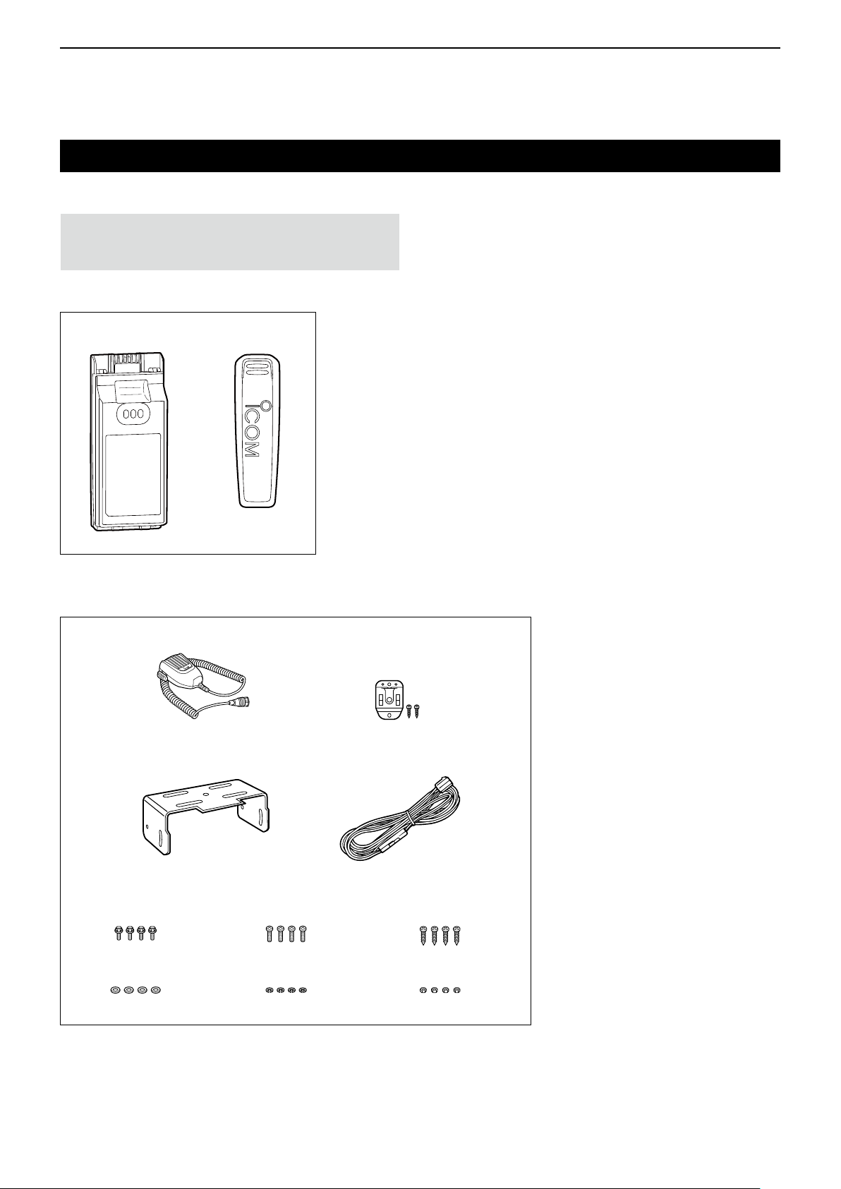
Battery pack Belt clip Connector cover
(with a screw)
ACCESSORIES
Supplied accessories
The following accessories are supplied.
NOTE: Some accessories are not supplied, or the
shape is different, depending on the transceiver
version.
z Portable type transceiver
z Mobile type transceiver
Microphone
Bracket bolts Mounting screws
(M5×12)
Flat washers Spring washers
Microphone hanger
and screw set
DC power cableMounting bracket
Self-tapping screws
(M5×16)
Nuts
1-2
Page 5
1
ACCESSORIES
Attaching accessories
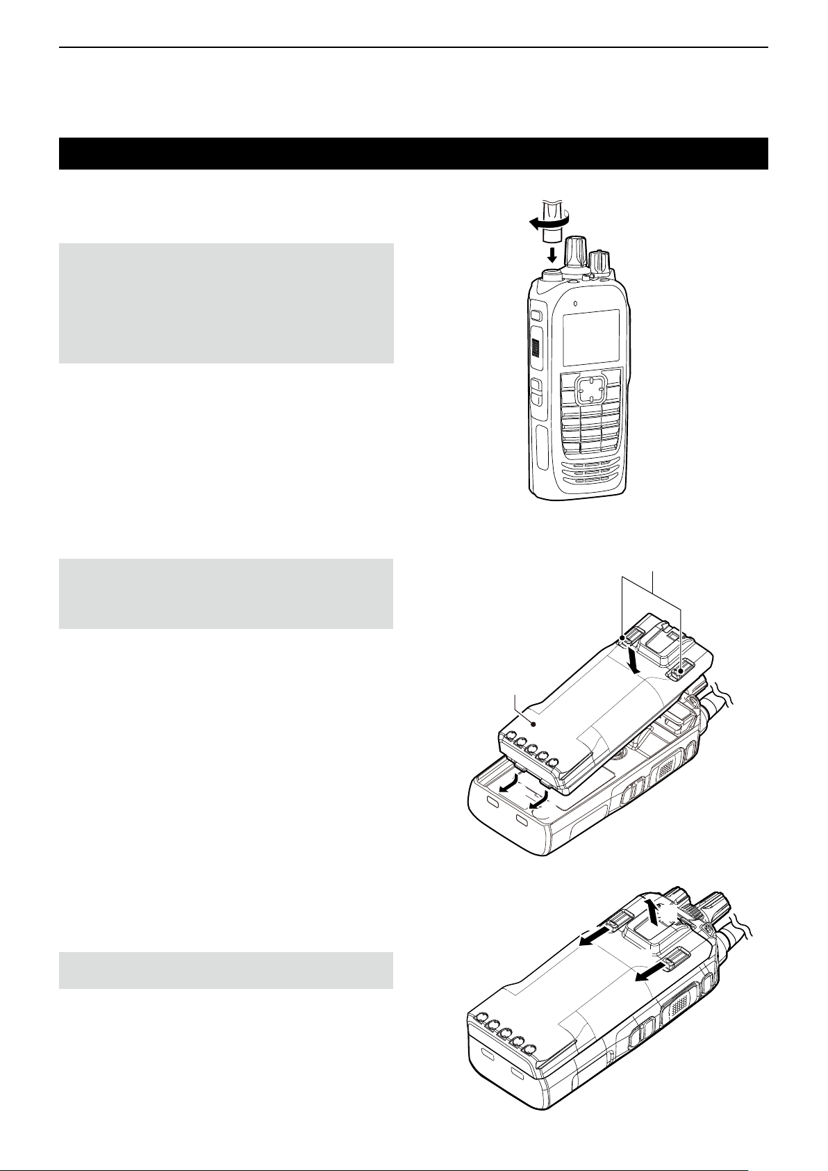
D Flexible antenna (Portable)
Connect the antenna to the antenna connector.
CAUTION:
• DO NOT carry the transceiver by holding only the
antenna.
• DO NOT connect an antenna other than those
listed in the INSTRUCTIONS.
• Transmitting without an antenna may damage the
transceiver.
D Battery pack (Portable)
CAUTION: DO NOT attach or detach the battery
pack when the transceiver is wet or soiled. This may
result in water or dust getting into the transceiver/
battery pack and may damage the transceiver.
To attach:
1. Slide the battery pack in the direction of the arrow.
(q)
2. Push the battery pack until the battery sliding
locks make a ‘click’ sound. (w)
To detach:
1. Push both battery sliding locks in the direction of
the arrow. (z)
• The battery pack is then released.
2. Lift up to detach the battery pack. (x)
To attach
Battery pack
q
To detach
q
z
Battery sliding locks
w
x
NOTE: Keep the battery pack terminals clean. It’s a
good idea to occasionally clean them.
z
1-3
Page 6
1
ACCESSORIES
Accessory attachments (Continued)
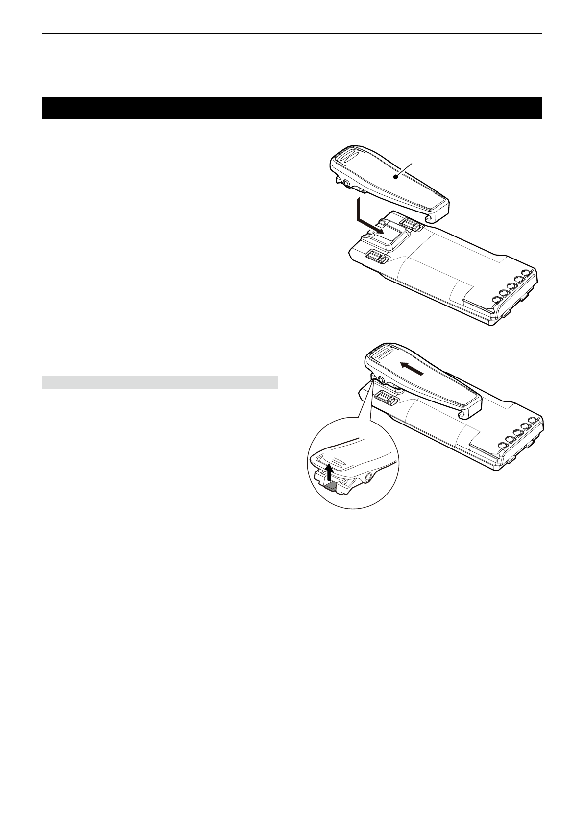
D Belt clip (Portable)
To attach:
1. Remove the battery pack from the transceiver, if it
is attached.
2. Slide the belt clip in the direction of the arrow until
the belt clip is locked and makes a ‘click’ sound.
Belt clip
To detach:
Lift the tab up (q), and slide the belt clip in the
direction of the arrow (w).
BE CAREFUL! DO NOT break your ngernail.
w
q
1-4
Page 7
1
ACCESSORIES
Accessory attachments (Continued)
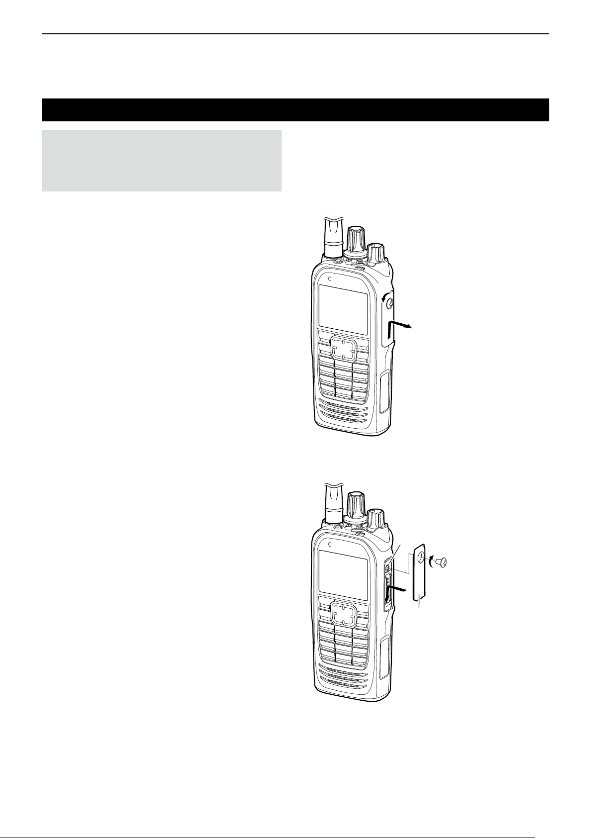
CAUTION: DO NOT detach the connector cover
when an optional equipment is not in use. Otherwise
the terminals of the multi-connector may be shorted
by a metal object, or become rusty by water
intrusion. This could damage the transceiver.
D Connector cover (Portable)
To detach:
1. Remove the screw. (z)
2. Detach the connector cover, and then connect an
optional equipment. (x)
z
x
To attach:
1. Attach the connector cover over the multiconnector. (q)
2. Tighten the screw. (w)
Multiconnector
w
q
Connector
cover
1-5
Page 8
1
ACCESSORIES
Accessory attachments (Continued)
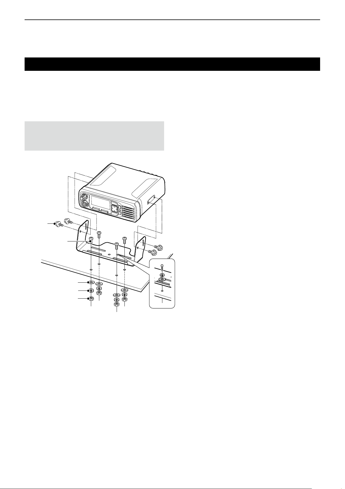
D Mounting bracket (Mobile)
Install the mounting bracket in a place where it can be
rmly attached.
L We recommend that you periodically check whether
the screws are loose or not, especially after a long
period of use.
CAUTION: DO NOT use bolts other than the
ones that are supplied with the mounting bracket.
Bolt longer than 8 mm (0.31 in) may damage the
transceiver’s internal units.
Bolt
Mounting screw
Flat washer
Spring washer
Nut
When using the
self-tapping screws
1-6
Page 9

Section 2
PANEL DESCRIPTION
Front, top and side panels (for the Portable type transceiver) 2-2
D About the transceiver types ............................................ 2-2
D About the Status indicator ............................................... 2-2
D About the Multi-connector ............................................... 2-2
D About the Software key functions ................................... 2-2
Function display (for the Portable type transceiver) ............... 2-3
D Icon Area ......................................................................... 2-3
D T ext Area .........................................................................2-4
D Key Display Area ............................................................ 2-4
Front, top and side panels (for the Mobile type transceiver) .. 2-5
D About the Status indicator ............................................... 2-5
D About the Microphone connector .................................... 2-5
D About the Software key functions ................................... 2-5
Rear panel (for the Mobile type transceiver) .......................... 2-6
Function display (for the Mobile type transceiver) .................. 2-7
D Icon Area ......................................................................... 2-7
D T ext Area .........................................................................2-8
D Key Display Area ............................................................ 2-8
Status indicator ....................................................................... 2-9
Assignable keys, keypads, and AB Switch ............................2-11
D Portable type ..................................................................2-11
D Mobile type ....................................................................2-11
Assignable Software key functions ....................................... 2-12
D For keys and keypads ................................................... 2-12
D For the AB Switch (For the Portable type transceiver) .....2-20
2-1
Page 10
2
PANEL DESCRIPTION
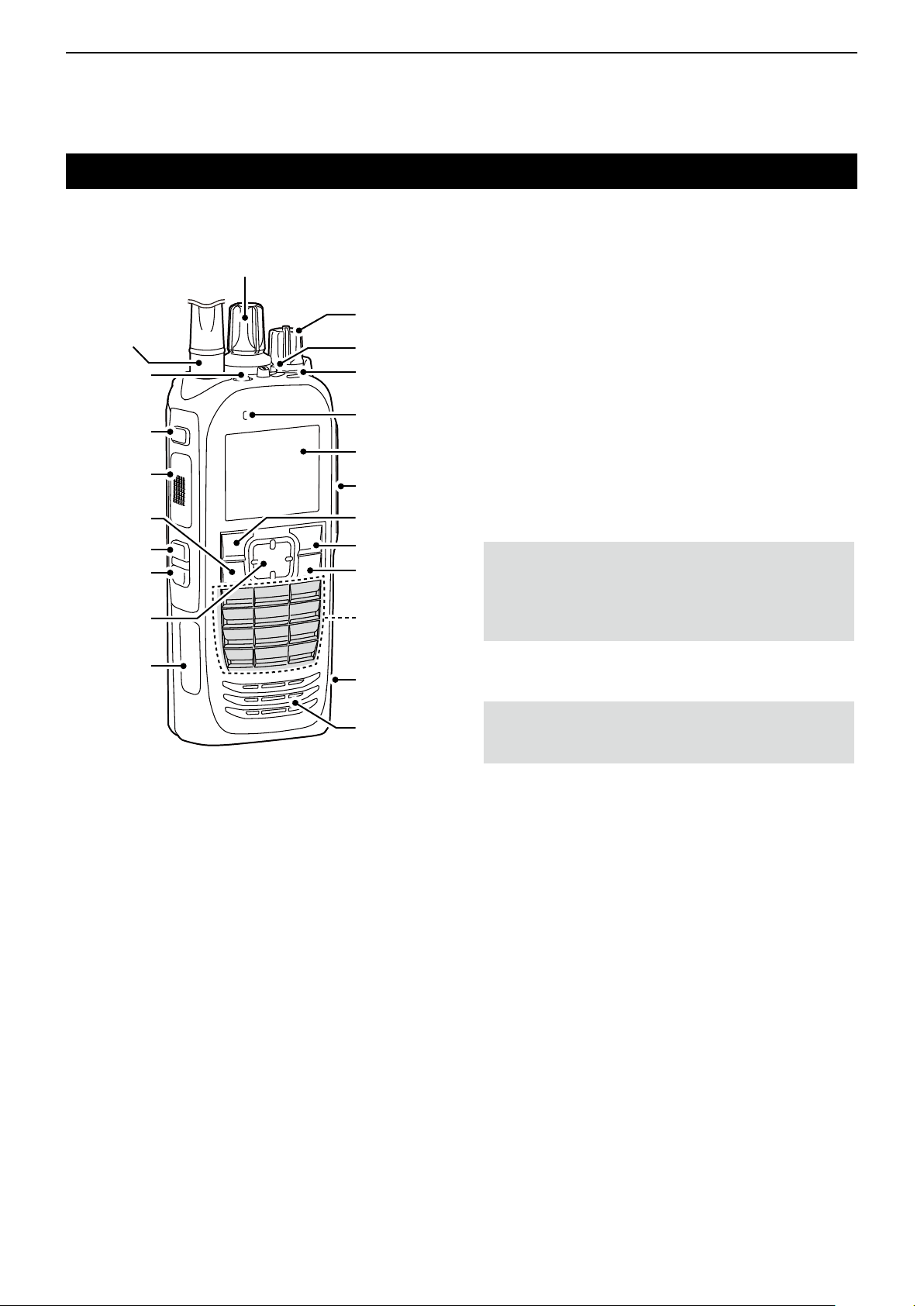
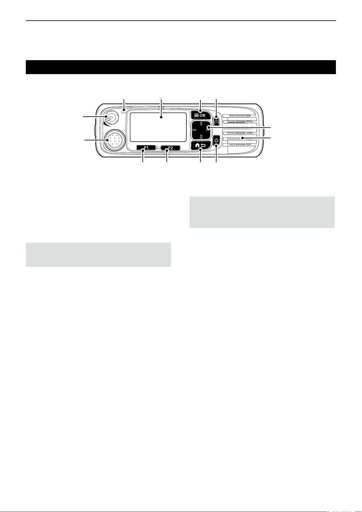
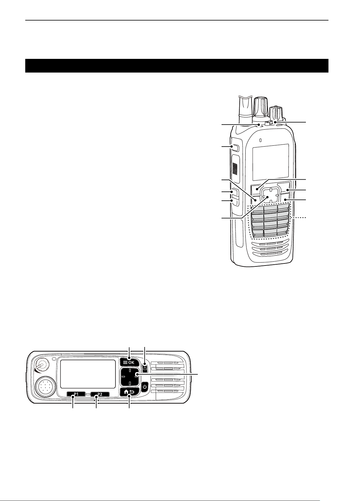
Front, top and side panels (for the Portable type transceiver)
D About the transceiver types
There are 2 types of transceivers.
IC-F7010S, IC-F7020S, IC-F7040S: Simple key types
IC-F7010T, IC-F7020T, IC-F7040T: Ten-key types
D About the Status indicator
• Lights white, then blinks red, yellow, and green when
turning ON the transceiver.
• Lights red while transmitting.
• Lights green while receiving a signal, or when the
squelch is open.
• Blinks magenta when the battery is exhausted.
D About the Multi-connector
Connects to an optional speaker microphone or
headset.
CAUTION: DO NOT use the transceiver without the
connector cover or optional device attached.
The transceiver meets IP68 requirements for dusttight and waterproof protection only when the
connector cover or the optional device is attached.
Antenna
Connector
[Emer]
[F1]
[PTT]
[OK]
[F2]
[F3]
[Up]/[Down]
[Right]/[Left]
[Selector]
[VOL]
AB Switch
Status
indicator
Microphone
Function
Display
Multiconnector
[P1]
[P2]
[Back]
Ten-Key
Pad
Micro USB
Connector
The illustration is of the Ten-key types.
microSD
Card Slot
Speaker
D About the Software key functions
NOTE: Dealers can assign the Software key
functions to the keys, keypads, and the AB Switch.
LSee page 2-11 for details.
2-2
Page 11
2
PANEL DESCRIPTION
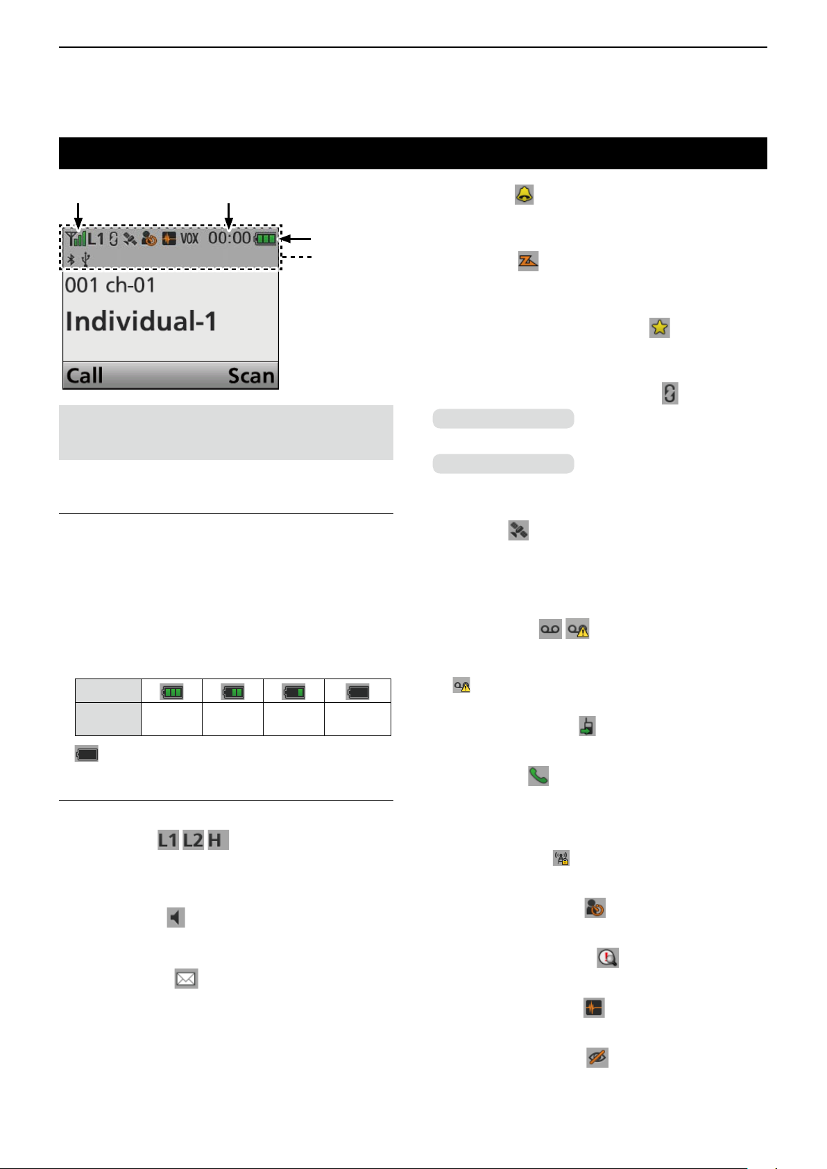
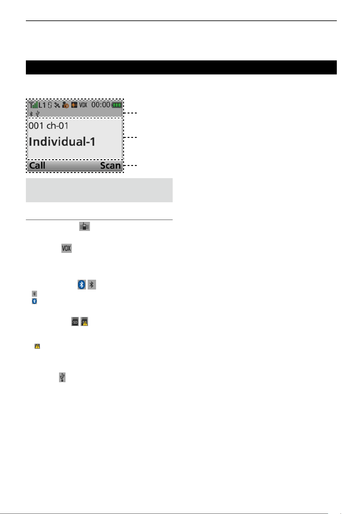
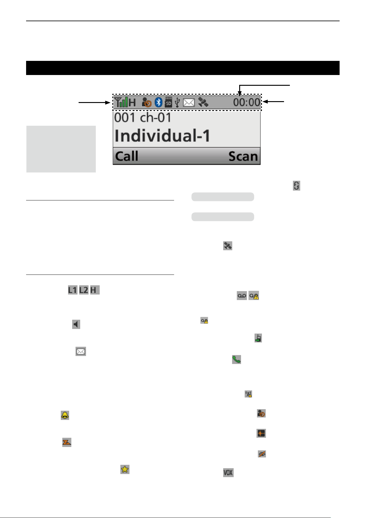
Function display (for the Portable type transceiver)
q w
e
Icon Area
NOTE: The screen capture is an example. The
displayed position of each icon may differ, depending
on the function being used.
D Icon Area
Indicators
q SIGNAL STRENGTH INDICATOR
Displays the relative receive signal strength level.
w CLOCK
Displays the current time.
L “AM” or “PM” is displayed beside the time display when
the 12 hour display format is selected.
L “--:--” is displayed instead of the current time when the
internal clock is not set.
e BATTERY INDICATOR
Displayed or blinks to indicate the battery status.
Indication
Battery
status
Full Mid
blinks when the battery is exhausted.
Charging
required
Battery
exhausted
BELL ICON
Displayed when a matching signal is received,
depending on the presetting.
SCAN ICON
• Displayed when a scan is paused.
• Blinks while scanning.
SCAN TARGET CHANNEL ICON
Displayed when the channel is selected as a scan
target channel.
SCRAMBLER/ENCRYPTION ICON
In the Analog mode
Displayed when the Voice Scrambler function is ON.
In the Digital mode
• Displayed when the Voice Encryption function is ON.
• Blinks when decoding an encrypted signal.
GPS ICON
• Displayed when valid position data is received.
• Blinks when searching for satellites or calculating
position data.
L Depending on the presetting, the GPS icon is not displayed.
RECORD ICON
• Displayed when the Record function is ON.
• Blinks while recording audio.
L “ ” is displayed when there is no microSD card free
space and audio cannot be recorded.
TALK AROUND ICON
Displayed when the Talk Around function is ON.
Icons
The following icons are displayed in the Icon Area.
POWER ICON
• “L1” is displayed when the output power is set to Low.
• “L2” is displayed when the output power is set to Mid.
• “H” is displayed when the output power is set to High.
AUDIBLE ICON
Displayed when the channel is in the ‘audible’
(unmute) mode.
MESSAGE ICON
• Blinks after Messages (Message or Status Message)
have been received.
• Stops blinking when the screen is changed, or any
key is pushed, but is displayed if unread messages
are still in the Message memory.
• Disappears when all messages in the Message
memory have been read.
PHONE ICON
• Displayed when the transceiver is connected to a
telephone network on the selected channel.
• Blinks while receiving a phone call.
SITE LOCK ICON
Displayed when the Site Lock function is ON.
LONE WORKER ICON
Displayed when the Lone Worker function is ON.
MOTION SENSOR ICON
Displayed when the Motion Sensor function is ON.
NOISE CANCEL ICON
Displayed when the Noise Cancel function is ON.
SURVEILLANCE ICON
Displayed when the Surveillance function is ON.
☞ Continued on the next page
2-3
Page 12
2
PANEL DESCRIPTION
Function display (for the Portable type transceiver)
Icon Area
T ext Area
Key Display
Area
NOTE: The screen capture is an example. The
displayed position of each icon may differ, depending
on the function being used.
Icons (Continued)
VIBRATION ICON
Displayed when the Vibration function is ON.
VOX ICON*
Displayed when the VOX function is ON.
* VS-5MC, VS-3, or other Bluetooth headset is
required to use the VOX function.
Bluetooth® ICON
• " " is displayed when Bluetooth® is activated.
• " " is displayed when a Bluetooth® device is
connected.
microSD ICON
Displayed when the microSD card is inserted into the
card slot.
L “ ”
is displayed when the microSD card has not been
formatted.
L Depending on the presetting, the microSD icon is not
displayed.
USB ICON
Displayed when a USB device is connected.
D Text Area
Displays the selected Zone number, channel number,
and, if entered, channel name.
D Key Display Area
Displays the names of the function assigned to [P1]
and [P2].
2-4
Page 13
2
PANEL DESCRIPTION
Front, top and side panels (for the Mobile type transceiver)
Status
indicator
[VOL]
Microphone
connector
Function
display
[P1] [P2]
D About the Status indicator
• Lights red while transmitting.
• Lights green while receiving a signal, or when the
squelch is open.
D About the Microphone connector
Connect the supplied or optional microphone.
CAUTION: DO NOT
microphones. The pin assignments may be different
and may damage the transceiver.
connectnon-specied
[Emer]
[OK]
[Up]/[Down]
[Right]/[Left]
Speaker
[Back]
Power key
D About the Software key functions
NOTE: Dealers can assign the Software key
functions to the keys and keypads, except for the
Power key.
LSee page 2-12 for details.
2-5
Page 14
2
PANEL DESCRIPTION
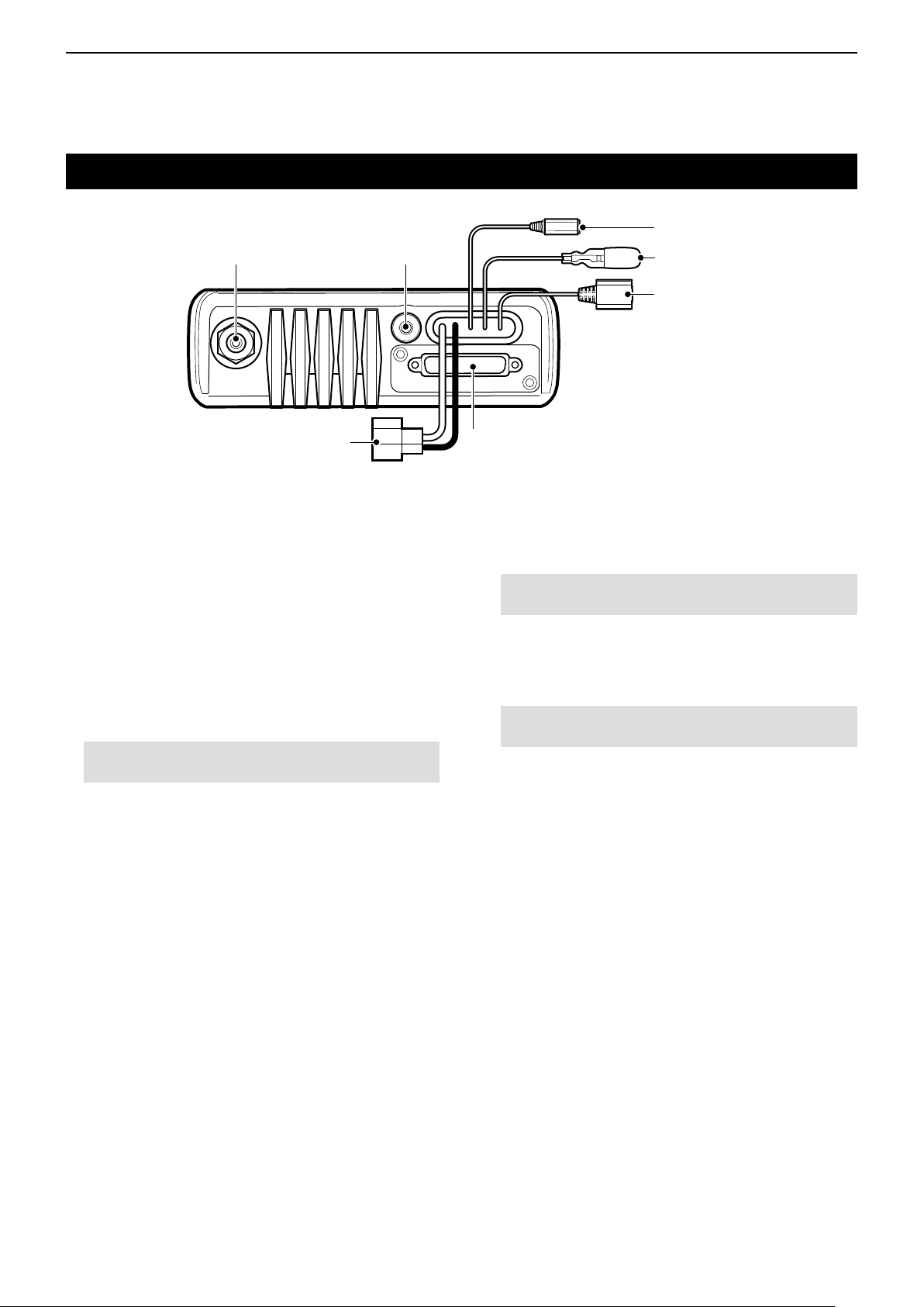
Rear panel (for the Mobile type transceiver)
ANTENNA
q w
CONNECTOR
DC POWER CABLE
u
GPS ANTENNA
CONNECTOR
D-SUB 25 PIN CONNECTOR
y
EXTERNAL SPEAKER JACK
e
IGNITION LEAD
r
USB CABLE
t
q ANTENNA CONNECTOR
Connect to an antenna.
w GPS ANTENNA CONNECTOR
Connect the UX-241 GPS antenna.
e EXTERNAL SPEAKER JACK
Connecta4~8Ωexternalspeaker.
r IGNITION LEAD
Connects to a vehicle ignition line.
CAUTION: DO NOT put pressure on this lead.
Binding to the DC power cable is recommended.
t USB CABLE
Connects to a PC.
y D-SUB 25 PIN CONNECTOR
Connects to an external unit.
NOTE: When connecting an external unit to this
connector,besuretormlytightenthescrews.
u DC POWER CABLE
Connects to a 12 V DC battery.
Pay attention to polarities.
CAUTION: DO NOT connect to a 24 V battery.
This will damage the transceiver.
2-6
Page 15
2
PANEL DESCRIPTION
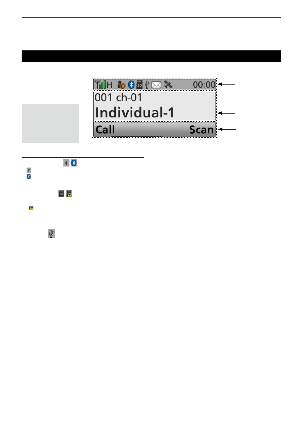
Function display (for the Mobile type transceiver)
w
q
NOTE: The screen
capture is an example.
The displayed position
of each icon may differ,
depending on the
function being used.
D Icon Area
Indicators
q SIGNAL STRENGTH INDICATOR
Displays the relative received signal strength.
w CLOCK
Displays the current time.
L “AM” or “PM” is displayed beside the time display when
the 12 hour display format is selected.
L “--:--” is displayed instead of the current time when the
internal clock is not set.
Icons
The following icons are displayed in the Icon Area.
POWER ICON
• “L1” is displayed when the output power is set to Low.
• “L2” is displayed when the output power is set to Mid.
• “H” is displayed when the output power is set to High.
AUDIBLE ICON
Displayed when the channel is in the ‘audible’
(unmute) mode.
MESSAGE ICON
• Blinks after Messages (Short Message or Status
Message) have been received.
• Stops blinking when the screen is changed, or any
key is pushed, but is displayed if unread messages
are still in the Message memory.
• Disappears when all messages in the Message
memory have been read.
Icon Area
SCRAMBLER/ENCRYPTION ICON
In the Analog mode
Displayed when the Voice Scrambler function is ON.
In the Digital mode
• Displayed when the Voice Encryption function is ON.
• Blinks when decoding an encrypted signal.
GPS ICON
• Displayed when a valid position data is received.
• Blinks when searching for satellites or calculating
position data.
L Depending on the presetting, the GPS icon is not
displayed.
RECORD ICON
• Displayed when the Record function is ON.
• Blinks while recording the audio.
L “ ” is displayed when there is no microSD card free
space and audio cannot be recorded.
T ALK AROUND ICON
Displayed when the Talk Around function is ON.
PHONE ICON
• Displayed when the transceiver is connected to a
telephone network on the selected channel.
• Blinks while receiving a phone call.
SITE LOCK ICON
Displayed when the Site Lock function is ON.
BELL ICON
Displayed when a matching signal is received,
depending on the presetting.
SCAN ICON
• Displayed when a scan is paused.
• Blinks while scanning.
SCAN TARGET CHANNEL ICON
Displayed when the channel is selected as a scan
target channel.
LONE WORKER ICON
Displayed when the Lone Worker function is ON.
NOISE CANCEL ICON
Displayed when the Noise Cancel function is ON.
SURVEILLANCE ICON
Displayed when the Surveillance function is ON.
VOX ICON
Displayed when the VOX function is ON.
2-7
Page 16
2
PANEL DESCRIPTION
Function display (for the Mobile type transceiver)
Icon Area
NOTE: The screen
capture is an example.
The displayed position
of each icon may differ,
depending on the
function being used.
Icons (Continued)
Bluetooth® ICON
• " " is displayed when Bluetooth® is activated.
• " " is displayed when a Bluetooth® device is
connected.
microSD ICON
Displayed when a microSD card is inserted.
L “ ”
is displayed when the microSD card has not been
formatted.
L Depending on the presetting, the microSD icon is not
displayed.
USB ICON
Displayed when a USB device is connected.
T ext Area
Key Display Area
D Text Area
Displays the selected Zone number, Channel number,
and Channel name, if set.
D Key Display Area
Displays the names of the function assigned to [P1]
and [P2].
2-8
Page 17
2
PANEL DESCRIPTION
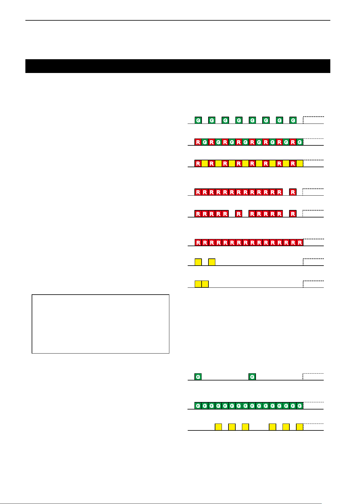
Status indicator
The Status indicator indicates the status of various
parameters of the transceiver, as described below.
(Reference: R=Red, G=Green, Y=Yellow,
M=Magenta, W=White, B=Blue)
• Programming:
Blinks while reading or writing data.
• Programming Error:
Blinks if programming fails.
• Channel Error:
Blinks when you select a blank channel, or an
unlocked channel.
• TX low Battery 1:
Blinks while detecting a low battery in the TX mode.
• TX low Battery 2:
Blinks while detecting a very low battery in the TX
mode.
G G G G G G G GG G G G G G G G
R G R G R G R G R G R G R G R GR G R G R G R G R G R G R G R G
R R R R R R R RR R R R R R R RY Y Y Y Y Y Y Y
R R R R R RR R R R R R R RR R R R R RR R R R R R R R
R R R R R R R R R R R RR R R R R R R R R R R R
• TX:
Lights while transmitting.
• Bell (Blink):
Blinks about twice every second.*
• Bell (ON):
Blinks about once every second.*
*Depending on the “Bell” setting, the Status
indicator blinks:
• When a call that includes a matching 2-Tone
code is received.
• When a Call Alert is received.
• When a Short Message is received.
• When a Status call that includes a matching
status number is received.
• Scan/Hunt:
Blinks while scanning for a channel with a signal, or
while hunting for a control channel..
• RX:
Lights while receiving a signal.
R R R R R R R RR R R R R R R RR R R R R R R RR R R R R R R R
Y Y
Y Y
G GG G
G G G G G G G GG G G G G G G GG G G G G G G GG G G G G G G G
• CH Access:
Blinks while making a call.
Y Y Y Y Y Y
2-9
Page 18
2
PANEL DESCRIPTION
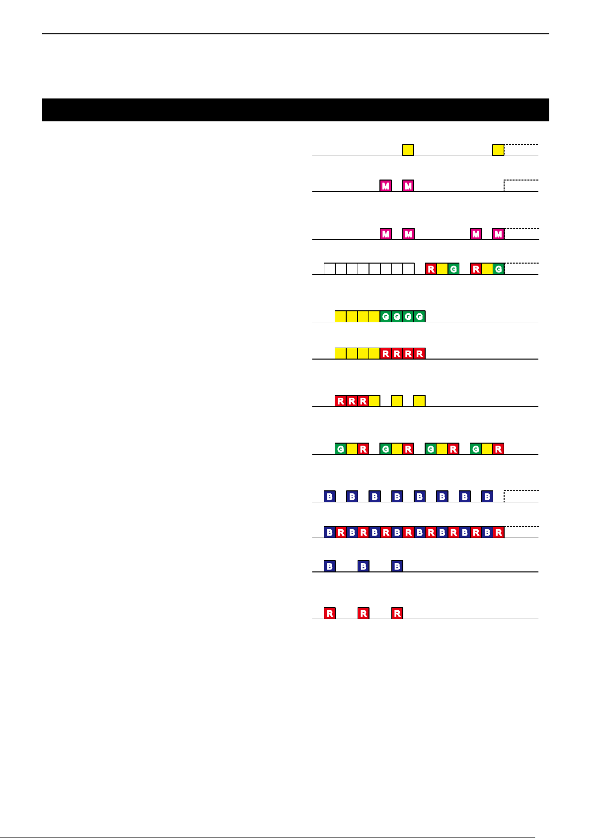
Status indicator (Continued)
• Audible:
Blinks while in the Audible mode.
• Low Battery 1:
Blinks slowly when you should charge the battery
soon.
• Low Battery 2:
Blinks fast when you must charge the battery.
• Power ON:
Lights white, then blinks red, yellow, and green at
transceiver startup.
• Success:
Blinks slowly when your call was successful.
• Failure:
Blinks slowly when your call failed, or it was
refused.
Y Y
MM MM
M M MM M M MM
W W W W WW W W Y YR G R GR G R G
YY YY G GGG G GGG
Y Y YY RRR RRRR R
• TX Error:
Blinks when transmission is inhibited (Lockout, TX
Inh, or TOT Penalty timer).
• Emergency:
Blinks while the Emergency Locator tone is
sounding.
• Searching (Bluetooth®):
Blinks while searching for the Bluetooth® device.
• Waiting Paring (Bluetooth®):
Blinks while in the Waiting Pairing mode.
• Success (Bluetooth®):
Blinks when the Bluetooth® connection is
successful.
• Failure (Bluetooth®):
Blinks when the Bluetooth® connection has failed.
R R RR R R Y Y Y
Y Y Y YRG RG RG RGRG RG RG RG
B B B B B B B BB B B B B B B BB B B B B B B B
B R R R R R R RB B B B B B B RB R R R R R R RB B B B B B B R
B B BB B B
R R RR R R
2-10
Page 19
2
PANEL DESCRIPTION
Assignable keys, keypads, and AB Switch
D Portable type
Dealers can assign the Software key functions to the
following keys, keypads, and the AB Switch.
Simple key type
[P1], [P2], [Up], [Down], [Left], [Right], [OK], [Back],
[F1], [F2], [F3], [Emer], and the AB Switch
Ten-key type
[P1], [P2], [Up], [Down], [Left], [Right], [OK], [Back],
[F1], [F2], [F3], [Emer], Keypad 0~9, M, #, and the AB
Switch
[Emer]
AB
Switch
[F1]
D Mobile type
Dealers can assign the Software key functions to the
following keys and keypads.
[P1], [P2], [Up], [Down], [Left], [Right], [OK], [Back],
and [Emer]
[Emer]
[OK]
[OK]
[F2]
[F3]
[Up]/[Down]
[Right]/[Left]
The illustration is of the Ten-key types.
[P1]
[P2]
[Back]
Ten-Key
Pad
[P1] [P2]
[Up]/[Down]
[Right]/[Left]
[Back]
2-11
Page 20

2
PANEL DESCRIPTION
Assignable Software key functions
D For keys and keypads
Category Assignable function
Disable (p. 2-14)
–
Channel/
Scan (Voting)
Signaling/
Call
Null (p. 2-14)
Menu (p. 2-14)
Home (p. 2-14)
CH Up, CH Down (p. 2-14)
Prio A, Prio B (p. 2-14)
Prio A (Rewrite),
Prio B (Rewrite) (p. 2-14)
Zone Up,
Zone Down (p. 2-14)
Zone Select (p. 2-14)
Scan Start/Stop (p. 2-14)
Scan Add/Del (Tag)
(p. 2-15)
Talkgroup Scan Start/Stop*
(p. 2-15)
High/Low (p. 2-15)
C.Tone CH Select
Tone/NAC CH Select
(p. 2-15)
Monitor (p. 2-15)
Talk Around (p. 2-15)
Bandwidth (p. 2-15)
Scrambler/Encryption*
(p. 2-15)
CKR Select*1 (p. 2-15)
Compander (p. 2-15)
Call (p. 2-16)
Re-dial (p. 2-16)
Call Menu (p. 2-16)
DTMF Autodial (p. 2-16)
Emergency (p. 2-16)
Power OFF Emergency
(p. 2-16)
Individual (p. 2-16)
Group (p. 2-16)
Call Alert (p. 2-16)
Status (p. 2-16)
Message (Short Message)
(p. 2-16)
(p. 2-15)
1
Digital (P25) Analog
Conventional Trunking 2-Tone MDC
✓ ✓ ✓ ✓
✓ ✓ ✓ ✓
✓ ✓ ✓ ✓
✓ ✓ ✓ ✓
✓ ✓ ✓ ✓
✓ ✓ ✓ ✓
✓ ✓ ✓ ✓
✓ ✓ ✓ ✓
✓ ✓ ✓ ✓
✓
✓
1
N/A
N/A
N/A
✓
✓ ✓
✓ ✓
N/A N/A
✓ ✓ ✓ ✓
N/A N/A
✓
✓
N/A
N/A
✓ ✓
✓ ✓
✓ ✓
✓ ✓ ✓ ✓
N/A N/A
✓ ✓
✓ ✓ ✓ ✓
✓ ✓
N/A N/A
N/A N/A
N/A N/A
✓ ✓
✓
✓ ✓ ✓ ✓
✓ ✓
N/A
✓ ✓ ✓ ✓
✓ ✓ ✓ ✓
✓ ✓ ✓ ✓
✓ ✓
✓ ✓
✓ ✓
✓ ✓
✓ ✓
N/A N/A
N/A N/A
N/A
N/A
N/A
N/A
✓
✓
✓
✓
✓: Applicable
N/A: Not Applicable
Depending on the transceiver’s model type, some functions may not be assignable.
*1 For only the revision 2.00 or later.
2-12
☞ Continued on the next page
Page 21

2
PANEL DESCRIPTION
Assignable Software key functions
D For keys and keypads (Continued)
Category Assignable function
Site Alias*1 (p. 2-17)
1
(p. 2-17)
1
(p. 2-17)
1
(p. 2-17)
1
(p. 2-19)
1
(p. 2-19)
(p. 2-19)
(p. 2-19)
1,2
(p. 2-20)
(p. 2-19)
Trunking*
1
Functions
GPS
Voice
Recording
Audio Setting
Bluetooth
Vibration*
3
Display
Control Head
Setting*
1,2
Site Lock*
Site Select*
Site Change Beep*1 (p. 2-17)
Band Scan*
Light (p. 2-18)
Lock (p. 2-18)
Public Address*2 (p. 2-18)
RX Speaker*2 (p. 2-18)
Hook Scan*2 (p. 2-18)
Horn*2 (p. 2-18)
VOX (p. 2-18)
Lone Worker (p. 2-18)
Surveillance (p. 2-18)
AquaQuake*3 (p. 2-18)
Ext.CH Sel Mode (p. 2-18)
USB Mode Select (p. 2-18)
Keyset*1 (p. 2-19)
Zeroize*
Rekey*
GPS ON/OFF (p. 2-19)
GPS Position (p. 2-19)
Call Recorder (p. 2-19)
Play Call Record
TX Noise Cancel (p. 2-19)
RX Noise Cancel
Bluetooth
Waiting Pairing
Vibration*3
Backlight (p. 2-19)
Brightness (p. 2-19)
Dimmer (p. 2-19)
LCD Mode (p. 2-20)
Intercom*
(p. 2-19)
(p. 2-19)
Digital (P25) Analog
Conventional Trunking 2-Tone MDC
N/A
N/A
N/A
N/A
N/A
✓
✓
✓
✓
✓
N/A N/A
N/A N/A
N/A N/A
N/A N/A
N/A N/A
✓ ✓ ✓ ✓
✓ ✓ ✓ ✓
✓ ✓ ✓ ✓
✓ ✓ ✓ ✓
✓ ✓ ✓ ✓
✓ ✓ ✓ ✓
✓ ✓ ✓ ✓
✓ ✓ ✓ ✓
✓ ✓ ✓ ✓
✓ ✓ ✓ ✓
✓ ✓ ✓ ✓
✓ ✓ ✓ ✓
✓ ✓
✓ ✓
✓ ✓
N/A N/A
N/A N/A
N/A N/A
✓ ✓ ✓ ✓
✓ ✓ ✓ ✓
✓ ✓ ✓ ✓
✓ ✓ ✓ ✓
✓ ✓ ✓ ✓
✓ ✓ ✓ ✓
✓ ✓ ✓ ✓
✓ ✓ ✓ ✓
✓ ✓ ✓ ✓
✓ ✓ ✓ ✓
✓ ✓ ✓ ✓
✓ ✓ ✓ ✓
✓ ✓ ✓ ✓
✓ ✓ ✓ ✓
✓: Applicable
N/A: Not Applicable
Depending on the transceiver’s model type, some functions may not be assignable.
*1 For only the revision 2.00 or later.
2
*
For only Mobile type transceivers.
3
*
For only Portable type transceivers.
2-13
Page 22

2
PANEL DESCRIPTION
Assignable Software key functions
D For keys and keypads (Continued)
Disable
Set to disable the key.
NOTE: This key function is assignable to only
[Ext. Emer].
Null
No function.
Menu
Push to display the “Menu” screen.
L Depending on the presetting, you may be able to make
various calls, select various functions and adjust the
transceiver settings in the Menu screen.
L In the Menu screen, you cannot use the assigned key
functions.
Home
In the Analog mode
z While in the Audible mode, push to return to the
Inaudible mode.
In the Digital mode
z Push to reset the Group ID, if they have been
manually changed.
z Push to cancel the Talk Back function, if it is
activated.
z While in the Selection mode (Message, Status
Message, and so on), hold down for 1 second to
return to the Standby mode.
• The transceiver resets the Group ID.
z While in the Trunk channel, push to reset the Site
Select setting.
Category: Channel/Scan (Voting)
CH Up, CH Down
z Push to select an operating channel.
z Afterpushingspecickeys,pushtoselectan
option, setting, and so on.
Priority A, Priority B
Push to select the Priority A or Priority B channel.
Priority A (Rewrite), Priority B (Rewrite)
z Push to select the Priority A or Priority B channel.
z Hold down for 1 second to assign the operating
channel to the Priority A or Priority B channel.
Zone Up, Zone Down
Push to select an operating zone.
Zone Select
Push to display the “Zone Select” screen. Then, push
[Up] or [Down] to select a zone.
TIP: What is a “zone”?
Certain channels are grouped together and assigned
to a zone according to their intended use.
For example, ‘Staff A’ and ‘Staff B’ are assigned to a
“Business” zone, and ‘John’ and ‘Cindy’ are assigned
to a “Private” zone.
Scan Start/Stop
z Push to start or cancel a Scan.
L When a scan started with the Power ON Scan or Auto
Scan function, pushing this key pauses the scan. The
paused scan resumes after the preset time period has
passed.
z Hold down for 1 second to display the “Scan List”
screen. Then push [Up] or [Down] to select a list.
2-14
NOTE: When Mode Dependent Scan is ON, a
user may not be able to display the Scan list,
depending on the presetting.
Page 23

2
PANEL DESCRIPTION
Assignable Software key functions
D For keys and keypads (Continued)
Category: Channel/Scan (Voting) (Continued)
Scan Add/Del (Tag)
z Push to add a channel to, or delete it from the
current Scan list.
• When a channel is added to the current Scan list, the
currentScanlisttextand“ON”arebrieydisplayed.
• When a channel is deleted from the current Scan
list,thecurrentScanlisttextand“OFF”arebriey
displayed.
z You can add a channel to, or delete it from a
selected Scan list.
1. Hold down for 1 second to display the “Scan Tag”
screen.
2. Push [Up] or [Down] to select a list.
3. Push [OK] to add a channel to, or delete it from
the selected list.
• When a channel is added to the selected Scan
list,thecurrentScanlisttextand“ON”arebriey
displayed.
• When a channel is deleted from the selected Scan
list,thecurrentScanlisttextand“OFF”arebriey
displayed.
4. Push [Back] to exit the “Scan Tag” screen.
z While a Scan is paused by detecting a signal on a
channel (except for primary or secondary channel),
push this key to remove the channel from the Scan
list.
TIP: When the Nuisance Delete function is ON,
the removed channel is automatically added to the
Scan list again, after the Scan is canceled.
Talkgroup Scan Start/Stop
(For only the revision 2.00 or later.)
Push to start or cancel the Talkgroup scan.
You can monitor the trunking group’s communication.
The function scans up to 8 Talkgroup IDs and Memory
channels. If the transceiver is out of range, this key is
disabled.
High/Low
Push to select the transmit output power level
temporarily or permanently, depending on the
presetting.
C.Tone CH Select
In the Analog mode
Push to display the “C.Tone CH Select” screen. Then
push [Up] or [Down] to select a tone frequency or
code. After selecting, push [OK] to save.
Tone/NAC CH Select
In the Analog mode
Push to display the “C.Tone CH Select” screen. Then
push [Up] or [Down] to select a tone frequency or
code. After selecting, push [OK] to save.
In the Digital mode
Push to display the “NAC CH Select” screen. Then
push [Up] or [Down] to select a NAC code. After
selecting, push [OK] to save.
Monitor
z Push to turn the CTCSS (DTCS) or 2-Tone squelch
mute ON or OFF.
L Only during 2-Tone mode operation, push to open any
squelch, or deactivate any mute functions.
(Depending on the presetting):
- Hold down to unmute the channel (Audible mode).
- Push to mute the channel (Inaudible mode).
NOTE: The audible (unmute) mode may
automatically return to the Inaudible (mute) mode,
after the preset time period.
z Depending on the presetting, holding down this key
for 1 second may cancel the Scan.
T alk Around
Push to turn the Talk Around function ON or OFF.
L The Talk Around function equalizes the transmit
frequency to the receive frequency, for direct (Simplex)
communication.
Bandwidth
In the Analog mode
Push to temporarily set the channel width to Wide* or
Narrow.
L The wide passband width can be preset to either 25.0 kHz
(Wide) or 20.0 kHz (Mid).Depending on the presetting,
Mid channel width may be selectable.
* The Wide channel width cannot be used for the USA
version transceivers.
Scrambler/Encryption
In the Analog mode
Push to turn the Voice Scrambler function ON or OFF.
L The Voice Scrambler function provides private
communication between stations by using a scrambled
code.
In the Digital mode (For only the revision 2.00 or later.)
Push to turn the Voice Encryption function ON or OFF.
L The Voice or Data Encryption function provides private
communication between stations by using an Encryption
Key and Key ID.
CKR Select (For only the revision 2.00 or later.)
Select the Encryption's Common Key Reference (CKR).
2-15
Page 24

2
PANEL DESCRIPTION
Assignable Software key functions
D For keys and keypads (Continued)
Category: Channel/Scan (Voting) (Continued)
Compander
In the Analog mode
Push to turn the Compander function ON or OFF.
L The Compander function reduces noise components on
the transmit audio to provide clear communication.
Category: Signaling/Call
Call
In the Analog mode
Push to make a call to the preset destination in the
channel.
Re-dial
Push to send the last transmitted DTMF code number.
L Redial will be cleared when the transceiver is turned OFF
once.
Call Menu
1. Push to display the “Call Menu” screen.
2. Push [Up] or [Down] to select a call function.
L See ‘Transmitting a call’ on sections 7 and 8 for
details.
3. After selecting, push [OK] to set, and display the
call function screen.
4. Push [Up] or [Down] to select an ID name (or ID
code).
5. After selecting, push [PTT] to make a call to the
selected station or group.
DTMF Autodial
z Push to display the “DTMF Autodial” screen. Then,
push [Up] or [Down] to select a DTMF code. After
selecting, push [PTT] to transmit the selected DTMF
code.
z While in the Standby mode, hold down for 1 second
to transmit the currently selected DTMF code.
Power OFF Emergency
(For the Mobile type transceivers)
While holding down this key, turn OFF the transceiver
to activate the Power OFF Emergency function.
NOTE: This key function is assignable to only [Emer]
or [Ext. Emer].
LInformation
• This function makes the transceiver transmit
Emergency calls, even though it appears to be
powered OFF.
• When the function is activated, any key operation,
hanger action and Lone Worker function becomes
invalid, as well as the Status indicator and speaker
become the same as being powered OFF.
On the other hand, the transceiver can transmit
Emergency calls according to the Emergency
settings, and the Ambience Listening function is also
activated, if it is set.
• To cancel the function and restore the transceiver,
turn ON the transceiver.
Individual
In the Digital mode
Push to display the “Individual ID” screen. Then, push
[Up] or [Down] to select an Individual ID name (or ID
code).
After selecting, push [OK] to set.
Group
In the Digital mode
Push to display the “Group ID” screen. Then, push
[Up] or [Down] to select an Group ID name (or ID
code).
After selecting, push [OK] to set.
Call Alert
Hold down for 1 second to transmit a Call Alert.
Emergency
1. Hold down during the Emer SW ON Timer period
to enter the Emergency mode.
2. After the Reminder Timer period has passed, an
Emergency call is automatically transmitted once,
or repeatedly.
NOTE:
• Set the related settings using the programming
software.
• This key function is assignable to only [Emer] or
[Ext. Emer].
L Hold down during the Emer SW OFF Timer period to
cancel the Emergency function, before transmitting an
Emergency call.
Status
Push to display the “Status List” screen. Then, push
[Up] or [Down] to select a Status message.
L See pages 7-6, 8-14 for details.
Message (Short Message)
While in the Standby mode, push to display the
“Message List” screen. Then, push [Up] or [Down] to
select a message.
L See pages 7-3, 8-4 for details.
2-16
Page 25

2
PANEL DESCRIPTION
Assignable Software key functions
D For keys and keypads (Continued)
Category: Trunking
(For only the revision 2.00 or later.)
Site Alias
Push to display the RFSS ID and Site ID, or the Site
Alias name if entered.
Site Lock
Locks the transceiver in the current registered site.
This function inhibits the transceiver from roaming
other sites.
Site Select
Edit the RFSS ID or connect to the site.
Editing the RFSS ID:
1. Push to display the current site name.
2. While displaying the site, push [OK] to display its
RFSS ID and the Site ID.
3. Hold down [OK] to enter the editing mode.
4. Push [Up] or [Down] to set.
Connecting to the site:
1. Push to display the current site name.
2. Hold down [OK] to connect to the site.
3. While displaying the site, hold down [OK] to
connect to the site.
Site Change Beep
Select whether or not to sound a beep after
registrationandgroupafliationaresuccessfulinthe
Trunking system.
Band Scan
Push to start and cancel the Band Scan.
L You cannot use this key while scanning, transmitting, or in
the Conventional mode.
2-17
Page 26

2
PANEL DESCRIPTION
Assignable Software key functions
D For keys and keypads
Category: Functions
Light
Push to turn ON the backlight for about 5 seconds,
even if the backlight setting is OFF.
Lock
Hold down for 1 second to turn the Key Lock function
ON or OFF.
L All assignable keys except the following are electronically
locked: [Monitor], [Light], [Lock], [Call], [Emergency],
[Surveillance] and [Lone worker]. Also, [PTT] and [Power]
are usable.
Public Address (For the Mobile type transceivers)
Push to activate the Public Address (PA) function.
And then, speak into the microphone while holding
down [PTT].
L When the PA function is activated, the audio output can
be separately controlled from the transceiver by pushing
[Up] or [Down].
NOTE: This function is usable when an external
unit,suchasaaudioamplier,speaker,andsoonis
connected to the D-Sub 25 pin connector.
RX Speaker (For the Mobile type transceivers)
Push to turn the RX Speaker function ON or OFF.
L When the RX Speaker function is turned ON, the received
audio can be heard through an external speaker that is
connected to the D-Sub 25 pin connector.
NOTE:
• This function is usable when an external speaker is
connected to the D-Sub 25 pin connector.
• This function is useful when a user is out of the
vehicle.
• The audio output level is linked to the transceiver’s
volume control.
Hook Scan (For the Mobile type transceivers)
Push to temporarily turn the Hook Scan function ON
or OFF.
Horn (For the Mobile type transceivers)
Push to turn the Horn function ON or OFF.
L When the Horn function is ON, the HORN terminal of the
D-Sub 25 pin or Option Connector 22 pin is activated after
receiving a call*.
* Only a call that the Dec EXO or RX EXO setting is ON.
L This function is useful when a user is away from the
transceiver.
NOTE: This function is usable when an external
speaker is connected to the D-Sub 25 pin connector.
VOX
Push to turn the VOX function ON or OFF.
L The function automatically switches between receive and
transmit by detecting your voice.
NOTE: To use the function, a headset* and a VOX
converter cable are required (user supplied).
*Bluetooth headset is also usable.
Lone Worker
Push to turn the Lone Worker function ON or OFF.
LIfnooperationoccursduringthespeciedperiod,the
Lone Worker function automatically makes the transceiver
enter the Emergency mode.
NOTE: To use the Lone Worker function, set the
related settings using the programming software.
Surveillance
Push to turn the Surveillance function ON or OFF.
L When this function is turned ON, the beep is not heard
and the backlight and the Status indicator do not light,
even when a signal is received, or a key is pushed.
AquaQuake (For the Portable type transceivers)
While holding down this key, the AquaQuake water
draining function removes water from the speaker grill
by vibrating the internal speaker.
• Waterinthespeakergrillmaymufethesoundcoming
from the speaker.
NOTE:
• Afterthespeciedperiodoftime,thisfunction
automatically stops, even if a user continues to hold
down this key.
• This key works with only the internal speaker.
Ext.CH Sel Mode
Push to turn the Ext. CH Select function ON or OFF.
L When this function is ON, Memory channels are selected
by only external entry.
NOTE:
• This function is activated when an external unit is
connected to the transceiver.
• To use the function, set the input port function to
“MCH Select:1” to “MCH Select: 5” to any pins,
using the programming software.
USB Mode Select
Push to set the USB port mode to “Card Reader” or
“Data Transfer.”
2-18
Page 27

2
PANEL DESCRIPTION
Assignable Software key functions
D For keys and keypads (Continued)
Keyset (For only the revision 2.00 or later.)
In the Digital mode
Push to enter the keyset selection mode.
Zeroize (For only the revision 2.00 or later.)
In the Digital mode
Hold down for 1 second to zeroize the encryption key
data that is programmed by the key loader.
Rekey (For only the revision 2.00 or later.)
In the Digital mode
Hold down for 1 second to transmit a Key
Management Message (KMM-Hello command) to a
Key Management Facility (KMF) to request rekeying.
Category: GPS
GPS ON/OFF
Push to turn the GPS function ON or OFF.
L When this function is ON, the Latitude, Longitude, and
Altitude data is displayed in the “My Position” screen.
NOTE: If the internal GPS receiver does not receive
position data, no position data is displayed.
RX Noise Cancel
Push to select the RX Noise Cancel level between 1
and 3 to suppress the receive audio noise to make the
audio easy to hear.
L When “OFF” is selected, the receive audio noise is not
suppressed.
Category: Bluetooth
Bluetooth
Push to turn the Bluetooth
®
function ON or OFF.
Waiting Pairing
Push to enter the Pairing Request Wait mode.
• The transceiver waits for a pairing request from a
Bluetooth
®
device.
Category: Vibration
Vibration (For the Portable type transceivers)
Push to turn the Vibration function ON or OFF.
L When “ON” is selected, the transceiver vibrates when a
matching call or ID is received.
Category: Display
Backlight
Push to select the Backlight level.
GPS Position
Push to display the “GPS Position” screen in the
Menu mode.
L See page 6-12 for details.
Category: Voice Recording
Call Recorder
Push to start or stop the voice recording.
NOTE: This key is usable only when a microSD card
is inserted into the transceiver’s card slot.
Play Call Record
Push to display the “Play Call Rec” screen.
L The screen displays the folders that contain recorded
audioles.
L See page 10-4 for details.
NOTE: This key is usable only when a microSD card
is inserted into the transceiver’s card slot.
Category: Audio Setting
TX Noise Cancel
Push to select the TX Noise Cancel level between 1
and 3 to suppress the microphone input noise to make
the audio easy to hear.
L When “OFF” is selected, the microphone input noise is
not suppressed.
(For the Portable type transceivers)
• OFF: The backlight is always OFF.
• ON: The backlight is always ON.
• Auto: When any switch except [PTT] is pushed, the
backlight lights for 5 seconds.
(For the Mobile type transceivers)
• OFF: The backlight is continuously OFF.
• ON: Turns the backlight is continuously ON.
• Auto: Turns the backlight continuously ON with the
Brightness setting level.
When the Dimmer terminal of the D-Sub 25
pin or Option Connector 22 pin is activated,
the backlight lights dimly.
Brightness
Push to open the “Brightness” window. Then, push
[Up] or [Down] to select the desired level between 0
(the lowest) and 7 (the highest).
Dimmer
Push to open the “Dimmer” window. Then, push [Up]
or [Down] to select the desired level between 0 (the
lowest) and 7 (the highest).
NOTE: It is recommended to be the Dimmer level
lower than the Brightness level.
2-19
Page 28
2
PANEL DESCRIPTION
Assignable Software key functions (Continued)
LCD Mode
Push to select the LCD Mode.
• Day : The LCD is set to the Day mode.
The Day mode is for the daytime operation,
and the display backlight color is set to
white.
• Night : The LCD is set to the Night mode.
The Night mode is for the nighttime
operation, and the display backlight color is
set to black.
Category: Control Head Setting
( For only the revision 2.00 or later Moblie type
transceivers)
Intercom
Push to turn the Intercom function ON or OFF.
This function enables the user to communicate
between the optional control heads.
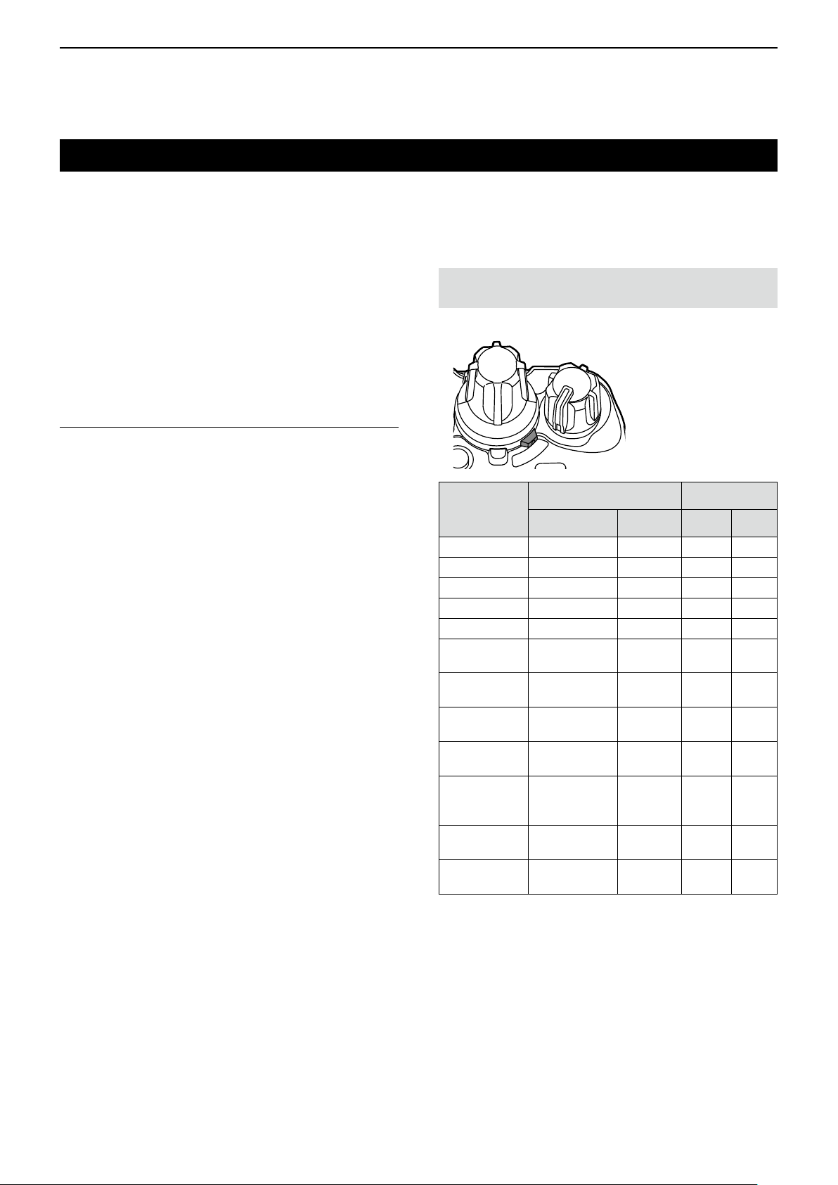
D For the AB Switch
(For the Portable type transceiver)
Functions can be assigned to the AB Switch.
NOTE: The function that is assigned to the AB
Switch, cannot be assigned to any key.
Transceiver’s top view
B
A
Assignable
function
Null (p. 2-21)
Zone (p. 2-21)
Prio-A (p. 2-21)
Prio-B (p. 2-21)
Lock (p. 2-21)
Lone Worker
(p. 2-21)
High/Low
(p. 2-21)
T alk Around
(p. 2-21)
Surveillance
(p. 2-21)
Scrambler/
Encryption
(p. 2-21)
Compander
(p. 2-21)
Site Lock
(p. 2-21)
Digital (P25) Analog
Conventional Trunking 2-Tone MDC
✓ ✓ ✓ ✓
✓ ✓ ✓ ✓
✓ ✓ ✓ ✓
✓ ✓ ✓ ✓
✓ ✓ ✓ ✓
✓ ✓ ✓ ✓
✓ ✓ ✓ ✓
✓ ✓ ✓ ✓
✓ ✓ ✓ ✓
✓ ✓ ✓ ✓
N/A N/A
N/A
✓
✓ ✓
N/A N/A
✓: Applicable
N/A: Not Applicable
2-20
Page 29

2
PANEL DESCRIPTION
Assignable Software key functions
D For the AB Switch (For the Portable type transceiver) (Continued)
Null
No function.
Zone
Rotate to select a zone.
Prio-A/Prio-B
Rotate to select the Priority A or Priority B channel.
Lock
Rotate to turn the key lock function ON.
Lone Worker
Turns the Lone Worker function ON or OFF.
LIfnooperationoccursduringthespeciedperiod,the
Lone Worker function automatically makes the transceiver
enter the emergency mode.
NOTE: To use the Lone Worker function, set the
related settings using the programming software.
High/Low
Rotate to switch the transmit output power to “Low1”
from the independent settings fro each channel.
Site Lock
Locks the transceiver in the current registered site.
This function inhibits the transceiver from roaming
other sites.
T alk Around
Rotate to turn the Talk Around function ON.
L The Talk Around function equalizes the transmit frequency
to the receive frequency for transceiver-to-transceiver
communication.
Surveillance
Rotate to turn the Surveillance function ON.
L When this function is turned ON, the beep is not heard
and the backlight and the Status indicator do not light,
even when a signal is received, or a key is pushed.
Scrambler/Encryption
In the Analog mode
Rotate to turn the Voice Scrambler function ON.
L The Voice Scrambler function provides private
communication between stations.
In the Digital mode (For only the revision 2.00 or later.)
Push to turn the Voice Encryption function ON or OFF
L The Voice or Data Encryption function provides private
communication between stations by using an Encryption
Key and Key ID.
Compander
In the Analog mode
Rotate to turn the Compander function ON.
2-21
Page 30

Section 3
BASIC OPERATION
Turning ON the transceiver ....................................................3-2
D Adjusting the audio level ................................................. 3-2
D Entering the password ....................................................3-2
Selecting a Zone..................................................................... 3-3
D Selecting a Zone ............................................................. 3-3
Selecting a channel ................................................................ 3-4
D Selecting an operating channel. ..................................... 3-4
D Selecting the Priority A or B channel ............................... 3-4
D Rewriting the Priority A or B channel ............................. 3-5
D Selecting a Continuous tone channel ............................. 3-5
D Selecting a NAC channel ................................................ 3-6
Call procedure ........................................................................ 3-7
Receiving and transmitting ..................................................... 3-8
D Transmitting notes .......................................................... 3-8
Key Lock function ................................................................... 3-9
3-1
Page 31

3
BASIC OPERATION
Turning ON the transceiver
NOTE: Before using the transceiver for the rst time,
the battery pack must be fully charged for optimum
life and operation. See the INSTRUCTIONS for
details.
Portable:
Rotate [VOL] to turn ON the transceiver.
• The battery voltage or the opening text may be displayed,
depending on the presetting.
Mobile:
Push the Power key to turn ON the transceiver.
• The opening text may be displayed, depending on the
presetting.
D Adjusting the audio level
When receiving a call, rotate [VOL] to adjust the audio
output level to a comfortable listening level.
D Entering the password
[VOL]
[OK]
[VOL]
[Up], [Down],
[Right], [Left]
[OK]
Power key
[Up], [Down],
[Right], [Left]
1. If the transceiver is preset for a Power ON
password when turning ON the transceiver, the
“User Password” screen is displayed, as shown to
the right.
2. Push [Up], [Down], [Right], or [Left] to select a
number, then push [OK] to enter.
3. Repeat step 2 to enter the password.
4. After entering the correct password, the
transceiver automatically displays the standby
screen.
NOTE: If the transceiver does not display the
standby screen after entering the password, the
entered code may be incorrect. In this case, push
[Back] several times until you delete the incorrect
code, and then enter the correct code.
TIP: For the Portable Ten-key type transceiver or
optional HM-220T/HM-221T, a user can enter the
password with the keypad.
Standby screen
3-2
Page 32

3
BASIC OPERATION
Selecting a Zone
D Selecting a Zone
Select a Zone type from Conventional or Voting.
<Menu operation>
TIP: What is a “Zone”?
Certain channels are grouped together and assigned
to a Zone according to their intended use.
For example, ‘Staff A’ and ‘Staff B’ are assigned
to a “Business” Zone, and ‘John’ and ‘Cindy’ are
assigned to a “Private” Zone.
<Key or Selector operation>
Portable: For all types
Mobile: For all types
z Rotate [Selector]*. (Only the Portable type)
*When “Zone” is assigned.
z Push [Zone Up] or [Zone Down].
z Push [Zone Select] to display the “Zone Select”
screen. Then, push [Up] or [Down] to select a Zone.
After selecting, push [OK].
(Menu > Channel/Scan > Zone Select)
1. Push [Menu] to display the Menu screen.
2. Push [Left] or [Right] to select “Channel/Scan,”
push [OK].
then
3. Push [Up] or [Down] to select “Zone Select,” then
push [OK].
• Displays the “Zone Select” screen.
4. Push [Up] or [Down] to select a Zone, then push
[OK].
5. The selected Zone is displayed.
3-3
Page 33

3
hand
microphone
abc
BASIC OPERATION
Selecting a channel
D Selecting an operating channel
<Key or Selector operation>
z Rotate [Selector]. (Only the Portable type)
z Push [CH Up] or [CH Down].
<Ten-key operation>
Portable: For the Ten-key type
Mobile: For the optional HM-220T or HM-221T
z Push the keypad to directly enter a channel number,
depending on the presetting.
Example: Selecting Channel 2
Push [0] → [0] → [2
<Voting operation>
The transceiver automatically starts scanning when a
Zone speci ed for the Voting operation is selected.
The Voting scan detects the signal strength of the
repeaters, and automatically selects the strongest
one.
<Automatic Scan operation>
Depending on the presetting, when the user turns ON
the transceiver, a scan automatically starts. The scan
stops when a call is received.
].
D Selecting the Priority A or B channel
<Key operation>
Push [Prio-A] or [Prio-B] to select the Priority A or
Priority B channel.
<Menu operation>
(Menu > Channel/Scan > Priority A CH)
(Menu > Channel/Scan > Priority B CH)
1. Push [Menu] to display the “Menu” screen.
2. Push [Left] or [Right] to select “Channel/Scan,”
then
push [OK].
3. Push [Up] or [Down] to select “Priority A CH” or
“Priority B CH,” then
push [OK].
(Example: Priority A CH)
4. Hold down [Back] for 1 second to return to the
standby screen.
3-4
Page 34

3
BASIC OPERATION
Selecting a channel (Continued)
D Rewriting the Priority A or B channel
<Key operation>
1. Select a channel to be set as the Priority A or B
channel. (p. 3-4)
2. Hold down [Prio A (Rewrite)] or [Prio B (Rewrite)]
for 1 second.
• Sets the selected channel as the Priority A or B
channel.
<Menu operation>
(Menu > Channel/Scan > Prio A (Rewrite))
(Menu > Channel/Scan > Prio B (Rewrite))
1. Select a desired channel to be set as the Priority
A or B channel. (p. 3-4)
2. Push [Menu] to display the “Menu” screen.
3. Push [Left] or [Right] to select “Channel/Scan,”
then
push [OK].
4. Push [Up] or [Down] to select “Prio A (Rewrite)” or
“Prio B (Rewrite).”
D Selecting a Continuous tone channel
<Key operation>
1. While in the Analog mode, push [C.Tone CH
Select] to display the “C.Tone CH Select” screen.
2. Push [Up] or [Down] to select a Continuous tone
channel, then push [OK].
• Sets the selected channel.
<Menu operation>
(Menu > Channel/Scan > C.Tone CH Select)
1. While in the Analog mode, push [Menu] to display
the “Menu” screen.
2. Push [Left] or [Right] to select “Channel/Scan,”
then
push [OK].
3. Push [Up] or [Down] to select “C.Tone CH Select,”
then
push [OK].
• Displays the “C.Tone CH Select” screen.
5. Push
[OK].
• Sets the selected channel as the Priority A or B
channel.
4. Push [Up] or [Down] to select a Continuous tone
channel, then push [OK].
• Sets the selected channel.
5. Hold down [Back] for 1 second to return to the
standby screen.
• The selected Continuous tone channel number is
displayed.
3-5
Page 35

3
BASIC OPERATION
Selecting a channel (Continued)
D Selecting an NAC channel
<Key operation>
1. While in the Digital mode, push [Tone/NAC CH
Select] to display the “NAC CH Select” screen.
2. Push [Up] or [Down] to select an NAC channel,
then push [OK].
• Sets the selected channel.
<Menu operation>
(Menu > Channel/Scan > NAC CH Select)
1. While in the Digital mode, push [Menu] to display
the “Menu” screen.
2. Push [Left] or [Right] to select “Channel/Scan,”
then
push [OK].
3. Push [Up] or [Down] to select “NAC CH Select,”
then
push [OK].
• Displays the “NAC CH Select” screen.
4. Push [Up] or [Down] to select an NAC channel,
then push [OK].
• Sets the selected channel.
5. Hold down [Back] for 1 second to return to the
standby screen.
• The selected NAC channel number is displayed.
3-6
Page 36

3
BASIC OPERATION
Call procedure
When your system uses tone signaling (except
CTCSS and DTCS), a call procedure may be
necessary prior to voice transmission. The tone
signaling employed may be a selective calling system,
which enables you to call only specic stations, and
prevents unwanted stations from contacting you.
1. Select a channel according to your system
operator’s instructions.
• This may not be necessary, depending on the
presetting.
• Refer to page 3-4 for details.
2. Push [Call].
3. After transmitting, the remainder of your
communication can be carried out in the normal
way.
Selective calling
The illustration is of the Ten-key type transceivers.
Non-selective calling
3-7
Page 37

3
BASIC OPERATION
Receiving and transmitting
CAUTION: DO NOT transmit without an antenna. It
may damage the transceiver. See pages 1-3 and 2-6
for accessory attachments.
Receiving:
1. Turn ON the transceiver. (p. 3-2)
2. Select a channel. (p. 3-4)
3. When receiving a call, rotate [VOL] to adjust the
audio output level to a comfortable listening level.
NOTE: Depending on the presetting, the transceiver
may automatically transmit the microphone audio
for the preset time period when a matching signal is
received. (Auto TX function)
Transmitting:
Wait for the channel to become clear to avoid
interference.
1. While holding down [PTT], speak at your normal
voice level.
• To transmit a tone frequency (2-Tone) push [Call].
2. Release [PTT] to return to receive.
D Transmitting notes
Transmit inhibit function
The transceiver has several inhibit functions which
restrict transmission under the following conditions:
• The channel is in the Inaudible mode (“ ”: Audible
icon does not appear.)
• The channel is busy. However, depending on the
presetting, you can transmit when a call is received
that includes a non-matching (or matching) CTCSS
(DTCS), NAC (Network Access Code), Individual ID,
or Group ID.
• The selected channel is a ‘receive only’ channel.
Time-Out timer
If continuous transmission exceeds the preset Time-
Out Timer time, the transmission is cut off.
Penalty timer
After the transmission is cut off by the Time-Out Timer,
transmission is further inhibited for a preset penalty
period of timer.
IMPORTANT: To maximize the readability of your
signal.
1. Pause briefl y after pushing [PTT].
2. Hold the microphone 5 to 10 cm (2 to 4 inches)
from your mouth, then speak at your normal voice
level.
3-8
Page 38

3
BASIC OPERATION
Key Lock function
You can use the Key Lock function to prevent
accidental channel changes and unnecessary function
access.
L All assignable keys except the following are electronically
locked: [Monitor], [Light], [Lock], [Call], [Emergency],
[Surveillance] and [Lone Worker]. Also, [PTT] and [Power]
are usable.
<Key operation>
Hold down for 1 second to turn the Key Lock function
ON or OFF.
NOTE: The Key Lock function can be assigned to
any key, only when it is NOT assigned to the AB
switch.
<AB switch operation>
L The AB switch can be used only when the Key Lock
function is assigned.
z Slide the AB switch to the “A” or “B” position that the
Key Lock function is assigned
function.
z Slide the AB switch to the “A” or “B” position that the
Key Lock function is not assigned
Lock function.
to turn ON the Key Lock
to turn OFF the Key
3-9
Page 39

Section 4
ADVANCED OPERATION
DTMF calls ............................................................................. 4-2
D Manual Dialing ................................................................ 4-2
D Autodial ........................................................................... 4-2
Emergency call ....................................................................... 4-3
D Transmitting an Emergency call ...................................... 4-3
Scrambler ............................................................................... 4-7
Network Access Code (NAC) ................................................4-7
AquaQuake™ Water Draining function
(for the Portable type transceiver) .......................................... 4-8
4-1
Page 40
4
ADVANCED OPERATION
DTMF calls
D Manual Dialing
A user can send DTMF codes.
While holding down [PTT], push the keys on the Ten-
key pad.
D Autodial
A user can quickly send DTMF tones that have been
pre-entered into the transceiver.
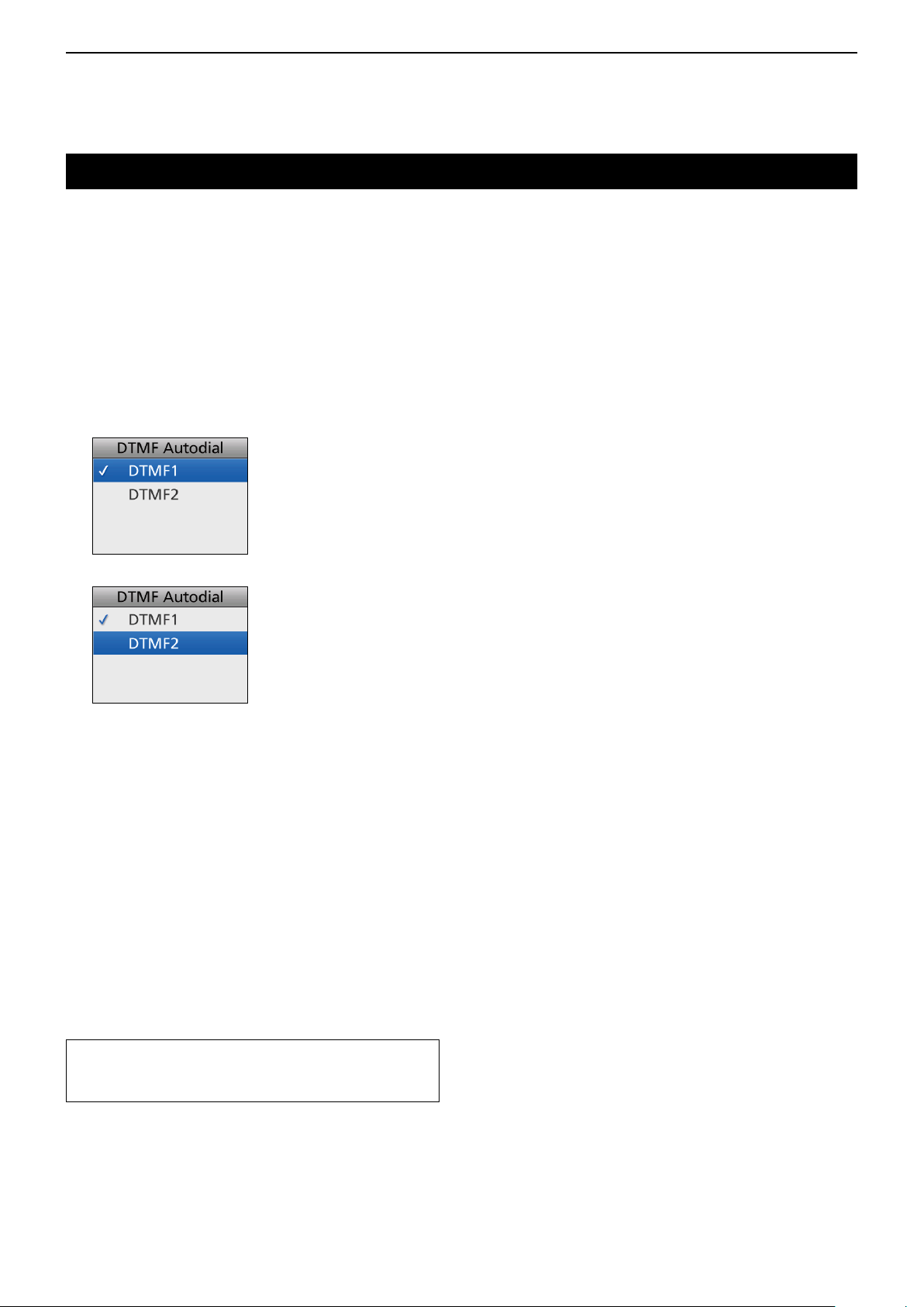
1. Push [DTMF Autodial] to display the “DTMF
Autodial” screen.
2. Push [Up] or [Down] to select a DTMF Memory.
3. Push [PTT] to send the selected DTMF Memory’s
codes.
• After sending, automatically returns to the standby
screen.
TIP: In the standby screen, a user can send the
currently selected DTMF Memory’s codes by
holding down [Autodial].
4-2
Page 41

4
ADVANCED OPERATION
Emergency call
IMPORTANT: It is recommended that the dealer sets
an Emergency channel in each zone, to provide a
reliable Emergency call operation.
NOTE: Depending on the presetting, the following
functions may be automatically activated.
Auto TX function
After an Emergency call transmission, the
transceiver transmits the microphone audio for a
preset period of time.
Auto RX function
After an Emergency call transmission, the
transceiver stands by in the Audible mode for a
preset period of time.
TIP: A user can transmit the Emergency call in the
2-Tone, APCO P25, or MDC 1200 signaling system.
D Transmitting an Emergency call
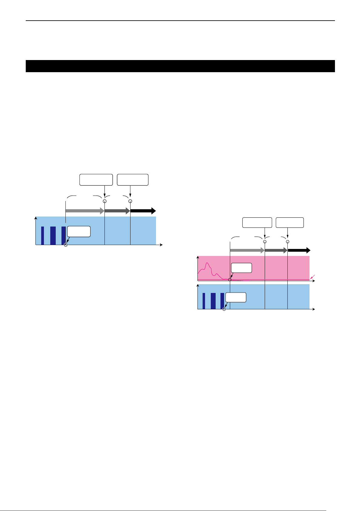
When the transceiver enters the Emergency mode, a
countdown starts. The transceiver counts down during
the Reminder Timer set time.
Before the Reminder Timer set time expires, the
transceiver transmits an Emergency call once, or
repeatedly*, on the specied Emergency channel.
If no Emergency channel is specied, the Emergency
call is made on the previously selected channel.
* Depending on the presetting.
L The transceiver automatically transmits a repeat
Emergency call until the [Back] key is pushed, it
receives an acknowledgement, or until a user turns
OFF the transceiver.
L If the transceiver is set for Silent operation, it
transmits an Emergency call without a beep
sounding or the status indicator lighting.
The transceiver enters the Emergency mode through
the following functions:
• The [Emergency] key
When a user holds down [Emergency] for the Emer
SW ON Timer preset time.
L If a user holds down [Emergency] for the Emer SW
OFF Timer set time before the Reminder Timer set
time expires, the Emergency mode is canceled.
(Example)
• Emer SW ON Timer: 10 seconds
• Reminder Timer: 10 seconds
Enters the
Emergency mode.
10 sec. 10 sec.
ON Timer
[Emer]
Operation
4-3
Sends an
Emergency call.
Reminder
Timer
Time
☞ Continued on the next page.
Emergency
Timer
Page 42

4
ADVANCED OPERATION
Emergency call
D Transmitting an Emergency call (Continued)
The transceiver enters the Emergency mode through
the following functions:
• The Man Down function
When the transceiver leans past the preset angle for
the ON Timer preset time.
L If a user raises the transceiver back from the preset
angle towards the vertical position before the
Reminder Timer set time expires, the Emergency
mode is canceled.
(Example)
• ON Timer: 10 seconds
• Reminder Timer: 10 seconds
• Angle: 45 degrees
Enters the
Emergency mode.
10 sec. 10 sec.
ON Timer
Sends an
Emergency call.
Reminder
Timer
Emergency
Timer
With Stationary
z The transceiver leans past the preset angle for the
ON Timer preset time.
AND
z The transceiver is detected as stationary (no
motion) for the ON Timer set time.
L If a user raises the transceiver back from the preset
angle towards the vertical position, or when the user
moves the transceiver before the Reminder Timer
set time expires, the Emergency mode is canceled.
(Example)
• ON Timer: 10 seconds
• Reminder Timer: 10 seconds
• Angle: 45 degrees
Enters the
Emergency mode.
Sends an
Emergency call.
Angle
Pasts 45 degrees
Time
Angle Acceleration
10 sec. 10 sec.
ON Timer
No motion is
detected.
Pasts 45 degrees
Time
Reminder
Timer
Emergency
Timer
Stationary
Sensitivity
4-4
Page 43
4
ADVANCED OPERATION
Emergency call
D Transmitting an Emergency call (Continued)
The transceiver enters the Emergency mode through
the following functions:
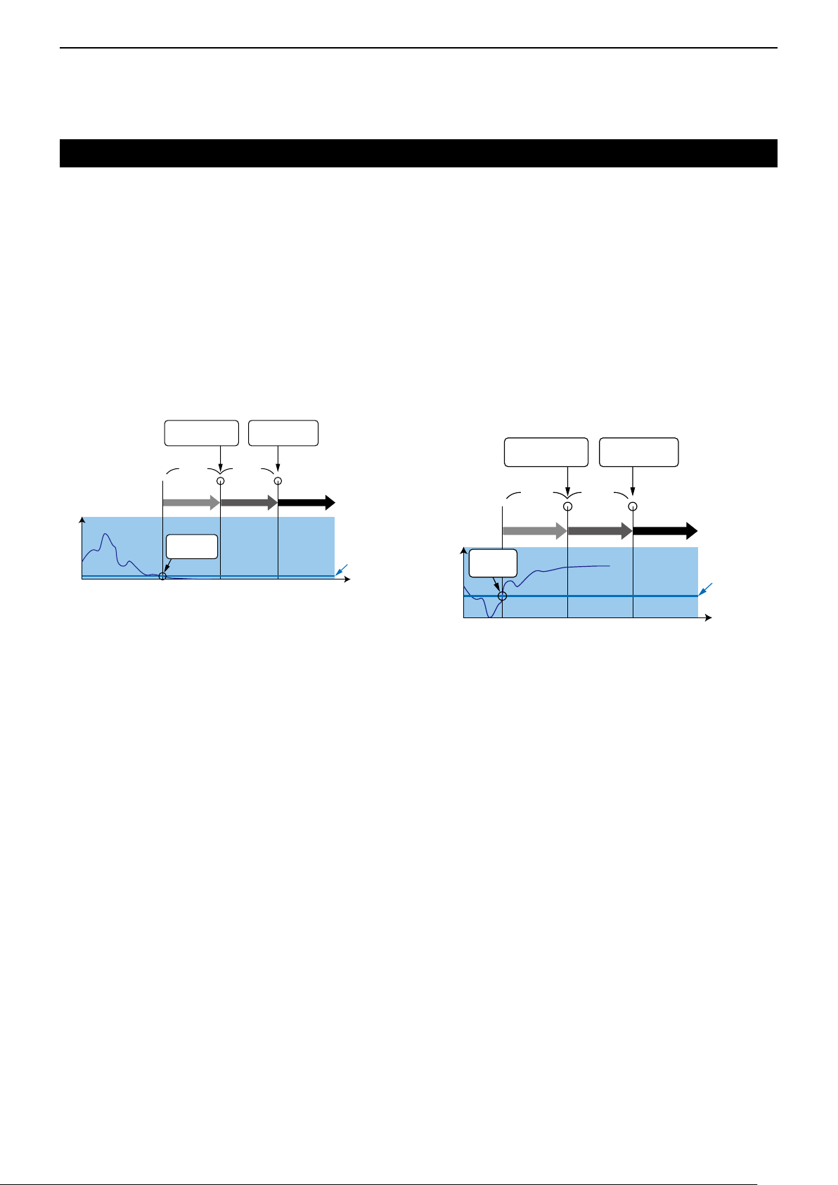
• The Lone Worker function
When no operation occurs for the ON Timer preset time.
L If a user pushes any key before the Reminder Timer
set time expires, the Emergency mode is canceled.
(Example)
• ON Timer: 60 minutes
• Reminder Timer: 60 seconds
Enters the
Emergency mode.
60 min.
ON Timer
Sends an
Emergency call.
60 sec.
Reminder
Timer
Emergency
Timer
With Stationary
z When no operation occurs for the ON Timer preset
time.
AND
z The transceiver is detected as stationary (no
motion) for the ON Timer set time.
L If a user pushes any key, or moves the transceiver
before the Reminder Timer set time expires, the
Emergency mode is canceled.
(Example)
• ON Timer: 60 minutes
• Reminder Timer: 60 seconds
Operation
[PTT][PTT][PTT]
No operation
is detected.
Time
Operation Acceleration
[PTT][PTT][PTT]
No motion is
detected.
No operation
is detected.
Enters the
Emergency mode.
60 min.
ON Timer
Time
Sends an
Emergency call.
60 sec.
Reminder
Timer
Emergency
Timer
Stationary
Sensitivity
4-5
Page 44
4
ADVANCED OPERATION
Emergency call
D Transmitting an Emergency call (Continued)
The transceiver enters the Emergency mode through
the following functions:
• The Stationary Detection function
When the transceiver is detected as being stationary
(no motion) for the ON Timer preset time.
L If a user moves the transceiver during the Reminder
Timer set time, the Emergency mode is canceled.
(Example)
ON Timer: 60 seconds
Reminder Timer: 60 seconds
Acceleration
Enters the
Emergency mode.
60 sec. 60 sec.
ON Timer
No motion is
detected.
Time
Sends an
Emergency call.
Reminder
Timer
Emergency
Timer
Stationary
Sensitivity
• The Motion Detection function
When the transceiver continuously moves for the ON
Timer preset time.
L If a user holds down [Emergency] for the Emer SW
OFF Timer set time, before the Reminder Timer set
time expires, the Emergency mode is canceled.
(Example)
Motion Detection Timer: 10 seconds
Reminder Timer: 10 seconds
Enters the
Emergency mode.
ON Timer
Motion is
detected.
Acceleration
10 sec.10 sec.
Reminder
Timer
Time
Sends an
Emergency call.
Emergency
Timer
Motion
Sensitivity
4-6
Page 45

4
ADVANCED OPERATION
Scrambler
The Voice Scrambler function provides private
communication between stations.
Push [Scrambler/Encryption] to toggle the Scrambler
function ON or OFF.
• “ ” is displayed when the Scrambler function is ON.
L When the Scrambler function is ON, push [PTT] to make
a private communication between stations by using a
scrambled code.
Network Access Code (NAC)
NAC is a signaling system designed for digital radio
communications.
When a channel is set up with an NAC, the squelch
will open only when a call containing a matching NAC
is received.
If a call containing a different NAC is made on the
same channel a user is using, a user will not hear the
call.
4-7
Page 46

4
ADVANCED OPERATION
AquaQuake™ Water Draining function (for the Portable type transceiver)
By vibrating the speaker, the AquaQuake Water
Draining function clears water from the speaker grill to
maintain clear audio.
1. Hold down [AquaQuake] to turn ON the
AquaQuake water draining function.
• A low frequency vibration is generating to remove
water from the speaker grill.
• Water in the speaker grill may mufe the sound
coming from the speaker.
2. Release the key to turn OFF the function.
NOTE:
• After the specied period of time expires, this
function automatically stops, even if a user
continues to hold down this key.
• This key works for only the internal speaker.
4-8
Page 47

Section 5
SCAN OPERATION
Starting a Scan ....................................................................... 5-2
Canceling a Scan ................................................................... 5-3
Selecting a Scan list ............................................................... 5-4
Setting or clearing a Scan tag ................................................ 5-5
5-1
Page 48

5
SCAN OPERATION
Starting a Scan
A Scan checks for signals on each channel and stops
when a signal is received.
NOTE: Two or more channels must be preset to start
a Scan.
<Key operation>
Push [Scan Start/Stop] to start a Scan.
• “ ” blinks.
When a signal is detected, the Scan pauses on the
channel until the signal disappears, and then the Scan
resumes.
<Menu operation>
(Menu > Channel/Scan > Scan Start/Stop)
1. Push [Menu] to display the Menu screen.
2. Push [Left] or [Right] to select “Channel/Scan,”
then
push [OK].
3. Push [Up] or [Down] to select “Scan Start/Stop,”
then
push [OK].
4. Push [Up] or [Down] to select “ON,” then push
[OK].
• The Scan starts.
When a signal is detected, the Scan pauses on the
channel until the signal disappears, then the Scan
resumes.
5. Hold down [Back] for 1 second to return to the
standby screen.
• “ ” blinks while scanning.
5-2
Page 49

5
SCAN OPERATION
Canceling a Scan
<Key operation>
While scanning, push [Scan Start/Stop] to stop a
Scan.
• “ ” disappears.
<Menu operation>
(Menu > Channel/Scan > Scan Start/Stop)
1. Push [Menu] to display the Menu screen.
2. Push [Left] or [Right] to select “Channel/Scan,”
then
push [OK].
3. Push [Up] or [Down] to select “Scan Start/Stop,”
then
push [OK].
4. Push [Up] or [Down] to select “OFF,” then push
[OK].
• The Scan stops.
• “Scan Start/Stop OFF” is briefl y displayed.
5. Hold down [Back] for 1 second to return to the
standby screen.
• “ ” disappears.
5-3
Page 50

5
SCAN OPERATION
Selecting a Scan list
You can select a Scan list to be scanned.
Channels included in the selected Scan list are
scanned during a scan.
When selecting a zone type Scan list, the channels
that are in the same zone as the Scan start channel
will be scanned.
<Key operation>
1. Hold down [Scan Start/Stop] for 1 second to
display the “Scan List” screen.
2. Push [Up] or [Down] to select a list, then
[OK].
push
<Menu operation>
(Menu > Channel/Scan > Scan List)
1. Push [Menu] to display the Menu screen.
2. Push [Left] or [Right] to select “Channel/Scan,”
then
push [OK].
3. Push [Up] or [Down] to select “Scan List,” then
push [OK].
• Displays the “Scan List” screen.
4. Push [Up] or [Down] to select a list, then push
[OK].
5. Hold down [Back] for 1 second to return to the
standby screen.
5-4
Page 51

5
SCAN OPERATION
Setting or clearing a Scan tag
You can set or clear a Scan tag to or from a channel in
a Scan list.
The Scan tag channel is a target channel during a
Scan.
<Key operation>
In a current Scan list:
1. Select a channel. (p. 3-4)
2. Push [Scan Add/Del (Tag)] to set or clear a Scan
tag to or from the channel.
• “ ” is displayed for a Scan tag channel.
When setting a Scan tag:
When clearing a Scan tag:
In a selected Scan list:
1. Select a channel. (p. 3-4)
2. Hold down [Scan Add/Del (Tag)] for 1 second to
display the “Scan tag” screen.
3. Push [Up] or [Down] to select a Scan list.
4. Push [OK] to set or clear a Scan tag to or from the
channel.
When setting a Scan tag:
When clearing a Scan tag:
5. Hold down [Back] for 1 second to return to the
standby screen.
5-5
Page 52

5
SCAN OPERATION
Setting or clearing a Scan tag (Continued)
<Menu operation>
(Menu > Channel/Scan > Scan tag)
1. Select a channel. (p. 3-4)
2. Push [Menu] to display the Menu screen.
3. Push [Left] or [Right] to select “Channel/Scan,”
then
push [OK].
4. Push [Up] or [Down] to select “Scan tag,” then
push [OK].
• Displays the “Scan tag” screen.
5. Push [Up] or [Down] to select a list, then push
[OK].
When setting a Scan tag:
When clearing a Scan tag:
6. Hold down [Back] for 1 second to return to the
standby screen.
5-6
Page 53

Section 6
MENU SCREEN
Menu screen description ........................................................ 6-2
D Using the Menu screen ................................................... 6-2
Menu items ............................................................................. 6-3
Channel/Scan ......................................................................... 6-8
Signaling/Call.......................................................................... 6-9
Trunking ................................................................................6-10
Functions ...............................................................................6-11
GPS ...................................................................................... 6-12
Voice Rec .............................................................................6-13
Audio Setting ........................................................................ 6-14
SD Card ................................................................................ 6-15
Bluetooth .............................................................................. 6-16
Clock..................................................................................... 6-17
Vibration ...............................................................................6-17
Sensor .................................................................................. 6-18
Display .................................................................................. 6-18
Utility ..................................................................................... 6-19
Information............................................................................ 6-20
Control Head ........................................................................ 6-21
6-1
Page 54

6
MENU SCREEN
Menu screen description
The user can open the “Menu” screen using the
[Menu] key.
In the “Menu” screen, the items are categorized.
Depending on the presetting, the user can select
various functions and set the transceiver settings in
the “Menu” screen.
L The “Menu” screen has 2 display types: Icon type
and List type. In this operating guide, the Icon type
is used for the main illustration.
NOTE: The language displayed on the “Menu”
screen is set to English by default, but a dealer
can change it to another language using the
programming software.
In this case, the item names are displayed on the
screen in the language set by the dealer, instead of
z Categories
English.
1
Channel
/Scan
TrunkingSignaling
/Call
*
“Menu” screen
Icon type
List type
Voice RecGPS
Setting
BluetoothFunctions SD CardAudio
: Push [Right]
: Push [Left]
Display ClockVibrationSensorUtilityControl
Head
Information
2
*
D Using the Menu screen
Example: Starting a Scan
1. Push [Menu] to display the Menu screen.
2. Push [Left] or [Right] to select “Channel/Scan,”
then
push [OK].
3. Push [Up] or [Down] to select “Scan Start/Stop,”
then
push [OK].
*1 For only the revision 2.00 or later.
*2 For only the mobile type.
4. Push [Up] or [Down] to select “ON,” then push
[OK].
• The Scan starts.
5. Hold down [Back] for 1 second to return to the
standby screen.
6-2
Page 55

6
MENU SCREEN
Menu items
In the Menu screen, the items are categorized, as shown below.
Channel/Scan
Signaling/Call
C.Tone CH Select
Sets the Continuous tone channel.
Compander
Turns the Compander function ON or OFF.
Priority A CH
Selects the Priority A channel.
Prio A (Rewrite)
Sets a current channel as the Priority A channel.
Priority B CH
Selects the Priority B channel.
Prio B (Rewrite)
Sets a current channel as the Priority B channel.
NAC CH Select
Sets the NAC channel.
RF Power
Selects the output power for each channel.
Scan Tag (Scan Add/Del(Tag))
Sets or clears a Scan tag to or from a channel in a Scan list.
Scan List
Sets a Scan list to be scanned.
Scan Start/Stop
Starts or cancels a Scan.
Talkgroup Scan*
Starts or cancels a Talkgroup Scan.
Scramble/Encrypt*
Turns the Voice Scrambler/Encryption function ON or OFF.
CKR Select*
Select the Encryption’s Common Key Reference (CKR).
T alk Around
Turns the Talk Around function ON or OFF.
Zone Select
Selects a Zone.
Call Menu
Selects a calling destination and a call type.
Clear Incoming
Clears the received call log from the Incoming list.
Clear Outgoing
Clears the transmit call log from the Outgoing list.
DTMF Autodial
Displays the “DTMF Autodial” screen. The preset DTMF codes are selectable.
Group Select
Displays the “Group Select” screen. The preset Group IDs are selectable.
Incoming
Displays a log of the received calls.
Individual Select
Displays the “Individual Select” screen. The preset Individual IDs are selectable.
Message (Short Message)
Displays the “Message” screen. The preset Messages are selectable.
p. 6-8
p. 6-8
p. 6-8
p. 6-8
p. 6-8
p. 6-8
p. 6-8
p. 6-8
p. 6-8
p. 6-8
p. 6-8
p. 6-8
p. 6-8
p. 6-8
p. 6-8
p. 6-8
p. 6-9
p. 6-9
p. 6-9
p. 6-9
p. 6-9
p. 6-9
p. 6-9
p. 6-9
* For only the revision 2.00 or later.
☞ Continued on the next page
6-3
Page 56

6
MENU SCREEN
Menu items (Continued)
Signaling/Call
(Continued)
Trunking*
Functions
GPS
Outgoing
Displays a log of the transmit calls
Status
Displays the “Status” screen. The preset Status messages are selectable.
Site Alias
Displays the RFSS ID and Site ID, or the Site Alias name if entered.
Site Lock
Lock the transceiver in the current registered site.
Site Select
Select a site.
Site Change Beep
Select whether or not to sound a Site Change Beep.
Band Scan
Turns the Band Scan function ON or OFF.
Internal Hunt List
Enters the Internal Hunt List mode.
Ext CH Sel Mode
Turns the External Channel Select mode ON or OFF.
Hook Scan
Turns the On Hook Scan function ON or OFF. (Mobile only)
Horn
Turns the Horn function ON or OFF. (Mobile only)
Lone Worker
Turns the Lone Worker function ON or OFF.
Public Address
Adjusts the Audio Output level of the connected Public Address (PA). (Mobile only)
RX Speaker
Turns the RX speaker function ON or OFF. (Mobile only)
Surveillance
Turns the Surveillance function ON or OFF.
USB Mode Select
Selects the USB port mode.
VOX
Turns the VOX function ON or OFF.
VOX Delay
Sets the VOX Delay.
VOX Gain
Sets the VOX gain.
Keyset*
Selects a Keyset.
Zeroize*
Zeroize the encryption key data.
Rekey*
Request rekeying.
GPS ON/OFF
Turns the GPS function ON or OFF.
GPS Position (My Position)
Displays the transceiver’s current position.
p. 6-9
p. 6-9
p. 6-10
p. 6-10
p. 6-10
p. 6-10
p. 6-10
p. 6-10
p. 6-11
p. 6-11
p. 6-11
p. 6-11
p. 6-11
p. 6-11
p. 6-11
p. 6-11
p. 6-11
p. 6-11
p. 6-11
p. 6-11
p. 6-11
p. 6-11
p. 6-12
p. 6-12
* For only the revision 2.00 or later.
☞ Continued on the next page
6-4
Page 57

6
MENU SCREEN
Menu items (Continued)
Voice Rec
Audio Setting
SD Card
Bluetooth
Call Recorder
Starts or stops the audio recording.
Play Call Rec (Play Call Record)
Enables the user to play back the recorded audio on the microSD card.
Mic Gain
Sets the microphone sensitivity.
RX Noise Cancel
Selects whether or not to suppress the receive audio noise to make the audio easy to
hear.
TX Noise Cancel
Selects whether or not to suppress the microphone input noise to make the audio easy
to hear.
RX EQ Effect (RX Equalizer Effect)
Selects the RX Equalizer Effect.
RX EQ Edit (RX Equalizer Edit)
Enables the user to edit the RX Equalizer Effect.
TX EQ Effect (TX Equalizer Effect)
Selects the TX Equalizer Effect.
TX EQ Edit (TX Equalizer Edit)
Enables the user to edit the TX Equalizer Effect.
Load Setting <- SD
Loads the transceiver’s settings from a microSD card.
SD Unmount
Unmounts a microSD card.
SD Format
Formats the microSD card.
SD Information
Displays the microSD card capacity and the time remaining for audio recording.
Software Update
Updates the transceiver’s rmware.
Bluetooth
Turns the Bluetooth
Bluetooth Reset
Initializes the Bluetooth unit.
Bluetooth Auto Connect
Select whether or not to automatically connect to the paired Bluetooth device when its
power is turned ON.
Bluetooth Audio Setting
Selects the AF Output device when a Bluetooth headset is connected.
BT Device Info (Bluetooth Device Information)
Displays the installed Bluetooth unit name.
BT Device List (Bluetooth Device List)
Displays the paired Bluetooth devices.
®
function ON or OFF.
p. 6-13
p. 6-13
p. 6-14
p. 6-14
p. 6-14
p. 6-14
p. 6-14
p. 6-14
p. 6-14
p. 6-15
p. 6-15
p. 6-15
p. 6-15
p. 6-15
p. 6-16
p. 6-16
p. 6-16
p. 6-16
p. 6-16
p. 6-16
6-5
☞ Continued on the next page
Page 58

6
MENU SCREEN
Menu items (Continued)
Bluetooth
(Continued)
Clock
Vibration
Sensor
Display
Key Beep (VS-3)
Sets the beep sound when the VS-3
[RWD]) is pushed.
P.Save (VS-3) (Power Save(VS-3))
Selects whether to operate in the Bluetooth headset’s Battery Saving mode when the
Bluetooth headset is connected.
VS-3
PTT Beep (VS-3)
Sets the beep sound when [PTT] is pushed on the VS-3
One-touch PTT
Sets the One-Touch PTT function when the
Waiting Pairing
Enters the pairing request wait mode.
Clock Adjust
Sets the date and time.
Clock Auto Adjust
Selects whether or not to automatically adjust the clock with data from the internal GPS
receiver.
Clock Display
Displays the current time on the transceiver’s LCD.
DST (Daylight Saving Time)
Selects whether or not to use Daylight Saving Time (DST) for the clock.
Opening Vibration
Selects whether or not to vibrate the transceiver when it is turned ON. (Portable only)
Vibration
Turns the Vibration function ON or OFF. (Portable only)
Key Vibration
Selects whether or not to vibrate the transceiver when a user pushes a key.
(Portable only)
Man Down Angle
Sets the Emergency mode detection angle for the Man Down function. (Portable only)
Motion Sense
Sets the acceleration sensor sensitivity to detect whether the user is moving or not, for
the Motion Detection function. (Portable only)
Stationary Sense
Sets the acceleration sensor sensitivity to detect if the user is stationary or not for the
Stationary Detection function. (Portable only)
Backlight
Sets the Key Backlight status.
Brightness
Sets the LCD brightness level.
Dimmer
Sets the LCD dimmer level.
Language
Selects the language type used on the transceiver’s display.
LCD Color Test
Checks whether or not the LCD displays color correctly.
LCD Mode
Sets the LCD Mode.
Bluetooth headset Custom Key ([PLAY]/[FWD]/
Bluetooth headset.
Bluetooth headset is connected.
p. 6-16
p. 6-16
p. 6-16
p. 6-16
p. 6-16
p. 6-17
p. 6-17
p. 6-17
p. 6-17
p. 6-17
p. 6-17
p. 6-17
p. 6-18
p. 6-18
p. 6-18
p. 6-18
p. 6-18
p. 6-18
p. 6-18
p. 6-18
p. 6-18
6-6
Page 59

6
MENU SCREEN
Menu items (Continued)
Utility
Information
Control Head
System Beep Lv (System Beep Level)
Sets the System Beep output level.
Emer Beep Lv (Emergency Beep Level)
Sets the Beep output level when in the Emergency mode.
Key-touch Beep Lv (Key-touch Beep Level)
Sets the Key-touch Beep output level.
Side Tone Lv (Side Tone Beep Level)
Set the Side Tone Beep output level.
Opening Beep Lv (Opening Beep Level)
Sets the Opening Beep output level.
Ringer Lv (Ringer Level)
Sets the Ringer output level.
SQL Level
Sets the squelch level.
Warning Beep Lv (Warning Beep Level)
Sets the Warning Beep output level.
Announce Lv (Announce Level)
Sets the Beep output level for the Channel Announce function.
Battery Info (Battery Information)
Displays the battery voltage.
Comment
Displays the transceiver’s comments.
Firmware Info (Firmware Information)
Displays the transceiver’s rmware information.
Unit ID
Displays the transceiver’s unit ID.
RSSI/BER
Displays the transceiver’s RSSI (Received Signal Strength Indication) level and BER (Bit
Error Rate).
Intercom
Turns the Intercom function ON or OFF. (Mobile only)
Hanger
Turns the Hanger function ON or OFF. (Mobile only)
TX AF Monitor
Turns the TX AF Monitor function ON or OFF. (Mobile only)
SP Link (Speaker Link)
Turns the Speaker Link function ON or OFF. (Mobile only)
Primary Mic
Selects which CONTROL HEAD's microphone to input the audio when using the Auto TX
function or PC commands. (Mobile only)
Head SP Out (Head Speaker Output)
Selects whether or not to output the audio from the CONTROL HEAD or an external
speaker. (Mobile only)
p. 6-19
p. 6-19
p. 6-19
p. 6-19
p. 6-19
p. 6-19
p. 6-19
p. 6-19
p. 6-19
p. 6-20
p. 6-20
p. 6-20
p. 6-20
p. 6-20
p. 6-21
p. 6-21
p. 6-21
p. 6-21
p. 6-21
p. 6-21
6-7
Page 60

6
MENU SCREEN
Channel/Scan
C.Tone CH Select
In the Analog mode
Sets the Continuous tone channel. (p. 3-5)
Compander
In the Analog mode
Turns the Compander function ON or OFF.
This function reduces noise components on the
transmit audio for clear communication.
Priority A CH
Selects the Priority A channel. (p. 3-5)
Prio A (Rewrite)
Sets a current channel as the Priority A channel.
(p. 3-5)
Priority B CH
Selects the Priority B channel. (p. 3-5)
Prio B (Rewrite)
Sets a current channel as the Priority B channel.
(p. 3-5)
NAC CH Select
In the Digital mode
Sets the Network Access Code (NAC) channel.
(p. 3-6)
RF Power
Selects the output power for each channel.
• Options: Low 1, Low 2, High
L “Low 1” is the lowest power level, and “High” is the
highest power level.
L Lower output power during short-range communications
may reduce the possibility of interference to other
stations.
Scan List
Sets a Scan list to be scanned. (p. 5-4)
Scan Start/Stop
Starts or cancels a Scan.
A Scan checks for signals on each channel and stops
when a signal is received.
Talkgroup Scan (For only the revision 2.00 or later.)
Starts or cancels a Talkgroup Scan.
A Talkgroup Scan used to monitor the trunking group’s
communication. The function scans up to 8 Talkgroup
IDs and Memory channels. If the transceiver is out of
range, this item is disabled.
Scramble/Encrypt
In the Analog mode
Turns the Voice Scrambler function ON or OFF.
This function enables private communication between
stations using a Scramble code.
L The same Scramble code must be set in all stations to
communicate.
In the Digital mode (For only the revision 2.00 or later.)
Turns the Encryption function ON or OFF.
This function enables private communication between
stations using an Encryption Key and Key ID.
L The same Encryption Key and Key ID must be set in all
stations to communicate.
CKR Select (For only the revision 2.00 or later.)
Select the Encryption's Common Key Reference
(CKR).
T alk Around
Turns the Talk Around function ON or OFF.
The Talk Around function equalizes the transmit
frequency to the receive frequency, for direct
(Simplex) communication.
Scan Tag
Sets or clears a Scan tag to or from a channel in a
Scan list. (p. 5-5)
Zone Select
Selects a Zone. (p. 3-3)
6-8
Page 61

6
MENU SCREEN
Signaling/Call
Call Menu
In the Analog mode (MDC 1200 only)
Selects a calling destination and a call type (Call
Alert, Radio Check, Stun, Revive, and SelCall).
After selecting, push [PTT] to transmit the call to the
selected destination. (pp. 8-3 ~ 8-6)
In the Digital mode
Selects a calling destination and a call type (Status,
Short Message, Call Alert, Remote Monitor, Radio
Check, Radio Inhibit (Stun/Kill) and Radio Uninhibit
(Revive). After selecting, push [PTT] to transmit the
call to the selected destination. (pp. 7-3 ~ 7-9)
NOTE: When the call type is “Status” or “Short
Message,” you can select or directly enter a
message before transmitting it. After selecting or
entering a message, push [PTT] to transmit it. See
pages 7-4 ~ 7-6 for details.
Clear Incoming
In the Digital mode
Incoming
In the Analog mode (MDC 1200 only)
In the Digital mode
Displays a log of the received Individual call, Call Alert
call, Status message, and Message. (pp. 7-12, 8-7)
Individual Select
In the Digital mode
Displays the “Individual Select” screen. Then, push
[Up] or [Down] to select a Individual ID from the
Individual ID List. After selecting, push [PTT] to send a
Individual call. (p. 7-3)
Message
In the Analog mode (MDC 1200 only)
In the Digital mode
While in the Standby mode, push to display the
“Message List” screen. Then, push [Up] or [Down] to
select a message.
L See pages 7-3, 8-4 for details.
In the Analog mode (MDC 1200 only)
Clears the received call log from the Incoming list.
(p. 7-13)
Clear Outgoing
In the Digital mode
Clears the transmit call log from the Outgoing list.
(p. 7-14)
DTMF Autodial
Displays the “DTMF Autodial” screen. Then, push
[Up] or [Down] to select a DTMF code. After selecting,
push [PTT] to transmit the selected DTMF code.
Group Select
In the Digital mode
Displays the “Group Select” screen. Then, push [Up]
or [Down] to select a Group ID from the Group List.
After selecting, push [PTT] to transmit a Group call.
(p. 7-3)
Outgoing
In the Digital mode
Displays a log of the transmitted Individual calls and
Call Alert calls. (p. 7-14)
Status
In the Analog mode (MDC 1200 only)
In the Digital mode
Push to display the “Status List” screen. Then, push
[Up] or [Down] to select a Status message.
L See pages 7-6, 8-14 for details.
6-9
Page 62

6
MENU SCREEN
Trunking (For only the revision 2.00 or later.)
Site Alias
Displays the RFSS ID and Site ID, or the Site Alias
name if entered. You can enter the Site Alias name on
the Site List screen.
Site Lock
Locks the transceiver in the current registered site.
This function inhibits the transceiver from roaming
other sites.
Site Select
Enter the site select mode.
Editing the RFSS ID:
1. While displaying the site, push [OK] to display its
RFSS ID and the Site ID.
2. Hold down [OK] to enter the editing mode.
3. Push [Up] or [Down] to set.
Connecting to the site:
1. Hold down [OK] to connect to the site.
2. While displaying the site, hold down [OK] to
connect to the site.
Site Change Beep
Select whether or not to sound a beep after
registration and group afliation are successful in the
Trunking system.
Band Scan
Start or cancel the Band Scan.
L This function cannot be used while scanning, transmitting,
or in the Conventional mode.
Internal Hunt List
Displays the Internal Hunt List.
6-10
Page 63

6
MENU SCREEN
Functions
Ext CH Sel Mode
Turns the External Channel Select function ON or
OFF.
When this function is ON, Memory channels are
selectable by only external input.
NOTE: This function is activated when the external
unit is connected to the transceiver. To use the
function, set “MCH Select:1” ~ “MCH Select:
5” to any pins, in the Port Setting screen of the
programming software.
Hook Scan (For the Mobile type)
Turns the On Hook Scan function ON or OFF.
When this function is ON, after putting the microphone
in its hanger (on-Hook), the transceiver automatically
starts scanning.
Horn (For the Mobile type)
Turns the Horn function ON or OFF.
When this function is ON, the HORN terminal of the
D-Sub 25 pin or Option Connector 22 pin is activated
after receiving a call with the Dec EXO or RX EXO
setting is ON.
L This function is useful when the user is away from the
transceiver.
L An external horn is required.
Lone Worker
Turns the Lone Worker function ON or OFF.
When this function is ON, the transceiver
automatically enters the Emergency mode if no
operation occurs during the preset period.
Public Address (For the Mobile type)
Adjusts the Audio Output level of the connected Public
Address (PA).
Surveillance
Turns the Surveillance function ON or OFF.
When this function is ON, beeps are not heard and
the backlight and the Status indicator do not light,
even when a signal is received, or a key is pushed.
USB Mode Select
Selects the USB port mode.
• Data Transfer: Used for setting up the transceiver,
updating the rmware, or using the
PC control command.
• Card Reader: Reads the inserted card contents.
VOX
Turns the VOX function ON or OFF.
When this function is ON, the receive and transmit are
automatically switched by detecting the user’s voice.
NOTE: To use the function, a headset* and a VOX
converter cable are required (user supplied).
*Bluetooth headset is also usable.
VOX Delay
Sets the VOX Delay.
The VOX Delay is the period of time the transceiver
continues transmitting after the user stops speaking,
and then the VOX switches to receive.
• Range: 0.5 ~ 3.0 seconds
NOTE: If you set the time too short, a pause in
a conversation may be regarded as the end of
conversation, and the transceiver will start receiving,
even as the conversation continues.
VOX Gain
Sets the VOX gain.
The VOX function automatically switches between
receive and transmit by detecting the user’s voice.
• Range: 1 ~ 10
L Higher values make the VOX function more sensitive to
sounds.
RX Speaker (For the Mobile type)
Turns the RX speaker function ON or OFF.
When this function is ON, the received audio can be
heard through an external speaker that is connected
to the D-Sub 25 pin connector.
NOTE:
• This function is usable when an external speaker is
connected to the D-Sub 25 pin connector.
• This function is useful when a user is out of the
vehicle.
• The audio output level is linked to the transceiver’s
volume control.
Keyset (For only the revision 2.00 or later.)
Enter the Keyset selection mode.
Push [Up] or [Down] to select the Keyset.
NOTE: To use the function, the optional UT-134
aes/des encryption unit is required.
Zeroize (For only the revision 2.00 or later.)
Zeroize the encryption key data that is programmed
by the key loader.
Rekey (For only the revision 2.00 or later.)
Transmit a Key Management Message (KMM-Hello
command) to a Key Management Facility (KMF) to
request Rekeying.
6-11
Page 64
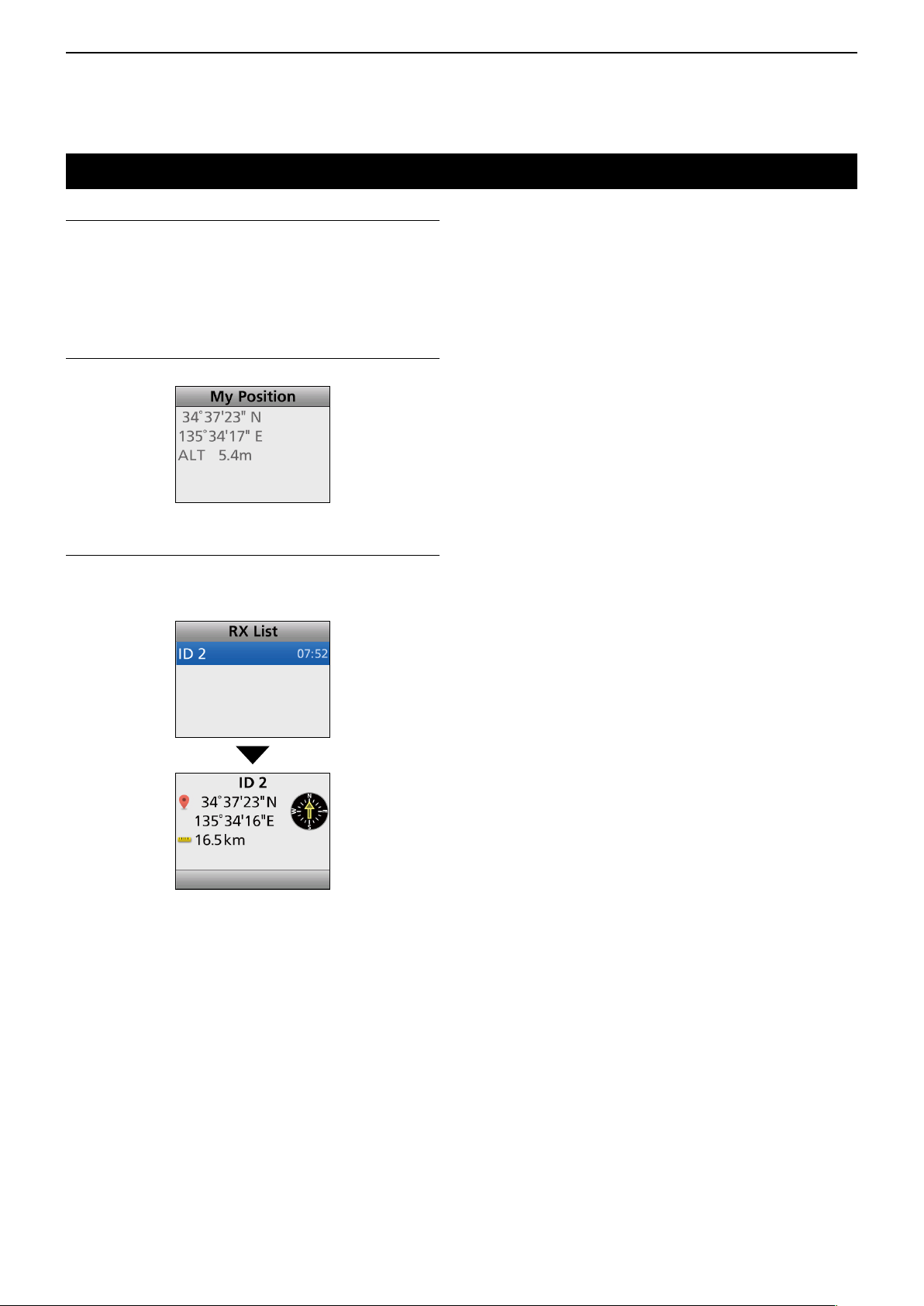
6
MENU SCREEN
GPS
GPS ON/OFF
Turns the GPS function ON or OFF.
When this function is ON, position data from the
internal GPS receiver (Portable) or external GPS
receiver (Mobile) is displayed in the “My Position”
screen.
My Position
Displays the transceiver’s current position.
RX List
Displays the received call log that include position
data. Push [Up] or [Down] to select the log, then push
[OK].
6-12
Page 65

6
MENU SCREEN
Voice Rec
Call Recorder
microSD card is required
z Rec Start
Push [OK] to start the audio recording.
• “ ” is displayed.
InformationL
• While holding down [PTT], “ ” blinks, and the
communication audio is recorded.
• “
” is displayed when the microSD card has no free
space and cannot record audio.
• While recording, “Rec Stop” is displayed in the “Call
Recorder” screen.
• Once the recording has started, the recording will continue,
even if the transceiver is restarted.
• To stop the recording, select “Rec Stop.”
z Rec Stop
Push [OK] to stop the audio recording.
• “ ” disappears.
Play Call Rec
microSD card is required
Do the following steps to play back the recorded audio
on the microSD card.
Select “Play Call Rec,” then push [OK] to display the
folders on the microSD card.
LThese folders contain the audio les.
Playing back
1. Push [Up] or [Down] to select the folder that
includes the desired file to play back, then push
[OK].
2. Push [Up] or [Down] to select the le to play back,
then push [OK].
3. Push [Play] to play back.
• The selected le is played back.
• See page 10-4 for details.
4. Hold down [Back] for 1 second to return to the
standby screen.
NOTE:
• The folder name is automatically created, as shown
in the example below:
Recording date is 2017/7/1
Folder name: 20170701
• The le name is automatically created, as shown in
the example below:
Recording date and time is 2017/7/1 15:30:00
File name: 20170701_153000
• The audio is recorded onto a microSD card, and
saved in the “wav” format. (“wav,” is not displayed
on the transceiver’s screen.)
• The recorded audio can also be played back with a
PC. (p. 10-7)
6-13
Page 66
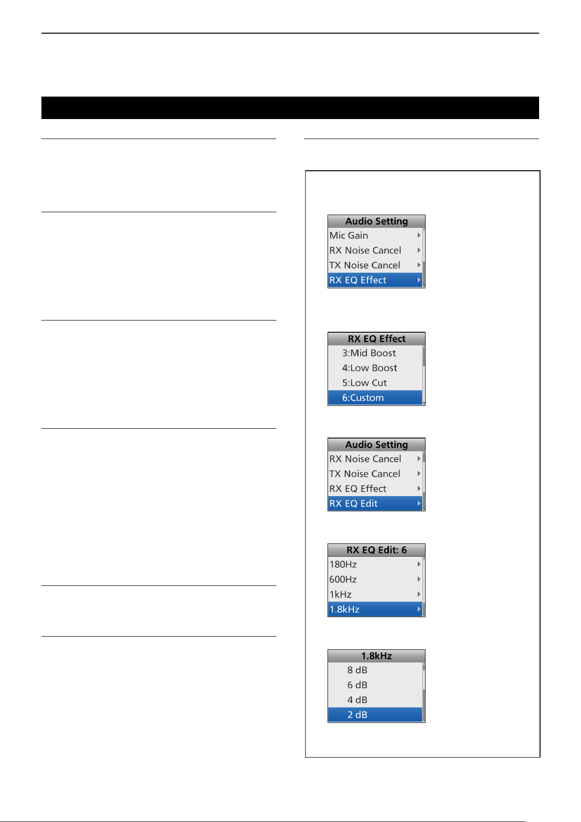
6
MENU SCREEN
Audio Setting
Mic Gain
Sets the microphone sensitivity.
• Range: –8 (Minimum) ~ 5 (Maximum).
L Higher values make the microphone more sensitive to the
user's voice.
RX Noise Cancel
Selects whether or not to suppress the receive audio
noise to make the audio easy to hear.
• OFF: Turns OFF the function.
• 1, 2, or 3: Turns ON the function.
3 levels (1. 2, or 3) are selectable.
L Higher values suppress the audio noise more, but the
audio quality becomes worse.
TX Noise Cancel
Selects whether or not to suppress the microphone
input noise to make the audio easy to hear.
• OFF: Turns OFF the function.
• 1, 2, or 3: Turns ON the function.
3 levels (1. 2, or 3) are selectable.
L Higher values suppress the audio noise more, but the
audio quality becomes worse.
TX Equalizer Edit
Edits the TX Equalizer Effect.
L See below on how to edit.
TIP: How to edit the RX or TX Equalizer Effect
1. Push [Up] or [Down] to select “RX EQ Effect” or
“TX EQ Effect,” then push [OK].
2. Push [Up] or [Down] to select an RX or TX
Equalizer Effect you want to edit, then push
[OK]. (Example: “6: Custom”)
RX Equalizer Effect
Selects the RX Equalizer Effect.
• Flat: Normal audio
• High Boost: Audio that emphasizes the high
frequencies compared to “Flat”
• Mid Boost: Audio that emphasizes the midrange
frequencies compared to “Flat”
• Low Boost: Audio that emphasizes the low
frequencies compared to “Flat”
• Low Cut: Audio that cuts the low frequencies
compared to “Flat”
• Custom: User customized audio
RX Equalizer Edit
Edits the RX Equalizer Effect.
L See to the right on how to edit.
TX Equalizer Effect
Selects the TX Equalizer Effect.
• Flat: Normal audio
• High Boost: Audio that emphasizes the high
frequencies compared to “Flat”
• Mid Boost: Audio that emphasizes the midrange
frequencies compared to “Flat”
• Low Boost: Audio that emphasizes the low
frequencies compared to “Flat”
• Low Cut: Audio that cuts the low frequencies
compared to “Flat”
• Custom: User customized audio
3. Push [Up] or [Down] to select “RX EQ Edit” or
“TX EQ Edit,” then push [OK].
4. Push [Up] or [Down] to select a frequency, then
push [OK]. (Example: “1.8 kHz”)
5. Push [Up] or [Down] to select an AF level, then
push [OK]. (Example: “2 dB”)
6. Hold down [Back] for 1 second to return to the
standby screen.
6-14
Page 67

6
MENU SCREEN
SD Card
Load Setting <- SD
Loads the transceiver’s settings from the microSD
card.
L See “Loading the saved data les onto a microSD card”
for details. (p. 9-5)
SD Unmount
Unmounts the microSD card.
NOTE: Before removing the microSD card, be
sure to electrically unmount the card, when the
transceiver is ON. Otherwise the data may be
corrupted or deleted.
SD Format
Formats the microSD card.
If you use a brand new microSD card, be sure to
format it.
LSee “Formatting the microSD card” for details. (p. 9-4)
NOTE: Before using a microSD card with the
transceiver, be sure to format all microSD cards with
the built-in Format function. This creates a special
folder on the card that you need for operations like
updating the software. Format all cards, including
a brand new microSD card, and even preformatted
cards for PCs or other uses.
SD Information
Displays the microSD card capacity and the time
remaining for voice recording.
L See “Displaying the information of the microSD card” for
details. (p. 9-6)
Software Update
Updates the transceiver’s rmware.
6-15
Page 68

6
MENU SCREEN
Bluetooth
Bluetooth
Turns the Bluetooth function ON or OFF.
• OFF: Turns OFF the function.
• ON: Turns ON the function.
Bluetooth Reset
Initializes the Bluetooth unit.
Only when the Bluetooth function is OFF, initialization
can be done
Bluetooth Auto Connect
Select whether or not to automatically connect to the
paired Bluetooth device when its power is turned ON.
• OFF: Does not connect to the paired device.
• ON: Automatically connects to the last connected
device.
NOTE: The transceiver connects to the last
connected device, if the connecting operation is
performed on the device side, even if this item is set
to OFF.
Bluetooth Audio Setting
Selects the AF Output device when a Bluetooth
headset is connected.
• BT Only: Sets the Bluetooth headset as the AF
Output device.
• BT & SP: Sets the Bluetooth headset and the
transceiver’s speaker as the AF Output
devices.
P.Save (VS-3)
Selects whether to operate in the Bluetooth headset’s
Battery Saving mode when the optional VS-3
Bluetooth
Save is activated, the user cannot use the VOX
function.
NOTE: When a third-party headset or a data device
is connected, this function is automatically set to
OFF, even if this item is set to ON.
• OFF: Turns OFF the function.
• ON: The Power Save mode is enabled when no
PTT Beep (VS-3)
Sets the beep sound when [PTT] is pushed on the
optional VS-3 Bluetooth
• OFF: No beep sounds.
• ON: A beep sounds.
One-touch PTT
Sets the One-Touch PTT function when the Bluetooth
headset is connected. The function enables a user to
transmit without continuously holding down [PTT].
NOTE: When a third-party headset is connected, this
function may automatically be set to ON, even if this
item is set to OFF.
headset is connected. When the Power
communication or operation is performed for
120 seconds.
headset.
BT Device Info
Displays the installed Bluetooth unit name, address,
supported prole, and its version information.
BT Device List
Displays the paired Bluetooth devices.
To nd other Bluetooth device, select “Find Device.”
LSee pages 11-4 and 11-7 for details.
Key Beep (VS-3)
Sets the beep sound when the optional VS-3
Bluetooth
[RWD]) is pushed.
• OFF: No beep sounds.
• ON: A beep sounds.
headset Custom Key ([PLAY]/[FWD]/
• OFF: Push [PTT] to transmit, then release to
receive.
• ON: Push [PTT] to transmit, then push again to
receive.
Waiting Pairing
Enters the pairing request wait mode. The transceiver
waits for a pairing request from a Bluetooth device.
6-16
Page 69

6
MENU SCREEN
Clock
Clock Adjust
z Date
Sets the date (Year/Month/Day).
(The day of the week is automatically set.)
• Range: Year 2000 ~ 2099, Month/Day 1-1 ~ 12-31
z Time
Sets the current time.
(The time is displayed in the 24 hour format.)
• Range: 00:00:00 ~ 23:59:59 (in 1 second steps)
Clock Auto Adjust
Selects whether or not to automatically adjust the
clock with data from the GPS receiver.
Clock Display
Displays the current time on the transceiver’s LCD.
DST
Selects whether or not to use Daylight Saving Time
(DST) for the clock.
Vibration
Opening Vibration (For the Portable types)
Selects whether or not to vibrate the transceiver when
it is turned ON.
L To use this function, the Vibration function must be turned
ON, in advance.
• OFF: Turns OFF the vibration.
• Pattern 01: The transceiver vibrates for 5
seconds.
• Pattern 02: The transceiver vibrates for 1
second three times.
• Pattern 03: The transceiver vibrates for 0.5
seconds four times.
• Pattern 04: The transceiver vibrates for 0.3
seconds eight times.
• Pattern 05 to 16: The transceiver vibrates, according
to the customized pattern.
NOTE: You can customize the Vibration pattern,
Vibration Repeat, and Interval time using the
programming software.
Vibration (For the Portable types)
Turns the Vibration function ON or OFF.
To vibrate the transceiver, set each Vibration setting to
ON using the programming software.
Depending on the Vibration setting, the transceiver
may vibrate:
• When a call that includes a matching 2-Tone code is
received.
• When a Call Alert is received.
• When a Short Message is received.
• When a Status call that includes a matching status
number is received.
• When a user pushes a key.
• While in the Low Battery 1 state.
• While in the Low Battery 2 state.
• While in the Surveillance mode.
Key Vibration (For the Portable types)
Selects whether or not to vibrate the transceiver when
a user pushes a key.
L To use this function, the Vibration function must be turned
ON, in advance.
6-17
Page 70

6
Walking (slow)
Sensitivity Level
For Stationary
• Sensitivity example
MENU SCREEN
Sensor
Man Down Angle (For the Portable types)
Sets the Emergency mode detection angle for the
Man Down function. If the transceiver leans past the
set angle for the ON Timer time period, the transceiver
enters the Emergency mode, and then a countdown
starts.
• Options: 45, 60, or 75 degrees
Motion Sense (For the Portable types)
Sets the acceleration sensor sensitivity to detect
whether the user is moving or not, for the Motion
Detection function. This setting is for the Motion
Detection function, and it determines the acceleration
threshold level to activate the Motion Detection Timer.
• Range: 1 (high sensitivity) ~ 10 (low sensitivity).
L If you set a lower level, the transceiver will enter the
Emergency mode more easily.
Stationary Sense (For the Portable types)
Sets the acceleration sensor sensitivity to detect if the
user is stationary or not for the Stationary Detection
function. This setting is used for the Stationary
Detection function, and it determines the acceleration
threshold level to activate the Stationary Detection’s
ON Timer (Sec).
• Range: 1 (high sensitivity) ~ 10 (low sensitivity).
L If you set at a higher level, the transceiver will enter the
Emergency mode more easily.
Display
Backlight
Sets the Key Backlight status.
For the Portable types
• OFF: Turns the display backlight continuously OFF.
• Auto: When any key except [PTT] is pushed, the
backlight lights for 5 seconds.
• ON: Turns the backlight continuously ON.
For the Mobile type
• OFF: Turns the display backlight continuously OFF.
• Auto: Turns the backlight continuously ON with the
Brightness setting level.
When the Dimmer terminal of the D-Sub 25 pin
or Option Connector 22 pin is activated, the
backlight lights dimly with the Dimmer setting
level.
• ON: Turns the backlight continuously ON with the
Brightness setting level.
Brightness
Sets the LCD brightness level.
• Range: 0 (the lowest) ~ 7 (the highest)
Dimmer
Sets the LCD dimmer level.
• Range: 0 (the lowest) ~ 7 (the highest)
Sensitivity For Motion Sensitivity
Desk Work
Key Operation
Walking (fast)
Running
10
9
8
7
6
5
4
3
2
1
NOTE: It is recommended to be the Dimmer level
lower than the Brightness level.
Language
Selects the language type used on the transceiver's
display.
• English: The contents are displayed in English.
• Other: The contents are displayed in a language
other than English.
LCD Color Test
Checks whether or not the LCD displays color
correctly.
LCD Mode
Sets the LCD Mode.
• Day: The LCD is set to the Day mode.
The Day mode is for daytime operation, and
the display backlight color is set to white.
• Night: The LCD is set to the Night mode.
The Night mode is for nighttime operation,
and the display backlight color is set to black.
6-18
Page 71

6
MENU SCREEN
Utility
System Beep Lv
Sets the System Beep output level.
The beep sounds when connecting to or blocked from
the System. When a Linked option is selected, the
beep level is adjustable with [VOL].
• Range: 1 ~ 5, 1 (Linked) ~ 5 (Linked), or OFF
NOTE: The lockout timer and TOT beeps cannot be
turned OFF.
Emer Beep Lv
Sets the Beep output level when in the Emergency
mode.
When a Linked option is selected, the beep level is
adjustable with [VOL].
• Range: 1 ~ 5, 1 (Linked) ~ 5 (Linked), or OFF
Key-touch Beep Lv
Sets the Key-touch Beep output level.
When a Linked option is selected, the beep level is
adjustable with [VOL].
• Range: 1 ~ 5, 1 (Linked) ~ 5 (Linked), or OFF
Warning Beep Lv
Sets the Warning Beep output level.
The Warning Beep sounds when:
• The battery is exhausted.
• An empty channel is selected.
• The Encryption key fails.
When a Linked option is selected, the beep level is
adjustable with [VOL].
• Range: 1 ~ 5, 1 (Linked) ~ 5 (Linked), or OFF
Announce Lv
Sets the Beep output level for the Channel Announce
function.
The transceiver announces the selected channel
number.
When a Linked option is selected, the beep level is
adjustable with [VOL].
• Range: 1 ~ 5, 1 (Linked) ~ 5 (Linked), or OFF
Side Tone Lv
Set the Side Tone Beep output level.
2-Tone or DTMF code signals are output as the Side
Tone Beeps. When a Linked option is selected, the
beep level can be adjusted with [VOL].
• Range: 1 ~ 5, 1 (Linked) ~ 5 (Linked), or OFF
Opening Beep Lv
Sets the Opening Beep output level.
When a Linked option is selected, the beep level is
adjustable with [VOL].
• Range: 1 ~ 5, 1 (Linked) ~ 5 (Linked), or OFF
Ringer Lv
Sets the Ringer output level.
When a Linked option is selected, the Ringer level is
adjustable with [VOL].
• Range: 1 ~ 5, 1 (Linked) ~ 5 (Linked), or OFF
SQL Level
Sets the squelch level.
• Range: 0 (open) ~ 9 (tight)
6-19
Page 72

6
MENU SCREEN
Information
Battery Info
Displays the battery voltage.
Comment
Displays the transceiver’s comment.
The comment 1 is displayed on the rst screen
(Portable) or upper line (Mobile), and the comment
2 is on the second screen (Portable) or lower line
(Mobile).
Firmware Info
Displays the transceiver’s rmware information.
When an optional unit is installed, you can also check
the unit information. Depending on the installed unit,
only the name may be displayed.
Unit ID
Displays the transceiver’s unit ID.
RSSI/BER
Displays the transceiver’s RSSI (Received Signal
Strength Indication) level and BER (Bit Error Rate).
6-20
Page 73

6
MENU SCREEN
Control Head
NOTE: These settings are settable only when
connecting 2 control heads using the RMK-7
dual-head separation kit or HM-218 hand
microphone*.
* RMK-5 separation kit is required to connect to the
transceiver.
Intercom (For the Mobile type)
Turns the Intercom function ON or OFF.
When this function is ON, the users can communicate
each other through their control head’s microphones.
L While communicating using the Intercom function, you
can use only [PTT] and [VOL].
1. Select “Intercom,” and then push [OK].
• The Intercom function is ON.
2. Hold down or release [PTT] to communicate.
3. Push [OK] to turn the Intercom function OFF.
Hanger (For the Mobile type)
Selects which control head, or simply select both
control heads, to automatically start scanning after
putting the microphone in the hanger (on-Hook).
L To use this function, turn ON the Hook Scan function in
the “Functions” category.
L Other Hanger actions can be set in the CS-F7500
programming software.
• HEAD 1 & HEAD 2: Automatically starts scanning
after putting both microphones
in their hangers.
• HEAD 1: Automatically starts scanning
after putting the microphone in
the CONTROL HEAD 1 hanger.
• HEAD 2: Automatically starts scanning
after putting the microphone in
the CONTROL HEAD 2 hanger.
Primary Mic (For the Mobile type)
Selects which control head’s microphone to use when
transmitting without pushing [PTT], such as when
using the Auto TX function or PC commands.
• Options: HEAD 1, HEAD 2
Head SP Out (For the Mobile type)
Selects whether or not to output the audio from the
control head.
L The user can individually set to each control head, and
also the HM-218.
• OFF: The audio is not output from the control head’s
front speaker or from the HM-218.
• ON: The audio is output from the control head’s
front speaker or from the HM-218.
TX AF Monitor (For the Mobile type)
Turns the TX AF Monitor function ON or OFF.
When this function is ON, the user can monitor the
audio that is transmitted on the other control head.
SP Link (For the Mobile type)
Turns the SP Link function ON or OFF.
When this function is ON, the audio volume settings
between the two control heads are linked.
• OFF: The audio volume settings are not linked,
and are individually set at each control
head.
• HEAD 1: The audio volume settings are linked, and
are equally set on CONTROL HEAD 1.
• HEAD 2: The audio volume settings are linked, and
are equally set on CONTROL HEAD 2.
6-21
Page 74

Section 7
APCO P25 MODE OPERATION
General ................................................................................... 7-2
Transmitting a call ..................................................................7-3
D Transmitting an Individual call ......................................... 7-3
D Transmitting a Talkgroup call .......................................... 7-3
D Transmitting a Status Message ...................................... 7-4
D Transmitting a Short Message ........................................ 7-5
D Transmitting a Call Alert call ...........................................7-6
D Transmitting a Status Query call ..................................... 7-6
D Transmitting a Remote Monitor call ................................ 7-7
D Transmitting a Radio Check call ..................................... 7-7
D Transmitting a Radio Inhibit call ...................................... 7-8
D Transmitting a Radio Uninhibit call ................................. 7-8
D Transmitting a Phone call ............................................... 7-9
D Transmitting an Emergency call ..................................... 7-9
Receiving a call .................................................................... 7-10
D Receiving an Individual call .......................................... 7-10
D Receiving a Group call .................................................. 7-10
D Receiving a Status message ........................................ 7-10
D Receiving a Short message .......................................... 7-10
D Receiving a Call Alert call .............................................7-10
D Receiving a Status Query call ....................................... 7-10
D Receiving a Remote Monitor call .................................. 7-10
D Receiving a Radio Check call ....................................... 7-10
D Receiving a Radio Inhibit call .........................................7-11
D Receiving a Phone call ..................................................7-11
D Receiving an Emergency call ........................................7-11
Incoming list.......................................................................... 7-12
D Displaying the Incoming list .......................................... 7-12
D Deleting the Incoming list .............................................. 7-13
Displaying the Outgoing list .................................................. 7-14
D Displaying the Outgoing list .......................................... 7-14
D Deleting the Outgoing list .............................................. 7-14
Encryption function ............................................................... 7-15
7-1
Page 75

7
APCO P25 MODE OPERATION
General
APCO Project-25 (P25) is designed for public safety
digital radio, and allows you to make a call to a
specic station (Individual call) or to a particular group
(Talkgroup call) in the Conventional mode.
Other P25 transceivers on the channel will not listen in
on a call that does not match their Individual/Talkgroup
group ID or Network Access Code (NAC).
Moreover, the following functions and calls are
available: Call Alert function, Radio Inhibit/Uninhibit
function, Remote Monitor function, Radio Check
function, Status Message, Short Message, Status
Query, Phone Call and Emergency Call function.
NAC matching is not necessary for the above
functions and calls.
Each transceiver has a unique ID, and it allows
to be substituted with an alphanumeric name, if
programmed.
You can use this ID (or name) to select a target station
to call, and the ID (or name) of the target station is
displayed after receiving a call.
7-2
Page 76

7
programming software
programming software
APCO P25 MODE OPERATION
Transmitting a call
APCO P25 mode operation enables you to make
a call to a speci c station (Individual call) or to a
particular group (Group call). Other digital mode
transceivers on the channel will not receive a call that
does not match their Individual or Talkgroup ID and/or
Network Access Code (NAC).
D Transmitting an Individual call
Individual call enables to make a call to a speci c
station, and it provides private communication.
(Menu > Signaling/Call > Individual Select)
1. Push [Menu] to display the Menu screen.
2. Push [Left] or [Right] to select “Signaling/Call,”
then
push [OK].
3. Push [Up] or [Down] to select “Individual Select,”
then
push [OK].
D Transmitting a Talkgroup call
A Talkgroup call enables to make a call to a speci c
Talkgroup only.
The Talkgroup ID ‘65535’ is used for the All Call.
(Menu > Signaling/Call > Group Select)
1. Push [Menu] to display the Menu screen.
2. Push [Left] or [Right] to select “Signaling/Call,”
then
push [OK].
3. Push [Up] or [Down] to select “Group Select,” then
push [OK].
4. Select the target Talkgroup, then push [PTT] to
transmit a Talkgroup call.
4. Select the target Individual station, then push
[PTT] to transmit an Individual call.
5. Hold down [PTT] to speak.
6. Release [PTT] to receive.
NOTE: If the following settings are con gured
using the CS-F7500
Individual ID (or name) is displayed while receiving.
( Digital > Option > Individual Option >
Unit ID Display on Receive)
( Digital > Option > Talkgroup Option >
Unit ID Display on Receive)
TIP: Push [Individual] to directly display the
“Individual Select” screen in step 4 above.
, the
5. Hold down [PTT] to speak.
6. Release [PTT] to receive.
NOTE: If the following settings are con gured
using the CS-F7500
Talkgroup ID (or name) is displayed:
• When the operating channel or zone is changed.
• When [PTT] is pushed.
• While receiving.
( Digital > Option > Talkgroup Option >
Talkgroup Display on Mode Change,
Talkgroup Display on PTT,
Talkgroup Display on Receive)
TIP: Push [Group] to directly display the “Group
Select” screen in step 4 above.
, the
7-3
Page 77
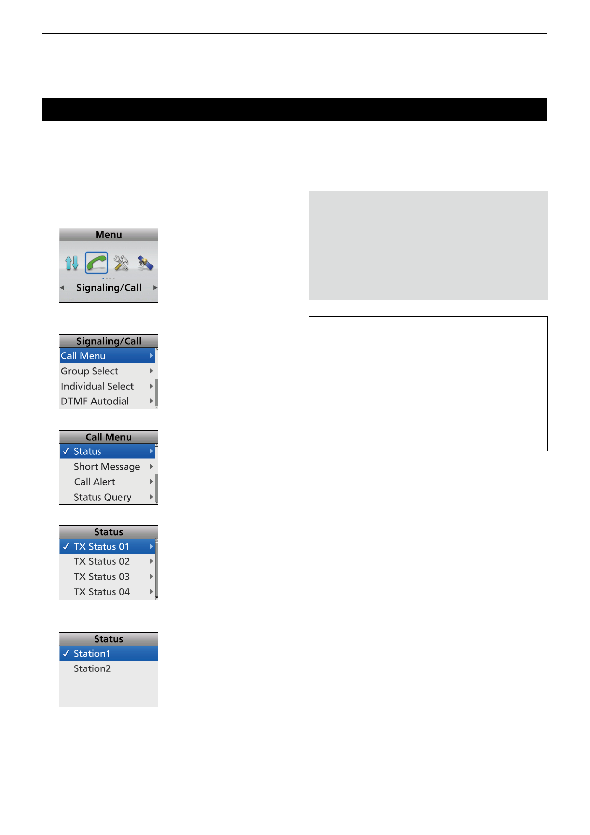
7
programming software
APCO P25 MODE OPERATION
Transmitting a call (Continued)
D Transmitting a Status Message
You can transmit a preset simple message.
A voice signal cannot be sent at the same time.
(Menu > Signaling/Call > Call Menu)
1. Push [Menu] to display the Menu screen.
2. Push [Left] or [Right] to select “Signaling/Call,”
then
push [OK].
3. Push [Up] or [Down] to select “Call Menu,” then
push [OK].
4. Select “Status,” then
push [OK].
NOTE: If the following settings are con gured using
the CS-F7500
message can be automatically transmitted when the
transceiver is turned ON or OFF.
Set the Status message to be transmitted in
“Power ON Status” or “Power OFF Status” item,
respectively.
Set the target station ID in “Power Status ID.”
(Digital > Status > Status Setting)
TIP:
• You can also transmit a Status message through
“Status.”
(Menu > Signaling/Call > Status)
• Push [Call Menu] to directly display the “Call
Menu” screen in step 4 to the left.
• Push [Status] to directly display the “Status”
screen in step 5 to the left.
• Hold down [Status] for 1 second transmit the
preset Status Message to the currently selected
destination.
, the Status
5. Select a Status Message, then
6. Select the target Individual station, then push
[PTT] to transmit the message.
• “Success” is displayed after receiving an
acknowledgment from the target station.
• “Failed” is displayed if the target station does not send
back an acknowledgment.
push [OK].
7-4
Page 78
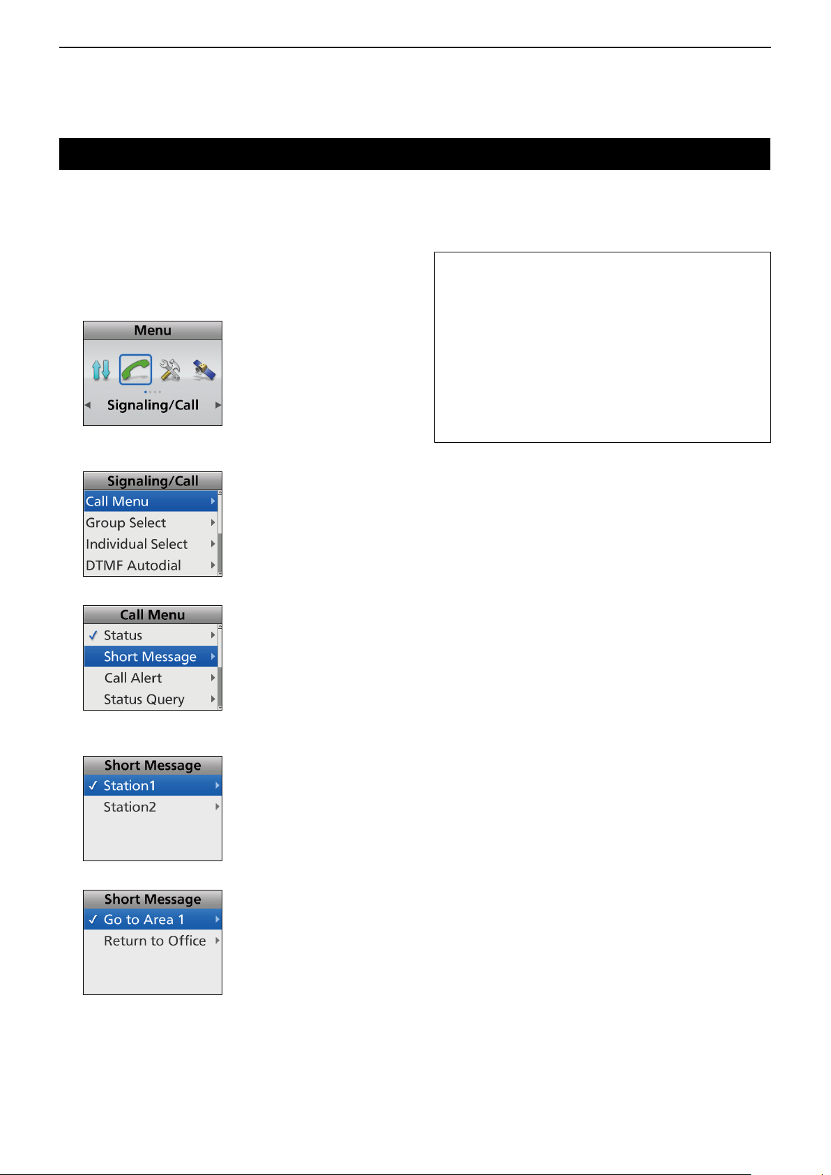
7
APCO P25 MODE OPERATION
Transmitting a call (Continued)
D Transmitting a Short Message
A user can transmit a preset message of up to 100
characters.
(Menu > Signaling/Call > Call Menu)
1. Push [Menu] to display the Menu screen.
2. Push [Left] or [Right] to select “Signaling/Call,”
then
push [OK].
3. Push [Up] or [Down] to select “Call Menu,” then
push [OK].
4. Select “Short Message,” then push [OK].
TIP:
• You can also transmit a Short Message through
“Short Message.”
(Menu > Signaling/Call > Short Message)
• Push [Call Menu] to directly display the “Call
Menu” screen in step 4 to the left.
• Push [Short Message] to directly display the “Short
Message” screen in step 5 to the left.
• Hold down [Status] for 1 second transmit the
preset Status Message to the currently selected
destination.
5. Select the target Individual station, then push
[OK].
6. Select a Message, then push [PTT] to transmit it.
• “Success” is displayed after receiving an
acknowledgment from the target station.
• “Failed” is displayed if the target station does not send
back an acknowledgment.
7-5
Page 79
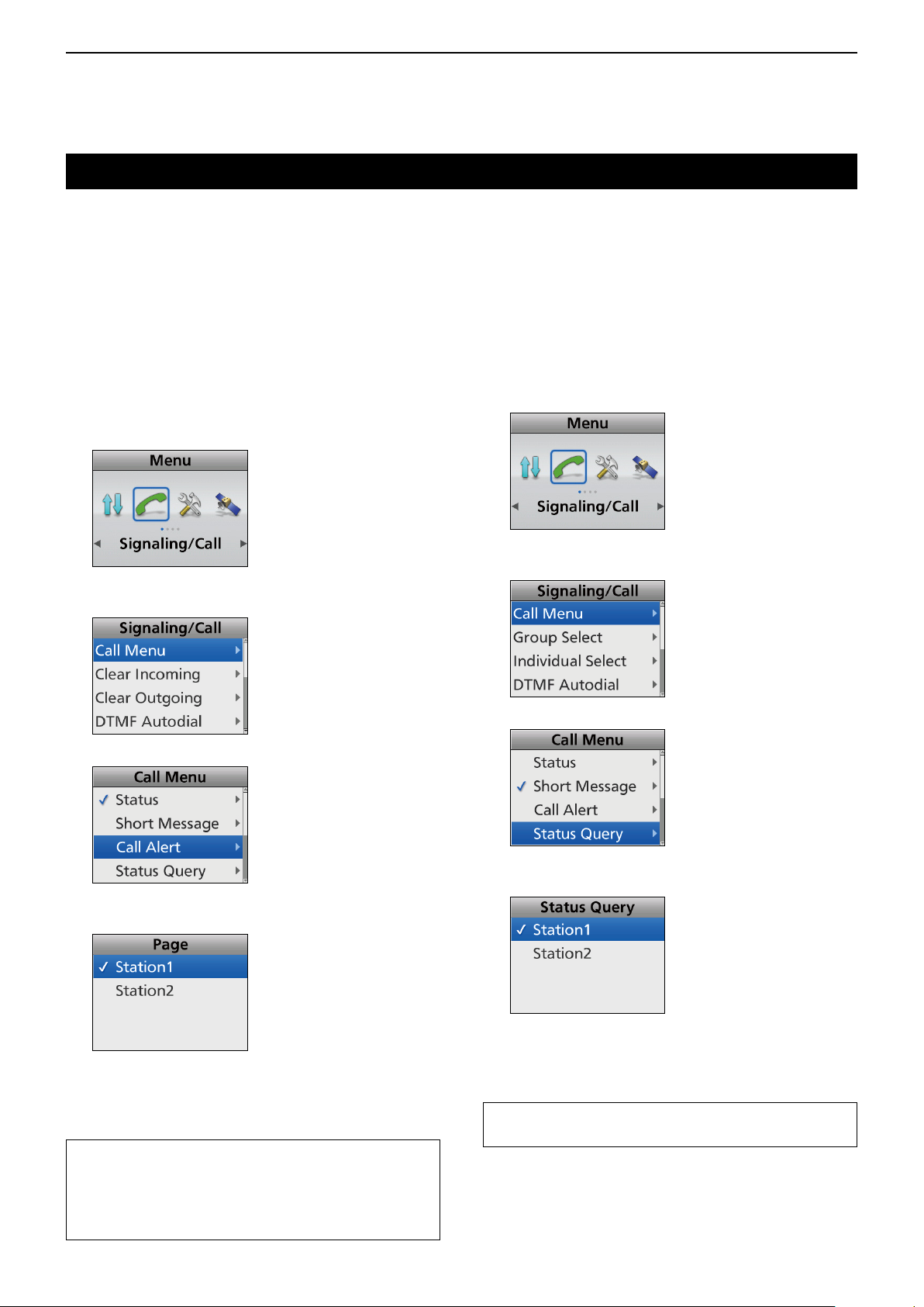
7
APCO P25 MODE OPERATION
Transmitting a call (Continued)
D Transmitting a Call Alert call
A Call Alert call is designed to notify the target station
user who may be away from his/her transceiver, or in
noisy environment with an alert and indication.
If the target station is active when a signal is received,
an acknowledgment is automatically transmitted.
The calling station can verify whether a target station
is active or not.
(Menu > Signaling/Call > Call Menu)
1. Push [Menu] to display the Menu screen.
2. Push [Left] or [Right] to select “Signaling/Call,”
then
push [OK].
3. Push [Up] or [Down] to select “Call Menu,” then
push [OK].
D Transmitting a Status Query call
A Status Query call requests the target transceiver to
transmit status messages.
When a Status Query call is received, the target
transceiver automatically transmits the last transmitted
Status message.
(Menu > Signaling/Call > Call Menu)
1. Push [Menu] to display the Menu screen.
2. Push [Left] or [Right] to select “Signaling/Call,”
then
push [OK].
3. Push [Up] or [Down] to select “Call Menu,” then
push [OK].
4. Select “Call Alert,” then
5. Select the target Individual station, then push
[PTT] to transmit a Call Alert call.
• “Success” is displayed after receiving an
acknowledgment from the target station.
• “Failed” is displayed if the target station does not send
back an acknowledgment.
TIP:
• Push [Call Menu] to directly display the “Call
Menu” screen in step 4 as described above.
• Push [Call Alert] to directly display the “Call Alert”
screen in step 5 as described above.
push [OK].
4. Select “Status Query,” then
5. Select the target Individual station, then push
[PTT] to transmit a Status Query call.
• “Status Query” and the message from the target
station are displayed.
• “Failed” is displayed if the target station does not send
back an acknowledgment.
TIP: Push [Call Menu] to directly display the “Call
Menu” screen in step 4 as described above.
push [OK].
7-6
Page 80

7
APCO P25 MODE OPERATION
Transmitting a call (Continued)
D Transmitting a Remote Monitor call
Remote Monitor call enables to send a signal that
requires the target station to transmit the microphone
audio.
(Menu > Signaling/Call > Call Menu)
1. Push [Menu] to display the Menu screen.
2. Push [Left] or [Right] to select “Signaling/Call,”
then
push [OK].
3. Push [Up] or [Down] to select “Call Menu,” then
push [OK].
D Transmitting a Radio Check call
A Radio Check call enables to determine whether the
target station is turned ON, within the communication
range and on the channel, without requiring any action
from the target station user.
(Menu > Signaling/Call > Call Menu)
1. Push [Menu] to display the Menu screen.
2. Push [Left] or [Right] to select “Signaling/Call,”
then
push [OK].
3. Push [Up] or [Down] to select “Call Menu,” then
push [OK].
4. Select “Remote Monitor,” then
5. Select the target Individual station, then push
[PTT] to transmit a Remote Monitor call.
• “Success” is displayed after receiving an
acknowledgment from the target station.
• “Failed” is displayed if the target station does not send
back an acknowledgment.
6. The microphone audio can be heard for the preset
period of time.
TIP: Push [Call Menu] to directly display the “Call
Menu” screen in step 4 above.
push [OK].
4. Select “Radio Check,” then
5. Select the target Individual station, then push
[PTT] to transmit a Radio Check call.
• “Success” is displayed after receiving an
acknowledgment from the target station.
• “Failed” is displayed if the target station does not send
back an acknowledgment.
TIP: Push [Call Menu] to directly display the “Call
Menu” screen in step 4 above.
push [OK].
7-7
Page 81
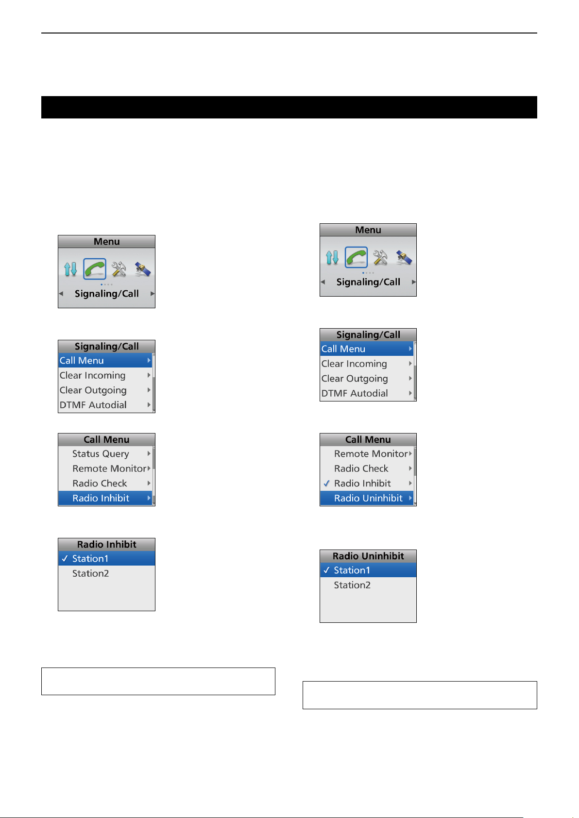
7
APCO P25 MODE OPERATION
Transmitting a call (Continued)
D Transmitting a Radio Inhibit call
A Radio Inhibit function enables to send a signal that
inhibits (stun or kill, depending on the presetting) the
target transceiver.
(Menu > Signaling/Call > Call Menu)
1. Push [Menu] to display the Menu screen.
2. Push [Left] or [Right] to select “Signaling/Call,”
then
push [OK].
3. Push [Up] or [Down] to select “Call Menu,” then
push [OK].
4. Select “Radio Inhibit,” then
push [OK].
D Transmitting a Radio Uninhibit call
A Radio Uninhibit function enables to send a signal
that revives the inhibited transceiver.
(Menu > Signaling/Call > Call Menu)
1. Push [Menu] to display the Menu screen.
2. Push [Left] or [Right] to select “Signaling/Call,”
then
push [OK].
3. Push [Up] or [Down] to select “Call Menu,” then
push [OK].
4. Push [Up] or [Down] to select “Radio Uninhibit,”
then
push [OK].
5. Select the target Individual station, then push
[PTT] to transmit a Radio Inhibit call.
• “Success” is displayed after receiving an
acknowledgment from the target station.
• “Failed” is displayed if the target station does not send
back an acknowledgment.
TIP: Push [Call Menu] to directly display the “Call
Menu” screen in step 4 above.
5. Push [Up] or [Down] to select the target Individual
station, then push [PTT] to transmit a Radio
Uninhibit call.
• “Success” is displayed after receiving an
acknowledgment from the target station.
• “Failed” is displayed if the target station does not send
back an acknowledgment.
TIP: Push [Call Menu] to directly display the “Call
Menu” screen in step 4 above.
7-8
Page 82

7
APCO P25 MODE OPERATION
Transmitting a call (Continued)
D Transmitting a Phone call
A user can make a Phone call that is similar to
standard phone calls. A transceiver and a PSTN
(Public Switched Telephone Network) can access
each other. When no phone number is preset, a
Phone call cannot be made.
(Menu > Signaling/Call > Call Menu)
1. Push [Menu] to display the Menu screen.
2. Push [Left] or [Right] to select “Signaling/Call,”
then
push [OK].
3. Push [Up] or [Down] to select “Call Menu,” then
push [OK].
D Transmitting an Emergency call
An APCO P25 mode Emergency call can be
transmitted in the same way as the 2-Tone or MDC
1200 signaling operation. See “Emergency call” for
details. (pp. 4-3 ~ 4-6)
4. Select “Phone,” then
5. Select the target telephone station, then push
[PTT] to transmit a Phone call.
• Beeps (PiPi) sound after the Phone call is connected
to the target station.
If your Phone call is not connected, push [Back] to
return to the standby mode.
6. Hold down [PTT] to speak.
7. Release [PTT] to receive.
8. After conversation is nished, push [Back] to
disconnect the Phone call.
push [OK].
TIP: Push [Call Menu] to directly display the “Call
Menu” screen in step 4 above.
7-9
Page 83

7
APCO P25 MODE OPERATION
Receiving a call
D Receiving an Individual call
1. When an Individual call is received:
• Mute is released.
• The calling station name (or ID) is displayed while
receiving the signal.*
2. Hold down [PTT] to speak.
3. Release [PTT] to receive.
D Receiving a Group call
1. When a Group call is received:
• Mute is released.
• The Group name and the calling station name (or ID)
are displayed while receiving the signal.*
When an All Call is received, “All Call” is displayed. In
that case, you cannot reply to it.
D Receiving a Short message
1. When a Short message is received:
• Beeps sound.
• The Short message and the calling station or Group
name (or ID) are displayed.
• “
” blinks.
• “
” may be displayed or blink.*
• Portable type transceivers may vibrate.*
2. Push [Back] to stop the display indication.
D Receiving a Call Alert call
1. When a Call Alert call is received:
• Beeps sound.
• “Call Alert” and the calling station name (or ID) are
displayed.*
• “
” may be displayed or blink.*
• Portable type transceivers may vibrate. *
2. Hold down [PTT] to speak.
3. Release [PTT] to receive.
D Receiving a Status message
1. When a Status message is received:
• Beeps sound.
• The Status message and the calling station name (or
ID) are displayed.*
• “
” blinks.
• “
” may be displayed or blink.*
• Portable type transceivers may vibrate.*
2. Push [Back] to stop the display indication.
The transceiver automatically transmit an
acknowledgment.
2. Push [Back] to stop the display indication.
D Receiving a Status Query call
When a Status Query call is received, the transceiver
automatically transmits the last transmitted Status
message.
D Receiving a Remote Monitor call
When a Remote monitor call is received, the
microphone audio is automatically transmitted for the
preset period of time.
D Receiving a Radio Check call
When a Radio check call is received, the transceiver
automatically transmits an acknowledgment call.
* Depending on the presetting.
7-10
Page 84

7
APCO P25 MODE OPERATION
Receiving a call (Continued)
D Receiving a Radio Inhibit call
If a Radio Inhibit is received, the transceiver will
display the preset text (example: “SORRY”) and you
cannot receive nor transmit.
When a “Decode Action” is set to “Stun”:
To use the transceiver again, do the following.
Receive an Uninhibit call.
Enter the password.
Setup again using the CS-F7500.
When a “Decode Action” is set to “Kill”:
To use the transceiver again, setup again using the
CS-F7500.
(Digital > Radio Inhibit/Uninhibit > Decode Action)
D Receiving a Phone call
1. When a Phone call is received:
• Ringers sound.
• “PHONE CALL” and “
” are displayed.
D Receiving an Emergency call
1. When an Emergency call is received:
• Beeps sound.
• The preset Emergency text (example: “Emergency”)
and the calling station name (or ID) are alternately
displayed.
2. When the Send Ack function is turned ON,
the transceiver automatically transmits an
acknowledgment to the calling station.
3. Hold down [PTT] to speak.
4. To stop the beep and display indication, do the
following.
Turn OFF the transceiver
Change the channel
Push the [Back] key
2. Hold down [PTT] to speak.
3. Release [PTT] to receive.
4. After the conversation is finished, push [Back] to
disconnect the Phone call.
7-11
Page 85

7
APCO P25 MODE OPERATION
Incoming list
The transceiver saves a log of the received Individual
calls, Call Alert calls, Status messages, and Messages
in the memory, depending on the presetting.
Up to 10 Message/Status or 5 Voice/Call Alert calls
can be saved in the log, and the oldest call record
is erased when an 11th (Message/Status) or 6th
(Voice/Call Alert) call is received. However, once the
transceiver is turned OFF, the all records are erased.
D Displaying the Incoming list
(Menu > Signaling/Call > Incoming)
1. Push [Menu] to display the Menu screen.
2. Push [Left] or [Right] to select “Signaling/Call,”
then
push [OK].
5. When “Voice/Call Alert” is selected in step 4:
The “Voice/Call Alert” screen is displayed.
3. Push [Up] or [Down] to select “Incoming,” then
push [OK].
If there is no log, an error beep sounds and the log is
not displayed.
4. Push [Up] or [Down] to select “Voice/Call Alert” or
“Message/Status,” then
• Voice/Call Alert: The received Individual call
• Message/Status: The received Status message
push [OK].
and Call Alert call logs are
saved.
and Message logs are saved.
• The calling station name (or ID) is displayed.
“
” is for the Individual calls.
“
” is for the Call Alert calls.
TIP: When the “Voice/Call Alert” screen is
displayed, skip step 6 and go to step 7.
When “Message/Status” is selected in step 4:
The “Message/Status” screen is displayed.
• The calling station name (or ID) is displayed.
“
” is for the Status message or Short Message.
6. Push [Up] or [Down] to select the log, then
[OK].
• The message content is displayed.
push
7-12
7.
Hold down [Back] for 1 second to return to the
standby screen.
Page 86

7
APCO P25 MODE OPERATION
Incoming list (Continued)
D Deleting the Incoming list
The receive call log can be deleted from the Incoming
list.
(Menu > Signaling/Call > Clear Incoming)
1. Push [Menu] to display the Menu screen.
2. Push [Left] or [Right] to select “Signaling/Call,”
then
push [OK].
3. Push [Up] or [Down] to select “Clear Incoming,”
then
push [OK].
4. Push [Up] or [Down] to select “Voice/Call Alert” or
“Message/Status” to be deleted, then
• Voice/Call Alert: The received Individual calls
and Call Alert calls are saved
in the log.
• Message/Status: The received Status messages
and Messages are saved in the
log.
5. Push [Left] or [Right] to select “OK,” then
[OK].
• The selected call log is deleted from the Incoming list.
6.
Hold down [Back] for 1 second to return to the
standby screen.
push [OK].
push
7-13
Page 87

7
APCO P25 MODE OPERATION
Displaying the Outgoing list
The transceiver saves a log of the transmitted
Individual calls, Group calls and Call Alert calls in the
memory.
Up to 5 calls can be saved in the log, and the oldest
call record is erased when a 6th call is received.
However, once the transceiver is turned OFF, the all
records are erased.
D Displaying the Outgoing list
(Menu > Signaling/Call > Outgoing)
1. Push [Menu] to display the Menu screen.
2. Push [Left] or [Right] to select “Signaling/Call,”
then
push [OK].
3. Push [Up] or [Down] to select “Outgoing,” then
push [OK].
4. The calling station name (or ID) is displayed in the
“Outgoing” screen.
D Deleting the Outgoing list
The transmit call log can be deleted from the Outgoing
list.
(Menu > Signaling/Call > Clear Outgoing)
1. Push [Menu] to display the Menu screen.
2. Push [Left] or [Right] to select “Signaling/Call,”
then
push [OK].
3. Push [Up] or [Down] to select “Clear Outgoing,”
then
push [OK].
4. Push [Left] or [Right] to select “OK,” then
[OK].
push
“ ” is for the Individual calls.
“
” is for the Call Alert calls.
5.
Hold down [Back] for 1 second to return to the
standby screen.
7-14
• The selected call log is deleted from the Outgoing list.
5.
Hold down [Back] for 1 second to return to the
standby screen.
Page 88

7
APCO P25 MODE OPERATION
Encryption function
The encryption function enables voice scrambling,
which provides private digital communication between
stations.
When a encrypted call is received, the squelch will
open only when the call contains a matching Key ID*.
If a call containing a different Key ID or Cipher Type*
is made on the same channel, the squelch will not
open, and the user will not hear the call.
* Depending on the presetting, opening the squelch may
also require that a matching RAN is included in the call.
Push [Scrambler/Encryption] to toggle the Encryption
function ON or OFF.
• “ ” is displayed when the Encryption function is ON.
When the Encryption function is ON, push [PTT] to make
an encrypted call.
7-15
Page 89

Section 8
MDC 1200 SYSTEM OPERATION
General ................................................................................... 8-2
Transmitting a call ..................................................................8-3
D Transmitting a PTT ID .....................................................8-3
D Transmitting an MDC Emergency call ............................ 8-3
D Transmitting an MDC Emergency Acknowledgment ....... 8-3
D Transmitting an MDC Status call ....................................8-3
D Transmitting an MDC Message call ................................8-4
D Transmitting an MDC Call Alert call ................................8-4
D Transmitting an MDC Radio Check call ..........................8-5
D Transmitting an MDC Stun call .......................................8-5
D Transmitting an MDC Revive call ....................................8-6
D Transmitting an MDC Selective Call (SelCall) ................ 8-6
Receiving a call ...................................................................... 8-7
D Receiving a PTTID .......................................................... 8-7
D Receiving an MDC Status call ........................................ 8-7
D Receiving an MDC Message call .................................... 8-7
D Receiving an MDC Call Alert call ....................................8-7
D Receiving an MDC Radio Check call .............................. 8-7
D Receiving an MDC Stun call or Revive call .................... 8-8
D Receiving an MDC Selective Call (SelCall) .................... 8-8
D Receiving an MDC Emergency call ................................ 8-8
Incoming Call log function ...................................................... 8-9
D Checking the Incoming call log ....................................... 8-9
D Deleting the Incoming call log ......................................... 8-9
8-1
Page 90

8
MDC 1200 SYSTEM OPERATION
General
This function is usable in only the Analog mode.
The MDC 1200 signaling system enhances your
transceiver’s capabilities. You can receive or transmit
PTT IDs, Emergency, Selective Call (SelCall), Call
Alert, Radio Check, Stun, Revive, Status, and
Message calls.
Set one of the assignable software key functions for
the MDC 1200 system operations. (pp. 2-12 ~ 2-21)
NOTE: Set the related settings using the CS-F7500
programming software when using the MDC 1200
system. See the Help le for details.
8-2
Page 91

8
MDC 1200 SYSTEM OPERATION
Transmitting a call
D Transmitting a PTT ID call
You can transmit a call with your station ID.
When another station receives a PTT ID call, your
station ID is displayed.
Push [PTT] to make a call.
• Beeps sound, depending on the presetting.
• Your station ID is transmitted when you push [PTT] (at the
beginning of the transmission) or release [PTT] (at the end
of transmission), depending on the presetting.
D Transmitting an MDC Emergency call
An MDC Emergency call can be transmitted in
the same way as the 2-Tone or APCO P25 mode
operation. See “Emergency call” for details. (pp. 4-3 ~
4-6)
The transceiver can also be set to keep the
microphone open in the Emergency mode to monitor
the situation, depending on the presetting.
D Transmitting an MDC Emergency
Acknowledgment
When receiving an MDC Emergency call, an MDC
Emergency Acknowledgment is automatically
transmitted, depending on the presetting.
D Transmitting an MDC Status call
An MDC Status call enables you to send a preset
Status call. There are 16 kinds of Status calls.
In addition, the transceiver can send an MDC Status
Poll call that make the target station to automatically
transmit a Status call, depending on the presetting.
4. Push [Up] or [Down] to select “Status,” then
[OK].
5. Select a Status call, then push [PTT] to transmit
an MDC Status call.
• “Success” is displayed after receiving an
acknowledgment from the target station.
• “Failed” is displayed if the target station does not send
back an acknowledgment.
TIP:
• You can also transmit a Status call through “Call
Menu.”
(Menu > Signaling/Call > Call Menu > Status)
• Push [Status] to directly display the “Status”
screen in step 4 above.
• Hold down [Status] for 1 second to transmit the
preset Status call that is set in the “Status” screen.
push
(Menu > Signaling/Call > Call Menu > Status)
1. Push [Menu] to display the Menu screen.
2. Push [Left] or [Right] to select “Signaling/Call,”
then
push [OK].
3. Push [Up] or [Down] to select “Call Menu,” then
push [OK].
8-3
Page 92

8
MDC 1200 SYSTEM OPERATION
Transmitting a call (Continued)
D Transmitting an MDC Message call
You can send a MDC Message call. There are 16
kinds of Messages.
(Menu > Signaling/Call > Message)
1. Push [Menu] to display the Menu screen.
2. Push [Left] or [Right] to select “Signaling/Call,”
then
push [OK].
3. Push [Up] or [Down] to select “Call Menu,” then
push [OK].
4. Push [Up] or [Down] to select “Message,” then
push [OK].
D Transmitting an MDC Call Alert call
An MDC Call Alert call enables you to notify another
user who may be away from the transceiver that you
want to talk.
It also informs a user who is away from their
transceiver, that they have received a call from
another user.
(Menu > Signaling/Call > Call Menu > Call Alert)
1. Push [Menu] to display the Menu screen.
2. Push [Left] or [Right] to select “Signaling/Call,”
then
push [OK].
3. Push [Up] or [Down] to select “Call Menu,” then
push [OK].
5. Select a Message, then push [PTT] to transmit an
MDC Message call.
• “Success” is displayed after receiving an
acknowledgment from the target station.
• “Failed” is displayed if the target station does not send
back an acknowledgment.
TIP:
• You can also transmit a Message through “Call
Menu.”
(Menu > Signaling/Call > Call Menu > Message)
• Push [Message] to directly display the “Message”
screen in step 4 above.
• Hold down [Message] for 1 second to transmit
the preset message that is set in the “Message”
screen.
4. Select “Call Alert,” then push [OK].
5. Select a station or group ID, then push [PTT] to
transmit an MDC Call Alert call.
• “Success” is displayed after receiving an
acknowledgment from the target station.
• “Failed” is displayed if the target station does not send
back an acknowledgment.
TIP: Push [Call Menu] to directly display the “Call
Menu” screen in step 4 above.
8-4
Page 93
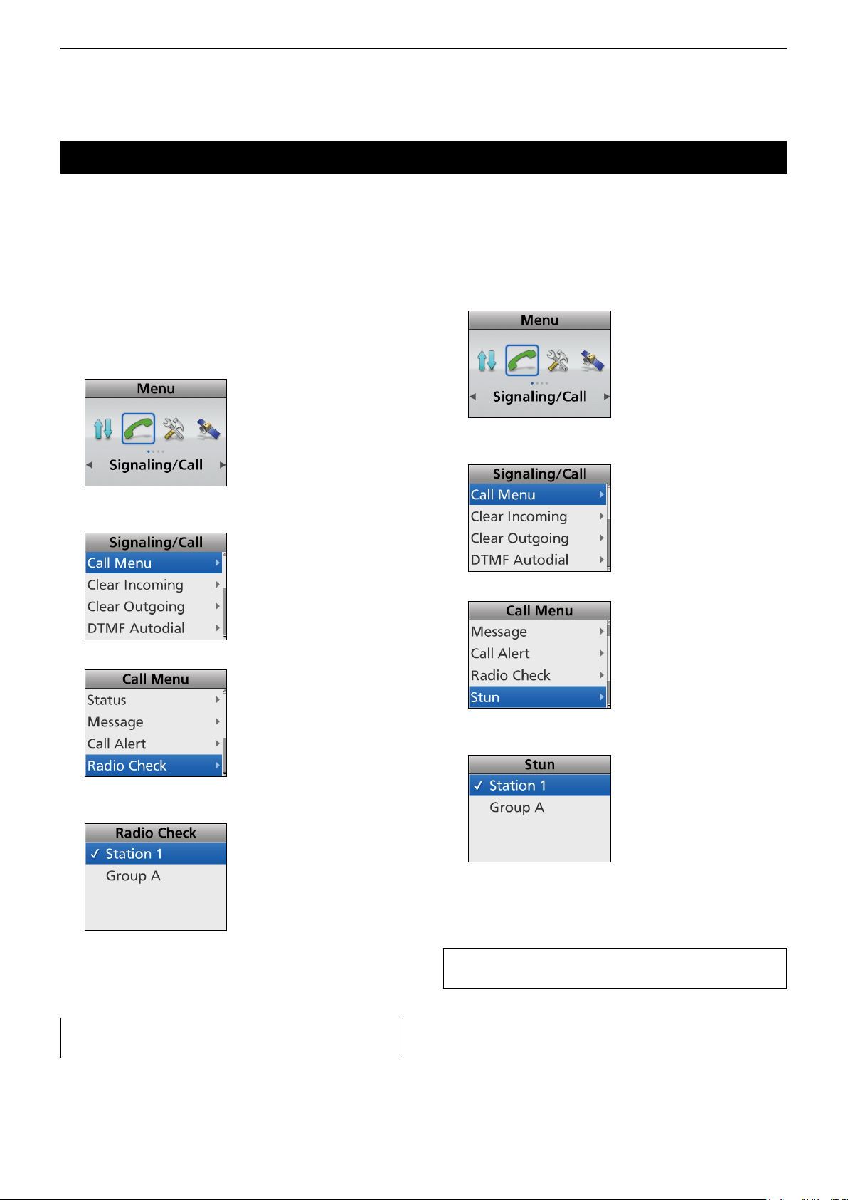
8
MDC 1200 SYSTEM OPERATION
Transmitting a call (Continued)
D Transmitting an MDC Radio Check call
An MDC Radio Check call enables the user to
determine whether the target station is turned ON,
within the communication range and on the channel,
without requiring any action from the target station
user.
(Menu > Signaling/Call > Call Menu > Radio Check)
1. Push [Menu] to display the Menu screen.
2. Push [Left] or [Right] to select “Signaling/Call,”
then
push [OK].
3. Push [Up] or [Down] to select “Call Menu,” then
push [OK].
D Transmitting an MDC Stun call
An MDC Stun call remotely disables the transceiver.
(Menu > Signaling/Call > Call Menu > Stun)
1. Push [Menu] to display the Menu screen.
2. Push [Left] or [Right] to select “Signaling/Call,”
then
push [OK].
3. Push [Up] or [Down] to select “Call Menu,” then
push [OK].
4. Select “Stun,” then push [OK].
4. Select “Radio Check,” then push [OK].
5. Select a station ID, then push [PTT] to transmit an
MDC Radio Check call.
• “Success” is displayed after receiving an
acknowledgment from the target station.
• “Failed” is displayed if the target station does not send
back an acknowledgment.
TIP: Push [Call Menu] to directly display the “Call
Menu” screen in step 4 above.
5. Select a station ID, then push [PTT] to transmit an
MDC Stun call.
• “Success” is displayed after receiving an
acknowledgment from the target station.
• “Failed” is displayed if the target station does not send
back an acknowledgment.
TIP: Push [Call Menu] to directly display the “Call
Menu” screen that is described in step 4 above.
8-5
Page 94
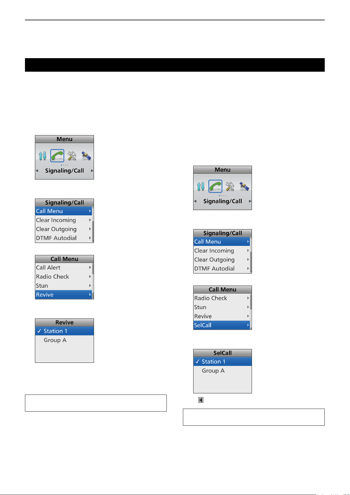
8
MDC 1200 SYSTEM OPERATION
Transmitting a call (Continued)
D Transmitting an MDC Revive call
An MDC Revive call revives a stunned transceiver to
normal operation.
(Menu > Signaling/Call > Call Menu > Revive)
1. Push [Menu] to display the Menu screen.
2. Push [Left] or [Right] to select “Signaling/Call,”
then
push [OK].
3. Push [Up] or [Down] to select “Call Menu,” then
push [OK].
4. Select “Revive,” then push [OK].
D Transmitting an MDC Selective Call
(SelCall)
An MDC SelCall enables you to make a call to a
speci c station, or to a particular group. Other MDC
1200 system transceivers on the channel do not
receive a SelCall that does not include the matching
station or group ID.
(Menu > Signaling/Call > Call Menu > SelCall)
1. Push [Menu] to display the Menu screen.
2. Push [Left] or [Right] to select “Signaling/Call,”
then
push [OK].
3. Push [Up] or [Down] to select “Call Menu,” then
push [OK].
5. Select a station ID, then push [PTT] to transmit an
MDC Revive call.
• “Success” is displayed after receiving an
acknowledgment from the target station.
• “Failed” is displayed if the target station does not send
back an acknowledgment.
TIP: Push [Call Menu] to directly display the “Call
Menu” screen in step 4 above.
4. Select “SelCall.”
5. Select a station or group ID, then push [PTT] to
transmit an MDC SelCall.
• “ ” is displayed while transmitting the SelCall.
TIP: Push [Call Menu] to directly display the “Call
Menu” screen in step 4 above.
8-6
Page 95
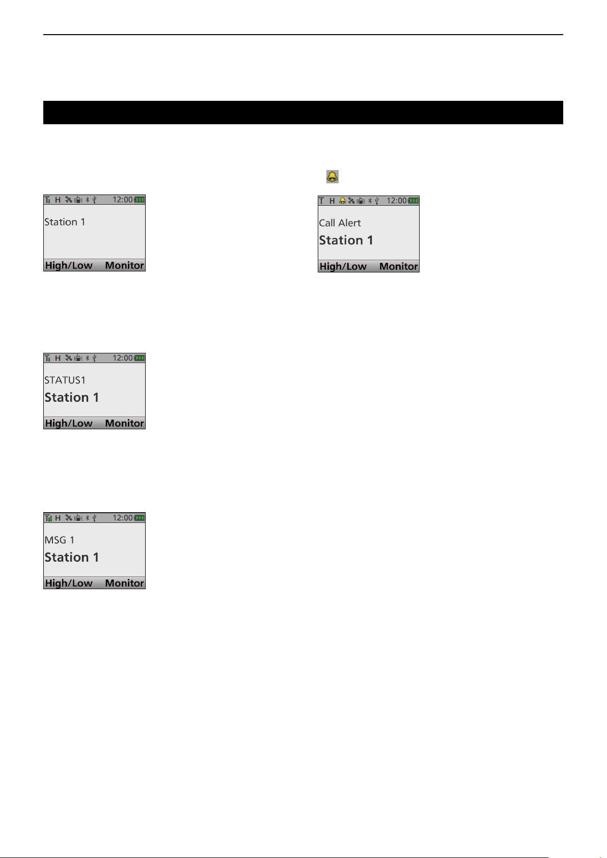
8
MDC 1200 SYSTEM OPERATION
Receiving a call
D Receiving a PTT ID call
When a PTT ID call is received:
• Beeps sound.*
• Portable type transceivers may vibrate.*
• The calling station's name (or ID) is displayed.
D Receiving an MDC Status call
When an MDC Status call is received.
• Beeps sound.
• The calling station's name (or ID) and the Status message
are displayed for preset period of time.
D Receiving an MDC Call Alert call
When an MDC Call Alert call is received:
• Beeps sound.
• “
” blinks.
• The calling station's ID is displayed.
To return to the Standby screen, push [Back].
D Receiving an MDC Radio Check call
When a Radio check call is received, the transceiver
automatically transmits an acknowledgment call.
D Receiving an MDC Message call
When an MDC Message call is received.
• Beeps sound.
• The calling station's name (or ID) and the message are
displayed.
To return to the Standby screen, push [Back].
* Depending on the presetting.
8-7
Page 96

8
MDC 1200 SYSTEM OPERATION
Receiving a call (Continued)
D Receiving an MDC Stun call or Revive
call
If an MDC Stun call is received that matches your
station ID, the transceiver will display the preset text
(example:
transmit.
To use the transceiver again, do the following.
Receive an MDC Revive call that matches your
station ID.
Enter the password.
Setup again using the CS-F7500.
“SORRY”) and you cannot receive nor
D Receiving an MDC Selective Call (SelCall)
When an MDC SelCall is received:
• Beeps sound.
• “
” is displayed.
• “
” blinks.
• The calling station's ID is displayed.
D Receiving an MDC Emergency call
When an MDC Emergency call is received:
• Beeps sound.
• Portable type transceivers may vibrate.*
• The calling station's ID and “Emergency” is displayed.
The transceiver automatically may transmit an
acknowledgment to the calling station, depending
on the setting.
1. Hold down [PTT] to speak.
2. To stop the beep and display indication, do the
following.
Turn OFF the transceiver
Change the channel
Push a key
Hold down [PTT] to speak.
* Depending on the presetting.
8-8
Page 97

8
MDC 1200 SYSTEM OPERATION
Incoming Call log function
After receiving an MDC SelCall, Call Alert call, or
Emergency call, the call log may be displayed,
depending on the presetting. Up to 5 calls can be
memorized, and the oldest call is deleted when a 6th
call is received.
D Checking the Incoming call log
(Menu > Signaling/Call > Incoming)
1. Push [Menu] to display the Menu screen.
2. Push [Left] or [Right] to select “Signaling/Call,”
then
push [OK].
3. Push [Up] or [Down] to select “Incoming,” then
push [OK].
If there is no log, an error beep sounds and the log is
not displayed.
D Deleting the Incoming call list
The receive call log can be deleted from the Incoming
list.
(Menu > Signaling/Call > Clear Incoming)
1. Push [Menu] to display the Menu screen.
2. Push [Left] or [Right] to select “Signaling/Call,”
then
push [OK].
3. Push [Up] or [Down] to select “Clear Incoming,”
then
push [OK].
“ ” is for the Emergency calls.
“
” is for the SelCalls.
“
” is for the Call Alert calls.
4.
Hold down [Back] for 1 second to return to the
standby screen.
4. Push [Left] or [Right] to select <OK>, then
[OK].
• The selected call log is deleted from the Incoming list.
5.
Hold down [Back] for 1 second to return to the
standby screen.
8-9
push
Page 98

Section 9
ABOUT THE microSD CARD
About the microSD card ......................................................... 9-2
Saving data onto the microSD card ........................................ 9-2
Inserting or removing the microSD card ................................. 9-3
D Inserting .......................................................................... 9-3
D Removing ........................................................................ 9-3
Unmounting the microSD card ............................................... 9-4
Formatting the microSD card.................................................. 9-4
Loading the saved data les onto a microSD card ................. 9-5
Displaying the information of the microSD card ..................... 9-6
Backing up the data saved on the microSD card onto a PC .. 9-7
D About the microSD card’s folder contents....................... 9-7
D Making a backup le on your PC .................................... 9-8
9-1
Page 99

9
ABOUT THE microSD CARD
About the microSD card
The microSD or microSDHC card is not supplied by Icom.
User supplied.
Users can use a microSDHC of up to 32 GB.
Icom has checked the compatibility with the following
microSDHC cards.
(As of August 2017)
Brand Type Memory size
4 GB
SanDisk
L The above list does not guarantee the card’s
performance.
L Through the rest of this document, the microSDHC
card is simply called the microSD card or the card.
TIP: Icom recommends that a user save the
transceiver’s factory default data for backup. (p. 9-7)
NOTE:
• Before using the microSD card, thoroughly read the
card’s instructions.
• If you do any of the following, the card data may be
corrupted or deleted.
- You remove the card from the transceiver while
the card is being accessed.
- A power failure occurs, or the power cable
(Mobile type) or battery pack (Portable type) is
disconnected while the card is being accessed.
- You drop, impact or vibrate the card.
• Do not touch the contacts of the card.
• The transceiver takes a longer time to recognize a
high capacity card.
• The card will get warm if continuously used for a
long period of time.
• The card has a certain lifetime, so data reading or
writing may not be possible after using it for a long
period of time.
When reading or writing data is impossible, the
card’s lifetime has ended. In that case, use a new
one.
We recommend you make a separate backup le of
the important data onto your PC. (p. 9-7)
• Icom will not be responsible for any damage
caused by data corruption on a card.
®
microSDHC
8 GB
16 GB
32 GB
Saving data onto the microSD card
A user can save the following data onto the microSD
card:
• Communication audio
The transmitted and received audio.
• Data settings of the transceiver
Memory channel contents saved in the optional
programming software.
• Firmware les
The rmware les to update the transceiver’s
rmware.
• Voice audio of an Emergency
• GPS log
9-2
Page 100

9
ABOUT THE microSD CARD
Inserting or removing the microSD card
NOTE: Use the transceiver's built-in Format function
to format all microSD cards to be used with the
transceiver. Format, even preformatted cards for
PCs or other uses. (p. 9-4)
D Inserting
z Portable types
Insert the card into the slot until it locks in place, until
it makes a ‘click’ sound.
• The SD card icon is displayed when the microSD card is
inserted.
LBe sure to check the card orientation.
microSD
card
SD
micro
Transceiver
z Mobile types
1. Turn OFF the transceiver.
2. Turn the transceiver upside down.
3. Push the locking tab using a solid tool, such as a
flat-bladed screwdriver (q), then detach the front
panel (w).
Card orientation
q
q
w
Front panel
Rear
Bottom
Front
Top
D Removing
z Portable types
Push in the microSD card until a click sounds.
• The card is unlocked, and you can pull it out.
L Before you remove the microSD card while the
transceiver’s power is ON, be sure to rst unmount it.
(p. 9-4)
microSD card
Transceiver
z Mobile types
1. Detach the front panel, as described to the left.
2. Push in the microSD card until it makes a click
sound.
• The card is unlocked, and you can pull it out.
L Before you remove the microSD card while the
transceiver’s power is ON, be sure to rst unmount it.
(p. 9-4)
4. Turn the transceiver right-side up.
5. Insert the card into the slot until it locks in place,
and makes a ‘click’ sound.
• The SD card icon is displayed when the microSD card
is inserted.
LBe sure to check the card orientation.
microSD
microSD
card
card
Transceiver
Card orientation
Rear
SD
micro
Top
Bottom
Front
6. Attach the front panel, then turn ON the transceiver.
Top
Rear
Front
Bottom
Transceiver
9-3
 Loading...