

Page 1
Battery pack Belt clip Connector cover
(with a screw)
z
x
z
INSTRUCTIONS
VHF P25 TRANSCEIVERS
iF7010T/iF7010S
UHF P25 TRANSCEIVERS
iF7020T/iF7020S
iF7040T/iF7040S
Thank you for choosing this Icom product.
READ ALL INSTRUCTIONS carefully and completely
before using this product.
IMPORTANT
This instruction sheet includes some functions that are
usable only when they are preset by your dealer. The
transceiver may have other functions and operations that
are not described in this instruction sheet. Ask your dealer
for preset function details.
EXPLICIT DEFINITIONS
WORD DEFINITION
R DANGER! Personal death, serious injury or an
R WARNING! Personal injury, fi re hazard or electric
CAUTION Equipment damage may occur.
NOTE If disregarded, inconvenience only. No
Icom is not responsible for the destruction, damage to, or
performance of any Icom or non-Icom equipment, if the
malfunction is because of:
• Force majeure, including, but not limited to, fi res,
earthquakes, storms, fl oods, lightning, other natural
disasters, disturbances, riots, war, or radioactive
contamination.
• The use of Icom transceivers with any equipment that
is not manufactured or approved by Icom.
Icom, Icom Inc. and the Icom logo are registered
trademarks of Icom Incorporated (Japan) in Japan, the
United States, the United Kingdom, Germany, France,
Spain, Russia, Australia, New Zealand, and/or other
countries.
AMBE+2 is a trademark and property of Digital Voice
Systems Inc.
All other products or brands are registered trademarks or
trademarks of their respective holders.
1-1-32 Kamiminami, Hirano-ku,
Osaka 547-0003, Japan
explosion may occur.
shock may occur.
risk of personal injury, fi re or electric
shock.
A7377H-1EX-2
Printed in Japan
© 2017–2018 Icom Inc.
FCC INFORMATION
This equipment has been tested and found to comply with
the limits for a Class A digital device, pursuant to part 15
of the FCC Rules. These limits are designed to provide
reasonable protection against harmful interference when
the equipment is operated in a commercial environment.
This equipment generates, uses, and can radiate
radio frequency energy and, if not installed and used
in accordance with the instruction manual, may cause
harmful interference to radio communications. Operation
of this equipment in a residential area is likely to cause
harmful interference in which case the user will be
required to correct the interference at his own expense.
CAUTION: Changes or modifications to this transceiver,
not expressly approved by Icom Inc., could void
your authority to operate this transceiver under FCC
regulations.
This device complies with Part 15 of the FCC Rules.
Operation is subject to the condition that this device does
not cause harmful interference.
PRECAUTIONS
R DANGER! NEVER short the terminals of the battery
pack.
Shorting may occur if the terminals touch metal objects
such as a key, so be careful when placing the battery
packs (or the transceiver) in bags, and so on. Carry them
so that shorting cannot occur with metal objects. Shorting
may damage not only the battery pack, but also the
transceiver.
R DANGER! NEVER use or charge Icom battery packs
with non-Icom transceivers or non-Icom chargers. Only
Icom battery packs are tested and approved for use with
Icom transceivers or charged with Icom chargers. Using
third-party or counterfeit battery packs or chargers may
cause smoke, fi re, or cause the battery to burst.
R DANGER! NEVER operate the transceiver near
unshielded electrical blasting caps or in an explosive
atmosphere.
R WARNING! NEVER hold the transceiver so that the
antenna is very close to, or touching exposed parts of the
body, especially the face or eyes, while transmitting. The
transceiver will perform best if the microphone is 5 to 10
cm (2 to 4 inches) away from the lips and the transceiver
is vertical.
R WARNING! NEVER operate the transceiver with a
headset or other audio accessories at high volume levels.
The continuous high volume operation may cause a
ringing in your ears. If you experience the ringing, reduce
the volume level or discontinue use.
CAUTION: DO NOT use harsh solvents such as Benzine
or alcohol when cleaning. This could damage the
equipment surfaces. If the surface becomes dusty or dirty,
wipe it clean with a soft, dry cloth.
CAUTION: DO NOT place or leave the transceiver in
excessively dusty environments. This could damage the
transceiver.
CAUTION: DO NOT expose the transceiver to rain, snow
or any liquids. The transceiver meets IP68 requirements
for dustprotection and splash resistance. However, once
the transceiver has been dropped, dust protection and
splash resistance cannot be guaranteed due to the fact
that the transceiver may be cracked, or the waterproof
seal damaged, and so on.
DO NOT place or leave the transceiver in direct sunlight or
in areas outside of the specifi ed temperature range:
–30°C (–22°F) ~ +60°C (+140°F)
Keep the transceiver in a secure place to prevent use by
unauthorized persons.
D Battery caution
Misuse of Li-ion batteries may result in the following
hazards: smoke, fi re, or the battery may rupture. Misuse
can also cause damage to the battery or degradation of
battery performance.
R DANGER! NEVER solder the battery terminals, or
NEVER modify the battery pack. This may cause heat
generation, and the battery may burst, emit smoke or
catch fi re.
R DANGER! NEVER place or leave battery packs in
areas with temperatures above 60°C (140°F). High
temperature buildup in the battery cells, such as could
occur near fi res or stoves, inside a sun-heated vehicle,
or in direct sunlight for long periods of time may cause
the battery cells to rupture or catch fi re. Excessive
temperatures may also degrade the battery pack’s
performance or shorten the battery cell’s life.
R DANGER! NEVER strike or otherwise impact the
battery pack. Do not use the battery pack if it has been
severely impacted or dropped, or if the pack has been
subjected to heavy pressure. Battery pack damage may
not be visible on the outside of the case. Even if the
surface of the battery does not show cracks or any other
damage, the cells inside the battery may rupture or catch
fi re.
R DANGER! NEVER expose the battery pack to rain,
snow, seawater, or any other liquids. Do not charge or
use a wet pack. If the pack gets wet, be sure to wipe it dry
before using.
R DANGER! NEVER place or leave battery packs near
fi re.
Fire or heat may cause them to rupture or explode.
Dispose of used battery packs in accordance with local
regulations.
R DANGER! NEVER let fl uid from inside the battery get
in your eyes. This can cause blindness. Rinse your eyes
with clean water, without rubbing them, and immediately
go to a doctor.
R WARNING! NEVER put the battery pack in a microwave
oven, high-pressure container, or in an induction heating
cooker. This could cause a fi re, overheating, or cause the
battery cells to rupture.
R WARNING! NEVER use the battery pack if it emits an
abnormal odor, heats up, or is discolored or deformed. If
any of these conditions occur, contact your Icom dealer or
distributor.
R WARNING! NEVER Iet fl uid from inside the battery cells
come in contact with your body. If it does, immediately
wash with clean water.
CAUTION: DO NOT use the battery pack out of the
specifi ed temperature range for the transceiver (–30°C
~ +60°C (–22°F ~ +140°F)) and the battery itself (–20°C
~ +60°C (–4°F ~ +140°F)). Using the battery out of its
specifi ed temperature range will reduce its performance
and battery cell’s life. Please note that the specifi ed
temperature range of the battery may exceed that of the
transceiver. In such cases, the transceiver may not work
properly because it is out of its operating temperature
range.
CAUTION: DO NOT leave the pack fully charged,
completely discharged, or in an excessive temperature
environment (above 50°C, 122°F) for an extended
period of time. If the battery pack must be left unused
for a long time, it must be detached from the transceiver
after discharging. You may use the battery pack until the
remaining capacity is about half, then keep it safely in a
cool and dry place at the following temperature range:
–20°C ~ +50°C (–4°F ~ +122°F) (within a month)
–20°C ~ +40°C (–4°F ~ +104°F) (within three months)
–20°C ~ +20°C (–4°F ~ +68°F) (within a year)
BE SURE to replace the battery pack with a new one
approximately fi ve years after manufacturing, even if it still
holds a charge. The material inside the battery cells will
become weak after a period of time, even with little use.
The estimated number of times you can charge the pack
is between 300 and 500. Even when the pack appears to
be fully charged, the operating time of the transceiver may
become short when:
• Approximately 5 years have passed since the pack was
manufactured.
• The pack has been repeatedly charged.
D Charging caution
R DANGER! NEVER charge the battery pack in areas
with extremely high temperatures, such as near fi res or
stoves, inside a sun-heated vehicle, or in direct sunlight.
In such environments, the safety/protection circuit in the
battery will activate, causing the battery to stop charging.
R WARNING! NEVER charge the transceiver during a
lightning storm. It may result in an electric shock, cause
a fi re or damage the transceiver. Always disconnect the
power adapter before a storm.
R WARNING! NEVER charge or leave the battery in the
battery charger beyond the specifi ed time for charging. If
the battery is not completely charged by the specifi ed time,
stop charging and remove the battery from the battery
charger.
Continuing to charge the battery beyond the specifi ed time
limit may cause a fi re, overheating, or the battery may
rupture.
R WARNING! NEVER insert the transceiver (battery
attached to the transceiver) into the charger if it is wet or
soiled. This could corrode the battery charger terminals or
damage the charger. The charger is not waterproof.
CAUTION: DO NOT charge the battery outside of the
specifi ed temperature range:
BC-214: (16˚C ~ 40˚C (60.8˚F ~ 104˚F))
BC-219N: (16˚C ~ 40˚C (60.8˚F ~ 104˚F))
Otherwise, the charging time will be longer, but the battery
will not reach a full charge. While charging, at a point
after the temperature goes out of the specifi ed range, the
charging will automatically stop.
SAFETY TRAINING INFORMATION
Your Icom radio generates RF electromagnetic
energy while transmitting. This radio is designed
for and classifi ed as for “Occupational Use Only.”
This means it must be used only during the
course of employment by individuals aware of
the hazards, and the ways to minimize such hazards. This
radio is NOT intended for use by the “General Population”
in an uncontrolled environment. This radio has been tested
and complies with the FCC and IC RF exposure limits for
“Occupational Use Only”. In addition, your Icom radio
complies with the following Standards and Guidelines with
regard to RF energy and electromagnetic energy levels
and evaluation of such levels for exposure to humans:
• FCC KDB Publication 447498 D03, Evaluating
Compliance with FCC Guidelines for Human Exposure
to Radio Frequency Electromagnetic Fields.
• American National Standards Institute (C95.1-1992),
IEEE Standard for Safety Levels with Respect to
Human Exposure to Radio Frequency Electromagnetic
Fields, 3 kHz to 300 GHz.
• American National Standards Institute (C95.3-1992),
IEEE Recommended Practice for the Measurement of
Potentially Hazardous Electromagnetic Fields– RF and
Microwave.
• The antennas, batteries, belt clips, speaker-microphone,
and other accessories that are listed in “OPTIONS”
on the INSTRUCTIONS sheet, are authorized for use
with this product. Use of accessories other than those
specifi ed may result in RF exposure levels exceeding
the FCC and IC requirements for wireless RF exposure.
• Health Canada Safety Code 6 - Limits of Human
Exposure to Electromagnetic Energy in the Frequency
Range from 3 kHz to 300 GHz.
To ensure that your expose to RF
electromagnetic energy is within the FCC and IC
allowable limits for occupational use, always
adhere to the following guidelines:
DO NOT operate the radio without a proper antenna
attached, as this may damage the radio and may also
cause you to exceed FCC and IC RF exposure limits. A
proper antenna is the antenna supplied with this radio by
the manufacturer or an antenna specifi cally authorized by
the manufacturer for use with this radio.
DO NOT transmit for more than 50% of the total radio use
time (“50% duty cycle”). Transmitting more than 50% of
the time can cause FCC and IC RF exposure compliance
requirements to be exceeded. The radio is transmitting
when the LED indicator lights red. You can cause the radio
to transmit by pushing the “PTT” switch.
ALWAYS keep the antenna at least 2.5 cm (1 inch) away
from the body when transmitting, and only use the Icom
belt-clips listed in “OPTIONS” of the INSTRUCTIONS
sheet when attaching the radio to your belt, or other
place, to ensure FCC and IC RF exposure compliance
requirements are not exceeded.
The information listed above provides the user with
the information needed to make him or her aware of
RF exposure, and what to do to assure that this radio
operates within the FCC and IC RF exposure limits of this
radio.
Electromagnetic Interference/Compatibility
During transmissions, your Icom radio generates RF
energy that can possibly cause interference with other
devices or systems. To avoid such interference, turn off
the radio in areas where signs are posted to do so. DO
NOT operate the transmitter in areas that are sensitive to
electromagnetic radiation such as hospitals, aircraft, and
blasting sites.
Occupational/Controlled Use
The radio transmitter is used in situations in which persons
are exposed as a consequence of their employment,
provided those persons are fully aware of the potential for
exposure and can exercise control over their exposure.
RECOMMENDATION
CLEAN THE TRANSCEIVER THOROUGHLY IN A BOWL
OF FRESH WATER after exposure to saltwater, and dry
it before operating. Otherwise, the transceiver’s keys,
switches, and controllers may become unusable, due to
salt crystallization, and/or the charging terminals of the
battery pack may corrode.
NOTE: If the transceiver’s waterproof protection appears
defective, carefully clean the transceiver with a soft,
damp (fresh water) cloth, then dry it before operating. The
transceiver may lose its waterproof protection if the case,
jack cap, or connector cover is cracked or broken, or the
transceiver has been dropped.
Contact your Icom distributor or your dealer for advice.
VOICE CODING TECHNOLOGY
The AMBE+2™ voice coding Technology embodied in this
product is protected by intellectual property rights including
patent rights, copyrights and trade secrets of Digital Voice
Systems, Inc. This voice coding Technology is licensed
solely for use within this Communications Equipment.
The user of this Technology is explicitly prohibited from
attempting to extract, remove, decompile, reverse
engineer, or disassemble the Object Code, or in any other
way convert the Object Code into a human-readable form.
U.S. Patent Nos.
#8,595,002, #8,359,197, #8,315,860, #8,200,497,
#7,970,606, #6,912,495 B2.
ABOUT GPS/GLONASS RECEIVER
An internal GPS or GLONASS receiver may not work if the
transceiver transmits or receives in the frequency ranges
as shown below. This problem is made in the internal
circuit and does not indicate a transceiver malfunction.
For the IC-F7010T/IC-F7010S (Unit: MHz)
Transmit 142.850 ~ 142.860 145.275 ~ 145.945
Receive 146.845 ~ 147.110 149.745 ~ 150.790
For the IC-F7020T/IC-F7020S (Unit: MHz)
Transmit 392.840 ~ 392.865 399.515 ~ 401.343
Receive 443.545 ~ 444.065 449.335 ~ 451.425
For the IC-F7040T/IC-F7040S (Unit: MHz)
Transmit 799.0375 ~ 802.6875
Receive 856.1815 ~ 859.8375
GPS receiver GLONASS receiver
157.135 ~ 157.145 159.805 ~ 160.540
GPS receiver GLONASS receiver
GLONASS receiver
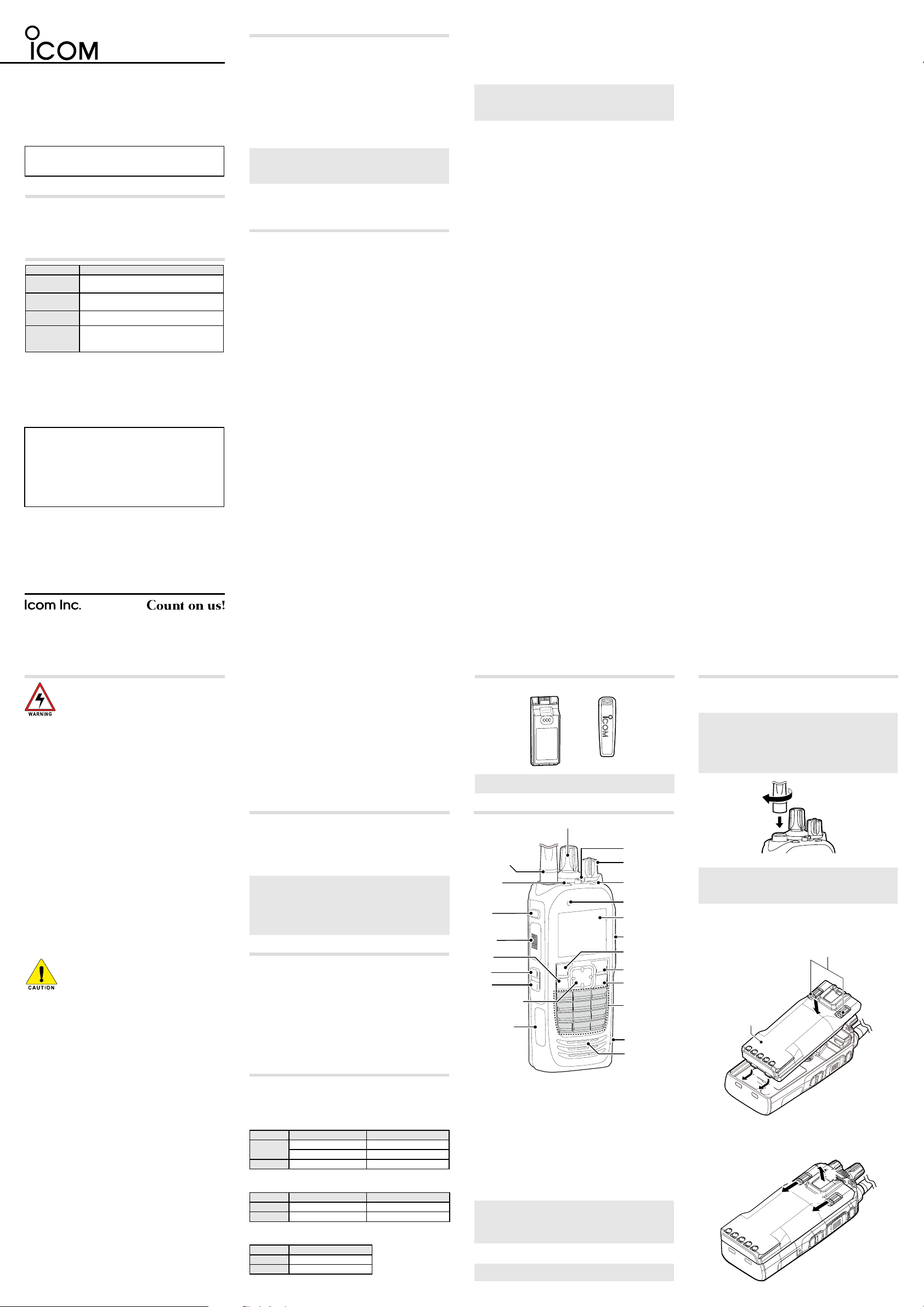
SUPPLIED ACCESSORIES
NOTE: Some accessories are not supplied, or the shape
is different, depending on the transceiver version.
PANEL DESCRIPTION
[Selector]
Antenna
Connector
[Emer]
[F1]
[PTT]
[OK]
[F2]
[F3]
[Up]/[Down]
[Right]/[Left]
USB
(Micro-B)
Connector
D About the transceiver types
There are 2 types of transceivers.
IC-F7010S/IC-F7020S/IC-F7040S: Simple key types
IC-F7010T/IC-F7020T/IC-F7040T: Ten-key types
D About the Status indicator
• Lights blue, then blinks red, yellow, and green when
turning ON the transceiver.
• Lights red while transmitting.
• Lights green while receiving a signal, or when the
squelch is open.
• Blinks magenta when the battery is exhausted.
D About the Multi-connector
Connects to an optional speaker microphone or headset.
CAUTION: DO NOT use the transceiver without the
connector cover or the optional equipment attached.
The transceiver meets IP68 requirements for dust-tight
and waterproof protection only when the connector cover
or the optional HM-222 is attached.
D About the Software key functions
NOTE: Your dealers can assign the Software key
functions to the keys, keypads, and the Lever switch.
Lever Switch
[VOL]
Status
indicator
Microphone
Function
Display
Multiconnector
[P1]
[P2]
[Back]
Ten-Key Pad
microSD
Card Slot
Speaker
ATTACHING ACCESSORIES
D Flexible antenna
Connect the antenna to the antenna connector.
CAUTION:
• DO NOT carry the transceiver by holding only the
antenna.
• DO NOT connect an antenna other than those listed in
the INSTRUCTIONS.
• Transmitting without an antenna may damage the
transceiver.
D Battery pack
CAUTION: DO NOT attach or detach the battery pack
when the transceiver is wet or soiled. This may result in
water or dust getting into the transceiver/battery pack and
may damage the transceiver.
To attach:
1. Slide the battery pack in the direction of the arrow. (1)
2. Push the battery pack until the battery sliding locks
make a ‘click’ sound. (2)
Battery sliding locks
w
Battery pack
q
q
To detach:
1. Push both battery sliding locks in the direction of the
arrow. (z)
2. Lift up to detach the battery pack. (x)
Page 2
ATTACHING ACCESSORIES (Continued)
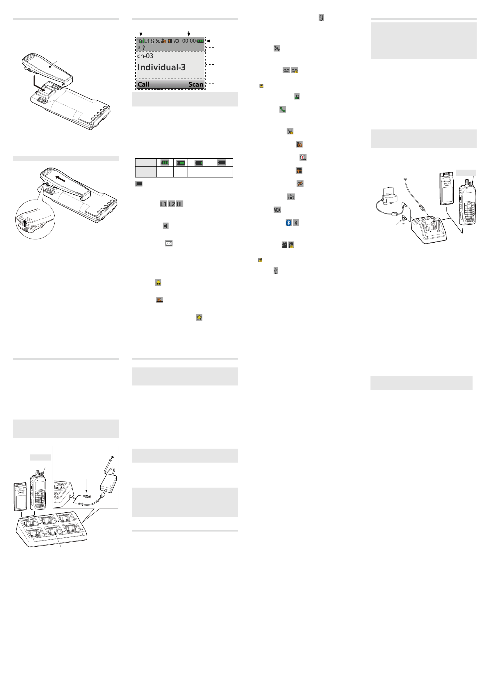
D Belt clip
To attach:
1. Remove the battery pack from the transceiver, if it is
attached.
2. Slide the belt clip in the direction of the arrow until the
belt clip is locked and makes a ‘click’ sound.
Belt clip
To detach:
Lift the tab up (1), and slide the belt clip in the direction of
the arrow (2).
BE CAREFUL! DO NOT break your fi ngernail
w
q
FUNCTION DISPLAY
1
NOTE: The screen capture is an example.
The displayed position of each icon may differ, depending
on the function being used.
D Icon Area
Indicators
1 SIGNAL STRENGTH INDICATOR
Displays the relative receive signal strength level.
2 CLOCK
Displays the current time.
“AM” or “PM” is displayed beside the time display
when 12 hour display format is selected.
3 BATTERY INDICATOR
Displayed or blinks to indicate the battery status.
Indication
Battery
Status
blinks when the battery is exhausted.
Icons
The following icons are displayed in the Icon Area.
POWER ICON
• “L1” is displayed when the output power is set to Low.
• “L2” is displayed when the output power is set to Mid.
• “H” is displayed when the output power is set to High.
AUDIBLE ICON
Displayed when the channel is in the ‘audible’ (unmute)
mode.
MESSAGE ICON
• Blinks after messages (Message or Status Message)
have been received.
• Stops blinking when the screen is changed, or any key
is pushed, but is displayed if unread messages are still
in the Message memory.
• Disappears when all messages in the Message memory
have been read.
BELL ICON
Displayed when a matching signal is received, depending
on the presetting.
SCAN ICON
• Displayed when a scan is paused.
• Blinks while scanning.
SCAN TARGET CHANNEL ICON
Displayed when a matching signal is received, depending
on the presetting.
Full Mid Charging
2
required
3
Icon Area
Text Area
Key Display
Area
Battery
exhausted
SCRAMBLER/ENCRYPTION ICON
In the Analog mode:
Displayed when the Voice Scrambler function is ON.
In the Digital mode:
• Displayed when the Voice Encryption function is ON.
• Blinks when decoding an encrypted signal.
GPS ICON
• Displayed when valid position data is received.
• Blinks when searching for satellites or calculating
position data.
RECORD ICON
• Displayed when the Record function is ON.
• Blinks while recording audio.
“
” is displayed when there is no microSD card free
space and audio cannot be recorded.
TALK AROUND ICON
Displayed when the Talk Around function is ON.
PHONE ICON
• Displayed when the transceiver is connected to a
telephone network on the selected channel.
• Blinks while receiving a phone call.
SITE LOCK ICON
Displayed when the Site Lock function is ON.
LONE WORKER ICON
Displayed when the Lone Worker function is ON.
MOTION SENSOR ICON
Displayed when the Motion Sensor function is ON.
NOISE CANCEL ICON
Displayed when the Noise Cancel function is ON.
SURVEILLANCE ICON
Displayed when the Surveillance function is ON.
VIBRATION ICON
Displayed when the Vibration function is ON.
VOX ICON
Displayed when the VOX function is ON.
®
Bluetooth
• Displayed when Bluetooth® is activated.
• Lights Blue when a Bluetooth
• Does not light when no Bluetooth
microSD ICON
Displayed when a microSD card is inserted into the card
slot.
• “
USB ICON
Displayed when a USB device is connected.
Displays the selected Zone number, Channel number, and
Channel name, if set.
Displays the names of the function assigned to
[P1] and [P2].
Ask your dealer about the assigned Software key
functions.
ICON
” is displayed when the microSD card has not been
formatted.
D Text Area
D Key Display Area
®
device is connected.
®
device is connected.
BATTERY CHARGING
NOTE:
• Before detaching or attaching a battery pack, BE
SURE to turn OFF the transceiver by rotating [VOL]
fully counter clockwise, until it makes a “click” sound.
Otherwise, a transceiver malfunction could occur.
• The internal clock will be reset to 00:00 if an exhausted
battery is left in the transceiver, or the battery pack is
detached, for long periods of time.
D Rapid charging with the BC-219N/BC-225
You can rapidly charge the Li-ion battery pack with the
BC-219N or BC-225.
Charging time:
BC-219N: Approximately 4.5 hours for the BP-284
BC-225: Approximately 4.3 hours for the BP-284
Additionally needed item (purchase separately):
• A power adapter (may be supplied with the charger,
depending on the charger version) or the OPC-515L/
CP-23L DC POWER CABLES.
• A USB cable to connect the PC and BC-225 when using
the RS-BC225.
CAUTION: NEVER reverse the polarity when connecting
the OPC-515L to a power source. This will ruin the battery
charger.
White line: +, Black line: _
To a PC with
the RS-BC225
installed.
Power
2
Adapter*
The OPC-515L (for
a 13.8 V DC power
source) or the
CP-23L (for a 12 V
cigarette lighter socket)
can be used instead of
the power adapter.
1
*
The RS-BC225 is usable for only with the BC-225.
2
*
A different type, or no power adapter is supplied,
depending on the charger version.
Battery
*1
Pack
Battery Pack
+ Transceiver
Turn OFF
BATTERY CHARGING (Continued)
D Rapid charging with the BC-214
You can rapidly charge up to 6 battery packs with the
optional BC-214.
Charging time:
Approximately 4.6 hours for the BP-284
Additionally needed item (purchase separately):
• The BC-157S AC ADAPTER or the OPC-656 dc power
cable
• The AD-132N CHARGER ADAPTER (may be supplied
with the charger, depending on the charger version)
CAUTION: NEVER reverse the polarity when connecting
the OPC-656 to a power source. This will ruin the battery
charger.
White line: +, Black line: _
Battery Pack
Battery
Pack
+ Transceiver
Turn OFF
OPC-656
Connect to a DC power
supply:
12 to 16 V, at least 7 A
White line: +, Black line: _
* Charger adapter’s shape may differ,
depending on the charger version.
To an AC outlet
BC-157S
BC-214
BASIC OPERATION
D Turning ON the transceiver
NOTE: Before using the transceiver for the fi rst time, the
battery pack must be fully charged for optimum life and
operation. See the BATTERY CHARGING section of this
sheet.
Rotate [VOL] to turn ON the transceiver.
D Receiving and Transmitting
Receiving:
1. Select a channel.
Rotate [Selector] or push [Up] or [Down], depending
on the presetting.
2. When receiving a call, rotate [VOL] to adjust the audio
output level to a comfortable listening level.
Transmitting:
CAUTION: Attach an antenna before transmitting.
Transmitting without an antenna may damage the
transceiver.
1. Wait until the channel is clear to avoid interference.
2. While holding down [PTT], speak at your normal voice
level.
3. Release [PTT] to receive.
IMPORTANT:
To maximize the readability of your signal:
1. After pushing [PTT], pause briefly before you start
speaking.
2. Hold the microphone 5 to 10 cm (2 to 4 inches) from
your mouth, then speak at your normal voice level.
OPTIONS
D BATTERY PACKS
• BP-283 LI-ION BATTERY PACK
Voltage: 7.2 V
Capacity: 1950 mAh (minimum), 2010 mAh (typical)
Battery life: Approximately 9 hours
(IC-F7010T/IC-F7010S)
• BP-284 LI-ION BATTERY PACK
Voltage: 7.2 V
Capacity: 3120 mAh (minimum), 3210 mAh (typical)
Battery life: Approximately 14 hours*
(IC-F7010T/IC-F7010S)
1
*
When the power save function is set to “Short,” and the
operating periods are calculated under the following
conditions:
TX : RX : standby = 5 : 5 : 90
1
D CHARGERS
• BC-219N DESKTOP CHARGER + BC-123S
AC ADAPTER
To rapidly charge the battery pack.
Charging time: Approximately 4.5 hours for the BP-284
A power adapter may be supplied, depending on the
charger’s version.
• BC-214 MULTI-CHARGER
+ BC-157S AC ADAPTER, OPC-656 DC POWER
CABLE
For rapidly charging of up to 6 battery packs
simultaneously.
Charging time: Approximately 4.6 hours for the BP-284
The AD-132N charger adapter may be needed,
depending on the charger’s version.
The BC-157S ac adapter or OPC-656 dc power cable
must be purchased separately.
• BC-225 INTELLIGENT DESKTOP CHARGER +
BC-123S AC ADAPTER +
RS-BC225 READER SOFTWARE
To rapidly charge the battery pack.
You can check the charging status using the RS-BC225.
Charging time: Approximately 4.3 hours for the BP-284
A power adapter may be supplied, depending on the
charger’s version.
An USB (Micro-B) cable is required to connect the BC-
225 and a PC with the RS-BC225 installed.
• BC-227 RAPID CHARGER
+ BC-123S AC ADAPTER, OPC-515L DC POWER
CABLE
To rapidly charge the battery pack.
Charging time: Approximately 4.3 hours for the BP-284
OPC-515L DC POWER CABLE must be purchased
separately.
D DC CABLES
• CP-23L CIGARETTE LIGHTER CABLE
Used when charging battery packs through a 12 V
cigarette lighter socket. For use with the BC-219N.
OPC-515L, OPC-656 DC POWER CABLES
Used when charging battery packs using a 13.8 V DC
power source instead of the power adapter.
OPC-515L: For the BC-219N
OPC-656: For the BC-214
D BELT CLIPS and BELT HANGERS
• MB-133 belt clip
• MB-136 belt clip
Rotating type.
• MB-96F, MB-96FL, MB-96N BELT HANGERS
D ANTENNA
• FA-S81VS, FA-S82VS, FA-S83VS,
FA-S81US, FA-S82US STUBBY ANTENNAS
Shorter VHF or UHF antennas.
FA-S81VS: 136 ~ 150 MHz FA-S82VS: 150 ~ 162 MHz
FA-S83VS: 160 ~ 174 MHz FA-S81US: 400 ~ 450 MHz
FA-S82US: 450 ~ 490 MHz
• FA-S81V, FA-S82V, FA-S83V,
FA-S81U, FA-S82U, FA-S83U FLEXIBLE ANTENNAS
VHF or UHF antennas.
FA-S81V: 136 ~ 150 MHz FA-S82V: 148 ~ 162 MHz
FA-S83V: 160 ~ 174 MHz FA-S81U: 380 ~ 430 MHz
FA-S82U: 430 ~ 480 MHz FA-S83U: 470 ~ 520 MHz
• FA-S67VC, FA-S76UC CUT ANTENNAS
FA-S67VC: 136 ~ 174 MHz FA-S76UC: 380 ~ 520 MHz
• FA-S100U ANTENNA 760 ~ 870 MHz
D OTHERS
• MB-130 CHARGER BRACKET
• AD-118 ACC ADAPTER
To connect an accessory. See the AD-118 instruction sheet
for details of recommended accessories.
CAUTION: The AD-118 does not have waterproof
protection. When it is connected, NEVER expose the
adapter and the transceiver to rain, snow or any liquids.
• LC-184 CARRYING CASE
For the Simple key types and Ten-key types.
• VS-4MC PTT SWITCH CABLE
+ HS-94, HS-95, HS-97 HEADSET
VS-4MC: Used to connect a headset to a transceiver.
HS-94: Ear-hook type
HS-95: Neck-arm type
HS-97: Throat microphone
• HM-222 SPEAKER MICROPHONE
With an Emergency key.
The HM-222 meets IP68 requirements for waterproof
protection.
• VS-3 Bluetooth® HEADSET
The Bluetooth® headset with a [PTT] switch.
• About the third party Bluetooth® headsets:
Icom has checked the PTT operation with some 3M Peltor
headsets such as the WS Headset XP, WS ProTac XP and
WS Alert XP. (Compatibility not guaranteed.)
For only the IC-F7040T/IC-F7040S
• VS-5MC PTT SWITCH CABLE
+ HS-94, HS-95, HS-97 HEADSET
VS-5MC: Used to connect a headset to a transceiver.
HS-94: Ear-hook type
HS-95: Neck-arm type
HS-97: Throat microphone
• HM-163MC TIEPIN TYPE MICROPHONE
+ EH-15B EARPHONE, SP-28 EAR HOOK TYPE
EARPHONE
• SP-32 TUBE TYPE EARPHONE ADAPTER
For use with EH-15B.
• SP-27 TUBE EARPHONE, SP-29 EAR HOOK
TYPE EARPHONE, SP-40 EARPHONE + AD-135
EARPHONE ADAPTER
AD-135: Used To connect an earphone to the transceiver ’s
multi-connector.
Some options may not be available in some countries.
Ask your dealer for details.
Icom, Icom Inc. and the Icom logo are registered
trademarks of Icom Incorporated (Japan) in Japan, the
United States, the United Kingdom, Germany, France,
Spain, Russia, Australia, New Zealand, and/or other
countries.
The Bluetooth word mark and logos are registered
trademarks owned by the Bluetooth SIG, Inc. and any
use of such marks by Icom Inc. is under license. Other
trademarks and trade names are those of their respective
owners.
All other products or brands are registered trademarks or
trademarks of their respective holders.
 Loading...